EP3736507A1 - Foothold including thermoelectric module - Google Patents
Foothold including thermoelectric module Download PDFInfo
- Publication number
- EP3736507A1 EP3736507A1 EP19209697.2A EP19209697A EP3736507A1 EP 3736507 A1 EP3736507 A1 EP 3736507A1 EP 19209697 A EP19209697 A EP 19209697A EP 3736507 A1 EP3736507 A1 EP 3736507A1
- Authority
- EP
- European Patent Office
- Prior art keywords
- blowing
- cover
- disposed
- foothold
- dissipation
- Prior art date
- Legal status (The legal status is an assumption and is not a legal conclusion. Google has not performed a legal analysis and makes no representation as to the accuracy of the status listed.)
- Granted
Links
Images





Classifications
-
- F—MECHANICAL ENGINEERING; LIGHTING; HEATING; WEAPONS; BLASTING
- F24—HEATING; RANGES; VENTILATING
- F24F—AIR-CONDITIONING; AIR-HUMIDIFICATION; VENTILATION; USE OF AIR CURRENTS FOR SCREENING
- F24F5/00—Air-conditioning systems or apparatus not covered by F24F1/00 or F24F3/00, e.g. using solar heat or combined with household units such as an oven or water heater
- F24F5/0042—Air-conditioning systems or apparatus not covered by F24F1/00 or F24F3/00, e.g. using solar heat or combined with household units such as an oven or water heater characterised by the application of thermo-electric units or the Peltier effect
-
- A—HUMAN NECESSITIES
- A61—MEDICAL OR VETERINARY SCIENCE; HYGIENE
- A61F—FILTERS IMPLANTABLE INTO BLOOD VESSELS; PROSTHESES; DEVICES PROVIDING PATENCY TO, OR PREVENTING COLLAPSING OF, TUBULAR STRUCTURES OF THE BODY, e.g. STENTS; ORTHOPAEDIC, NURSING OR CONTRACEPTIVE DEVICES; FOMENTATION; TREATMENT OR PROTECTION OF EYES OR EARS; BANDAGES, DRESSINGS OR ABSORBENT PADS; FIRST-AID KITS
- A61F7/00—Heating or cooling appliances for medical or therapeutic treatment of the human body
- A61F7/0085—Devices for generating hot or cold treatment fluids
-
- A—HUMAN NECESSITIES
- A47—FURNITURE; DOMESTIC ARTICLES OR APPLIANCES; COFFEE MILLS; SPICE MILLS; SUCTION CLEANERS IN GENERAL
- A47B—TABLES; DESKS; OFFICE FURNITURE; CABINETS; DRAWERS; GENERAL DETAILS OF FURNITURE
- A47B83/00—Combinations comprising two or more pieces of furniture of different kinds
- A47B83/02—Tables combined with seats
-
- A—HUMAN NECESSITIES
- A47—FURNITURE; DOMESTIC ARTICLES OR APPLIANCES; COFFEE MILLS; SPICE MILLS; SUCTION CLEANERS IN GENERAL
- A47C—CHAIRS; SOFAS; BEDS
- A47C16/00—Stand-alone rests or supports for feet, legs, arms, back or head
- A47C16/02—Footstools; Foot-rests; Leg-rests
-
- A—HUMAN NECESSITIES
- A47—FURNITURE; DOMESTIC ARTICLES OR APPLIANCES; COFFEE MILLS; SPICE MILLS; SUCTION CLEANERS IN GENERAL
- A47C—CHAIRS; SOFAS; BEDS
- A47C16/00—Stand-alone rests or supports for feet, legs, arms, back or head
- A47C16/02—Footstools; Foot-rests; Leg-rests
- A47C16/025—Footstools; Foot-rests; Leg-rests adjustable, swivelling, rocking
-
- A—HUMAN NECESSITIES
- A47—FURNITURE; DOMESTIC ARTICLES OR APPLIANCES; COFFEE MILLS; SPICE MILLS; SUCTION CLEANERS IN GENERAL
- A47C—CHAIRS; SOFAS; BEDS
- A47C7/00—Parts, details, or accessories of chairs or stools
- A47C7/62—Accessories for chairs
- A47C7/72—Adaptations for incorporating lamps, radio sets, bars, telephones, ventilation, heating or cooling arrangements or the like
- A47C7/74—Adaptations for incorporating lamps, radio sets, bars, telephones, ventilation, heating or cooling arrangements or the like for ventilation, heating or cooling
- A47C7/742—Adaptations for incorporating lamps, radio sets, bars, telephones, ventilation, heating or cooling arrangements or the like for ventilation, heating or cooling for ventilating or cooling
- A47C7/744—Adaptations for incorporating lamps, radio sets, bars, telephones, ventilation, heating or cooling arrangements or the like for ventilation, heating or cooling for ventilating or cooling with active means, e.g. by using air blowers or liquid pumps
-
- F—MECHANICAL ENGINEERING; LIGHTING; HEATING; WEAPONS; BLASTING
- F24—HEATING; RANGES; VENTILATING
- F24F—AIR-CONDITIONING; AIR-HUMIDIFICATION; VENTILATION; USE OF AIR CURRENTS FOR SCREENING
- F24F13/00—Details common to, or for air-conditioning, air-humidification, ventilation or use of air currents for screening
- F24F13/02—Ducting arrangements
-
- F—MECHANICAL ENGINEERING; LIGHTING; HEATING; WEAPONS; BLASTING
- F24—HEATING; RANGES; VENTILATING
- F24F—AIR-CONDITIONING; AIR-HUMIDIFICATION; VENTILATION; USE OF AIR CURRENTS FOR SCREENING
- F24F13/00—Details common to, or for air-conditioning, air-humidification, ventilation or use of air currents for screening
- F24F13/02—Ducting arrangements
- F24F13/0236—Ducting arrangements with ducts including air distributors, e.g. air collecting boxes with at least three openings
-
- F—MECHANICAL ENGINEERING; LIGHTING; HEATING; WEAPONS; BLASTING
- F24—HEATING; RANGES; VENTILATING
- F24F—AIR-CONDITIONING; AIR-HUMIDIFICATION; VENTILATION; USE OF AIR CURRENTS FOR SCREENING
- F24F13/00—Details common to, or for air-conditioning, air-humidification, ventilation or use of air currents for screening
- F24F13/20—Casings or covers
-
- F—MECHANICAL ENGINEERING; LIGHTING; HEATING; WEAPONS; BLASTING
- F25—REFRIGERATION OR COOLING; COMBINED HEATING AND REFRIGERATION SYSTEMS; HEAT PUMP SYSTEMS; MANUFACTURE OR STORAGE OF ICE; LIQUEFACTION SOLIDIFICATION OF GASES
- F25B—REFRIGERATION MACHINES, PLANTS OR SYSTEMS; COMBINED HEATING AND REFRIGERATION SYSTEMS; HEAT PUMP SYSTEMS
- F25B21/00—Machines, plants or systems, using electric or magnetic effects
- F25B21/02—Machines, plants or systems, using electric or magnetic effects using Peltier effect; using Nernst-Ettinghausen effect
-
- F—MECHANICAL ENGINEERING; LIGHTING; HEATING; WEAPONS; BLASTING
- F25—REFRIGERATION OR COOLING; COMBINED HEATING AND REFRIGERATION SYSTEMS; HEAT PUMP SYSTEMS; MANUFACTURE OR STORAGE OF ICE; LIQUEFACTION SOLIDIFICATION OF GASES
- F25B—REFRIGERATION MACHINES, PLANTS OR SYSTEMS; COMBINED HEATING AND REFRIGERATION SYSTEMS; HEAT PUMP SYSTEMS
- F25B21/00—Machines, plants or systems, using electric or magnetic effects
- F25B21/02—Machines, plants or systems, using electric or magnetic effects using Peltier effect; using Nernst-Ettinghausen effect
- F25B21/04—Machines, plants or systems, using electric or magnetic effects using Peltier effect; using Nernst-Ettinghausen effect reversible
-
- H—ELECTRICITY
- H10—SEMICONDUCTOR DEVICES; ELECTRIC SOLID-STATE DEVICES NOT OTHERWISE PROVIDED FOR
- H10N—ELECTRIC SOLID-STATE DEVICES NOT OTHERWISE PROVIDED FOR
- H10N10/00—Thermoelectric devices comprising a junction of dissimilar materials, i.e. devices exhibiting Seebeck or Peltier effects
- H10N10/10—Thermoelectric devices comprising a junction of dissimilar materials, i.e. devices exhibiting Seebeck or Peltier effects operating with only the Peltier or Seebeck effects
- H10N10/13—Thermoelectric devices comprising a junction of dissimilar materials, i.e. devices exhibiting Seebeck or Peltier effects operating with only the Peltier or Seebeck effects characterised by the heat-exchanging means at the junction
-
- A—HUMAN NECESSITIES
- A47—FURNITURE; DOMESTIC ARTICLES OR APPLIANCES; COFFEE MILLS; SPICE MILLS; SUCTION CLEANERS IN GENERAL
- A47B—TABLES; DESKS; OFFICE FURNITURE; CABINETS; DRAWERS; GENERAL DETAILS OF FURNITURE
- A47B2200/00—General construction of tables or desks
- A47B2200/0084—Accessories for tables or desks
- A47B2200/0097—Foot rest being part of desk
-
- A—HUMAN NECESSITIES
- A61—MEDICAL OR VETERINARY SCIENCE; HYGIENE
- A61F—FILTERS IMPLANTABLE INTO BLOOD VESSELS; PROSTHESES; DEVICES PROVIDING PATENCY TO, OR PREVENTING COLLAPSING OF, TUBULAR STRUCTURES OF THE BODY, e.g. STENTS; ORTHOPAEDIC, NURSING OR CONTRACEPTIVE DEVICES; FOMENTATION; TREATMENT OR PROTECTION OF EYES OR EARS; BANDAGES, DRESSINGS OR ABSORBENT PADS; FIRST-AID KITS
- A61F7/00—Heating or cooling appliances for medical or therapeutic treatment of the human body
- A61F2007/0001—Body part
- A61F2007/0039—Leg or parts thereof
- A61F2007/0045—Foot
-
- F—MECHANICAL ENGINEERING; LIGHTING; HEATING; WEAPONS; BLASTING
- F24—HEATING; RANGES; VENTILATING
- F24D—DOMESTIC- OR SPACE-HEATING SYSTEMS, e.g. CENTRAL HEATING SYSTEMS; DOMESTIC HOT-WATER SUPPLY SYSTEMS; ELEMENTS OR COMPONENTS THEREFOR
- F24D13/00—Electric heating systems
- F24D13/02—Electric heating systems solely using resistance heating, e.g. underfloor heating
- F24D13/022—Electric heating systems solely using resistance heating, e.g. underfloor heating resistances incorporated in construction elements
- F24D13/028—Glass panels, e.g. mirrors, design radiators, etc.
-
- F—MECHANICAL ENGINEERING; LIGHTING; HEATING; WEAPONS; BLASTING
- F24—HEATING; RANGES; VENTILATING
- F24F—AIR-CONDITIONING; AIR-HUMIDIFICATION; VENTILATION; USE OF AIR CURRENTS FOR SCREENING
- F24F13/00—Details common to, or for air-conditioning, air-humidification, ventilation or use of air currents for screening
- F24F13/30—Arrangement or mounting of heat-exchangers
-
- F—MECHANICAL ENGINEERING; LIGHTING; HEATING; WEAPONS; BLASTING
- F24—HEATING; RANGES; VENTILATING
- F24F—AIR-CONDITIONING; AIR-HUMIDIFICATION; VENTILATION; USE OF AIR CURRENTS FOR SCREENING
- F24F13/00—Details common to, or for air-conditioning, air-humidification, ventilation or use of air currents for screening
- F24F13/20—Casings or covers
- F24F2013/205—Mounting a ventilator fan therein
-
- F—MECHANICAL ENGINEERING; LIGHTING; HEATING; WEAPONS; BLASTING
- F24—HEATING; RANGES; VENTILATING
- F24F—AIR-CONDITIONING; AIR-HUMIDIFICATION; VENTILATION; USE OF AIR CURRENTS FOR SCREENING
- F24F2221/00—Details or features not otherwise provided for
- F24F2221/38—Personalised air distribution
-
- F—MECHANICAL ENGINEERING; LIGHTING; HEATING; WEAPONS; BLASTING
- F25—REFRIGERATION OR COOLING; COMBINED HEATING AND REFRIGERATION SYSTEMS; HEAT PUMP SYSTEMS; MANUFACTURE OR STORAGE OF ICE; LIQUEFACTION SOLIDIFICATION OF GASES
- F25B—REFRIGERATION MACHINES, PLANTS OR SYSTEMS; COMBINED HEATING AND REFRIGERATION SYSTEMS; HEAT PUMP SYSTEMS
- F25B2321/00—Details of machines, plants or systems, using electric or magnetic effects
- F25B2321/02—Details of machines, plants or systems, using electric or magnetic effects using Peltier effects; using Nernst-Ettinghausen effects
- F25B2321/025—Removal of heat
- F25B2321/0251—Removal of heat by a gas
Definitions
- the present disclosure is related to a foothold including a thermoelectric module.
- an aspect of the present disclosure is to provide a foothold including a thermoelectric module, the foothold being able to make a user feel comfortable by supplying conditioned air to their lower body, particularly, the feet.
- Another aspect is to provide a foothold including a thermoelectric module, the foothold being able to generate cold/hot air, using a thermoelectric module, and to additionally supply air to the user's feet.
- Another aspect is to provide a foothold including a thermoelectric module, the foothold being able to supply cold/hot air to the user's both feet by configuring at least two air supply channels.
- Another aspect is to provide a foothold including a thermoelectric module in which air that has passed through a dissipation heat sink can smoothly flow by configuring a dissipation channel between two air supply channels.
- Another aspect is to provide a foothold including a thermoelectric module in which a blowing portion is provided at both sides of a module housing, in which a thermoelectric module is installed, and air is supplied from the blowing portions, thereby being able to supply coldness and/or hotness to the user's feet through conduction and convection.
- Another aspect is to provide a foothold including a thermoelectric module in which a fan for supplying air and a dissipation fan are separately provided, so an air supply channel and a dissipation channel can be easily formed.
- Another aspect is to provide a foothold including a thermoelectric module in which fins are provided on the top surface of a cover, thereby being able to increase a cold/heat transfer rate from the cover.
- Another aspect is to provide a foothold including a thermoelectric module in which a cover of a module housing is provided to be detachable, so the cover can be washed.
- Another aspect is to provide a foothold including a thermoelectric module in which an air guide is provided between a module housing and a blowing portion, whereby air supplied from the blowing portion can be easily supplied to the module housing.
- Another aspect is to provide a foothold including a thermoelectric module in which a blowing fan is provided at a side of a module housing and the blowing fan is disposed higher than the module housing by a fan supporting portion, whereby air can be easily supplied to the space over the module housing from the blowing fan.
- a foothold including a thermoelectric module includes a module housing in which a dissipation fan and a thermoelectric element are provided, and a blowing portion disposed at a first side of the module housing and having a blowing fan.
- thermoelectric module includes a dissipation heat sink installed over the dissipation fan.
- thermoelectric module further includes a cover provided at the upper portion of the module housing and having a top surface on user's feet are place, and the cover functions as a heat absorption/dissipation heat sink.
- thermoelectric module further includes a thermoelectric element disposed between the dissipation heat sink and the cover.
- the dissipation fan or the blowing fan is configured as an axial fan.
- the module housing my include: a housing body having a housing opening formed through the housing body in an up-down direction; and a cover disposed on the housing body.
- the dissipation fan is disposed at a lower portion in the housing opening, and the dissipation heat sink is disposed over the dissipation fan.
- the foothold further includes: a cover opening formed on at least one surface of the housing main body and discharging air that has passed through the dissipation heat sink; and a dissipation cover disposed in the cover opening.
- a dissipation channel is formed in the module housing.
- the dissipation channel includes: a sink suction side channel forming an air channel from the dissipation fan to the dissipation heat sink; and a sink discharge side channel extending from the dissipation heat sink to the dissipation cover.
- the cover includes: a cover plate disposed on the housing body; and a plate protrusion protruding downward from a bottom surface of the cover plate, the plate protrusion being in contact with a heat absorption/dissipation portion of the thermoelectric element.
- the foothold includes a module insulator surrounding the thermoelectric element and having an insulator opening, in which the plate protrusion is inserted into the insulator opening.
- the blowing portion further includes a channel guide forming an installation space in which the blowing fan is installed, and having a guide discharge portion at an upper end thereof.
- the channel guide includes an inclined portion configured to be rounded or inclined toward the module housing.
- the blowing portion includes: a first blowing portion disposed at a first side of the module housing; and a second blowing portion disposed at a second side of the module housing.
- the blowing portion further includes: a blowing discharge portion formed on a top surface of the blowing portion to discharge air; and an air guide guiding air, which has passed through the blowing fan, over the cover.
- the air guide is disposed between the blowing discharge portion and the cover.
- the air guide includes: a first surface extending from the top surface of the blowing portion to be inclined upward at a first angle; and a second surface extending from an upper end of the first surface to be inclined downward at a second angle toward the cover.
- the second angle is greater than the first angle.
- the blowing portion further includes a fan support portion configured to support the blowing fan, and a height of a center portion of the blowing fan is greater than a height of the cover.
- the cover includes: a cover plate disposed on the housing body; and at least one fine protruding upward from a top surface of the cover plate.
- the foothold according to the present disclosure there is an effect that it is possible to make a user feel comfortable by supplying conditioned air to the lower portion of the user's body, particularly, to the feet.
- thermoelectric module it is possible to generate cold/hot air, using a thermoelectric module, and additionally to supply the air to user's feet.
- a blowing portion is provided at both sides of a module housing, in which a thermoelectric module is installed, and air is supplied from the blowing portions, thereby being able to supply coldness and/or hotness to user's feet through conduction and convection.
- fins are provided on the top surface of a cover, whereby a heat/cold transfer rate from the cover can be increased.
- a cover of the module housing is provided to be detachable, so the cover can be washed.
- an air guide is provided between a module housing and a blowing portion, whereby air supplied from the blowing portion can be easily supplied to the module housing.
- a blowing fan is provided at a side of a module housing and the blowing fan is disposed higher than the module housing by a fan supporting portion, whereby air can be easily supplied to the space over the module housing from the blowing fan.
- terms 'first', 'second', 'A', 'B', '(a)', and '(b)' may be used in the following description of the components of embodiments of the present disclosure. The terms are provided only for discriminating components from other components and, the essence, sequence, or order of the components are not limited by the terms.
- a component is described as being “connected”, “combined”, or “coupled” with another component, it should be understood that the component may be connected or coupled to another component directly or with another component interposing therebetween.
- FIG. 1 is a view showing a user using a foothold according to an embodiment of the present disclosure
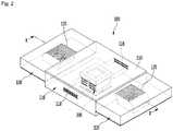
- FIG. 2 is a transparent view showing an interior of a foothold according to a first embodiment of the present disclosure
- FIG. 3 is a plan view of the foothold according to the first embodiment of the present disclosure
- FIG. 4 is a bottom view of the foothold according to the first embodiment of the present disclosure.
- a user H may use a foothold 100 according to an embodiment of the present disclosure when sitting on a chair C and studying at a desk D.
- the foothold 100 may be positioned in a space under the desk D and the user may place their feet on the top surface of the foothold 100. Further, conditioned air may be discharged and supplied to the user's feet F through the top surface of the foothold 100.
- the foothold 100 may be supplied with power through an electrical wire W connected to a power supply.
- the foothold 100 is not limited thereto and may be supplied with power from a battery disposed in the foothold 100.
- the foothold 100 may include a module housing 110 in which a dissipation fan 140 is installed, and blowing portions 120 and 130 in which blowing fans 142 and 144 are installed and that may be disposed at both sides of the module housing 110.
- the blowing portions 120 and 130 may include a first blowing portion 120 disposed at a first side of the module housing 110 and a second blowing portion 130 disposed at a second side of the module housing 110.
- the first and second blowing portions 120 and 130 may be disposed at positions facing each other with the module housing 110 therebetween.
- the blowing fans 142 and 144 may include a first blowing fan 142 provided in the first blowing portion 120 and a second blowing fan 144 provided in the second blowing portion 130.
- the dissipation fan 140 may be installed at a bottom surface portion 113 of the module housing 110. Further, the first blowing fan 142 may be provided at the bottom surface portion 123 of the first blowing portion 120 and the second blowing fan 144 may be provided at the bottom surface portion 133 of the second blowing fan 130.
- thermoelectric module 200 may be installed in the module housing 110 and a dissipation cover 118 through which air, which has passed through the thermoelectric module 200, is discharged may be provided at the front portion and/or the rear portion of the module housing 110.
- a dissipation suction hole may be formed through the bottom surface portion 113 of the module housing 110 and the dissipation fan 140 may be disposed over the dissipation suction hole. As the dissipation fan 140 is driven, air suctioned through the dissipation suction hole may be discharged outside through the dissipation heat sink of the thermoelectric module 200.
- the dissipation fan 140 may be an axial fan and the like.
- the dissipation cover 118 for discharging air that has passed through the dissipation heat sink of the thermoelectric module 200 may be provided at the front surface portion and/or the rear surface portion of the module housing 110.
- the thermoelectric module may generate cold air and dissipate hot air, or generate hot air and dissipate cold air. That is, in the present disclosure, during cooling mode, the thermoelectric element may generate cold air from the top surface and dissipate hot air from the bottom surface. During the heating mode, the thermoelectric element may generate hot air from the top surface and dissipate cold air from the bottom surface. For purposes of the present disclosure, the operation where the thermoelectric element generates cold air from the top surface and dissipates hot air from the bottom surface (i.e., cooling mode) will be described hence forth. It should be noted that the structure of the foothold remains the same whether operating in the cooling mode or heating mode.
- the module housing 110 includes a cover 150.
- the top surface of the cover 150 may provide a surface on which user's feet F are placed. Further, the cover 150 may function as a heat absorption heat sink of the thermoelectric module 200.
- the cover 150 may be detachably coupled to a housing body 111 (see FIG. 5 ). A user may separate the cover 150 from the housing body 111 and then clean the cover 150, and may clean the inside of the housing body 111. Accordingly, it is possible to sanitarily manage the foothold 100.
- a first blowing suction hole may be formed through the bottom surface portion 123 of the first blowing portion 120 and the first blowing fan 142 may be disposed over the first blowing suction hole.
- the first blowing fan 142 When the first blowing fan 142 is driven, air suctioned through the first blowing suction hole flows upward through the first blowing fan 142.
- a first discharge portion 125 through which air is discharged may be formed at the top surface of the first blowing portion 120.
- the first discharge portion 125 may include a plurality of holes.
- the air that has passed through the first blowing fan 142 may be discharged outside through the first discharge portion 125.
- a first blowing channel extending toward the first discharge portion 125 from the first blowing suction hole may be formed in the first blowing portion 120.
- a second blowing suction hole may be formed through the bottom surface portion 133 of the second blowing portion 130 and the second blowing fan 144 may be disposed over the second blowing suction hole.
- the second blowing fan 144 When the second blowing fan 144 is driven, air suctioned through the second blowing suction hole flows upward through the second blowing fan 144.
- a second discharge portion 135 through which air is discharged may be formed at the top surface of the second blowing portion 130.
- the second discharge portion 135 may include a plurality of holes.
- the air that has passed through the second blowing fan 144 may be discharged outside through the second discharge portion 135.
- a second blowing channel extending toward the second discharge portion 135 from the second blowing suction hole may be formed in the second blowing portion 130.
- the first discharge portion 125 and the second discharge portion 135 may be referred to as a "blowing discharge portion" in combination.
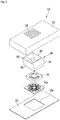
- FIG. 5 is a transparent perspective view showing the configuration of a module housing according to the first embodiment of the present disclosure
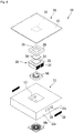
- FIG. 6 is an exploded perspective view of the module housing according to the first embodiment of the present disclosure
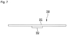
- FIG. 7 is a side view of a cover according to the first embodiment of the present disclosure.
- the module housing 110 may include a housing body 111, a thermoelectric module 200 installed in the housing body 111, and a heat dissipation channel 116 that is disposed in the housing body 111 and through which air, which has passed through the heat dissipation heat sink 210 of the thermoelectric module 200 after being suctioned from the housing body 111, flows.
- a heat dissipation cover 118 may be provided at an end of the heat dissipation channel 116.
- the housing body 111 may have a hexahedral shape with at least a portion of the upper portion open.
- a housing opening 112 may be formed through the housing body 111.
- the heat dissipation fan 140 may be installed at a lower portion in the housing opening 112 and a heat dissipation cover 140a covering the lower portion of the heat dissipation fan 140 may be provided under the heat dissipation fan 140.
- the heat dissipation fan cover 140a may form a portion of the bottom surface of the housing body 111 and may be spaced upward apart from a floor. Further, the heat dissipation fan cover 140a may include a grill structure for preventing entry of foreign substances.
- the housing body 111 may include a front surface portion 111a and a rear surface portion 111b.
- the front surface portion 111a may be a portion to which the heels of the user's feet F are positioned close and the rear surface portion 111b may be a portion to which the toes are positioned close.
- a cover opening 111c to which the heat dissipation cover 118 may be coupled may be formed at each of the front surface portion 111a and the rear surface portion 111b.
- the heat dissipation channel 116 may be disposed to extend from the housing opening 112 toward the front surface portion 111a and from the housing opening 112 toward the rear surface portion 111b.
- thermoelectric module 210 When the heat dissipation fan 140 is driven, air is suctioned from under the housing body 111, flows upward in the housing opening 112, and exchanges heat with the heat dissipation heat sink 210 of the thermoelectric module 210. The air heated through heat exchange diverges to the front surface portion 111a and the rear surface portion 111b of the housing body 111, flows through the heat dissipation channel 116, and is discharged outside through the heat dissipation cover 118.
- the foothold 100 may further include legs 119 disposed at the bottom surface of the housing body 111 to be placed on the floor.
- the legs 119 may extend from both sides of the front surface portion 111a of the housing body 111 toward the rear surface portion 111b. Further, the legs 119 may extend at an angle such that the height of the legs may be higher at the front portion than the rear portion.
- the height of the rear surface portion 111b from the floor may be higher than the height of the front surface portion 111a from the floor.
- the cover 150 is coupled to the top of the housing body 111 and the user's feet F are placed on the cover 150, the toes of the feet F may be positioned higher than the heels. Accordingly, when the user's feet F are placed on the foothold 100, the user may feel comfortable.
- the bottom surface of the housing body 111 may be spaced a predetermined distance apart from the floor by the legs 119.
- the thermoelectric module 200 may be installed in the housing opening 112.
- the foothold 100 does not include parts for operating a refrigeration cycle, for example, parts generating large noise such as a compressor, so an effect of reducing noise while the foothold 100 is operated may be obtained.
- thermoelectric module 200 may be disposed at the center portion of the housing body 111 in the front-rear direction. Further, the heat dissipation channel 116 may be disposed to extend forward and rearward from the thermoelectric module 200.
- thermoelectric module 200 may include a heat dissipation heat sink 210 being in contact with a thermoelectric element 220.
- the heat dissipation heat sink 210 may include a heat sink main body 211 having a substantially square or rectangular plate shape, and an element coupling portion 212 that may protrude from the top surface of the heat sink main body 211 and to which the thermoelectric element 220 may be attached or fastened.
- the thermoelectric element 220 may be an element that implements cooling and heat generation using Peltier effect.
- a heat absorption side of the thermoelectric element may be disposed to face the upper portion of the housing body 111 and a heat dissipation side of the thermoelectric element may be disposed to face the lower portion of the housing body 111 during cooling.
- the heat dissipation side of the thermoelectric element may be disposed to face the upper portion of the body 111 and the heat absorption side of the thermoelectric element may be disposed to face the lower portion of the body 111.
- the heat dissipation heat sink 210 may include a heat sink fin 215 that is disposed under the heat sink main body 211 and exchanges heat with air suctioned through the lower portion of the housing body 111.
- the heat sink fin 215 may be a plurality of pieces, such as fins, and the plurality of fins may be coupled to the bottom surface of the heat sink main body 211 and may extend downward.
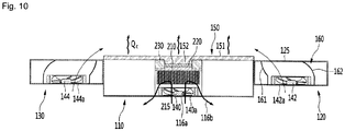
- the heat dissipation channel 116 may include a sink suction side channel 116a (see FIG. 10 ) forming an air channel from the heat dissipation fan 140 to the heat dissipation heat sink 210, and a sink discharge side channel 116b (see FIG. 10 ) forming an air channel from the heat dissipation heat sink 210 to the heat dissipation cover 118.
- the sink suction side channel 116a and the sink discharge side channel 116b may be channels disposed in the module housing 110.
- the sink suction side channel 116a may be disposed towards the heat dissipation heat sink 210 from the bottom surface of the housing body 111 and may be disposed at the center portion of the housing body 111 in the front-rear direction.
- the sink suction side channel 116a may form at least a portion of the housing opening 112.
- the sink discharge side channel 116b may be disposed towards the front surface portion 111a and the rear surface portion 111b from the housing body 111 to the heat dissipation heat sink 210.
- the thermoelectric module 200 may further include a heat absorption heat sink disposed over the module body 210.
- the cover 150 may be a heat absorption heat sink.
- the heat absorption heat sink 150 (cover) may be disposed in contact with the heat absorption portion at the upper portion of the thermoelectric element 220 and the heat dissipation heat sink 210 may be disposed in contact with a heat dissipation portion at the lower portion of the thermoelectric element 220.
- the heat absorption portion and the heat dissipation portion of the thermoelectric element may have a shape that may come in surface contact, and may form opposite surfaces.
- the thermoelectric element module 200 may further include a module insulator 230 disposed between the heat absorption heat sink 150 and the heat dissipation heat sink 210.
- the module insulator 230 may be disposed to surround the edge of the thermoelectric element 220.
- An insulator opening 235 may be formed through the module insulator 230.
- the insulator opening 235 may be formed in a hole shape through the top and bottom surfaces of the module insulator 230.
- a plate protrusion 152 of the cover 150 may be inserted in the insulator opening 235 in contact with the thermoelectric element 220.
- the thermoelectric element 220 may be positioned in the insulator opening 235.
- the plate protrusion 152 may be configured to protrude from the bottom surface of the cover 150.
- the cover 150 may include a cover plate 151 having a substantially square or rectangular plate shape and the plate protrusion 152 provided at the bottom surface of the cover plate 151.
- the top surface of the cover plate 151 may form a surface on which user's feet F are placed.
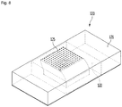
- FIG. 8 is a transparent perspective view showing the configuration of a first blowing portion according to the first embodiment of the present disclosure
- FIG. 9 is an exploded perspective view of the first blowing portion according to the first embodiment of the present disclosure
- FIG. 10 is a cross-sectional view taken along line X-X' of FIG. 2 .
- the foothold 100 may include a first blowing portion 120 and a second blowing portion 130 provided at both sides of the module housing 110.
- the first and second blowing portions 120 and 130 may have symmetric configurations with the module housing 110 therebetween. Further, the configurations of the first and second blowing portions 120 and 130 may be the same or similar, so the first blowing portion 120 is mainly described herein and the description of the first blowing portion 120 is equally applicable to the second blowing portion 130.
- the first blowing portion 120 may include a blowing portion body 121 and a bottom surface portion 123 coupled to the lower portion of the blowing portion body 121 and having a bottom surface opening 123a.
- the blowing portion body 121 has a square or rectangular parallelepiped shape with an open lower portion and a first discharge portion 125 through which air is discharged disposed at the top surface of the blowing portion body 121. Further, a body recession 122 in which the blowing fan 142 and the channel guide 160 may be disposed may be disposed in the blowing portion body 121. The body recession 122 may be configured to be recessed upward from the bottom surface of the blowing portion body 121.
- the bottom surface portion 123 has a substantially square or rectangular plate shape and the bottom surface opening 123a may be disposed at the center portion of the bottom surface portion 123.
- the bottom surface opening 123a may function as a suction hole for suctioning air.
- a first blowing fan cover 142a may be coupled to the bottom surface opening 123a and the first blowing fan 142 may be positioned over the first blowing fan cover 142a.
- the first blowing fan 142 may be an axial fan and the like.
- the first blowing portion 120 may further include a channel guide 160 installed in the blowing portion body 121.
- the first blowing fan 142 may be disposed in the channel guide 160 and the air that has passed through the first blowing fan 142 flows toward the first discharge portion 125 through the internal channel of the channel guide 160.
- the channel guide 160 may include a guide body 161 having a fan installation space 163 and a guide discharge portion 165 disposed and opened at the upper end of the guide body 161.
- the guide body 161 may include a housing that is vertically hollow and the first blowing fan 142 may be positioned at the lower portion in the guide body 161.
- the guide body 161 may include an inclined portion 162 for guiding air to the module housing 110.
- the inclined portion 162 may extend from the lower end of the guide body 161 to the guide discharge portion 165 and to have a predetermined curvature or slope.
- the first blowing portion 120 may be disposed at the right side of the module housing 110, and as shown in FIG. 9 , the inclined portion 162 may extend from the lower end of the guide body 161 toward the center portion of the module housing 110 to be rounded or inclined towards the left going upward (see FIG. 10 ).
- the second blowing portion 130 may be disposed at the left side of the module housing 110 and the inclined portion 162 of the second blowing portion 130 may extend from the lower end of the guide body 161 toward the center portion of the module housing 110 to be rounded or inclined towards the right going upward (see FIG. 10 ).
- the plate protrusion 152 may be inserted in the insulator opening 235 of the module insulator 230. Further, the plate protrusion 152 may be in contact with the thermoelectric element 220 positioned in the insulator opening 235.
- the air suctioned into the module housing 110 exchanges heat with the heat dissipation heat sink 210 and may be discharged out of the module housing 110 through the heat dissipation channels 116a and 116b.
- the plate protrusion 152 may be cooled by the heat absorption portion of the thermoelectric element 220, and the cover plate 151 may be cooled by conduction through the plate protrusion 152. That is, the cover 150 may be one component of the heat absorption heat sink of the thermoelectric module 200. As a result, the top surface of the cover plate 151 being brought in direct contact with the feet of a user, is able to supply heat Qc to the user.
- the air suctioned into the first and second blowing portions 120 and 130 may be discharged to the center portion of the module housing 110 through the first and second blowing fans 142 and 144 and may be supplied to user's feet F.
- the user with their feet F on the top surface of the cover 150 may feel cool by contact of the feet with the cover 150 cooled by the thermoelectric module 200 and the air discharged through the first and second discharge portions 125 and 135 of the respective first and second blowing portions 120 and 130.
- FIG. 11 is a plan view of the foothold according to a second embodiment of the present disclosure
- FIG. 12 is a cross-sectional view of the foothold according to the second embodiment of the present disclosure.
- a foothold 100a may include a module housing 1110 and a blowing portion 120' provided at a side of the module housing 110.
- the description about the module housing 110 described in the first embodiment is equally applicable to the module housing 110 of the second embodiment.
- the blowing portion 120' may include a blowing fan 142' and a blowing fan cover 142a' disposed under the blowing fan 142'. Further, the blowing portion 120' may further include a channel guide 160 that guides the flow direction of the air that has passed through the blowing fan 142' to discharge the air to the space at the module housing 110. For the description about the blowing fan 142', the blowing fan cover 142'a, and the channel guide 160, the description about these components in the first embodiment is equally applicable.
- the blowing portion 120' may include a blowing portion body 121' having a top surface on which a first discharge portion 125' is disposed. Further, the foothold 100a may further include an air guide 180 disposed at the upper portion of the blowing portion 120'.
- the air guide 180 may be provided to protrude from the top surface of the blowing portion body 121' and may be disposed between the first discharge portion 125' and the cover 150. Further, the air guide 180 may be formed to be rounded or inclined to have a cross-section like a wing of an airplane.
- the air guide 180 may include a first surface 181 extending from the top surface of the blowing portion body 121' to incline upward at a first angle ⁇ 1 and a second surface 182 extending from the upper end of the first surface 181 to decline downward at a second angle ⁇ 2 towards the cover 150.
- the second angle ⁇ 2 may be greater than the first angle ⁇ 1.
- the air discharged from the first discharge portion 125' of the blowing portion 120' flows to the cover 150 along the first and second surface 181 and 182 of the air guide 180, and in this process, reduction of flow speed may be produced while passing on the surface of the air guide (coanda effect). Accordingly, the air supply ability of the blowing portion 120' may be improved.
- FIG. 13 is a transparent perspective view of a foothold according to a third embodiment of the present disclosure.
- a foothold 100b according to the third embodiment of the present disclosure includes a module housing 110.
- the description about the module housing 110 described in the first embodiment is equally applicable to the module housing 110 of the third embodiment.
- the foothold 100b may further include a blowing fan 190 disposed at a side of the module housing 110.
- the blowing fan 190 may be an axial fan and the like. Further, a fan supporting portion 195 that supports the blowing fan 190 may be provided under the blowing fan 190.
- the height of the fan supporting portion 195 may the same as or greater than the height of the module housing 110. Accordingly, the height of the center portion of the blowing fan 190 may be greater than the height of the module housing 110, particularly, the cover 150. When the blowing fan 190 is driven, the air generated from the blowing fan 190 may be supplied to the space over the cover 150.
- thermoelectric module 200 air may be supplied over the cover 150 cooled by the thermoelectric module 200, and the user may feel cooler on their feet F.
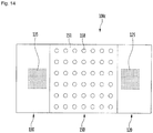
- FIG. 14 is a plan view of the foothold according to a fourth embodiment of the present disclosure.
- a foothold 100c may include a cover 150 having fins 158.
- the cover 150 may include a cover plate 151 having a square or rectangular plate shape and fins 158 provided at the top surface of the cover plate 151. Further, the plate protrusion 152 described in the first embodiment may be provided on the bottom surface of the cover plate 151.
- the fins 158 may be configured to have a semispherical shape.
- the heat exchange area of the cover 150 may be increased by the fins 158, and the heat transfer efficiency may be improved. Further, since user's feet F are placed on the top surface of the cover 150, it may be possible to additionally obtain an acupressure effect.
Landscapes
- Engineering & Computer Science (AREA)
- Mechanical Engineering (AREA)
- General Engineering & Computer Science (AREA)
- Chemical & Material Sciences (AREA)
- Combustion & Propulsion (AREA)
- Physics & Mathematics (AREA)
- Thermal Sciences (AREA)
- Life Sciences & Earth Sciences (AREA)
- Sustainable Development (AREA)
- Health & Medical Sciences (AREA)
- Biomedical Technology (AREA)
- Heart & Thoracic Surgery (AREA)
- Vascular Medicine (AREA)
- Animal Behavior & Ethology (AREA)
- General Health & Medical Sciences (AREA)
- Public Health (AREA)
- Veterinary Medicine (AREA)
- Devices For Blowing Cold Air, Devices For Blowing Warm Air, And Means For Preventing Water Condensation In Air Conditioning Units (AREA)
- Structures Of Non-Positive Displacement Pumps (AREA)
- Thermotherapy And Cooling Therapy Devices (AREA)
Abstract
Description
- The present disclosure is related to a foothold including a thermoelectric module.
- When sitting and studying at a desk, sometimes a person feels hot or cold at their lower body. This is because the sides and the front of the desk are closed to the outside, so ventilation is poor. In particular, during the summer season with the hot weather, even if an air conditioner is operated, cold air does not reach well into the space under the desk, so the person feels hot at their lower body, and sweats if severe. In this situation, if the person is studying, there is a problem that the person's concentration decreases, and their learning performance deteriorates.
- In order to solve this problem, there is inconvenience in that the person has to put and operate a discrete cooling device such as a mobile air conditioner or an electric fan at the side of the desk.
- In order to solve the problems described above, an aspect of the present disclosure is to provide a foothold including a thermoelectric module, the foothold being able to make a user feel comfortable by supplying conditioned air to their lower body, particularly, the feet.
- Another aspect is to provide a foothold including a thermoelectric module, the foothold being able to generate cold/hot air, using a thermoelectric module, and to additionally supply air to the user's feet.
- Another aspect is to provide a foothold including a thermoelectric module, the foothold being able to supply cold/hot air to the user's both feet by configuring at least two air supply channels.
- Another aspect is to provide a foothold including a thermoelectric module in which air that has passed through a dissipation heat sink can smoothly flow by configuring a dissipation channel between two air supply channels.
- Another aspect is to provide a foothold including a thermoelectric module in which a blowing portion is provided at both sides of a module housing, in which a thermoelectric module is installed, and air is supplied from the blowing portions, thereby being able to supply coldness and/or hotness to the user's feet through conduction and convection.
- Another aspect is to provide a foothold including a thermoelectric module in which a fan for supplying air and a dissipation fan are separately provided, so an air supply channel and a dissipation channel can be easily formed.
- Another aspect is to provide a foothold including a thermoelectric module in which fins are provided on the top surface of a cover, thereby being able to increase a cold/heat transfer rate from the cover.
- Another aspect is to provide a foothold including a thermoelectric module in which a cover of a module housing is provided to be detachable, so the cover can be washed.
- Another aspect is to provide a foothold including a thermoelectric module in which an air guide is provided between a module housing and a blowing portion, whereby air supplied from the blowing portion can be easily supplied to the module housing.
- Another aspect is to provide a foothold including a thermoelectric module in which a blowing fan is provided at a side of a module housing and the blowing fan is disposed higher than the module housing by a fan supporting portion, whereby air can be easily supplied to the space over the module housing from the blowing fan.
- A foothold including a thermoelectric module according to an embodiment of the present disclosure includes a module housing in which a dissipation fan and a thermoelectric element are provided, and a blowing portion disposed at a first side of the module housing and having a blowing fan.
- The thermoelectric module includes a dissipation heat sink installed over the dissipation fan.
- The thermoelectric module further includes a cover provided at the upper portion of the module housing and having a top surface on user's feet are place, and the cover functions as a heat absorption/dissipation heat sink.
- The thermoelectric module further includes a thermoelectric element disposed between the dissipation heat sink and the cover.
- The dissipation fan or the blowing fan is configured as an axial fan.
- The module housing my include: a housing body having a housing opening formed through the housing body in an up-down direction; and a cover disposed on the housing body.
- The dissipation fan is disposed at a lower portion in the housing opening, and the dissipation heat sink is disposed over the dissipation fan.
- The foothold further includes: a cover opening formed on at least one surface of the housing main body and discharging air that has passed through the dissipation heat sink; and a dissipation cover disposed in the cover opening.
- A dissipation channel is formed in the module housing.
- The dissipation channel includes: a sink suction side channel forming an air channel from the dissipation fan to the dissipation heat sink; and a sink discharge side channel extending from the dissipation heat sink to the dissipation cover.
- The cover includes: a cover plate disposed on the housing body; and a plate protrusion protruding downward from a bottom surface of the cover plate, the plate protrusion being in contact with a heat absorption/dissipation portion of the thermoelectric element.
- The foothold includes a module insulator surrounding the thermoelectric element and having an insulator opening, in which the plate protrusion is inserted into the insulator opening.
- The blowing portion further includes a channel guide forming an installation space in which the blowing fan is installed, and having a guide discharge portion at an upper end thereof.
- The channel guide includes an inclined portion configured to be rounded or inclined toward the module housing.
- The blowing portion includes: a first blowing portion disposed at a first side of the module housing; and a second blowing portion disposed at a second side of the module housing.
- The blowing portion further includes: a blowing discharge portion formed on a top surface of the blowing portion to discharge air; and an air guide guiding air, which has passed through the blowing fan, over the cover.
- The air guide is disposed between the blowing discharge portion and the cover.
- The air guide includes: a first surface extending from the top surface of the blowing portion to be inclined upward at a first angle; and a second surface extending from an upper end of the first surface to be inclined downward at a second angle toward the cover.
- The second angle is greater than the first angle.
- The blowing portion further includes a fan support portion configured to support the blowing fan, and a height of a center portion of the blowing fan is greater than a height of the cover.
- The cover includes: a cover plate disposed on the housing body; and at least one fine protruding upward from a top surface of the cover plate.
- According to the foothold according to the present disclosure, there is an effect that it is possible to make a user feel comfortable by supplying conditioned air to the lower portion of the user's body, particularly, to the feet.
- Further, it is possible to generate cold/hot air, using a thermoelectric module, and additionally to supply the air to user's feet.
- Further, by configuring at least two air supply channels, it is possible to effectively supply air to user's both feet.
- Further, by configuring a dissipation channel between the two air supply channels, air that has passed through the dissipation heat sink can smoothly flow.
- Further, a blowing portion is provided at both sides of a module housing, in which a thermoelectric module is installed, and air is supplied from the blowing portions, thereby being able to supply coldness and/or hotness to user's feet through conduction and convection.
- Further, fins are provided on the top surface of a cover, whereby a heat/cold transfer rate from the cover can be increased.
- Further, a cover of the module housing is provided to be detachable, so the cover can be washed.
- Further, an air guide is provided between a module housing and a blowing portion, whereby air supplied from the blowing portion can be easily supplied to the module housing.
- Further, a blowing fan is provided at a side of a module housing and the blowing fan is disposed higher than the module housing by a fan supporting portion, whereby air can be easily supplied to the space over the module housing from the blowing fan.
-
-
FIG. 1 is a view showing a user using a foothold according to an embodiment of the present disclosure. -
FIG. 2 is a transparent view showing an interior of a foothold according to a first embodiment of the present disclosure. -
FIG. 3 is a plan view of the foothold according to the first embodiment of the present disclosure. -
FIG. 4 is a bottom view of the foothold according to the first embodiment of the present disclosure. -
FIG. 5 is a transparent perspective view showing the configuration of a module housing according to the first embodiment of the present disclosure. -
FIG. 6 is an exploded perspective view of the module housing according to the first embodiment of the present disclosure. -
FIG. 7 is a side view of a cover according to the first embodiment of the present disclosure. -
FIG. 8 is a transparent perspective view showing the configuration of a first blowing portion according to the first embodiment of the present disclosure. -
FIG. 9 is an exploded perspective view of the first blowing portion according to the first embodiment of the present disclosure. -
FIG. 10 is a cross-sectional view taken along line X-X' ofFIG. 2 . -
FIG. 11 is a plan view of a foothold according to a second embodiment of the present disclosure. -
FIG. 12 is a cross-sectional view of the foothold according to the second embodiment of the present disclosure. -
FIG. 13 is a transparent perspective view of a foothold according to a third embodiment of the present disclosure. -
FIG. 14 is a plan view of the foothold according to a fourth embodiment of the present disclosure. - Hereinafter, embodiments of the present disclosure are described in detail with reference to exemplary drawings. It should be noted that when components are given reference numerals in the drawings, the same or similar components may be given the same reference numerals even if they are shown in different drawings. Further, in the following description of embodiments of the present disclosure, when detailed description of well-known configurations or functions is determined as obscuring the understanding of the embodiments of the present disclosure, they may be omitted or not described in detail.
- Further, terms 'first', 'second', 'A', 'B', '(a)', and '(b)' may be used in the following description of the components of embodiments of the present disclosure. The terms are provided only for discriminating components from other components and, the essence, sequence, or order of the components are not limited by the terms. When a component is described as being "connected", "combined", or "coupled" with another component, it should be understood that the component may be connected or coupled to another component directly or with another component interposing therebetween.
-
FIG. 1 is a view showing a user using a foothold according to an embodiment of the present disclosure,FIG. 2 is a transparent view showing an interior of a foothold according to a first embodiment of the present disclosure,FIG. 3 is a plan view of the foothold according to the first embodiment of the present disclosure, andFIG. 4 is a bottom view of the foothold according to the first embodiment of the present disclosure. - Referring to
FIG. 1 , a user H may use afoothold 100 according to an embodiment of the present disclosure when sitting on a chair C and studying at a desk D. - In detail, the
foothold 100 may be positioned in a space under the desk D and the user may place their feet on the top surface of thefoothold 100. Further, conditioned air may be discharged and supplied to the user's feet F through the top surface of thefoothold 100. - The
foothold 100 may be supplied with power through an electrical wire W connected to a power supply. However, thefoothold 100 is not limited thereto and may be supplied with power from a battery disposed in thefoothold 100. - Referring to
FIGS. 2 to 4 , thefoothold 100 according to an embodiment of the present disclosure may include amodule housing 110 in which adissipation fan 140 is installed, and blowingportions fans module housing 110. - The blowing
portions first blowing portion 120 disposed at a first side of themodule housing 110 and asecond blowing portion 130 disposed at a second side of themodule housing 110. The first andsecond blowing portions module housing 110 therebetween. The blowingfans first blowing fan 142 provided in thefirst blowing portion 120 and asecond blowing fan 144 provided in thesecond blowing portion 130. - The
dissipation fan 140 may be installed at abottom surface portion 113 of themodule housing 110. Further, the first blowingfan 142 may be provided at thebottom surface portion 123 of thefirst blowing portion 120 and thesecond blowing fan 144 may be provided at thebottom surface portion 133 of thesecond blowing fan 130. - A
thermoelectric module 200 may be installed in themodule housing 110 and adissipation cover 118 through which air, which has passed through thethermoelectric module 200, is discharged may be provided at the front portion and/or the rear portion of themodule housing 110. - A dissipation suction hole may be formed through the
bottom surface portion 113 of themodule housing 110 and thedissipation fan 140 may be disposed over the dissipation suction hole. As thedissipation fan 140 is driven, air suctioned through the dissipation suction hole may be discharged outside through the dissipation heat sink of thethermoelectric module 200. For example, thedissipation fan 140 may be an axial fan and the like. - The
dissipation cover 118 for discharging air that has passed through the dissipation heat sink of thethermoelectric module 200 may be provided at the front surface portion and/or the rear surface portion of themodule housing 110. - Based on a polarity of the thermoelectric element 220 (see
FIG. 6 ) of thethermoelectric module 200, the thermoelectric module may generate cold air and dissipate hot air, or generate hot air and dissipate cold air. That is, in the present disclosure, during cooling mode, the thermoelectric element may generate cold air from the top surface and dissipate hot air from the bottom surface. During the heating mode, the thermoelectric element may generate hot air from the top surface and dissipate cold air from the bottom surface. For purposes of the present disclosure, the operation where the thermoelectric element generates cold air from the top surface and dissipates hot air from the bottom surface (i.e., cooling mode) will be described hence forth. It should be noted that the structure of the foothold remains the same whether operating in the cooling mode or heating mode. - The
module housing 110 includes acover 150. The top surface of thecover 150 may provide a surface on which user's feet F are placed. Further, thecover 150 may function as a heat absorption heat sink of thethermoelectric module 200. - The
cover 150 may be detachably coupled to a housing body 111 (seeFIG. 5 ). A user may separate thecover 150 from thehousing body 111 and then clean thecover 150, and may clean the inside of thehousing body 111. Accordingly, it is possible to sanitarily manage thefoothold 100. - A first blowing suction hole may be formed through the
bottom surface portion 123 of thefirst blowing portion 120 and the first blowingfan 142 may be disposed over the first blowing suction hole. When the first blowingfan 142 is driven, air suctioned through the first blowing suction hole flows upward through the first blowingfan 142. - A
first discharge portion 125 through which air is discharged may be formed at the top surface of thefirst blowing portion 120. Thefirst discharge portion 125 may include a plurality of holes. The air that has passed through the first blowingfan 142 may be discharged outside through thefirst discharge portion 125. A first blowing channel extending toward thefirst discharge portion 125 from the first blowing suction hole may be formed in thefirst blowing portion 120. - A second blowing suction hole may be formed through the
bottom surface portion 133 of thesecond blowing portion 130 and thesecond blowing fan 144 may be disposed over the second blowing suction hole. When thesecond blowing fan 144 is driven, air suctioned through the second blowing suction hole flows upward through thesecond blowing fan 144. - A
second discharge portion 135 through which air is discharged may be formed at the top surface of thesecond blowing portion 130. Thesecond discharge portion 135 may include a plurality of holes. The air that has passed through thesecond blowing fan 144 may be discharged outside through thesecond discharge portion 135. A second blowing channel extending toward thesecond discharge portion 135 from the second blowing suction hole may be formed in thesecond blowing portion 130. Thefirst discharge portion 125 and thesecond discharge portion 135 may be referred to as a "blowing discharge portion" in combination. -
FIG. 5 is a transparent perspective view showing the configuration of a module housing according to the first embodiment of the present disclosure,FIG. 6 is an exploded perspective view of the module housing according to the first embodiment of the present disclosure, andFIG. 7 is a side view of a cover according to the first embodiment of the present disclosure. - Referring to
FIGS. 5 to 7 , themodule housing 110 according to the first embodiment of the present disclosure may include ahousing body 111, athermoelectric module 200 installed in thehousing body 111, and aheat dissipation channel 116 that is disposed in thehousing body 111 and through which air, which has passed through the heatdissipation heat sink 210 of thethermoelectric module 200 after being suctioned from thehousing body 111, flows. - Further, a
heat dissipation cover 118 may be provided at an end of theheat dissipation channel 116. - In detail, the
housing body 111 may have a hexahedral shape with at least a portion of the upper portion open. Ahousing opening 112 may be formed through thehousing body 111. Theheat dissipation fan 140 may be installed at a lower portion in thehousing opening 112 and aheat dissipation cover 140a covering the lower portion of theheat dissipation fan 140 may be provided under theheat dissipation fan 140. The heatdissipation fan cover 140a may form a portion of the bottom surface of thehousing body 111 and may be spaced upward apart from a floor. Further, the heatdissipation fan cover 140a may include a grill structure for preventing entry of foreign substances. - The
housing body 111 may include afront surface portion 111a and arear surface portion 111b. For example, thefront surface portion 111a may be a portion to which the heels of the user's feet F are positioned close and therear surface portion 111b may be a portion to which the toes are positioned close. - A
cover opening 111c to which theheat dissipation cover 118 may be coupled may be formed at each of thefront surface portion 111a and therear surface portion 111b. Theheat dissipation channel 116 may be disposed to extend from thehousing opening 112 toward thefront surface portion 111a and from thehousing opening 112 toward therear surface portion 111b. - When the
heat dissipation fan 140 is driven, air is suctioned from under thehousing body 111, flows upward in thehousing opening 112, and exchanges heat with the heatdissipation heat sink 210 of thethermoelectric module 210. The air heated through heat exchange diverges to thefront surface portion 111a and therear surface portion 111b of thehousing body 111, flows through theheat dissipation channel 116, and is discharged outside through theheat dissipation cover 118. - The
foothold 100 may further includelegs 119 disposed at the bottom surface of thehousing body 111 to be placed on the floor. Thelegs 119 may extend from both sides of thefront surface portion 111a of thehousing body 111 toward therear surface portion 111b. Further, thelegs 119 may extend at an angle such that the height of the legs may be higher at the front portion than the rear portion. - By the configuration of the
legs 119, the height of therear surface portion 111b from the floor may be higher than the height of thefront surface portion 111a from the floor. When thecover 150 is coupled to the top of thehousing body 111 and the user's feet F are placed on thecover 150, the toes of the feet F may be positioned higher than the heels. Accordingly, when the user's feet F are placed on thefoothold 100, the user may feel comfortable. Further, the bottom surface of thehousing body 111 may be spaced a predetermined distance apart from the floor by thelegs 119. - The
thermoelectric module 200 may be installed in thehousing opening 112. Thefoothold 100 does not include parts for operating a refrigeration cycle, for example, parts generating large noise such as a compressor, so an effect of reducing noise while thefoothold 100 is operated may be obtained. - The
thermoelectric module 200 may be disposed at the center portion of thehousing body 111 in the front-rear direction. Further, theheat dissipation channel 116 may be disposed to extend forward and rearward from thethermoelectric module 200. - In detail, the
thermoelectric module 200 may include a heatdissipation heat sink 210 being in contact with athermoelectric element 220. The heatdissipation heat sink 210 may include a heat sinkmain body 211 having a substantially square or rectangular plate shape, and anelement coupling portion 212 that may protrude from the top surface of the heat sinkmain body 211 and to which thethermoelectric element 220 may be attached or fastened. - The
thermoelectric element 220 may be an element that implements cooling and heat generation using Peltier effect. A heat absorption side of the thermoelectric element may be disposed to face the upper portion of thehousing body 111 and a heat dissipation side of the thermoelectric element may be disposed to face the lower portion of thehousing body 111 during cooling. During heating, the heat dissipation side of the thermoelectric element may be disposed to face the upper portion of thebody 111 and the heat absorption side of the thermoelectric element may be disposed to face the lower portion of thebody 111. - The heat
dissipation heat sink 210 may include aheat sink fin 215 that is disposed under the heat sinkmain body 211 and exchanges heat with air suctioned through the lower portion of thehousing body 111. Theheat sink fin 215 may be a plurality of pieces, such as fins, and the plurality of fins may be coupled to the bottom surface of the heat sinkmain body 211 and may extend downward. - The
heat dissipation channel 116 may include a sinksuction side channel 116a (seeFIG. 10 ) forming an air channel from theheat dissipation fan 140 to the heatdissipation heat sink 210, and a sinkdischarge side channel 116b (seeFIG. 10 ) forming an air channel from the heatdissipation heat sink 210 to theheat dissipation cover 118. - The sink
suction side channel 116a and the sinkdischarge side channel 116b may be channels disposed in themodule housing 110. - In detail, the sink
suction side channel 116a may be disposed towards the heatdissipation heat sink 210 from the bottom surface of thehousing body 111 and may be disposed at the center portion of thehousing body 111 in the front-rear direction. The sinksuction side channel 116a may form at least a portion of thehousing opening 112. - The sink
discharge side channel 116b may be disposed towards thefront surface portion 111a and therear surface portion 111b from thehousing body 111 to the heatdissipation heat sink 210. - The
thermoelectric module 200 may further include a heat absorption heat sink disposed over themodule body 210. Thecover 150 may be a heat absorption heat sink. - The heat absorption heat sink 150 (cover) may be disposed in contact with the heat absorption portion at the upper portion of the
thermoelectric element 220 and the heatdissipation heat sink 210 may be disposed in contact with a heat dissipation portion at the lower portion of thethermoelectric element 220. The heat absorption portion and the heat dissipation portion of the thermoelectric element may have a shape that may come in surface contact, and may form opposite surfaces. - The
thermoelectric element module 200 may further include amodule insulator 230 disposed between the heatabsorption heat sink 150 and the heatdissipation heat sink 210. For example, themodule insulator 230 may be disposed to surround the edge of thethermoelectric element 220. - An
insulator opening 235 may be formed through themodule insulator 230. Theinsulator opening 235 may be formed in a hole shape through the top and bottom surfaces of themodule insulator 230. - A
plate protrusion 152 of thecover 150 may be inserted in theinsulator opening 235 in contact with thethermoelectric element 220. Thethermoelectric element 220 may be positioned in theinsulator opening 235. - The
plate protrusion 152 may be configured to protrude from the bottom surface of thecover 150. In detail, thecover 150 may include acover plate 151 having a substantially square or rectangular plate shape and theplate protrusion 152 provided at the bottom surface of thecover plate 151. The top surface of thecover plate 151 may form a surface on which user's feet F are placed. -
FIG. 8 is a transparent perspective view showing the configuration of a first blowing portion according to the first embodiment of the present disclosure,FIG. 9 is an exploded perspective view of the first blowing portion according to the first embodiment of the present disclosure, andFIG. 10 is a cross-sectional view taken along line X-X' ofFIG. 2 . - Referring to
FIGS. 8 and9 , thefoothold 100 according to the first embodiment of the present disclosure may include afirst blowing portion 120 and asecond blowing portion 130 provided at both sides of themodule housing 110. The first andsecond blowing portions module housing 110 therebetween. Further, the configurations of the first andsecond blowing portions first blowing portion 120 is mainly described herein and the description of thefirst blowing portion 120 is equally applicable to thesecond blowing portion 130. - The
first blowing portion 120 may include a blowingportion body 121 and abottom surface portion 123 coupled to the lower portion of the blowingportion body 121 and having abottom surface opening 123a. - The blowing
portion body 121 has a square or rectangular parallelepiped shape with an open lower portion and afirst discharge portion 125 through which air is discharged disposed at the top surface of the blowingportion body 121. Further, abody recession 122 in which the blowingfan 142 and thechannel guide 160 may be disposed may be disposed in the blowingportion body 121. Thebody recession 122 may be configured to be recessed upward from the bottom surface of the blowingportion body 121. - The
bottom surface portion 123 has a substantially square or rectangular plate shape and thebottom surface opening 123a may be disposed at the center portion of thebottom surface portion 123. Thebottom surface opening 123a may function as a suction hole for suctioning air. A first blowingfan cover 142a may be coupled to thebottom surface opening 123a and the first blowingfan 142 may be positioned over the first blowingfan cover 142a. Thefirst blowing fan 142 may be an axial fan and the like. - The
first blowing portion 120 may further include achannel guide 160 installed in the blowingportion body 121. Thefirst blowing fan 142 may be disposed in thechannel guide 160 and the air that has passed through the first blowingfan 142 flows toward thefirst discharge portion 125 through the internal channel of thechannel guide 160. - In detail, the
channel guide 160 may include aguide body 161 having afan installation space 163 and aguide discharge portion 165 disposed and opened at the upper end of theguide body 161. Theguide body 161 may include a housing that is vertically hollow and the first blowingfan 142 may be positioned at the lower portion in theguide body 161. - The
guide body 161 may include aninclined portion 162 for guiding air to themodule housing 110. Theinclined portion 162 may extend from the lower end of theguide body 161 to theguide discharge portion 165 and to have a predetermined curvature or slope. - For example, the
first blowing portion 120 may be disposed at the right side of themodule housing 110, and as shown inFIG. 9 , theinclined portion 162 may extend from the lower end of theguide body 161 toward the center portion of themodule housing 110 to be rounded or inclined towards the left going upward (seeFIG. 10 ). - On the contrary, the
second blowing portion 130 may be disposed at the left side of themodule housing 110 and theinclined portion 162 of thesecond blowing portion 130 may extend from the lower end of theguide body 161 toward the center portion of themodule housing 110 to be rounded or inclined towards the right going upward (seeFIG. 10 ). - When the first blowing
fan 142 is driven, air suctioned through thebottom surface opening 123a flows upward through the first blowingfan 142, turns in thechannel guide 160, and may be discharged to the space over themodule housing 110 through thefirst discharge portion 125. - Referring to
FIG. 10 , with thecover 150 according to the first embodiment of the present disclosure coupled to the top of thehousing body 111, theplate protrusion 152 may be inserted in theinsulator opening 235 of themodule insulator 230. Further, theplate protrusion 152 may be in contact with thethermoelectric element 220 positioned in theinsulator opening 235. - When the
heat dissipation fan 140 is driven, the air suctioned into themodule housing 110 exchanges heat with the heatdissipation heat sink 210 and may be discharged out of themodule housing 110 through theheat dissipation channels - Meanwhile, the
plate protrusion 152 may be cooled by the heat absorption portion of thethermoelectric element 220, and thecover plate 151 may be cooled by conduction through theplate protrusion 152. That is, thecover 150 may be one component of the heat absorption heat sink of thethermoelectric module 200. As a result, the top surface of thecover plate 151 being brought in direct contact with the feet of a user, is able to supply heat Qc to the user. - When the first and second blowing
fans second blowing portions module housing 110 through the first and second blowingfans cover 150 may feel cool by contact of the feet with thecover 150 cooled by thethermoelectric module 200 and the air discharged through the first andsecond discharge portions second blowing portions -
FIG. 11 is a plan view of the foothold according to a second embodiment of the present disclosure andFIG. 12 is a cross-sectional view of the foothold according to the second embodiment of the present disclosure. - Referring to
FIGS. 11 and12 , afoothold 100a according to the second embodiment of the present disclosure may include a module housing 1110 and a blowing portion 120' provided at a side of themodule housing 110. The description about themodule housing 110 described in the first embodiment is equally applicable to themodule housing 110 of the second embodiment. - The blowing portion 120' may include a blowing fan 142' and a blowing
fan cover 142a' disposed under the blowing fan 142'. Further, the blowing portion 120' may further include achannel guide 160 that guides the flow direction of the air that has passed through the blowing fan 142' to discharge the air to the space at themodule housing 110. For the description about the blowing fan 142', the blowing fan cover 142'a, and thechannel guide 160, the description about these components in the first embodiment is equally applicable. - The blowing portion 120' may include a blowing portion body 121' having a top surface on which a first discharge portion 125' is disposed. Further, the
foothold 100a may further include anair guide 180 disposed at the upper portion of the blowing portion 120'. - The
air guide 180 may be provided to protrude from the top surface of the blowing portion body 121' and may be disposed between the first discharge portion 125' and thecover 150. Further, theair guide 180 may be formed to be rounded or inclined to have a cross-section like a wing of an airplane. - In detail, the
air guide 180 may include afirst surface 181 extending from the top surface of the blowing portion body 121' to incline upward at a first angle θ1 and asecond surface 182 extending from the upper end of thefirst surface 181 to decline downward at a second angle θ2 towards thecover 150. The second angle θ2 may be greater than the first angle θ1. - When the blowing fan 142' is driven, the air discharged from the first discharge portion 125' of the blowing portion 120' flows to the
cover 150 along the first andsecond surface air guide 180, and in this process, reduction of flow speed may be produced while passing on the surface of the air guide (coanda effect). Accordingly, the air supply ability of the blowing portion 120' may be improved. -
FIG. 13 is a transparent perspective view of a foothold according to a third embodiment of the present disclosure. - Referring to
FIG. 13 , afoothold 100b according to the third embodiment of the present disclosure includes amodule housing 110. The description about themodule housing 110 described in the first embodiment is equally applicable to themodule housing 110 of the third embodiment. - The
foothold 100b may further include a blowingfan 190 disposed at a side of themodule housing 110. The blowingfan 190 may be an axial fan and the like. Further, afan supporting portion 195 that supports the blowingfan 190 may be provided under the blowingfan 190. - The height of the
fan supporting portion 195 may the same as or greater than the height of themodule housing 110. Accordingly, the height of the center portion of the blowingfan 190 may be greater than the height of themodule housing 110, particularly, thecover 150. When the blowingfan 190 is driven, the air generated from the blowingfan 190 may be supplied to the space over thecover 150. - As a result, air may be supplied over the
cover 150 cooled by thethermoelectric module 200, and the user may feel cooler on their feet F. -
FIG. 14 is a plan view of the foothold according to a fourth embodiment of the present disclosure. - Referring to
FIG. 14 , afoothold 100c according to the fourth embodiment of the present disclosure may include acover 150 havingfins 158. - In detail, the
cover 150 may include acover plate 151 having a square or rectangular plate shape andfins 158 provided at the top surface of thecover plate 151. Further, theplate protrusion 152 described in the first embodiment may be provided on the bottom surface of thecover plate 151. - The
fins 158 may be configured to have a semispherical shape. The heat exchange area of thecover 150 may be increased by thefins 158, and the heat transfer efficiency may be improved. Further, since user's feet F are placed on the top surface of thecover 150, it may be possible to additionally obtain an acupressure effect.
Claims (15)
- A foothold (100) comprising:a module housing (110) including a dissipation fan (140);a dissipation heat sink (210) provided over the dissipation fan (140);a cover (150) disposed on the module housing (110) and having a top surface on which a user's feet (F) are placed;a thermoelectric element (220) disposed between the dissipation heat sink (210) and the cover (150); anda blowing portion (120, 130) disposed at a side of the module housing (110) and including a blowing fan (142, 144) to blow air to a space over the cover.
- The foothold (100) of claim 1, wherein the module housing (110) includes:a housing body (111) having a housing opening (112) through the housing body (111) in an up-down direction; andthe cover (150) disposed on the housing body (111).
- The foothold (100) of claim 2, wherein the dissipation fan (140) is disposed at a lower portion of the housing opening (112), and
the dissipation heat sink (210) is disposed over the dissipation fan (140). - The foothold (100) of claim 2 or 3, further comprising:a dissipation channel (116) disposed in the housing body (111), and a cover opening (111c) provided at an end of the dissipation channel (116) and disposed at at least one surface (111a, 111b) of the housing body (111); anda dissipation cover (118) disposed at the cover opening (111c).
- The foothold (100) of claim 4, wherein the housing opening (112) includes a heat dissipation hole, and
the dissipation channel (116) defines a channel from the heat dissipation hole to the cover opening (111c). - The foothold (100) of claim 4 or 5, wherein the dissipation channel (116) includes:a sink suction side channel (116a) forming an air channel from the dissipation fan (140) to the dissipation heat sink (210); anda sink discharge side channel (116b) extending from the dissipation heat sink (210) to the dissipation cover (118).
- The foothold (100) of any one of claims 2 to 6, wherein the cover (150) includes:a cover plate (151) disposed at the housing body (111); anda plate protrusion (152) protruding downward from a bottom surface of the cover plate (151), the plate protrusion (152) being in communication with a heat absorption/dissipation portion of the thermoelectric element (220).
- The foothold (100) of claim 7, further comprising a module insulator (230) surrounding the thermoelectric element (220) and having an insulator opening (235),
wherein the plate protrusion (152) is inserted into the insulator opening (235). - The foothold (100) of any one of claims 1 to 8, wherein the blowing portion (120, 130) further includes a channel guide (160) including an installation space (163) in which the blowing fan (142, 144) is installed, the channel guide (160) including a guide discharge portion (165) at an upper end thereof, and
wherein the channel guide (160) includes an inclined portion configured to be rounded or inclined toward the module housing (110). - The foothold (100) of any one of claims 1 to 9, wherein the blowing portion (120, 130) includes:a first blowing portion (120) disposed at a first side of the module housing (110); anda second blowing portion (130) disposed at a second side of the module housing (110).
- The foothold (100) of any one of claims 1 to 10, wherein the blowing portion (120, 130) further includes:a blowing discharge portion (125, 135) disposed at a top surface of the blowing portion (120, 130) to discharge air; andan air guide (180) to guide the air, which has passed through the blowing fan (142, 144), over the cover (150), andthe air guide (180) is disposed between the blowing discharge portion (125, 135) and the cover (150).
- The foothold (100) of claim 11, wherein the air guide (180) includes:a first surface (181) extending from the top surface of the blowing portion (120) and inclined upward at a first angle; anda second surface (182) extending from an upper end of the first surface (181) and inclined downward at a second angle toward the cover (150), andthe second angle is greater than the first angle.
- The foothold (100) of any one of claims 1 to 12, wherein the blowing portion (120, 130) further includes a fan support portion (195) to support the blowing fan (190), and
a height of a center portion of the blowing fan (190) is greater than a height of the cover (150). - The foothold (100) of any one of claims 2 to 8, wherein the cover (150) includes:a cover plate (151) disposed at the housing body (111); andat least one fin (158) protruding upward from a top surface of the cover plate (151).
- The foothold (100) of any one of claims 1 to 14, wherein the dissipation fan (140) is disposed at a bottom portion of the module housing (110), and
the blowing fan (142, 144) is disposed at a bottom portion of the blowing portion (120, 130).
Applications Claiming Priority (1)
| Application Number | Priority Date | Filing Date | Title |
|---|---|---|---|
| KR1020180143419A KR102623103B1 (en) | 2018-11-20 | 2018-11-20 | Foothold including thermoelectric module |
Publications (2)
| Publication Number | Publication Date |
|---|---|
| EP3736507A1 true EP3736507A1 (en) | 2020-11-11 |
| EP3736507B1 EP3736507B1 (en) | 2022-06-08 |
Family
ID=68609966
Family Applications (1)
| Application Number | Title | Priority Date | Filing Date |
|---|---|---|---|
| EP19209697.2A Active EP3736507B1 (en) | 2018-11-20 | 2019-11-18 | Foothold including thermoelectric module |
Country Status (4)
| Country | Link |
|---|---|
| US (1) | US11051626B2 (en) |
| EP (1) | EP3736507B1 (en) |
| KR (1) | KR102623103B1 (en) |
| CN (1) | CN111195168A (en) |
Families Citing this family (4)
| Publication number | Priority date | Publication date | Assignee | Title |
|---|---|---|---|---|
| KR102659398B1 (en) * | 2018-11-20 | 2024-04-23 | 엘지전자 주식회사 | Foothold including thermoelectric module |
| KR102083611B1 (en) * | 2019-04-25 | 2020-03-02 | 엘지이노텍 주식회사 | Heat conversion device |
| EP4133221A1 (en) * | 2020-05-27 | 2023-02-15 | Igloo Products Corp. | Modular thermoelectric apparatus for use in multiple portable containers |
| CN112603050A (en) * | 2020-12-18 | 2021-04-06 | 王柱 | Multifunctional kindergarten desk with warm-keeping effect |
Citations (4)
| Publication number | Priority date | Publication date | Assignee | Title |
|---|---|---|---|---|
| US5623828A (en) * | 1996-04-05 | 1997-04-29 | Harrington; Steven S. | Thermoelectric air cooling device |
| US20020083716A1 (en) * | 2000-12-29 | 2002-07-04 | Ko Cheol Soo | Thermoelectric cooler |
| US20060027551A1 (en) * | 2004-07-07 | 2006-02-09 | Hans Dehli | Footrest with integral heater |
| US20130026245A1 (en) * | 2011-07-28 | 2013-01-31 | Heat Surge, Llc | Personal space heater |
Family Cites Families (28)
| Publication number | Priority date | Publication date | Assignee | Title |
|---|---|---|---|---|
| US3032634A (en) * | 1960-03-30 | 1962-05-01 | Edwin H Steinel | Protective device for lower extremities |
| JPS6463730A (en) * | 1987-05-19 | 1989-03-09 | Komatsu Mfg Co Ltd | Radiation type cooling/heating equipment |
| JPH05172426A (en) * | 1991-12-19 | 1993-07-09 | Shinko Kogyo Co Ltd | Air conditioner with built-in heat transfer unit |
| USD363189S (en) * | 1993-01-04 | 1995-10-17 | Bjorn Griphoff | Thermoelectric table for keeping food hot or cold |
| US5491908A (en) * | 1994-08-17 | 1996-02-20 | Ruiz; Fidel A. | Drying device |
| CN2217396Y (en) * | 1994-12-29 | 1996-01-17 | 陈锡晖 | portable heater |
| JPH0951833A (en) * | 1995-08-17 | 1997-02-25 | Saamobonitsuku:Kk | Foot rest |
| KR100519343B1 (en) * | 2003-07-02 | 2005-10-07 | 엘지전자 주식회사 | wearable cooler |
| JP2005106367A (en) * | 2003-09-30 | 2005-04-21 | Daikin Ind Ltd | Air conditioner outdoor unit, air conditioner, and compressor unit |
| KR100598215B1 (en) * | 2004-02-25 | 2006-07-07 | 엘지전자 주식회사 | Piping Structure of Air Conditioner Outdoor Unit |
| US7317176B2 (en) * | 2004-11-05 | 2008-01-08 | Laura Boucher | Portable heated footrest |
| JP4573656B2 (en) * | 2005-01-27 | 2010-11-04 | 三洋電機株式会社 | Massage machine |
| US20090022485A1 (en) * | 2007-07-16 | 2009-01-22 | Wallace Charles Madden | Airudry rug |
| KR20110030192A (en) * | 2009-09-17 | 2011-03-23 | 현대자동차주식회사 | Heat exchanger using thermoelectric element |
| CN201542921U (en) * | 2009-09-30 | 2010-08-11 | 余源泉 | Cold-hot foot massager |
| KR20110101363A (en) * | 2010-03-08 | 2011-09-16 | 한국표준과학연구원 | Self-powered scales using the Seebeck effect of thermoelectric elements |
| KR20130066328A (en) | 2011-12-12 | 2013-06-20 | (주)예네 | Foot heater |
| WO2013133775A1 (en) * | 2012-03-08 | 2013-09-12 | Işil Mühendislik Makine Ve Inşaat Sanayi Ve Ticaret Ανονiμ Şirketi | Practical flexible connecting apparatus for ventilation duct |
| KR200466106Y1 (en) * | 2012-05-11 | 2013-04-03 | 최기화 | Foot heater |
| KR20140063176A (en) * | 2012-11-16 | 2014-05-27 | 김나영 | Installation for cooling or heating foot |
| CN102940326A (en) * | 2012-12-07 | 2013-02-27 | 魏振洲 | Clothes with warming and blowing functions |
| CN103222920B (en) * | 2013-04-12 | 2015-09-23 | 皖西学院 | A kind of aeration type maintenance Physiotherapy chair |
| KR20140144598A (en) * | 2013-06-11 | 2014-12-19 | 강성탁 | Warm air and cold air supply implement |
| JP6279246B2 (en) * | 2013-08-06 | 2018-02-14 | 大東電機工業株式会社 | Massage machine |
| CN105511580B (en) * | 2016-01-29 | 2019-08-23 | 安徽工程大学 | A kind of notebook PC radiator |
| CN107101256B (en) * | 2016-02-19 | 2023-09-08 | 艾美特电器(深圳)有限公司 | A kind of hot and cold air blowing equipment |
| KR101793866B1 (en) * | 2017-03-30 | 2017-11-03 | 고재정 | Portable apparatus for cooling feet |
| KR102659398B1 (en) * | 2018-11-20 | 2024-04-23 | 엘지전자 주식회사 | Foothold including thermoelectric module |
-
2018
- 2018-11-20 KR KR1020180143419A patent/KR102623103B1/en active Active
-
2019
- 2019-10-31 US US16/670,514 patent/US11051626B2/en active Active
- 2019-11-18 EP EP19209697.2A patent/EP3736507B1/en active Active
- 2019-11-20 CN CN201911140789.XA patent/CN111195168A/en active Pending
Patent Citations (4)
| Publication number | Priority date | Publication date | Assignee | Title |
|---|---|---|---|---|
| US5623828A (en) * | 1996-04-05 | 1997-04-29 | Harrington; Steven S. | Thermoelectric air cooling device |
| US20020083716A1 (en) * | 2000-12-29 | 2002-07-04 | Ko Cheol Soo | Thermoelectric cooler |
| US20060027551A1 (en) * | 2004-07-07 | 2006-02-09 | Hans Dehli | Footrest with integral heater |
| US20130026245A1 (en) * | 2011-07-28 | 2013-01-31 | Heat Surge, Llc | Personal space heater |
Also Published As
| Publication number | Publication date |
|---|---|
| US20200154894A1 (en) | 2020-05-21 |
| KR102623103B1 (en) | 2024-01-09 |
| EP3736507B1 (en) | 2022-06-08 |
| CN111195168A (en) | 2020-05-26 |
| KR20200058828A (en) | 2020-05-28 |
| US11051626B2 (en) | 2021-07-06 |
Similar Documents
| Publication | Publication Date | Title |
|---|---|---|
| US11051626B2 (en) | Foothold including thermoelectric module | |
| US11045007B2 (en) | Foothold including thermoelectric module | |
| EP3660407B1 (en) | Air cleaner including thermoelectric module | |
| CN210832691U (en) | refrigerator | |
| TW201542111A (en) | Heat dissipation clothing | |
| CN212899063U (en) | hanging neck fan | |
| KR20190077646A (en) | Seat to supply cold and warm air using feltier | |
| KR20180083279A (en) | Cooling and warmth device | |
| CN213882904U (en) | Heat radiation structure and oven of oven | |
| JPH09313270A (en) | Refrigerator and sink with integrated refrigerator | |
| CN111609651B (en) | Entrance refrigerator and refrigerator | |
| KR100499496B1 (en) | built-in type refrigerator | |
| KR101754023B1 (en) | Cosmetic Fridge | |
| CN218993561U (en) | Temperature conduction type wearing temperature regulating device | |
| KR20170027964A (en) | Pillow to provide a chill or warmth | |
| JP3631316B2 (en) | refrigerator | |
| CN210832372U (en) | Self-cooling semiconductor fan | |
| KR102515163B1 (en) | Mobile cooling and Warming Cases | |
| CN223330823U (en) | Neck hanging fan | |
| JP3245838U (en) | Cooler and cooling clothing using the cooler | |
| CN223564321U (en) | Air conditioner | |
| CN217022278U (en) | Heat radiation structure of semiconductor automobile seat cushion | |
| JP2005261609A (en) | Blower unit and desk | |
| KR200267571Y1 (en) | The cooling helmet for working | |
| CN210808728U (en) | Air duct structure of pet bed |
Legal Events
| Date | Code | Title | Description |
|---|---|---|---|
| PUAI | Public reference made under article 153(3) epc to a published international application that has entered the european phase |
Free format text: ORIGINAL CODE: 0009012 |
|
| STAA | Information on the status of an ep patent application or granted ep patent |
Free format text: STATUS: REQUEST FOR EXAMINATION WAS MADE |
|
| 17P | Request for examination filed |
Effective date: 20191218 |
|
| AK | Designated contracting states |
Kind code of ref document: A1 Designated state(s): AL AT BE BG CH CY CZ DE DK EE ES FI FR GB GR HR HU IE IS IT LI LT LU LV MC MK MT NL NO PL PT RO RS SE SI SK SM TR |
|
| AX | Request for extension of the european patent |
Extension state: BA ME |
|
| RBV | Designated contracting states (corrected) |
Designated state(s): AL AT BE BG CH CY CZ DE DK EE ES FI FR GB GR HR HU IE IS IT LI LT LU LV MC MK MT NL NO PL PT RO RS SE SI SK SM TR |
|
| STAA | Information on the status of an ep patent application or granted ep patent |
Free format text: STATUS: EXAMINATION IS IN PROGRESS |
|
| 17Q | First examination report despatched |
Effective date: 20210504 |
|
| GRAP | Despatch of communication of intention to grant a patent |
Free format text: ORIGINAL CODE: EPIDOSNIGR1 |
|
| STAA | Information on the status of an ep patent application or granted ep patent |
Free format text: STATUS: GRANT OF PATENT IS INTENDED |
|
| INTG | Intention to grant announced |
Effective date: 20211223 |
|
| RIN1 | Information on inventor provided before grant (corrected) |
Inventor name: NO, YANGHWAN Inventor name: YUK, JIMIN Inventor name: SONG, HWAYOUNG Inventor name: OH, MINKYU |
|
| GRAS | Grant fee paid |
Free format text: ORIGINAL CODE: EPIDOSNIGR3 |
|
| GRAA | (expected) grant |
Free format text: ORIGINAL CODE: 0009210 |
|
| STAA | Information on the status of an ep patent application or granted ep patent |
Free format text: STATUS: THE PATENT HAS BEEN GRANTED |
|
| AK | Designated contracting states |
Kind code of ref document: B1 Designated state(s): AL AT BE BG CH CY CZ DE DK EE ES FI FR GB GR HR HU IE IS IT LI LT LU LV MC MK MT NL NO PL PT RO RS SE SI SK SM TR |
|
| REG | Reference to a national code |
Ref country code: AT Ref legal event code: REF Ref document number: 1497187 Country of ref document: AT Kind code of ref document: T Effective date: 20220615 Ref country code: CH Ref legal event code: EP |
|
| REG | Reference to a national code |
Ref country code: DE Ref legal event code: R096 Ref document number: 602019015631 Country of ref document: DE |
|
| REG | Reference to a national code |
Ref country code: IE Ref legal event code: FG4D |
|
| REG | Reference to a national code |
Ref country code: LT Ref legal event code: MG9D |
|
| REG | Reference to a national code |
Ref country code: NL Ref legal event code: MP Effective date: 20220608 |
|
| PG25 | Lapsed in a contracting state [announced via postgrant information from national office to epo] |
Ref country code: SE Free format text: LAPSE BECAUSE OF FAILURE TO SUBMIT A TRANSLATION OF THE DESCRIPTION OR TO PAY THE FEE WITHIN THE PRESCRIBED TIME-LIMIT Effective date: 20220608 Ref country code: NO Free format text: LAPSE BECAUSE OF FAILURE TO SUBMIT A TRANSLATION OF THE DESCRIPTION OR TO PAY THE FEE WITHIN THE PRESCRIBED TIME-LIMIT Effective date: 20220908 Ref country code: LT Free format text: LAPSE BECAUSE OF FAILURE TO SUBMIT A TRANSLATION OF THE DESCRIPTION OR TO PAY THE FEE WITHIN THE PRESCRIBED TIME-LIMIT Effective date: 20220608 Ref country code: HR Free format text: LAPSE BECAUSE OF FAILURE TO SUBMIT A TRANSLATION OF THE DESCRIPTION OR TO PAY THE FEE WITHIN THE PRESCRIBED TIME-LIMIT Effective date: 20220608 Ref country code: FI Free format text: LAPSE BECAUSE OF FAILURE TO SUBMIT A TRANSLATION OF THE DESCRIPTION OR TO PAY THE FEE WITHIN THE PRESCRIBED TIME-LIMIT Effective date: 20220608 Ref country code: BG Free format text: LAPSE BECAUSE OF FAILURE TO SUBMIT A TRANSLATION OF THE DESCRIPTION OR TO PAY THE FEE WITHIN THE PRESCRIBED TIME-LIMIT Effective date: 20220908 |
|
| REG | Reference to a national code |
Ref country code: AT Ref legal event code: MK05 Ref document number: 1497187 Country of ref document: AT Kind code of ref document: T Effective date: 20220608 |
|
| PG25 | Lapsed in a contracting state [announced via postgrant information from national office to epo] |
Ref country code: RS Free format text: LAPSE BECAUSE OF FAILURE TO SUBMIT A TRANSLATION OF THE DESCRIPTION OR TO PAY THE FEE WITHIN THE PRESCRIBED TIME-LIMIT Effective date: 20220608 Ref country code: LV Free format text: LAPSE BECAUSE OF FAILURE TO SUBMIT A TRANSLATION OF THE DESCRIPTION OR TO PAY THE FEE WITHIN THE PRESCRIBED TIME-LIMIT Effective date: 20220608 |
|
| PG25 | Lapsed in a contracting state [announced via postgrant information from national office to epo] |
Ref country code: NL Free format text: LAPSE BECAUSE OF FAILURE TO SUBMIT A TRANSLATION OF THE DESCRIPTION OR TO PAY THE FEE WITHIN THE PRESCRIBED TIME-LIMIT Effective date: 20220608 |
|
| PG25 | Lapsed in a contracting state [announced via postgrant information from national office to epo] |
Ref country code: SM Free format text: LAPSE BECAUSE OF FAILURE TO SUBMIT A TRANSLATION OF THE DESCRIPTION OR TO PAY THE FEE WITHIN THE PRESCRIBED TIME-LIMIT Effective date: 20220608 Ref country code: SK Free format text: LAPSE BECAUSE OF FAILURE TO SUBMIT A TRANSLATION OF THE DESCRIPTION OR TO PAY THE FEE WITHIN THE PRESCRIBED TIME-LIMIT Effective date: 20220608 Ref country code: RO Free format text: LAPSE BECAUSE OF FAILURE TO SUBMIT A TRANSLATION OF THE DESCRIPTION OR TO PAY THE FEE WITHIN THE PRESCRIBED TIME-LIMIT Effective date: 20220608 Ref country code: PT Free format text: LAPSE BECAUSE OF FAILURE TO SUBMIT A TRANSLATION OF THE DESCRIPTION OR TO PAY THE FEE WITHIN THE PRESCRIBED TIME-LIMIT Effective date: 20221010 Ref country code: ES Free format text: LAPSE BECAUSE OF FAILURE TO SUBMIT A TRANSLATION OF THE DESCRIPTION OR TO PAY THE FEE WITHIN THE PRESCRIBED TIME-LIMIT Effective date: 20220608 Ref country code: EE Free format text: LAPSE BECAUSE OF FAILURE TO SUBMIT A TRANSLATION OF THE DESCRIPTION OR TO PAY THE FEE WITHIN THE PRESCRIBED TIME-LIMIT Effective date: 20220608 Ref country code: CZ Free format text: LAPSE BECAUSE OF FAILURE TO SUBMIT A TRANSLATION OF THE DESCRIPTION OR TO PAY THE FEE WITHIN THE PRESCRIBED TIME-LIMIT Effective date: 20220608 Ref country code: AT Free format text: LAPSE BECAUSE OF FAILURE TO SUBMIT A TRANSLATION OF THE DESCRIPTION OR TO PAY THE FEE WITHIN THE PRESCRIBED TIME-LIMIT Effective date: 20220608 |
|
| PG25 | Lapsed in a contracting state [announced via postgrant information from national office to epo] |
Ref country code: PL Free format text: LAPSE BECAUSE OF FAILURE TO SUBMIT A TRANSLATION OF THE DESCRIPTION OR TO PAY THE FEE WITHIN THE PRESCRIBED TIME-LIMIT Effective date: 20220608 Ref country code: IS Free format text: LAPSE BECAUSE OF FAILURE TO SUBMIT A TRANSLATION OF THE DESCRIPTION OR TO PAY THE FEE WITHIN THE PRESCRIBED TIME-LIMIT Effective date: 20221008 |
|
| REG | Reference to a national code |
Ref country code: DE Ref legal event code: R097 Ref document number: 602019015631 Country of ref document: DE |
|
| PG25 | Lapsed in a contracting state [announced via postgrant information from national office to epo] |
Ref country code: AL Free format text: LAPSE BECAUSE OF FAILURE TO SUBMIT A TRANSLATION OF THE DESCRIPTION OR TO PAY THE FEE WITHIN THE PRESCRIBED TIME-LIMIT Effective date: 20220608 |
|
| PLBE | No opposition filed within time limit |
Free format text: ORIGINAL CODE: 0009261 |
|
| STAA | Information on the status of an ep patent application or granted ep patent |
Free format text: STATUS: NO OPPOSITION FILED WITHIN TIME LIMIT |
|
| PG25 | Lapsed in a contracting state [announced via postgrant information from national office to epo] |
Ref country code: DK Free format text: LAPSE BECAUSE OF FAILURE TO SUBMIT A TRANSLATION OF THE DESCRIPTION OR TO PAY THE FEE WITHIN THE PRESCRIBED TIME-LIMIT Effective date: 20220608 |
|
| 26N | No opposition filed |
Effective date: 20230310 |
|
| PG25 | Lapsed in a contracting state [announced via postgrant information from national office to epo] |
Ref country code: SI Free format text: LAPSE BECAUSE OF FAILURE TO SUBMIT A TRANSLATION OF THE DESCRIPTION OR TO PAY THE FEE WITHIN THE PRESCRIBED TIME-LIMIT Effective date: 20220608 |
|
| PG25 | Lapsed in a contracting state [announced via postgrant information from national office to epo] |
Ref country code: MC Free format text: LAPSE BECAUSE OF FAILURE TO SUBMIT A TRANSLATION OF THE DESCRIPTION OR TO PAY THE FEE WITHIN THE PRESCRIBED TIME-LIMIT Effective date: 20220608 |
|
| REG | Reference to a national code |
Ref country code: CH Ref legal event code: PL |
|
| P01 | Opt-out of the competence of the unified patent court (upc) registered |
Effective date: 20230527 |
|
| REG | Reference to a national code |
Ref country code: BE Ref legal event code: MM Effective date: 20221130 |
|
| PG25 | Lapsed in a contracting state [announced via postgrant information from national office to epo] |
Ref country code: LI Free format text: LAPSE BECAUSE OF NON-PAYMENT OF DUE FEES Effective date: 20221130 Ref country code: CH Free format text: LAPSE BECAUSE OF NON-PAYMENT OF DUE FEES Effective date: 20221130 |
|
| PG25 | Lapsed in a contracting state [announced via postgrant information from national office to epo] |
Ref country code: LU Free format text: LAPSE BECAUSE OF NON-PAYMENT OF DUE FEES Effective date: 20221118 |
|
| PG25 | Lapsed in a contracting state [announced via postgrant information from national office to epo] |
Ref country code: IE Free format text: LAPSE BECAUSE OF NON-PAYMENT OF DUE FEES Effective date: 20221118 |
|
| PG25 | Lapsed in a contracting state [announced via postgrant information from national office to epo] |
Ref country code: BE Free format text: LAPSE BECAUSE OF NON-PAYMENT OF DUE FEES Effective date: 20221130 |
|
| PG25 | Lapsed in a contracting state [announced via postgrant information from national office to epo] |
Ref country code: CY Free format text: LAPSE BECAUSE OF FAILURE TO SUBMIT A TRANSLATION OF THE DESCRIPTION OR TO PAY THE FEE WITHIN THE PRESCRIBED TIME-LIMIT Effective date: 20220608 |
|
| PG25 | Lapsed in a contracting state [announced via postgrant information from national office to epo] |
Ref country code: MK Free format text: LAPSE BECAUSE OF FAILURE TO SUBMIT A TRANSLATION OF THE DESCRIPTION OR TO PAY THE FEE WITHIN THE PRESCRIBED TIME-LIMIT Effective date: 20220608 Ref country code: HU Free format text: LAPSE BECAUSE OF FAILURE TO SUBMIT A TRANSLATION OF THE DESCRIPTION OR TO PAY THE FEE WITHIN THE PRESCRIBED TIME-LIMIT; INVALID AB INITIO Effective date: 20191118 |
|
| PG25 | Lapsed in a contracting state [announced via postgrant information from national office to epo] |
Ref country code: TR Free format text: LAPSE BECAUSE OF FAILURE TO SUBMIT A TRANSLATION OF THE DESCRIPTION OR TO PAY THE FEE WITHIN THE PRESCRIBED TIME-LIMIT Effective date: 20220608 |
|
| PG25 | Lapsed in a contracting state [announced via postgrant information from national office to epo] |
Ref country code: MT Free format text: LAPSE BECAUSE OF FAILURE TO SUBMIT A TRANSLATION OF THE DESCRIPTION OR TO PAY THE FEE WITHIN THE PRESCRIBED TIME-LIMIT Effective date: 20220608 |
|
| PG25 | Lapsed in a contracting state [announced via postgrant information from national office to epo] |
Ref country code: BG Free format text: LAPSE BECAUSE OF FAILURE TO SUBMIT A TRANSLATION OF THE DESCRIPTION OR TO PAY THE FEE WITHIN THE PRESCRIBED TIME-LIMIT Effective date: 20220608 |
|
| PG25 | Lapsed in a contracting state [announced via postgrant information from national office to epo] |
Ref country code: BG Free format text: LAPSE BECAUSE OF FAILURE TO SUBMIT A TRANSLATION OF THE DESCRIPTION OR TO PAY THE FEE WITHIN THE PRESCRIBED TIME-LIMIT Effective date: 20220608 |
|
| PG25 | Lapsed in a contracting state [announced via postgrant information from national office to epo] |
Ref country code: GR Free format text: LAPSE BECAUSE OF NON-PAYMENT OF DUE FEES Effective date: 20220608 |
|
| PG25 | Lapsed in a contracting state [announced via postgrant information from national office to epo] |
Ref country code: GR Free format text: LAPSE BECAUSE OF NON-PAYMENT OF DUE FEES Effective date: 20220608 |
|
| PGFP | Annual fee paid to national office [announced via postgrant information from national office to epo] |
Ref country code: DE Payment date: 20251002 Year of fee payment: 7 |
|
| PGFP | Annual fee paid to national office [announced via postgrant information from national office to epo] |
Ref country code: GB Payment date: 20251001 Year of fee payment: 7 |
|
| PGFP | Annual fee paid to national office [announced via postgrant information from national office to epo] |
Ref country code: IT Payment date: 20251002 Year of fee payment: 7 |
|
| PGFP | Annual fee paid to national office [announced via postgrant information from national office to epo] |
Ref country code: FR Payment date: 20251001 Year of fee payment: 7 |