EP3736488A1 - Rectangular housing - Google Patents
Rectangular housing Download PDFInfo
- Publication number
- EP3736488A1 EP3736488A1 EP19173079.5A EP19173079A EP3736488A1 EP 3736488 A1 EP3736488 A1 EP 3736488A1 EP 19173079 A EP19173079 A EP 19173079A EP 3736488 A1 EP3736488 A1 EP 3736488A1
- Authority
- EP
- European Patent Office
- Prior art keywords
- housing
- hook
- recess
- cover
- rectangular
- Prior art date
- Legal status (The legal status is an assumption and is not a legal conclusion. Google has not performed a legal analysis and makes no representation as to the accuracy of the status listed.)
- Granted
Links
Images
Classifications
-
- F—MECHANICAL ENGINEERING; LIGHTING; HEATING; WEAPONS; BLASTING
- F21—LIGHTING
- F21V—FUNCTIONAL FEATURES OR DETAILS OF LIGHTING DEVICES OR SYSTEMS THEREOF; STRUCTURAL COMBINATIONS OF LIGHTING DEVICES WITH OTHER ARTICLES, NOT OTHERWISE PROVIDED FOR
- F21V17/00—Fastening of component parts of lighting devices, e.g. shades, globes, refractors, reflectors, filters, screens, grids or protective cages
- F21V17/10—Fastening of component parts of lighting devices, e.g. shades, globes, refractors, reflectors, filters, screens, grids or protective cages characterised by specific fastening means or way of fastening
- F21V17/14—Bayonet-type fastening
-
- F—MECHANICAL ENGINEERING; LIGHTING; HEATING; WEAPONS; BLASTING
- F21—LIGHTING
- F21V—FUNCTIONAL FEATURES OR DETAILS OF LIGHTING DEVICES OR SYSTEMS THEREOF; STRUCTURAL COMBINATIONS OF LIGHTING DEVICES WITH OTHER ARTICLES, NOT OTHERWISE PROVIDED FOR
- F21V15/00—Protecting lighting devices from damage
- F21V15/01—Housings, e.g. material or assembling of housing parts
-
- F—MECHANICAL ENGINEERING; LIGHTING; HEATING; WEAPONS; BLASTING
- F21—LIGHTING
- F21S—NON-PORTABLE LIGHTING DEVICES; SYSTEMS THEREOF; VEHICLE LIGHTING DEVICES SPECIALLY ADAPTED FOR VEHICLE EXTERIORS
- F21S8/00—Lighting devices intended for fixed installation
- F21S8/03—Lighting devices intended for fixed installation of surface-mounted type
- F21S8/033—Lighting devices intended for fixed installation of surface-mounted type the surface being a wall or like vertical structure, e.g. building facade
-
- F—MECHANICAL ENGINEERING; LIGHTING; HEATING; WEAPONS; BLASTING
- F21—LIGHTING
- F21V—FUNCTIONAL FEATURES OR DETAILS OF LIGHTING DEVICES OR SYSTEMS THEREOF; STRUCTURAL COMBINATIONS OF LIGHTING DEVICES WITH OTHER ARTICLES, NOT OTHERWISE PROVIDED FOR
- F21V17/00—Fastening of component parts of lighting devices, e.g. shades, globes, refractors, reflectors, filters, screens, grids or protective cages
- F21V17/005—Fastening of component parts of lighting devices, e.g. shades, globes, refractors, reflectors, filters, screens, grids or protective cages with keying means, i.e. for enabling the assembling of component parts in distinctive positions, e.g. for preventing wrong mounting
-
- F—MECHANICAL ENGINEERING; LIGHTING; HEATING; WEAPONS; BLASTING
- F21—LIGHTING
- F21V—FUNCTIONAL FEATURES OR DETAILS OF LIGHTING DEVICES OR SYSTEMS THEREOF; STRUCTURAL COMBINATIONS OF LIGHTING DEVICES WITH OTHER ARTICLES, NOT OTHERWISE PROVIDED FOR
- F21V31/00—Gas-tight or water-tight arrangements
Definitions
- the present invention relates to a rectangular luminaire housing with two opposing short and two opposing long rectangular sides and a cover covering the housing with a light exit opening, fastening means being provided in the corners of the housing and the cover.
- a wide variety of means are known from the prior art for attaching a cover to a housing.
- the cover can be connected to a housing by means of a seal, the fastening being carried out by means of screws, which are mostly arranged in the corners.
- the screws have to be tightened crosswise in order to counteract any distortion of the cover.
- the housing and the cover with latches and recesses assigned to the latches in order to realize a detachable connection.
- Corresponding housings are known from a wide variety of fields, but are not used in the field of lamp housings.
- the object of the present invention is to provide an effective connection between the cover and the housing in which the housing elements are reliably connected to one another and which is easy to assemble and at the same time, if a seal is provided, ensures reliable sealing of the lamp.
- a rectangular luminaire housing with two opposing short and two opposing long rectangular sides and a cover covering the housing with a light exit opening, whereby fastening means cooperating in the corners of the housing and the cover are provided, in that on the long rectangular sides both the cover and the housing between the corners hook-shaped interlocking retaining elements are provided.
- the present invention thus provides a lamp housing which ensures particularly good and uniform fixing of the cover to the housing.
- hook-shaped interlocking retaining elements makes it possible to dispense with further fastening means.
- the hook-shaped holding elements act between the cover and the housing, so that they are not visible from the outside. This makes it possible to provide a housing which is characterized by particularly clear lines. Furthermore, the hook-shaped holding elements can interact without additional tools when connecting the cover to the housing.
- the fastening elements of two corners can also be designed as hook-shaped interlocking holding elements.
- This adapts the overall appearance of the housing and, at the same time, simplifies the fixing of the cover on the housing.
- the various hook-shaped holding elements used can be brought into contact with one another at the same time during a single connecting step. This considerably reduces the assembly time for the housing.
- the hook-shaped holding elements can be arranged in a recess in the area of the cover and / or the housing.
- the arrangement of the hook-shaped retaining elements in a recess ensures that they are fully protected.
- the assembly of the cover on the housing is simplified, since the recesses specifically indicate the area of the hook-shaped holding elements, so that the two elements, cover and housing, can already be placed on top of one another in the correct position.
- the recess is closed at least on the outside of the cover and / or the housing.
- the recess can also be formed like a shaft in the side wall of the housing or in a cover edge, so that the holding elements protrude neither on the outside nor on the inside of the housing or cover.
- the cover has an essentially constant material thickness over its entire surface, the recess can also simply be designed like a shaft in the cover.
- This embodiment supports in particular the guidance of the hook-shaped holding elements when they engage one another. At the same time, it is ensured that the holding elements or fastening elements are arranged within the housing and the cover so that no fastening means are visible from the outside.
- each hook-shaped holding element can be formed in a recess in the area of the cover, a hook being arranged in the area of a side wall.
- This embodiment also facilitates the assembly of the cover on the housing, as the cover can easily be connected to the housing.
- the arrangement of the hooks in the area of a side wall of the recess enables two hooks to automatically engage one another when the cover is moved slightly against the housing.
- each hook-shaped holding element in the area of the housing is designed as a projection in the extension of the side walls, which protrudes into the recess and interacts with the hook of the recess.
- the projection has a thickness which is less than the thickness of the side wall in order to ensure problem-free engagement in the recess in the area of the cover without the holding elements being visible from the outside. If the cover and the housing are connected to one another, the projections can simply be inserted into the recesses in the region of the cover and thus provide a guide.
- the arrangement of the hook-shaped holding elements as an extension of the side walls is particularly simple with regard to production.
- a particularly simple embodiment can provide that the projection is formed on a side wall opposite the hook of the recess with a hook which cooperates with the hook of the recess. When the projection is inserted into the recess, the hooks are automatically aligned with one another and can simply be brought together.
- the hook of the recess and the hook of the projection can be designed with corresponding inclined surfaces which interact in use.
- the two hooks come into contact with one another in the area of the inclined surfaces and can thus be easily moved against one another. This achieves a particularly secure fixation of the cover on the housing.
- the hook elements in the recess and the projection interact by a lateral displacement of the cover against the housing, whereby the cover pulls against the housing.
- the hooks are brought more and more into contact by the displacement, and the cover and the housing are thereby drawn towards one another. Since holding elements are provided not only at the corners, but also in the area of the long sides of the rectangle, this ensures that over the entire area of the housing a complete seal between cover and housing is achieved. At the same time, it is impossible for the cover to deform in relation to the housing.
- the number of additional retaining elements on the long side of the rectangle can be determined depending on the size of the housing.
- the fastening elements of both corners can be designed as hook-shaped interlocking retaining elements, the direction of action of the hook-shaped retaining elements of the fastening elements of the second corner being rotated by 180 ° to the direction of action of the first corner.
- the hook-shaped holding elements of these two corners are consequently arranged in mirror image to one another. This embodiment also serves to simplify assembly.
- the hook-shaped holding element rotated by 180 °, d. H. the hook is provided in the side wall of the recess of the second corner by a screw member.
- a corresponding screw element preferably a grub screw, which can be easily removed from the outside, i.e. H. the short rectangular side of the lid can be screwed in, takes on the task of the hook of the recess.
- the screw element preferably has at its tip an inclined surface which is formed uniformly over the circumference and which interacts continuously with the hook of the projection.
- the hooks of the corners which are arranged in the depressions are arranged on the side wall which faces or is adjacent to the short side of the rectangle. This ensures that the grub screw can be screwed in from the outside. It should be noted that a corresponding grub screw can be screwed in from the side of the housing or the cover which, in use, faces a wall, for example, so that this grub screw is no longer noticeable.
- the width of the projection can be smaller than the clear width of the recess in order to ensure that the projection can be inserted into the recess without any problems.
- the specification relates to the width of the projection including the hook arranged on it.
- the present invention consequently provides a means of fastening which is suitable for housings of any size, including large-area and elongated housings, it being possible to achieve a secure seal over the entire housing. Since the fastening means or holding elements are arranged inside the housing, preferably between the edge of the housing and the cover, they are not visible from the outside, so that the housing is characterized by particularly clear lines. At the same time, it can be ensured that the housing cannot be manipulated from the outside. Corresponding holding elements or fastening elements are also particularly suitable for flat housings, in which the use of screws for fastening is usually impossible due to the dimensions.
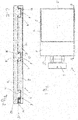
- the lamp housing 1 is shown with a view of the cover 2.
- the lid 2 here has a rectangular shape, comprising two short rectangular sides 3 and two long rectangular sides 4.
- a square light opening 5 is formed, which is arranged in the area of the lid 2 that the light opening 5 over three Edges each have the same distance from the adjacent edge 3, 4 of the cover 2.
- the light opening 5 can be closed here with a material known in the field, for example glass or plastic.
- a wall mounting 6 is arranged in a known manner. Corresponding wall mountings are known in the field, so that these are not explained in more detail.
- FIG 2 is that in Figure 1
- the lamp housing shown is shown in section, with both the cover 2 and the housing 7 being shown.
- the cut is made along a long rectangular side of the lamp housing 1.
- a total of three fasteners / retaining elements 8 are arranged between the cover 2 and the housing 6, two in the corners and another approximately in the middle in the area of the long Rectangular side 4.
- two fastening means / holding means 8 are identical is called a fastening means arranged in a corner and the fastening means 8 arranged in the middle.
- the fastening means / holding means 8 are designed in the area of the cover 2 in the form of a recess 9.
- the recess 9 essentially has a rectangular shape and can be designed as a shaft-shaped recess in the area of a lid edge.
- the recess 9 can, however, also be designed to be open towards the interior of the lamp housing 1.
- a hook 10 is arranged on a side wall of the recess.
- the hook 10 is as in Figure 2 shown, "nose-like", and extends from a corner of the recess obliquely downwards, so that the hook 10 is wider starting from the corner of the recess 10 downwards.
- the hook 10 consequently forms an undercut in the region of the recess 10.
- the hook 10 can be designed with a width which corresponds to the width of the side wall on which the hook 10 is arranged.
- projections 11 are arranged in the region of the housing 7.
- the projections 11 have an angular shape and are formed with a hook 12 on a side wall, that is to say the side wall facing the hook 10 of the recess 9.
- the hook 12 is formed as an extension of the upper side 13 of the projection 11 facing away from the housing and extends along a side wall of the projection 11.
- the projection 11 can be designed with inclined side walls so that the cross-section of the projection resembles the shape of a lying diamond, the inclined surface of the hook 12 also being taken into account.
- the dimensions of the projection 11 are selected in such a way that the projection can be inserted into the recess, ie the clear width of the recess 9 is wider than the width of the projection 11 including hooks.
- the height of the projection 11, in cross section corresponds at most to the depth of the recess 9.
- the third fastening means / holding element 8 which is arranged in the second corner, is designed to be rotated by 180 °.
- the projection 11 arranged on the housing 12 in the region of the second corner consequently inclines away from the other projections 11 in the direction of the second short side 3 'of the rectangle.
- the hook 12 of this projection also points towards the second side of the rectangle 3 ', while the hooks 12 of the other two projections 11 point in the direction of the first short side of the rectangle.
- the recess 9 of the second corner also differs from the other two recesses 9 in that the hook 10 is not formed in one piece with the side wall of the recess, but rather by a screw element, i.e. H. a grub screw 14 is provided and that the recess is also mirror-inverted in cross-section, d. H. the grub screw 14 is arranged on the side wall facing the second short rectangular side 3 '.
- the dimensions of the recess correspond to the dimensions of the other two recesses.
- the grub screw 14 has an inclined surface at its end facing the projection 11; H. it is designed to be pointed, so that the inclined surface of the grub screw 14 can interact with the inclined surface of the hook 12.
- the grub screw 14 is screwed completely into the cover 2 from the second short rectangular side 3 ', so that only the receiving opening 15 of the grub screw 14 is visible from the outside.
- the cover 2 is aligned with the housing 7 in such a way that each projection 11 of the housing is received in a recess 9 in the cover.
- the cover 2 is slightly displaced towards the housing 7, and the two hooks 10, 12 of the recesses 9 or the projections are still arranged next to one another.
- the cover By moving the cover, ie aligning the cover with the circumference of the housing 7, the inclined surfaces of the hooks 10, 12 are then brought into engagement with one another and the hooks slide towards one another on the inclined surface. This movement of the hooks also pulls the cover onto the housing at the same time.
- the cover does not have to be moved manually, but can also be effected or supported by screwing in the grub screw 14.
- the conical lateral surface of the grub screw 14 exerts a pressure on the inclined surface of the hook 12 of the associated projection 11, which pressure is directed in the direction of the first short side 3 of the rectangle. This pressure also moves the inclined surfaces of the other projections 11 towards one another and thus pulls the cover 2 onto the housing 7.
Abstract
Die Erfindung betrifft ein rechteckförmiges Leuchtengehäuse (1) mit zwei sich gegenüberliegenden kurzen (3, 3') und zwei sich gegenüberliegenden langen Rechteckseiten (4, 4'), aufweisend ein Gehäuse (7) und einen das Gehäuse (7) abdeckenden Deckel (2) mit einer Lichtaustrittsöffnung (5), wobei in den Ecken des Gehäuses (7) und des Deckels (2) zusammenwirkende Befestigungsmittel vorgesehen sind. Hierbei sind an den langen Rechteckseiten sowohl des Deckels (2) als auch des Gehäuses (7) zwischen den Ecken hakenförmige ineinandergreifende Haltelemente (8) vorgesehen.The invention relates to a rectangular luminaire housing (1) with two opposite short (3, 3 ') and two opposite long rectangular sides (4, 4'), comprising a housing (7) and a cover (2) covering the housing (7) ) with a light exit opening (5), wherein in the corners of the housing (7) and the cover (2) cooperating fastening means are provided. Here, hook-shaped interlocking retaining elements (8) are provided on the long sides of the rectangle of both the cover (2) and the housing (7) between the corners.
Description
Die vorliegende Erfindung betrifft ein rechteckförmiges Leuchtengehäuse mit zwei sich gegenüberliegenden kurzen und zwei sich gegenüberliegenden langen Rechteckseiten und einer das Gehäuse abdeckende Decke mit einer Lichtaustrittsöffnung, wobei in den Ecken des Gehäuses und des Deckels Befestigungsmittel vorgesehen sind.The present invention relates to a rectangular luminaire housing with two opposing short and two opposing long rectangular sides and a cover covering the housing with a light exit opening, fastening means being provided in the corners of the housing and the cover.
Aus dem Stand der Technik sind unterschiedlichste Mittel bekannt, um einen Deckel an einem Gehäuse zu befestigen. Beispielsweise kann der Deckel über eine Dichtung mit einem Gehäuse verbunden werden, wobei die Befestigung über Schrauben erfolgt, die zumeist in den Ecken angeordnet sind. Hierbei müssen die Schrauben in der Regel kreuzweise angezogen werden, um einem Verziehen des Deckels entgegenzuwirken. Zudem ist es auch bekannt, zusätzliche Schrauben zwischen den Ecken vorzusehen. Gleichermaßen ist es bekannt, das Gehäuse und den Deckel mit Riegeln und den Riegeln zugeordneten Freisparungen auszubilden, um eine lösbare Verbindung zu realisieren. Entsprechende Gehäuse sind aus unterschiedlichsten Gebieten bekannt, werden jedoch nicht im Bereich von Leuchtengehäusen eingesetzt.A wide variety of means are known from the prior art for attaching a cover to a housing. For example, the cover can be connected to a housing by means of a seal, the fastening being carried out by means of screws, which are mostly arranged in the corners. As a rule, the screws have to be tightened crosswise in order to counteract any distortion of the cover. It is also known to provide additional screws between the corners. It is also known to design the housing and the cover with latches and recesses assigned to the latches in order to realize a detachable connection. Corresponding housings are known from a wide variety of fields, but are not used in the field of lamp housings.
In Bezug auf Leuchtengehäuse ist es bekannt, Dichtungen zwischen einem Deckel und einem Gehäuse zu verwenden, um die Bestandteile der Leuchte vor Feuchtigkeit und/oder Verschmutzung zu schützen.With regard to lamp housings, it is known to use seals between a cover and a housing in order to protect the components of the lamp from moisture and / or contamination.
Aufgabe der vorliegenden Erfindung ist es eine wirkungsvolle Verbindung zwischen Deckel und Gehäuse bereitzustellen, bei der die Gehäuseelemente zuverlässig miteinander verbunden werden und die sich einfach montieren lässt und gleichzeitig, sofern eine Dichtung vorgesehen ist, eine zuverlässige Abdichtung der Leuchte gewährleistet.The object of the present invention is to provide an effective connection between the cover and the housing in which the housing elements are reliably connected to one another and which is easy to assemble and at the same time, if a seal is provided, ensures reliable sealing of the lamp.
Diese Aufgabe wird durch ein rechteckförmiges Leuchtengehäuse mit zwei sich gegenüberliegenden kurzen und zwei sich gegenüberliegenden langen Rechteckseiten und einen das Gehäuse abdeckenden Deckel mit einer Lichtaustrittsöffnung, wobei in den Ecken des Gehäuses und des Deckels zusammenwirkende Befestigungsmittel vorgesehen sind, dadurch gelöst, dass an den langen Rechteckseiten sowohl des Deckels als auch des Gehäuses zwischen den Ecken hakenförmige ineinandergreifende Haltelemente vorgesehen sind.This object is achieved by a rectangular luminaire housing with two opposing short and two opposing long rectangular sides and a cover covering the housing with a light exit opening, whereby fastening means cooperating in the corners of the housing and the cover are provided, in that on the long rectangular sides both the cover and the housing between the corners hook-shaped interlocking retaining elements are provided.
Die vorliegende Erfindung stellt somit ein Leuchtengehäuse zur Verfügung welches eine besonders gute und gleichmäßige Fixierung des Deckels an dem Gehäuse gewährleistet. Durch den Einsatz von hakenförmigen ineinandergreifenden Halteelementen ist es möglich auf weitere Befestigungsmittel zu verzichten. Hierbei wirken die hakenförmigen Halteelemente zwischen dem Deckel und dem Gehäuse, so dass diese von außen nicht sichtbar sind. Hierdurch ist es möglich ein Gehäuse bereitzustellen, welches sich durch besonders klare Linien auszeichnet. Ferner können die hakenförmigen Halteelemente ohne zusätzliche Werkzeuge beim Verbinden des Deckels mit dem Gehäuse zusammenwirken.The present invention thus provides a lamp housing which ensures particularly good and uniform fixing of the cover to the housing. By the use of hook-shaped interlocking retaining elements makes it possible to dispense with further fastening means. Here, the hook-shaped holding elements act between the cover and the housing, so that they are not visible from the outside. This makes it possible to provide a housing which is characterized by particularly clear lines. Furthermore, the hook-shaped holding elements can interact without additional tools when connecting the cover to the housing.
Gemäß der vorliegenden Erfindung können die Befestigungselemente zweier Ecken ebenfalls als jeweils hakenförmige ineinandergreifende Haltelemente ausgebildet sein. Hierdurch wird die Gesamtoptik des Gehäuses angepasst und gleichzeitig die Fixierung des Deckels an dem Gehäuse vereinfacht. Die verschiedenen eingesetzten hakenförmigen Halteelemente können gleichzeitig, während eines einzigen Verbindungsschrittes miteinander in Kontakt gebracht werden. Hierdurch verringert sich die Montagezeit des Gehäuses erheblich.According to the present invention, the fastening elements of two corners can also be designed as hook-shaped interlocking holding elements. This adapts the overall appearance of the housing and, at the same time, simplifies the fixing of the cover on the housing. The various hook-shaped holding elements used can be brought into contact with one another at the same time during a single connecting step. This considerably reduces the assembly time for the housing.
Gemäß einer besonders bevorzugten Ausführungsform können die hakenförmigen Halteelemente im Bereich des Deckels und/oder des Gehäuses in einer Vertiefung angeordnet sein. Die Anordnung der hakenförmigen Halteelemente in einer Vertiefung stellt sicher, dass diese vollumfänglich geschützt sind. Gleichzeitig wird die Montage des Deckels am Gehäuse vereinfacht, da die Vertiefungen gezielt den Bereich der hakenförmigen Halteelemente angeben, sodass die beiden Elemente, Deckel und Gehäuse, bereits in der richtigen Position aufeinandergesetzt werden können.According to a particularly preferred embodiment, the hook-shaped holding elements can be arranged in a recess in the area of the cover and / or the housing. The arrangement of the hook-shaped retaining elements in a recess ensures that they are fully protected. At the same time, the assembly of the cover on the housing is simplified, since the recesses specifically indicate the area of the hook-shaped holding elements, so that the two elements, cover and housing, can already be placed on top of one another in the correct position.
Hierbei hat es sich besonders bewährt, wenn die Vertiefung zumindest an der Außenseite des Deckels und/oder des Gehäuses verschlossen ist. Gleichzeitig kann die Vertiefung auch schachtartig in der Seitenwand des Gehäuses oder in einem Deckelrand ausgebildet sein, sodass die Halteelemente weder an der Außenseite noch der Innenseite des Gehäuses oder Deckels vortreten. Sofern der Deckel über seine gesamte Fläche eine im wesentlichen gleichbleibende Materialstärke aufweist, kann die Vertiefung auch einfach schachtartig in dem Deckel ausgebildet sein. Diese Ausführungsform unterstützt insbesondere die Führung der hakenförmigen Halteelemente beim Eingriff ineinander. Gleichzeitig wird sichergestellt, dass die Halteelemente bzw. Befestigungselemente innerhalb des Gehäuses und des Deckels angeordnet sind, sodass von außen keine Befestigungsmittel sichtbar sind.It has proven particularly useful if the recess is closed at least on the outside of the cover and / or the housing. At the same time, the recess can also be formed like a shaft in the side wall of the housing or in a cover edge, so that the holding elements protrude neither on the outside nor on the inside of the housing or cover. If the cover has an essentially constant material thickness over its entire surface, the recess can also simply be designed like a shaft in the cover. This embodiment supports in particular the guidance of the hook-shaped holding elements when they engage one another. At the same time, it is ensured that the holding elements or fastening elements are arranged within the housing and the cover so that no fastening means are visible from the outside.
Gemäß einer anderen bevorzugten Ausführungsform kann jedes hakenförmige Halteelement im Bereich des Deckels in einer Vertiefung ausgebildet sein, wobei ein Haken im Bereich einer Seitenwand angeordnet ist. Auch diese Ausführungsform erleichtert die Montage des Deckels auf dem Gehäuse, da Deckel einfach mit dem Gehäuse verbunden werden kann. Zudem ermöglicht die Anordnung der Haken im Bereich einer Seitenwand der Vertiefung ein automatisches Eingreifen zweier Haken ineinander, wenn der Deckel leicht gegen das Gehäuse verschoben wird.According to another preferred embodiment, each hook-shaped holding element can be formed in a recess in the area of the cover, a hook being arranged in the area of a side wall. This embodiment also facilitates the assembly of the cover on the housing, as the cover can easily be connected to the housing. In addition, the arrangement of the hooks in the area of a side wall of the recess enables two hooks to automatically engage one another when the cover is moved slightly against the housing.
Eine andere bevorzugte Ausführungsform kann vorsehen, dass jedes hakenförmige Halteelement im Bereich des Gehäuses in Verlängerung der Seitenwände als Vorsprung ausgebildet ist, der in die Vertiefung hineinragt und mit dem Haken der Vertiefung zusammenwirkt. Hierbei weist der Vorsprung eine Dicke auf, die geringer ist als die Dicke der Seitenwand um ein problemloses Eingreifen in die Vertiefung im Bereich des Deckels zu gewährleisten, ohne dass die Halteelemente von außen sichtbar sind. Werden der Deckel und das Gehäuse miteinander verbunden, können die Vorsprünge einfach in die Vertiefungen im Bereich des Deckels eingeführt werden und stellen somit eine Führung bereit. Ferner ist die Anordnung der hakenförmigen Halteelemente als Verlängerung der Seitenwände bezüglich der Herstellung besonders einfach.Another preferred embodiment can provide that each hook-shaped holding element in the area of the housing is designed as a projection in the extension of the side walls, which protrudes into the recess and interacts with the hook of the recess. In this case, the projection has a thickness which is less than the thickness of the side wall in order to ensure problem-free engagement in the recess in the area of the cover without the holding elements being visible from the outside. If the cover and the housing are connected to one another, the projections can simply be inserted into the recesses in the region of the cover and thus provide a guide. Furthermore, the arrangement of the hook-shaped holding elements as an extension of the side walls is particularly simple with regard to production.
Eine besonders einfache Ausführungsform kann vorsehen, dass der Vorsprung an einer dem Haken der Vertiefung gegenüberliegenden Seitenwand mit einem Haken ausgebildet ist, der mit dem Haken der Vertiefung zusammenwirkt. Beim Einführen des Vorsprungs in die Vertiefung werden die Haken automatisch miteinander ausgerichtet und können einfach zusammengeführt werden.A particularly simple embodiment can provide that the projection is formed on a side wall opposite the hook of the recess with a hook which cooperates with the hook of the recess. When the projection is inserted into the recess, the hooks are automatically aligned with one another and can simply be brought together.
Gemäß einer besonders bevorzugten Ausführungsform können der Haken der Vertiefung und der Haken des Vorsprungs mit korrespondierenden schrägen Flächen ausgebildet sein, die im Einsatz zusammenwirken. Durch leichtes Verschieben des Deckels gegen das Gehäuse kommen die beiden Haken im Bereich der schrägen Flächen miteinander in Kontakt, und können somit leicht gegeneinander verschoben werden. Hierdurch wird eine besonders sichere Fixierung des Deckels an dem Gehäuse erzielt.According to a particularly preferred embodiment, the hook of the recess and the hook of the projection can be designed with corresponding inclined surfaces which interact in use. By slightly moving the cover against the housing, the two hooks come into contact with one another in the area of the inclined surfaces and can thus be easily moved against one another. This achieves a particularly secure fixation of the cover on the housing.
Hierbei kann gemäß einer weiteren bevorzugten Ausführungsform vorgesehen sein, dass durch ein seitliches Verschieben des Deckels gegen das Gehäuse die Hakenelemente in der Vertiefung und des Vorsprungs zusammenwirken, wodurch sich der Deckel gegen das Gehäuse zieht. Durch die Bereitstellung der schrägen Flächen werden die Haken durch die Verschiebung immer weiter in Kontakt gebracht, und hierdurch der Deckel und das Gehäuse aneinander gezogen. Da nicht nur an den Ecken, sondern auch im Bereich der langen Rechteckseiten Halteelemente vorgesehen sind, kann hierdurch sichergestellt werden, dass über den gesamten Bereich des Gehäuses eine vollständige Dichtung zwischen Deckel und Gehäuse erzielt wird. Gleichzeitig wird ausgeschlossen, dass sich der Deckel in Bezug auf das Gehäuse verformt. Hierbei kann die Anzahl zusätzliche Halteelemente an der langen Rechteckseite je nach Größe des Gehäuses bestimmt werden.Here, according to a further preferred embodiment, it can be provided that the hook elements in the recess and the projection interact by a lateral displacement of the cover against the housing, whereby the cover pulls against the housing. As a result of the provision of the inclined surfaces, the hooks are brought more and more into contact by the displacement, and the cover and the housing are thereby drawn towards one another. Since holding elements are provided not only at the corners, but also in the area of the long sides of the rectangle, this ensures that over the entire area of the housing a complete seal between cover and housing is achieved. At the same time, it is impossible for the cover to deform in relation to the housing. The number of additional retaining elements on the long side of the rectangle can be determined depending on the size of the housing.
Gemäß noch einer anderen bevorzugten Ausführungsform können die Befestigungselemente beider Ecken als jeweils hakenförmige ineinandergreifende Halteelemente ausgebildet sein, wobei die Wirkrichtung der hakenförmigen Halteelemente der Befestigungselemente der zweiten Ecke um 180° zur Wirkrichtung der ersten Ecke gedreht ist. Die hackenförmigen Halteelemente dieser zwei Ecken sind folglich spiegelbildlich zueinander angeordnet. Diese Ausführungsform dient ebenfalls der Vereinfachung der Montage.According to yet another preferred embodiment, the fastening elements of both corners can be designed as hook-shaped interlocking retaining elements, the direction of action of the hook-shaped retaining elements of the fastening elements of the second corner being rotated by 180 ° to the direction of action of the first corner. The hook-shaped holding elements of these two corners are consequently arranged in mirror image to one another. This embodiment also serves to simplify assembly.
Hierbei hat es sich bewährt, wenn das um 180° gedrehte hackenförmige Halteelement, d. h. der Haken in der Seitenwand der Vertiefung der zweiten Ecke durch ein Schraubenelement bereitgestellt wird. Ein entsprechendes Schraubenelement, vorzugsweise eine Madenschraube, die einfach von der Außenseite, d. h. der kurzen Rechteckseite des Deckels eingeschraubt werden kann, übernimmt hierbei die Aufgabe des Hakens der Vertiefung. Hierbei weist das Schraubenelement vorzugsweise an seiner Spitze eine gleichermäßig über den Umfang ausgebildete Schrägfläche auf, die mit dem Haken des Vorsprungs kontinuierlich zusammenwirkt. Durch das Einschrauben der Madenschraube wird diese nicht nur in Kontakt mit dem korrespondierenden Vorsprung gebracht, sondern gleichzeitig auf die anderen zusammenwirkenden Halteelemente ein Druck ausgeübt, durch welchen der Deckel und das Gehäuse in die finale Position zueinander gezogen werden.Here, it has proven useful if the hook-shaped holding element rotated by 180 °, d. H. the hook is provided in the side wall of the recess of the second corner by a screw member. A corresponding screw element, preferably a grub screw, which can be easily removed from the outside, i.e. H. the short rectangular side of the lid can be screwed in, takes on the task of the hook of the recess. In this case, the screw element preferably has at its tip an inclined surface which is formed uniformly over the circumference and which interacts continuously with the hook of the projection. By screwing in the grub screw, it is not only brought into contact with the corresponding projection, but at the same time a pressure is exerted on the other cooperating holding elements, by means of which the cover and the housing are pulled into the final position with respect to one another.
Ferner kann vorgesehen sein, dass die in den Vertiefungen angeordneten Haken der Ecken an der Seitenwand, die der kurzen Rechteckseite zugewandt bzw. benachbart ist, angeordnet sind. Auf diese Weise wird sichergestellt, dass die Madenschraube von außen eingeschraubt werden kann. Es ist festzuhalten, dass eine entsprechende Madenschraube von der Seite des Gehäuses bzw. des Deckels eingeschraubt werden kann, die im Einsatz beispielsweise einer Wand zugewandt ist, sodass diese Madenschraube nicht weiter auffällt.Furthermore, it can be provided that the hooks of the corners which are arranged in the depressions are arranged on the side wall which faces or is adjacent to the short side of the rectangle. This ensures that the grub screw can be screwed in from the outside. It should be noted that a corresponding grub screw can be screwed in from the side of the housing or the cover which, in use, faces a wall, for example, so that this grub screw is no longer noticeable.
Gemäß einer anderen bevorzugten Ausführungsform kann die Breite des Vorsprungs kleiner sein als die lichte Breite der Vertiefung, um sicherzustellen, dass der Vorsprung problemlos in die Vertiefung eingeführt werden kann. Hierbei bezieht sich die Angabe auf die Breite des Vorsprungs inklusive des daran angeordneten Hakens.According to another preferred embodiment, the width of the projection can be smaller than the clear width of the recess in order to ensure that the projection can be inserted into the recess without any problems. Here, the specification relates to the width of the projection including the hook arranged on it.
Die vorliegende Erfindung stellt folglich eine Befestigungsmöglichkeit zur Verfügung, die sich für Gehäuse beliebiger Größe eignet, auch großflächige und lang gestreckte Gehäuse, wobei eine sichere Dichtung über das ganze Gehäuse erzielt werden kann. Da die Befestigungsmittel bzw. Halteelemente im Inneren des Gehäuses, vorzugsweise zwischen Gehäuserand und Deckel angeordnet sind, sind diese von außen nicht sichtbar, sodass sich das Gehäuse durch besonders klare Linien auszeichnet. Gleichzeitig kann sichergestellt werden, dass das Gehäuse nicht von außen manipuliert wird. Entsprechende Halteelemente bzw. Befestigungselemente eignen sich zudem für besonders gut für flache Gehäuse, bei denen in der Regel aufgrund der Abmessungen der Einsatz von Schrauben zur Befestigung unmöglich ist.The present invention consequently provides a means of fastening which is suitable for housings of any size, including large-area and elongated housings, it being possible to achieve a secure seal over the entire housing. Since the fastening means or holding elements are arranged inside the housing, preferably between the edge of the housing and the cover, they are not visible from the outside, so that the housing is characterized by particularly clear lines. At the same time, it can be ensured that the housing cannot be manipulated from the outside. Corresponding holding elements or fastening elements are also particularly suitable for flat housings, in which the use of screws for fastening is usually impossible due to the dimensions.
Die vorliegende Erfindung wird im Folgenden anhand eines bevorzugten Ausführungsbeispiels näher erläutert. Es zeigt:
Figur 1- eine Aufsicht auf ein erfindungsgemäßes Leuchtengehäuse und
Figur 2- einen Schnitt durch das in
Figur 1
- Figure 1
- a plan view of an inventive lamp housing and
- Figure 2
- a section through the in
Figure 1 luminaire housing shown along the line EE.
In
An dem von der Lichtöffnung 5 abgewandten Ende des Leuchtengehäuses 1 ist eine Wandbefestigung 6 auf bekannte Art und Weise angeordnet. Entsprechende Wandbefestigungen sind auf dem Gebiet bekannt, sodass diese nicht näher erläutert werden.At the end of the
In
Die Befestigungsmittel/Haltemittel 8 sind im Bereich des Deckels 2 in Form einer Vertiefung 9 ausgebildet. Die Vertiefung 9 weist im Wesentlichen eine rechteckige Form auf und kann als eine schachtförmige Vertiefung im Bereich eines Deckelrandes ausgebildet sein. Die Vertiefung 9 kann jedoch auch zum Innenraum des Leuchtengehäuses 1 hin geöffnet ausgebildet sein.The fastening means / holding means 8 are designed in the area of the
An einer Seitenwand der Vertiefung ist ein Haken 10 angeordnet. Der Haken 10 ist, wie in
Den Vertiefungen 9 gegenüberliegend sind im Bereich des Gehäuses 7 Vorsprünge 11 angeordnet. Die Vorsprünge 11 weisen eine eckige Form auf und sind an einer Seitenwand, das heißt der dem Haken 10 der Vertiefung 9 zugewandten Seitenwand, mit einem Haken 12 ausgebildet.Opposite the
Der Haken 12 ist in Verlängerung der vom Gehäuse abgewandten Oberseite 13 des Vorsprunges 11 ausgebildet und erstreckt sich entlang einer Seitenwand des Vorsprunges 11. Hierbei ist die Unterseite des Hakens 12, das heißt die zwischen dem Gehäuse 7 und der Oberseite 13 des Vorsprunges 11 angeordnete, sich auf den Vorsprung zu erstreckende Unterseite des Hakens 12 unter einer vorbestimmten Schräge ausgebildet.The
Aus
Hinsichtlich des Vorsprunges 11 ist festzuhalten, dass dieser mit schrägen Seitenwänden ausgebildet sein kann, sodass der Vorsprung im Querschnitt der Form einer liegenden Raute ähnelt, wobei die schräge Fläche des Hakens 12 mitberücksichtigt wird. Die Abmessungen des Vorsprunges 11 sind solchermaßen gewählt, dass der Vorsprung in die Vertiefung eingeführt werden kann, d. h. die lichte Breite der Vertiefung 9 ist breiter als die Breite des Vorsprunges 11 einschließlich Haken. Ferner entspricht die Höhe des Vorsprunges 11, im Querschnitt, höchstens der Tiefe der Vertiefung 9.With regard to the projection 11, it should be noted that it can be designed with inclined side walls so that the cross-section of the projection resembles the shape of a lying diamond, the inclined surface of the
Im Gegensatz zu den vorab beschriebenen Befestigungsmitteln/Halteelementen 8, ist das dritte Befestigungsmittel/Halteelemente 8, das in der zweiten Ecke angeordnet ist, um 180° gedreht ausgebildet. Der an dem Gehäuse 12 im Bereich der zweiten Ecke angeordnete Vorsprung 11 neigt sich folglich von den anderen Vorsprüngen 11 weg in Richtung der zweiten kurzen Rechteckseite 3'. Gleichermaßen zeigt auch der Haken 12 dieses Vorsprunges zu der zweiten Rechteckseite 3', während die Haken 12 der anderen beiden Vorsprünge 11 in Richtung der ersten kurzen Rechteckseite weisen.In contrast to the fastening means / holding
Sämtliche andere Merkmale der Vorsprünge 11, mit Ausnahme der Ausrichtung sind identisch.All other features of the projections 11, with the exception of the orientation, are identical.
Auch die Vertiefung 9 der zweiten Ecke unterscheidet dahingehend von den andern beiden Vertiefungen 9, dass der Haken 10 nicht einstückig mit der Seitenwand der Vertiefung ausgebildet ist, sondern von einem Schraubelement, d. h. einer Madenschraube 14 bereitgestellt wird und dass auch die Vertiefung im Querschnitt spiegelverkehrt ausgebildet ist, d. h. die Madenschraube 14 ist an der der zweiten kurzen Rechteckseite 3' zugewandten Seitenwand angeordnet. Die Abmessungen der Vertiefung entsprechen den Abmessungen der anderen beiden Vertiefungen.The
Hierbei weist die Madenschraube 14 an ihrem dem Vorsprung 11 zugewandten Ende eine schräge Fläche auf, d. h. sie ist angespitzt ausgebildet, sodass die schräge Fläche der Madenschraube 14 mit der schrägen Fläche des Hakens 12 zusammenwirken kann.Here, the
Wie in
Um das Leuchtengehäuse 1 zu verschließen, wird der Deckel 2 so zum Gehäuse 7 ausgerichtet, dass jeder Vorsprung 11 des Gehäuses in einer Vertiefung 9 des Deckels aufgenommen wird. In diesem Zustand ist der Deckel 2 leicht zum Gehäuse 7 verschoben, und die beiden Haken 10, 12 der Vertiefungen 9 bzw. der Vorsprünge sind noch nebeneinander angeordnet. Durch Verschieben des Deckels, d. h. Ausrichten des Deckels zum Umfang des Gehäuses 7 werden dann die schrägen Flächen der Haken 10,12 in Eingriff miteinander gebracht und die Haken schieben sich auf der schrägen Fläche aufeinander zu. Durch diese Bewegung der Haken wird auch gleichzeitig der Deckel an das Gehäuse gezogen.In order to close the
Das Verschieben des Deckels muss hierbei nicht manuell erfolgen, sondern kann auch durch das Einschrauben der Madenschraube 14 bewirkt bzw. unterstützt werden. Die konische Mantelfläche der Madenschraube 14 übt auf die schräge Fläche des Hakens 12 des zugeordneten Vorsprunges 11 einen Druck aus, der in Richtung der ersten kurzen Rechteckseite 3 gerichtet ist. Durch diesen Druck werden auch die schrägen Flächen der anderen Vorsprünge 11 aufeinander zu bewegt und somit der Deckel 2 an das Gehäuse 7 gezogen.The cover does not have to be moved manually, but can also be effected or supported by screwing in the
Claims (13)
dadurch gekennzeichnet, dass
an den langen Rechteckseiten (4) sowohl des Deckels (2) als auch des Gehäuses (7) zwischen den Ecken hakenförmige ineinandergreifende Haltelemente (8) vorgesehen sind.Rectangular lamp housing (1) with two opposite short (3, 3 ') and two opposite long (4) rectangular sides and a cover (2) covering the housing (7) with a light outlet opening (5), with in the corners of the housing (7) and the cover (2) cooperating fastening means are provided,
characterized in that
on the long rectangular sides (4) of both the cover (2) and the housing (7) between the corners hook-shaped interlocking retaining elements (8) are provided.
Priority Applications (1)
| Application Number | Priority Date | Filing Date | Title |
|---|---|---|---|
| EP19173079.5A EP3736488B1 (en) | 2019-05-07 | 2019-05-07 | Rectangular housing |
Applications Claiming Priority (1)
| Application Number | Priority Date | Filing Date | Title |
|---|---|---|---|
| EP19173079.5A EP3736488B1 (en) | 2019-05-07 | 2019-05-07 | Rectangular housing |
Publications (2)
| Publication Number | Publication Date |
|---|---|
| EP3736488A1 true EP3736488A1 (en) | 2020-11-11 |
| EP3736488B1 EP3736488B1 (en) | 2021-07-21 |
Family
ID=66554132
Family Applications (1)
| Application Number | Title | Priority Date | Filing Date |
|---|---|---|---|
| EP19173079.5A Active EP3736488B1 (en) | 2019-05-07 | 2019-05-07 | Rectangular housing |
Country Status (1)
| Country | Link |
|---|---|
| EP (1) | EP3736488B1 (en) |
Citations (6)
| Publication number | Priority date | Publication date | Assignee | Title |
|---|---|---|---|---|
| FR2535438A1 (en) * | 1982-10-29 | 1984-05-04 | Eclairage Tech | Globe for lighting equipment |
| EP0159145A1 (en) * | 1984-03-15 | 1985-10-23 | Eterna Lighting Ltd. | Lighting unit |
| EP0392217A1 (en) * | 1989-03-25 | 1990-10-17 | ABB CEAG Licht- und Stromversorgungstechnik GmbH | Elongated light fixture |
| EP1816420A2 (en) * | 2006-02-06 | 2007-08-08 | BSH Bosch und Siemens Hausgeräte GmbH | Illumination assembly for a household appliance |
| EP2940380A1 (en) * | 2014-04-29 | 2015-11-04 | Zumtobel Lighting GmbH | Seal |
| US20180224090A1 (en) * | 2015-09-09 | 2018-08-09 | Feng Li | Bolt locking structure for waterproof LED lamp |
-
2019
- 2019-05-07 EP EP19173079.5A patent/EP3736488B1/en active Active
Patent Citations (6)
| Publication number | Priority date | Publication date | Assignee | Title |
|---|---|---|---|---|
| FR2535438A1 (en) * | 1982-10-29 | 1984-05-04 | Eclairage Tech | Globe for lighting equipment |
| EP0159145A1 (en) * | 1984-03-15 | 1985-10-23 | Eterna Lighting Ltd. | Lighting unit |
| EP0392217A1 (en) * | 1989-03-25 | 1990-10-17 | ABB CEAG Licht- und Stromversorgungstechnik GmbH | Elongated light fixture |
| EP1816420A2 (en) * | 2006-02-06 | 2007-08-08 | BSH Bosch und Siemens Hausgeräte GmbH | Illumination assembly for a household appliance |
| EP2940380A1 (en) * | 2014-04-29 | 2015-11-04 | Zumtobel Lighting GmbH | Seal |
| US20180224090A1 (en) * | 2015-09-09 | 2018-08-09 | Feng Li | Bolt locking structure for waterproof LED lamp |
Also Published As
| Publication number | Publication date |
|---|---|
| EP3736488B1 (en) | 2021-07-21 |
Similar Documents
| Publication | Publication Date | Title |
|---|---|---|
| EP0030290B1 (en) | Drawer | |
| DE4101363C1 (en) | ||
| DE2436844C2 (en) | Fastening means for a fitting part on metal or plastic hollow profiles, in particular on door or window sashes and frames | |
| DE4201570C2 (en) | Actuator | |
| EP3736488B1 (en) | Rectangular housing | |
| DE2648089C2 (en) | Blanking plate for device cover | |
| DE3214915C2 (en) | ||
| DE102018102488A1 (en) | Arrangement for positioning a flat part on a control cabinet frame and a corresponding method | |
| DE102014016899B3 (en) | Lifting-lowering hinge and door with lifting-lowering hinge | |
| DE2907049A1 (en) | Screwed chassis electrical component support - has lugs around component adjusted along screw threads to clamp against chassis | |
| DE202018000700U1 (en) | Holder for flowers and decorative goods on window and door wings | |
| DE10313842B4 (en) | cabinet door | |
| EP0270802A1 (en) | Device for sealing and simultaneously mechanically locking a cover onto an apparatus | |
| DE7025049U (en) | CONNECTORS FOR FASTENING A FRAME TO A WALL TONGS. | |
| DE102016123321A1 (en) | Shutter box | |
| DE2839974A1 (en) | Frameless picture holder with front and back plates - has special retaining clips allowing easy removal of cover without damage | |
| DE3609992A1 (en) | Door case for surrounding metal cases | |
| DE7731551U1 (en) | Dust-tight housing, in particular for electrical systems | |
| DE2426694C3 (en) | Radiator cladding | |
| DE4104340A1 (en) | PROFILE JOINT, IN PARTICULAR FOR GLASS PANELS WITH LARGE DIMENSIONS | |
| DE1797571C3 (en) | Frame for slide film pictures | |
| DE10032478A1 (en) | shower enclosure | |
| AT397142B (en) | DEVICE FOR CLOSING OPENINGS IN A WALL | |
| DE4013441A1 (en) | Guide for locking bars esp. of switchgear cubicle - has foot prevented from slipping out of hole in door in which it can rotate freely | |
| DE3217413A1 (en) | Device for fastening threshold rails to wooden frames |
Legal Events
| Date | Code | Title | Description |
|---|---|---|---|
| PUAI | Public reference made under article 153(3) epc to a published international application that has entered the european phase |
Free format text: ORIGINAL CODE: 0009012 |
|
| STAA | Information on the status of an ep patent application or granted ep patent |
Free format text: STATUS: REQUEST FOR EXAMINATION WAS MADE |
|
| 17P | Request for examination filed |
Effective date: 20190507 |
|
| AK | Designated contracting states |
Kind code of ref document: A1 Designated state(s): AL AT BE BG CH CY CZ DE DK EE ES FI FR GB GR HR HU IE IS IT LI LT LU LV MC MK MT NL NO PL PT RO RS SE SI SK SM TR |
|
| AX | Request for extension of the european patent |
Extension state: BA ME |
|
| RIC1 | Information provided on ipc code assigned before grant |
Ipc: F21V 17/14 20060101ALI20210302BHEP Ipc: F21S 8/00 20060101ALN20210302BHEP Ipc: F21V 15/01 20060101AFI20210302BHEP Ipc: F21V 17/00 20060101ALN20210302BHEP Ipc: F21V 31/00 20060101ALN20210302BHEP |
|
| GRAP | Despatch of communication of intention to grant a patent |
Free format text: ORIGINAL CODE: EPIDOSNIGR1 |
|
| STAA | Information on the status of an ep patent application or granted ep patent |
Free format text: STATUS: GRANT OF PATENT IS INTENDED |
|
| INTG | Intention to grant announced |
Effective date: 20210412 |
|
| GRAS | Grant fee paid |
Free format text: ORIGINAL CODE: EPIDOSNIGR3 |
|
| GRAA | (expected) grant |
Free format text: ORIGINAL CODE: 0009210 |
|
| STAA | Information on the status of an ep patent application or granted ep patent |
Free format text: STATUS: THE PATENT HAS BEEN GRANTED |
|
| AK | Designated contracting states |
Kind code of ref document: B1 Designated state(s): AL AT BE BG CH CY CZ DE DK EE ES FI FR GB GR HR HU IE IS IT LI LT LU LV MC MK MT NL NO PL PT RO RS SE SI SK SM TR |
|
| REG | Reference to a national code |
Ref country code: GB Ref legal event code: FG4D Free format text: NOT ENGLISH |
|
| REG | Reference to a national code |
Ref country code: HK Ref legal event code: DE Ref document number: 40040499 Country of ref document: HK Ref country code: CH Ref legal event code: EP |
|
| REG | Reference to a national code |
Ref country code: DE Ref legal event code: R096 Ref document number: 502019001838 Country of ref document: DE |
|
| REG | Reference to a national code |
Ref country code: AT Ref legal event code: REF Ref document number: 1412913 Country of ref document: AT Kind code of ref document: T Effective date: 20210815 |
|
| REG | Reference to a national code |
Ref country code: IE Ref legal event code: FG4D Free format text: LANGUAGE OF EP DOCUMENT: GERMAN |
|
| REG | Reference to a national code |
Ref country code: LT Ref legal event code: MG9D |
|
| REG | Reference to a national code |
Ref country code: NL Ref legal event code: MP Effective date: 20210721 |
|
| PG25 | Lapsed in a contracting state [announced via postgrant information from national office to epo] |
Ref country code: LT Free format text: LAPSE BECAUSE OF FAILURE TO SUBMIT A TRANSLATION OF THE DESCRIPTION OR TO PAY THE FEE WITHIN THE PRESCRIBED TIME-LIMIT Effective date: 20210721 Ref country code: BG Free format text: LAPSE BECAUSE OF FAILURE TO SUBMIT A TRANSLATION OF THE DESCRIPTION OR TO PAY THE FEE WITHIN THE PRESCRIBED TIME-LIMIT Effective date: 20211021 Ref country code: HR Free format text: LAPSE BECAUSE OF FAILURE TO SUBMIT A TRANSLATION OF THE DESCRIPTION OR TO PAY THE FEE WITHIN THE PRESCRIBED TIME-LIMIT Effective date: 20210721 Ref country code: NL Free format text: LAPSE BECAUSE OF FAILURE TO SUBMIT A TRANSLATION OF THE DESCRIPTION OR TO PAY THE FEE WITHIN THE PRESCRIBED TIME-LIMIT Effective date: 20210721 Ref country code: NO Free format text: LAPSE BECAUSE OF FAILURE TO SUBMIT A TRANSLATION OF THE DESCRIPTION OR TO PAY THE FEE WITHIN THE PRESCRIBED TIME-LIMIT Effective date: 20211021 Ref country code: PT Free format text: LAPSE BECAUSE OF FAILURE TO SUBMIT A TRANSLATION OF THE DESCRIPTION OR TO PAY THE FEE WITHIN THE PRESCRIBED TIME-LIMIT Effective date: 20211122 Ref country code: ES Free format text: LAPSE BECAUSE OF FAILURE TO SUBMIT A TRANSLATION OF THE DESCRIPTION OR TO PAY THE FEE WITHIN THE PRESCRIBED TIME-LIMIT Effective date: 20210721 Ref country code: FI Free format text: LAPSE BECAUSE OF FAILURE TO SUBMIT A TRANSLATION OF THE DESCRIPTION OR TO PAY THE FEE WITHIN THE PRESCRIBED TIME-LIMIT Effective date: 20210721 Ref country code: RS Free format text: LAPSE BECAUSE OF FAILURE TO SUBMIT A TRANSLATION OF THE DESCRIPTION OR TO PAY THE FEE WITHIN THE PRESCRIBED TIME-LIMIT Effective date: 20210721 Ref country code: SE Free format text: LAPSE BECAUSE OF FAILURE TO SUBMIT A TRANSLATION OF THE DESCRIPTION OR TO PAY THE FEE WITHIN THE PRESCRIBED TIME-LIMIT Effective date: 20210721 |
|
| PG25 | Lapsed in a contracting state [announced via postgrant information from national office to epo] |
Ref country code: PL Free format text: LAPSE BECAUSE OF FAILURE TO SUBMIT A TRANSLATION OF THE DESCRIPTION OR TO PAY THE FEE WITHIN THE PRESCRIBED TIME-LIMIT Effective date: 20210721 Ref country code: LV Free format text: LAPSE BECAUSE OF FAILURE TO SUBMIT A TRANSLATION OF THE DESCRIPTION OR TO PAY THE FEE WITHIN THE PRESCRIBED TIME-LIMIT Effective date: 20210721 Ref country code: GR Free format text: LAPSE BECAUSE OF FAILURE TO SUBMIT A TRANSLATION OF THE DESCRIPTION OR TO PAY THE FEE WITHIN THE PRESCRIBED TIME-LIMIT Effective date: 20211022 |
|
| REG | Reference to a national code |
Ref country code: DE Ref legal event code: R097 Ref document number: 502019001838 Country of ref document: DE |
|
| PG25 | Lapsed in a contracting state [announced via postgrant information from national office to epo] |
Ref country code: DK Free format text: LAPSE BECAUSE OF FAILURE TO SUBMIT A TRANSLATION OF THE DESCRIPTION OR TO PAY THE FEE WITHIN THE PRESCRIBED TIME-LIMIT Effective date: 20210721 |
|
| PLBE | No opposition filed within time limit |
Free format text: ORIGINAL CODE: 0009261 |
|
| STAA | Information on the status of an ep patent application or granted ep patent |
Free format text: STATUS: NO OPPOSITION FILED WITHIN TIME LIMIT |
|
| PG25 | Lapsed in a contracting state [announced via postgrant information from national office to epo] |
Ref country code: SM Free format text: LAPSE BECAUSE OF FAILURE TO SUBMIT A TRANSLATION OF THE DESCRIPTION OR TO PAY THE FEE WITHIN THE PRESCRIBED TIME-LIMIT Effective date: 20210721 Ref country code: SK Free format text: LAPSE BECAUSE OF FAILURE TO SUBMIT A TRANSLATION OF THE DESCRIPTION OR TO PAY THE FEE WITHIN THE PRESCRIBED TIME-LIMIT Effective date: 20210721 Ref country code: RO Free format text: LAPSE BECAUSE OF FAILURE TO SUBMIT A TRANSLATION OF THE DESCRIPTION OR TO PAY THE FEE WITHIN THE PRESCRIBED TIME-LIMIT Effective date: 20210721 Ref country code: EE Free format text: LAPSE BECAUSE OF FAILURE TO SUBMIT A TRANSLATION OF THE DESCRIPTION OR TO PAY THE FEE WITHIN THE PRESCRIBED TIME-LIMIT Effective date: 20210721 Ref country code: CZ Free format text: LAPSE BECAUSE OF FAILURE TO SUBMIT A TRANSLATION OF THE DESCRIPTION OR TO PAY THE FEE WITHIN THE PRESCRIBED TIME-LIMIT Effective date: 20210721 Ref country code: AL Free format text: LAPSE BECAUSE OF FAILURE TO SUBMIT A TRANSLATION OF THE DESCRIPTION OR TO PAY THE FEE WITHIN THE PRESCRIBED TIME-LIMIT Effective date: 20210721 |
|
| 26N | No opposition filed |
Effective date: 20220422 |
|
| REG | Reference to a national code |
Ref country code: CH Ref legal event code: PL |
|
| REG | Reference to a national code |
Ref country code: BE Ref legal event code: MM Effective date: 20220531 |
|
| PG25 | Lapsed in a contracting state [announced via postgrant information from national office to epo] |
Ref country code: MC Free format text: LAPSE BECAUSE OF FAILURE TO SUBMIT A TRANSLATION OF THE DESCRIPTION OR TO PAY THE FEE WITHIN THE PRESCRIBED TIME-LIMIT Effective date: 20210721 Ref country code: LU Free format text: LAPSE BECAUSE OF NON-PAYMENT OF DUE FEES Effective date: 20220507 Ref country code: LI Free format text: LAPSE BECAUSE OF NON-PAYMENT OF DUE FEES Effective date: 20220531 Ref country code: CH Free format text: LAPSE BECAUSE OF NON-PAYMENT OF DUE FEES Effective date: 20220531 |
|
| PG25 | Lapsed in a contracting state [announced via postgrant information from national office to epo] |
Ref country code: IE Free format text: LAPSE BECAUSE OF NON-PAYMENT OF DUE FEES Effective date: 20220507 |
|
| PG25 | Lapsed in a contracting state [announced via postgrant information from national office to epo] |
Ref country code: BE Free format text: LAPSE BECAUSE OF NON-PAYMENT OF DUE FEES Effective date: 20220531 |
|
| PGFP | Annual fee paid to national office [announced via postgrant information from national office to epo] |
Ref country code: IT Payment date: 20230529 Year of fee payment: 5 Ref country code: FR Payment date: 20230523 Year of fee payment: 5 Ref country code: DE Payment date: 20230526 Year of fee payment: 5 |
|
| PGFP | Annual fee paid to national office [announced via postgrant information from national office to epo] |
Ref country code: GB Payment date: 20230526 Year of fee payment: 5 |