EP3736401B2 - Carriage and guiding rail assembly for sliding door panels - Google Patents
Carriage and guiding rail assembly for sliding door panels Download PDFInfo
- Publication number
- EP3736401B2 EP3736401B2 EP20173031.4A EP20173031A EP3736401B2 EP 3736401 B2 EP3736401 B2 EP 3736401B2 EP 20173031 A EP20173031 A EP 20173031A EP 3736401 B2 EP3736401 B2 EP 3736401B2
- Authority
- EP
- European Patent Office
- Prior art keywords
- carriage
- guiding rail
- lateral
- assembly
- insert
- Prior art date
- Legal status (The legal status is an assumption and is not a legal conclusion. Google has not performed a legal analysis and makes no representation as to the accuracy of the status listed.)
- Active
Links
Images


Classifications
-
- E—FIXED CONSTRUCTIONS
- E05—LOCKS; KEYS; WINDOW OR DOOR FITTINGS; SAFES
- E05D—HINGES OR SUSPENSION DEVICES FOR DOORS, WINDOWS OR WINGS
- E05D15/00—Suspension arrangements for wings
- E05D15/06—Suspension arrangements for wings for wings sliding horizontally more or less in their own plane
- E05D15/0621—Details, e.g. suspension or supporting guides
- E05D15/0626—Details, e.g. suspension or supporting guides for wings suspended at the top
- E05D15/063—Details, e.g. suspension or supporting guides for wings suspended at the top on wheels with fixed axis
-
- E—FIXED CONSTRUCTIONS
- E05—LOCKS; KEYS; WINDOW OR DOOR FITTINGS; SAFES
- E05Y—INDEXING SCHEME ASSOCIATED WITH SUBCLASSES E05D AND E05F, RELATING TO CONSTRUCTION ELEMENTS, ELECTRIC CONTROL, POWER SUPPLY, POWER SIGNAL OR TRANSMISSION, USER INTERFACES, MOUNTING OR COUPLING, DETAILS, ACCESSORIES, AUXILIARY OPERATIONS NOT OTHERWISE PROVIDED FOR, APPLICATION THEREOF
- E05Y2201/00—Constructional elements; Accessories therefor
- E05Y2201/60—Suspension or transmission members; Accessories therefor
- E05Y2201/622—Suspension or transmission members elements
- E05Y2201/64—Carriers
-
- E—FIXED CONSTRUCTIONS
- E05—LOCKS; KEYS; WINDOW OR DOOR FITTINGS; SAFES
- E05Y—INDEXING SCHEME ASSOCIATED WITH SUBCLASSES E05D AND E05F, RELATING TO CONSTRUCTION ELEMENTS, ELECTRIC CONTROL, POWER SUPPLY, POWER SIGNAL OR TRANSMISSION, USER INTERFACES, MOUNTING OR COUPLING, DETAILS, ACCESSORIES, AUXILIARY OPERATIONS NOT OTHERWISE PROVIDED FOR, APPLICATION THEREOF
- E05Y2201/00—Constructional elements; Accessories therefor
- E05Y2201/60—Suspension or transmission members; Accessories therefor
- E05Y2201/622—Suspension or transmission members elements
- E05Y2201/708—Sliders
-
- E—FIXED CONSTRUCTIONS
- E05—LOCKS; KEYS; WINDOW OR DOOR FITTINGS; SAFES
- E05Y—INDEXING SCHEME ASSOCIATED WITH SUBCLASSES E05D AND E05F, RELATING TO CONSTRUCTION ELEMENTS, ELECTRIC CONTROL, POWER SUPPLY, POWER SIGNAL OR TRANSMISSION, USER INTERFACES, MOUNTING OR COUPLING, DETAILS, ACCESSORIES, AUXILIARY OPERATIONS NOT OTHERWISE PROVIDED FOR, APPLICATION THEREOF
- E05Y2800/00—Details, accessories and auxiliary operations not otherwise provided for
- E05Y2800/26—Form or shape
- E05Y2800/33—Form or shape having protrusions
-
- E—FIXED CONSTRUCTIONS
- E05—LOCKS; KEYS; WINDOW OR DOOR FITTINGS; SAFES
- E05Y—INDEXING SCHEME ASSOCIATED WITH SUBCLASSES E05D AND E05F, RELATING TO CONSTRUCTION ELEMENTS, ELECTRIC CONTROL, POWER SUPPLY, POWER SIGNAL OR TRANSMISSION, USER INTERFACES, MOUNTING OR COUPLING, DETAILS, ACCESSORIES, AUXILIARY OPERATIONS NOT OTHERWISE PROVIDED FOR, APPLICATION THEREOF
- E05Y2900/00—Application of doors, windows, wings or fittings thereof
- E05Y2900/10—Application of doors, windows, wings or fittings thereof for buildings or parts thereof
- E05Y2900/13—Type of wing
- E05Y2900/132—Doors
- E05Y2900/14—Doors disappearing in pockets of a wall, e.g. so-called pocket doors
Definitions
- the present invention relates to a carriage and guiding rail assembly for sliding door panels, in particular for door panels suitable for being exposed to unbalancing forces in a direction that is not parallel to the sliding direction of the carriage, such as door panels installed on boats, means of transportation or door panels installed outdoor and therefore exposed to climatic actions, such as wind, and also door panels suitable for being installed in walls or ceilings that are not planar to the floor.
- a sliding door is suitable for opening and closing an opening defined by a secondary frame in a fixed structure.
- a carriage is fixed to the door panel.
- the carriage slides in a guiding rail obtained with a section fixed to the secondary frame that defines the opening.
- the secondary frame may be omitted.
- a clearance is provided between the body of the carriage and the guiding rail. Therefore, if the door panel is exposed to unbalancing forces in a direction that is not parallel to the sliding direction of the carriage, the carriage moves in the guiding rail in transverse direction, cannot slide and gets jammed, or the door panel might slide incorrectly, not being perpendicular to the floor.
- EP2586945 discloses a carriage for sliding doors according to the preamble of claim 1.
- the purpose of the present invention is to eliminate the drawbacks of the prior art, by disclosing a carriage and guiding rail assembly for sliding doors that is efficient, reliable, practical, versatile and easy to make and install.
- the carriage and guiding rail assembly for sliding door panels according to the invention is defined by claim 1.
- the carriage and guiding rail assembly according to the invention is described.
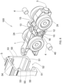
- the carriage is generally indicated with reference numeral 100.
- the carriage (100) comprises a body (1) shaped as a plate suitable for being disposed along a vertical plane.
- the body (1) of the carriage has a lower shank (12) that protrudes in lower position to receive connection means (not shown) for connecting the body (1) to a door panel (not shown).
- the connection means can be a vertical pin or a bolt that is fixed to a flange connected to an upper edge of the door panel.
- the lower shank (12) can be accessed through a hole (13) with upper counterbore.
- the hole (13) has a vertical axis, is opened on top and is centrally disposed in the body of the carriage.
- connection means consist in a vertical pin that rotates freely and is provided with an upper head that penetrates the counterbore of the hole (13).
- the body (1) has two through holes (10) with horizontal axis. Each through hole (10) defines a housing (11) wherein a rolling support (2) is mounted.
- the rolling support (2) can be a bearing that comprises an external ring (20) that is revolvingly mounted on an internal ring (21).
- a shaft (22) is mounted in the internal ring (20) of the bearing.
- the shaft (22) has two ends (23) that protrude laterally from the body (1) in order to be fixed in holes (25) of wheels (24).
- the shaft (22) can be fixed to the internal ring (20) or can be free to rotate inside the internal ring (20).
- the rolling support (2) can consist in a bush with a hole wherein the shaft (22) rotates freely.
- a stop ring (28) can be mounted in the housing (11) of the body to retain the rolling support (2). Obviously, the stop ring (28) can be replaced with other retention systems in order to retain the bearing.
- the rolling support (2) is a bearing
- the axial section of the internal ring (20) of the support has an external convex surface (26), which is shaped as an arc of circle and slides on a concave surface (27), which is shaped as an arc of circle, of the external ring of the bearing.
- the arc of circle of the concave surface (27) of the internal ring has the same radius of curvature as the arc of circle of the convex surface (26) of the external ring, and the arc of circle of the concave surface (27) of the internal ring is longer than the arc of circle of the convex surface (26) of the external ring.
- the shaft (22) has an axis (A) and a center of rotation (O) in a median point of the shaft, in such a way that the axis (A) of the shaft can be inclined in any direction relative to the center of rotation (O).
- Fig. 4 shows the situation wherein the axis (A) of the shaft (22) can be inclined relative to a horizontal axis by an angle of approximately +/- 10-15°, in such a way to adjust to the guiding rail wherein the carriage slides.
- the body (1) of the carriage has a front housing (14) suitable for removably receiving a front insert (3) that protrudes frontally from the body of the carriage.
- the front insert (3) is made of soft anti-noise material, and acts as buffer in order to stop against an end-of-travel stop disposed in the guiding rail of the carriage. In view of the above, the front insert (3) eliminates the noise caused when the carriage is stopped against the end-of-travel stop.
- the front housing (14) of the body of the carriage has a C-shaped longitudinal section.
- the front insert (3) has a cylindrical, parallelepiped or cubic shape or a tapered shape, such as a truncated conical or truncated pyramidal shape, with a rounded or flat head (30).
- the front insert (3) has a back collar (31) that protrudes outwards in order to be inserted and retained in the front housing (14) of the body.
- the body (1) of the carriage has two lateral housings (15) that protrude laterally from the body (1) in opposite directions.
- Each lateral housing (15) is disposed between two wheels (24).
- the lateral housings (15) consist in cylindrical shanks that protrude laterally from the body (1) in diametrically opposite directions relative to the axis of the hole (13) with vertical axis of the body of the carriage.
- Each lateral housing (15) has a cylindrical hole (16) suitable for removably receiving a lateral insert (4) that protrudes laterally from the body of the carriage.
- the lateral insert (4) has a cylindrical shape and a head (40) that can be rounded or flat. The head (40) of the lateral insert protrudes laterally from the body of the carriage, in a higher degree than the wheels (24).
- the lateral insert (4) or at least the head (40) of the lateral insert is made of a material with a low friction coefficient, such as a self-lubricating material like polytetrafluoroethylene (PTFE), which is known on the market with the Teflon trademark.
- PTFE polytetrafluoroethylene
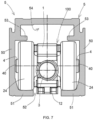
- Fig. 6 shows a guiding rail (5) suitable for being fixed to a secondary frame or to a wall or ceiling of a fixed structure.
- the guiding rail (5) consists in a section with a substantially C-shaped cross-section.
- the guiding rail (5) comprises two lateral walls (50) that continue with two separate lower walls (51) in such a way to define a lower longitudinal groove (52) that allows for the sliding movement of the connection means connected to the lower shank (12) of the body of the carriage.
- the wheels (24) of the carriage can roll on the lower walls (51) of the guiding rail.
- the guiding rail can comprise two longitudinal ribs (53) that extend inside the guiding rail in parallel direction to the lower walls (51) in such a way to define an upper housing (54) with a C-shape and a lower housing (55) wherein the carriage (100) slides.
- the wheels (24) of the carriage can roll on the lower walls (51) of the guiding rail and are disposed under the ribs (53) of the guiding rail.
- the heads (40) of the lateral inserts slide on the lateral walls (50) of the guiding rail in such a way to hold the carriage (100) in a perfectly centered position inside the guiding rail. In this way, the lateral inserts (4) can act as slides.
- the lateral inserts (4) are very useful when the carriage (100) is used in furnishings for boats because they reduce the lateral clearance between carriage and rail. In fact, the lateral inserts (4) prevent the carriage (100) from skidding in case of an anomalous lateral movement of the door panel (for example in rough sea conditions).
- the lateral inserts (4) can be extracted from their housings and replaced with inserts of different heights, according to the space that is left between the carriage and the lateral walls (50) of the guiding rail.
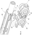
- the body (1) of the carriage has two lateral elements (17) that protrude laterally from the body (1) in opposite directions.
- the lateral elements (17) are disposed above the lateral housings (15) in diametrically opposite directions relative to the axis of the hole (13) with vertical axis of the body of the carriage.
- the lateral elements (17) of the body of the carriage are suitable for being fastened by a fastening system (60) provided in a first type of accessory (6) suitable for being connected to the carriage (100) and for sliding inside the guiding rail (5).
- the fastening system (60) comprises two U-shaped housings (61) suitable for fastening and retaining the lateral elements (17) of the body of the carriage.
- the first type of accessory (6) can be an accessory for the closing/return of the door panel when the door panel is opened or closed.
- the first type of accessory (6) comprises a section (62) suitable for sliding inside the upper housing (54) of the guiding rail.
- the section (62) supports an internally empty cylinder (63) with an axial hole (64) suitable for receiving a pin (M) made of magnetic material and fixed to the secondary frame, when the carriage (100) is approaching an end-of-travel position.
- the cylinder (63) is made of a conductive magnetic metal material. Therefore, when the pin (M) penetrates the hole (64) of the cylinder, a magnetic field is generated to return and retain the carriage (100).
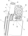
- the body (1) of the carriage has two back elements (18) that protrude at the back from the body (1) in such a way to define a U-shaped housing suitable for receiving a fastener (70) of a second type of accessory (7).
- the second type of accessory (7) is suitable for being connected to the carriage (100) and for sliding inside the guiding rail (5).
- the fastener (70) of the second type of accessory is shaped like a parallelepiped block and is disposed at a front end of the second type of accessory.
- the fastener (70) of the second type of accessory comprises a hole (71) with vertical axis.
- the back elements (18) of the body of the carriage comprise holes (18a) suitable for receiving screw or bolt means (B) that penetrate the hole (71) of the fastener (70) of the second type of accessory.
- the second type of accessory (7) comprises a section (72) with a height that is substantially equal to the height of the carriage (100) in order to slide inside the lower housing (55) of the sliding rail. Wheels (73) are mounted at a back end of the section (72) of the second type of accessory.
- a hook-slider (74) protrudes in upper position from the section (71) and slides in a longitudinal groove (75) of the section (71) that is open on top.
- the hook-slider (74) is fastened to an activator that is blocked in position in an upper portion of the guiding rail.
- the hook-slider (74) is connected to a return spring (79) disposed inside the section (71).
- Two guiding pins (76, 78) for each side are integral with the hook-slider (74) and slide in an L-shaped groove (77) obtained in the two lateral walls of the section (71).
- a coupling (8) is disposed between the back elements (18) of the body of the carriage and the fastener (70) of the second type of accessory (7).
- the coupling (8) comprises a hole (80) with vertical axis disposed in a parallelepiped block suitable for being disposed in the housing between the two back elements (18) of the body of the carriage.
- the hole (80) of the coupling is disposed in register with the holes (18a) of the back elements of the body of the carriage, in such a way that the screw or bolt means (B) penetrate the holes (18a, 80) of the back elements of the body of the carriage and of the coupling.
- the coupling (8) has two back elements (81) that define a U-shaped housing that receives the fastener (70) of the second type of accessory.
- the back elements (81) of the coupling are provided with holes (82) with horizontal axis.
- the fastener (70) of the second type of accessory is provided with holes (71) with horizontal axis.
- Screw or bolt means (B1) penetrate the holes (82) of the back elements of the coupling and the holes (71a) of the fastener of the second type of accessory in order to fasten the fastener of the second type of accessory to the coupling (8).
- the body (1) of the carriage is functional and simultaneously provides all the aforementioned different functions/features, namely:
Landscapes
- Engineering & Computer Science (AREA)
- Mechanical Engineering (AREA)
- Support Devices For Sliding Doors (AREA)
- Lock And Its Accessories (AREA)
- Power-Operated Mechanisms For Wings (AREA)
Description
- The present invention relates to a carriage and guiding rail assembly for sliding door panels, in particular for door panels suitable for being exposed to unbalancing forces in a direction that is not parallel to the sliding direction of the carriage, such as door panels installed on boats, means of transportation or door panels installed outdoor and therefore exposed to climatic actions, such as wind, and also door panels suitable for being installed in walls or ceilings that are not planar to the floor.
- As it is known, a sliding door is suitable for opening and closing an opening defined by a secondary frame in a fixed structure. A carriage is fixed to the door panel. The carriage slides in a guiding rail obtained with a section fixed to the secondary frame that defines the opening. Obviously, the secondary frame may be omitted.
- Generally, a clearance is provided between the body of the carriage and the guiding rail. Therefore, if the door panel is exposed to unbalancing forces in a direction that is not parallel to the sliding direction of the carriage, the carriage moves in the guiding rail in transverse direction, cannot slide and gets jammed, or the door panel might slide incorrectly, not being perpendicular to the floor.
- Moreover, it must be considered that various types of accessories must be connected to the carriage in order to slide inside the guiding rail. Such accessories may be used to ensure stability during the closing, the return and the deceleration of the door panel. However, the carriages of the prior art do not provide for connecting similar accessories, or in any case such a connection is difficult and complicated.
-
EP2586945 discloses a carriage for sliding doors according to the preamble ofclaim 1. - The purpose of the present invention is to eliminate the drawbacks of the prior art, by disclosing a carriage and guiding rail assembly for sliding doors that is efficient, reliable, practical, versatile and easy to make and install.
- These purposes are achieved according to the invention with the characteristics of the
independent claim 1. - Advantageous embodiments of the invention appear from the dependent claims.
- The carriage and guiding rail assembly for sliding door panels according to the invention is defined by
claim 1. - Additional features of the invention will be clearer from the following description, which refers to a merely illustrative, not limiting embodiment, as shown in the appended figures, wherein:
-
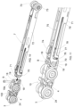
Fig. 1 is an exploded perspective view of the parts of a carriage of a carriage and guiding rail assembly according to the invention; -
Fig. 2 is the same view asFig. 1 , in cross-section along the axis of a pair of wheels of the carriage; -
Fig. 3 is a perspective cross-sectional view of the carriage ofFig. 2 in assembled condition; -
Fig. 4 is a cross-sectional view of the carriage along the axis of a pair of wheels, which shows an oscillating movement of the carriage; -
Fig. 5 is an exploded perspective view of the assembled carriage, which shows a front insert; -
Fig. 6 is an exploded perspective view of the assembled carriage, which shows two lateral inserts and a portion of guiding rail; -
Fig. 7 is a front cross-sectional view of the carriage disposed in the guiding rail; -
Fig. 8 is an exploded perspective view of the carriage, which shows a first type of accessory; -
Fig. 9 is a perspective view of the carriage with the first type of accessory disposed in the guiding rail; -
Fig. 10 is an exploded perspective view of the carriage, which shows a second type of accessory; -
Fig. 11 is a perspective view of the carriage and of the second type of accessory in assembled condition; -
Fig. 12 is an exploded perspective view of the carriage, which shows a coupling and the second type of accessory; and -
Fig. 13 is a perspective view of the carriage, of the coupling and of the second type of accessory in assembled condition. - With reference to the Figures, the carriage and guiding rail assembly according to the invention is described. The carriage is generally indicated with
reference numeral 100. - With reference to
Fig. 1 , the carriage (100) comprises a body (1) shaped as a plate suitable for being disposed along a vertical plane. The body (1) of the carriage has a lower shank (12) that protrudes in lower position to receive connection means (not shown) for connecting the body (1) to a door panel (not shown). For example, the connection means can be a vertical pin or a bolt that is fixed to a flange connected to an upper edge of the door panel. The lower shank (12) can be accessed through a hole (13) with upper counterbore. The hole (13) has a vertical axis, is opened on top and is centrally disposed in the body of the carriage. - For example, in case of folding door panels, the connection means consist in a vertical pin that rotates freely and is provided with an upper head that penetrates the counterbore of the hole (13).
- The body (1) has two through holes (10) with horizontal axis. Each through hole (10) defines a housing (11) wherein a rolling support (2) is mounted. The rolling support (2) can be a bearing that comprises an external ring (20) that is revolvingly mounted on an internal ring (21).
- A shaft (22) is mounted in the internal ring (20) of the bearing. The shaft (22) has two ends (23) that protrude laterally from the body (1) in order to be fixed in holes (25) of wheels (24). The shaft (22) can be fixed to the internal ring (20) or can be free to rotate inside the internal ring (20).
- Alternatively, the rolling support (2) can consist in a bush with a hole wherein the shaft (22) rotates freely.
- A stop ring (28) can be mounted in the housing (11) of the body to retain the rolling support (2). Obviously, the stop ring (28) can be replaced with other retention systems in order to retain the bearing.
- As shown in
Figs. 2- 4 , if the rolling support (2) is a bearing, the axial section of the internal ring (20) of the support has an external convex surface (26), which is shaped as an arc of circle and slides on a concave surface (27), which is shaped as an arc of circle, of the external ring of the bearing. The arc of circle of the concave surface (27) of the internal ring has the same radius of curvature as the arc of circle of the convex surface (26) of the external ring, and the arc of circle of the concave surface (27) of the internal ring is longer than the arc of circle of the convex surface (26) of the external ring. - With reference to
Fig. 4 , the shaft (22) has an axis (A) and a center of rotation (O) in a median point of the shaft, in such a way that the axis (A) of the shaft can be inclined in any direction relative to the center of rotation (O). - The arc of circle of the concave surface (27) of the internal ring and the arc of circle of the convex surface (26) of the external ring have a center of curvature that coincides with the center of rotation (O). Therefore, the shaft (22) disposed in the internal ring (20) of the bearing can oscillate around its center of rotation (O) in any direction, also following the curvilinear trajectory of the guiding rail.
Fig. 4 shows the situation wherein the axis (A) of the shaft (22) can be inclined relative to a horizontal axis by an angle of approximately +/- 10-15°, in such a way to adjust to the guiding rail wherein the carriage slides. - With reference to
Fig. 5 , the body (1) of the carriage has a front housing (14) suitable for removably receiving a front insert (3) that protrudes frontally from the body of the carriage. The front insert (3) is made of soft anti-noise material, and acts as buffer in order to stop against an end-of-travel stop disposed in the guiding rail of the carriage. In view of the above, the front insert (3) eliminates the noise caused when the carriage is stopped against the end-of-travel stop. - The front housing (14) of the body of the carriage has a C-shaped longitudinal section. The front insert (3) has a cylindrical, parallelepiped or cubic shape or a tapered shape, such as a truncated conical or truncated pyramidal shape, with a rounded or flat head (30). The front insert (3) has a back collar (31) that protrudes outwards in order to be inserted and retained in the front housing (14) of the body.
- With reference to
Fig. 6 , the body (1) of the carriage has two lateral housings (15) that protrude laterally from the body (1) in opposite directions. Each lateral housing (15) is disposed between two wheels (24). The lateral housings (15) consist in cylindrical shanks that protrude laterally from the body (1) in diametrically opposite directions relative to the axis of the hole (13) with vertical axis of the body of the carriage. - Each lateral housing (15) has a cylindrical hole (16) suitable for removably receiving a lateral insert (4) that protrudes laterally from the body of the carriage. The lateral insert (4) has a cylindrical shape and a head (40) that can be rounded or flat. The head (40) of the lateral insert protrudes laterally from the body of the carriage, in a higher degree than the wheels (24).
- The lateral insert (4) or at least the head (40) of the lateral insert is made of a material with a low friction coefficient, such as a self-lubricating material like polytetrafluoroethylene (PTFE), which is known on the market with the Teflon trademark.
-
Fig. 6 shows a guiding rail (5) suitable for being fixed to a secondary frame or to a wall or ceiling of a fixed structure. The guiding rail (5) consists in a section with a substantially C-shaped cross-section. The guiding rail (5) comprises two lateral walls (50) that continue with two separate lower walls (51) in such a way to define a lower longitudinal groove (52) that allows for the sliding movement of the connection means connected to the lower shank (12) of the body of the carriage. - The wheels (24) of the carriage can roll on the lower walls (51) of the guiding rail.
- The guiding rail can comprise two longitudinal ribs (53) that extend inside the guiding rail in parallel direction to the lower walls (51) in such a way to define an upper housing (54) with a C-shape and a lower housing (55) wherein the carriage (100) slides.
- With reference to
Fig. 7 , when the carriage (100) is disposed in the guiding rail (5), the wheels (24) of the carriage can roll on the lower walls (51) of the guiding rail and are disposed under the ribs (53) of the guiding rail. The heads (40) of the lateral inserts slide on the lateral walls (50) of the guiding rail in such a way to hold the carriage (100) in a perfectly centered position inside the guiding rail. In this way, the lateral inserts (4) can act as slides. - The lateral inserts (4) are very useful when the carriage (100) is used in furnishings for boats because they reduce the lateral clearance between carriage and rail. In fact, the lateral inserts (4) prevent the carriage (100) from skidding in case of an anomalous lateral movement of the door panel (for example in rough sea conditions).
- Moreover, the lateral inserts (4) can be extracted from their housings and replaced with inserts of different heights, according to the space that is left between the carriage and the lateral walls (50) of the guiding rail.
- With reference to
Figs. 8 and9 , the body (1) of the carriage has two lateral elements (17) that protrude laterally from the body (1) in opposite directions. The lateral elements (17) are disposed above the lateral housings (15) in diametrically opposite directions relative to the axis of the hole (13) with vertical axis of the body of the carriage. - The lateral elements (17) of the body of the carriage are suitable for being fastened by a fastening system (60) provided in a first type of accessory (6) suitable for being connected to the carriage (100) and for sliding inside the guiding rail (5). The fastening system (60) comprises two U-shaped housings (61) suitable for fastening and retaining the lateral elements (17) of the body of the carriage.
- The first type of accessory (6) can be an accessory for the closing/return of the door panel when the door panel is opened or closed. The first type of accessory (6) comprises a section (62) suitable for sliding inside the upper housing (54) of the guiding rail. The section (62) supports an internally empty cylinder (63) with an axial hole (64) suitable for receiving a pin (M) made of magnetic material and fixed to the secondary frame, when the carriage (100) is approaching an end-of-travel position. The cylinder (63) is made of a conductive magnetic metal material. Therefore, when the pin (M) penetrates the hole (64) of the cylinder, a magnetic field is generated to return and retain the carriage (100).
- With reference to
Figs. 10 and 11 , the body (1) of the carriage has two back elements (18) that protrude at the back from the body (1) in such a way to define a U-shaped housing suitable for receiving a fastener (70) of a second type of accessory (7). The second type of accessory (7) is suitable for being connected to the carriage (100) and for sliding inside the guiding rail (5). - The fastener (70) of the second type of accessory is shaped like a parallelepiped block and is disposed at a front end of the second type of accessory. The fastener (70) of the second type of accessory comprises a hole (71) with vertical axis. The back elements (18) of the body of the carriage comprise holes (18a) suitable for receiving screw or bolt means (B) that penetrate the hole (71) of the fastener (70) of the second type of accessory.
- The second type of accessory (7) comprises a section (72) with a height that is substantially equal to the height of the carriage (100) in order to slide inside the lower housing (55) of the sliding rail. Wheels (73) are mounted at a back end of the section (72) of the second type of accessory.
- A hook-slider (74) protrudes in upper position from the section (71) and slides in a longitudinal groove (75) of the section (71) that is open on top. The hook-slider (74) is fastened to an activator that is blocked in position in an upper portion of the guiding rail.
- The hook-slider (74) is connected to a return spring (79) disposed inside the section (71). Two guiding pins (76, 78) for each side are integral with the hook-slider (74) and slide in an L-shaped groove (77) obtained in the two lateral walls of the section (71).
- With reference to
Figs. 12 and 13 , a coupling (8) is disposed between the back elements (18) of the body of the carriage and the fastener (70) of the second type of accessory (7). - The coupling (8) comprises a hole (80) with vertical axis disposed in a parallelepiped block suitable for being disposed in the housing between the two back elements (18) of the body of the carriage. The hole (80) of the coupling is disposed in register with the holes (18a) of the back elements of the body of the carriage, in such a way that the screw or bolt means (B) penetrate the holes (18a, 80) of the back elements of the body of the carriage and of the coupling.
- The coupling (8) has two back elements (81) that define a U-shaped housing that receives the fastener (70) of the second type of accessory. The back elements (81) of the coupling are provided with holes (82) with horizontal axis. The fastener (70) of the second type of accessory is provided with holes (71) with horizontal axis. Screw or bolt means (B1) penetrate the holes (82) of the back elements of the coupling and the holes (71a) of the fastener of the second type of accessory in order to fasten the fastener of the second type of accessory to the coupling (8).
- This description continues with an illustration of the features and functions of the carriage (100) according to the invention. The body (1) of the carriage is functional and simultaneously provides all the aforementioned different functions/features, namely:
- the possibility to add lateral inserts (4) that act as stability slides;
- the possibility to adjust to the guiding rail (5) by means of the supports (2) that consist in special bearings that permit to incline the axis (A) of the shaft (22) in any direction relative to the center (O) of the shaft (22). The bearings permit to use the carriage (100) also in a curved guiding rail.
- the possibility to add a front insert (3) that acts as a bumper;
- the possibility to connect the door panel (specifically, a folding door panel) by means of a pin with an upper head because of the provision of the through hole (13) in the body with upper counterbore (13) that receives the head of the pin;
- the possibility to draw an accessory, such as an accessory (6) for returning/closing the door panel, by means of the lateral elements (17) of the body of the carriage; and
- the possibility to connect an accessory, such as an accessory (7) for returning/closing the door panel, by means of the back elements (18).
Claims (10)
- Carriage (100) and guiding rail (5) assembly for sliding doors, wherein the guiding rail (5) comprises a profile with a C-shaped cross-section having lateral walls (50), said carriage (100) comprising:- a body (1) shaped as a plate suitable for being disposed along a vertical plane,- a lower shank (12) that protrudes in lower position from the body to receive connection means for connecting the body (1) of the carriage to a door panel, and- wheels (24) revolvingly connected to the body (1) of the carriage and suitable for rolling inside said guiding rail (5),said carriage (100) further comprises:- lateral inserts (4) that are removably inserted in lateral housings (15) obtained on the sides of the body of the carriage, in such a way to protrude laterally in opposite directions from the body of the carriage in order to slide on said lateral walls (50) of said guiding rail; wherein each lateral insert (4) is at least partially made of a material with a low friction coefficient compared to the lateral walls (50) of the guiding rail; each lateral insert (4) having a head (40) protruding laterally from the body of the carriage, in a higher degree than the wheels (24);characterized in thatthe heads (40) of the lateral inserts (4) slide on the lateral walls (50) of the guiding rail acting as slides, in such a way to hold the carriage (100) in a perfectly centered position inside the guiding rail.
- The carriage (100) and guiding rail (5) assembly of claim 1, wherein said lateral housings (15) obtained on the sides of the body of the carriage comprise cylindrical shanks that protrude laterally in opposite directions from the body of the carriage.
- The carriage (100) and guiding rail (5) assembly of claim 1 or 2, wherein each lateral insert (4) has a cylindrical shape and the head (40) can be rounded or flat.
- The carriage (100) and guiding rail (5) assembly of any one of the preceding claims, wherein said lateral insert (4) is at least partially made of self-lubricating material, such as polytetrafluoroethylene (PTFE).
- The carriage (100) and guiding rail (5) assembly of any one of the preceding claims, also comprising a front insert (3) that is removably mounted in a front housing (14) of the body of the carriage, wherein said front insert (3) is made of soft anti-noise material and acts as buffer in order to stop against an end-of-travel stop disposed in the guiding rail (5).
- The carriage (100) and guiding rail (5) assembly of claim 5, wherein said front housing (14) of the body of the carriage has a C-shaped longitudinal section and said front insert (3) has a cylindrical, parallelepiped, cubic or tapered truncated-conical or truncated-pyramidal shape and comprises a rounded or flat head (30) and a back collar (31) that protrudes outwards in order to be inserted and retained in the front housing (14) of the body of the carriage.
- The carriage (100) and guiding rail (5) assembly of any one of the preceding claims, wherein the body (1) of the carriage has two lateral elements (17) that protrude laterally from the body of the carriage in opposite directions; said lateral elements (17) of the body of the carriage being suitable for being fastened by a fastening system (60) provided in a first type of accessory (6) suitable for being connected to the carriage (100) and for sliding inside the guiding rail (5).
- The carriage (100) and guiding rail (5) assembly of any one of the preceding claims, wherein the body (1) of the carriage has two back elements (18) that protrude at the back from the body of the carriage in such a way to define a U-shaped housing suitable for receiving a fastener (70) provided in a second type of accessory (7) suitable for being connected to the carriage (100) and for sliding inside the guiding rail (5).
- The carriage (100) and guiding rail (5) assembly of any one of claims 1 to 7, wherein the body (1) of the carriage has two back elements (18) that protrude at the back from the body of the carriage in such a way to define a U-shaped housing suitable for receiving a coupling (8) that is connected with a fastener (70) provided in a second type of accessory (7) suitable for being connected to the carriage (100) and for sliding inside the guiding rail (5).
- The carriage (100) and guiding rail (5) assembly of any one of the preceding claims, also comprising two supports (2) mounted in housings (11) of the body of the carriage; each support (2) being a bearing that comprises an external ring (20) revolvingly mounted on an internal ring (21); the external ring (21) being fixed in the housing (11) of the body of the carriage and the shaft (22) being inserted in the internal ring (20) of the bearing; the shaft (22) being provided with two ends (23) that protrude laterally from the body (1) in order to be fixed to the wheels (24); wherein the axial section of the internal ring (20) of the bearing has an external convex surface (26), which is shaped as an arc of circle and slides on a concave surface (27) shaped as an arc of circle of the external ring of the bearing.
Applications Claiming Priority (1)
| Application Number | Priority Date | Filing Date | Title |
|---|---|---|---|
| IT102019000006579A IT201900006579A1 (en) | 2019-05-06 | 2019-05-06 | CARRIAGE FOR SLIDING DOORS |
Publications (3)
| Publication Number | Publication Date |
|---|---|
| EP3736401A1 EP3736401A1 (en) | 2020-11-11 |
| EP3736401B1 EP3736401B1 (en) | 2022-03-30 |
| EP3736401B2 true EP3736401B2 (en) | 2025-05-07 |
Family
ID=67513663
Family Applications (1)
| Application Number | Title | Priority Date | Filing Date |
|---|---|---|---|
| EP20173031.4A Active EP3736401B2 (en) | 2019-05-06 | 2020-05-05 | Carriage and guiding rail assembly for sliding door panels |
Country Status (3)
| Country | Link |
|---|---|
| EP (1) | EP3736401B2 (en) |
| ES (1) | ES2921431T3 (en) |
| IT (1) | IT201900006579A1 (en) |
Families Citing this family (1)
| Publication number | Priority date | Publication date | Assignee | Title |
|---|---|---|---|---|
| DE102023210534A1 (en) * | 2023-10-25 | 2025-04-30 | Aug. Winkhaus SE & Co. KG | Carriage for moving a window sash |
Citations (5)
| Publication number | Priority date | Publication date | Assignee | Title |
|---|---|---|---|---|
| US3193870A (en) † | 1963-04-25 | 1965-07-13 | Lawrence Brothers | Truck assembly for sliding doors |
| WO2007075075A1 (en) † | 2005-12-29 | 2007-07-05 | Kwang-Seok Lee | Method and apparatus for window closing in the sliding window system |
| WO2010019692A1 (en) † | 2008-08-14 | 2010-02-18 | Hettich-Heinze Gmbh & Co. Kg | Carriage for a door |
| EP2636834A1 (en) † | 2012-03-07 | 2013-09-11 | Sliding S.R.L. | Trolley assembly for support and movement of sliding panels of furniture or doors |
| US20150047150A1 (en) † | 2012-03-30 | 2015-02-19 | Nifco Inc. | Movable body assistance device |
Family Cites Families (2)
| Publication number | Priority date | Publication date | Assignee | Title |
|---|---|---|---|---|
| WO2008044252A1 (en) * | 2006-10-10 | 2008-04-17 | Luigi Maifredi | Door moving system with rotation and translation and method for mounting such a system |
| ITTV20110149A1 (en) * | 2011-10-31 | 2013-05-01 | Eclisse Srl | CART STRUCTURE |
-
2019
- 2019-05-06 IT IT102019000006579A patent/IT201900006579A1/en unknown
-
2020
- 2020-05-05 EP EP20173031.4A patent/EP3736401B2/en active Active
- 2020-05-05 ES ES20173031T patent/ES2921431T3/en active Active
Patent Citations (5)
| Publication number | Priority date | Publication date | Assignee | Title |
|---|---|---|---|---|
| US3193870A (en) † | 1963-04-25 | 1965-07-13 | Lawrence Brothers | Truck assembly for sliding doors |
| WO2007075075A1 (en) † | 2005-12-29 | 2007-07-05 | Kwang-Seok Lee | Method and apparatus for window closing in the sliding window system |
| WO2010019692A1 (en) † | 2008-08-14 | 2010-02-18 | Hettich-Heinze Gmbh & Co. Kg | Carriage for a door |
| EP2636834A1 (en) † | 2012-03-07 | 2013-09-11 | Sliding S.R.L. | Trolley assembly for support and movement of sliding panels of furniture or doors |
| US20150047150A1 (en) † | 2012-03-30 | 2015-02-19 | Nifco Inc. | Movable body assistance device |
Also Published As
| Publication number | Publication date |
|---|---|
| EP3736401B1 (en) | 2022-03-30 |
| IT201900006579A1 (en) | 2020-11-06 |
| EP3736401A1 (en) | 2020-11-11 |
| ES2921431T3 (en) | 2022-08-25 |
Similar Documents
| Publication | Publication Date | Title |
|---|---|---|
| US5075928A (en) | Concealed architectural hinge assembly | |
| CA2377526C (en) | Segmented garage door and hinges | |
| US20090102332A1 (en) | Cabinet door locking mechanism | |
| US6550838B2 (en) | Cargo box tailgate assembly | |
| US9856685B1 (en) | Garage door hinge with noise reduction insert | |
| EP3736401B2 (en) | Carriage and guiding rail assembly for sliding door panels | |
| AU2011301131B2 (en) | Guide assembly | |
| US4439888A (en) | Substantially concealed hinge for door with recess | |
| US20030200628A1 (en) | Continuous door hinge with multi-plastic bearings | |
| US3342246A (en) | Guide assembly for bifolding doors | |
| EP1060319B1 (en) | Arrangement for pivotable and slidable suspension of sheets | |
| US20120297686A1 (en) | Door support for glass sliding door and assembly | |
| US5452543A (en) | Window operator track with integral limit stop | |
| CN214403137U (en) | Pre-assembled hinge module and hinge system | |
| US5031274A (en) | Floor door lock | |
| US7721387B1 (en) | Track assembly for an overhead door | |
| EP2636834A1 (en) | Trolley assembly for support and movement of sliding panels of furniture or doors | |
| US20040211033A1 (en) | Track assembly for an overhead door | |
| US11060335B2 (en) | Rod securing hinge and method | |
| US3216054A (en) | Hinge arrangement for pivotal closures | |
| US3874027A (en) | Shock absorbing bearing assembly | |
| CN201447981U (en) | Limiting hinge | |
| US20090081012A1 (en) | System and Method for Securing Lift Gate | |
| IL42653A (en) | A hinge for cabinet doors and the like | |
| US20210310302A1 (en) | Universal endlock |
Legal Events
| Date | Code | Title | Description |
|---|---|---|---|
| PUAI | Public reference made under article 153(3) epc to a published international application that has entered the european phase |
Free format text: ORIGINAL CODE: 0009012 |
|
| STAA | Information on the status of an ep patent application or granted ep patent |
Free format text: STATUS: THE APPLICATION HAS BEEN PUBLISHED |
|
| AK | Designated contracting states |
Kind code of ref document: A1 Designated state(s): AL AT BE BG CH CY CZ DE DK EE ES FI FR GB GR HR HU IE IS IT LI LT LU LV MC MK MT NL NO PL PT RO RS SE SI SK SM TR |
|
| AX | Request for extension of the european patent |
Extension state: BA ME |
|
| STAA | Information on the status of an ep patent application or granted ep patent |
Free format text: STATUS: REQUEST FOR EXAMINATION WAS MADE |
|
| 17P | Request for examination filed |
Effective date: 20210505 |
|
| RBV | Designated contracting states (corrected) |
Designated state(s): AL AT BE BG CH CY CZ DE DK EE ES FI FR GB GR HR HU IE IS IT LI LT LU LV MC MK MT NL NO PL PT RO RS SE SI SK SM TR |
|
| GRAP | Despatch of communication of intention to grant a patent |
Free format text: ORIGINAL CODE: EPIDOSNIGR1 |
|
| STAA | Information on the status of an ep patent application or granted ep patent |
Free format text: STATUS: GRANT OF PATENT IS INTENDED |
|
| INTG | Intention to grant announced |
Effective date: 20211025 |
|
| RIN1 | Information on inventor provided before grant (corrected) |
Inventor name: BIANCHINI, LUCA Inventor name: PAGLIAROLI, GERARDO |
|
| GRAS | Grant fee paid |
Free format text: ORIGINAL CODE: EPIDOSNIGR3 |
|
| GRAA | (expected) grant |
Free format text: ORIGINAL CODE: 0009210 |
|
| STAA | Information on the status of an ep patent application or granted ep patent |
Free format text: STATUS: THE PATENT HAS BEEN GRANTED |
|
| AK | Designated contracting states |
Kind code of ref document: B1 Designated state(s): AL AT BE BG CH CY CZ DE DK EE ES FI FR GB GR HR HU IE IS IT LI LT LU LV MC MK MT NL NO PL PT RO RS SE SI SK SM TR |
|
| REG | Reference to a national code |
Ref country code: GB Ref legal event code: FG4D |
|
| REG | Reference to a national code |
Ref country code: CH Ref legal event code: EP |
|
| REG | Reference to a national code |
Ref country code: AT Ref legal event code: REF Ref document number: 1479333 Country of ref document: AT Kind code of ref document: T Effective date: 20220415 |
|
| REG | Reference to a national code |
Ref country code: DE Ref legal event code: R096 Ref document number: 602020002394 Country of ref document: DE |
|
| REG | Reference to a national code |
Ref country code: IE Ref legal event code: FG4D |
|
| REG | Reference to a national code |
Ref country code: LT Ref legal event code: MG9D |
|
| PG25 | Lapsed in a contracting state [announced via postgrant information from national office to epo] |
Ref country code: SE Free format text: LAPSE BECAUSE OF FAILURE TO SUBMIT A TRANSLATION OF THE DESCRIPTION OR TO PAY THE FEE WITHIN THE PRESCRIBED TIME-LIMIT Effective date: 20220330 Ref country code: RS Free format text: LAPSE BECAUSE OF FAILURE TO SUBMIT A TRANSLATION OF THE DESCRIPTION OR TO PAY THE FEE WITHIN THE PRESCRIBED TIME-LIMIT Effective date: 20220330 Ref country code: NO Free format text: LAPSE BECAUSE OF FAILURE TO SUBMIT A TRANSLATION OF THE DESCRIPTION OR TO PAY THE FEE WITHIN THE PRESCRIBED TIME-LIMIT Effective date: 20220630 Ref country code: LT Free format text: LAPSE BECAUSE OF FAILURE TO SUBMIT A TRANSLATION OF THE DESCRIPTION OR TO PAY THE FEE WITHIN THE PRESCRIBED TIME-LIMIT Effective date: 20220330 Ref country code: HR Free format text: LAPSE BECAUSE OF FAILURE TO SUBMIT A TRANSLATION OF THE DESCRIPTION OR TO PAY THE FEE WITHIN THE PRESCRIBED TIME-LIMIT Effective date: 20220330 Ref country code: BG Free format text: LAPSE BECAUSE OF FAILURE TO SUBMIT A TRANSLATION OF THE DESCRIPTION OR TO PAY THE FEE WITHIN THE PRESCRIBED TIME-LIMIT Effective date: 20220630 |
|
| REG | Reference to a national code |
Ref country code: NL Ref legal event code: MP Effective date: 20220330 |
|
| REG | Reference to a national code |
Ref country code: AT Ref legal event code: MK05 Ref document number: 1479333 Country of ref document: AT Kind code of ref document: T Effective date: 20220330 |
|
| REG | Reference to a national code |
Ref country code: ES Ref legal event code: FG2A Ref document number: 2921431 Country of ref document: ES Kind code of ref document: T3 Effective date: 20220825 |
|
| PG25 | Lapsed in a contracting state [announced via postgrant information from national office to epo] |
Ref country code: LV Free format text: LAPSE BECAUSE OF FAILURE TO SUBMIT A TRANSLATION OF THE DESCRIPTION OR TO PAY THE FEE WITHIN THE PRESCRIBED TIME-LIMIT Effective date: 20220330 Ref country code: GR Free format text: LAPSE BECAUSE OF FAILURE TO SUBMIT A TRANSLATION OF THE DESCRIPTION OR TO PAY THE FEE WITHIN THE PRESCRIBED TIME-LIMIT Effective date: 20220701 Ref country code: FI Free format text: LAPSE BECAUSE OF FAILURE TO SUBMIT A TRANSLATION OF THE DESCRIPTION OR TO PAY THE FEE WITHIN THE PRESCRIBED TIME-LIMIT Effective date: 20220330 |
|
| PG25 | Lapsed in a contracting state [announced via postgrant information from national office to epo] |
Ref country code: NL Free format text: LAPSE BECAUSE OF FAILURE TO SUBMIT A TRANSLATION OF THE DESCRIPTION OR TO PAY THE FEE WITHIN THE PRESCRIBED TIME-LIMIT Effective date: 20220330 |
|
| PG25 | Lapsed in a contracting state [announced via postgrant information from national office to epo] |
Ref country code: SM Free format text: LAPSE BECAUSE OF FAILURE TO SUBMIT A TRANSLATION OF THE DESCRIPTION OR TO PAY THE FEE WITHIN THE PRESCRIBED TIME-LIMIT Effective date: 20220330 Ref country code: SK Free format text: LAPSE BECAUSE OF FAILURE TO SUBMIT A TRANSLATION OF THE DESCRIPTION OR TO PAY THE FEE WITHIN THE PRESCRIBED TIME-LIMIT Effective date: 20220330 Ref country code: RO Free format text: LAPSE BECAUSE OF FAILURE TO SUBMIT A TRANSLATION OF THE DESCRIPTION OR TO PAY THE FEE WITHIN THE PRESCRIBED TIME-LIMIT Effective date: 20220330 Ref country code: PT Free format text: LAPSE BECAUSE OF FAILURE TO SUBMIT A TRANSLATION OF THE DESCRIPTION OR TO PAY THE FEE WITHIN THE PRESCRIBED TIME-LIMIT Effective date: 20220801 Ref country code: EE Free format text: LAPSE BECAUSE OF FAILURE TO SUBMIT A TRANSLATION OF THE DESCRIPTION OR TO PAY THE FEE WITHIN THE PRESCRIBED TIME-LIMIT Effective date: 20220330 Ref country code: CZ Free format text: LAPSE BECAUSE OF FAILURE TO SUBMIT A TRANSLATION OF THE DESCRIPTION OR TO PAY THE FEE WITHIN THE PRESCRIBED TIME-LIMIT Effective date: 20220330 Ref country code: AT Free format text: LAPSE BECAUSE OF FAILURE TO SUBMIT A TRANSLATION OF THE DESCRIPTION OR TO PAY THE FEE WITHIN THE PRESCRIBED TIME-LIMIT Effective date: 20220330 |
|
| REG | Reference to a national code |
Ref country code: DE Ref legal event code: R026 Ref document number: 602020002394 Country of ref document: DE |
|
| PLBI | Opposition filed |
Free format text: ORIGINAL CODE: 0009260 |
|
| PLAB | Opposition data, opponent's data or that of the opponent's representative modified |
Free format text: ORIGINAL CODE: 0009299OPPO |
|
| PG25 | Lapsed in a contracting state [announced via postgrant information from national office to epo] |
Ref country code: PL Free format text: LAPSE BECAUSE OF FAILURE TO SUBMIT A TRANSLATION OF THE DESCRIPTION OR TO PAY THE FEE WITHIN THE PRESCRIBED TIME-LIMIT Effective date: 20220330 Ref country code: IS Free format text: LAPSE BECAUSE OF FAILURE TO SUBMIT A TRANSLATION OF THE DESCRIPTION OR TO PAY THE FEE WITHIN THE PRESCRIBED TIME-LIMIT Effective date: 20220730 Ref country code: AL Free format text: LAPSE BECAUSE OF FAILURE TO SUBMIT A TRANSLATION OF THE DESCRIPTION OR TO PAY THE FEE WITHIN THE PRESCRIBED TIME-LIMIT Effective date: 20220330 |
|
| 26 | Opposition filed |
Opponent name: GEZE GMBH Effective date: 20221117 |
|
| R26 | Opposition filed (corrected) |
Opponent name: GEZE GMBH Effective date: 20221117 |
|
| PLAX | Notice of opposition and request to file observation + time limit sent |
Free format text: ORIGINAL CODE: EPIDOSNOBS2 |
|
| REG | Reference to a national code |
Ref country code: BE Ref legal event code: MM Effective date: 20220531 |
|
| PG25 | Lapsed in a contracting state [announced via postgrant information from national office to epo] |
Ref country code: MC Free format text: LAPSE BECAUSE OF FAILURE TO SUBMIT A TRANSLATION OF THE DESCRIPTION OR TO PAY THE FEE WITHIN THE PRESCRIBED TIME-LIMIT Effective date: 20220330 Ref country code: DK Free format text: LAPSE BECAUSE OF FAILURE TO SUBMIT A TRANSLATION OF THE DESCRIPTION OR TO PAY THE FEE WITHIN THE PRESCRIBED TIME-LIMIT Effective date: 20220330 Ref country code: LU Free format text: LAPSE BECAUSE OF NON-PAYMENT OF DUE FEES Effective date: 20220505 |
|
| PG25 | Lapsed in a contracting state [announced via postgrant information from national office to epo] |
Ref country code: IE Free format text: LAPSE BECAUSE OF NON-PAYMENT OF DUE FEES Effective date: 20220505 |
|
| PLBB | Reply of patent proprietor to notice(s) of opposition received |
Free format text: ORIGINAL CODE: EPIDOSNOBS3 |
|
| PG25 | Lapsed in a contracting state [announced via postgrant information from national office to epo] |
Ref country code: SI Free format text: LAPSE BECAUSE OF FAILURE TO SUBMIT A TRANSLATION OF THE DESCRIPTION OR TO PAY THE FEE WITHIN THE PRESCRIBED TIME-LIMIT Effective date: 20220330 Ref country code: BE Free format text: LAPSE BECAUSE OF NON-PAYMENT OF DUE FEES Effective date: 20220531 |
|
| PLBP | Opposition withdrawn |
Free format text: ORIGINAL CODE: 0009264 |
|
| PLAY | Examination report in opposition despatched + time limit |
Free format text: ORIGINAL CODE: EPIDOSNORE2 |
|
| PG25 | Lapsed in a contracting state [announced via postgrant information from national office to epo] |
Ref country code: MK Free format text: LAPSE BECAUSE OF FAILURE TO SUBMIT A TRANSLATION OF THE DESCRIPTION OR TO PAY THE FEE WITHIN THE PRESCRIBED TIME-LIMIT Effective date: 20220330 Ref country code: CY Free format text: LAPSE BECAUSE OF FAILURE TO SUBMIT A TRANSLATION OF THE DESCRIPTION OR TO PAY THE FEE WITHIN THE PRESCRIBED TIME-LIMIT Effective date: 20220330 |
|
| PG25 | Lapsed in a contracting state [announced via postgrant information from national office to epo] |
Ref country code: HU Free format text: LAPSE BECAUSE OF FAILURE TO SUBMIT A TRANSLATION OF THE DESCRIPTION OR TO PAY THE FEE WITHIN THE PRESCRIBED TIME-LIMIT; INVALID AB INITIO Effective date: 20200505 |
|
| PG25 | Lapsed in a contracting state [announced via postgrant information from national office to epo] |
Ref country code: TR Free format text: LAPSE BECAUSE OF FAILURE TO SUBMIT A TRANSLATION OF THE DESCRIPTION OR TO PAY THE FEE WITHIN THE PRESCRIBED TIME-LIMIT Effective date: 20220330 |
|
| PLBC | Reply to examination report in opposition received |
Free format text: ORIGINAL CODE: EPIDOSNORE3 |
|
| PG25 | Lapsed in a contracting state [announced via postgrant information from national office to epo] |
Ref country code: MT Free format text: LAPSE BECAUSE OF FAILURE TO SUBMIT A TRANSLATION OF THE DESCRIPTION OR TO PAY THE FEE WITHIN THE PRESCRIBED TIME-LIMIT Effective date: 20220330 |
|
| GBPC | Gb: european patent ceased through non-payment of renewal fee |
Effective date: 20240505 |
|
| PUAH | Patent maintained in amended form |
Free format text: ORIGINAL CODE: 0009272 |
|
| STAA | Information on the status of an ep patent application or granted ep patent |
Free format text: STATUS: PATENT MAINTAINED AS AMENDED |
|
| PG25 | Lapsed in a contracting state [announced via postgrant information from national office to epo] |
Ref country code: GB Free format text: LAPSE BECAUSE OF NON-PAYMENT OF DUE FEES Effective date: 20240505 |
|
| 27A | Patent maintained in amended form |
Effective date: 20250507 |
|
| AK | Designated contracting states |
Kind code of ref document: B2 Designated state(s): AL AT BE BG CH CY CZ DE DK EE ES FI FR GB GR HR HU IE IS IT LI LT LU LV MC MK MT NL NO PL PT RO RS SE SI SK SM TR |
|
| REG | Reference to a national code |
Ref country code: DE Ref legal event code: R102 Ref document number: 602020002394 Country of ref document: DE |
|
| PGFP | Annual fee paid to national office [announced via postgrant information from national office to epo] |
Ref country code: DE Payment date: 20250528 Year of fee payment: 6 |
|
| PGFP | Annual fee paid to national office [announced via postgrant information from national office to epo] |
Ref country code: ES Payment date: 20250612 Year of fee payment: 6 |
|
| PGFP | Annual fee paid to national office [announced via postgrant information from national office to epo] |
Ref country code: IT Payment date: 20250417 Year of fee payment: 6 |
|
| PGFP | Annual fee paid to national office [announced via postgrant information from national office to epo] |
Ref country code: FR Payment date: 20250526 Year of fee payment: 6 |
|
| PGFP | Annual fee paid to national office [announced via postgrant information from national office to epo] |
Ref country code: CH Payment date: 20250601 Year of fee payment: 6 |
|
| PG25 | Lapsed in a contracting state [announced via postgrant information from national office to epo] |
Ref country code: ES Free format text: LAPSE BECAUSE OF FAILURE TO SUBMIT A TRANSLATION OF THE DESCRIPTION OR TO PAY THE FEE WITHIN THE PRESCRIBED TIME-LIMIT Effective date: 20250507 |