EP3736255A1 - Method for producing carbide ceramic fibre composite and carbide ceramic component - Google Patents
Method for producing carbide ceramic fibre composite and carbide ceramic component Download PDFInfo
- Publication number
- EP3736255A1 EP3736255A1 EP20172147.9A EP20172147A EP3736255A1 EP 3736255 A1 EP3736255 A1 EP 3736255A1 EP 20172147 A EP20172147 A EP 20172147A EP 3736255 A1 EP3736255 A1 EP 3736255A1
- Authority
- EP
- European Patent Office
- Prior art keywords
- fiber
- carbide
- fibers
- porous
- solvent
- Prior art date
- Legal status (The legal status is an assumption and is not a legal conclusion. Google has not performed a legal analysis and makes no representation as to the accuracy of the status listed.)
- Pending
Links
Images


Classifications
-
- C—CHEMISTRY; METALLURGY
- C04—CEMENTS; CONCRETE; ARTIFICIAL STONE; CERAMICS; REFRACTORIES
- C04B—LIME, MAGNESIA; SLAG; CEMENTS; COMPOSITIONS THEREOF, e.g. MORTARS, CONCRETE OR LIKE BUILDING MATERIALS; ARTIFICIAL STONE; CERAMICS; REFRACTORIES; TREATMENT OF NATURAL STONE
- C04B35/00—Shaped ceramic products characterised by their composition; Ceramics compositions; Processing powders of inorganic compounds preparatory to the manufacturing of ceramic products
- C04B35/71—Ceramic products containing macroscopic reinforcing agents
- C04B35/78—Ceramic products containing macroscopic reinforcing agents containing non-metallic materials
- C04B35/80—Fibres, filaments, whiskers, platelets, or the like
-
- C—CHEMISTRY; METALLURGY
- C04—CEMENTS; CONCRETE; ARTIFICIAL STONE; CERAMICS; REFRACTORIES
- C04B—LIME, MAGNESIA; SLAG; CEMENTS; COMPOSITIONS THEREOF, e.g. MORTARS, CONCRETE OR LIKE BUILDING MATERIALS; ARTIFICIAL STONE; CERAMICS; REFRACTORIES; TREATMENT OF NATURAL STONE
- C04B35/00—Shaped ceramic products characterised by their composition; Ceramics compositions; Processing powders of inorganic compounds preparatory to the manufacturing of ceramic products
- C04B35/515—Shaped ceramic products characterised by their composition; Ceramics compositions; Processing powders of inorganic compounds preparatory to the manufacturing of ceramic products based on non-oxide ceramics
- C04B35/56—Shaped ceramic products characterised by their composition; Ceramics compositions; Processing powders of inorganic compounds preparatory to the manufacturing of ceramic products based on non-oxide ceramics based on carbides or oxycarbides
- C04B35/565—Shaped ceramic products characterised by their composition; Ceramics compositions; Processing powders of inorganic compounds preparatory to the manufacturing of ceramic products based on non-oxide ceramics based on carbides or oxycarbides based on silicon carbide
- C04B35/573—Shaped ceramic products characterised by their composition; Ceramics compositions; Processing powders of inorganic compounds preparatory to the manufacturing of ceramic products based on non-oxide ceramics based on carbides or oxycarbides based on silicon carbide obtained by reaction sintering or recrystallisation
-
- C—CHEMISTRY; METALLURGY
- C04—CEMENTS; CONCRETE; ARTIFICIAL STONE; CERAMICS; REFRACTORIES
- C04B—LIME, MAGNESIA; SLAG; CEMENTS; COMPOSITIONS THEREOF, e.g. MORTARS, CONCRETE OR LIKE BUILDING MATERIALS; ARTIFICIAL STONE; CERAMICS; REFRACTORIES; TREATMENT OF NATURAL STONE
- C04B35/00—Shaped ceramic products characterised by their composition; Ceramics compositions; Processing powders of inorganic compounds preparatory to the manufacturing of ceramic products
- C04B35/622—Forming processes; Processing powders of inorganic compounds preparatory to the manufacturing of ceramic products
- C04B35/626—Preparing or treating the powders individually or as batches ; preparing or treating macroscopic reinforcing agents for ceramic products, e.g. fibres; mechanical aspects section B
- C04B35/62605—Treating the starting powders individually or as mixtures
- C04B35/6269—Curing of mixtures
-
- C—CHEMISTRY; METALLURGY
- C04—CEMENTS; CONCRETE; ARTIFICIAL STONE; CERAMICS; REFRACTORIES
- C04B—LIME, MAGNESIA; SLAG; CEMENTS; COMPOSITIONS THEREOF, e.g. MORTARS, CONCRETE OR LIKE BUILDING MATERIALS; ARTIFICIAL STONE; CERAMICS; REFRACTORIES; TREATMENT OF NATURAL STONE
- C04B35/00—Shaped ceramic products characterised by their composition; Ceramics compositions; Processing powders of inorganic compounds preparatory to the manufacturing of ceramic products
- C04B35/622—Forming processes; Processing powders of inorganic compounds preparatory to the manufacturing of ceramic products
- C04B35/626—Preparing or treating the powders individually or as batches ; preparing or treating macroscopic reinforcing agents for ceramic products, e.g. fibres; mechanical aspects section B
- C04B35/63—Preparing or treating the powders individually or as batches ; preparing or treating macroscopic reinforcing agents for ceramic products, e.g. fibres; mechanical aspects section B using additives specially adapted for forming the products, e.g.. binder binders
- C04B35/632—Organic additives
- C04B35/634—Polymers
- C04B35/63448—Polymers obtained otherwise than by reactions only involving carbon-to-carbon unsaturated bonds
- C04B35/63472—Condensation polymers of aldehydes or ketones
- C04B35/63476—Phenol-formaldehyde condensation polymers
-
- C—CHEMISTRY; METALLURGY
- C04—CEMENTS; CONCRETE; ARTIFICIAL STONE; CERAMICS; REFRACTORIES
- C04B—LIME, MAGNESIA; SLAG; CEMENTS; COMPOSITIONS THEREOF, e.g. MORTARS, CONCRETE OR LIKE BUILDING MATERIALS; ARTIFICIAL STONE; CERAMICS; REFRACTORIES; TREATMENT OF NATURAL STONE
- C04B2235/00—Aspects relating to ceramic starting mixtures or sintered ceramic products
- C04B2235/02—Composition of constituents of the starting material or of secondary phases of the final product
- C04B2235/30—Constituents and secondary phases not being of a fibrous nature
- C04B2235/38—Non-oxide ceramic constituents or additives
- C04B2235/3817—Carbides
- C04B2235/3826—Silicon carbides
-
- C—CHEMISTRY; METALLURGY
- C04—CEMENTS; CONCRETE; ARTIFICIAL STONE; CERAMICS; REFRACTORIES
- C04B—LIME, MAGNESIA; SLAG; CEMENTS; COMPOSITIONS THEREOF, e.g. MORTARS, CONCRETE OR LIKE BUILDING MATERIALS; ARTIFICIAL STONE; CERAMICS; REFRACTORIES; TREATMENT OF NATURAL STONE
- C04B2235/00—Aspects relating to ceramic starting mixtures or sintered ceramic products
- C04B2235/02—Composition of constituents of the starting material or of secondary phases of the final product
- C04B2235/30—Constituents and secondary phases not being of a fibrous nature
- C04B2235/42—Non metallic elements added as constituents or additives, e.g. sulfur, phosphor, selenium or tellurium
- C04B2235/422—Carbon
-
- C—CHEMISTRY; METALLURGY
- C04—CEMENTS; CONCRETE; ARTIFICIAL STONE; CERAMICS; REFRACTORIES
- C04B—LIME, MAGNESIA; SLAG; CEMENTS; COMPOSITIONS THEREOF, e.g. MORTARS, CONCRETE OR LIKE BUILDING MATERIALS; ARTIFICIAL STONE; CERAMICS; REFRACTORIES; TREATMENT OF NATURAL STONE
- C04B2235/00—Aspects relating to ceramic starting mixtures or sintered ceramic products
- C04B2235/02—Composition of constituents of the starting material or of secondary phases of the final product
- C04B2235/30—Constituents and secondary phases not being of a fibrous nature
- C04B2235/42—Non metallic elements added as constituents or additives, e.g. sulfur, phosphor, selenium or tellurium
- C04B2235/428—Silicon
-
- C—CHEMISTRY; METALLURGY
- C04—CEMENTS; CONCRETE; ARTIFICIAL STONE; CERAMICS; REFRACTORIES
- C04B—LIME, MAGNESIA; SLAG; CEMENTS; COMPOSITIONS THEREOF, e.g. MORTARS, CONCRETE OR LIKE BUILDING MATERIALS; ARTIFICIAL STONE; CERAMICS; REFRACTORIES; TREATMENT OF NATURAL STONE
- C04B2235/00—Aspects relating to ceramic starting mixtures or sintered ceramic products
- C04B2235/02—Composition of constituents of the starting material or of secondary phases of the final product
- C04B2235/50—Constituents or additives of the starting mixture chosen for their shape or used because of their shape or their physical appearance
- C04B2235/52—Constituents or additives characterised by their shapes
- C04B2235/5208—Fibers
- C04B2235/5216—Inorganic
- C04B2235/524—Non-oxidic, e.g. borides, carbides, silicides or nitrides
- C04B2235/5248—Carbon, e.g. graphite
-
- C—CHEMISTRY; METALLURGY
- C04—CEMENTS; CONCRETE; ARTIFICIAL STONE; CERAMICS; REFRACTORIES
- C04B—LIME, MAGNESIA; SLAG; CEMENTS; COMPOSITIONS THEREOF, e.g. MORTARS, CONCRETE OR LIKE BUILDING MATERIALS; ARTIFICIAL STONE; CERAMICS; REFRACTORIES; TREATMENT OF NATURAL STONE
- C04B2235/00—Aspects relating to ceramic starting mixtures or sintered ceramic products
- C04B2235/02—Composition of constituents of the starting material or of secondary phases of the final product
- C04B2235/50—Constituents or additives of the starting mixture chosen for their shape or used because of their shape or their physical appearance
- C04B2235/52—Constituents or additives characterised by their shapes
- C04B2235/5208—Fibers
- C04B2235/5264—Fibers characterised by the diameter of the fibers
-
- C—CHEMISTRY; METALLURGY
- C04—CEMENTS; CONCRETE; ARTIFICIAL STONE; CERAMICS; REFRACTORIES
- C04B—LIME, MAGNESIA; SLAG; CEMENTS; COMPOSITIONS THEREOF, e.g. MORTARS, CONCRETE OR LIKE BUILDING MATERIALS; ARTIFICIAL STONE; CERAMICS; REFRACTORIES; TREATMENT OF NATURAL STONE
- C04B2235/00—Aspects relating to ceramic starting mixtures or sintered ceramic products
- C04B2235/02—Composition of constituents of the starting material or of secondary phases of the final product
- C04B2235/50—Constituents or additives of the starting mixture chosen for their shape or used because of their shape or their physical appearance
- C04B2235/52—Constituents or additives characterised by their shapes
- C04B2235/5208—Fibers
- C04B2235/5268—Orientation of the fibers
-
- C—CHEMISTRY; METALLURGY
- C04—CEMENTS; CONCRETE; ARTIFICIAL STONE; CERAMICS; REFRACTORIES
- C04B—LIME, MAGNESIA; SLAG; CEMENTS; COMPOSITIONS THEREOF, e.g. MORTARS, CONCRETE OR LIKE BUILDING MATERIALS; ARTIFICIAL STONE; CERAMICS; REFRACTORIES; TREATMENT OF NATURAL STONE
- C04B2235/00—Aspects relating to ceramic starting mixtures or sintered ceramic products
- C04B2235/60—Aspects relating to the preparation, properties or mechanical treatment of green bodies or pre-forms
- C04B2235/616—Liquid infiltration of green bodies or pre-forms
-
- C—CHEMISTRY; METALLURGY
- C04—CEMENTS; CONCRETE; ARTIFICIAL STONE; CERAMICS; REFRACTORIES
- C04B—LIME, MAGNESIA; SLAG; CEMENTS; COMPOSITIONS THEREOF, e.g. MORTARS, CONCRETE OR LIKE BUILDING MATERIALS; ARTIFICIAL STONE; CERAMICS; REFRACTORIES; TREATMENT OF NATURAL STONE
- C04B2235/00—Aspects relating to ceramic starting mixtures or sintered ceramic products
- C04B2235/70—Aspects relating to sintered or melt-casted ceramic products
- C04B2235/72—Products characterised by the absence or the low content of specific components, e.g. alkali metal free alumina ceramics
- C04B2235/721—Carbon content
-
- C—CHEMISTRY; METALLURGY
- C04—CEMENTS; CONCRETE; ARTIFICIAL STONE; CERAMICS; REFRACTORIES
- C04B—LIME, MAGNESIA; SLAG; CEMENTS; COMPOSITIONS THEREOF, e.g. MORTARS, CONCRETE OR LIKE BUILDING MATERIALS; ARTIFICIAL STONE; CERAMICS; REFRACTORIES; TREATMENT OF NATURAL STONE
- C04B2235/00—Aspects relating to ceramic starting mixtures or sintered ceramic products
- C04B2235/70—Aspects relating to sintered or melt-casted ceramic products
- C04B2235/96—Properties of ceramic products, e.g. mechanical properties such as strength, toughness, wear resistance
Definitions
- the invention relates to a method for producing a carbide-ceramic fiber composite material.
- the invention also relates to a further method for producing a carbide-ceramic fiber composite material.
- the invention also relates to a carbide-ceramic component.
- a method for producing a composite structure or a portion of a composite structure of a brake band of a brake disc comprises producing a composite ceramic structure comprising carbon fibers, silicon and silicon carbides, whereby a body of a braking band is obtained which has at least one braking surface.
- the method further comprises machining the braking surface, wherein a layer of the surface is removed in such a way that carbon that is not bonded with silicon is present on the surface.
- the method further comprises at least partially removing the carbon that is not bonded with silicon from the surface and applying a protective coating to the braking surface, wherein the step of removing the carbon that is not bonded with silicon by cleaning the braking surfaces with an abrasive jet or by burning off the braking surfaces.
- the US 2002/0179225 A1 discloses a method for producing a fiber-reinforced ceramic structural component which comprises high-temperature stable fibers which are reaction-bonded with a silicon carbide matrix.
- the DE 199 44 345 A1 discloses a composite material reinforced with fiber bundles having a ceramic matrix which includes fiber bundles which consist of two different parts that have a different mean fiber bundle length.
- a carbide ceramic material which is produced by carbide former infiltration of a porous carbon-containing preform and has a mass fraction of free carbon less than 1% and a mass fraction of free carbide former less than 1%.
- the DE 100 11 013 A1 discloses a method for producing a carbon foam which comprises the steps of adding a blowing agent to a carbonizable starting polymer, foaming the mixture obtained in this way and then pyrolysing the mixture.
- the invention is based on the object of providing a method with which a carbide-ceramic fiber composite material can be produced in a simple manner and in which a proportion of free carbon is as low as possible.
- the solvent By infiltrating with a solvent whose boiling point is higher than the polymerization temperature of the polymer resin, the solvent is initially enclosed in liquid form, in particular finely divided, when a starting material for the pyrolysis is produced. Only during the pyrolysis are the temperatures so high that the solvent evaporates and / or escapes, as a result of which porosity is formed in the fiber preform.
- the porous fiber preform Due to the uniform escape of the solvent, the porous fiber preform has in particular a fine pore distribution.
- a type of nano sponge or nano foam can be produced as a porous fiber preform.
- porous structure of the porous fiber pre-body Due to the porous structure of the porous fiber pre-body, a homogeneous carbide-forming agent infiltration can be carried out in particular.
- the fiber device and the solvent preferably form a starting material for the porous fiber preform and / or for the pyrolysis.
- the starting material has a porosity and / or foam structure even before the pyrolysis.
- the polymer resin is preferably a phenolic resin.
- the porous fiber preform is preferably a carbon-containing preform with carbon fibers.
- the porous fiber pre-body is in particular an open-pore fiber pre-body or has an open porosity.
- walls between (closed) pores are made so thin that carbide formers pass through the walls and / or during the carbide-forming agent infiltration can eat through. This creates a kind of open porosity during the carbide former infiltration.
- the fibers comprise fiber bundles - so-called rovings - which are composed of a plurality of fiber filaments.
- the fibers are preferably formed from carbon fiber bundles or comprise carbon fiber bundles.
- the solvent is an alcohol.
- the solvent is furfuryl alcohol, isopropanol or a mixture thereof.
- the solvent can comprise chemical foaming agents or be formed therefrom.
- furfuryl alcohol is particularly suitable as a solvent.
- a curing reaction of the polymer resin is carried out, in particular, in a range from approximately 140 ° C. to approximately 160 ° C., for example at approximately 150 ° C.
- the furfuryl alcohol is enclosed in liquid form, in particular finely divided, in the curing polymer resin and only boils during pyrolysis.
- the pyrolysis is preferably carried out at about 1200 ° C. or more, for example at about 1600 ° C., that is to say well above the boiling point of furfuryl alcohol.
- a mass fraction of the solvent in a starting material for the porous fiber preform, comprising the fiber device and the solvent is at least 10%.
- the fibers are infiltrated with the polymer resin and the solvent and - as already mentioned - a curing reaction of the polymer resin is carried out in a curing phase.
- the curing reaction of the polymer resin is carried out in particular under pressure.
- prepregs that is to say fibers pre-impregnated with a polymer resin, are used.
- a polymer resin can be dispensed with.
- the carbon-containing granular material is preferably a powder and in particular comprises one or more of the following materials in powder form or is formed therefrom: silicon carbide, activated carbon.
- the carbonaceous granular material is arranged as a loose bed around the fibers before the pyrolysis is carried out.
- the carbide matrix comprises free carbide former which did not react with carbon.
- the carbide matrix is preferably free of free carbon or poor in free carbon.
- fiber filaments of a fiber reinforcement are separated.
- fiber filaments are retained in the resulting carbide-ceramic fiber composite material.
- damage to the fiber filaments is avoided.
- the porous fiber pre-body is produced in particular as a sponge body or foam body and in particular as a nano sponge body or nano foam body.
- a porosity of the porous fiber pre-body is preferably at least 10% by volume, in particular at least 15% by volume, in particular at least 20% by volume, based on a total volume of the porous fiber pre-body, in particular without a volume fraction of a fiber reinforcement.
- the porous fiber preform preferably comprises pores with an average pore diameter which is less than or equal to 20 ⁇ m and in particular is less than or equal to 15 ⁇ m and in particular is less than or equal to 10 ⁇ m.
- the fibers are preferably produced by fiber bundles with a plurality of fiber filaments.
- a fiber bundle preferably comprises from about 3000 to about 12000 fiber filaments.
- a mean pore diameter in the porous fiber preform is at least approximately smaller than a fiber diameter or at least approximately corresponds to the fiber diameter.
- the fiber diameter preferably denotes a diameter of a fiber filament.
- the fibers comprise a woven fabric, a scrim, a knitted fabric and / or short fibers.
- the fibers are composed of a plurality of fiber filaments.
- the woven fabric, the scrim, the knitted fabric and / or the short fibers are composed of fiber bundles with a plurality of fiber filaments.
- silicon is used as the carbide former.
- a C / SiC material can be produced in this way.
- other carbide formers such as titanium or tungsten, are also suitable for the process.
- the fiber composite material according to the invention preferably has an increased thermal conductivity, an increased high-temperature oxidation resistance and / or an increased abrasion resistance.
- the present invention also relates to a carbide-ceramic component, the carbide-ceramic component comprising or consisting of a fiber composite material which is produced by a method according to the invention.
- the carbide-ceramic component has a flexural strength of at least 150 MPa.
- the carbide-ceramic component preferably has an elongation at break in the bending test of at least 0.15%, in particular of at least 0.2%.
- a carbide ceramic component can advantageously be used as a brake disk or as part of a brake disk.
- the carbide ceramic component can also be used as a heat shield in space applications, such as for re-entry into the earth's atmosphere, or in general in the field of aviation, for example in engine components.
- carbide-ceramic fiber composite material for example infusion reactors or solar ovens, slide bearings in different areas, combustion chambers and incineration plants.
- a carbide-ceramic fiber composite material 40 is provided, which in the present case forms a carbide-ceramic component 50.
- the fiber composite material 40 has a fiber reinforcement 10.
- the fiber reinforcement 10 preferably comprises carbon fibers, in particular in the form of fiber bundles 16 - so-called rovings - which are arranged in a 0 ° orientation 12 and a 90 ° orientation 14 in relation to a viewing direction (cf. Figures 1 and 2 ).
- the fiber bundles 16 include, for example, approximately 3000 individual fiber filaments 19, of which in the Figures 1 and 2 a section is shown.
- the individual fiber filaments 19 are received by a carbide matrix 20 and / or free carbide former 18 and / or embedded therein.
- the free carbide former 18 has not reacted with carbon and forms part of the carbide matrix 20.
- the carbide matrix 20 contains carbide, which is formed by a reaction of carbide former and carbon and / or - as mentioned - free carbide former, which is not with Carbon reacted.
- the fiber composite material 40 does not contain any free carbon phase in the area of the fiber bundles 16.
- a free carbon phase with a low volume fraction can in principle be present.
- a diameter of a fiber filament 19 is typically approximately 10 ⁇ m.
- the fiber bundle 16 in the present case has 3000 fiber filaments 19, this being typically referred to as 3K.
- fiber bundles 16 with a value of 3 K to 12 K are particularly suitable.
- Another characteristic specification for fiber bundles is their fineness, whereby a length-related mass is given in tex.
- One tex corresponds to 1 g / 1000 m.
- FIG. 2 a scanning electron microscope image of a micrograph of a fiber composite material 40 produced according to the invention is shown. The picture was taken at an acceleration voltage of 15 kV with a magnification of 200 times.
- the fiber reinforcement 10 is presently made of carbon fiber bundles.
- the individual fiber filaments 19 are shown dark in the image recorded with a scanning electron microscope, while the silicon carbide formed during a reaction between carbon and carbide former is shown brightly by the scanning electron microscope.
- FIG. 3 a C / C-SiC material known from the prior art is shown in a schematic sectional illustration.
- the crosses indicate a free carbon phase 22.
- a carbide matrix 24 which results in a block-like structure.
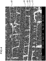
- FIG 4 a corresponding scanning electron microscope image of a micrograph of a material from the prior art is shown. The picture was taken with an accelerating voltage of 15 kV at a magnification of 200 times - corresponding to that in Figure 2 illustrated micrograph of the fiber composite material 40 according to the invention.
- the carbide matrix 24 is not arranged around the individual fiber filaments 19, but rather forms a type of frame for the blocks of fiber filaments 19 and free carbon phase 22.
- the carbide matrix 20 has a volume fraction compared to the material according to FIGS Figures 3 and 4th due to the lack of free carbon phase is increased, a higher thermal conductivity and a greater hardness.
- Embodiments for producing a fiber composite material 40 according to the invention in which there is essentially no free carbon phase in the area of the fiber filaments 19, are shown in FIGS Figures 5 and 6th shown schematically.
- This porous fiber pre-body 35 comprises fibers 45 which are surrounded and / or received by a porous, in particular open-pore structure.
- the porous fiber preform 35 can be produced according to two alternative embodiments.
- fibers 45 are infiltrated with a solvent 46 and a polymer resin 48, in particular a phenolic resin.
- a polymer resin 48 in particular a phenolic resin.
- Novolac for example, has proven to be particularly suitable as a phenolic resin.
- Fiber structures for example woven fabrics, scrims, knitted fabrics, in particular made from fiber bundles, are suitable as fibers 45.
- Furfuryl alcohol for example, is used as the solvent 46. Furfuryl alcohol boils at a temperature which is higher than a temperature at which a curing phase of the polymer resin 48 is carried out and at which the polymer resin 48 polymerizes.
- a mass fraction of the solvent 46 is, for example, 10% based on a total mass of a starting material 42.
- the starting material 42 is formed by the fiber device and the solvent 46.
- the fiber device includes the fibers 45 and the polymer resin 48.
- the mass fraction of the solvent which is in particular furfuryl alcohol, is approximately 50% based on the starting material 42.
- the polymer resin 48 is then cured under pressure, in particular with molding.
- the pressure is typically in a range from 15 bar to 20 bar.
- the polymer resin 46 hardens around the fibers 45, in particular around their fiber filaments 19, while the solvent 46 is enclosed in finely divided liquid form in the hardened polymer resin 48.
- the application of pressure particularly suppresses foaming during the curing phase.
- the solvent 46 is incorporated in finely divided form in the cured and / or curing polymer resin 48. This later ensures a finely distributed porosity for the production of a foam structure or sponge structure.
- the curing takes place, for example, in an autoclave or a corresponding carbon body is produced using an RTM (Resin Transfer Molding) process.
- RTM Resin Transfer Molding
- the cured polymer resin 48 already has a porosity and / or foam structure, for example by using a polyurethane foam. However, this is not absolutely necessary for the method according to the invention.
- the polymer resin 48 cured around the fibers 45 with the enclosed solvent 46 is then subjected to pyrolysis.
- the pyrolysis is carried out, for example, for a certain time with exclusion of oxygen at a temperature of 900 ° C. or more, in particular approximately 1400 ° C. or 1600 ° C.
- the porous fiber preform 35 is formed, since the enclosed solvent 46 escapes due to the high temperatures.
- FIG Figure 8 The structure of the porous fiber pre-body 35, which was produced according to the first alternative, is shown in FIG Figure 8 shown. This will be discussed later.
- the porous fiber preform 35 is then infiltrated with carbide former 49 - in this case silicon.
- Melt phase infiltration is used for carbide-forming infiltration.
- the carbide former 49 is heated to a temperature which is higher than the melting point of the carbide former 49, whereby the carbide former 49 becomes liquid.
- the liquid carbide former 49 then infiltrates the porous fiber preform 35, assisted by capillary forces.
- the liquid and / or solidifying carbide former 49 reacts with the carbon contained in the porous fiber preform 35 to form carbide and forms the in connection with the Figures 1 and 2 carbide matrix 20 described.
- the carbide-forming agent infiltration takes place according to the LSI (Liquid Silicon Infiltration) process.
- LSI Liquid Silicon Infiltration
- Free carbide former may remain within or separately from the carbide matrix 20. If necessary - as already mentioned - residual carbon can be present in areas in which no fiber bundles 16 are arranged.
- the porous fiber pre-body 35 is either open-pored or the walls between the pores are so thin that liquid silicon - which is used here as carbide former 49 - passes through the walls and thus infiltrates the entire porous fiber pre-body 35.
- the high porosity of the porous fiber pre-body 35 ensures that no free carbon phase remains in areas in which fiber bundles 16 are arranged.
- fibers 45 are placed in a container, into which carbon-containing granular material 32, for example a mixture of silicon carbide powder and activated carbon powder, is then filled.
- the granular material 32 particularly encloses the fibers 45.
- pyrolysis is carried out for a certain time at the temperatures mentioned with exclusion of oxygen.
- the particles 30 of the granular material 32 preferably have a size which is of the order of magnitude of the diameter of the pores.
- FIG Figure 9 The structure of the porous fiber preform 35, which was produced according to the second alternative, is shown in FIG Figure 9 shown. This will be discussed later.
- a subsequent carbide former infiltration of the porous fiber preform 35 produced on the basis of granular material 32 is carried out in the same way as the carbide former infiltration of the porous fiber preform 35 produced on the basis of a solvent infiltration (cf. Figure 5 ), so that reference is made to the corresponding statements.
- Figure 7 a scanning electron micrograph of a micrograph of a porous fiber preform 35 is shown. The picture was taken with an acceleration voltage of 5 kV and a magnification of 25 thousand times. The original image was processed using color reversal and tonal value correction.
- Fiber filaments 19 and a porous structure with pores 26 can be seen in the image. These pores 26 have a smaller pore diameter D than the corresponding fiber diameter B.
- the mean pore diameter D is in the order of magnitude of a fiber diameter B (typically about 10 ⁇ m) of fiber filaments 16.
- the mean diameter D of the pores is at least approximately less than or equal to the fiber diameter B.
- a proportion of pores in the porous fiber preform 35 is preferably at least 10% by volume, based on a total volume of the porous fiber preform 35 (without fibers 45).
- the volume fraction of pores 26 in the porous fiber preform 35 is preferably at least 20%.
- the result of the method according to the invention is, at least in the area in which fiber bundles 16 and / or fiber filaments 19 are arranged, a carbide-ceramic fiber composite material 40, which has essentially no free carbon phase, or a carbide-ceramic component 50 of the same type.
- the material produced with silicon as a carbide former is a C / SiC material.
- the elongation at break is comparable to that of a C / C-SiC material (cf. Figures 3 and 4th ).
- the first “C” stands for the carbon fibers.
- a “C” stands for the carbon fibers and a “C” stands for the free carbon phase, which is essentially not present in the fiber composite material 35 according to the invention.
- a carbide-ceramic component 50 made from or comprising a fiber composite material 40 which has been produced according to the method according to the invention can advantageously be used, for example, as a brake disk or as a re-entry shield.
Abstract
Es wird ein Verfahren zur Herstellung eines carbidkeramischen Faserverbundmaterials (40) bereitgestellt, welches das Infiltrieren einer Fasereinrichtung mit einem Lösungsmittel (46) umfasst, wobei die Fasereinrichtung Fasern (45) und ein Polymerharz (48) umfasst und wobei das Lösungsmittel (46) einen Siedepunkt aufweist, welcher größer ist als eine Polymerisationstemperatur des Polymerharzes (48), wobei das Verfahren ferner das Durchführen einer Pyrolyse an der mit dem Lösungsmittel (46) infiltrierten Fasereinrichtung umfasst, wobei ein poröser Faservorkörper (35) hergestellt wird, und wobei das Verfahren ferner das Durchführen einer Carbidbildner-Infiltration an dem porösen Faservorkörper (35) umfasst, wobei ein Faserverbundmaterial (40) entsteht, dessen Faserfilamente (19) und/oder Faserbündel (16) in einer Carbid-Matrix (20) angeordnet sind.

Description
Die Erfindung betrifft ein Verfahren zur Herstellung eines carbidkeramischen Faserverbundmaterials.The invention relates to a method for producing a carbide-ceramic fiber composite material.
Die Erfindung betrifft ferner ein weiteres Verfahren zur Herstellung eines carbidkeramischen Faserverbundmaterials.The invention also relates to a further method for producing a carbide-ceramic fiber composite material.
Weiter betrifft die Erfindung ein carbidkeramisches Bauteil.The invention also relates to a carbide-ceramic component.
Aus der
Die
Die
Aus der
Die
Der Erfindung liegt die Aufgabe zugrunde, ein Verfahren bereitzustellen, mit welchem sich auf einfache Weise ein carbidkeramisches Faserverbundmaterial herstellen lässt und bei welchem ein Anteil an freiem Kohlenstoff möglichst gering ist.The invention is based on the object of providing a method with which a carbide-ceramic fiber composite material can be produced in a simple manner and in which a proportion of free carbon is as low as possible.
Diese Aufgabe wird durch ein Verfahren zur Herstellung eines carbidkeramischen Faserverbundmaterials gelöst, wobei das Verfahren umfasst:
- Infiltrieren einer Fasereinrichtung mit einem Lösungsmittel, wobei die Fasereinrichtung Fasern und ein Polymerharz umfasst und wobei das Lösungsmittel einen Siedepunkt aufweist, welcher größer ist als eine Polymerisationstemperatur des Polymerharzes;
- Durchführen einer Pyrolyse an der mit dem Lösungsmittel infiltrierten Fasereinrichtung, wobei ein poröser Faservorkörper hergestellt wird; und
- Durchführen einer Carbidbildner-Infiltration an dem porösen Faservorkörper, wobei ein Faserverbundmaterial entsteht, dessen Faserfilamente und/oder Faserbündel in einer Carbid-Matrix angeordnet sind.
- Infiltrating a fiber device with a solvent, the fiber device comprising fibers and a polymer resin, and wherein the solvent has a boiling point that is greater than a polymerization temperature of the polymer resin;
- Carrying out a pyrolysis on the fiber device infiltrated with the solvent, a porous fiber preform being produced; and
- Carrying out a carbide-forming agent infiltration on the porous fiber preform, a fiber composite material being produced, the fiber filaments and / or fiber bundles of which are arranged in a carbide matrix.
Durch das Infiltrieren mit einem Lösungsmittel, dessen Siedepunkt größer ist als die Polymerisationstemperatur des Polymerharzes, wird das Lösungsmittel bei einer Herstellung eines Ausgangsmaterials für die Pyrolyse zunächst in flüssiger Form, insbesondere fein verteilt, eingeschlossen. Erst während der Pyrolyse sind die Temperaturen so hoch, dass das Lösungsmittel verdampft und/oder entweicht, wodurch eine Porosität in dem Faservorkörper gebildet wird.By infiltrating with a solvent whose boiling point is higher than the polymerization temperature of the polymer resin, the solvent is initially enclosed in liquid form, in particular finely divided, when a starting material for the pyrolysis is produced. Only during the pyrolysis are the temperatures so high that the solvent evaporates and / or escapes, as a result of which porosity is formed in the fiber preform.
Der poröse Faservorkörper weist durch das gleichmäßige Entweichen des Lösungsmittels insbesondere eine feine Porenverteilung auf. Es lässt sich eine Art von Nanoschwamm oder Nanoschaum als poröser Faservorkörper herstellen.Due to the uniform escape of the solvent, the porous fiber preform has in particular a fine pore distribution. A type of nano sponge or nano foam can be produced as a porous fiber preform.
Durch die poröse Struktur des porösen Faservorkörpers lässt sich insbesondere eine homogene Carbidbildner-Infiltration durchführen.Due to the porous structure of the porous fiber pre-body, a homogeneous carbide-forming agent infiltration can be carried out in particular.
Die Fasereinrichtung und das Lösungsmittel bilden vorzugsweise ein Ausgangsmaterial für den porösen Faservorkörper und/oder für die Pyrolyse.The fiber device and the solvent preferably form a starting material for the porous fiber preform and / or for the pyrolysis.
Es kann vorgesehen sein, dass das Ausgangsmaterial bereits vor der Pyrolyse eine Porosität und/oder Schaumstruktur aufweist.It can be provided that the starting material has a porosity and / or foam structure even before the pyrolysis.
Bei dem Polymerharz handelt es sich vorzugsweise um ein Phenolharz.The polymer resin is preferably a phenolic resin.
Der poröse Faservorkörper ist vorzugsweise ein kohlenstoffhaltiger Vorkörper mit Kohlenstofffasern.The porous fiber preform is preferably a carbon-containing preform with carbon fibers.
Der poröse Faservorkörper ist insbesondere ein offenporöser Faservorkörper beziehungsweise weist eine Offenporosität auf.The porous fiber pre-body is in particular an open-pore fiber pre-body or has an open porosity.
Alternativ oder ergänzend kann vorgesehen sein, dass Wände zwischen (geschlossenen) Poren derart dünn ausgebildet sind, dass bei der Carbidbildner-Infiltration Carbidbildner durch die Wände hindurchtreten und/oder sich durchfressen kann. Es entsteht dadurch gewissermaßen bei der Carbidbildner-Infiltration eine Art von Offenporosität.Alternatively or in addition, it can be provided that walls between (closed) pores are made so thin that carbide formers pass through the walls and / or during the carbide-forming agent infiltration can eat through. This creates a kind of open porosity during the carbide former infiltration.
Bei beiden Alternativen - einer offenporösen Ausbildung des porösen Faservorkörpers sowie bei durch dünne Wände zwischen Poren tretendem Carbidbildner - wird eine Carbidbildner-Infiltration ermöglicht, bei welcher im Wesentlichen der gesamte Kohlenstoff im Faservorkörper (abgesehen von in den Fasern enthaltenem Kohlenstoff) zu Carbid reagiert.With both alternatives - an open-pore design of the porous fiber pre-body as well as carbide former penetrating through thin walls between pores - a carbide-former infiltration is made possible in which essentially all of the carbon in the fiber pre-body (apart from the carbon contained in the fibers) reacts to form carbide.
In der Regel umfassen die Fasern Faserbündel - sogenannte Rovings - welche sich aus einer Mehrzahl von Faserfilamenten zusammensetzen. Die Fasern sind vorzugsweise aus Kohlenstofffaserbündeln gebildet oder umfassen Kohlenstofffaserbündel.As a rule, the fibers comprise fiber bundles - so-called rovings - which are composed of a plurality of fiber filaments. The fibers are preferably formed from carbon fiber bundles or comprise carbon fiber bundles.
Vorzugsweise ist das Lösungsmittel ein Alkohol.Preferably the solvent is an alcohol.
Insbesondere ist das Lösungsmittel Furfurylalkohol, Isopropanol oder eine Mischung daraus.In particular, the solvent is furfuryl alcohol, isopropanol or a mixture thereof.
Ergänzend oder alternativ kann das Lösungsmittel chemische Schaumbildner umfassen oder daraus gebildet sein.Additionally or alternatively, the solvent can comprise chemical foaming agents or be formed therefrom.
Furfurylalkohol ist mit einem Siedepunkt von circa 170°C besonders gut als Lösungsmittel geeignet. Eine Aushärtungsreaktion des Polymerharzes wird insbesondere in einem Bereich von circa 140°C bis circa 160°C, beispielsweise bei circa 150°C, durchgeführt. Während der Aushärtungsreaktion wird der Furfurylalkohol in flüssiger Form, insbesondere fein verteilt, in das aushärtende Polymerharz eingeschlossen und siedet erst bei der Pyrolyse.With a boiling point of around 170 ° C, furfuryl alcohol is particularly suitable as a solvent. A curing reaction of the polymer resin is carried out, in particular, in a range from approximately 140 ° C. to approximately 160 ° C., for example at approximately 150 ° C. During the curing reaction, the furfuryl alcohol is enclosed in liquid form, in particular finely divided, in the curing polymer resin and only boils during pyrolysis.
Die Pyrolyse wird vorzugsweise bei circa 1200°C oder mehr, beispielsweise bei circa 1600°C, - also deutlich oberhalb des Siedepunkts von Furfurylalkohol - durchgeführt.The pyrolysis is preferably carried out at about 1200 ° C. or more, for example at about 1600 ° C., that is to say well above the boiling point of furfuryl alcohol.
Günstig kann es sein, wenn ein Massenanteil des Lösungsmittels in einem Ausgangsmaterial für den porösen Faservorkörper, umfassend die Fasereinrichtung und das Lösungsmittel, mindestens 10 % beträgt.It can be favorable if a mass fraction of the solvent in a starting material for the porous fiber preform, comprising the fiber device and the solvent, is at least 10%.
Gemäß einer bevorzugten Ausführungsform werden die Fasern mit dem Polymerharz und dem Lösungsmittel infiltriert und es wird - wie bereits erwähnt - in einer Aushärtungsphase eine Aushärtungsreaktion des Polymerharzes durchgeführt. Die Aushärtungsreaktion des Polymerharzes wird insbesondere unter Druck durchgeführt.According to a preferred embodiment, the fibers are infiltrated with the polymer resin and the solvent and - as already mentioned - a curing reaction of the polymer resin is carried out in a curing phase. The curing reaction of the polymer resin is carried out in particular under pressure.
Alternativ kann vorgesehen sein, dass sogenannte "Prepregs", also mit einem Polymerharz vorimprägnierte Fasern, verwendet werden.Alternatively, it can be provided that so-called “prepregs”, that is to say fibers pre-impregnated with a polymer resin, are used.
Wie eingangs erwähnt, betrifft die vorliegende Erfindung ferner ein weiteres Verfahren zur Herstellung eines carbidkeramischen Faserverbundmaterials, wobei das Verfahren umfasst:
- Herstellen eines porösen Faservorkörpers unter Verwendung eines kohlenstoffhaltigen granularen Materials und Fasern, wobei das kohlenstoffhaltige granulare Material und die Fasern pyrolysiert werden; und
- Durchführen einer Carbidbildner-Infiltration an dem porösen Faservorkörper, wobei ein Faserverbundmaterial entsteht, dessen Faserfilamente und/oder Faserbündel in einer Carbid-Matrix angeordnet sind.
- Making a porous fiber preform using a carbonaceous granular material and fibers, wherein the carbonaceous granular material and the fibers are pyrolyzed; and
- Carrying out a carbide-forming agent infiltration on the porous fiber preform, a fiber composite material being produced, the fiber filaments and / or fiber bundles of which are arranged in a carbide matrix.
Ein Polymerharz ist insbesondere entbehrlich.In particular, a polymer resin can be dispensed with.
Je nach Anwendungsfall kann jedoch auch vorgesehen sein, dass granulares Material und eine Fasereinrichtung pyrolysiert werden.Depending on the application, however, provision can also be made for granular material and a fiber device to be pyrolyzed.
Das kohlenstoffhaltige granulare Material ist vorzugsweise ein Pulver und umfasst insbesondere eines oder mehrere der folgenden Materialien in Pulverform oder ist daraus gebildet: Siliziumcarbid, Aktivkohle.The carbon-containing granular material is preferably a powder and in particular comprises one or more of the following materials in powder form or is formed therefrom: silicon carbide, activated carbon.
Vorteilhaft kann es sein, wenn das kohlenstoffhaltige granulare Material als lose Schüttung um die Fasern herum angeordnet wird, bevor die Pyrolyse durchgeführt wird.It can be advantageous if the carbonaceous granular material is arranged as a loose bed around the fibers before the pyrolysis is carried out.
Die nachfolgend aufgeführten Merkmale und/oder Vorteile gelten für beide Verfahren gleichermaßen.The features and / or advantages listed below apply equally to both methods.
Es kann vorgesehen sein, dass die Carbid-Matrix freien Carbidbildner, welcher nicht mit Kohlenstoff regiert hat, umfasst.It can be provided that the carbide matrix comprises free carbide former which did not react with carbon.
Vorzugsweise ist die Carbid-Matrix frei von freiem Kohlenstoff oder arm an freiem Kohlenstoff.The carbide matrix is preferably free of free carbon or poor in free carbon.
Insbesondere ist zwischen den Faserfilamenten und/oder Faserbündeln in dem Faserverbundmaterial im Wesentlichen keine freie Kohlenstoffphase vorhanden.In particular, there is essentially no free carbon phase between the fiber filaments and / or fiber bundles in the fiber composite material.
Günstig kann es sein, wenn eine Vereinzelung von Faserfilamenten einer Faserverstärkung stattfindet. Insbesondere bleiben Faserfilamente in dem resultierenden carbidkeramischen Faserverbundmaterial erhalten. Eine Schädigung der Faserfilamente wird insbesondere vermieden.It can be beneficial if the fiber filaments of a fiber reinforcement are separated. In particular, fiber filaments are retained in the resulting carbide-ceramic fiber composite material. In particular, damage to the fiber filaments is avoided.
Der poröse Faservorkörper wird insbesondere als Schwammkörper oder Schaumkörper und insbesondere als Nanoschwammkörper oder Nanoschaumkörper hergestellt.The porous fiber pre-body is produced in particular as a sponge body or foam body and in particular as a nano sponge body or nano foam body.
Eine Porosität des porösen Faservorkörpers beträgt vorzugsweise mindestens 10 Volumen-%, insbesondere mindestens 15 Volumen-%, insbesondere mindestens 20 Volumen-%, bezogen auf ein Gesamtvolumen des porösen Faservorkörpers, insbesondere ohne einen Volumenanteil einer Faserverstärkung.A porosity of the porous fiber pre-body is preferably at least 10% by volume, in particular at least 15% by volume, in particular at least 20% by volume, based on a total volume of the porous fiber pre-body, in particular without a volume fraction of a fiber reinforcement.
Vorzugsweise umfasst der poröse Faservorkörper Poren mit einem mittleren Porendurchmesser, welcher kleiner oder gleich 20 µm ist und insbesondere kleiner oder gleich 15 µm ist und insbesondere kleiner oder gleich 10 µm ist.The porous fiber preform preferably comprises pores with an average pore diameter which is less than or equal to 20 μm and in particular is less than or equal to 15 μm and in particular is less than or equal to 10 μm.
Vorzugsweise werden die Fasern durch Faserbündel mit einer Mehrzahl von Faserfilamenten hergestellt.The fibers are preferably produced by fiber bundles with a plurality of fiber filaments.
Ein Faserbündel umfasst vorzugsweise circa 3000 bis circa 12000 Faserfilamente.A fiber bundle preferably comprises from about 3000 to about 12000 fiber filaments.
Es kann vorgesehen sein, dass ein mittlerer Porendurchmesser im porösen Faservorkörper mindestens näherungsweise kleiner als ein Faserdurchmesser ist oder mindestens näherungsweise dem Faserdurchmesser entspricht. Der Faserdurchmesser bezeichnet vorzugsweise einen Durchmesser eines Faserfilaments.It can be provided that a mean pore diameter in the porous fiber preform is at least approximately smaller than a fiber diameter or at least approximately corresponds to the fiber diameter. The fiber diameter preferably denotes a diameter of a fiber filament.
Vorteilhaft kann es sein, wenn die Fasern ein Gewebe, ein Gelege, ein Gewirke und/oder Kurzfasern umfassen. Die Fasern sind insbesondere aus einer Mehrzahl von Faserfilamenten zusammengesetzt.It can be advantageous if the fibers comprise a woven fabric, a scrim, a knitted fabric and / or short fibers. In particular, the fibers are composed of a plurality of fiber filaments.
Beispielsweise sind das Gewebe, das Gelege, das Gewirke und/oder die Kurzfasern aus Faserbündeln mit einer Mehrzahl von Faserfilamenten zusammengesetzt.For example, the woven fabric, the scrim, the knitted fabric and / or the short fibers are composed of fiber bundles with a plurality of fiber filaments.
Gemäß einer bevorzugten Ausführungsform wird als Carbidbildner Silizium verwendet. Es lässt sich so insbesondere ein C/SiC-Material herstellen. Grundsätzlich sind aber auch andere Carbidbildner, wie beispielsweise Titan oder Wolfram, für das Verfahren geeignet.According to a preferred embodiment, silicon is used as the carbide former. In particular, a C / SiC material can be produced in this way. In principle, however, other carbide formers, such as titanium or tungsten, are also suitable for the process.
Das erfindungsgemäße Faserverbundmaterial weist vorzugsweise eine erhöhte Wärmeleitfähigkeit, eine erhöhte Hochtemperaturoxidationsbeständigkeit und/oder eine erhöhte Abrasionsbeständigkeit auf.The fiber composite material according to the invention preferably has an increased thermal conductivity, an increased high-temperature oxidation resistance and / or an increased abrasion resistance.
Wie eingangs erwähnt, betrifft die vorliegende Erfindung ferner ein carbidkeramisches Bauteil, wobei das carbidkeramische Bauteil ein Faserverbundmaterial, welches nach einem erfindungsgemäßen Verfahren hergestellt ist, umfasst oder daraus besteht.As mentioned at the beginning, the present invention also relates to a carbide-ceramic component, the carbide-ceramic component comprising or consisting of a fiber composite material which is produced by a method according to the invention.
Günstig kann es sein, wenn das carbidkeramische Bauteil eine Biegefestigkeit von mindestens 150 MPa aufweist.It can be favorable if the carbide-ceramic component has a flexural strength of at least 150 MPa.
Vorzugsweise weist das carbidkeramische Bauteil eine Bruchdehnung im Biegeversuch von mindestens 0,15 %, insbesondere von mindestens 0,2 %, auf.The carbide-ceramic component preferably has an elongation at break in the bending test of at least 0.15%, in particular of at least 0.2%.
Die im Zusammenhang mit dem erfindungsgemäßen Verfahren genannten Merkmale und/oder Vorteile gelten für das erfindungsgemäße carbidkeramische Bauteil vorzugsweise gleichermaßen.The features and / or advantages mentioned in connection with the method according to the invention preferably apply equally to the carbide-ceramic component according to the invention.
Ein carbidkeramisches Bauteil lässt sich vorteilhafterweise als Bremsscheibe beziehungsweise als Teil einer Bremsscheibe verwenden.A carbide ceramic component can advantageously be used as a brake disk or as part of a brake disk.
Alternativ lässt sich das carbidkeramische Bauteil auch als Hitzeschild bei Raumfahrtanwendungen, wie beispielsweise für den Wiedereintritt in die Erdatmosphäre, oder allgemein im Bereich der Luftfahrt, beispielsweise in Triebwerkskomponenten, einsetzen.Alternatively, the carbide ceramic component can also be used as a heat shield in space applications, such as for re-entry into the earth's atmosphere, or in general in the field of aviation, for example in engine components.
Weitere bevorzugte Anwendungsbereiche für das erfindungsgemäße carbidkeramische Faserverbundmaterial sind die Energietechnik, beispielsweise Infusionsreaktoren oder Solaröfen, Gleitlager in unterschiedlichen Bereichen, Brennkammern und Verbrennungsanlagen.Further preferred areas of application for the carbide-ceramic fiber composite material according to the invention are energy technology, for example infusion reactors or solar ovens, slide bearings in different areas, combustion chambers and incineration plants.
Die nachfolgende Beschreibung bevorzugter Ausführungsformen dient im Zusammenhang mit den Zeichnungen der näheren Erläuterung der Erfindung.The following description of preferred embodiments is used in conjunction with the drawings to explain the invention in greater detail.
Es zeigen:
- Figur 1
- eine schematische Schnittdarstellung eines Ausführungsbeispiels eines erfindungsgemäßen Faserverbundmaterials als C/SiC-Werkstoff;
- Figur 2
- eine Rasterelektronenmikroskopieaufnahme eines Schliffbilds eines erfindungsgemäßen C/SiC-Werkstoffs;
- Figur 3
- eine schematische Schnittdarstellung eines eines C/C-SiC-Werkstoffs aus dem Stand der Technik;
- Figur 4
- eine Rasterelektronenmikroskopieaufnahme eines Schliffbilds eines C/C-SiC-Werkstoffs gemäß der Schnittdarstellung aus
Figur 3 ; - Figur 5
- eine schematische Darstellung einer Ausführungsform eines erfindungsgemäßen Verfahrens zur Herstellung eines Faserverbundmaterials;
- Figur 6
- eine schematische Darstellung einer weiteren Ausführungsform eines erfindungsgemäßen Verfahrens zur Herstellung eines Faserverbundmaterials;
- Figur 7
- eine Rasterelektronenmikroskopieaufnahme (nach Bildbearbeitung) eines Schliffbilds eines porösen Faservorkörpers mit Kohlenstofffasern zwischen Faserbündeln nach einer Pyrolyse, wobei der poröse Faservorkörper schwammartig ist und mit Carbidbildner infiltrierbar ist;
- Figur 8
- eine schematische Schnittdarstellung einer Struktur eines porösen Faservorkörpers, bei welchem ein kohlenstoffhaltiger Schaum um Faserfilamente herum angeordnet ist; und
- Figur 9
- eine schematische Schnittdarstellung einer Struktur eines porösen Faservorkörpers, bei welchem ein granulares Material um Faserfilamente herum angeordnet ist.
- Figure 1
- a schematic sectional view of an embodiment of a fiber composite material according to the invention as a C / SiC material;
- Figure 2
- a scanning electron microscope image of a micrograph of a C / SiC material according to the invention;
- Figure 3
- a schematic sectional illustration of a C / C-SiC material from the prior art;
- Figure 4
- a scanning electron microscope image of a micrograph of a C / C-SiC material according to the sectional illustration
Figure 3 ; - Figure 5
- a schematic representation of an embodiment of a method according to the invention for producing a fiber composite material;
- Figure 6
- a schematic representation of a further embodiment of a method according to the invention for producing a fiber composite material;
- Figure 7
- a scanning electron microscope image (after image processing) of a micrograph of a porous fiber preform with carbon fibers between fiber bundles after pyrolysis, the porous fiber preform being spongy and infiltratable with carbide former;
- Figure 8
- a schematic sectional view of a structure of a porous fiber preform in which a carbon-containing foam is arranged around fiber filaments; and
- Figure 9
- a schematic sectional view of a structure of a porous fiber preform, in which a granular material is arranged around fiber filaments.
Gleiche oder funktional äquivalente Elemente sind in sämtlichen Figuren mit denselben Bezugszeichen versehen.Identical or functionally equivalent elements are provided with the same reference symbols in all figures.
Es wird ein carbidkeramisches Faserverbundmaterial 40 bereitgestellt, welches vorliegend ein carbidkeramisches Bauteil 50 bildet. Das Faserverbundmaterial 40 weist eine Faserverstärkung 10 auf.A carbide-ceramic
In dem carbidkeramischen Faserverbundmaterial 40 liegt - zumindest im Bereich der Faserverstärkung 10 - im Wesentlichen keine freie Kohlenstoffphase vor.In the carbide-ceramic
Die Faserverstärkung 10 umfasst vorzugsweise Kohlenstofffasern, insbesondere in Form von Faserbündeln 16 - sogenannte Rovings - welche in einer 0°-Orientierung 12 und einer 90°-Orientierung 14 bezogen auf eine Ansichtsrichtung angeordnet sind (vgl.
Die Faserbündel 16 umfassen beispielsweise circa 3000 einzelne Faserfilamente 19, von welchen in den
Die einzelnen Faserfilamente 19 sind von einer Carbid-Matrix 20 und/oder freiem Carbidbildner 18 aufgenommen und/oder darin eingebettet.The
Der freie Carbidbildner 18 hat nicht mit Kohlenstoff reagiert und bildet einen Teil der Carbid-Matrix 20. Die Carbid-Matrix 20 enthält Carbid, welches durch eine Reaktion von Carbidbildner und Kohlenstoff entstanden ist und/oder - wie erwähnt - freien Carbidbildner, welcher nicht mit Kohlenstoff reagiert hat.The free carbide former 18 has not reacted with carbon and forms part of the
Wie bereits erwähnt, enthält das Faserverbundmaterial 40 im Bereich der Faserbündel 16 vorliegend keine freie Kohlenstoffphase.As already mentioned, the
Außerhalb eines Bereichs, in welchem die Faserbündel 16 angeordnet sind, kann grundsätzlich eine freie Kohlenstoffphase mit einem geringen Volumenanteil vorliegen.Outside an area in which the fiber bundles 16 are arranged, a free carbon phase with a low volume fraction can in principle be present.
Ein Durchmesser eines Faserfilaments 19 beträgt typischerweise circa 10 µm.A diameter of a
Wie bereits erwähnt, hat das Faserbündel 16 vorliegend 3000 Faserfilamente 19, wobei dies typischerweise als 3 K bezeichnet wird. Grundsätzlich sind Faserbündel 16 mit einem Wert von 3 K bis 12 K besonders geeignet. Eine weitere charakteristische Angabe für Faserbündel ist deren Feinheit, wobei eine längenbezogene Masse in tex angegeben wird. Ein tex entspricht 1 g/1000 m.As already mentioned, the
In
Als Carbidbildner wurde vorliegend Silizium verwendet. Die Faserverstärkung 10 ist vorliegend aus Kohlenstoff-Faserbündeln. Die einzelnen Faserfilamente 19 sind in dem mit einem Rasterelektronenmikroskop aufgenommenen Bild dunkel abgebildet, während das während einer Reaktion zwischen Kohlenstoff und Carbidbildner entstandene Siliziumcarbid vom Rasterelektronenmikroskop hell abgebildet wird.In the present case, silicon was used as the carbide former. The
Aus
Im Vergleich hierzu ist in
In
Um die Faserfilamente 19 herum sind dunklere Bereiche zu sehen, welche von der freien Kohlenstoffphase 22 resultieren.Darker areas, which result from the
Bei der Pyrolyse ist es zu einer Rissbildung gekommen. Durch diese Risse kann der Carbidbildner bei einer Carbidbildner-Infiltration leichter in den Körper eindringen. An Stellen, an welchen die Risse waren, entsteht daher vermehrt Carbid.Cracks have formed during pyrolysis. Through these cracks, the carbide former can more easily penetrate the body during a carbide former infiltration. Carbide is therefore increasingly formed in places where the cracks were.
Die Carbid-Matrix 24 ist - im Unterschied zu dem erfindungsgemäßen Faserverbundmaterial 40 - nicht um die einzelnen Faserfilamente 19 herum angeordnet, sondern bildet eine Art Rahmen für die Blöcke aus Faserfilamenten 19 und freier Kohlenstoffphase 22.In contrast to the
Bei dem erfindungsgemäßen Faserverbundmaterial 40 (
Ferner ergibt sich durch die Carbid-Matrix 20, deren Volumenanteil im Vergleich zu dem Material gemäß den
Ausführungsbeispiele zur Herstellung eines erfindungsgemäßen Faserverbundmaterials 40, bei welchem im Bereich der Faserfilamente 19 im Wesentlichen keine freie Kohlenstoffphase vorhanden ist, sind in den
Es wird zunächst ein poröser Faservorkörper 35 hergestellt. Dieser poröse Faservorkörper 35 umfasst Fasern 45, welche von einer porösen, insbesondere offenporösen Struktur, umgeben und/oder aufgenommen sind.First, a
Der poröse Faservorkörper 35 kann gemäß zwei alternativen Ausführungsformen hergestellt werden.The
Gemäß einer ersten in
Als Fasern 45 sind beispielsweise Fasergebilde, beispielsweise Gewebe, Gelege, Gewirke, insbesondere aus Faserbündeln geeignet.Fiber structures, for example woven fabrics, scrims, knitted fabrics, in particular made from fiber bundles, are suitable as
Als Lösungsmittel 46 wird beispielsweise Furfurylalkohol verwendet. Furfurylalkohol siedet bei einer Temperatur, welche größer als eine Temperatur ist, bei der eine Aushärtungsphase des Polymerharzes 48 durchgeführt wird und bei welcher das Polymerharz 48 polymerisiert.Furfuryl alcohol, for example, is used as the solvent 46. Furfuryl alcohol boils at a temperature which is higher than a temperature at which a curing phase of the
Ein Massenanteil des Lösungsmittels 46 beträgt beispielsweise 10 % bezogen auf eine Gesamtmasse eines Ausgangsmaterials 42. Das Ausgangsmaterial 42 wird von der Fasereinrichtung und dem Lösungsmittel 46 gebildet. Die Fasereinrichtung umfasst die Fasern 45 und das Polymerharz 48.A mass fraction of the solvent 46 is, for example, 10% based on a total mass of a starting
Bei einem Ausführungsbeispiel liegt der Massenanteil des Lösungsmittels, welches insbesondere Furfurylalkohol ist, bei circa 50 % bezogen auf das Ausgangsmaterial 42.In one embodiment, the mass fraction of the solvent, which is in particular furfuryl alcohol, is approximately 50% based on the starting
Das Polymerharz 48 wird dann, insbesondere mit Formgebung, unter Druck ausgehärtet. Der Druck liegt typischerweise in einem Bereich von 15 bar bis 20 bar. Dabei härtet das Polymerharz 46 um die Fasern 45, insbesondere um deren Faserfilamente 19, aus, während das Lösungsmittel 46 fein verteilt in flüssiger Form in dem ausgehärteten Polymerharz 48 eingeschlossen wird.The
Die Druckbeaufschlagung unterdrückt insbesondere ein Aufschäumen während der Aushärtungsphase. Unter Druckbeaufschlagung wird das Lösungsmittel 46 fein verteilt in dem ausgehärteten und/oder aushärtenden Polymerharz 48 eingelagert. Dies sorgt später für eine fein verteilte Porosität zur Herstellung einer Schaumstruktur oder Schwammstruktur.The application of pressure particularly suppresses foaming during the curing phase. When pressure is applied, the solvent 46 is incorporated in finely divided form in the cured and / or curing
Es hat sich gezeigt, dass bei einer Aushärtung unter Normaldruck bereits während der Aushärtungsphase ein starkes Aufschäumen erfolgt.It has been shown that when hardening under normal pressure, strong foaming already takes place during the hardening phase.
Die Aushärtung erfolgt beispielsweise in einem Autoklaven oder es wird über ein RTM (Resin Transfer Molding)-Verfahren ein entsprechender Kohlenstoffkörper hergestellt.The curing takes place, for example, in an autoclave or a corresponding carbon body is produced using an RTM (Resin Transfer Molding) process.
Es kann vorgesehen sein, dass bereits das ausgehärtete Polymerharz 48 eine Porosität und/oder Schaumstruktur aufweist, beispielsweise durch Verwendung eines Polyurethanschaums. Dies ist für das erfindungsgemäße Verfahren jedoch nicht zwingend notwendig.It can be provided that the cured
Das um die Fasern 45 ausgehärtete Polymerharz 48 mit dem eingeschlossenen Lösungsmittel 46 wird anschließend einer Pyrolyse unterzogen. Die Pyrolyse wird beispielsweise für eine bestimmte Zeit unter Sauerstoffausschluss bei einer Temperatur von 900°C oder mehr, insbesondere circa 1400°C oder 1600°C, durchgeführt.The
Während der Pyrolyse entsteht der poröse Faservorkörper 35, da das eingeschlossene Lösungsmittel 46 durch die hohen Temperaturen entweicht.During the pyrolysis, the
Die Struktur des porösen Faservorkörpers 35, welcher gemäß der ersten Alternative hergestellt wurde, ist in
Der poröse Faservorkörper 35 wird anschließend mit Carbidbildner 49 - vorliegend Silizium - infiltriert.The
Zur Carbidbildner-Infiltration wird eine Schmelzphasen-Infiltration eingesetzt. Der Carbidbildner 49 wird auf eine Temperatur, welche größer als der Schmelzpunkt des Carbidbildners 49 ist, erhitzt, wodurch der Carbidbildner 49 flüssig wird. Der flüssige Carbidbildner 49 infiltriert dann - durch KapillarKräfte begünstigt - den porösen Faservorkörper 35.Melt phase infiltration is used for carbide-forming infiltration. The carbide former 49 is heated to a temperature which is higher than the melting point of the carbide former 49, whereby the carbide former 49 becomes liquid. The liquid carbide former 49 then infiltrates the
Der flüssige und/oder erstarrende Carbidbildner 49 reagiert mit dem in dem porösen Faservorkörper 35 enthaltenen Kohlenstoff zu Carbid und bildet die im Zusammenhang mit den
Beispielsweise erfolgt die Carbidbildner-Infiltration gemäß dem LSI (Liquid Silicon Infiltration) Verfahren.For example, the carbide-forming agent infiltration takes place according to the LSI (Liquid Silicon Infiltration) process.
Innerhalb oder separat von der Carbid-Matrix 20 verbleibt gegebenenfalls freier Carbidbildner. Gegebenenfalls kann - wie bereits erwähnt - in Bereichen, in welche keine Faserbündel 16 angeordnet sind, Restkohlenstoff vorhanden sein.Free carbide former may remain within or separately from the
Der poröse Faservorkörper 35 ist entweder offenporös ausgebildet oder die Wände zwischen den Poren sind so dünn, dass flüssiges Silizium - welches vorliegend als Carbidbildner 49 eingesetzt wird - durch die Wände hindurchtritt und so den gesamten porösen Faservorkörper 35 infiltriert.The
Die hohe Porosität des porösen Faservorkörpers 35 sorgt dafür, dass keine freie Kohlenstoffphase in Bereichen, in welchen Faserbündel 16 angeordnet sind, verbleibt.The high porosity of the
Gemäß der in
Auch gemäß der zweiten Alternative wird wie im Zusammenhang mit der ersten Alternative eine Pyrolyse für eine bestimmte Zeit bei den genannten Temperaturen unter Sauerstoffausschluss durchgeführt.According to the second alternative, as in connection with the first alternative, pyrolysis is carried out for a certain time at the temperatures mentioned with exclusion of oxygen.
Durch den Einschluss von Luft zwischen einzelnen Partikeln 30, welche während der Pyrolyse entweicht, entsteht während der Pyrolyse analog zur ersten Alternative ein poröser Faservorkörper 35.As a result of the inclusion of air between
Die Partikel 30 des granularen Materials 32 weisen vorzugsweise eine Größe auf, welche in einer Größenordnung des Durchmessers der Poren liegt.The
Die Struktur des porösen Faservorkörpers 35, welcher gemäß der zweiten Alternative hergestellt wurde, ist in
Eine nachfolgende Carbidbildner-Infiltration des basierend auf granularem Material 32 hergestellten porösen Faservorkörpers 35 wird wie die Carbidbildner-Infiltration des basierend auf einer Lösungsmittel-Infiltration hergestellten porösen Faservorkörpers 35 durchgeführt (vgl.
In
Es sind Faserfilamente 19 und eine poröse Struktur mit Poren 26 auf dem Bild zu erkennen. Diese Poren 26 weisen einen kleineren Porendurchmesser D auf als der entsprechende Faserdurchmesser B.
Alternativ liegt der mittlere Porendurchmesser D in der Größenordnung eines Faserdurchmessers B (typischerweise circa 10 µm) von Faserfilamenten 16. Vorzugsweise ist der mittlere Durchmesser D der Poren mindestens näherungsweise kleiner als oder gleich dem Faserdurchmesser B.Alternatively, the mean pore diameter D is in the order of magnitude of a fiber diameter B (typically about 10 µm) of
In
Ein Porenanteil in dem porösen Faservorkörper 35 beträgt vorzugsweise mindestens 10 Volumen-% bezogen auf ein Gesamtvolumen des porösen Faservorkörpers 35 (ohne Fasern 45).A proportion of pores in the
Wenn beispielsweise ein Faseranteil von 50 % vorhanden ist, dann ist vorzugsweise der Volumenanteil von Poren 26 im porösen Faservorkörper 35 mindestens 20 %.If, for example, there is a fiber content of 50%, then the volume fraction of
Wie bereits erwähnt, ist das Ergebnis des erfindungsgemäßen Verfahrens zumindest im Bereich, in welchem Faserbündel 16 und/oder Faserfilamente 19 angeordnet sind, ein carbidkeramisches Faserverbundmaterial 40, welches im Wesentlichen keine freie Kohlenstoffphase aufweist, beziehungsweise ein ebensolches carbidkeramisches Bauteil 50.As already mentioned, the result of the method according to the invention is, at least in the area in which fiber bundles 16 and / or
Dadurch, dass keine freie Kohlenstoffphase in Bereichen, in welchen Faserbündel 16 und/oder Faserfilamente 19 angeordnet sind, vorhanden ist, ist eine Oxidationsanfälligkeit des Materials minimiert. Daraus resultiert eine hohe Korrosionsbeständigkeit des Faserverbundmaterials 35 beziehungsweise des carbidkeramischen Bauteils 50. Ferner erhält man aufgrund eines höheren Volumenanteils an Carbid-Matrix 20 - aufgrund der fehlenden oder nur gering vorhandenen freien Kohlenstoffphase - eine höhere Wärmeleitfähigkeit und eine größere Härte als in Materialien mit freier Kohlenstoffphase.Because there is no free carbon phase in areas in which fiber bundles 16 and / or
Es ergibt sich eine hohe Biegefestigkeit im Biegeversuch von 150 MPa oder mehr. Beispielsweise lässt sich eine Biegefestigkeit von circa 200 MPa erreichen.A high flexural strength of 150 MPa or more results in the flexural test. For example, a flexural strength of around 200 MPa can be achieved.
Es ergibt sich ferner eine hohe Bruchdehnung von circa 0,3 %.There is also a high elongation at break of around 0.3%.
Das hergestellte Material mit Silizium als Carbidbildner ist ein C/SiC-Material. Die Bruchdehnung ist vergleichbar mit der eines C/C-SiC-Materials (vgl.
In den erstgenannten Materialien steht das erste "C" für die Kohlenstofffasern. In dem zweitgenannten Material steht ein "C" für die Kohlenstofffasern und ein "C" für die freie Kohlenstoffphase, welche bei dem erfindungsgemäßen Faserverbundmaterial 35 im Wesentlichen nicht vorhanden ist.In the former, the first "C" stands for the carbon fibers. In the second-mentioned material, a “C” stands for the carbon fibers and a “C” stands for the free carbon phase, which is essentially not present in the
Ein carbidkeramisches Bauteil 50 aus oder umfassend ein Faserverbundmaterial 40, welches nach dem erfindungsgemäßen Verfahren hergestellt wurde, lässt sich beispielsweise vorteilhafterweise als Bremsscheibe oder als Wiedereintrittschild verwenden.A carbide-
- 1010
- FaserverstärkungFiber reinforcement
- 1212
- 0°-Orientierung0 ° orientation
- 1414th
- 90°-Orientierung90 ° orientation
- 1616
- FaserbündelFiber bundle
- 1818th
- freier Carbidbildnerfree carbide former
- 1919th
- FaserfilamentFiber filament
- 2020th
- Carbid-MatrixCarbide matrix
- 2222nd
- KohlenstoffphaseCarbon phase
- 2424
- Carbid-MatrixCarbide matrix
- 2626th
- PorenPores
- 3030th
- PartikelParticles
- 3232
- granulares Materialgranular material
- 3535
- poröser Faservorkörperporous fiber preform
- 4040
- FaserverbundmaterialFiber composite material
- 4242
- AusgangsmaterialSource material
- 4545
- FasernFibers
- 4646
- Lösungsmittelsolvent
- 4848
- PolymerharzPolymer resin
- 4949
- CarbidbildnerCarbide formers
- 5050
- carbidkeramisches Bauteilcarbide ceramic component
- BB.
- FaserdurchmesserFiber diameter
- DD.
- PorendurchmesserPore diameter
Claims (15)
und/oder
dass das kohlenstoffhaltige granulare Material (32) als lose Schüttung um die Fasern (45) herum angeordnet wird, bevor die Pyrolyse durchgeführt wird.Method according to Claim 4, characterized in that the carbon-containing granular material (32) is a powder and in particular comprises one or more of the following materials in powder form or is formed therefrom: silicon carbide, activated carbon
and or
that the carbon-containing granular material (32) is arranged as a loose bed around the fibers (45) before the pyrolysis is carried out.
Applications Claiming Priority (1)
| Application Number | Priority Date | Filing Date | Title |
|---|---|---|---|
| DE102019111701.1A DE102019111701A1 (en) | 2019-05-06 | 2019-05-06 | Process for the production of a carbide-ceramic fiber composite material and carbide-ceramic component |
Publications (1)
| Publication Number | Publication Date |
|---|---|
| EP3736255A1 true EP3736255A1 (en) | 2020-11-11 |
Family
ID=70480149
Family Applications (1)
| Application Number | Title | Priority Date | Filing Date |
|---|---|---|---|
| EP20172147.9A Pending EP3736255A1 (en) | 2019-05-06 | 2020-04-29 | Method for producing carbide ceramic fibre composite and carbide ceramic component |
Country Status (2)
| Country | Link |
|---|---|
| EP (1) | EP3736255A1 (en) |
| DE (1) | DE102019111701A1 (en) |
Cited By (3)
| Publication number | Priority date | Publication date | Assignee | Title |
|---|---|---|---|---|
| CN114425827A (en) * | 2021-10-21 | 2022-05-03 | 南京玻璃纤维研究设计院有限公司 | Method for preparing prefabricated body based on 3D printing |
| CN114671695A (en) * | 2022-03-01 | 2022-06-28 | 施远 | Carbide composite material and production method and product thereof |
| CN114671694A (en) * | 2022-03-01 | 2022-06-28 | 施远 | Carbide composite material and production method and product thereof |
Citations (7)
| Publication number | Priority date | Publication date | Assignee | Title |
|---|---|---|---|---|
| EP1008569A1 (en) * | 1998-12-09 | 2000-06-14 | ECM Ingenieur-Unternehmen für Energie-und Umwelttechnik GmbH | Method of making a short carbon fibre-reinforced silicon carbide composite material |
| DE19944345A1 (en) | 1999-09-16 | 2001-03-22 | Sgl Technik Gmbh | Composite material reinforced with fibers and / or fiber bundles with a ceramic matrix |
| DE19962548A1 (en) * | 1999-12-23 | 2001-07-12 | Daimler Chrysler Ag | Production of fiber-reinforced composite ceramic comprises impregnating fiber bundles with binders, mixing with carbon fillers and phenol resins, filling into mold, partially drying, pressing, carbonizing |
| DE10011013A1 (en) | 2000-03-07 | 2001-09-20 | Schunk Kohlenstofftechnik Gmbh | Production of carbon foam, used as insulator, catalyst, core material for sandwich structure or reinforcing material or for tribological application or part, involves foaming mixture of carbonizable polymer and blowing agent and pyrolysis |
| US20020179225A1 (en) | 2000-03-24 | 2002-12-05 | Thomas Behr | Fiber-reinforced structural component |
| WO2008007401A1 (en) * | 2006-07-14 | 2008-01-17 | Brembo Ceramic Brake Systems S.P.A. | Braking band composite structure |
| DE102011001065A1 (en) | 2010-03-04 | 2011-09-08 | Deutsches Zentrum für Luft- und Raumfahrt e.V. | Carbide ceramic material, which is produced by carbide former-infiltration of preform containing porous carbon, for glass-fiber reinforced plastic component, comprises a mass portion of free carbon and a mass portion of free carbide former |
-
2019
- 2019-05-06 DE DE102019111701.1A patent/DE102019111701A1/en active Pending
-
2020
- 2020-04-29 EP EP20172147.9A patent/EP3736255A1/en active Pending
Patent Citations (8)
| Publication number | Priority date | Publication date | Assignee | Title |
|---|---|---|---|---|
| EP1008569A1 (en) * | 1998-12-09 | 2000-06-14 | ECM Ingenieur-Unternehmen für Energie-und Umwelttechnik GmbH | Method of making a short carbon fibre-reinforced silicon carbide composite material |
| DE19944345A1 (en) | 1999-09-16 | 2001-03-22 | Sgl Technik Gmbh | Composite material reinforced with fibers and / or fiber bundles with a ceramic matrix |
| DE19962548A1 (en) * | 1999-12-23 | 2001-07-12 | Daimler Chrysler Ag | Production of fiber-reinforced composite ceramic comprises impregnating fiber bundles with binders, mixing with carbon fillers and phenol resins, filling into mold, partially drying, pressing, carbonizing |
| DE10011013A1 (en) | 2000-03-07 | 2001-09-20 | Schunk Kohlenstofftechnik Gmbh | Production of carbon foam, used as insulator, catalyst, core material for sandwich structure or reinforcing material or for tribological application or part, involves foaming mixture of carbonizable polymer and blowing agent and pyrolysis |
| US20020179225A1 (en) | 2000-03-24 | 2002-12-05 | Thomas Behr | Fiber-reinforced structural component |
| WO2008007401A1 (en) * | 2006-07-14 | 2008-01-17 | Brembo Ceramic Brake Systems S.P.A. | Braking band composite structure |
| EP2046700B1 (en) | 2006-07-14 | 2019-09-11 | Freni Brembo S.p.A. | Braking band composite structure |
| DE102011001065A1 (en) | 2010-03-04 | 2011-09-08 | Deutsches Zentrum für Luft- und Raumfahrt e.V. | Carbide ceramic material, which is produced by carbide former-infiltration of preform containing porous carbon, for glass-fiber reinforced plastic component, comprises a mass portion of free carbon and a mass portion of free carbide former |
Cited By (3)
| Publication number | Priority date | Publication date | Assignee | Title |
|---|---|---|---|---|
| CN114425827A (en) * | 2021-10-21 | 2022-05-03 | 南京玻璃纤维研究设计院有限公司 | Method for preparing prefabricated body based on 3D printing |
| CN114671695A (en) * | 2022-03-01 | 2022-06-28 | 施远 | Carbide composite material and production method and product thereof |
| CN114671694A (en) * | 2022-03-01 | 2022-06-28 | 施远 | Carbide composite material and production method and product thereof |
Also Published As
| Publication number | Publication date |
|---|---|
| DE102019111701A1 (en) | 2020-11-12 |
Similar Documents
| Publication | Publication Date | Title |
|---|---|---|
| EP3736255A1 (en) | Method for producing carbide ceramic fibre composite and carbide ceramic component | |
| EP0864548B1 (en) | Graphite short fibre reinforced silicon carbide body | |
| EP1008569B1 (en) | Method of making a short carbon fibre-reinforced silicon carbide composite material | |
| DE60022065T2 (en) | PARTICLE-CONTAINING FOAM BASED ON PECH | |
| DE3045523A1 (en) | "METHOD FOR PRODUCING A SILICON CARBIDE-SILICON MATRIX CERAMIC, MOLDED CERAMIC AND SILICIUM CARBIDE-SILICIUM MATRIX COMPOSITE CERAMIC" | |
| DE3915149A1 (en) | COMPOSITE MATERIALS WITH SILICON CARBIDE FIBERS AS REINFORCEMENT MATERIAL AND CERAMIC MATRIX, AND THEIR PRODUCTION | |
| DE69828168T2 (en) | CARBON COMPOSITES | |
| DE60130688T2 (en) | METHOD FOR THE PRODUCTION OF SIC FIBER REINFORCED SIC COMPOUND MATERIAL USING A HOT PRESSURE | |
| EP1054765A1 (en) | Method for producing a fibre composite | |
| WO2017220727A1 (en) | Ceramic composite materials and method for producing same | |
| DE60029298T3 (en) | Brake disc for a disc brake | |
| DE69837677T2 (en) | FIBER COMPOSITE AND METHOD OF MANUFACTURING | |
| DE19861035C2 (en) | Fiber composite material and process for its production | |
| DE102019215661A1 (en) | Ceramic fiber composite components | |
| WO2019228974A1 (en) | Method for producing a ceramic component | |
| DE102015221111A1 (en) | Carbon fiber reinforced carbide ceramic composite component | |
| EP3856700B1 (en) | Method of producing a carbon-ceramic shaped body | |
| DE10321785A1 (en) | Permanent CFC support crucible for high-temperature processes when pulling semiconductor crystals | |
| DE102016119979A1 (en) | Process for the preparation of a ceramic fiber composite material based on carbon with a proportion of silicon carbide, or based on silicon carbide | |
| DE102019202695A1 (en) | Process for the production of prepregs for the production of fiber-reinforced ceramic components | |
| DE2239971C3 (en) | Process for the manufacture of an anti-friction substance | |
| EP3032126B1 (en) | Ceramic brake disc | |
| DE102011001065A1 (en) | Carbide ceramic material, which is produced by carbide former-infiltration of preform containing porous carbon, for glass-fiber reinforced plastic component, comprises a mass portion of free carbon and a mass portion of free carbide former | |
| DE19815308A1 (en) | Reinforcing fibers and rovings for silicon carbide ceramic composite useful for brake disks and brake linings | |
| DE3915509A1 (en) | Composite containing fibers and process for its manufacture |
Legal Events
| Date | Code | Title | Description |
|---|---|---|---|
| PUAI | Public reference made under article 153(3) epc to a published international application that has entered the european phase |
Free format text: ORIGINAL CODE: 0009012 |
|
| STAA | Information on the status of an ep patent application or granted ep patent |
Free format text: STATUS: THE APPLICATION HAS BEEN PUBLISHED |
|
| AK | Designated contracting states |
Kind code of ref document: A1 Designated state(s): AL AT BE BG CH CY CZ DE DK EE ES FI FR GB GR HR HU IE IS IT LI LT LU LV MC MK MT NL NO PL PT RO RS SE SI SK SM TR |
|
| AX | Request for extension of the european patent |
Extension state: BA ME |
|
| STAA | Information on the status of an ep patent application or granted ep patent |
Free format text: STATUS: REQUEST FOR EXAMINATION WAS MADE |
|
| 17P | Request for examination filed |
Effective date: 20210505 |
|
| RBV | Designated contracting states (corrected) |
Designated state(s): AL AT BE BG CH CY CZ DE DK EE ES FI FR GB GR HR HU IE IS IT LI LT LU LV MC MK MT NL NO PL PT RO RS SE SI SK SM TR |
|
| STAA | Information on the status of an ep patent application or granted ep patent |
Free format text: STATUS: EXAMINATION IS IN PROGRESS |
|
| 17Q | First examination report despatched |
Effective date: 20221115 |