EP3736245B2 - Steuerung einer fördermaschine - Google Patents
Steuerung einer fördermaschine Download PDFInfo
- Publication number
- EP3736245B2 EP3736245B2 EP19305597.7A EP19305597A EP3736245B2 EP 3736245 B2 EP3736245 B2 EP 3736245B2 EP 19305597 A EP19305597 A EP 19305597A EP 3736245 B2 EP3736245 B2 EP 3736245B2
- Authority
- EP
- European Patent Office
- Prior art keywords
- handling arm
- movement
- threshold
- handling
- extension
- Prior art date
- Legal status (The legal status is an assumption and is not a legal conclusion. Google has not performed a legal analysis and makes no representation as to the accuracy of the status listed.)
- Active
Links
Images

Classifications
-
- B—PERFORMING OPERATIONS; TRANSPORTING
- B66—HOISTING; LIFTING; HAULING
- B66F—HOISTING, LIFTING, HAULING OR PUSHING, NOT OTHERWISE PROVIDED FOR, e.g. DEVICES WHICH APPLY A LIFTING OR PUSHING FORCE DIRECTLY TO THE SURFACE OF A LOAD
- B66F9/00—Devices for lifting or lowering bulky or heavy goods for loading or unloading purposes
- B66F9/06—Devices for lifting or lowering bulky or heavy goods for loading or unloading purposes movable, with their loads, on wheels or the like, e.g. fork-lift trucks
- B66F9/065—Devices for lifting or lowering bulky or heavy goods for loading or unloading purposes movable, with their loads, on wheels or the like, e.g. fork-lift trucks non-masted
- B66F9/0655—Devices for lifting or lowering bulky or heavy goods for loading or unloading purposes movable, with their loads, on wheels or the like, e.g. fork-lift trucks non-masted with a telescopic boom
-
- B—PERFORMING OPERATIONS; TRANSPORTING
- B66—HOISTING; LIFTING; HAULING
- B66F—HOISTING, LIFTING, HAULING OR PUSHING, NOT OTHERWISE PROVIDED FOR, e.g. DEVICES WHICH APPLY A LIFTING OR PUSHING FORCE DIRECTLY TO THE SURFACE OF A LOAD
- B66F17/00—Safety devices, e.g. for limiting or indicating lifting force
- B66F17/003—Safety devices, e.g. for limiting or indicating lifting force for fork-lift trucks
-
- B—PERFORMING OPERATIONS; TRANSPORTING
- B66—HOISTING; LIFTING; HAULING
- B66F—HOISTING, LIFTING, HAULING OR PUSHING, NOT OTHERWISE PROVIDED FOR, e.g. DEVICES WHICH APPLY A LIFTING OR PUSHING FORCE DIRECTLY TO THE SURFACE OF A LOAD
- B66F9/00—Devices for lifting or lowering bulky or heavy goods for loading or unloading purposes
- B66F9/06—Devices for lifting or lowering bulky or heavy goods for loading or unloading purposes movable, with their loads, on wheels or the like, e.g. fork-lift trucks
- B66F9/075—Constructional features or details
- B66F9/0755—Position control; Position detectors
Definitions
- a handling machine as described by JP3252006 , comprising a machine body and a handling arm mounted so as to be movable relative to the machine body.
- This machine is subjected, on the one hand, to gravitational forces due to the load carried by the handling arm and to the weight of the machine and, on the other hand, to inertial forces induced by the movements of the handling arm. These forces generate a tilting moment applied to the machine body which can cause the machine to become unbalanced or even tilt when they exceed a certain threshold.
- This machine comprises a control means for limiting the movements of the handling arm in order to prevent such tilting of the machine.
- control means decelerates and then stops the handling arm as it approaches a position of the handling arm where the tilting moment is greater than a given threshold.
- This threshold varies as a function of an angle of inclination of the handling arm relative to the ground and an approach rate at an authorized time.
- the length sensor may be a sensor arranged on a moving part coupled to the handling arm. Such a sensor may be configured to determine an actuation stroke of the extension actuator(s).
- the descent threshold and the extension threshold may be chosen in different ways, in particular with a view to excluding movements involving too high a quantity of movement, namely a quantity of movement that the machine is not able to absorb or dissipate without risk of creating instability.
- the descent threshold and/or the extension threshold are predetermined, in particular as a function of the geometry of the handling arm and the main body and previously stored in a memory on board the handling machine.
- the descent threshold and/or the extension threshold are constant.
- the method comprises determining the tilt angle of the handling arm relative to a horizontal plane or the main body of the handling machine and determining a lowering movement when the tilt angle decreases.
- the method comprises determining a length of the handling arm and determining an extension movement as the length of the handling arm increases.
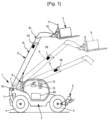
- the handling arm 6 is movable in rotation by a cylinder 8 connected to the chassis 2 and to the handling arm 6.
- the handling arm 6 comprises at least two segments 6 1 and 6 2 deployable using an extension cylinder, not shown, arranged between the at least two segments 6 1 and 6 2 .
- the displacement detectors 18 comprise for example a first sensor located at the axis 7 and arranged to measure the angle of inclination of the handling arm 6.
- the displacement detectors are configured to produce a signal representative of the angle of inclination of the handling arm 6 relative to the chassis 2 according to the data of the first sensor.
- the displacement detectors 18 comprise for example a second sensor located at the extension cylinder and arranged to measure a stroke of said extension cylinder.
- the displacement detectors 18 are configured to produce a signal representative of the extension length of the handling arm 6 according to the data of the second sensor.
- the displacement sensors 18 enable the control unit 10 to determine a lowering movement and/or an extending movement of the handling arm 6.
- the control unit 10 determines a lowering movement of the handling arm 6 in response to a decrease in the tilt angle.
- the control unit 10 determines an extending movement of the handling arm 6 in response to an increase in the extension length of the handling arm 6, for example an increase in the stroke of the extension cylinder.
- the control unit 10 determines the nature of the movement of the handling arm 6. For this, several methods are possible.
- the control unit 10 comprises a processing means configured to determine a signal representative of the rotation speed of the handling arm 6 in the direction of the axis 7. In this embodiment, the control unit 10 determines a lowering movement if the rotation speed is non-zero in the direction of the ground.
- the signal relating to the rotation speed can be determined by measuring a hydraulic flow rate supplying the cylinder 8.
- the signal relating to the rotation speed can be determined as a function of a variation over time of the angle of inclination of the handling arm 6.
- the processing means is configured to determine a signal representative of the extension speed of the handling arm 6.
- the control unit 10 determines an extension movement if the extension speed is non-zero in a direction moving away from the chassis 2.
- the signal relating to the extension speed can be determined by measuring a hydraulic flow rate supplying the extension cylinder.
- the signal relating to the extension speed can be determined as a function of the variation over time of the length of the handling arm 6.
- the handling machine 1 further comprises a tilt detector 11 configured to produce a signal relating to a tilting moment applied to the chassis 2 about a tilting axis, located at the front axle 3.
- Stabilizing feet 5 can optionally be deployed to lift the front axle 3 in which case the stabilizing feet 5 define the tilting axis.
- the tilt sensor 11 is arranged at the rear axle 4.
- the rear axle 4 of the handling machine 1 comprises two wheel support arms 60 carrying rear wheels 62.
- Each wheel support arm 60 comprises an extensometer 61 configured to measure a tensile deformation of said wheel support arm 60 in a direction perpendicular to said arm 60.
- the extensometers 61 are configured to measure a bending deformation of the wheel support arm 60, in particular a length variation between two spaced terminals on the wheel support arm 60.
- the measurement signals of the extensometers 61 may be used to form the signal indicative of the tipping moment, for example as an average of the two measurement signals.
- the rear axle 4 is connected in an oscillating manner to the chassis 2 by means of a pivot 66 with a longitudinal axis passing through a central part 65 of the axle.
- the handling machine 1 further comprises a control unit 10 configured to receive the signals from the tilt detector 11 and the displacement detectors 18 and to slow down, prevent or stop the movement of the handling arm 6 if the signal representative of the tilting moment is greater than an effective threshold.
- the control unit 10 is configured to prevent or stop the movement of the handling arm 6 by reducing or stopping the hydraulic flow supplying the cylinder 8 and/or the extension cylinder.
- the value of the descent threshold is less than the value of the extension threshold, so the descent threshold represents a smaller tipping moment than the moment tilting moment represented by the extension threshold.
- the movement is stopped further from the stability limit, in terms of tilting moment, than for an approach by extending the handling arm 6 without lowering.
- This setting takes into account the fact that the inertial forces implemented when interrupting a lowering movement of the arm have a more influential effect on the stability of the machine than the inertial forces implemented when interrupting an extension movement of the arm.
- the handling machine 1 comprises a display 13 connected to the control unit 10 and configured to display a warning signal if the signal relating to the tipping moment is greater than the effective threshold.
- the handling machine comprises an extension detector 16 of the handling arm 6 configured to determine an extension of the handling arm 6.
- the extension of the handling arm is not expressly measured and the extension sensor is not required.
- the effective threshold can be determined based on the tilt angle of the handling arm without taking into account an extension measurement. Indeed, the increase in the tilting moment of the handling machine without lowering the handling arm can be considered in some cases as an implicit detection that an extension movement of the handling arm is in progress.
- control unit 10 can be configured to implement a control method 200 of the handling machine 1, as shown in the figure 3 .
- the control method 200 serves to slow down, prevent or stop the movement of the handling arm 6 in order to avoid tilting of the handling machine 1.
- control unit 10 is configured to determine the effective threshold by implementing the method 100 shown in FIG. figure 4 .
- step 102 may constitute a step of determining a movement request relating to a lowering or raising of the handling arm 6.
- the movement request may be determined by determining a particular actuation of the actuating member, for example orientation of the actuating member by a user in a predetermined direction.
- step 103 of assigning the lowering threshold to the effective threshold is performed in response to the determination of a request to lower the handling arm and step 104 of assigning the extension threshold to the effective threshold is performed in response to the determination of a request to extend the handling arm 6.
- the descent threshold and the extension threshold are preferably variable depending on whether or not the stabilizing feet 5 are deployed.
- control unit can be implemented in different forms, in a unitary or distributed manner, by means of hardware and/or software components.
- Usable hardware components are specific integrated circuits ASIC, programmable logic networks FPGA or microprocessors.
- Software components can be written in different programming languages, for example C, C++, Java or VHDL. This list is not exhaustive.
Landscapes
- Engineering & Computer Science (AREA)
- Structural Engineering (AREA)
- Transportation (AREA)
- Life Sciences & Earth Sciences (AREA)
- Geology (AREA)
- Mechanical Engineering (AREA)
- Civil Engineering (AREA)
- Forklifts And Lifting Vehicles (AREA)
- Manipulator (AREA)
- Operation Control Of Excavators (AREA)
Claims (8)
- Handhabungsmaschine (1), umfassend:einen Hauptkörper (2),einen teleskopischen Handhabungsarm (6), der auf dem Hauptkörper angebracht und um eine horizontale Rotationsachse (7) rotatorisch beweglich und gemäß einer Längsrichtung des Handhabungsarms ausfahrbar und einziehbar ist, wobei der Handhabungsarm (6) um eine zum Hauptkörper transversale Achse ausrichtbar ist, die sich an einem ersten Ende des Handhabungsarms (6) befindet und der Hauptkörper auf Rädern angebracht ist, die von Achsen getragen werden,Aktuatoren (8), die ausgelegt sind, um den Handhabungsarm aufzurichten und abzusenken und auszufahren und einzuziehen;einen Kippdetektor (11), der ausgelegt ist, um ein Signal auszugeben, das sich auf ein Kippmoment bezieht, das auf den Hauptkörper um eine Kippachse der Handhabungsmaschine angewendet wird;Verlagerungsdetektoren (18) oder Verlagerungsanforderungsdetektoren, die ausgelegt sind, um ein Signal auszugeben, das sich auf Bewegungen oder Bewegungsanforderungen des Handhabungsarms im Verhältnis zum Hauptkörper bezieht; undeine Steuereinheit (10), die ausgelegt ist, um die Signale des Kippdetektors und der Verlagerungsdetektoren oder der Verlagerungsanforderungsdetektoren zu empfangen und um:die Bewegung des Handhabungsarms zu verlangsamen, zu verhindern oder zu stoppen (203), wenn das für das Kippmoment repräsentative Signal über einem effektiven Grenzwert liegt,dem effektiven Grenzwert als Antwort auf eine Bestimmung einer Abwärtsbewegung oder einer Bewegungsanforderung, den Handhabungsarm zu senken, einen Wert eines Abwärtsgrenzwerts zuzuweisen (103);dem effektiven Grenzwert als Antwort auf eine explizite oder implizite Bestimmung einer Streckbewegung oder einer Bewegungsanforderung, den Handhabungsarm zu strecken, einen Wert eines Streckgrenzwerts zuzuweisen (104);und wobei der Wert des Abwärtsgrenzwerts kleiner als der Wert des Streckgrenzwerts ist,dadurch gekennzeichnet, dass der Kippdetektor ein Extensometer umfasst, das im Bereich einer Achse gegenüber einem zweiten Ende des Handhabungsarms (6) eingerichtet ist und wobei das Signal, das sich auf ein Kippmoment bezieht, ein Signal ist, das sich auf eine Verformung der Achse gegenüber dem zweiten Ende des Handhabungsarms (6) bezieht.
- Maschine nach Anspruch 1, wobei die Steuereinheit (10) ausgelegt ist, um dem effektiven Grenzwert als Antwort auf eine Bestimmung einer Abwärts- und Streckbewegung oder einer Bewegungsanforderung, den Handhabungsarm gleichzeitig zu senken und zu strecken, den Wert des Abwärtsgrenzwerts zuzuweisen.
- Maschine nach Anspruch 1 oder 2, wobei der Abwärtsgrenzwert und/oder der Streckgrenzwert vorher festgelegt ist/sind.
- Maschine nach einem der Ansprüche 1 bis 3, wobei die Verlagerungsdetektoren (18) einen Winkelsensor umfassen, der ausgelegt ist, um einen Neigungswinkel des Handhabungsarms (6) im Verhältnis zu einer horizontalen Ebene oder im Verhältnis zum Hauptkörper (2) der Handhabungsmaschine zu messen.
- Maschine nach Anspruch 4, wobei die Steuereinheit (10) ausgelegt ist, um eine Verringerung des vom Winkelsensor gemessenen Neigungswinkels festzustellen und eine Abwärtsbewegung des Handhabungsarms als Antwort auf die Verringerung des Neigungswinkels zu bestimmen.
- Maschine nach einem der Ansprüche 1 bis 5, wobei die Verlagerungsdetektoren (18) einen Längensensor umfassen, der ausgelegt ist, um eine Streckamplitude des Handhabungsarms zu messen.
- Maschine nach Anspruch 6, wobei die Steuereinheit (10) ausgelegt ist, um eine Zunahme der Länge des Handhabungsarms festzustellen und eine Streckbewegung des Handhabungsarms als Antwort auf die Zunahme der Länge des Handhabungsarms zu bestimmen.
- Verfahren zur Steuerung einer Handhabungsmaschine (1), die einen Hauptkörper und einen teleskopischen Handhabungsarm (6) umfasst, der auf dem Hauptkörper (2) angebracht und um eine horizontale Rotationsachse rotatorisch beweglich und gemäß einer Längsrichtung des Handhabungsarms ausfahrbar und einziehbar ist, wobei der Handhabungsarm (6) um eine zum Hauptkörper transversale Achse ausrichtbar ist, die sich an einem ersten Ende des Handhabungsarms (6) befindet und der Hauptkörper auf Rädern angebracht ist, die von Achsen getragen werden, wobei das Verfahren umfasst:Bestimmen (201) eines Signals, das sich auf ein Kippmoment bezieht, das auf den Hauptkörper im Verhältnis zu einer Kippachse der Maschine mit einem Kippdetektor angewendet wird,Bestimmen (102) eines Signals, das sich auf Bewegungen oder Bewegungsanforderungen des Handhabungsarms im Verhältnis zum Hauptkörper bezieht,Verlangsamen, Verhindern oder Stoppen (203) einer Bewegung des Handhabungsarms, wenn das für das Kippmoment repräsentative Signal über einem effektiven Grenzwert liegt,Zuweisen (103), dem effektiven Grenzwert als Antwort auf eine Bestimmung einer Abwärtsbewegung oder einer Bewegungsanforderung, den Handhabungsarm zu senken, eines Werts eines Abwärtsgrenzwerts;Zuweisen (104), dem effektiven Grenzwert als Antwort auf eine explizite oder implizite Bestimmung einer Streckbewegung des Handhabungsarms, eines Werts eines Streckgrenzwerts;und wobei der Wert des Abwärtsgrenzwerts kleiner als der Wert des Streckgrenzwerts ist,dadurch gekennzeichnet, dass der Kippdetektor ein Extensometer umfasst, das im Bereich einer Achse gegenüber einem zweiten Ende des Handhabungsarms (6) eingerichtet ist und wobei das Signal, das sich auf ein Kippmoment bezieht, ein Signal ist, das sich auf eine Verformung der Achse gegenüber dem zweiten Ende des Handhabungsarms (6) bezieht.
Priority Applications (7)
| Application Number | Priority Date | Filing Date | Title |
|---|---|---|---|
| EP19305597.7A EP3736245B2 (de) | 2019-05-10 | 2019-05-10 | Steuerung einer fördermaschine |
| BR112021020540A BR112021020540A2 (pt) | 2019-05-10 | 2020-05-07 | Controle de uma máquina de manuseio |
| CA3132516A CA3132516C (fr) | 2019-05-10 | 2020-05-07 | Commande d'une machine de manutention |
| PCT/EP2020/062685 WO2020229291A1 (fr) | 2019-05-10 | 2020-05-07 | Commande d'une machine de manutention |
| AU2020273720A AU2020273720B2 (en) | 2019-05-10 | 2020-05-07 | Control of a handling machine |
| CN202080034345.2A CN113795454B (zh) | 2019-05-10 | 2020-05-07 | 装卸机的控制 |
| US17/606,878 US12071331B2 (en) | 2019-05-10 | 2020-05-07 | Control of a handling machine |
Applications Claiming Priority (1)
| Application Number | Priority Date | Filing Date | Title |
|---|---|---|---|
| EP19305597.7A EP3736245B2 (de) | 2019-05-10 | 2019-05-10 | Steuerung einer fördermaschine |
Publications (3)
| Publication Number | Publication Date |
|---|---|
| EP3736245A1 EP3736245A1 (de) | 2020-11-11 |
| EP3736245B1 EP3736245B1 (de) | 2021-12-15 |
| EP3736245B2 true EP3736245B2 (de) | 2025-02-26 |
Family
ID=66685505
Family Applications (1)
| Application Number | Title | Priority Date | Filing Date |
|---|---|---|---|
| EP19305597.7A Active EP3736245B2 (de) | 2019-05-10 | 2019-05-10 | Steuerung einer fördermaschine |
Country Status (6)
| Country | Link |
|---|---|
| US (1) | US12071331B2 (de) |
| EP (1) | EP3736245B2 (de) |
| CN (1) | CN113795454B (de) |
| AU (1) | AU2020273720B2 (de) |
| BR (1) | BR112021020540A2 (de) |
| WO (1) | WO2020229291A1 (de) |
Families Citing this family (4)
| Publication number | Priority date | Publication date | Assignee | Title |
|---|---|---|---|---|
| EP3736245B2 (de) | 2019-05-10 | 2025-02-26 | Manitou Bf | Steuerung einer fördermaschine |
| CA3137460C (fr) * | 2019-06-07 | 2025-01-21 | Manitou Bf | Engin de manutention de charge et procede de commande d'un engin de manutention de charge |
| CA3171550A1 (en) | 2021-09-06 | 2023-03-06 | Manitou Italia S.R.L. | Telehandler with improved winch |
| FR3130779B1 (fr) * | 2021-12-20 | 2023-11-03 | Manitou Bf | Machine de manutention comportant un bras de levage équipé d’un outil articulé et procédé de commande d’une telle machine de manutention |
Family Cites Families (6)
| Publication number | Priority date | Publication date | Assignee | Title |
|---|---|---|---|---|
| JP3252006B2 (ja) | 1993-03-10 | 2002-01-28 | 株式会社タダノ | ブーム付き作業車の制御装置 |
| GB2390595B (en) | 2002-07-12 | 2005-08-24 | Bamford Excavators Ltd | Control system for a machine |
| GB2483647B (en) | 2010-09-14 | 2014-04-09 | Bamford Excavators Ltd | A machine, controller, and control method |
| CA2815333C (en) * | 2010-11-12 | 2015-05-19 | Jlg Industries, Inc. | Longitudinal stability monitoring system |
| ITTO20110399A1 (it) * | 2011-05-06 | 2012-11-07 | Merlo Project Srl | Veicolo sollevatore |
| EP3736245B2 (de) | 2019-05-10 | 2025-02-26 | Manitou Bf | Steuerung einer fördermaschine |
-
2019
- 2019-05-10 EP EP19305597.7A patent/EP3736245B2/de active Active
-
2020
- 2020-05-07 CN CN202080034345.2A patent/CN113795454B/zh active Active
- 2020-05-07 BR BR112021020540A patent/BR112021020540A2/pt active IP Right Grant
- 2020-05-07 WO PCT/EP2020/062685 patent/WO2020229291A1/fr not_active Ceased
- 2020-05-07 US US17/606,878 patent/US12071331B2/en active Active
- 2020-05-07 AU AU2020273720A patent/AU2020273720B2/en active Active
Also Published As
| Publication number | Publication date |
|---|---|
| BR112021020540A2 (pt) | 2022-01-04 |
| EP3736245B1 (de) | 2021-12-15 |
| CN113795454B (zh) | 2023-04-11 |
| CN113795454A (zh) | 2021-12-14 |
| US20220204324A1 (en) | 2022-06-30 |
| US12071331B2 (en) | 2024-08-27 |
| AU2020273720B2 (en) | 2025-10-09 |
| EP3736245A1 (de) | 2020-11-11 |
| AU2020273720A1 (en) | 2021-11-04 |
| CA3132516A1 (fr) | 2020-11-19 |
| WO2020229291A1 (fr) | 2020-11-19 |
Similar Documents
| Publication | Publication Date | Title |
|---|---|---|
| EP3736245B2 (de) | Steuerung einer fördermaschine | |
| EP3792213B1 (de) | Pendelachse für eine hubmaschine, eine solche achse umfassende hubmaschine und steuerungsverfahren | |
| EP2301884B1 (de) | Hubarbeitsbühne und Verfahren für die Steuerung dessen | |
| FR2691185A1 (fr) | Système de commande pour prévenir automatiquement la surcharge d'une excavatrice. | |
| FR2792924A1 (fr) | Chariot de manutention au sol | |
| EP4466216A1 (de) | Maschinenstabilitätsdetektion und -anzeige für mobile hebeausrüstung | |
| CN111348562A (zh) | 移动式起重机 | |
| EP3431435B1 (de) | Steuerung einer fördermaschine | |
| EP1879827B1 (de) | Schlingenvorrichtung für ein teil mit kraftausgleich und diese umfassendes hubsystem | |
| FR2801876A1 (fr) | Extension de fleche et commande d'angle de fleche pour une machine | |
| CA3132516C (fr) | Commande d'une machine de manutention | |
| EP1923347A1 (de) | Hebebühne und Verfahren zur Steuerung einer solchen Hebebühne | |
| EP1186568B1 (de) | Hubarbeitsbühne und Verfahren zum Steuern einer sich darauf befindenden Last | |
| RU2799286C2 (ru) | Управление погрузочно-разгрузочной машиной | |
| EP4464649A1 (de) | Armhandhabungsmaschine und steuerungsverfahren dafür | |
| EP4452822B1 (de) | Handhabungsmaschine mit einem hubarm mit gelenkwerkzeug und verfahren zur steuerung einer derartigen handhabungsmaschine | |
| EP4464642A1 (de) | Geschwindigkeitssteuerung einer handhabungsmaschine | |
| EP3292071B1 (de) | Verfahren und vorrichtung zur überwachung einer stütze für einen wagen mit einer stabilisationsvorrichtung | |
| WO1991007310A1 (fr) | Treuil pour remorquage d'objets immerges | |
| WO2025036898A1 (fr) | Méthode d'alerte pour une nacelle élévatrice, notamment une nacelle articulée, et nacelle élévatrice associée | |
| FR2908120A1 (fr) | Nacelle elevatrice et procede de surveillance d'une telle nacelle a l'arret |
Legal Events
| Date | Code | Title | Description |
|---|---|---|---|
| PUAI | Public reference made under article 153(3) epc to a published international application that has entered the european phase |
Free format text: ORIGINAL CODE: 0009012 |
|
| STAA | Information on the status of an ep patent application or granted ep patent |
Free format text: STATUS: THE APPLICATION HAS BEEN PUBLISHED |
|
| AK | Designated contracting states |
Kind code of ref document: A1 Designated state(s): AL AT BE BG CH CY CZ DE DK EE ES FI FR GB GR HR HU IE IS IT LI LT LU LV MC MK MT NL NO PL PT RO RS SE SI SK SM TR |
|
| AX | Request for extension of the european patent |
Extension state: BA ME |
|
| STAA | Information on the status of an ep patent application or granted ep patent |
Free format text: STATUS: REQUEST FOR EXAMINATION WAS MADE |
|
| 17P | Request for examination filed |
Effective date: 20210105 |
|
| RBV | Designated contracting states (corrected) |
Designated state(s): AL AT BE BG CH CY CZ DE DK EE ES FI FR GB GR HR HU IE IS IT LI LT LU LV MC MK MT NL NO PL PT RO RS SE SI SK SM TR |
|
| GRAP | Despatch of communication of intention to grant a patent |
Free format text: ORIGINAL CODE: EPIDOSNIGR1 |
|
| STAA | Information on the status of an ep patent application or granted ep patent |
Free format text: STATUS: GRANT OF PATENT IS INTENDED |
|
| INTG | Intention to grant announced |
Effective date: 20210623 |
|
| GRAJ | Information related to disapproval of communication of intention to grant by the applicant or resumption of examination proceedings by the epo deleted |
Free format text: ORIGINAL CODE: EPIDOSDIGR1 |
|
| STAA | Information on the status of an ep patent application or granted ep patent |
Free format text: STATUS: REQUEST FOR EXAMINATION WAS MADE |
|
| INTC | Intention to grant announced (deleted) | ||
| GRAP | Despatch of communication of intention to grant a patent |
Free format text: ORIGINAL CODE: EPIDOSNIGR1 |
|
| STAA | Information on the status of an ep patent application or granted ep patent |
Free format text: STATUS: GRANT OF PATENT IS INTENDED |
|
| INTG | Intention to grant announced |
Effective date: 20211007 |
|
| GRAS | Grant fee paid |
Free format text: ORIGINAL CODE: EPIDOSNIGR3 |
|
| GRAA | (expected) grant |
Free format text: ORIGINAL CODE: 0009210 |
|
| STAA | Information on the status of an ep patent application or granted ep patent |
Free format text: STATUS: THE PATENT HAS BEEN GRANTED |
|
| AK | Designated contracting states |
Kind code of ref document: B1 Designated state(s): AL AT BE BG CH CY CZ DE DK EE ES FI FR GB GR HR HU IE IS IT LI LT LU LV MC MK MT NL NO PL PT RO RS SE SI SK SM TR |
|
| REG | Reference to a national code |
Ref country code: GB Ref legal event code: FG4D Free format text: NOT ENGLISH Ref country code: CH Ref legal event code: EP |
|
| REG | Reference to a national code |
Ref country code: DE Ref legal event code: R096 Ref document number: 602019010084 Country of ref document: DE |
|
| REG | Reference to a national code |
Ref country code: IE Ref legal event code: FG4D Free format text: LANGUAGE OF EP DOCUMENT: FRENCH |
|
| REG | Reference to a national code |
Ref country code: AT Ref legal event code: REF Ref document number: 1455366 Country of ref document: AT Kind code of ref document: T Effective date: 20220115 |
|
| REG | Reference to a national code |
Ref country code: NL Ref legal event code: FP |
|
| REG | Reference to a national code |
Ref country code: LT Ref legal event code: MG9D |
|
| PG25 | Lapsed in a contracting state [announced via postgrant information from national office to epo] |
Ref country code: RS Free format text: LAPSE BECAUSE OF FAILURE TO SUBMIT A TRANSLATION OF THE DESCRIPTION OR TO PAY THE FEE WITHIN THE PRESCRIBED TIME-LIMIT Effective date: 20211215 Ref country code: LT Free format text: LAPSE BECAUSE OF FAILURE TO SUBMIT A TRANSLATION OF THE DESCRIPTION OR TO PAY THE FEE WITHIN THE PRESCRIBED TIME-LIMIT Effective date: 20211215 Ref country code: FI Free format text: LAPSE BECAUSE OF FAILURE TO SUBMIT A TRANSLATION OF THE DESCRIPTION OR TO PAY THE FEE WITHIN THE PRESCRIBED TIME-LIMIT Effective date: 20211215 Ref country code: BG Free format text: LAPSE BECAUSE OF FAILURE TO SUBMIT A TRANSLATION OF THE DESCRIPTION OR TO PAY THE FEE WITHIN THE PRESCRIBED TIME-LIMIT Effective date: 20220315 |
|
| REG | Reference to a national code |
Ref country code: AT Ref legal event code: MK05 Ref document number: 1455366 Country of ref document: AT Kind code of ref document: T Effective date: 20211215 |
|
| PG25 | Lapsed in a contracting state [announced via postgrant information from national office to epo] |
Ref country code: SE Free format text: LAPSE BECAUSE OF FAILURE TO SUBMIT A TRANSLATION OF THE DESCRIPTION OR TO PAY THE FEE WITHIN THE PRESCRIBED TIME-LIMIT Effective date: 20211215 Ref country code: NO Free format text: LAPSE BECAUSE OF FAILURE TO SUBMIT A TRANSLATION OF THE DESCRIPTION OR TO PAY THE FEE WITHIN THE PRESCRIBED TIME-LIMIT Effective date: 20220315 Ref country code: LV Free format text: LAPSE BECAUSE OF FAILURE TO SUBMIT A TRANSLATION OF THE DESCRIPTION OR TO PAY THE FEE WITHIN THE PRESCRIBED TIME-LIMIT Effective date: 20211215 Ref country code: HR Free format text: LAPSE BECAUSE OF FAILURE TO SUBMIT A TRANSLATION OF THE DESCRIPTION OR TO PAY THE FEE WITHIN THE PRESCRIBED TIME-LIMIT Effective date: 20211215 Ref country code: GR Free format text: LAPSE BECAUSE OF FAILURE TO SUBMIT A TRANSLATION OF THE DESCRIPTION OR TO PAY THE FEE WITHIN THE PRESCRIBED TIME-LIMIT Effective date: 20220316 |
|
| PG25 | Lapsed in a contracting state [announced via postgrant information from national office to epo] |
Ref country code: SM Free format text: LAPSE BECAUSE OF FAILURE TO SUBMIT A TRANSLATION OF THE DESCRIPTION OR TO PAY THE FEE WITHIN THE PRESCRIBED TIME-LIMIT Effective date: 20211215 Ref country code: SK Free format text: LAPSE BECAUSE OF FAILURE TO SUBMIT A TRANSLATION OF THE DESCRIPTION OR TO PAY THE FEE WITHIN THE PRESCRIBED TIME-LIMIT Effective date: 20211215 Ref country code: RO Free format text: LAPSE BECAUSE OF FAILURE TO SUBMIT A TRANSLATION OF THE DESCRIPTION OR TO PAY THE FEE WITHIN THE PRESCRIBED TIME-LIMIT Effective date: 20211215 Ref country code: PT Free format text: LAPSE BECAUSE OF FAILURE TO SUBMIT A TRANSLATION OF THE DESCRIPTION OR TO PAY THE FEE WITHIN THE PRESCRIBED TIME-LIMIT Effective date: 20220418 Ref country code: ES Free format text: LAPSE BECAUSE OF FAILURE TO SUBMIT A TRANSLATION OF THE DESCRIPTION OR TO PAY THE FEE WITHIN THE PRESCRIBED TIME-LIMIT Effective date: 20211215 Ref country code: EE Free format text: LAPSE BECAUSE OF FAILURE TO SUBMIT A TRANSLATION OF THE DESCRIPTION OR TO PAY THE FEE WITHIN THE PRESCRIBED TIME-LIMIT Effective date: 20211215 Ref country code: CZ Free format text: LAPSE BECAUSE OF FAILURE TO SUBMIT A TRANSLATION OF THE DESCRIPTION OR TO PAY THE FEE WITHIN THE PRESCRIBED TIME-LIMIT Effective date: 20211215 |
|
| PG25 | Lapsed in a contracting state [announced via postgrant information from national office to epo] |
Ref country code: PL Free format text: LAPSE BECAUSE OF FAILURE TO SUBMIT A TRANSLATION OF THE DESCRIPTION OR TO PAY THE FEE WITHIN THE PRESCRIBED TIME-LIMIT Effective date: 20211215 Ref country code: AT Free format text: LAPSE BECAUSE OF FAILURE TO SUBMIT A TRANSLATION OF THE DESCRIPTION OR TO PAY THE FEE WITHIN THE PRESCRIBED TIME-LIMIT Effective date: 20211215 |
|
| REG | Reference to a national code |
Ref country code: DE Ref legal event code: R026 Ref document number: 602019010084 Country of ref document: DE |
|
| PLBI | Opposition filed |
Free format text: ORIGINAL CODE: 0009260 |
|
| PLAX | Notice of opposition and request to file observation + time limit sent |
Free format text: ORIGINAL CODE: EPIDOSNOBS2 |
|
| PG25 | Lapsed in a contracting state [announced via postgrant information from national office to epo] |
Ref country code: IS Free format text: LAPSE BECAUSE OF FAILURE TO SUBMIT A TRANSLATION OF THE DESCRIPTION OR TO PAY THE FEE WITHIN THE PRESCRIBED TIME-LIMIT Effective date: 20220415 |
|
| 26 | Opposition filed |
Opponent name: J.C. BAMFORD EXCAVATORS LIMITED Effective date: 20220915 |
|
| PG25 | Lapsed in a contracting state [announced via postgrant information from national office to epo] |
Ref country code: DK Free format text: LAPSE BECAUSE OF FAILURE TO SUBMIT A TRANSLATION OF THE DESCRIPTION OR TO PAY THE FEE WITHIN THE PRESCRIBED TIME-LIMIT Effective date: 20211215 Ref country code: AL Free format text: LAPSE BECAUSE OF FAILURE TO SUBMIT A TRANSLATION OF THE DESCRIPTION OR TO PAY THE FEE WITHIN THE PRESCRIBED TIME-LIMIT Effective date: 20211215 |
|
| PG25 | Lapsed in a contracting state [announced via postgrant information from national office to epo] |
Ref country code: SI Free format text: LAPSE BECAUSE OF FAILURE TO SUBMIT A TRANSLATION OF THE DESCRIPTION OR TO PAY THE FEE WITHIN THE PRESCRIBED TIME-LIMIT Effective date: 20211215 |
|
| REG | Reference to a national code |
Ref country code: CH Ref legal event code: PL |
|
| PG25 | Lapsed in a contracting state [announced via postgrant information from national office to epo] |
Ref country code: MC Free format text: LAPSE BECAUSE OF FAILURE TO SUBMIT A TRANSLATION OF THE DESCRIPTION OR TO PAY THE FEE WITHIN THE PRESCRIBED TIME-LIMIT Effective date: 20211215 Ref country code: LU Free format text: LAPSE BECAUSE OF NON-PAYMENT OF DUE FEES Effective date: 20220510 Ref country code: LI Free format text: LAPSE BECAUSE OF NON-PAYMENT OF DUE FEES Effective date: 20220531 Ref country code: CH Free format text: LAPSE BECAUSE OF NON-PAYMENT OF DUE FEES Effective date: 20220531 |
|
| PLBB | Reply of patent proprietor to notice(s) of opposition received |
Free format text: ORIGINAL CODE: EPIDOSNOBS3 |
|
| PG25 | Lapsed in a contracting state [announced via postgrant information from national office to epo] |
Ref country code: IE Free format text: LAPSE BECAUSE OF NON-PAYMENT OF DUE FEES Effective date: 20220510 |
|
| P01 | Opt-out of the competence of the unified patent court (upc) registered |
Effective date: 20230530 |
|
| PLBP | Opposition withdrawn |
Free format text: ORIGINAL CODE: 0009264 |
|
| PG25 | Lapsed in a contracting state [announced via postgrant information from national office to epo] |
Ref country code: MK Free format text: LAPSE BECAUSE OF FAILURE TO SUBMIT A TRANSLATION OF THE DESCRIPTION OR TO PAY THE FEE WITHIN THE PRESCRIBED TIME-LIMIT Effective date: 20211215 Ref country code: CY Free format text: LAPSE BECAUSE OF FAILURE TO SUBMIT A TRANSLATION OF THE DESCRIPTION OR TO PAY THE FEE WITHIN THE PRESCRIBED TIME-LIMIT Effective date: 20211215 |
|
| PG25 | Lapsed in a contracting state [announced via postgrant information from national office to epo] |
Ref country code: HU Free format text: LAPSE BECAUSE OF FAILURE TO SUBMIT A TRANSLATION OF THE DESCRIPTION OR TO PAY THE FEE WITHIN THE PRESCRIBED TIME-LIMIT; INVALID AB INITIO Effective date: 20190510 |
|
| PG25 | Lapsed in a contracting state [announced via postgrant information from national office to epo] |
Ref country code: TR Free format text: LAPSE BECAUSE OF FAILURE TO SUBMIT A TRANSLATION OF THE DESCRIPTION OR TO PAY THE FEE WITHIN THE PRESCRIBED TIME-LIMIT Effective date: 20211215 |
|
| PG25 | Lapsed in a contracting state [announced via postgrant information from national office to epo] |
Ref country code: MT Free format text: LAPSE BECAUSE OF FAILURE TO SUBMIT A TRANSLATION OF THE DESCRIPTION OR TO PAY THE FEE WITHIN THE PRESCRIBED TIME-LIMIT Effective date: 20211215 |
|
| PUAH | Patent maintained in amended form |
Free format text: ORIGINAL CODE: 0009272 |
|
| STAA | Information on the status of an ep patent application or granted ep patent |
Free format text: STATUS: PATENT MAINTAINED AS AMENDED |
|
| 27A | Patent maintained in amended form |
Effective date: 20250226 |
|
| AK | Designated contracting states |
Kind code of ref document: B2 Designated state(s): AL AT BE BG CH CY CZ DE DK EE ES FI FR GB GR HR HU IE IS IT LI LT LU LV MC MK MT NL NO PL PT RO RS SE SI SK SM TR |
|
| REG | Reference to a national code |
Ref country code: DE Ref legal event code: R102 Ref document number: 602019010084 Country of ref document: DE |
|
| PGFP | Annual fee paid to national office [announced via postgrant information from national office to epo] |
Ref country code: NL Payment date: 20250429 Year of fee payment: 7 |
|
| REG | Reference to a national code |
Ref country code: NL Ref legal event code: FP |
|
| PGFP | Annual fee paid to national office [announced via postgrant information from national office to epo] |
Ref country code: DE Payment date: 20250513 Year of fee payment: 7 |
|
| PGFP | Annual fee paid to national office [announced via postgrant information from national office to epo] |
Ref country code: GB Payment date: 20250521 Year of fee payment: 7 |
|
| PGFP | Annual fee paid to national office [announced via postgrant information from national office to epo] |
Ref country code: BE Payment date: 20250527 Year of fee payment: 7 Ref country code: IT Payment date: 20250508 Year of fee payment: 7 |
|
| PGFP | Annual fee paid to national office [announced via postgrant information from national office to epo] |
Ref country code: FR Payment date: 20250530 Year of fee payment: 7 |