EP3735869B1 - Schwenktürsystem und gefriervorrichtung - Google Patents
Schwenktürsystem und gefriervorrichtung Download PDFInfo
- Publication number
- EP3735869B1 EP3735869B1 EP20174914.0A EP20174914A EP3735869B1 EP 3735869 B1 EP3735869 B1 EP 3735869B1 EP 20174914 A EP20174914 A EP 20174914A EP 3735869 B1 EP3735869 B1 EP 3735869B1
- Authority
- EP
- European Patent Office
- Prior art keywords
- mullion
- swing
- swing doors
- doors
- door system
- Prior art date
- Legal status (The legal status is an assumption and is not a legal conclusion. Google has not performed a legal analysis and makes no representation as to the accuracy of the status listed.)
- Active
Links
Images





Classifications
-
- E—FIXED CONSTRUCTIONS
- E05—LOCKS; KEYS; WINDOW OR DOOR FITTINGS; SAFES
- E05D—HINGES OR SUSPENSION DEVICES FOR DOORS, WINDOWS OR WINGS
- E05D7/00—Hinges or pivots of special construction
- E05D7/08—Hinges or pivots of special construction for use in suspensions comprising two spigots placed at opposite edges of the wing, especially at the top and the bottom, e.g. trunnions
- E05D7/081—Hinges or pivots of special construction for use in suspensions comprising two spigots placed at opposite edges of the wing, especially at the top and the bottom, e.g. trunnions the pivot axis of the wing being situated near one edge of the wing, especially at the top and bottom, e.g. trunnions
-
- A—HUMAN NECESSITIES
- A47—FURNITURE; DOMESTIC ARTICLES OR APPLIANCES; COFFEE MILLS; SPICE MILLS; SUCTION CLEANERS IN GENERAL
- A47F—SPECIAL FURNITURE, FITTINGS, OR ACCESSORIES FOR SHOPS, STOREHOUSES, BARS, RESTAURANTS OR THE LIKE; PAYING COUNTERS
- A47F3/00—Show cases or show cabinets
- A47F3/04—Show cases or show cabinets air-conditioned, refrigerated
- A47F3/0404—Cases or cabinets of the closed type
- A47F3/0426—Details
- A47F3/043—Doors, covers
-
- A—HUMAN NECESSITIES
- A47—FURNITURE; DOMESTIC ARTICLES OR APPLIANCES; COFFEE MILLS; SPICE MILLS; SUCTION CLEANERS IN GENERAL
- A47F—SPECIAL FURNITURE, FITTINGS, OR ACCESSORIES FOR SHOPS, STOREHOUSES, BARS, RESTAURANTS OR THE LIKE; PAYING COUNTERS
- A47F3/00—Show cases or show cabinets
- A47F3/04—Show cases or show cabinets air-conditioned, refrigerated
- A47F3/0404—Cases or cabinets of the closed type
- A47F3/0426—Details
- A47F3/0434—Glass or transparent panels
-
- E—FIXED CONSTRUCTIONS
- E05—LOCKS; KEYS; WINDOW OR DOOR FITTINGS; SAFES
- E05F—DEVICES FOR MOVING WINGS INTO OPEN OR CLOSED POSITION; CHECKS FOR WINGS; WING FITTINGS NOT OTHERWISE PROVIDED FOR, CONCERNED WITH THE FUNCTIONING OF THE WING
- E05F1/00—Closers or openers for wings, not otherwise provided for in this subclass
- E05F1/02—Closers or openers for wings, not otherwise provided for in this subclass gravity-actuated, e.g. by use of counterweights
- E05F1/04—Closers or openers for wings, not otherwise provided for in this subclass gravity-actuated, e.g. by use of counterweights for wings which lift during movement, operated by their own weight
- E05F1/06—Mechanisms in the shape of hinges or pivots, operated by the weight of the wing
-
- F—MECHANICAL ENGINEERING; LIGHTING; HEATING; WEAPONS; BLASTING
- F25—REFRIGERATION OR COOLING; COMBINED HEATING AND REFRIGERATION SYSTEMS; HEAT PUMP SYSTEMS; MANUFACTURE OR STORAGE OF ICE; LIQUEFACTION SOLIDIFICATION OF GASES
- F25D—REFRIGERATORS; COLD ROOMS; ICE-BOXES; COOLING OR FREEZING APPARATUS NOT OTHERWISE PROVIDED FOR
- F25D23/00—General constructional features
- F25D23/02—Doors; Covers
-
- E—FIXED CONSTRUCTIONS
- E05—LOCKS; KEYS; WINDOW OR DOOR FITTINGS; SAFES
- E05Y—INDEXING SCHEME ASSOCIATED WITH SUBCLASSES E05D AND E05F, RELATING TO CONSTRUCTION ELEMENTS, ELECTRIC CONTROL, POWER SUPPLY, POWER SIGNAL OR TRANSMISSION, USER INTERFACES, MOUNTING OR COUPLING, DETAILS, ACCESSORIES, AUXILIARY OPERATIONS NOT OTHERWISE PROVIDED FOR, APPLICATION THEREOF
- E05Y2900/00—Application of doors, windows, wings or fittings thereof
- E05Y2900/30—Application of doors, windows, wings or fittings thereof for domestic appliances
- E05Y2900/306—Application of doors, windows, wings or fittings thereof for domestic appliances for freezers
-
- E—FIXED CONSTRUCTIONS
- E05—LOCKS; KEYS; WINDOW OR DOOR FITTINGS; SAFES
- E05Y—INDEXING SCHEME ASSOCIATED WITH SUBCLASSES E05D AND E05F, RELATING TO CONSTRUCTION ELEMENTS, ELECTRIC CONTROL, POWER SUPPLY, POWER SIGNAL OR TRANSMISSION, USER INTERFACES, MOUNTING OR COUPLING, DETAILS, ACCESSORIES, AUXILIARY OPERATIONS NOT OTHERWISE PROVIDED FOR, APPLICATION THEREOF
- E05Y2900/00—Application of doors, windows, wings or fittings thereof
- E05Y2900/30—Application of doors, windows, wings or fittings thereof for domestic appliances
- E05Y2900/31—Application of doors, windows, wings or fittings thereof for domestic appliances for refrigerators
-
- F—MECHANICAL ENGINEERING; LIGHTING; HEATING; WEAPONS; BLASTING
- F25—REFRIGERATION OR COOLING; COMBINED HEATING AND REFRIGERATION SYSTEMS; HEAT PUMP SYSTEMS; MANUFACTURE OR STORAGE OF ICE; LIQUEFACTION SOLIDIFICATION OF GASES
- F25D—REFRIGERATORS; COLD ROOMS; ICE-BOXES; COOLING OR FREEZING APPARATUS NOT OTHERWISE PROVIDED FOR
- F25D23/00—General constructional features
- F25D23/02—Doors; Covers
- F25D23/028—Details
Definitions
- the present invention relates to a swing door system for use with a freezer device, comprising two adjacent swing doors and at least one mullion being in contact with said swing doors, wherein each swing door comprises a transparent pane and a non-transparent area, wherein each non-transparent area is proximal to the mullion when the swing doors are in a closed position, and wherein the non-transparent areas and the mullion define a non-transparent region.
- the present invention relates to a freezer device comprising at least one swing door system.
- Freezer devices are used for example in supermarkets and other stores for presenting frozen goods.
- Conventional frames and doors for freezer devices typically comprise robust and large profile structures. These structures block the view of the consumers during their shopping journey onto the presented goods in the freezer device.
- conventional freezer devices comprise very large profile structures since the inner of the cabinet has to be cooled down such that frozen products, for example vegetables, frozen meat, frozen pizza etc. can be kept inside the freezer.
- frozen products for example vegetables, frozen meat, frozen pizza etc.
- these freezers comprise insulating and therefore bulky doors.
- a known swing door system is disclosed in US 2011/043089 A1 .
- Embodiments of the present invention therefore address the problem of improving and further developing a swing door system and a freezer device such that an increased product visibility is achieved in particular when a person is accessing the device and is standing in front of the device.
- the present invention provides a swing door system for use with a freezer device, comprising two adjacent swing doors and at least one mullion being in contact with said swing doors, wherein each swing door comprises a transparent pane and a non-transparent area, wherein each non-transparent area is proximal to the mullion when the swing doors are in a closed position, and wherein the non-transparent areas and the mullion define a non-transparent region, and wherein under an horizontal viewing angle between 0° and 180° with respect to the plane in which the swing doors are arranged when the swing doors are in the closed position all of the horizontal diameters of the non-transparent region are less than 100 mm, preferably less than 80 mm, more preferably less than 70 mm, most preferably less than 60 mm, preferably in any given height, i.e. over the whole vertical height of the transparent panes.
- the present invention provides a freezer device comprising at least one swing door system according to one of the claims 1 to 15, being arranged in a cabinet, such that the opening direction of the swing door system is horizontal.
- the swing door system according to claim 1 is preferably arranged such that the opening direction of the swing door system is horizontal.
- the term "freezer device” refers to a device in which the temperature of the foodstuff is typically kept between -12°C and -30 °C on normal conditions of use. Normal conditions are defined as operating conditions which exist when the cabinet, including all permanently located accessories, has been set up and situated in accordance with the recommendations of the manufacturer and is in service. Typical examples for such foodstuff are the products which are stored according to EN23953, part 2 (September 2012) in the temperature classes L1, L2 and L3.
- mullion refers to a vertical profile attached to the mounting frame of a freezer device where two adjacent doors in a freezer device meet.
- mullions have been used to create a central support surface against which the doors can rest in a sealed fashion when the doors are in a closed position.
- vertical side refers to a vertical profile of the mounting frame at the outer positions of a freezer cabinet (typically left or right).
- horizontal profile refers to the horizontal profile of the mounting frame of a freezer device. Typically, one upper horizontal profile and one lower horizontal profile is provided.
- mounting frame refers to a support structure having upper and lower horizontal profiles, left and right vertical sides. At least a pair of reversible doors can be swingably mounted in the mounting frame in selective left- and right-hand opening directions.
- the horizontal profiles of one device can be arranged in a line of profiles.
- mullion and/or a vertical side and/or a horizontal profile can be incorporated into a cabinet structure of a freezer device.
- non-transparent refers to a region, area or the like in which the view on the goods, products or the like inside the freezer device is obstructed or blocked by one or more opaque elements of the freezer device, for example by spacers, profiles, gaskets, a mullion or by the swing doors.
- a person's viewing direction comprises a vertical part and a horizontal part. Therefore, the term "horizontal viewing angle” is defined by the angle between the projection of the viewing direction into a horizontal plane and the plane in which the swing doors are arranged when the swing doors are in a closed position. Furthermore, the plane in which the swing doors are arranged when the swing doors are in a closed position refers to the surface of the transparent pane outside of the freezer device.
- horizontal diameter refers to a length measured in the horizontal plane in a given height. Therefore, the horizontal diameter of the non-transparent region in a given height depends on the horizontal viewing angle and describes the length of the region in which the view onto the products is blocked.
- width refers to a horizontal length measured in the plane in which the swing doors are arranged when the swing doors are in the closed position. Therefore, the width of the non-transparent region corresponds to the horizontal diameter under a viewing angle of 90° with respect to the plane in which the swing doors being arranged when the swing doors are in a closed position.
- depth refers to a length measured in the plane being perpendicular to the plane in which the swing doors are arranged when the swing doors are in the closed position. Therefore, the depth of the non-transparent region corresponds to the horizontal diameter under a viewing angle of 0° or 180° with respect to the plane in which the swing doors being arranged when the swing doors are in a closed position.
- vertical refers to the direction aligned with the direction of the force of gravity, up or down, as materialized with a plumb line.
- At least one of the horizontal diameters of the non-transparent region is less than 80 mm, preferably less than 70 mm, more preferably less than 50 mm, most preferably less than 45 mm.
- the ratio between the largest horizontal diameter of the non-transparent region and the smallest horizontal diameter of the non-transparent region is less than 2, preferably less than 1.5, more preferably less than 1.2. Thereby the non-transparent region is further minimized.
- the width of said non-transparent region is less than 70 mm, preferably less than 60 mm, more preferably less than 50 mm, most preferably less than 45 mm. This has the advantage that the visibility of the products is improved when a customer is viewing under a viewing angle of approximately 90° into the freezer device.
- the width of the non-transparent region ranging from 25 mm to 60 mm, preferably from 25 mm to 50 mm, most preferably from 25 mm to 40 mm.
- a respectively dimensioned non-transparent region improves the visibility during the selection phase, i.e. when the customer stands in front of the closed swing doors.
- a further advantage is that a stable and mechanically reliable structure of the device is provided.
- the depth of the non-transparent region is less than 70 mm, preferably less than 60 mm, more preferably less than 50 mm, most preferably less than 45 mm.
- the depth of the non-transparent region is preferably ranging from 25 mm to 60 mm, more preferably ranging from 25 mm to 50 mm, most preferably from 25 mm to 40 mm.
- a cross-section of the mullion is T-shaped or Y-shaped or triangle-shaped.
- a T-shaped mullion has the advantage of providing a very solid structure.
- a Y-shaped mullion has the further advantage that cabling or light fixtures can be hidden behind the mullion so that the view of a customer is not distracted by the cabling.
- a triangle-shaped mullion provides enhanced flexibility, e.g. it can serve as a cable duct.
- a part of the mullion reaches in between the two adjacent swing doors, when the swing doors are in the closed position.
- a further advantage is that the depth of the swing door system is minimized, when the mullion reaches between the adjacent swing doors.
- a mullion has the shape of a cuboid profile that comprises a cavity. These mullions achieve the necessary bending stiffness due to their large width and depth.
- a mullion that reaches in between the adjacent swing doors and/or has a T-shape achieves its bending stiffness due to its special design and therefore its width and depth can be smaller compared to cuboid state of the art mullions.
- an insulation profile is attached to the mullion, wherein the insulation profile is attached to the mullion form-fit and/or force-fit, or the insulation profile is firmly bonded to the mullion.
- An advantage of the insulation profile is that it insulates the mullion against the inside of a freezer device. Furthermore, the insulation profile serves to mechanical stabilize the mullion.
- the insulation profile is attached to the mullion form-fit and/or force-fit at least at different fixation points. For example, it is possible to attach the insulation profile at different fixation points via screws and/or rivets and/or other fixation elements to the mullion.
- the fixation points can be arranged, preferably equidistant, at least over 80% of the height of the mullion.
- the insulation profile can be attached with an adhesive and/or an adhesive tape and/or via welding and/or via soldering at different fixation points to the mullion.
- the fixation points can be arranged, preferably equidistant, at least over 80% of the height of the mullion. Furthermore, it is possible to firmly bond the insulation profile over its whole length to the mullion.
- Attaching the insulation profile to the mullion in one of the before mentioned ways has the advantage that the robustness in terms of bending stiffness is highly increased compared to a mullion that does not comprise an insulation profile.
- the insulation profile can be made of plastic, preferably of a polymer, more preferably of polyvinyl chloride (PVC) or fiber reinforced plastics, or of a metal. These materials have the advantage that they have a low thermal conductivity. Furthermore, they are easy to process.
- PVC polyvinyl chloride
- the insulation profile comprises a space, for example a recess or a cavity, and wherein said space of said insulation profile is filled with a thermally insulating material.
- Filling the insulation profile with a thermally insulating material has the advantage that a better thermal insulation as well as a better mechanical stabilization can be achieved.
- the insulation profile can comprise at least partly a C-shaped cross section, for encompassing the mullion.
- the thermal insulating material can be a foam, preferably a polyurethane (PUR) foam.
- a foam, especially a polyurethane foam has the advantage that it is easy to apply to the insulation profile and that it provides excellent insulation and mechanical stabilization.
- the mullion is integrally formed, at least in the region that extends from the bottom to the top of the two adjacent doors.
- the mullion comprises at least two elements that are coupled to each other form-fit and/or force-fit and/or is firmly bonded, for example welded or glued, at least in the region that extend from the bottom to the top of the two adjacent swing doors. This has the advantage that whichever geometry of the mullion can be manufactured easily.
- the mullion can comprise a cavity.
- the cavity can be used for example as a cable guide.
- the mullion can be solid, i.e. does not comprise a cavity. This has the advantage that the mullion is very robust and easy to manufacture.
- the mullion comprises at least one sealing surface, especially when the mullion has a flattened triangle shape.
- the mullion can comprise at least two sealing surfaces.
- each of the two sealing surfaces can be inclined with respect to the plane in which the swing doors are arranged when the swing doors are in the closed position.
- the inside of the freezer can be hermetically sealed in such a way, that warm, humid air is kept from reaching the inside of the freezer when the adjacent swing doors are closed.
- This construction is especially advantageous when a gasket and magnetic means are provided in an area of the sealing surface because shear forces acting on the gasket during the intial phase when opening the swing doors are minimized.
- a gasket is attached to the mullion and/or to the insulation profile.
- a gasket can be attached to at least one of the swing doors.
- the gasket can be made of polyvinyl chloride (PVC) or a thermoplastic elastomer (TPE) or Acrylnitril-Butadien-Styrol (ABS).
- PVC polyvinyl chloride
- TPE thermoplastic elastomer
- ABS Acrylnitril-Butadien-Styrol
- a gasket being made of PVC or TPE or ABS has the advantage that it is very durable.
- the gasket and the insulation profile are arranged such as to form a barrier between the mullion and the interior of the freezer device when the adjacent swing doors are in the closed position.
- magnetic means are provided for magnetically connecting the swing doors to the mullion when the doors are in the closed position.
- Providing magnetic means is advantageous because the sealing of the inside of the freezer device from ambient air is further improved.
- at least one permanent magnet is provided as magnetic means.
- the transparent pane of the swing door comprises a gasfilled insulating glass unit (IG) or a vacuum insulated glass unit (VIG).
- IG gasfilled insulating glass unit
- VIG vacuum insulated glass unit
- the gasfilled insulating glass unit and/or the vacuum insulated glass unit comprise at least two glass panes, often three glass panes, being spaced apart from each other by one or more spacers.
- the glass panes may comprise a thickness of 3 mm to 5 mm, often 4 mm and/or may comprise an antifog-coating or an antifog foil and/or a heatable coating and/or a low-emissivity coating and/or an anti-reflective coating.
- the spacer elements may have a depth of 0.5 mm to 1.5 mm, preferably of below 1 mm. These spacer elements of the VIG are used in combination with a circumferential edge sealing.
- the circumferential spacer may have a depth of 4 to 20 mm.
- the space between the glass panes can be filled with a gas in case of an insulating glass unit (IG) or may be evacuated in case of a vacuum insulated glass unit (VIG).
- the spacers can be made of a transparent material.
- the transparent pane of said swing doors can comprise several glass panes one above the other.
- At least one of the swing doors is at least partly printed in the non-transparent region, preferably with a non-transparent ink. Printing the swing door in the non-transparent region is advantageous because an appealing design can be created in a cost effective way, especially by using a non-transparent ink.
- the mullion is made of metal, preferably of aluminum or of steel, or of plastic, preferably of fiber reinforced plastics, or of plastic coated metal, preferably of plastic coated aluminum or of plastic coated steel or is made of a combination of before mentioned materials in combinations with other additionally attached parts .
- Providing a mullion made of metal has the advantage that the mullion is very rigid.
- a mullion made of aluminum has the further advantage that the mullion is lightweight.
- Providing a mullion made of steel is advantageous in that the mullion can be used as a magnetic counterpart for magnetic means, for example a permanent magnet, so providing a magnetic lock for the swing door in embodiments in which the gasket is placed on the door.
- a steel mullion may be painted or otherwise coated to achieve an appealing surface and protect against corrosion.
- Plastic has the advantage that it can be easily processed and provides low heat conduction.
- a mullion made of fiber reinforced plastic is lightweight and is rigid. Covering the metal with plastic avoids corrosion of the mullion.
- the mullion comprises at least one opening for decreasing the mass of the structure.
- the mullion can comprise further elements, such as a gasket or a magnet. These elements can of course be made of a different material than the mullion.
- each swing door is at least partly surrounded by a profile, preferably by a profile with an L-shaped cross-section.
- a profile preferably by a profile with an L-shaped cross-section.
- the profile provides a protection for the slim sides of a swing door.
- An L-shaped profile has the advantage that the edges of the swing door are further protected. By providing a solid profile the profile can be manufactured easily.
- the gasket is arranged such as to form a barrier between the profile, for example the L-shaped profile, and the interior of the freezer when the adjacent swing doors are in the closed position.
- the upper edge of the front glass pane towards the shop environment is extended in a way that it closes flush or higher than the mounting frame and/or the part of the device which is facing towards the shop.
- heating means are provided for heating at least a part of the mullion and/or at least a part of the horizontal profile/profiles, and/or wherein lighting means are provided for lighting at least a part of the cabinet.
- Heating the mullion and/or the horizontal profile/profiles avoids condensation by keeping the temperatures of the surfaces of these elements above the dew point.
- Providing lighting means is advantageous in that the goods being kept inside the freezer device can be presented to the consumer appealingly.
- no heating means are provided for heating the swing doors. Especially when an insulation profile is attached to the mullion a heating of the swing doors can be unnecessary.
- the rotating axis of at least one of the swing doors is positioned in the non-transparent region. Arranging the rotating axis in the non-transparent region has the advantage that parts or elements for providing angular movement around the rotating axis can be hidden. Typically, the rotating axis of at least one of the swing doors is off the center with respect to the depth of the non-transparent region. This arrangement of the rotating axis enables the swing door to be prevented from being blocked in its angular movement by the mullion. According to a further embodiment, the rotating axis is positioned in the area between the adjacent swing doors. Positioning the rotating axis in the area between the adjacent swing doors has the advantage that a blocking of the doors in prevented with easy mechanical means.
- At least one of the swing doors comprises a hinge at opposite ends of said at least one swing door.
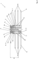
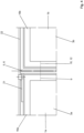
- Figures 1 and 2 show different views of a part of the adjacent swing doors 1a, 1b of a swing door system 2 not according to the present invention.
- Each of the adjacent swing doors 1a, 1b comprising transparent panes 3a, 3b.
- the transparent panes 3a, 3b are spaced apart from each other by spacers 4a, 4b.
- the swing door system 2 further comprises a mullion 5 that has a T-shaped cross-section, wherein a part 6 of the mullion 5 reaches in between the adjacent swing doors 1a, 1b, when the swing doors 1a, 1b are in the closed position. It should be noted that the part 6 can be shorter such that it does not reach in between the adjacent swing doors 1a, 1b.
- FIG. 1 further shows that the mullion 5 comprises two sealing surfaces 7a, 7b each comprising a gasket 8a, 8b.
- Each of the swing doors 1a, 1b comprises a profile 14a, 14b, a layer 15a, 15b and a print 16a, 16b that form a non-transparent area on each swing door 1a, 1b.
- the non-transparent areas of the swing doors 1a, 1b are each proximal to the mullion 5 when the swing doors 1a, 1b are in the closed position.
- the non-transparent areas and the mullion 5 together define a non-transparent region 9 that is marked in figures 1 and 2 with a dashed square. Depending on the horizontal viewing angle, the horizontal diameter 10 of the non-transparent region 9 can be different.
- Figure 2 shows that the depth 11 of the non-transparent region 9 is defined as the horizontal diameter 10 of the non-transparent region 9 being viewed under an horizontal viewing angle of 0° or 180° with respect to the plane in which the swing doors 1a, 1b are arranged when the swing doors 1a, 1b are in a closed position, i.e. the right or left side of the dashed square.
- the width 12 of the non-transparent region 9 is defined as the horizontal diameter 10 of the non-transparent region 9 being viewed under an horizontal viewing angle of 90° with respect to the plane in which the swing doors 1a, 1b being arranged when the swing doors 1a, 1b are in a closed position.
- the width 12 corresponds to the front side of the dashed square.
- the depth 11 and the width 12 of the non-transparent region 9 are extremely short and correspond at least essentially to the depth 30 and width 31 of the mullion 5. Because of the low depth 11 of the non-transparent region 9, the visibility inside of the freezer device is improved when the customer is viewing slantwise into the freezer. The low width 12 of the non-transparent region 9 improves the visibility during the selection phase, i.e. when a person is standing in front of the closed swing doors 1a, 1b.
- each of the gaskets 8a, 8b comprise a magnet 13a, 13b.
- Each magnet 13a, 13b is positioned near the part 6 of the mullion 5.
- a solid L-shaped profile 14a, 14b protects each of the adjacent swing doors 1a, 1b. It should be noted that the L-shaped profile 14a, 14b forms a part of the non-transparent region 9 since it blocks a person's view of the products. In the closed position of the swing doors 1a, 1b the legs of each L-shaped profile 14a, 14b are parallel to the sealing surface 7a, 7b and the part 6 of the mullion 5.
- the L-shaped profile 14a, 14b comprises a layer 15a, 15b of a material, preferably of metal, for example of steel, that interacts with the magnets 13a, 13b when the swing doors 1a, 1b are in the closed position.
- the swing doors 1a, 1b are held securely in the closed position such that the sealing of the inside of the freezer device is improved and the swing doors 1a, 1b can still be opened easily.
- the L-shaped profile 14a, 14b itself can be made of such a material that interacts with the magnets 13a, 13b.
- Each of the adjacent swing doors 1a, 1b may comprise a print 16a, 16b with a non-transparent ink in the non-transparent region 10 as indicated only in figure 2 .
- the rotating axis 17 of the left swing door 1b is positioned in the non-transparent region 9 with a distance 18 of 5 mm away from the external surface of the L-shaped profile 14a, 14b.
- the rotating axis 17 is off-centered, i.e. is positioned in alignment with the external transparent pane 3a.
- the depth 11 of the non-transparent region 9 is here 42 mm, wherein the width 12 of the non-transparent region 9 is 45 mm.
- the thickness 19 of each swing door 1a, 1b without the L-shaped profile 14a, 14b is 26 mm.
- the gap 20 between the swing doors 1a, 1b in the closed position is 5 mm.
- the horizontal diameter 10' of the non-transparent region 9 is 55 mm, i.e. the length defined by the left end of the print 15a and the right end of the sealing surface 7b.
- FIGS 3 and 4 show another embodiment of a swing door system 2 not according to the invention.
- the swing door system 2 comprises two adjacent swing doors 1a, 1b, wherein each swing door 1a, 1b includes transparent panes 3a, 3b being spaced from each other by spacers 4a, 4b.
- a mullion 5 is arranged.
- the mullion 5 is T-shaped and comprises a part 6 that reaches between the adjacent swing doors 1a, 1b, when the swing doors 1a, 1b are in the closed position. It is possible that the part 6 is shorter, such that it does not reach in between the adjacent swing doors 1a, 1b.
- the depth 30 of the mullion 5 is shorter than the depth 11 of the non-transparent region 9.
- the width 31 of the mullion 5 equals the width 12 of the non-transparent region 9.
- the mullion further comprises sealing surfaces 7a, 7b onto which the gaskets 8a, 8b are fixed, for example glued or snapped into.
- the adjacent swing doors include wedges 23a, 23b that are made of a material that interacts with the magnets 13a, 13b of the gaskets.
- the wedges 23a, 23b are made of steel.
- the sealing surfaces 7a, 7b of the mullion 5 are inclined with respect to the transparent panes 3a, 3b when the adjacent swing doors 1a, 1b are in the closed position.
- Figure 4 further shows that the left swing door 1 comprises a hinge element 21, such that the swing door 1a can be rotatable mounted to horizontal profile 22 of an outer frame.
- the right swing door 1b can comprise a hinge on its not shown right side.
- FIGS 5 and 6 show another embodiment of a swing door system 2 not according to the invention.
- the swing door system 2 comprises two adjacent swing doors 1a, 1b, wherein each swing door 1a, 1b includes transparent panes 3a, 3b being spaced from each other by spacers 4a, 4b.
- a mullion 5 is arranged.
- the mullion 5 is T-shaped and comprises a part 6 that reaches between the adjacent swing doors 1a, 1b, when the swing doors 1a, 1b are in the closed position.
- the depth 30 of the mullion 5 is shorter than the depth 11 of the non-transparent region 9.
- the width 31 of the mullion 5 equals the width 12 of the non-transparent region 9.
- the swing door system 2 corresponds to the embodiment shown in figures 1 and 2 .
- the rotating axis of the left door 1a is arranged between the adjacent swing doors 1a, 1b.
- shear forces are minimized that are acting on the gaskets 8a, 8b when the swing doors 1a, 1b are opened and the right door 1b is prevented from blocking the left door 1a, when the left door 1 is opened.
- Figure 6 further shows that the left swing door 1 comprises a hinge 21, such that the swing door 1a can be rotatable mounted to a horizontal profile 22 of an outer frame.
- the right swing door 1b can comprise a hinge on its not shown right side
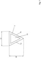
- Figure 7 shows a cross-sectional view parallel to the opening direction of a mullion 5 according to a further embodiment of the present invention.
- the mullion 5 has a triangle shaped cross section. Therefore, the sealing surfaces 7a, 7b of the mullion 5 are inclined with respect to the not shown transparent pane of the adjacent swing doors when the swing doors are in the closed position.
- a triangle shaped mullion 5 has the advantage that the inner part 24 of the mullion 5 can serve as a cable duct, heat pipes, heating elements or other elements.
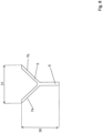
- Figure 8 shows a cross-sectional view parallel to the opening direction of a mullion 5 according to a further embodiment of the present invention.
- the mullion 5 has a Y-shaped cross section. Therefore, the sealing surfaces 7a, 7b of the mullion 5 are inclined with respect to the not shown pane of the adjacent swing doors when the swing doors are in the closed position.
- the part 6 of the Y-shaped mullion 5 can reach in between the not shown adjacent swing doors. Furthermore, part 6 can be realized shorter, such that it does not reach in between the adjacent swing doors.
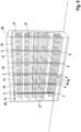
- FIG 9 shows a perspective view of a freezer device 25 according to an embodiment of the present invention.
- the freezer device 25 comprises a cabinet 26 and three swing door systems 2 each including two adjacent swing doors 1a, 1b and a mullion 5.
- the customer can see the products 27 through the transparent panes 3a, 3b of the swing doors 1a, 1b. Due to the low depth 11 and low width 12 of the non-transparent region 9, the person's view of the products 27 is improved when the person is viewing slantwise into the freezer device 2. Furthermore, the low width 12 of the non-transparent region 9 improves the view on the products 27, when the person stands in front of the freezer device 2.
- the freezer device 2 comprises an energy source 28 that is connected with an interface 29, which enables to provide energy to a heating element and/or light elements inside the swing doors 1a, 1b.
- FIG 10 shows an embodiment of a swing door system 2 according to the invention.
- the swing door system 2 comprises two adjacent swing doors 1a, 1b, wherein each swing door 1a, 1b includes transparent panes 3a, 3b being spaced from each other by spacers 4a, 4b.
- a mullion 5 is arranged.
- the mullion 5 is essentially triangle shaped and comprises a part 6 that reaches between the adjacent swing doors 1a, 1b, when the swing doors 1a, 1b are in the closed position. It is possible that the part 6 is shorter, such that it does not reach in between the adjacent swing doors 1a, 1b but at least points in this direction.
- an insulation profile 33 is attached to the mullion 5.
- the insulation profile 33 comprises a space 38 that is filled with a thermally insulating material 34.
- the space 38 is defined by a cavity, such that the insulation profile 33 is a hollow profile.
- the insulation profile 33 is firmly bonded to the mullion 5 with bonding material 39, for example with an adhesive tape.
- the insulation profile 33 can be attached at different fixation points or over its whole length to the mullion 5.
- the insulation profile 33 comprises protuberances 35 that fit into recesses 36 of the mullion 5 for providing a force-fit and/or form-fit connection.
- the mullion 5 further comprises a passage 37 for mounting the mullion 5 to the horizontal profiles, for example with screws.
- Each of the swing doors 1a, 1b comprises an L-shaped profile 14a, 14b.
- gaskets 8a, 8b are attached to the mullion 5 and the insulation profile 33. When the swing doors 1a, 1b are in the closed position the gaskets 8a, 8b form a barrier between the mullion 5 and the interior of the freezer. Additionally, the gaskets 8a, 8b are arranged such as to form a barrier between the L-shaped profiles 14a, 14b and the interior of the freezer when the swing doors 1a, 1b are in the closed position. By providing these two barriers, a very good thermal insulation is achieved such that a heating of the swing doors 1a, 1b is not necessary.
- each of the gaskets 8a, 8b comprises a magnet 13a, 13b.
- the L-shaped profile 14a, 14b comprises a layer 15a, 15b of a material, preferably of metal, for example of steel, that interacts with the magnets 13a, 13b when the swing doors 1a, 1b are in the closed position. Thereby the swing doors 1a, 1b are held securely in the closed position such that the sealing of the inside of the freezer device is improved and the swing doors 1a, 1b can still be opened easily.
- the L-shaped profile 14a, 14b itself can be made of such a material that interacts with the magnets 13a, 13b.
Landscapes
- Engineering & Computer Science (AREA)
- Physics & Mathematics (AREA)
- Thermal Sciences (AREA)
- Mechanical Engineering (AREA)
- Chemical & Material Sciences (AREA)
- Combustion & Propulsion (AREA)
- General Engineering & Computer Science (AREA)
- Refrigerator Housings (AREA)
- Wing Frames And Configurations (AREA)
- Securing Of Glass Panes Or The Like (AREA)
Claims (16)
- Schwingtürsystem (2) zur Verwendung mit einer Tiefkühlvorrichtung (25), mit zwei benachbarten Schwingtüren (1a, 1b) und zumindest einem Mittelprofil (5), das in Kontakt mit den Schwingtüren (1a, 1b) ist, wobeijede Schwingtür (1a, 1b) eine transparente Scheibe (3a, 3b) und einen nicht-transparenten Bereich aufweist, wobei jeder nicht-transparente Bereich nah an dem Mittelprofil (5) angeordnet ist, wenn sich die Schwingtüren (1a, 1b) in der geschlossenen Position befinden, wobeidie nicht-transparenten Bereiche und das Mittelprofil (5) einen nicht-transparenten Abschnitt (9) definieren, und wobei unter einem horizontalen Blickwinkel zwischen 0° und 180° relativ zu der Ebene, in der die Schwingtüren (1a, 1b) angeordnet sind, wenn die Schwingtüren (1a, 1b) sich in der geschlossenen Position befinden, alle horizontalen Durchmesser (10, 10') des nicht-transparenten Abschnitts (9) kleiner sind als 100 mm, vorzugsweise kleiner sind als 80 mm, weiter vorzugsweise kleiner sind als 70 mm, besonders bevorzugter Weise kleiner sind als 60 mm, undwobei der horizontale Blickwinkel der Winkel zwischen der Projektion des Blickwinkels in eine horizontale Ebene hinein und der Ebene, in der die Schwingtüren (1a, 1b) angeordnet sind, wenn sich die Schwingtüren (1a, 1b) in der geschlossenen Position befinden, ist und wobei sich die Ebene, in der die Schwingtüren (1a, 1b) angeordnet sind, wenn sich die Schwingtüren (1a, 1b) in der geschlossenen Position befinden, auf die Oberfläche der transparenten Scheibe (3a, 3b) außerhalb der genutzten Tiefkühlvorrichtung (25) bezieht,dadurch gekennzeichnet, dass ein Isolierprofil (33) an dem Mittelprofil (5) befestigt ist, wobei das Isolierprofil (33) form- und/oder kraftschlüssig am Mittelprofil (5) befestigt ist, oder wobei das Isolierprofil (33) stoffschlüssig mit dem Mittelprofil (5) verbunden ist.
- Schwingtürsystem (2) nach Anspruch 1, wobei unter einem horizontalen Blickwinkel zwischen 0° und 180° relativ zu der Ebene, in der die Schwingtüren (1a, 1b) angeordnet sind, wenn die Schwingtüren (1a, 1b) sich in der geschlossenen Position befinden, zumindest einer der horizontalen Durchmesser (10, 10') des nicht-transparenten Abschnitts (9) kleiner ist als 80 mm, vorzugsweise kleiner als 70 mm, weiter vorzugsweise kleiner als 50 mm, besonders bevorzugter Weise kleiner ist als 45 mm.
- Schwingtürsystem (2) nach Anspruch 1 oder 2, wobei unter einem horizontalen Blickwinkel zwischen 0° und 180° relativ zu der Ebene, in der die Schwingtüren (1a, 1b) angeordnet sind, wenn die Schwingtüren (1a, 1b) sich in der geschlossenen Position befinden, das Verhältnis zwischen dem längsten horizontalen Durchmesser (10, 10') des nicht-transparenten Abschnitts (9) und dem kürzesten horizontalen Durchmesser (10, 10') des nicht-transparenten Abschnitts (9) kleiner ist als 2, vorzugsweise kleiner ist als 1,5, weiter vorzugsweise kleiner ist als 1,2.
- Schwingtürsystem (2) nach einem der Ansprüche 1 bis 3, wobei die Breite (12) des nicht-transparenten Abschnitts (9) kleiner ist als 70 mm, vorzugsweise kleiner ist als 60 mm, weiter vorzugsweise kleiner ist als 50 mm, besonders bevorzugter Weise kleiner ist als 45 mm, und/oder
wobei die Breite (12) des nicht-transparenten Abschnitts (9) in dem Bereich von 25 mm bis 60 mm, vorzugsweise in dem Bereich von 25 mm bis 50 mm, besonders bevorzugter Weise in dem Bereich von 25 mm bis 40 mm, liegt. - Schwingtürsystem (2) nach einem der Ansprüche 1 bis 4, wobei die Tiefe (11) des nicht-transparenten Abschnitts (9) kleiner ist als 70 mm, vorzugsweise kleiner ist als 60 mm, weiter vorzugsweise kleiner ist als 50 mm, besonders bevorzugter Weise kleiner ist als 45 mm, und/oderwobei die Tiefe (11) des nicht-transparenten Abschnitts (9) im Bereich zwischen 25 mm bis 60 mm, vorzugsweise im Bereich von 25 mm bis 50 mm, besonders bevorzugter Weise im Bereich von 25 mm bis 40 mm, liegt, und/oderwobei ein Querschnitt des Mittelprofils (5) T-förmig, Y-förmig oder dreieckig ausgebildet ist, und/oderwobei das Mittelprofil (5) einteilig ausgebildet ist, zumindest in dem Bereich, der sich von dem unteren Ende bis zu dem oberen Ende der benachbarten Schwingtüren (1a, 1b) erstreckt, oderwobei das Mittelprofil (5) zwei Elemente aufweist, die miteinander form- und/oder kraft- und/oder stoffschlüssig verbunden sind, zumindest in dem Bereich, der sich von dem unteren Ende bis zu dem oberen Ende der benachbarten Schwingtüren (1a, 1b) erstreckt, und/oderwobei das Mittelprofil (5) einen Hohlraum aufweist, oderwobei das Mittelprofil (5) massiv ausgebildet ist.
- Schwingtürsystem (2) nach einem der Ansprüche 1 bis 5, wobei ein Teil (6) des Mittelprofils (5) zwischen die beiden benachbarten Schwingtüren (1a, 1b) reicht, wenn sich die Schwingtüren (1a, 1b) in der geschlossenen Position befinden, und
wobei optional: das Isolierprofil (33) mit einem Verbundmaterial (39) stoffschlüssig mit dem Mittelprofil (5) verbunden ist. - Schwingtürsystem (2) nach Anspruch 6, wobei das Isolierprofil (33) aus Kunststoff, vorzugsweise aus einem Polymer, weiter vorzugsweise aus Polyvinylchlorid, oder aus Metall hergestellt ist.
- Schwingtürsystem (2) nach Anspruch 6 oder 7, wobei das Isolierprofil (33) einen Raum (38) aufweist, vorzugsweise wobei das Isolierprofil (33) zumindest teilweise einen C-förmigen Querschnitt aufweist, und wobei der Raum (38) des Isolierprofils (33) mit einem wärmeisolierenden Material (34) gefüllt ist, vorzugsweise mit einem Schaum, weiter vorzugsweise mit einem Polyurethanschaum, und/oder
wobei das Mittelprofil (5) mindestens eine, vorzugsweise mindestens zwei Dichtungsflächen (7a, 7b) aufweist und wobei vorzugsweise jede der beiden Dichtungsflächen (7a, 7b) in Bezug auf die Ebene, in der die Schwenktüren (1a, 1b) angeordnet sind, wenn sich die Schwenktüren (1a, 1b) in der geschlossenen Position befinden, geneigt ist. - Schwingtürsystem (2) nach einem der Ansprüche 1 bis 8, wobei eine Dichtung (8a, 8b) an dem Mittelprofil (5) befestigt ist, und/oderwobei eine Dichtung (8a, 8b) an dem Isolierprofil (33) befestigt ist, undwobei optional die Dichtung (8a, 8b) und das Isolierprofil (33) so angeordnet sind, dass sie eine Barriere zwischen dem Mittelprofil (5) und dem Innenraum der Tiefkühlvorrichtung (25) bilden, wenn sich die benachbarten Schwingtüren (1a, 1b) in der geschlossenen Position befinden.
- Schwingtürsystem (2) nach einem der Ansprüche 1 bis 9, wobei eine Dichtung (8a, 8b) an mindestens einer der Schwingtüren (1a, 1b) befestigt ist, und/oderwobei Magnetmittel (13a, 13b) angeordnet sind, um die Schwingtüren (1a, 1b) magnetisch mit dem Mittelprofil (5) zu verbinden, wenn sich die Schwingtüren (1a, 1b) in der geschlossenen Position befinden, und/oderwobei die transparente Scheibe (3a, 3b) der Schwingtür (1a, 1b) eine gasgefüllte Isolations-Glaseinheit oder eine Vakuum-Isolations-Glaseinheit aufweist, und/oderwobei zumindest eine der Schwingtüren (1a, 1b) zumindest teilweise in dem nicht-transparenten Abschnitt (9) bedruckt (16a, 16b) ist, vorzugsweise mit einer nicht-transparenten Tinte.
- Schwingtürsystem (2) nach einem der Ansprüche 1 bis 10, wobei das Mittelprofil (5) aus Metall, vorzugsweise aus Aluminium oder aus Stahl, oder aus Kunststoff, vorzugsweise aus faserverstärktem Kunststoff, oder aus mit einem Kunststoff beschichteten Metall, vorzugsweise aus mit Kunststoff beschichtetem Aluminium oder aus mit Kunststoff beschichtetem Stahl, hergestellt ist, und/oderwobei keine Heizmittel angeordnet sind, um zumindest einen Teil der Schwingtüren (1a, 1b) zu heizen und/oderwobei Heizmittel angeordnet sind, um zumindest einen Teil des Mittelprofils (5) und/oder zumindest einen Teil eines horizontalen Profils (22) zu heizen und/oderwobei Leuchtmittel angeordnet sind, um zumindest einen Teil des Gehäuses (26) zu beleuchten.
- Schwingtürsystem (2) nach einem der Ansprüche 1 bis 11, wobei jede Schwingtür (1a, 1b) zumindest teilweise von einem Profil (14a, 14b) umgeben ist, vorzugsweise von einem massiven Profil (14a, 14b), weiter vorzugsweise von einem massiven Profil (14a, 14b) mit einem L-förmigen Querschnitt, und
wobei, optional, die Dichtung (8a, 8b) so angeordnet ist, dass sie eine Barriere zwischen dem Profil (14a, 14b) und dem Innenraum der Tiefkühlvorrichtung (25) bildet, wenn sich die benachbarten Schwingtüren (1a, 1b) in der geschlossenen Position befinden. - Schwingtürsystem (2) nach einem der Ansprüche 1 bis 12, wobei die Drehachse (17) zumindest einer der Schwingtüren (1a, 1b) in dem nicht-transparenten Abschnitt (9) angeordnet ist, und/oderwobei die Drehachse (17) zumindest einer der Schwingtüren (1a, 1b) außermittig in Bezug auf die Tiefe des nicht-transparenten Abschnitts (9) angeordnet ist, und/oderwobei die Drehachse (17) in dem Bereich zwischen den benachbarten Schwingtüren (1a, 1b) angeordnet ist.
- Schwingtürsystem (2) nach einem der Ansprüche 1 bis 13, wobei zumindest eine der Schwingtüren (1a, 1b) ein Gelenk (21) an gegenüberliegenden Enden dieser zumindest einen Schwingtür (1a, 1b) aufweist.
- Schwingtürsystem (2) nach einem der Ansprüche 1 bis 14, wobei das Isolierprofil zumindest an verschiedenen Befestigungspunkten form- und/oder kraftschlüssig an dem Mittelprofil befestigt ist.
- Tiefkühlvorrichtung (25) mit zumindest einem Schwingtürsystem (2) nach einem der Ansprüche 1 bis 15, dass an einem Gehäuse (26) angeordnet ist, so dass die Öffnungsrichtung des Schwingtürsystems horizontal verläuft.
Applications Claiming Priority (2)
| Application Number | Priority Date | Filing Date | Title |
|---|---|---|---|
| EP19172797.3A EP3735867B1 (de) | 2019-05-06 | 2019-05-06 | Schwenktürsystem und gefriervorrichtung |
| DE202019105967.2U DE202019105967U1 (de) | 2019-05-06 | 2019-10-28 | Schwingtürsystem und eine Tiefkühlvorrichtung |
Publications (3)
| Publication Number | Publication Date |
|---|---|
| EP3735869A1 EP3735869A1 (de) | 2020-11-11 |
| EP3735869B1 true EP3735869B1 (de) | 2024-08-14 |
| EP3735869B8 EP3735869B8 (de) | 2024-09-25 |
Family
ID=66429283
Family Applications (2)
| Application Number | Title | Priority Date | Filing Date |
|---|---|---|---|
| EP19172797.3A Active EP3735867B1 (de) | 2019-05-06 | 2019-05-06 | Schwenktürsystem und gefriervorrichtung |
| EP20174914.0A Active EP3735869B8 (de) | 2019-05-06 | 2020-05-15 | Schwenktürsystem und gefriervorrichtung |
Family Applications Before (1)
| Application Number | Title | Priority Date | Filing Date |
|---|---|---|---|
| EP19172797.3A Active EP3735867B1 (de) | 2019-05-06 | 2019-05-06 | Schwenktürsystem und gefriervorrichtung |
Country Status (10)
| Country | Link |
|---|---|
| US (1) | US12185848B2 (de) |
| EP (2) | EP3735867B1 (de) |
| JP (2) | JP2020183864A (de) |
| KR (1) | KR102769500B1 (de) |
| CN (1) | CN111895714A (de) |
| AU (1) | AU2020202636B2 (de) |
| DE (2) | DE202019105363U1 (de) |
| ES (2) | ES2870675T3 (de) |
| MX (1) | MX2020004658A (de) |
| ZA (1) | ZA202002440B (de) |
Families Citing this family (5)
| Publication number | Priority date | Publication date | Assignee | Title |
|---|---|---|---|---|
| EP3735866B1 (de) * | 2019-05-06 | 2021-06-30 | Schott Ag | Schwenktürsystem und gefriervorrichtung |
| USD947663S1 (en) * | 2019-07-01 | 2022-04-05 | Endura Products, Llc | Door mullion |
| USD934671S1 (en) * | 2019-07-01 | 2021-11-02 | Endura Products, Llc | Door jamb |
| US12480357B2 (en) | 2021-05-04 | 2025-11-25 | Endura Products, Llc | Door stile with composite edge banding and method of manufacturing the same |
| CN121185028B (zh) * | 2025-11-26 | 2026-02-03 | 云峰机械(福建)有限公司 | 一种连续式真空冷却机 |
Family Cites Families (28)
| Publication number | Priority date | Publication date | Assignee | Title |
|---|---|---|---|---|
| US2137165A (en) * | 1938-04-09 | 1938-11-15 | Gen Electric | Refrigerator cabinet |
| US2449384A (en) * | 1946-01-09 | 1948-09-14 | Seeger Sunbeam Corp | Refrigerator mullion construction for preventing condensation |
| US4004370A (en) * | 1975-03-03 | 1977-01-25 | Anthony's Manufacturing Company, Inc. | Insulated door mounting frame structure |
| JPS57130190A (en) | 1981-02-06 | 1982-08-12 | Shinko Electric Co Ltd | Coin processor |
| JPS60155881A (ja) | 1984-01-25 | 1985-08-15 | 株式会社日立製作所 | シリコン炉からのアルゴン回収装置 |
| US4588235A (en) * | 1984-09-07 | 1986-05-13 | Barroero Louis F | Refrigerator door structure |
| US4831780A (en) * | 1987-07-07 | 1989-05-23 | Ardco Inc. | Refrigerator door assembly with thermal break frame |
| US6029411A (en) * | 1992-03-12 | 2000-02-29 | Anthony, Inc. | Composite door and frame |
| WO2000075561A1 (en) * | 1999-06-07 | 2000-12-14 | Specialty Equipment Companies, Inc. | Display case having a mullion with recessed light fixtures |
| US6406108B1 (en) * | 1999-11-05 | 2002-06-18 | Specialty Equipment Companies, Inc. | Display case with door-mounted internal lighting |
| AUPQ459599A0 (en) * | 1999-12-09 | 2000-01-13 | Orford Pty Ltd | Improved mullion assembly |
| JP2002364978A (ja) * | 2001-06-08 | 2002-12-18 | Matsushita Refrig Co Ltd | 冷蔵庫 |
| US20060245205A1 (en) * | 2005-04-29 | 2006-11-02 | Hughes Robert M | Fiber optically illuminated display cabinet and a fiber optic cable light distribution assembly therefor |
| US20070022667A1 (en) * | 2005-07-28 | 2007-02-01 | Gemtron Corporation | Product display case door frame having an integrated raceway |
| WO2008029801A1 (fr) | 2006-09-04 | 2008-03-13 | Nippon Sheet Glass Company, Limited | Porte en verre transparente pour une chambre de refroidissement |
| US8070305B2 (en) * | 2008-07-25 | 2011-12-06 | Hussmann Corporation | Mullion assembly for a refrigerated merchandiser |
| US20120062080A1 (en) * | 2009-04-30 | 2012-03-15 | John Maslen | Door system for refrigerated display cabinets |
| US9554660B2 (en) * | 2009-08-19 | 2017-01-31 | Thermoseal Industries, Llc | Reach-in door for refrigerated cabinets |
| AU2010100496B4 (en) | 2010-05-21 | 2013-08-22 | Maslen Technology Australia Pty Ltd | Internal lighting for refrigerated display cabinets |
| US9157675B2 (en) * | 2010-06-09 | 2015-10-13 | Hill Phoenix, Inc. | Insulated case construction |
| JP5640501B2 (ja) * | 2010-06-30 | 2014-12-17 | 富士電機株式会社 | ショーケース用扉体 |
| WO2013163533A2 (en) * | 2012-04-26 | 2013-10-31 | Anthony, Inc. | Thermally efficient refrigerator door and frame |
| EP2879553B1 (de) * | 2012-08-02 | 2017-10-04 | Carrier Corporation | Verkaufskühlvitrine |
| EP3110294B1 (de) * | 2014-02-28 | 2021-09-01 | Carrier Corporation | Verkaufskühlvitrine |
| US9389013B2 (en) * | 2014-08-15 | 2016-07-12 | Anthony International | Thermal frame for a refrigerated enclosure |
| JP6722884B2 (ja) | 2016-04-15 | 2020-07-15 | パナソニックIpマネジメント株式会社 | 照明装置及びリーチインショーケース |
| WO2018080482A1 (en) * | 2016-10-26 | 2018-05-03 | Hussmann Corporation | Case frame and door assembly for a merchandiser |
| US10575660B2 (en) * | 2017-08-29 | 2020-03-03 | Anthony, Inc. | Glass assembly with clear edging |
-
2019
- 2019-05-06 ES ES19172797T patent/ES2870675T3/es active Active
- 2019-05-06 EP EP19172797.3A patent/EP3735867B1/de active Active
- 2019-09-27 DE DE202019105363.1U patent/DE202019105363U1/de active Active
- 2019-10-28 DE DE202019105967.2U patent/DE202019105967U1/de active Active
-
2020
- 2020-04-20 AU AU2020202636A patent/AU2020202636B2/en active Active
- 2020-05-01 JP JP2020080955A patent/JP2020183864A/ja active Pending
- 2020-05-04 KR KR1020200053368A patent/KR102769500B1/ko active Active
- 2020-05-05 ZA ZA2020/02440A patent/ZA202002440B/en unknown
- 2020-05-06 US US16/868,108 patent/US12185848B2/en active Active
- 2020-05-06 CN CN202010371721.9A patent/CN111895714A/zh active Pending
- 2020-05-15 ES ES20174914T patent/ES2994498T3/es active Active
- 2020-05-15 EP EP20174914.0A patent/EP3735869B8/de active Active
- 2020-07-13 MX MX2020004658A patent/MX2020004658A/es unknown
-
2024
- 2024-12-06 JP JP2024214033A patent/JP2025027144A/ja active Pending
Also Published As
| Publication number | Publication date |
|---|---|
| US20200352355A1 (en) | 2020-11-12 |
| CN111895714A (zh) | 2020-11-06 |
| KR20200130149A (ko) | 2020-11-18 |
| EP3735867A1 (de) | 2020-11-11 |
| AU2020202636B2 (en) | 2025-10-16 |
| DE202019105363U1 (de) | 2019-10-23 |
| BR102020009797A8 (pt) | 2023-10-03 |
| EP3735867B1 (de) | 2021-04-07 |
| ZA202002440B (en) | 2021-05-26 |
| US12185848B2 (en) | 2025-01-07 |
| ES2994498T3 (en) | 2025-01-24 |
| JP2025027144A (ja) | 2025-02-26 |
| EP3735869B8 (de) | 2024-09-25 |
| AU2020202636A1 (en) | 2020-11-26 |
| BR102020009797A2 (pt) | 2020-12-01 |
| ES2870675T3 (es) | 2021-10-27 |
| EP3735869A1 (de) | 2020-11-11 |
| JP2020183864A (ja) | 2020-11-12 |
| KR102769500B1 (ko) | 2025-02-17 |
| MX2020004658A (es) | 2020-11-09 |
| DE202019105967U1 (de) | 2019-11-07 |
Similar Documents
| Publication | Publication Date | Title |
|---|---|---|
| US12185848B2 (en) | Swing door system and a freezer device | |
| EP3450892B1 (de) | Kühlthekentür und kühltheke | |
| EP3911811B1 (de) | Rahmeneinheit mit vakuumisoliertem glaselement | |
| CN100487347C (zh) | 致冷器具 | |
| EP3748263B1 (de) | Gefrier- oder kühlvorrichtung | |
| US9554660B2 (en) | Reach-in door for refrigerated cabinets | |
| US12082716B2 (en) | Swing door system and a freezer device | |
| AU2020202228B2 (en) | Swing door system and freezer device with a swing door system | |
| BR102020009797B1 (pt) | Sistema de portas giratórias e um dispositivo congelador | |
| BR112021022155B1 (pt) | Sistema de porta oscilante e um dispositivo congelador | |
| US20250160541A1 (en) | Display door for temperature-controlled enclosure | |
| US20260053280A1 (en) | Temperature-controlled enclosure with clear mullion | |
| HK40005707B (en) | Refrigerated display case door and refrigerated display case | |
| HK40005707A (en) | Refrigerated display case door and refrigerated display case | |
| JP2000002051A (ja) | 窓 | |
| CA3252740A1 (en) | Display door for temperature-controlled enclosure | |
| EP2674561B1 (de) | Wärmebeständiges Fensterrahmenglied und Fensteranordnung |
Legal Events
| Date | Code | Title | Description |
|---|---|---|---|
| PUAI | Public reference made under article 153(3) epc to a published international application that has entered the european phase |
Free format text: ORIGINAL CODE: 0009012 |
|
| STAA | Information on the status of an ep patent application or granted ep patent |
Free format text: STATUS: REQUEST FOR EXAMINATION WAS MADE |
|
| 17P | Request for examination filed |
Effective date: 20200717 |
|
| AK | Designated contracting states |
Kind code of ref document: A1 Designated state(s): AL AT BE BG CH CY CZ DE DK EE ES FI FR GB GR HR HU IE IS IT LI LT LU LV MC MK MT NL NO PL PT RO RS SE SI SK SM TR |
|
| AX | Request for extension of the european patent |
Extension state: BA ME |
|
| RIN1 | Information on inventor provided before grant (corrected) |
Inventor name: DIEDERICHS, JOCHEN Inventor name: SMAJSER, PETR Inventor name: RAFAJ, MARTIN Inventor name: LAMMEL, MICHAEL Inventor name: LEDERHOFER, BENJAMIN Inventor name: HELLER, MARKUS Inventor name: KUKULIS, JAROSLAV Inventor name: PLACEK, JAROSLAV |
|
| RAP3 | Party data changed (applicant data changed or rights of an application transferred) |
Owner name: SCHOTT FLAT GLASS CR, S.R.O. Owner name: SCHOTT AG |
|
| STAA | Information on the status of an ep patent application or granted ep patent |
Free format text: STATUS: EXAMINATION IS IN PROGRESS |
|
| 17Q | First examination report despatched |
Effective date: 20221117 |
|
| P01 | Opt-out of the competence of the unified patent court (upc) registered |
Effective date: 20230516 |
|
| GRAP | Despatch of communication of intention to grant a patent |
Free format text: ORIGINAL CODE: EPIDOSNIGR1 |
|
| STAA | Information on the status of an ep patent application or granted ep patent |
Free format text: STATUS: GRANT OF PATENT IS INTENDED |
|
| INTG | Intention to grant announced |
Effective date: 20240215 |
|
| GRAS | Grant fee paid |
Free format text: ORIGINAL CODE: EPIDOSNIGR3 |
|
| GRAA | (expected) grant |
Free format text: ORIGINAL CODE: 0009210 |
|
| STAA | Information on the status of an ep patent application or granted ep patent |
Free format text: STATUS: THE PATENT HAS BEEN GRANTED |
|
| AK | Designated contracting states |
Kind code of ref document: B1 Designated state(s): AL AT BE BG CH CY CZ DE DK EE ES FI FR GB GR HR HU IE IS IT LI LT LU LV MC MK MT NL NO PL PT RO RS SE SI SK SM TR |
|
| REG | Reference to a national code |
Ref country code: GB Ref legal event code: FG4D |
|
| REG | Reference to a national code |
Ref country code: CH Ref legal event code: EP |
|
| REG | Reference to a national code |
Ref country code: CH Ref legal event code: PK Free format text: BERICHTIGUNG B8 |
|
| RAP4 | Party data changed (patent owner data changed or rights of a patent transferred) |
Owner name: SCHOTT TERMOFROST S.R.O. Owner name: SCHOTT AG |
|
| REG | Reference to a national code |
Ref country code: DE Ref legal event code: R096 Ref document number: 602020035620 Country of ref document: DE |
|
| REG | Reference to a national code |
Ref country code: IE Ref legal event code: FG4D |
|
| REG | Reference to a national code |
Ref country code: LT Ref legal event code: MG9D |
|
| REG | Reference to a national code |
Ref country code: NL Ref legal event code: MP Effective date: 20240814 |
|
| PG25 | Lapsed in a contracting state [announced via postgrant information from national office to epo] |
Ref country code: NO Free format text: LAPSE BECAUSE OF FAILURE TO SUBMIT A TRANSLATION OF THE DESCRIPTION OR TO PAY THE FEE WITHIN THE PRESCRIBED TIME-LIMIT Effective date: 20241114 |
|
| REG | Reference to a national code |
Ref country code: AT Ref legal event code: MK05 Ref document number: 1712442 Country of ref document: AT Kind code of ref document: T Effective date: 20240814 |
|
| PG25 | Lapsed in a contracting state [announced via postgrant information from national office to epo] |
Ref country code: FI Free format text: LAPSE BECAUSE OF FAILURE TO SUBMIT A TRANSLATION OF THE DESCRIPTION OR TO PAY THE FEE WITHIN THE PRESCRIBED TIME-LIMIT Effective date: 20240814 Ref country code: NL Free format text: LAPSE BECAUSE OF FAILURE TO SUBMIT A TRANSLATION OF THE DESCRIPTION OR TO PAY THE FEE WITHIN THE PRESCRIBED TIME-LIMIT Effective date: 20240814 Ref country code: PL Free format text: LAPSE BECAUSE OF FAILURE TO SUBMIT A TRANSLATION OF THE DESCRIPTION OR TO PAY THE FEE WITHIN THE PRESCRIBED TIME-LIMIT Effective date: 20240814 Ref country code: PT Free format text: LAPSE BECAUSE OF FAILURE TO SUBMIT A TRANSLATION OF THE DESCRIPTION OR TO PAY THE FEE WITHIN THE PRESCRIBED TIME-LIMIT Effective date: 20241216 Ref country code: GR Free format text: LAPSE BECAUSE OF FAILURE TO SUBMIT A TRANSLATION OF THE DESCRIPTION OR TO PAY THE FEE WITHIN THE PRESCRIBED TIME-LIMIT Effective date: 20241115 |
|
| PG25 | Lapsed in a contracting state [announced via postgrant information from national office to epo] |
Ref country code: BG Free format text: LAPSE BECAUSE OF FAILURE TO SUBMIT A TRANSLATION OF THE DESCRIPTION OR TO PAY THE FEE WITHIN THE PRESCRIBED TIME-LIMIT Effective date: 20240814 |
|
| PG25 | Lapsed in a contracting state [announced via postgrant information from national office to epo] |
Ref country code: LV Free format text: LAPSE BECAUSE OF FAILURE TO SUBMIT A TRANSLATION OF THE DESCRIPTION OR TO PAY THE FEE WITHIN THE PRESCRIBED TIME-LIMIT Effective date: 20240814 |
|
| PG25 | Lapsed in a contracting state [announced via postgrant information from national office to epo] |
Ref country code: AT Free format text: LAPSE BECAUSE OF FAILURE TO SUBMIT A TRANSLATION OF THE DESCRIPTION OR TO PAY THE FEE WITHIN THE PRESCRIBED TIME-LIMIT Effective date: 20240814 Ref country code: IS Free format text: LAPSE BECAUSE OF FAILURE TO SUBMIT A TRANSLATION OF THE DESCRIPTION OR TO PAY THE FEE WITHIN THE PRESCRIBED TIME-LIMIT Effective date: 20241214 |
|
| PG25 | Lapsed in a contracting state [announced via postgrant information from national office to epo] |
Ref country code: HR Free format text: LAPSE BECAUSE OF FAILURE TO SUBMIT A TRANSLATION OF THE DESCRIPTION OR TO PAY THE FEE WITHIN THE PRESCRIBED TIME-LIMIT Effective date: 20240814 |
|
| REG | Reference to a national code |
Ref country code: ES Ref legal event code: FG2A Ref document number: 2994498 Country of ref document: ES Kind code of ref document: T3 Effective date: 20250124 |
|
| PG25 | Lapsed in a contracting state [announced via postgrant information from national office to epo] |
Ref country code: RS Free format text: LAPSE BECAUSE OF FAILURE TO SUBMIT A TRANSLATION OF THE DESCRIPTION OR TO PAY THE FEE WITHIN THE PRESCRIBED TIME-LIMIT Effective date: 20241114 |
|
| PG25 | Lapsed in a contracting state [announced via postgrant information from national office to epo] |
Ref country code: RS Free format text: LAPSE BECAUSE OF FAILURE TO SUBMIT A TRANSLATION OF THE DESCRIPTION OR TO PAY THE FEE WITHIN THE PRESCRIBED TIME-LIMIT Effective date: 20241114 Ref country code: PT Free format text: LAPSE BECAUSE OF FAILURE TO SUBMIT A TRANSLATION OF THE DESCRIPTION OR TO PAY THE FEE WITHIN THE PRESCRIBED TIME-LIMIT Effective date: 20241216 Ref country code: PL Free format text: LAPSE BECAUSE OF FAILURE TO SUBMIT A TRANSLATION OF THE DESCRIPTION OR TO PAY THE FEE WITHIN THE PRESCRIBED TIME-LIMIT Effective date: 20240814 Ref country code: NO Free format text: LAPSE BECAUSE OF FAILURE TO SUBMIT A TRANSLATION OF THE DESCRIPTION OR TO PAY THE FEE WITHIN THE PRESCRIBED TIME-LIMIT Effective date: 20241114 Ref country code: NL Free format text: LAPSE BECAUSE OF FAILURE TO SUBMIT A TRANSLATION OF THE DESCRIPTION OR TO PAY THE FEE WITHIN THE PRESCRIBED TIME-LIMIT Effective date: 20240814 Ref country code: LV Free format text: LAPSE BECAUSE OF FAILURE TO SUBMIT A TRANSLATION OF THE DESCRIPTION OR TO PAY THE FEE WITHIN THE PRESCRIBED TIME-LIMIT Effective date: 20240814 Ref country code: IS Free format text: LAPSE BECAUSE OF FAILURE TO SUBMIT A TRANSLATION OF THE DESCRIPTION OR TO PAY THE FEE WITHIN THE PRESCRIBED TIME-LIMIT Effective date: 20241214 Ref country code: HR Free format text: LAPSE BECAUSE OF FAILURE TO SUBMIT A TRANSLATION OF THE DESCRIPTION OR TO PAY THE FEE WITHIN THE PRESCRIBED TIME-LIMIT Effective date: 20240814 Ref country code: GR Free format text: LAPSE BECAUSE OF FAILURE TO SUBMIT A TRANSLATION OF THE DESCRIPTION OR TO PAY THE FEE WITHIN THE PRESCRIBED TIME-LIMIT Effective date: 20241115 Ref country code: FI Free format text: LAPSE BECAUSE OF FAILURE TO SUBMIT A TRANSLATION OF THE DESCRIPTION OR TO PAY THE FEE WITHIN THE PRESCRIBED TIME-LIMIT Effective date: 20240814 Ref country code: BG Free format text: LAPSE BECAUSE OF FAILURE TO SUBMIT A TRANSLATION OF THE DESCRIPTION OR TO PAY THE FEE WITHIN THE PRESCRIBED TIME-LIMIT Effective date: 20240814 Ref country code: AT Free format text: LAPSE BECAUSE OF FAILURE TO SUBMIT A TRANSLATION OF THE DESCRIPTION OR TO PAY THE FEE WITHIN THE PRESCRIBED TIME-LIMIT Effective date: 20240814 |
|
| PG25 | Lapsed in a contracting state [announced via postgrant information from national office to epo] |
Ref country code: RO Free format text: LAPSE BECAUSE OF FAILURE TO SUBMIT A TRANSLATION OF THE DESCRIPTION OR TO PAY THE FEE WITHIN THE PRESCRIBED TIME-LIMIT Effective date: 20240814 Ref country code: SM Free format text: LAPSE BECAUSE OF FAILURE TO SUBMIT A TRANSLATION OF THE DESCRIPTION OR TO PAY THE FEE WITHIN THE PRESCRIBED TIME-LIMIT Effective date: 20240814 Ref country code: DK Free format text: LAPSE BECAUSE OF FAILURE TO SUBMIT A TRANSLATION OF THE DESCRIPTION OR TO PAY THE FEE WITHIN THE PRESCRIBED TIME-LIMIT Effective date: 20240814 |
|
| PG25 | Lapsed in a contracting state [announced via postgrant information from national office to epo] |
Ref country code: SK Free format text: LAPSE BECAUSE OF FAILURE TO SUBMIT A TRANSLATION OF THE DESCRIPTION OR TO PAY THE FEE WITHIN THE PRESCRIBED TIME-LIMIT Effective date: 20240814 |
|
| REG | Reference to a national code |
Ref country code: DE Ref legal event code: R097 Ref document number: 602020035620 Country of ref document: DE |
|
| PLBE | No opposition filed within time limit |
Free format text: ORIGINAL CODE: 0009261 |
|
| STAA | Information on the status of an ep patent application or granted ep patent |
Free format text: STATUS: NO OPPOSITION FILED WITHIN TIME LIMIT |
|
| 26N | No opposition filed |
Effective date: 20250515 |
|
| PG25 | Lapsed in a contracting state [announced via postgrant information from national office to epo] |
Ref country code: SE Free format text: LAPSE BECAUSE OF FAILURE TO SUBMIT A TRANSLATION OF THE DESCRIPTION OR TO PAY THE FEE WITHIN THE PRESCRIBED TIME-LIMIT Effective date: 20240814 |
|
| PGFP | Annual fee paid to national office [announced via postgrant information from national office to epo] |
Ref country code: ES Payment date: 20250630 Year of fee payment: 6 |
|
| REG | Reference to a national code |
Ref country code: CH Ref legal event code: H13 Free format text: ST27 STATUS EVENT CODE: U-0-0-H10-H13 (AS PROVIDED BY THE NATIONAL OFFICE) Effective date: 20251223 |
|
| PG25 | Lapsed in a contracting state [announced via postgrant information from national office to epo] |
Ref country code: LU Free format text: LAPSE BECAUSE OF NON-PAYMENT OF DUE FEES Effective date: 20250515 |
|
| PG25 | Lapsed in a contracting state [announced via postgrant information from national office to epo] |
Ref country code: CH Free format text: LAPSE BECAUSE OF NON-PAYMENT OF DUE FEES Effective date: 20250531 |
|
| REG | Reference to a national code |
Ref country code: BE Ref legal event code: MM Effective date: 20250531 |
|
| PG25 | Lapsed in a contracting state [announced via postgrant information from national office to epo] |
Ref country code: MC Free format text: LAPSE BECAUSE OF FAILURE TO SUBMIT A TRANSLATION OF THE DESCRIPTION OR TO PAY THE FEE WITHIN THE PRESCRIBED TIME-LIMIT Effective date: 20240814 |
|
| PG25 | Lapsed in a contracting state [announced via postgrant information from national office to epo] |
Ref country code: IE Free format text: LAPSE BECAUSE OF NON-PAYMENT OF DUE FEES Effective date: 20250515 |
|
| PG25 | Lapsed in a contracting state [announced via postgrant information from national office to epo] |
Ref country code: BE Free format text: LAPSE BECAUSE OF NON-PAYMENT OF DUE FEES Effective date: 20250531 |
|
| PG25 | Lapsed in a contracting state [announced via postgrant information from national office to epo] |
Ref country code: LT Free format text: LAPSE BECAUSE OF FAILURE TO SUBMIT A TRANSLATION OF THE DESCRIPTION OR TO PAY THE FEE WITHIN THE PRESCRIBED TIME-LIMIT Effective date: 20240814 |
|
| PGFP | Annual fee paid to national office [announced via postgrant information from national office to epo] |
Ref country code: GB Payment date: 20260522 Year of fee payment: 7 |
|
| PGFP | Annual fee paid to national office [announced via postgrant information from national office to epo] |
Ref country code: IT Payment date: 20260525 Year of fee payment: 7 |
|
| PGFP | Annual fee paid to national office [announced via postgrant information from national office to epo] |
Ref country code: DE Payment date: 20260522 Year of fee payment: 7 |
|
| PGFP | Annual fee paid to national office [announced via postgrant information from national office to epo] |
Ref country code: CZ Payment date: 20260507 Year of fee payment: 7 Ref country code: TR Payment date: 20260511 Year of fee payment: 7 |
|
| PGFP | Annual fee paid to national office [announced via postgrant information from national office to epo] |
Ref country code: FR Payment date: 20260526 Year of fee payment: 7 |
|
| PG25 | Lapsed in a contracting state [announced via postgrant information from national office to epo] |
Ref country code: CY Free format text: LAPSE BECAUSE OF FAILURE TO SUBMIT A TRANSLATION OF THE DESCRIPTION OR TO PAY THE FEE WITHIN THE PRESCRIBED TIME-LIMIT Effective date: 20240814 |