EP3735675B1 - Bildannotation - Google Patents
Bildannotation Download PDFInfo
- Publication number
- EP3735675B1 EP3735675B1 EP19711082.8A EP19711082A EP3735675B1 EP 3735675 B1 EP3735675 B1 EP 3735675B1 EP 19711082 A EP19711082 A EP 19711082A EP 3735675 B1 EP3735675 B1 EP 3735675B1
- Authority
- EP
- European Patent Office
- Prior art keywords
- road
- image
- vehicle
- images
- camera
- Prior art date
- Legal status (The legal status is an assumption and is not a legal conclusion. Google has not performed a legal analysis and makes no representation as to the accuracy of the status listed.)
- Active
Links
Images














Classifications
-
- G—PHYSICS
- G06—COMPUTING OR CALCULATING; COUNTING
- G06T—IMAGE DATA PROCESSING OR GENERATION, IN GENERAL
- G06T7/00—Image analysis
- G06T7/70—Determining position or orientation of objects or cameras
- G06T7/73—Determining position or orientation of objects or cameras using feature-based methods
- G06T7/75—Determining position or orientation of objects or cameras using feature-based methods involving models
-
- B—PERFORMING OPERATIONS; TRANSPORTING
- B60—VEHICLES IN GENERAL
- B60W—CONJOINT CONTROL OF VEHICLE SUB-UNITS OF DIFFERENT TYPE OR DIFFERENT FUNCTION; CONTROL SYSTEMS SPECIALLY ADAPTED FOR HYBRID VEHICLES; ROAD VEHICLE DRIVE CONTROL SYSTEMS FOR PURPOSES NOT RELATED TO THE CONTROL OF A PARTICULAR SUB-UNIT
- B60W60/00—Drive control systems specially adapted for autonomous road vehicles
- B60W60/001—Planning or execution of driving tasks
-
- G—PHYSICS
- G01—MEASURING; TESTING
- G01C—MEASURING DISTANCES, LEVELS OR BEARINGS; SURVEYING; NAVIGATION; GYROSCOPIC INSTRUMENTS; PHOTOGRAMMETRY OR VIDEOGRAMMETRY
- G01C21/00—Navigation; Navigational instruments not provided for in groups G01C1/00 - G01C19/00
- G01C21/26—Navigation; Navigational instruments not provided for in groups G01C1/00 - G01C19/00 specially adapted for navigation in a road network
- G01C21/28—Navigation; Navigational instruments not provided for in groups G01C1/00 - G01C19/00 specially adapted for navigation in a road network with correlation of data from several navigational instruments
- G01C21/30—Map- or contour-matching
-
- G—PHYSICS
- G01—MEASURING; TESTING
- G01C—MEASURING DISTANCES, LEVELS OR BEARINGS; SURVEYING; NAVIGATION; GYROSCOPIC INSTRUMENTS; PHOTOGRAMMETRY OR VIDEOGRAMMETRY
- G01C21/00—Navigation; Navigational instruments not provided for in groups G01C1/00 - G01C19/00
- G01C21/26—Navigation; Navigational instruments not provided for in groups G01C1/00 - G01C19/00 specially adapted for navigation in a road network
- G01C21/34—Route searching; Route guidance
- G01C21/36—Input/output arrangements for on-board computers
- G01C21/3602—Input other than that of destination using image analysis, e.g. detection of road signs, lanes, buildings, real preceding vehicles using a camera
-
- G—PHYSICS
- G01—MEASURING; TESTING
- G01C—MEASURING DISTANCES, LEVELS OR BEARINGS; SURVEYING; NAVIGATION; GYROSCOPIC INSTRUMENTS; PHOTOGRAMMETRY OR VIDEOGRAMMETRY
- G01C21/00—Navigation; Navigational instruments not provided for in groups G01C1/00 - G01C19/00
- G01C21/38—Electronic maps specially adapted for navigation; Updating thereof
- G01C21/3804—Creation or updating of map data
- G01C21/3807—Creation or updating of map data characterised by the type of data
- G01C21/3815—Road data
- G01C21/3819—Road shape data, e.g. outline of a route
-
- G—PHYSICS
- G01—MEASURING; TESTING
- G01C—MEASURING DISTANCES, LEVELS OR BEARINGS; SURVEYING; NAVIGATION; GYROSCOPIC INSTRUMENTS; PHOTOGRAMMETRY OR VIDEOGRAMMETRY
- G01C21/00—Navigation; Navigational instruments not provided for in groups G01C1/00 - G01C19/00
- G01C21/38—Electronic maps specially adapted for navigation; Updating thereof
- G01C21/3804—Creation or updating of map data
- G01C21/3807—Creation or updating of map data characterised by the type of data
- G01C21/3815—Road data
- G01C21/3822—Road feature data, e.g. slope data
-
- G—PHYSICS
- G06—COMPUTING OR CALCULATING; COUNTING
- G06F—ELECTRIC DIGITAL DATA PROCESSING
- G06F18/00—Pattern recognition
- G06F18/20—Analysing
- G06F18/21—Design or setup of recognition systems or techniques; Extraction of features in feature space; Blind source separation
- G06F18/214—Generating training patterns; Bootstrap methods, e.g. bagging or boosting
-
- G—PHYSICS
- G06—COMPUTING OR CALCULATING; COUNTING
- G06T—IMAGE DATA PROCESSING OR GENERATION, IN GENERAL
- G06T7/00—Image analysis
- G06T7/30—Determination of transform parameters for the alignment of images, i.e. image registration
- G06T7/33—Determination of transform parameters for the alignment of images, i.e. image registration using feature-based methods
- G06T7/344—Determination of transform parameters for the alignment of images, i.e. image registration using feature-based methods involving models
-
- G—PHYSICS
- G06—COMPUTING OR CALCULATING; COUNTING
- G06T—IMAGE DATA PROCESSING OR GENERATION, IN GENERAL
- G06T7/00—Image analysis
- G06T7/50—Depth or shape recovery
-
- G—PHYSICS
- G06—COMPUTING OR CALCULATING; COUNTING
- G06T—IMAGE DATA PROCESSING OR GENERATION, IN GENERAL
- G06T7/00—Image analysis
- G06T7/50—Depth or shape recovery
- G06T7/55—Depth or shape recovery from multiple images
- G06T7/579—Depth or shape recovery from multiple images from motion
-
- G—PHYSICS
- G06—COMPUTING OR CALCULATING; COUNTING
- G06V—IMAGE OR VIDEO RECOGNITION OR UNDERSTANDING
- G06V10/00—Arrangements for image or video recognition or understanding
- G06V10/70—Arrangements for image or video recognition or understanding using pattern recognition or machine learning
- G06V10/82—Arrangements for image or video recognition or understanding using pattern recognition or machine learning using neural networks
-
- G—PHYSICS
- G06—COMPUTING OR CALCULATING; COUNTING
- G06V—IMAGE OR VIDEO RECOGNITION OR UNDERSTANDING
- G06V10/00—Arrangements for image or video recognition or understanding
- G06V10/94—Hardware or software architectures specially adapted for image or video understanding
- G06V10/945—User interactive design; Environments; Toolboxes
-
- G—PHYSICS
- G06—COMPUTING OR CALCULATING; COUNTING
- G06V—IMAGE OR VIDEO RECOGNITION OR UNDERSTANDING
- G06V20/00—Scenes; Scene-specific elements
- G06V20/50—Context or environment of the image
- G06V20/56—Context or environment of the image exterior to a vehicle by using sensors mounted on the vehicle
-
- G—PHYSICS
- G06—COMPUTING OR CALCULATING; COUNTING
- G06V—IMAGE OR VIDEO RECOGNITION OR UNDERSTANDING
- G06V20/00—Scenes; Scene-specific elements
- G06V20/50—Context or environment of the image
- G06V20/56—Context or environment of the image exterior to a vehicle by using sensors mounted on the vehicle
- G06V20/588—Recognition of the road, e.g. of lane markings; Recognition of the vehicle driving pattern in relation to the road
-
- B—PERFORMING OPERATIONS; TRANSPORTING
- B60—VEHICLES IN GENERAL
- B60W—CONJOINT CONTROL OF VEHICLE SUB-UNITS OF DIFFERENT TYPE OR DIFFERENT FUNCTION; CONTROL SYSTEMS SPECIALLY ADAPTED FOR HYBRID VEHICLES; ROAD VEHICLE DRIVE CONTROL SYSTEMS FOR PURPOSES NOT RELATED TO THE CONTROL OF A PARTICULAR SUB-UNIT
- B60W2420/00—Indexing codes relating to the type of sensors based on the principle of their operation
- B60W2420/40—Photo, light or radio wave sensitive means, e.g. infrared sensors
- B60W2420/403—Image sensing, e.g. optical camera
-
- B—PERFORMING OPERATIONS; TRANSPORTING
- B60—VEHICLES IN GENERAL
- B60W—CONJOINT CONTROL OF VEHICLE SUB-UNITS OF DIFFERENT TYPE OR DIFFERENT FUNCTION; CONTROL SYSTEMS SPECIALLY ADAPTED FOR HYBRID VEHICLES; ROAD VEHICLE DRIVE CONTROL SYSTEMS FOR PURPOSES NOT RELATED TO THE CONTROL OF A PARTICULAR SUB-UNIT
- B60W2552/00—Input parameters relating to infrastructure
- B60W2552/20—Road profile, i.e. the change in elevation or curvature of a plurality of continuous road segments
-
- G—PHYSICS
- G06—COMPUTING OR CALCULATING; COUNTING
- G06T—IMAGE DATA PROCESSING OR GENERATION, IN GENERAL
- G06T2207/00—Indexing scheme for image analysis or image enhancement
- G06T2207/10—Image acquisition modality
- G06T2207/10004—Still image; Photographic image
-
- G—PHYSICS
- G06—COMPUTING OR CALCULATING; COUNTING
- G06T—IMAGE DATA PROCESSING OR GENERATION, IN GENERAL
- G06T2207/00—Indexing scheme for image analysis or image enhancement
- G06T2207/10—Image acquisition modality
- G06T2207/10016—Video; Image sequence
-
- G—PHYSICS
- G06—COMPUTING OR CALCULATING; COUNTING
- G06T—IMAGE DATA PROCESSING OR GENERATION, IN GENERAL
- G06T2207/00—Indexing scheme for image analysis or image enhancement
- G06T2207/10—Image acquisition modality
- G06T2207/10028—Range image; Depth image; 3D point clouds
-
- G—PHYSICS
- G06—COMPUTING OR CALCULATING; COUNTING
- G06T—IMAGE DATA PROCESSING OR GENERATION, IN GENERAL
- G06T2207/00—Indexing scheme for image analysis or image enhancement
- G06T2207/20—Special algorithmic details
- G06T2207/20076—Probabilistic image processing
-
- G—PHYSICS
- G06—COMPUTING OR CALCULATING; COUNTING
- G06T—IMAGE DATA PROCESSING OR GENERATION, IN GENERAL
- G06T2207/00—Indexing scheme for image analysis or image enhancement
- G06T2207/20—Special algorithmic details
- G06T2207/20084—Artificial neural networks [ANN]
-
- G—PHYSICS
- G06—COMPUTING OR CALCULATING; COUNTING
- G06T—IMAGE DATA PROCESSING OR GENERATION, IN GENERAL
- G06T2207/00—Indexing scheme for image analysis or image enhancement
- G06T2207/20—Special algorithmic details
- G06T2207/20212—Image combination
- G06T2207/20221—Image fusion; Image merging
-
- G—PHYSICS
- G06—COMPUTING OR CALCULATING; COUNTING
- G06T—IMAGE DATA PROCESSING OR GENERATION, IN GENERAL
- G06T2207/00—Indexing scheme for image analysis or image enhancement
- G06T2207/30—Subject of image; Context of image processing
- G06T2207/30244—Camera pose
-
- G—PHYSICS
- G06—COMPUTING OR CALCULATING; COUNTING
- G06T—IMAGE DATA PROCESSING OR GENERATION, IN GENERAL
- G06T2207/00—Indexing scheme for image analysis or image enhancement
- G06T2207/30—Subject of image; Context of image processing
- G06T2207/30248—Vehicle exterior or interior
- G06T2207/30252—Vehicle exterior; Vicinity of vehicle
- G06T2207/30256—Lane; Road marking
Definitions
- This disclosure relates to image annotation, such as the creation of annotated street road images which can be used (among other things) for training a machine learning road detection component.
- This disclosure also relates to related systems and methods which can be used in this context, but which also have applications in other contexts.
- a rapidly emerging technology is autonomous vehicles (AVs) that can navigate by themselves on urban and other roads.
- AVs autonomous vehicles
- Such vehicles must not only perform complex manoeuvres among people and other vehicles, but they must often do so while guaranteeing stringent constraints on the probability of adverse events occurring, such as collision with these other agents in the environments.
- AV autonomous vehicles
- a structure detection component also referred to as a machine vision component
- a visual input can determine real-world structure, such as road or lane structure, e.g. which part of the image is road surface, which part of the image makes up lanes on the road, etc.
- the conventional technique for creating the annotated training images is to have humans manually hand annotate the images. This can take tens of minutes per image (and thus incur very significant time significant costs to obtain the large number of images that are required). Creating hundreds of thousands of training images using this manual process requires significant manual effort, which in turn makes it a costly exercise. In practice, it imposes a limit on the number of training images that can realistically be provided, which in turn can be detrimental to the performance of the trained structure detection component.
- An autonomous vehicle also known as a self-driving vehicle, refers to a vehicle which has a sensor system for monitoring its external environment and a control system that is capable of making and implementing driving decisions automatically using those sensors. This includes in particular the ability to automatically adapt the vehicle's speed and direction of travel based on inputs from the sensor system.
- a fully autonomous or "driverless" vehicle has sufficient decision-making capability to operate without any input from a human driver.
- autonomous vehicle as used herein also applies to semi-autonomous vehicles, which have more limited autonomous decision-making capability and therefore still require a degree of oversight from a human driver.
- Tang Li et al. “From one to many: unsupervised traversable area segmentation in off-road environment " discloses a unified framework to register data across sessions, on which an unsupervised method is presented for traversable area segmentation intended for unstructed environments.
- US2015/086080A1 discloses a driver assistance/control system including a camera operatively connectible to a processor mountable in a host vehicle.
- a core problem addressed herein is that of quickly and efficiently but, nonetheless, accurately annotating road images, where the annotations denote visual road structure.
- Such images can for example be used to prepare a very large training set of annotated road images suitable for training a convolutional neural network (CNN) or other state-of-the-art machine learning (ML) structure detection component.
- CNN convolutional neural network
- ML state-of-the-art machine learning
- the performance of such trained structure detection components has a strong dependence on both the quality and the size of the training set.
- the expected road structure is determined using only information derived from image data captured by the image capture device (that is, the vehicle path as derived from the image data of the captured images, and optionally one or more reference parameters derived from image data captured by the image capture device), without the use of any other vehicle sensor and without any requiring any calibration of the image capture device.
- image data captured by the image capture device that is, the vehicle path as derived from the image data of the captured images, and optionally one or more reference parameters derived from image data captured by the image capture device
- one or more parameters of the image capture device and/or one or more parameters of the expected road structure may be derived from (only) the image data captured by the image capture device.
- the parameters can be derived from the image data using one or more of the techniques set out below. This provides a low-cost solution in which the only equipment that is required to collect the images is a standard vehicle and a basic camera, such as a dash-cam.
- the step of using the reconstructed vehicle path to determine the expected road structure comprises determining an expected road structure boundary, defined as a curve in three-dimensional space running parallel to the reconstructed vehicle path, wherein the road annotation data is for marking the location of the expected road structure boundary in the image.
- the expected road structure location in that image is determined from the path travelled by the vehicle after that image was captured.
- the expected road structure location in that image is determined from the path travelled by the vehicle before that image was captured.
- the annotated road images may be for use in training an automatic road detection component for an autonomous vehicle.
- the offset of the vehicle from the respective left and right boundaries may be determined based on one or more manual width adjustment inputs.
- the manual width adjustment inputs may be received in respect of one image, and used to modify the expected road structure and project the modified road structure into one or more other of the images.
- the expected road structure is determined based on a road normal vector.
- the expected road structure is determined based on a forward direction vector.
- the vehicle path may be reconstructed using simultaneous localization and mapping (SLAM) processing.
- SLAM simultaneous localization and mapping
- a camera pose R i may be determined for each image i in performing the SLAM processing.
- a 3D camera location c i may be determined for each image i in performing the SLAM processing.
- the projection may be performed based on a height of the image capture device in the vehicle.
- the height may be estimated based on an average height of a reconstructed path of the image capture device and a 3D road structure mesh computed from the images.
- This disclosure recognizes that driving the car is itself a form of annotation. This is leveraged in a semi-automated method that allows for efficient labelling of image sequences by utilising an estimated road plane in 3D and projecting labels from this plane into all images of the sequence. The average labelling time per image is reduced to 5 seconds and only an inexpensive dash-cam is required for data capture.
- a self-driving car needs to know the road layout around it in order to make informed driving decisions.
- This disclosure addresses the problem of detecting driving lane instances from a camera mounted on a vehicle. Separate, space-confined lane instance regions are needed to perform various challenging driving manoeuvres, including lane changing, overtaking and junction crossing.
- Typical state-of-the-art CNN models need large amounts of labelled data to detect lane instances reliably.
- few labelled datasets are publicly available, mainly due to the time-consuming annotation process; it takes from several minutes up to more than one hour per image to annotate images completely for semantic segmentation tasks.
- the semi-automated annotation process herein reduces the average time per image to the order of seconds. This speed-up is achieved by (1) noticing that driving the car is itself a form of annotation and that cars mostly travel along lanes, (2) propagating manual label adjustments from a single view to all images of the sequence and (3) accepting non-labelled parts in ambiguous situations.
- a method is described below that provides a fully automatic method of generating training data with only marginally lower quality than the conventional manual process.
- the training images are frames of a video image.
- the described methods are particularly well suited to batch-annotation of video frames as captured by a moving training vehicle.
- a typical training video formed of a sequence of static 2D images, i.e. frames
- Fig.1 shows a highly schematic function block diagram of a training system for training a structure detection component 102 (road detector) based on annotated street scene images (also referred to as road images herein). That is, street scene images having associated image annotation data.
- a street scene image is labelled 104 and its corresponding image annotation data is labelled 106.
- the annotation data 106 marks the location(s) of certain structure within the image 104, such as roads, lanes, junctions, non-drivable areas etc. and possibly objects within the images, such as other vehicles, pedestrians, street signage or other infrastructure etc.
- the images may be divided into training, test and validation datasets, labelled 108a, 108b and 108c respectively.
- the detection component 102 takes as an input image data of a street scene image, labelled i, and generates an output y(i) where y is a function defined by a set of model parameters of the detection component 102.
- This can be in the form of a feature vector derived from the image, which can be formed of raw or transformed pixel values for example.
- the detection component 102 is trained based on the training images 108a so as to match its output y(i) to the corresponding annotation data.
- This is a recursive process, in which an input component 112 of a training system 110 systematically inputs image data i of the training images 108b to the road detector 102, and a training component 114 of the training system 110 adapts the model parameters in an attempt to minimize an objective function that provides a measure of difference between the output y(i) and the corresponding annotation data 106 for each of the training images.
- the detection component 102 can for example be a convolutional neural network, where the model parameters are weightings between neurons.
- the test data 108b is used to minimize over-fitting, which refers to the fact that, beyond a certain point, increasing the accuracy of the detection component 102 on the training dataset 108a is detrimental to its ability to generalize to images it has not encountered during training.
- Overfitting can be identified as the point at which increasing the accuracy of the detection component 102 on the training data 108 reduces (or does not increase) its accuracy on the test data, with accuracy being measured in terms of the objective function.
- the aim of training is to minimize the objective function to the extent it can be minimized without overfitting.
- the validation dataset 108c can be used to provide a final assessment of the detection component's performance, if desired.
- the method described below can be used to automatically or semi-automatically generate such annotation data 106, for use in training, testing and/or validation of the detection component 102.
- Figure 2 shows a highly-schematic block diagram of an autonomous vehicle 200, which is shown to comprise an instance of the trained detection component 102, having an input connected to an image capture device 202 of the vehicle 200 and an output connected to an autonomous vehicle controller 204.
- the trained structure detection component 102 of the autonomous vehicle 200 detects structure within images captured by the image capture device 102, in real time, in accordance with its training, and the autonomous vehicle controller 204 controls the speed and direction of the vehicle based on the results, with no or limited input from any human.
- the autonomous vehicle could comprise multiple such devices.
- a pair of image capture devices could be arranged to provide a stereoscopic view, and the road structure detection methods can be applied to the images captured from each of the image capture devices.
- videos and associated GPS data were captured with a standard Nextbase 402G Professional dashcam recording at a resolution of 1920x1080 at 30 frames per second and compressed with the H.264 standard (however, any suitable low-cost image capture device could also be used to achieve the same benefits).
- the camera was mounted on the inside of the car windscreen, roughly along the centre line of the vehicle and approximately aligned with the axis of motion.
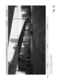
- Fig. 26 (top left) shows an example image from the collected data.
- Fig. 26 shows an example image from the collected data.
- frames that are at least 1m apart according GPS are included.
- the recorded data is split into sequences of 200m in length.
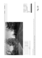
- Fig. 25 shows an example road image (top left), including annotations for road (top right), ego-lane (bottom left) and lane instance (bottom right).
- Road and lanes below vehicles are annotated despite being occluded.
- Non-coloured parts have not been annotated, i.e. the class is not known.
- FIG 3 shows a simplified block diagram of a vehicle 300 that can be used to capture road images to be annotated, that is, road images of the kind described above with reference to Figure 1 .
- these images are captured as frames of short video segments recorded as the vehicle 300 drives along a road, in such a way as to allow the path travelled by the vehicle during the recording of each video segment to be reconstructed from the frames of that segment.
- the vehicle 300 may be referred to as a training vehicle, as a convenient shorthand to distinguish it from the autonomous vehicle 200 of Figure 2 .
- the training vehicle 300 is shown to comprise an image capture device 302, which can be a forward-facing or rear-facing image capture device, and which is coupled to a processor 304.
- the processor 304 receives the captured images from the image capture device 302, and stores them in a memory 306, from which they can be retrieved for use in the manner described below.
- the vehicle 300 is a car in this example, but it can be any form of vehicle.
- Underpinning the invention is an assumption that the path travelled by the human-driven training vehicle 300 extends along a road, and that the location of the road can therefore be inferred from whatever path the training vehicle 300 took.
- it comes to annotating a particular image in the captured sequence of training images, it is the hindsight of the path that the training vehicle 300 subsequently took after that image was captured that allows the automatic annotation to be made.
- hindsight of the vehicle's behavior after that image was captured is exploited in order to infer the location of the road within the image.
- the annotated road location is thus a road location that is expected given the path subsequently travelled by the training vehicle 300 and the underlying assumptions about how this relates to the location of the road.
- the path is determined by processing the captured images themselves. Accordingly, when annotating a particular image with an expected road location, for a forward-facing (resp. rear-facing) image capture device 302, the expected road location in that image is determined from the path travelled by the vehicle after (resp. before) that image was captured, as reconstructed using at least one of the subsequently (resp. previously) captured images in the sequence of captured images. That is, each image that is annotated is annotated using path information derived from one or more of the images captured after (resp. before) the image being annotated.
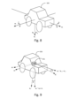
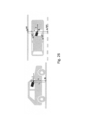
- Fig. 27 shows the principles of the estimation of the lane border points at frame i.
- c i is the camera position at frame i (obtained via SfM)
- f is the forward direction
- n is the normal vector of the road plane (both relative to the camera orientation)
- h is the height of the camera above the road
- r is the horizontal vector across the lane and are the distances to the left and right ego-lane borders.
- the initial annotation step is automated and provides an estimate of the road surface in 3D space, along with an estimate for the ego-lane (see Sec. 3.1). Then the estimates are corrected manually and further annotations are added in road surface space. The labels are then projected into the 2D camera views, allowing the annotation of all images in the sequence at once (see Sec. 3.2).
- first OpenSfM [28] - a" structure-from-motion" algorithm - is applied to obtain the 3D camera locations c i and poses R i for each frame i ⁇ ⁇ 1, ..., N ⁇ in a global coordinate system, as well as the camera focal length and distortion parameters.
- the road is assumed to be a 2D manifold embedded in the 3D world. Furthermore, the local curvature of the road is low, and thus the orientation of the vehicle wheels provide a good estimate of the local surface gradient.
- the camera is fixed within the vehicle with a static translation and rotation from the current road plane (i.e. it is assumed the vehicle body follows the road plane and neglect suspension movement). Thus the ground point g i on the road below the camera at frame i can be calculated as
- h is the height of the camera above the road and n is the surface normal of the road relative to the camera (see Fig. 26 , left).
- the left and right ego-lane borders can then be derived as where r is the vector within the road plane, that is perpendicular to the driving direction and are the offsets to the left and right ego-lane borders. See Fig. 26 (right) for an illustration.
- a simplifying assumption is made that the road surface is flat perpendicular to the direction of the car motion (but there is no assumption that the road is flat generally - if the ego path travels over hills, this is captured in the ego path).
- the lane annotations can be drawn as polygons of neighbouring future frames, i.e. with the corner points
- the camera height above the road ft is easy to measure manually. However, in case this cannot be done (e.g. for dash-cam videos downloaded from the web) it is also possible to obtain the height of the camera using the estimated mesh of the road surface obtained from OpenSfM. A rough estimate for h is sufficient, since it is corrected via manual annotation, see the following section.
- Fig. 27 shows the principles of the estimation of the road normal n and forward direction f i at a single frame i.
- the final estimate is an aggregate over all frames.
- the road normal n is estimated based on the fact that, when the car moves around a turn, the vectors representing it's motion m will all lie in the road plane, and thus taking the cross product of them will result in the road normal, see Fig. 27 .
- n i R i ⁇ 1 m i ⁇ 1 , i ⁇ m i , i + 1 , where ⁇ denotes the cross-product (see Fig. 27 ).
- ⁇ denotes the cross-product (see Fig. 27 ).
- the quality of this estimate depends highly on the degree of the previous assumptions being correct.
- the movements are weighted according the inner product in order to up-weight parts with a low rate of turn, while the max assures forward movement.
- the quantities w i left and w i right are important to get the correct alignment of the annotated lane borders with the visible boundary.
- the ego-lane has a fixed width w
- a sequence is selected with a many turns within the road plane to estimate n and a straight sequence to estimate f . Then the same values are re-used for all sequences with the same static camera position. Only the first part of the sequence is annotated, up until 100m from the end, since otherwise not sufficient future lane border points can be projected.
- Annex A Algorithm 1
- a visualisation of the automated border point estimation is shown in Fig. 28 (see below) and labelled as such.
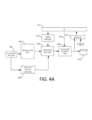
- Figure 4 shows a schematic block diagram of an image processing system which operates in accordance with the present invention so as to automatically generate annotation data for training images captured in the manner described above with reference to Figure 3 .
- the annotation data marks expected road locations within the images, where those locations are inferred using the aforementioned assumptions.
- Figure 4A shows an extension of this system, which is described below.
- the system of Figure 4A includes all of the components of Figure 4 , and all description of Figure 4A applies equally to Figure 4A .
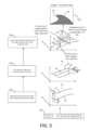
- Figure 5 shows on the left hand side a flowchart for the automatic image annotation process implemented by the image capture system, and on the right hand side an example illustration of the corresponding steps.
- the image processing system of Figure 4 is shown to comprise a path reconstruction component 402, a road modelling component 404 and an image annotation component 406.
- the path reconstruction component 402 receives a sequence of captured two-dimensional (2D) images 400 and processes them to create a three-dimensional (3D) reconstruction of the path travelled by the vehicle from the captured sequence of images (Step 502, Figure 5 ).
- Figure 5 shows two reconstructed paths in three-dimensional space.
- the first path is a 3D reconstruction of the path travelled by the image capture device (camera) 302 of the training vehicle 300.
- Techniques for reconstructing the path travelled by a moving camera from a sequence of images captured by the camera as it moves are known in the art, and are therefore not described in detail herein.
- the second path is a reconstruction of the path travelled by the training vehicle 300, which is defined as the path travelled by a point that lies approximately half way across the width of the training vehicle 300, i.e. equidistant from the right-hand and left-hand sides of the training vehicle, and below the image capture device 300 at approximately road level (labelled P in Figures 3 and 3A ). That is, at road height and along a center-line (C, Figure 3A ) of the vehicle 300 that extends vertically and lies at the halfway point along the width of the vehicle 300.
- the road modelling component 404 creates a 3D model (602, Figure 6 ) of the road the vehicle is assumed to have travelled along (Step 504, Figure 5 ).
- the road model is formed of two geometric curves R1, R2, corresponding to assumed lane boundary locations, which are defined as lying parallel to, and at the same height as, the vehicle path VP, on either side of the vehicle path VP and each at a distance W/2 from it, where W is an assumed road or lane width.
- the expected road locations can for example correspond to an edge of the road itself (so as to mark the road, or the non-drivable area beside the road), or to lane locations of lanes within the road.
- the automated annotation techniques can be used to mark the locations of what is referred to herein as "parallel structure", i.e. structure that is expected to run at least approximately parallel to the path driven by the vehicle, or more generally to expected structure that is expected to have a specific orientation relative to the vehicle path.
- This can be road structure such as roads, lanes, non-drivable areas assumed to lie parallel to the vehicle path, junctions assumed to extend perpendicular to the vehicle path, or real-world parallel structures that might be encountered by vehicles other than cars, such as runways (in the case of autonomous drones, planes etc.) etc.
- all description of the 3D road model applies equally to any other form 3D structure model of an environment in which the vehicle travelled, for which expected parallel structure can be automatically determined using the methods described herein.
- the description may make specific reference to roads or lanes, and to related parameters such as road or lane width.
- road or lane width may be any parallel road structure, and that any references to road or lane width (and the like) apply generally to a width parameter determined for the expected parallel structure.
- the 3D road model is used by the image annotation component 406 to generate 2D annotation data for marking the individual 2D training images individually with expected road locations (Step 506, Figure 5 ).
- the annotation data A(n) for the nth 2D image in the sequence is generated by performing a geometric projection of the 3D road model onto the plane of that image, labelled l(n).
- the image plane l(n) is a plane corresponding to the field of view of the camera 302 when image n was captured, and is thus located at a point corresponding to the location of the vehicle when image n was captured.
- a parameter computation component 408 computes various "reference parameters" that are used to construct the 3D model from the reconstructed vehicle path and to perform the geometric projection. These reference parameters comprise the following image capture parameters, relating to the position and orientation of the image capture device 302 of the training vehicle 300:
- the annotation data is stored in electronic storage 414, from which it can be accessed or retrieved for use in the training process described above with reference to Figure 1 .
- the automatic structure detection component 102 is learning from the human driver's ability to keep the vehicle 300 in approximately the center of the road most of the time whilst the training images are captured.
- An annotation interface provides a human annotator with the ability to view the frames in a batch individually with the currently rendered lanes projected into the images. These lanes can be widened, narrowed and moved by the annotator in the most convenient frame and these changes to the lane structure will be projected into all other frames in the batch, providing a clear advantage over annotation of all of the image individually.
- Fig. 28 shows a Visualisation of the ego-lane estimate, seen from above.
- the automated estimate is and manual correction are labelled, respectively, as
- the annotators correct the w i left and w i right , after which the estimate improves.
- Figures 18 to 24 shows examples of the annotation interface used by the annotators.
- the ego-path can be seen projected into this frame.
- the annotator is provided with controls to manipulate currently rendered lanes (narrow, widen, move to the left or right, move the boundaries of the lane etc.) and add new lanes.
- the annotator is provided with means to adjust the camera height, to match the reconstruction to the road surface, and the crop height, to exclude the vehicles dash or bonnet. All annotations are performed in the estimated 3D road plane, but immediate feedback is provided via projection in the 2D camera view. The annotator can easily skip forward and backward in the sequence to determine if the labels align with the image, and correct them if needed. An example of a corrected sequence is shown in Fig. 27 (see above).
- a strip along the side of road denoted by reference sign NR1
- a strip along the side of road denoted by reference sign NR1
- a strip along the side of road denoted by reference sign NR2
- the whole upper part of each image is annotated as non-road, where the size is adjusted manually by the annotators.
- Fig. 25 shows an example of the rendered annotations.
- a rendering component 416 which can render, via a user interface (Ul) 412, an individual training image (img n) marked with the expected road annotations determined for that image.
- a user can check how closely the expected road structure corresponds to the actual road structure visible in the image, and make corrections where necessary.
- An output of the UI 412 is shown connected to an input of the image annotation component, via connector 418, to denote the fact that the user can modify the annotation data A(n) for an individual image via the UI 412, in order to better align the assumed lane boundaries R1, R2 with the actual lane boundaries in that image (only). This can be useful for accommodating "one-off" discrepancies, caused for example by unusual localized road structure.
- a model adaptation component 410 is also provided to allow efficient manual adaptation of the annotation data via the Ul 412 across multiple images simultaneously. This works by allowing the user to adapt the 3D road model with reference to a single image and its rendered annotation data, in order to better align the road boundaries in that image. However, because the 3D road model is being adapted (rather than just the individual image's annotation data A(n)), these adaptations can also be applied to the annotation data for other images, without the user having to manually adapt the annotation data for those other images. For example, a user can adjust the assumed lane width W to better fit one image, and because the road model is being adapted to the new lane width, the annotation data for other images can be automatically adapted based on the adapted model with the new lane width W. This is described in further detail below with reference to Figure 6 .
- the above-described components of the image processing system of Figures 4 and 4A are functional components of the image processing system representing functions performed by the image processing system. These functions are implemented in software, that is by executable instructions (code) that are stored in memory and executed by a processor or processors of the image processing system (not shown), which can be formed of one or more general purpose processing units (such as CPUs), more specialized processing units (such as GPUs) or any combination thereof. As will be appreciated, these components represent high-level functions, which can be implemented using a variety of code structures.
- the arrows in Figure 4 generally denote high-level interrelationships between these high-level functions, and do not necessarily correspond to any specific arrangement of physical or logical connections.
- the steps of Figure 5 are computer-implemented steps, which the instructions cause the image processing system to perform when executed on the one or more processors.
- FIG. 13 An example of an annotated image is shown in Figure 13 .
- two drivable lanes are marked: the ego lane towards the middle of the image, and another drivable lane to the left of the image.
- Two non-drivable regions are marked either side of those lanes, as is a lane for traffic travelling in the other direction on the far right, separated from the ego lane by one of the non-drivable areas.
- Preferred embodiments of the invention achieve this with low cost equipment, as explained later.
- the image processing techniques described below allow all the above to be determined with inexpensive and un-calibrated equipment, such as a mobile phone or a dash-cam costing a few hundred pounds, or other low cost consumer equipment. This is because they can be computed from the images captured by the training vehicle 300, using the image processing techniques described below. 3)
- the 3D path of the camera CP can be deduced by post processing captured videos from un-calibrated cameras using existing visual SLAM (simultaneous localization and mapping) techniques.
- Software packages such as OpenSFM and ORB-SLAM can be used to generate accurate camera path information.
- Such techniques can be used to construct a 3D map of the environment travelled by the training vehicle 300, whilst simultaneously tracking the vehicles' location within that environment.
- FIG. 7 shows three captured images - img(n-1), img(n) and img(n+1) - of a real-world environment, at different times and from different but near-by locations.
- triangulation can then be used to construct a 3D model of those features, as illustrated in the lower part of Figure 7 .
- a 3D location of the camera 302 at the time that image was captured - labelled x n -1 , x n , x n +1 respectively - is estimated, as is an orientation of the camera's field of view within 3D space.
- a respective image plane l(n-1), l(n), l(n+1) is defined as a plane normal to and intersecting the camera's filed of view when that image was captured, at an arbitrary non-zero distance from the camera location x n -1 , , x n +1 .
- the camera locations and orientations are selected based on ray-tracing principles applied to the reference features F1 and F2, such that for each of the camera locations x n -1 , , x n +1 , the rays (straight lines) from each of the references features F1, F2 to that camera location intersect the corresponding image plane l(n-1), l(n), l(n+1) at locations that at least approximately correspond to the locations at which that reference feature appears in the corresponding images, i.e. that feature's pixel location within the images.
- the camera path CP can then be reconstructed from the resulting sequence of camera locations x n -1 , x n , x n +1 .
- this 3D model constructed as part of the SLAM process is distinct from the 3D model constructed by the modelling component 404.
- the former is in the form of a surface map constructed based on image triangulation, whereas the later represents expected structure that is inferred based on the vehicle path, which in turn is determined from the image capture device locations derived in performing the SLAM process.
- the 3D orientation of the camera 302 can be represented using pitch (P'), roll (R') and yaw (Y') angles.
- a longitudinal axis a L ' can be conveniently defined as parallel the camera's optical axis, with transverse and vertical axes a T ′ , a V ' corresponding to the horizontal and vertical orientations within the image plane (i.e. to the directions that appear as horizontal and vertical in the captured images), with the camera's pitch P', roll R' and yaw Y' defined as angles about the camera's transverse, longitudinal and vertical axes a T ′ a L ′ , a V ' (camera axes), respectively.
- Such SLAM techniques do in fact generate surface reconstructions of the environment. Whilst such surface reconstructions could be used be used to determine road/lane positions directly in theory, generally the quality of the surface reconstructions is not sufficient to do so in practice. However, the quality of the motion of the camera through the 3D scene is good, and thus provides a sufficiently accurate reconstruction of the camera path CP (this is because the camera positions are based on order hundreds of feature points where as surface positions are only based on a handful of feature points), which in turn allows the road/lane positions to be inferred using the present techniques, with sufficient accuracy.
- FIG. 14 An example image of an SLAM reconstruction of camera positions moving through a point cloud world is shown in Figure 14 .
- the sequence of pyramid structures labelled 1400 represent the locations and orientation of the image capture device when the different images were taken, as estimated via the SLAM process. Collectively these define the camera path CP.
- the blocks labelled 1402 constitute a 3D surface map generated as part of the SLAM process. Both of these aspects are described in further detail later.
- the remaining reference parameters are computed by the parameter computation component 408 via image processing, as described below. First some of the underlying considerations are briefly introduced.
- the 3D orientation of the training vehicle 300 can be defined in the same way as the camera.
- the vehicle's pitch, roll and yaw are labelled P, R and Y respectively
- the training vehicle's transverse, longitudinal and vertical axes are represented by unit vectors a T, a L , a V respectively.
- the longitudinal axis corresponds to the direction in which the vehicle travels when travelling in a straight line (forward direction).
- the vertical axis is the direction normal to the road surface (that is, to the plane in which the contact points between the vehicle's wheels and the road lie).
- the transverse axis runs along the width of the vehicle 300, perpendicular to the longitudinal and vertical axes.
- absolute herein is used herein to refer to orientation and locations within the environment in which the vehicle is travelling. That is, as defined relative to an (arbitrary) global coordinate system of a global frame of reference of the environment in which the vehicle moves. This can be defined as an inherent part of the SLAM process. This is the coordinate system in which the reconstructed vehicle path, the orientation of the image capture device within the environment (absolute orientation) and the surface reconstruction are defined.
- relative is used to refer to locations and orientations relative to the vehicle, that is, defined relative to a coordinate system of the vehicle, such as the coordinate system defined by the vehicle axes a T , a L , a V .
- the method does not require the orientation of camera 302 to be perfectly aligned with the orientation of the training vehicle 300.
- Angular misalignment of the camera axes relative to the vehicle axes is acceptable, because this misalignment can be detected and accounted for using the techniques described below.
- the angular orientation of the camera within the car - i.e., the angular offset between the camera's longitudinal axis a L ' and the vehicle's longitudinal axis a L (that is, the vehicle's longitudinal axis a L as measured within a frame of reference of the image capture device, i.e.
- the vector difference x t +1 - x t -1 lies approximately parallel to the vehicles longitudinal axis so long as the rate of turn is approximately constant (it doesn't actually require the vehicle to be travelling in a straight line). However the assumption of approximate constant rate of turn will be more likely to be true when the vehicle is more closely travelling in a straight line.
- the calculation is performed as a vector average, in which the vector that represents the average forward motion of the car as expressed in the camera coordinate system. This vector when projected forwards will cut the image plane at a specific pixel (the forward point pixel). This pixel is the point which the car would seem to be moving towards if it were driving on a perfectly straight and flat road (the "forward point” as that term is used herein).
- the longitudinal vehicle axis a L at time t is assumed to lie parallel to the vector difference x t +1 - x t -1 .
- x t +1 - x t -1 needs to be evaluated in the reference frame of the image capture device 302 in this context, in order to give meaningful results, i.e. in order for the weighted average of equation (1) to provide an accurate estimate of the direction of the vehicle's longitudinal axis a L relative to the camera's longitudinal axis a L ′ .
- the SLAM process will derive absolute values for x t +1 and x t -1 , i.e. in the global coordinate system.
- the direction of the camera axes in the global coordinate system, i.e. the absolute orientation of the image capture device, at time t is also derived via the SLAM process itself, which can in turn be used to transform vectors in the global frame of reference into the frame of reference of the image capture device 302.
- the dot product v 0 ⁇ v 1 depends on the magnitude of the change in direction between t-1 and t+1, such that the smaller the change in the magnitude of direction, the greater weighting that is given to the measurement at time t.
- the vector difference x t +1 - x t -1 lies approximately parallel to the vehicles longitudinal axis so long as the rate of turn is approximately constant (it doesn't actually require the vehicle to be travelling in a straight line). Therefore an alternative weighting scheme could be used in which the vector difference at each time is weighted according to the change in curvature exhibited in the vehicle path between t-1 and t+1.
- the orientation of the vehicle's axes remains fixed in the image capture device's frame of reference as the vehicle moves, because the camera 302 is expected to remain in an essentially fixed orientation relative to the vehicle 300 - the time dependency in the above stems from the fact that the estimates of the vehicle and camera axes are not exact.
- Time t corresponds to a certain point on the camera path CP, and can be a time at which one of the images was captured or a time in between captured images, to which a camera pose can be assigned by interpolation of the camera poses for different images.
- the offset between a L and a L ' could be represented as a pair of angles.
- the rotational offset between the camera's vertical axis a V ' and the vehicle's vertical axis a V can be automatically deduced by noting that most roads are locally flat and so when the car is in a turn, the vector that is perpendicular to the surface described by the camera path will point directly downwards from the camera to the road surface.
- the cross product of the two vectors from the centre to the two outer points is taken and that is continuously averaged weighted by the magnitude of the cross product.
- the average normal vector of the path expressed in camera coordinates.
- the plane that is perpendicular to this road surface normal vector can be intercepted with the image plane and this will provide a line across the image that would match the horizon if the car were driving along a perfectly straight and level road (the "horizon line” as that term is used herein).
- the rotational orientation of the camera within the vehicle can be computed as a weighted average of the offset angle between the vertical axes of the camera and vehicle respectively according to the equation (2): ⁇ t w V , t v 0 ⁇ v 1 ⁇ t w V , t where:
- the vertical vehicle axis a V at time t is assumed to lie parallel to the vector cross product v 0 ⁇ v 1 .
- v 0 ⁇ v 1 needs to be evaluated in the reference frame of the image capture device 302 in this context, in order to give meaningful results, i.e. in order for the weighted average of equation (s) to provide an accurate estimate of the direction of the vehicle's vertical axis a V relative to the camera's longitudinal axis a L ′ .
- the absolute orientation of the image capture device as determined via the SLAM process can be used to transform vectors from the global frame of reference into the frame of reference of the image capture device.
- the height of the camera above the road can be calculated by generating a surface mesh of the road from the SLAM process (even though this is low accuracy) and then averaging the height of all points on the camera path above this mesh. The averaging across the whole path counteracts the poor accuracy of the mesh generated by the SLAM process.
- the height H at a given point on the camera path CP is defined the distance between a point on the camera path CP and the mesh along the vehicle's vertical axis a V at that point.
- a reason the rotational orientation of the camera 302 within the vehicle 300 is needed is to determine where the vehicle's vertical axis lies at each point on the path so that the height estimation can be computed. This is illustrated in Figure 11 , in which the reconstructed surface map is labelled SM. 7)
- the left to right position of the camera (S) within the lane and also the width of the lane (W) can be estimated by using various computer vision techniques to detect the lane boundaries.
- Detecting the lane edges is obviously a hard problem (and the whole purpose of generating this lane training data is to train a neural network to solve this problem).
- detecting lane edges in this specific case can be made into a significantly easier problem by virtue of having two additional pieces of information. Firstly, the known path of the camera (and thus shape of the lane) can be used to create a transform to effectively straighten out the road prior to doing any lane boundary detection. Secondly the positions at which to search for lane boundaries are significantly reduced because the centre line of the lane is (nearly) known from the camera path and lanes have widths that are relatively fixed.
- the images can be projected into a top down view, transformed to straighten out the road (using the camera path information) and then a Hough transform can be used to detect dominant lines with the correct approximate position and orientation.
- the width of the road at each point on the camera path CP is defined as the distance between the detected lane boundaries along the transverse vehicle axis a T at that point.
- a reason the angular orientation of the camera 302 within the training vehicle 300 is needed in addition to the rotational orientation is to determine where the vehicle's transverse axis a T lies in order to estimate W and C at each point along the path. This is also illustrated in Figure 11 .
- Figure 17 shows an image of a SLAM reconstruction of camera positions moving through a point cloud world, where there are two sets of camera images. 9) It is difficult to merge images from multiple videos into a single 3D reconstruction unless the camera images are all facing the same direction; i.e. it is not practical to merge videos of cars driving in opposite directions along the road into a single 3D reconstruction.
- One way to solve this is to drive in one direction with a forward-facing camera, and drive in the other direction (on the other lane) using a backwards-facing camera. This gives a single set of images all pointing in the same direction along the road.
- This efficient saving stems from the fact that the user can adapt the 3D road model (via the model adaptation component 410) using one frame and its annotation data as a reference, and the fact that the adapted 3D road model can in turn can be applied to multiple images.
- the technology is not limited to manual adjustment of automatically generated road/lane models. Any object in the world that is stationary can be marked and that object's position in each image of the video can be calculated (since the motion of the camera is known).
- Figure 6 shows a schematic block diagram that illustrates an example of the types of adjustment that can be performed at the human fixer stage.
- the rendering component can render data of any one of the captured images on a display of the user interface 412, overlaid with its associated annotation data A(n).
- One or more selectable options 600 are also rendered, which a user can select in order to cause the model adaptation component 410 to adapt the 3D road model 602, in a fast and intuitive manner.
- the road model 602 is updated, not only is the annotation data A(n) that is currently being rendered modified in accordance with the adapted model 602, but the adapted model 602 can also be used to update the annotation data 604 for other images in the same video sequence.
- the top part of Figure 6 shows a marked road or lane within an image.
- the right-hand side boundary R2 accurately coincides with a real-world right-side boundary visible in the image
- the left-side boundary R1 is slightly off.
- the user can fix this quickly by shifting the position of the left-side boundary in the 3D model, using the current image and the annotation data rendered on the current image as a reference to manually adapt the location of the left-side boundary R2 until it corresponds with a real-world left-side boundary visible in the image.
- This change will apply across multiple images in the sequence, meaning that the left-side road boundary will be accurately placed in those images for as long as the road/lane remains the same width.
- the user starts at the beginning of a training sequence.
- the 3D ego-lane has been automatically determined using the techniques above.
- the locations of the centre and left/right lane markers have been determined, by assuming these are of a certain width and lie at the centre and far right/far left of the ego lane.
- the user can adapt the ego lane width and position, and also the width and position of the road markings if necessary, to align them with the actual ego lane/road markings visible in the image.
- the user can also add additional parallel structure at this point, such as non-ego lanes, non-driveable areas etc.
- FIG 18 An example of an automatically annotated image, pre-fix up is shown in Figure 18 , in which only the ego lane (and its assumed centre line and lane boundaries) are marked. As can be seen, the markings do not exactly line with the actual lane boundaries.
- Figure 19 shown the image after a fix up, where the width and position of the ego-lane has been adjusted, and the other lanes and non-drivable regions have been marked.
- Non-drivable road structure at the edges of the road will be automatically adapted to accommodate the parallel junction (i.e. any part of the non-drivable road structure that overlaps with the new junction will be removed automatically).
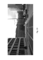
- FIG. 22 An example of the Ul when a junction has just been added is shown in Figure 22 .
- the user has defined the junction as cutting through the left and right lanes, perpendicular to the lanes.
- the user gets to a point in the video at which the road/lane width changes (e.g. lane narrows/widens, the number of lanes changes or is reduced etc.), s/he can split the video at that point and modify the underlying model using that frame as a reference (step 1, Figure 12 ).
- the location of the current video frame is mapped to a point on the vehicle path, which in turn is used to restrict adaptations of the 3D model to the part of the model after that point only - points before that (where the user has already verified that the annotations match the images) are unaffected.
- the user can change the road width, add a lane etc.
- the system is capable of automatically interpolating parallel structure around split points, e.g.
- Figures 23 and 24 show an example of this.
- the user has selected the option to split the video shortly after the junction of Figure 22 , to accommodate the fact that there is now a wider non-drivable region of road on the right hand side, which the user has annotated accordingly in Figure 24 .
- the user can also mark an area of sky in the images. This can be a simple case of the user defining a sky line, above which all of the images are definitely sky. Even though this will not label all of the sky in the images, this can still be useful in preventing the trained neural network from identifying sky as road structure. More sophisticated techniques could use the 3D road structure to infer a sky line in each image, e.g. based on the highest point of the road in 3D space.
- the road markings can be annotated in this way. Both in position and type. Including centre dashed or solid lines, road edge lines, double yellow lines etc. For example, cycle lanes can be added in this way, as can pavements.
- Figure 20 shows an example of an image in which a cycle lane is marked, to the left-hand side.
- Any feature in the video stationary in the world can benefit from some level of speed up. Even if they cannot directly be created as a result of their shape being parallel to the path driven, they can still benefit from the fact that they can be marked up by a human in one frame of the video and automatically propagated through to all frames of the video. 13)For example, road signs can be annotated in this way. The sign can be specifically marked out by a human in one frame (with or without any initial hint provided by a poor-quality detection) and then automatically propagated though the entire set of images in the video.
- Annotation for stationary vehicles can be generated in this same way.
- the technique does not automatically allow annotation of moving objects to be sped up in the same way, the technique can be used for parked vehicles.
- Moving vehicles could be annotated by marking the same object in multiple (at least two) images and assuming constant speed in-between the annotations. Then the label can be propagated to all images in-between the annotated ones. 14)Note that vehicles that are stationary look just the same as vehicles that are moving, so a neural network trained on annotated images of stationary vehicles, can be used at run time to detect moving vehicles.
- Figure 21 shown an image in which a 3D bounding box of a vehicle is being added.
- Another benefit of this technique is that the human can choose to annotate an object in an image in the video when the camera is close to it (i.e. when the object is large). This accurate annotation is then propagated to all images even when the object is small within the image. 15)Since there is a 3D model underlying the whole sequence of images in the video, then annotations automatically generated when the object is more distant from the camera will have the accuracy of annotation when the object was large and annotated by a human. This can often be more accurate than could be achieved by a human trying to annotate the small image of the object.
- the trained road detection component 102 has a number of useful applications within an autonomous vehicle 200.
- Predetermined road map data refers to data or a road map or maps that have been created in advance, of the kind currently used in GPS-based navigation units (such as smartphones or "satnavs”) and the like.
- road structure identified by the trained road detection component 102 can be used to more accurately pinpoint the vehicle's location on a road map. This works by matching the road structure identified via machine vision with corresponding road structure of the predetermined map.
- the location of the autonomous vehicle 200 relative to the identified road structure can be determined in three-dimensions using a pair of stereoscopically arranged image capture devices, for example, which in turn can be used to determine the location of the autonomous vehicle on the road map relative to the corresponding road structure on the map.
- Another such application merges the visually-identified road structure with corresponding road structure of the road map.
- the road map could be used to resolve uncertainty about visual road structure detected in the images (e.g. distant or somewhat obscured visual structure).
- the confidence of the structure detection can be increased.
- Table 1 provides a comparison of the method of this disclosure with prior art benchmarks, identified in the References section below. Table 1. Comparison of the available datasets. Label time per image is only shown if provided by the authors. Name Year #labeled frames #videos img. seq. road area ego lane lane instances label time per img.
- Table 2(a) shows a breakdown of the included annotation types. In total, there were 47,497 lane instances annotated, i.e. 118.2 per sequence. Instance IDs are consistent across a sequence, i.e. consecutive frames will use the same instance ID for the same lane. Furthermore, the annotators were instructed to categorise each sequence according the scene type: urban, highway or rural. The breakdown of the sequences is shown in Table 2(b).
- the data was split into two sets, for training and testing.
- the train set comprises 360 sequences and a total of 21,355 frames, while the test set includes 42 sequences and 2,624 frames.
- the test set was selected to include the same urban/motorway/rural distribution as the train set.
- the frames of the training set are made available with both images and annotations while only the images are provided for the testing set.
- the annotation quality is measured through agreement between the two annotators on twelve randomly selected sequences. 84.3% of the pixels have been given a label by at least 1 annotator, with 67.3% of these being given an annotation by both annotators; i.e. 56.8% of all pixels were given an annotation by both annotators.
- the agreement on these overlapping labels is measured via Intersection-over-Union (IoU).
- the results are shown in Table 4. The standard deviation is calculated over the 12 sequences. Table 3. Measured average annotation time in seconds. Scene type Urban Highway Rural Per sequence 381 100 140 Per image 5 2 2 Table 4. Agreement of the annotators measured by IoU. Task IoU std Road vs non-road 97.2 ⁇ 1.5 Ego-Lane vs road va non-road 94.3 ⁇ 3.4 A P@50 AP Lane instance segmentation 99.0 84.4
- each input image was reprocessed by resizing it to have a height of 330px and extracting a random crop of 320x320px; the crops were selected randomly each time an image was selected to be involved in a minibatch.
- ADAM was used with a learning rate of 0.001 which is decayed to 0.0005 after 25000 steps and then to 0.0001 after 50000 steps. The training was performed for 100,000 training steps, reporting results on the model which converges on the validation set. A mini batch size of two was used and the optimisation was performed on a per pixel cross entropy loss.
- SegNet models were trained following the above configuration. Models were trained on the training set, CityScapes coarse, Mapillary and KITTI Lanes. A Road/Non-Road model was trained for all datasets, but Ego/Non-Ego/Non-Road was trained for the UM portion of KITTI Lanes and the present dataset.
- the IoU and the FI score are provided.
- Each model is measured on held out data from every dataset.
- the held out set is the pre-defined validation set of both datasets, for the present dataset the held out set is the corresponding test set.
- the exception to this scheme is KITTI Lanes which has no available annotated held out set and reducing KITTFs size further by holding out a validation set would reduce the size of an already small dataset making results more difficult to interpret. Therefore, the entire KITTI training set is targeted by models Mapillary and CityScapes.
- IoU and FI are measured for each class for each task and an average across classes for each task is provided. These results can be seen in Tables 5 and 6.
- the rest of the analysis concerns the results achieved by models trained on data outside the target evaluation dataset (i.e. the off diagonals in the results tables).
- the least populous dataset KITTI Lanes2 achieves the worst IoU across all tasks.
- Cityscapes is the next largest dataset3 and achieves the next highest IoU across most tasks and finally Mapillary, the dataset most similar in size to the present dataset, achieves the next highest IoU while still performing significantly worse than the present methods own across all tasks.
- the AP measures were used calculated as per the MS-COCO instance segmentation task. Specifically: calculate the average precision across images and across loU thresholds of detected lanes (pixels assigned to embedding cluster centroids) and ground truth lanes. A detection is a true positive when it overlaps a ground truth instance with an IoU above some threshold. A ground truth is a false negative when it has no lanes assigned to it in this way and a detection is a false positive when it does not sufficiently overlap any ground truth instance. Using these definitions, an average precision at 50% IoU and an average AP across multiple thresholds from 50% to 95% in increments of 5% was obtained as set out in Table 7.
- Non-parallel lanes could be handled by extending the annotator tool to allow for variable angles for the lanes in the road plane. Furthermore, the position of dynamic objects could be estimated by including additional modalities, like stereo vision or lidar.
Landscapes
- Engineering & Computer Science (AREA)
- Physics & Mathematics (AREA)
- General Physics & Mathematics (AREA)
- Theoretical Computer Science (AREA)
- Radar, Positioning & Navigation (AREA)
- Remote Sensing (AREA)
- Computer Vision & Pattern Recognition (AREA)
- Multimedia (AREA)
- Automation & Control Theory (AREA)
- Evolutionary Computation (AREA)
- Software Systems (AREA)
- Artificial Intelligence (AREA)
- Data Mining & Analysis (AREA)
- Computing Systems (AREA)
- Databases & Information Systems (AREA)
- General Health & Medical Sciences (AREA)
- Medical Informatics (AREA)
- Health & Medical Sciences (AREA)
- Mechanical Engineering (AREA)
- Human Computer Interaction (AREA)
- Transportation (AREA)
- Bioinformatics & Cheminformatics (AREA)
- Bioinformatics & Computational Biology (AREA)
- Evolutionary Biology (AREA)
- General Engineering & Computer Science (AREA)
- Life Sciences & Earth Sciences (AREA)
- Image Analysis (AREA)
- Image Processing (AREA)
- Traffic Control Systems (AREA)
- Navigation (AREA)
Claims (9)
- Computerimplementiertes Verfahren zum Kommentieren von Straßenszenenbildern (104), wobei das Verfahren ein Implementieren, an einem Bildverarbeitungssystem, der folgenden Schritte aufweist:Empfangen einer zeitlichen Abfolge von zweidimensionalen Bildern (104), wie sie von einer Bilderfassungsvorrichtung (202) eines fahrenden Fahrzeugs (300) aufgenommen wurden;Verarbeiten der Bilder (104), um im dreidimensionalen Raum einen vom Fahrzeug (300) zurückgelegten Weg zu rekonstruieren;Verwenden des rekonstruierten Fahrzeugwegs, um im dreidimensionalen Raum eine erwartete Straßenstruktur zu bestimmen, die sich entlang des rekonstruierten Fahrzeugwegs erstreckt; undErzeugen von Straßenanmerkungsdaten (106) zum Markieren wenigstens eines der Bilder (104) mit einer erwarteten Straßenstrukturposition, durch Durchführen einer geometrischen Projektion der erwarteten Straßenstruktur im dreidimensionalen Raum auf eine zweidimensionale Ebene dieses Bildes (104);dadurch gekennzeichnet, dass die erwartete Straßenstruktur bestimmt wird basierend auf:i) einem Straßennormalvektor n, der aus den Bildern (104) geschätzt wird als:

 ii) ein Vorwärtsrichtungsvektor, der aus den Bildern (104) geschätzt wird als:wobei Ri eine Kamerapose ist, die für das Bild i bei der Rekonstruktion des Fahrzeugwegs bestimmt wird, wobei mi,j ein normalisierter Bewegungsvektor zwischen den Rahmen i und j ist;

 wobei f und n verwendet werden, um Grenzpunkte der erwarteten Straßenstruktur zu bestimmen, als:

 wobei Ri eine Kamerapose ist, die für das Bild i bei der Rekonstruktion des Fahrzeugwegs bestimmt wird, wobei gi ein Straßenpunkt unterhalb der Bilderfassungsvorrichtung (202) ist, undwobei
 wobei h eine Höhe der Kamera ist und ci eine 3D-Position der Bilderfassungsvorrichtung (202) ist, die beim Rekonstruieren des Fahrzeugwegs bestimmt wird.
 - Verfahren nach Anspruch 1, wobei der Schritt des Verwendens des rekonstruierten Fahrzeugwegs zur Bestimmung der erwarteten Straßenstruktur ein Bestimmen einer erwarteten Straßenstrukturgrenze aufweist, die als eine Kurve im dreidimensionalen Raum definiert ist, die parallel zum rekonstruierten Fahrzeugweg verläuft, wobei die Straßenanmerkungsdaten (106) zum Markieren der Position der erwarteten Straßenstrukturgrenze im Bild (104) sind.
- Verfahren nach einem der vorhergehenden Ansprüche, wobei die kommentierten Straßenbilder (400) zur Benutzung beim Trainieren einer automatischen Straßenerkennungskomponente (102) für ein autonomes Fahrzeug (200) sind.
- Verfahren nach einem der vorhergehenden Ansprüche, wobei die Abstände zu den linken und rechten Rändern einer Straßenspur basierend auf ein oder mehr manuellen Breiteneinstellungseingaben bestimmt werden, wobei die manuellen Breiteneinstellungseingaben in Bezug auf ein Bild (104) empfangen werden und verwendet werden, um die erwartete Straßenstruktur zu modifizieren und die modifizierte Straßenstruktur in ein oder mehr andere der Bilder (104) zu projizieren.
- Verfahren nach einem der vorhergehenden Ansprüche, wobei der Fahrzeugweg unter Verwendung einer simultanen Lokalisierung and Kartierung (SLAM) - Verarbeitung rekonstruiert wird.
- Verfahren nach Anspruch 5, wobei wenigstens eine von einer Kamerapose Ri und einer 3D-Kameraposition ci für jedes Bild i bei Durchführen der SLAM-Verarbeitung bestimmt wird.
- Verfahren nach einem der vorhergehenden Ansprüche, wobei die Projektion basierend auf einer Höhe der Bilderfassungsvorrichtung (202) im Fahrzeug (300) durchgeführt wird, wobei die Höhe basierend auf einer durchschnittlichen Höhe eines rekonstruierten Weges der Bilderfassungsvorrichtung (202) und eines aus den Bildern (104) berechneten 3D-Straßenstrukturnetzes geschätzt wird.
- Computerprogrammprodukt, aufweisend einen Code, der auf einem computerlesbaren Speichermedium gespeicherten ist und konfiguriert ist, um, wenn er auf ein oder mehr Prozessoren (304) ausgeführt wird, das Verfahren nach einem der vorhergehenden Ansprüche zu implementieren.
- Ein Bildkommentierungssystem, aufweisend:
ein oder mehr Prozessoren (304), die konfiguriert sind, um das Verfahren nach einem der Ansprüche 1 bis 7 zu implementieren.
Priority Applications (1)
| Application Number | Priority Date | Filing Date | Title |
|---|---|---|---|
| EP22216297.6A EP4191532B1 (de) | 2018-03-14 | 2019-03-13 | Bildannotation |
Applications Claiming Priority (2)
| Application Number | Priority Date | Filing Date | Title |
|---|---|---|---|
| GBGB1804082.4A GB201804082D0 (en) | 2018-03-14 | 2018-03-14 | Image annotation |
| PCT/EP2019/056356 WO2019175286A1 (en) | 2018-03-14 | 2019-03-13 | Image annotation |
Related Child Applications (2)
| Application Number | Title | Priority Date | Filing Date |
|---|---|---|---|
| EP22216297.6A Division-Into EP4191532B1 (de) | 2018-03-14 | 2019-03-13 | Bildannotation |
| EP22216297.6A Division EP4191532B1 (de) | 2018-03-14 | 2019-03-13 | Bildannotation |
Publications (2)
| Publication Number | Publication Date |
|---|---|
| EP3735675A1 EP3735675A1 (de) | 2020-11-11 |
| EP3735675B1 true EP3735675B1 (de) | 2024-05-01 |
Family
ID=61972737
Family Applications (5)
| Application Number | Title | Priority Date | Filing Date |
|---|---|---|---|
| EP24160595.5A Pending EP4354403A3 (de) | 2018-03-14 | 2019-03-13 | Fahrzeuglokalisierung |
| EP22197780.4A Active EP4145393B1 (de) | 2018-03-14 | 2019-03-13 | Fahrzeuglokalisierung |
| EP22216297.6A Active EP4191532B1 (de) | 2018-03-14 | 2019-03-13 | Bildannotation |
| EP19712541.2A Active EP3732657B1 (de) | 2018-03-14 | 2019-03-13 | Fahrzeuglokalisierung |
| EP19711082.8A Active EP3735675B1 (de) | 2018-03-14 | 2019-03-13 | Bildannotation |
Family Applications Before (4)
| Application Number | Title | Priority Date | Filing Date |
|---|---|---|---|
| EP24160595.5A Pending EP4354403A3 (de) | 2018-03-14 | 2019-03-13 | Fahrzeuglokalisierung |
| EP22197780.4A Active EP4145393B1 (de) | 2018-03-14 | 2019-03-13 | Fahrzeuglokalisierung |
| EP22216297.6A Active EP4191532B1 (de) | 2018-03-14 | 2019-03-13 | Bildannotation |
| EP19712541.2A Active EP3732657B1 (de) | 2018-03-14 | 2019-03-13 | Fahrzeuglokalisierung |
Country Status (5)
| Country | Link |
|---|---|
| US (4) | US20210364320A1 (de) |
| EP (5) | EP4354403A3 (de) |
| CN (2) | CN111801711B (de) |
| GB (2) | GB201804082D0 (de) |
| WO (2) | WO2019175285A1 (de) |
Families Citing this family (57)
| Publication number | Priority date | Publication date | Assignee | Title |
|---|---|---|---|---|
| US11282287B2 (en) * | 2012-02-24 | 2022-03-22 | Matterport, Inc. | Employing three-dimensional (3D) data predicted from two-dimensional (2D) images using neural networks for 3D modeling applications and other applications |
| WO2019006189A1 (en) | 2017-06-29 | 2019-01-03 | Open Space Labs, Inc. | AUTOMATED SPACE INDEXING OF IMAGES BASED ON MASS PLAN CHARACTERISTICS |
| GB201804082D0 (en) | 2018-03-14 | 2018-04-25 | Five Ai Ltd | Image annotation |
| JP2019191653A (ja) * | 2018-04-18 | 2019-10-31 | アイシン・エィ・ダブリュ株式会社 | 地図情報更新システムおよび地図情報更新プログラム |
| DE102018209607A1 (de) * | 2018-06-14 | 2019-12-19 | Volkswagen Aktiengesellschaft | Verfahren und Vorrichtung zum Bestimmen einer Position eines Kraftfahrzeugs |
| CN112714913B (zh) | 2018-09-26 | 2024-11-01 | 法弗人工智能有限公司 | 结构注释 |
| CN113424131B (zh) | 2018-11-12 | 2025-11-04 | 开放空间实验室公司 | 图像到视频的自动空间索引 |
| JP7038643B2 (ja) * | 2018-11-26 | 2022-03-18 | 本田技研工業株式会社 | 映像表示装置 |
| US11170230B2 (en) * | 2019-02-26 | 2021-11-09 | Tusimple, Inc. | Method and system for map construction |
| US11308639B2 (en) * | 2019-03-12 | 2022-04-19 | Volvo Car Corporation | Tool and method for annotating a human pose in 3D point cloud data |
| CN109948712A (zh) * | 2019-03-20 | 2019-06-28 | 天津工业大学 | 一种基于改进的Mask R-CNN的纳米颗粒尺寸测量方法 |
| CN110135302B (zh) * | 2019-04-30 | 2021-08-31 | 百度在线网络技术(北京)有限公司 | 训练车道线识别模型的方法、装置、设备和存储介质 |
| US20200349468A1 (en) * | 2019-05-03 | 2020-11-05 | Apple Inc. | Data management platform for machine learning models |
| CN110619279B (zh) * | 2019-08-22 | 2023-03-17 | 天津大学 | 一种基于跟踪的路面交通标志实例分割方法 |
| US11327506B2 (en) * | 2019-11-20 | 2022-05-10 | GM Global Technology Operations LLC | Method and system for localized travel lane perception |
| CN110998663B (zh) * | 2019-11-22 | 2023-12-01 | 驭势(上海)汽车科技有限公司 | 一种仿真场景的图像生成方法、电子设备和存储介质 |
| EP4071739A4 (de) * | 2019-12-02 | 2024-01-03 | Pioneer Corporation | Informationsverarbeitungsvorrichtung, steuerungsverfahren, programm und speichermedium |
| US11189007B2 (en) * | 2019-12-03 | 2021-11-30 | Imagry (Israel) Ltd | Real-time generation of functional road maps |
| KR20210132496A (ko) * | 2020-04-27 | 2021-11-04 | 한국전자기술연구원 | 영상 기반 차선 검출 및 주행 차로 인식 방법 및 장치 |
| DE102020111659A1 (de) * | 2020-04-29 | 2021-11-04 | Car.Software Estonia As | Verfahren, System und Computerprogrammprodukt zur Bestimmung der Pose einer mobilen Einheit |
| CN111707277B (zh) * | 2020-05-22 | 2022-01-04 | 上海商汤临港智能科技有限公司 | 获取道路语义信息的方法、装置及介质 |
| GB202013100D0 (en) | 2020-08-21 | 2020-10-07 | Five Ai Ltd | Image annotation tools |
| KR102737724B1 (ko) * | 2020-08-28 | 2024-12-04 | 주식회사 에이치엘클레무브 | 자율 주행 시스템 및 자율 주행 방법 |
| JP7556406B2 (ja) * | 2020-12-03 | 2024-09-26 | 日本電気株式会社 | ライン位置推定装置、方法およびプログラム |
| CN114648712B (zh) * | 2020-12-18 | 2023-07-28 | 抖音视界有限公司 | 视频分类方法、装置、电子设备及计算机可读存储介质 |
| US11861858B2 (en) * | 2021-01-21 | 2024-01-02 | Zebra Technologies Corporation | System and method for automatic container configuration using fiducial markers |
| FR3121250A1 (fr) * | 2021-03-25 | 2022-09-30 | Airbus Helicopters | Procédé d’apprentissage d’une intelligence artificielle supervisée destinée à identifier un objet prédéterminé dans l’environnement d’un aéronef |
| CN113205447A (zh) * | 2021-05-11 | 2021-08-03 | 北京车和家信息技术有限公司 | 用于车道线识别的道路图片标注方法和装置 |
| CN115248868A (zh) * | 2021-05-19 | 2022-10-28 | 上海仙途智能科技有限公司 | 数据标注方法、装置、设备及计算机可读存储介质 |
| DE102021208830A1 (de) * | 2021-08-12 | 2023-02-16 | Robert Bosch Gesellschaft mit beschränkter Haftung | Verfahren zur Prädiktion einer Ego-Fahrspur für ein Fahrzeug |
| US11796331B2 (en) * | 2021-08-13 | 2023-10-24 | GM Global Technology Operations LLC | Associating perceived and mapped lane edges for localization |
| CN113870390B (zh) * | 2021-09-28 | 2025-11-11 | 深圳绿米联创科技有限公司 | 目标标注处理方法、装置、电子设备及可读存储介质 |
| US11875580B2 (en) | 2021-10-04 | 2024-01-16 | Motive Technologies, Inc. | Camera initialization for lane detection and distance estimation using single-view geometry |
| US11938928B2 (en) * | 2021-11-03 | 2024-03-26 | Honda Motor Co., Ltd. | Systems and methods for vehicular navigation of narrow gaps |
| CN114155508B (zh) * | 2021-12-08 | 2024-04-05 | 北京百度网讯科技有限公司 | 一种道路变化检测方法、装置、设备以及存储介质 |
| EP4202853B1 (de) * | 2021-12-22 | 2025-09-03 | Aptiv Technologies AG | Quasi-rotationsinvarianter formdeskriptor |
| CN114332437B (zh) * | 2021-12-28 | 2022-10-18 | 埃洛克航空科技(北京)有限公司 | 车辆区域修复方法、装置、设备和存储介质 |
| CN114528974B (zh) * | 2021-12-31 | 2025-10-31 | 东软睿驰汽车技术(沈阳)有限公司 | 标记方法、装置、设备,及计算机可读存储介质 |
| CN114596264B (zh) * | 2022-02-07 | 2025-06-27 | 中联重科股份有限公司 | 用于辅助对接的方法、装置和系统、对接方法及工程装备 |
| US12254679B2 (en) * | 2022-03-02 | 2025-03-18 | Verizon Patent And Licensing Inc. | Systems and methods for generating three-dimensional annotations for training a machine learning model |
| CN114863041B (zh) * | 2022-03-03 | 2025-08-29 | 北京迈驰智行科技有限公司 | 图像标注方法和图像标注装置 |
| CN114973056B (zh) * | 2022-03-28 | 2023-04-18 | 华中农业大学 | 基于信息密度的快速视频图像分割标注方法 |
| US11624616B1 (en) * | 2022-06-20 | 2023-04-11 | Plusai, Inc. | Multi-mode visual geometry localization |
| US11562501B1 (en) | 2022-06-20 | 2023-01-24 | Plusai, Inc. | Multi-mode visual geometry localization |
| CN115147474B (zh) * | 2022-07-01 | 2023-05-02 | 小米汽车科技有限公司 | 点云标注模型的生成方法、装置、电子设备及存储介质 |
| US12444188B2 (en) * | 2022-07-21 | 2025-10-14 | Sanjana Ryali | Automated detection and recommendations related to accessibility feature compliance in physical environments |
| US20240051145A1 (en) * | 2022-08-11 | 2024-02-15 | The Aes Corporation | Autonomous solar installation using artificial intelligence |
| CN115240171B (zh) * | 2022-08-17 | 2023-08-04 | 阿波罗智联(北京)科技有限公司 | 道路结构感知方法及装置 |
| CN117710590A (zh) * | 2022-09-06 | 2024-03-15 | 北京图森智途科技有限公司 | 点云数据的参数化及地图构建方法 |
| US20240101146A1 (en) | 2022-09-23 | 2024-03-28 | Torc Robotics, Inc. | Systems and methods for using image data to analyze an image |
| US12422275B2 (en) | 2023-02-03 | 2025-09-23 | GM Global Technology Operations LLC | Perception and map edge association system for accommodating inconsistent perception and map data |
| CN116228849B (zh) * | 2023-05-08 | 2023-07-25 | 深圳市思傲拓科技有限公司 | 构建机器外部图像的导航用建图方法 |
| DE102023114238A1 (de) * | 2023-05-31 | 2024-12-05 | Bayerische Motoren Werke Aktiengesellschaft | Bestimmung eines befahrenen Straßenabschnitts |
| US12536698B2 (en) * | 2023-06-23 | 2026-01-27 | Intenseye, Inc. | Intelligent projection point prediction for overhead objects |
| CN117593475B (zh) * | 2023-11-15 | 2025-04-22 | 武汉达安科技有限公司 | 基于点云生成仿真场景的方法、装置、设备及存储介质 |
| CN117372632B (zh) * | 2023-12-08 | 2024-04-19 | 魔视智能科技(武汉)有限公司 | 二维图像的标注方法、装置、计算机设备及存储介质 |
| US20250356581A1 (en) * | 2024-05-14 | 2025-11-20 | Nec Laboratories America, Inc. | 3d scene generation with diffusion |
Family Cites Families (29)
| Publication number | Priority date | Publication date | Assignee | Title |
|---|---|---|---|---|
| US6760488B1 (en) * | 1999-07-12 | 2004-07-06 | Carnegie Mellon University | System and method for generating a three-dimensional model from a two-dimensional image sequence |
| US7920959B1 (en) * | 2005-05-01 | 2011-04-05 | Christopher Reed Williams | Method and apparatus for estimating the velocity vector of multiple vehicles on non-level and curved roads using a single camera |
| JP4889272B2 (ja) * | 2005-09-30 | 2012-03-07 | アルパイン株式会社 | ナビゲーション装置及び車両位置推定方法 |
| KR101043957B1 (ko) | 2009-10-23 | 2011-06-24 | (주) 엔네비솔루션 | 주차 유도 방법 및 장치 |
| US9261376B2 (en) * | 2010-02-24 | 2016-02-16 | Microsoft Technology Licensing, Llc | Route computation based on route-oriented vehicle trajectories |
| US9077958B2 (en) * | 2010-08-30 | 2015-07-07 | Honda Motor Co., Ltd. | Road departure warning system |
| DE102010042821B4 (de) * | 2010-10-22 | 2014-11-20 | Robert Bosch Gmbh | Verfahren und Vorrichtung zur Bestimmung einer Basisbreite eines Stereo-Erfassungssystems |
| GB201116958D0 (en) * | 2011-09-30 | 2011-11-16 | Bae Systems Plc | Use of synthetic overhead images for vehicle localisation |
| US9064152B2 (en) * | 2011-12-01 | 2015-06-23 | Elwha Llc | Vehicular threat detection based on image analysis |
| US9875557B2 (en) * | 2012-11-05 | 2018-01-23 | The Chancellor Masters And Scholars Of The University Of Oxford | Extrinsic calibration of imaging sensing devices and 2D LIDARs mounted on transportable apparatus |
| US9256791B2 (en) * | 2012-12-04 | 2016-02-09 | Mobileye Vision Technologies Ltd. | Road vertical contour detection |
| US9563951B2 (en) * | 2013-05-21 | 2017-02-07 | Magna Electronics Inc. | Vehicle vision system with targetless camera calibration |
| KR102045088B1 (ko) * | 2013-08-13 | 2019-11-14 | 현대모비스 주식회사 | 영상 표시 방법 및 이를 위한 위한 장치 |
| JP5906272B2 (ja) * | 2014-03-28 | 2016-04-20 | 富士重工業株式会社 | 車両用ステレオ画像処理装置 |
| EP2950269A1 (de) * | 2014-05-27 | 2015-12-02 | Thomson Licensing | Verfahren und Vorrichtung zur Verbesserung der Schätzung des Unterschieds in einem Stereobildpaar unter Verwendung einer hybriden rekursiven Abgleichverarbeitung |
| GB2541153A (en) * | 2015-04-24 | 2017-02-15 | Univ Oxford Innovation Ltd | Processing a series of images to identify at least a portion of an object |
| KR102079524B1 (ko) * | 2015-07-29 | 2020-02-20 | 야마하하쓰도키 가부시키가이샤 | 자동 주행 차량 및 이것을 포함하는 자동 주행 시스템 |
| KR102464587B1 (ko) * | 2015-11-30 | 2022-11-08 | 현대오토에버 주식회사 | 영상 인식 시스템을 이용한 교차로에서의 주행 경로 이탈 및 재탐색 방법 |
| EP3193306B8 (de) * | 2016-01-15 | 2019-01-23 | Aptiv Technologies Limited | Verfahren und vorrichtung zum schätzen einer ausrichtung einer kamera in bezug auf eine fahrbahn |
| US10019652B2 (en) * | 2016-02-23 | 2018-07-10 | Xerox Corporation | Generating a virtual world to assess real-world video analysis performance |
| DE102016202948A1 (de) * | 2016-02-25 | 2017-08-31 | Robert Bosch Gmbh | Verfahren und Vorrichtung zum Ermitteln eines Bildes einer Umgebung eines Fahrzeugs |
| JP2018036067A (ja) * | 2016-08-29 | 2018-03-08 | 株式会社Soken | 自車位置認識装置 |
| WO2018111297A1 (en) * | 2016-12-16 | 2018-06-21 | Hitachi Automotive Systems, Ltd. | Road detection using traffic sign information |
| US10223598B2 (en) | 2017-02-20 | 2019-03-05 | Volkswagen Aktiengesellschaft | Method of generating segmented vehicle image data, corresponding system, and vehicle |
| CN107507245A (zh) * | 2017-08-18 | 2017-12-22 | 南京阿尔特交通科技有限公司 | 一种车辆跟驰轨迹的动态采集方法及系统 |
| US10748426B2 (en) * | 2017-10-18 | 2020-08-18 | Toyota Research Institute, Inc. | Systems and methods for detection and presentation of occluded objects |
| GB201804082D0 (en) | 2018-03-14 | 2018-04-25 | Five Ai Ltd | Image annotation |
| US10540554B2 (en) * | 2018-03-29 | 2020-01-21 | Toyota Jidosha Kabushiki Kaisha | Real-time detection of traffic situation |
| CN112714913B (zh) | 2018-09-26 | 2024-11-01 | 法弗人工智能有限公司 | 结构注释 |
-
2018
- 2018-03-14 GB GBGB1804082.4A patent/GB201804082D0/en not_active Ceased
- 2018-08-03 GB GBGB1812658.1A patent/GB201812658D0/en not_active Ceased
-
2019
- 2019-03-13 US US16/980,363 patent/US20210364320A1/en not_active Abandoned
- 2019-03-13 EP EP24160595.5A patent/EP4354403A3/de active Pending
- 2019-03-13 WO PCT/EP2019/056355 patent/WO2019175285A1/en not_active Ceased
- 2019-03-13 EP EP22197780.4A patent/EP4145393B1/de active Active
- 2019-03-13 WO PCT/EP2019/056356 patent/WO2019175286A1/en not_active Ceased
- 2019-03-13 US US16/980,356 patent/US11403774B2/en active Active
- 2019-03-13 CN CN201980016667.1A patent/CN111801711B/zh active Active
- 2019-03-13 EP EP22216297.6A patent/EP4191532B1/de active Active
- 2019-03-13 EP EP19712541.2A patent/EP3732657B1/de active Active
- 2019-03-13 CN CN202411988746.8A patent/CN119904522A/zh active Pending
- 2019-03-13 EP EP19711082.8A patent/EP3735675B1/de active Active
-
2022
- 2022-06-16 US US17/842,410 patent/US11900627B2/en active Active
- 2022-09-28 US US17/955,161 patent/US20230054914A1/en active Pending
Also Published As
| Publication number | Publication date |
|---|---|
| CN111801711A (zh) | 2020-10-20 |
| US20230054914A1 (en) | 2023-02-23 |
| US20220319024A1 (en) | 2022-10-06 |
| EP4354403A2 (de) | 2024-04-17 |
| EP3732657A1 (de) | 2020-11-04 |
| WO2019175286A1 (en) | 2019-09-19 |
| EP3732657B1 (de) | 2024-01-17 |
| CN119904522A (zh) | 2025-04-29 |
| US20210049780A1 (en) | 2021-02-18 |
| CN111801711B (zh) | 2025-01-14 |
| EP4145393A1 (de) | 2023-03-08 |
| EP4191532B1 (de) | 2026-04-08 |
| GB201812658D0 (en) | 2018-09-19 |
| EP4354403A3 (de) | 2024-07-24 |
| US11403774B2 (en) | 2022-08-02 |
| US11900627B2 (en) | 2024-02-13 |
| EP4145393B1 (de) | 2024-04-03 |
| WO2019175285A1 (en) | 2019-09-19 |
| GB201804082D0 (en) | 2018-04-25 |
| EP4191532A1 (de) | 2023-06-07 |
| US20210364320A1 (en) | 2021-11-25 |
| EP3735675A1 (de) | 2020-11-11 |
Similar Documents
| Publication | Publication Date | Title |
|---|---|---|
| US11900627B2 (en) | Image annotation | |
| US11636686B2 (en) | Structure annotation | |
| US11462023B2 (en) | Systems and methods for 3D object detection | |
| CN105667518B (zh) | 车道检测的方法及装置 | |
| CN113781562B (zh) | 一种基于道路模型的车道线虚实配准和自车定位方法 | |
| JP2012185011A (ja) | 移動体位置測定装置 | |
| Shunsuke et al. | GNSS/INS/on-board camera integration for vehicle self-localization in urban canyon | |
| Unger et al. | Parking assistance using dense motion-stereo: Real-time parking slot detection, collision warning and augmented parking | |
| Jang et al. | Road lane semantic segmentation for high definition map | |
| Parra et al. | Robust visual odometry for vehicle localization in urban environments | |
| Lee et al. | Improved real-time monocular SLAM using semantic segmentation on selective frames | |
| CN114119896B (zh) | 一种驾驶路径规划方法 | |
| CN117795566A (zh) | 传感器数据中三维对象的感知 | |
| CN119863578A (zh) | 基于单目视觉和LiDAR融合的动态环境语义SLAM方法 | |
| CN118298390A (zh) | 多视角融合的智慧十字路口车辆轨迹预测及事故预警方法 | |
| KR102824305B1 (ko) | IPM 이미지와 정밀도로지도(HD Map) 피팅을 통해 노면객체의 변화를 자동으로 판단하고 갱신하는 정밀도로지도 자동갱신 방법 및 시스템 | |
| US12530784B2 (en) | Vehicle speed estimation systems and methods | |
| CN114972494B (zh) | 一种记忆泊车场景的地图构建方法及装置 | |
| CN114120701B (zh) | 一种泊车定位方法及装置 | |
| Boschenriedter et al. | Multi-session visual roadway mapping | |
| García-García et al. | 3D visual odometry for GPS navigation assistance | |
| CN116152448A (zh) | 一种基于图像数据进行道路元素矢量化提取的方法 | |
| Yao et al. | A global and local condensation for lane tracking | |
| CN118089753B (zh) | 基于三维目标的单目语义slam定位方法及系统 | |
| Hu et al. | VINS-Mah: A Robust Monocular Visual-Inertial State Estimator for Dynamic Environments |
Legal Events
| Date | Code | Title | Description |
|---|---|---|---|
| STAA | Information on the status of an ep patent application or granted ep patent |
Free format text: STATUS: UNKNOWN |
|
| STAA | Information on the status of an ep patent application or granted ep patent |
Free format text: STATUS: THE INTERNATIONAL PUBLICATION HAS BEEN MADE |
|
| PUAI | Public reference made under article 153(3) epc to a published international application that has entered the european phase |
Free format text: ORIGINAL CODE: 0009012 |
|
| STAA | Information on the status of an ep patent application or granted ep patent |
Free format text: STATUS: REQUEST FOR EXAMINATION WAS MADE |
|
| 17P | Request for examination filed |
Effective date: 20200806 |
|
| AK | Designated contracting states |
Kind code of ref document: A1 Designated state(s): AL AT BE BG CH CY CZ DE DK EE ES FI FR GB GR HR HU IE IS IT LI LT LU LV MC MK MT NL NO PL PT RO RS SE SI SK SM TR |
|
| AX | Request for extension of the european patent |
Extension state: BA ME |
|
| DAV | Request for validation of the european patent (deleted) | ||
| DAX | Request for extension of the european patent (deleted) | ||
| STAA | Information on the status of an ep patent application or granted ep patent |
Free format text: STATUS: EXAMINATION IS IN PROGRESS |
|
| 17Q | First examination report despatched |
Effective date: 20220331 |
|
| RAP3 | Party data changed (applicant data changed or rights of an application transferred) |
Owner name: FIVE AI LIMITED |
|
| REG | Reference to a national code |
Ref country code: DE Ref legal event code: R079 Free format text: PREVIOUS MAIN CLASS: G06T0007800000 Ipc: G06T0007730000 Ref country code: DE Ref legal event code: R079 Ref document number: 602019051327 Country of ref document: DE Free format text: PREVIOUS MAIN CLASS: G06T0007800000 Ipc: G06T0007730000 |
|
| RIC1 | Information provided on ipc code assigned before grant |
Ipc: G01C 21/36 20060101ALI20231009BHEP Ipc: G01C 21/30 20060101ALI20231009BHEP Ipc: G06V 10/94 20220101ALI20231009BHEP Ipc: G06F 18/214 20230101ALI20231009BHEP Ipc: G06V 20/56 20220101ALI20231009BHEP Ipc: G06V 10/82 20220101ALI20231009BHEP Ipc: G06T 7/73 20170101AFI20231009BHEP |
|
| GRAP | Despatch of communication of intention to grant a patent |
Free format text: ORIGINAL CODE: EPIDOSNIGR1 |
|
| STAA | Information on the status of an ep patent application or granted ep patent |
Free format text: STATUS: GRANT OF PATENT IS INTENDED |
|
| INTG | Intention to grant announced |
Effective date: 20231128 |
|
| GRAS | Grant fee paid |
Free format text: ORIGINAL CODE: EPIDOSNIGR3 |
|
| GRAA | (expected) grant |
Free format text: ORIGINAL CODE: 0009210 |
|
| STAA | Information on the status of an ep patent application or granted ep patent |
Free format text: STATUS: THE PATENT HAS BEEN GRANTED |
|
| AK | Designated contracting states |
Kind code of ref document: B1 Designated state(s): AL AT BE BG CH CY CZ DE DK EE ES FI FR GB GR HR HU IE IS IT LI LT LU LV MC MK MT NL NO PL PT RO RS SE SI SK SM TR |
|
| REG | Reference to a national code |
Ref country code: GB Ref legal event code: FG4D |
|
| REG | Reference to a national code |
Ref country code: CH Ref legal event code: EP |
|
| REG | Reference to a national code |
Ref country code: DE Ref legal event code: R096 Ref document number: 602019051327 Country of ref document: DE |
|
| REG | Reference to a national code |
Ref country code: IE Ref legal event code: FG4D |
|
| REG | Reference to a national code |
Ref country code: LT Ref legal event code: MG9D |
|
| REG | Reference to a national code |
Ref country code: NL Ref legal event code: MP Effective date: 20240501 |
|
| PG25 | Lapsed in a contracting state [announced via postgrant information from national office to epo] |
Ref country code: IS Free format text: LAPSE BECAUSE OF FAILURE TO SUBMIT A TRANSLATION OF THE DESCRIPTION OR TO PAY THE FEE WITHIN THE PRESCRIBED TIME-LIMIT Effective date: 20240901 |
|
| PG25 | Lapsed in a contracting state [announced via postgrant information from national office to epo] |
Ref country code: BG Free format text: LAPSE BECAUSE OF FAILURE TO SUBMIT A TRANSLATION OF THE DESCRIPTION OR TO PAY THE FEE WITHIN THE PRESCRIBED TIME-LIMIT Effective date: 20240501 |
|
| PG25 | Lapsed in a contracting state [announced via postgrant information from national office to epo] |
Ref country code: FI Free format text: LAPSE BECAUSE OF FAILURE TO SUBMIT A TRANSLATION OF THE DESCRIPTION OR TO PAY THE FEE WITHIN THE PRESCRIBED TIME-LIMIT Effective date: 20240501 Ref country code: HR Free format text: LAPSE BECAUSE OF FAILURE TO SUBMIT A TRANSLATION OF THE DESCRIPTION OR TO PAY THE FEE WITHIN THE PRESCRIBED TIME-LIMIT Effective date: 20240501 |
|
| PG25 | Lapsed in a contracting state [announced via postgrant information from national office to epo] |
Ref country code: GR Free format text: LAPSE BECAUSE OF FAILURE TO SUBMIT A TRANSLATION OF THE DESCRIPTION OR TO PAY THE FEE WITHIN THE PRESCRIBED TIME-LIMIT Effective date: 20240802 |
|
| PG25 | Lapsed in a contracting state [announced via postgrant information from national office to epo] |
Ref country code: PT Free format text: LAPSE BECAUSE OF FAILURE TO SUBMIT A TRANSLATION OF THE DESCRIPTION OR TO PAY THE FEE WITHIN THE PRESCRIBED TIME-LIMIT Effective date: 20240902 |
|
| REG | Reference to a national code |
Ref country code: AT Ref legal event code: MK05 Ref document number: 1683443 Country of ref document: AT Kind code of ref document: T Effective date: 20240501 |
|
| PG25 | Lapsed in a contracting state [announced via postgrant information from national office to epo] |
Ref country code: NL Free format text: LAPSE BECAUSE OF FAILURE TO SUBMIT A TRANSLATION OF THE DESCRIPTION OR TO PAY THE FEE WITHIN THE PRESCRIBED TIME-LIMIT Effective date: 20240501 |
|
| PG25 | Lapsed in a contracting state [announced via postgrant information from national office to epo] |
Ref country code: ES Free format text: LAPSE BECAUSE OF FAILURE TO SUBMIT A TRANSLATION OF THE DESCRIPTION OR TO PAY THE FEE WITHIN THE PRESCRIBED TIME-LIMIT Effective date: 20240501 |
|
| PG25 | Lapsed in a contracting state [announced via postgrant information from national office to epo] |
Ref country code: AT Free format text: LAPSE BECAUSE OF FAILURE TO SUBMIT A TRANSLATION OF THE DESCRIPTION OR TO PAY THE FEE WITHIN THE PRESCRIBED TIME-LIMIT Effective date: 20240501 |
|
| PG25 | Lapsed in a contracting state [announced via postgrant information from national office to epo] |
Ref country code: PL Free format text: LAPSE BECAUSE OF FAILURE TO SUBMIT A TRANSLATION OF THE DESCRIPTION OR TO PAY THE FEE WITHIN THE PRESCRIBED TIME-LIMIT Effective date: 20240501 |
|
| PG25 | Lapsed in a contracting state [announced via postgrant information from national office to epo] |
Ref country code: LV Free format text: LAPSE BECAUSE OF FAILURE TO SUBMIT A TRANSLATION OF THE DESCRIPTION OR TO PAY THE FEE WITHIN THE PRESCRIBED TIME-LIMIT Effective date: 20240501 |
|
| PG25 | Lapsed in a contracting state [announced via postgrant information from national office to epo] |
Ref country code: PT Free format text: LAPSE BECAUSE OF FAILURE TO SUBMIT A TRANSLATION OF THE DESCRIPTION OR TO PAY THE FEE WITHIN THE PRESCRIBED TIME-LIMIT Effective date: 20240902 Ref country code: PL Free format text: LAPSE BECAUSE OF FAILURE TO SUBMIT A TRANSLATION OF THE DESCRIPTION OR TO PAY THE FEE WITHIN THE PRESCRIBED TIME-LIMIT Effective date: 20240501 Ref country code: NO Free format text: LAPSE BECAUSE OF FAILURE TO SUBMIT A TRANSLATION OF THE DESCRIPTION OR TO PAY THE FEE WITHIN THE PRESCRIBED TIME-LIMIT Effective date: 20240801 Ref country code: NL Free format text: LAPSE BECAUSE OF FAILURE TO SUBMIT A TRANSLATION OF THE DESCRIPTION OR TO PAY THE FEE WITHIN THE PRESCRIBED TIME-LIMIT Effective date: 20240501 Ref country code: LV Free format text: LAPSE BECAUSE OF FAILURE TO SUBMIT A TRANSLATION OF THE DESCRIPTION OR TO PAY THE FEE WITHIN THE PRESCRIBED TIME-LIMIT Effective date: 20240501 Ref country code: IS Free format text: LAPSE BECAUSE OF FAILURE TO SUBMIT A TRANSLATION OF THE DESCRIPTION OR TO PAY THE FEE WITHIN THE PRESCRIBED TIME-LIMIT Effective date: 20240901 Ref country code: HR Free format text: LAPSE BECAUSE OF FAILURE TO SUBMIT A TRANSLATION OF THE DESCRIPTION OR TO PAY THE FEE WITHIN THE PRESCRIBED TIME-LIMIT Effective date: 20240501 Ref country code: GR Free format text: LAPSE BECAUSE OF FAILURE TO SUBMIT A TRANSLATION OF THE DESCRIPTION OR TO PAY THE FEE WITHIN THE PRESCRIBED TIME-LIMIT Effective date: 20240802 Ref country code: FI Free format text: LAPSE BECAUSE OF FAILURE TO SUBMIT A TRANSLATION OF THE DESCRIPTION OR TO PAY THE FEE WITHIN THE PRESCRIBED TIME-LIMIT Effective date: 20240501 Ref country code: ES Free format text: LAPSE BECAUSE OF FAILURE TO SUBMIT A TRANSLATION OF THE DESCRIPTION OR TO PAY THE FEE WITHIN THE PRESCRIBED TIME-LIMIT Effective date: 20240501 Ref country code: BG Free format text: LAPSE BECAUSE OF FAILURE TO SUBMIT A TRANSLATION OF THE DESCRIPTION OR TO PAY THE FEE WITHIN THE PRESCRIBED TIME-LIMIT Effective date: 20240501 Ref country code: AT Free format text: LAPSE BECAUSE OF FAILURE TO SUBMIT A TRANSLATION OF THE DESCRIPTION OR TO PAY THE FEE WITHIN THE PRESCRIBED TIME-LIMIT Effective date: 20240501 Ref country code: RS Free format text: LAPSE BECAUSE OF FAILURE TO SUBMIT A TRANSLATION OF THE DESCRIPTION OR TO PAY THE FEE WITHIN THE PRESCRIBED TIME-LIMIT Effective date: 20240801 |
|
| PG25 | Lapsed in a contracting state [announced via postgrant information from national office to epo] |
Ref country code: DK Free format text: LAPSE BECAUSE OF FAILURE TO SUBMIT A TRANSLATION OF THE DESCRIPTION OR TO PAY THE FEE WITHIN THE PRESCRIBED TIME-LIMIT Effective date: 20240501 |
|
| PG25 | Lapsed in a contracting state [announced via postgrant information from national office to epo] |
Ref country code: EE Free format text: LAPSE BECAUSE OF FAILURE TO SUBMIT A TRANSLATION OF THE DESCRIPTION OR TO PAY THE FEE WITHIN THE PRESCRIBED TIME-LIMIT Effective date: 20240501 |
|
| PG25 | Lapsed in a contracting state [announced via postgrant information from national office to epo] |
Ref country code: CZ Free format text: LAPSE BECAUSE OF FAILURE TO SUBMIT A TRANSLATION OF THE DESCRIPTION OR TO PAY THE FEE WITHIN THE PRESCRIBED TIME-LIMIT Effective date: 20240501 |
|
| PG25 | Lapsed in a contracting state [announced via postgrant information from national office to epo] |
Ref country code: RO Free format text: LAPSE BECAUSE OF FAILURE TO SUBMIT A TRANSLATION OF THE DESCRIPTION OR TO PAY THE FEE WITHIN THE PRESCRIBED TIME-LIMIT Effective date: 20240501 Ref country code: SK Free format text: LAPSE BECAUSE OF FAILURE TO SUBMIT A TRANSLATION OF THE DESCRIPTION OR TO PAY THE FEE WITHIN THE PRESCRIBED TIME-LIMIT Effective date: 20240501 |
|
| PG25 | Lapsed in a contracting state [announced via postgrant information from national office to epo] |
Ref country code: SM Free format text: LAPSE BECAUSE OF FAILURE TO SUBMIT A TRANSLATION OF THE DESCRIPTION OR TO PAY THE FEE WITHIN THE PRESCRIBED TIME-LIMIT Effective date: 20240501 |
|
| PG25 | Lapsed in a contracting state [announced via postgrant information from national office to epo] |
Ref country code: SM Free format text: LAPSE BECAUSE OF FAILURE TO SUBMIT A TRANSLATION OF THE DESCRIPTION OR TO PAY THE FEE WITHIN THE PRESCRIBED TIME-LIMIT Effective date: 20240501 Ref country code: SK Free format text: LAPSE BECAUSE OF FAILURE TO SUBMIT A TRANSLATION OF THE DESCRIPTION OR TO PAY THE FEE WITHIN THE PRESCRIBED TIME-LIMIT Effective date: 20240501 Ref country code: RO Free format text: LAPSE BECAUSE OF FAILURE TO SUBMIT A TRANSLATION OF THE DESCRIPTION OR TO PAY THE FEE WITHIN THE PRESCRIBED TIME-LIMIT Effective date: 20240501 Ref country code: EE Free format text: LAPSE BECAUSE OF FAILURE TO SUBMIT A TRANSLATION OF THE DESCRIPTION OR TO PAY THE FEE WITHIN THE PRESCRIBED TIME-LIMIT Effective date: 20240501 Ref country code: DK Free format text: LAPSE BECAUSE OF FAILURE TO SUBMIT A TRANSLATION OF THE DESCRIPTION OR TO PAY THE FEE WITHIN THE PRESCRIBED TIME-LIMIT Effective date: 20240501 Ref country code: CZ Free format text: LAPSE BECAUSE OF FAILURE TO SUBMIT A TRANSLATION OF THE DESCRIPTION OR TO PAY THE FEE WITHIN THE PRESCRIBED TIME-LIMIT Effective date: 20240501 |
|
| REG | Reference to a national code |
Ref country code: DE Ref legal event code: R097 Ref document number: 602019051327 Country of ref document: DE |
|
| PG25 | Lapsed in a contracting state [announced via postgrant information from national office to epo] |
Ref country code: IT Free format text: LAPSE BECAUSE OF FAILURE TO SUBMIT A TRANSLATION OF THE DESCRIPTION OR TO PAY THE FEE WITHIN THE PRESCRIBED TIME-LIMIT Effective date: 20240501 |
|
| PLBE | No opposition filed within time limit |
Free format text: ORIGINAL CODE: 0009261 |
|
| STAA | Information on the status of an ep patent application or granted ep patent |
Free format text: STATUS: NO OPPOSITION FILED WITHIN TIME LIMIT |
|
| 26N | No opposition filed |
Effective date: 20250204 |
|
| PG25 | Lapsed in a contracting state [announced via postgrant information from national office to epo] |
Ref country code: SI Free format text: LAPSE BECAUSE OF FAILURE TO SUBMIT A TRANSLATION OF THE DESCRIPTION OR TO PAY THE FEE WITHIN THE PRESCRIBED TIME-LIMIT Effective date: 20240501 |
|
| PG25 | Lapsed in a contracting state [announced via postgrant information from national office to epo] |
Ref country code: SE Free format text: LAPSE BECAUSE OF FAILURE TO SUBMIT A TRANSLATION OF THE DESCRIPTION OR TO PAY THE FEE WITHIN THE PRESCRIBED TIME-LIMIT Effective date: 20240501 |
|
| PG25 | Lapsed in a contracting state [announced via postgrant information from national office to epo] |
Ref country code: MC Free format text: LAPSE BECAUSE OF FAILURE TO SUBMIT A TRANSLATION OF THE DESCRIPTION OR TO PAY THE FEE WITHIN THE PRESCRIBED TIME-LIMIT Effective date: 20240501 |
|
| REG | Reference to a national code |
Ref country code: CH Ref legal event code: H13 Free format text: ST27 STATUS EVENT CODE: U-0-0-H10-H13 (AS PROVIDED BY THE NATIONAL OFFICE) Effective date: 20251023 |
|
| PG25 | Lapsed in a contracting state [announced via postgrant information from national office to epo] |
Ref country code: LU Free format text: LAPSE BECAUSE OF NON-PAYMENT OF DUE FEES Effective date: 20250313 |
|
| REG | Reference to a national code |
Ref country code: BE Ref legal event code: MM Effective date: 20250331 |
|
| REG | Reference to a national code |
Ref country code: DE Ref legal event code: R082 Ref document number: 602019051327 Country of ref document: DE Representative=s name: WESTPHAL, MUSSGNUG & PARTNER PATENTANWAELTE MI, DE |
|
| PG25 | Lapsed in a contracting state [announced via postgrant information from national office to epo] |
Ref country code: FR Free format text: LAPSE BECAUSE OF NON-PAYMENT OF DUE FEES Effective date: 20250331 |
|
| PG25 | Lapsed in a contracting state [announced via postgrant information from national office to epo] |
Ref country code: BE Free format text: LAPSE BECAUSE OF NON-PAYMENT OF DUE FEES Effective date: 20250331 |
|
| PG25 | Lapsed in a contracting state [announced via postgrant information from national office to epo] |
Ref country code: CH Free format text: LAPSE BECAUSE OF NON-PAYMENT OF DUE FEES Effective date: 20250331 |
|
| PG25 | Lapsed in a contracting state [announced via postgrant information from national office to epo] |
Ref country code: IE Free format text: LAPSE BECAUSE OF NON-PAYMENT OF DUE FEES Effective date: 20250313 |
|
| PGFP | Annual fee paid to national office [announced via postgrant information from national office to epo] |
Ref country code: GB Payment date: 20260218 Year of fee payment: 8 |
|
| PGFP | Annual fee paid to national office [announced via postgrant information from national office to epo] |
Ref country code: DE Payment date: 20260316 Year of fee payment: 8 |