EP3735673B1 - Kameraüberwachungssystem mit einer anzeige, die einen unverzerrten teil eines weitwinkelbildes anzeigt, der an mindestens einen verzerrten teil des weitwinkelbildes angrenzt - Google Patents
Kameraüberwachungssystem mit einer anzeige, die einen unverzerrten teil eines weitwinkelbildes anzeigt, der an mindestens einen verzerrten teil des weitwinkelbildes angrenzt Download PDFInfo
- Publication number
- EP3735673B1 EP3735673B1 EP18710911.1A EP18710911A EP3735673B1 EP 3735673 B1 EP3735673 B1 EP 3735673B1 EP 18710911 A EP18710911 A EP 18710911A EP 3735673 B1 EP3735673 B1 EP 3735673B1
- Authority
- EP
- European Patent Office
- Prior art keywords
- wide angle
- image
- camera
- angle image
- monitoring system
- Prior art date
- Legal status (The legal status is an assumption and is not a legal conclusion. Google has not performed a legal analysis and makes no representation as to the accuracy of the status listed.)
- Active
Links
Images


Classifications
-
- B—PERFORMING OPERATIONS; TRANSPORTING
- B60—VEHICLES IN GENERAL
- B60R—VEHICLES, VEHICLE FITTINGS, OR VEHICLE PARTS, NOT OTHERWISE PROVIDED FOR
- B60R1/00—Optical viewing arrangements; Real-time viewing arrangements for drivers or passengers using optical image capturing systems, e.g. cameras or video systems specially adapted for use in or on vehicles
- B60R1/20—Real-time viewing arrangements for drivers or passengers using optical image capturing systems, e.g. cameras or video systems specially adapted for use in or on vehicles
- B60R1/22—Real-time viewing arrangements for drivers or passengers using optical image capturing systems, e.g. cameras or video systems specially adapted for use in or on vehicles for viewing an area outside the vehicle, e.g. the exterior of the vehicle
- B60R1/23—Real-time viewing arrangements for drivers or passengers using optical image capturing systems, e.g. cameras or video systems specially adapted for use in or on vehicles for viewing an area outside the vehicle, e.g. the exterior of the vehicle with a predetermined field of view
- B60R1/26—Real-time viewing arrangements for drivers or passengers using optical image capturing systems, e.g. cameras or video systems specially adapted for use in or on vehicles for viewing an area outside the vehicle, e.g. the exterior of the vehicle with a predetermined field of view to the rear of the vehicle
-
- G—PHYSICS
- G06—COMPUTING OR CALCULATING; COUNTING
- G06F—ELECTRIC DIGITAL DATA PROCESSING
- G06F3/00—Input arrangements for transferring data to be processed into a form capable of being handled by the computer; Output arrangements for transferring data from processing unit to output unit, e.g. interface arrangements
- G06F3/01—Input arrangements or combined input and output arrangements for interaction between user and computer
- G06F3/011—Arrangements for interaction with the human body, e.g. for user immersion in virtual reality
- G06F3/012—Head tracking input arrangements
-
- G—PHYSICS
- G06—COMPUTING OR CALCULATING; COUNTING
- G06F—ELECTRIC DIGITAL DATA PROCESSING
- G06F3/00—Input arrangements for transferring data to be processed into a form capable of being handled by the computer; Output arrangements for transferring data from processing unit to output unit, e.g. interface arrangements
- G06F3/01—Input arrangements or combined input and output arrangements for interaction between user and computer
- G06F3/011—Arrangements for interaction with the human body, e.g. for user immersion in virtual reality
- G06F3/013—Eye tracking input arrangements
-
- B—PERFORMING OPERATIONS; TRANSPORTING
- B60—VEHICLES IN GENERAL
- B60R—VEHICLES, VEHICLE FITTINGS, OR VEHICLE PARTS, NOT OTHERWISE PROVIDED FOR
- B60R2300/00—Details of viewing arrangements using cameras and displays, specially adapted for use in a vehicle
- B60R2300/10—Details of viewing arrangements using cameras and displays, specially adapted for use in a vehicle characterised by the type of camera system used
- B60R2300/105—Details of viewing arrangements using cameras and displays, specially adapted for use in a vehicle characterised by the type of camera system used using multiple cameras
-
- B—PERFORMING OPERATIONS; TRANSPORTING
- B60—VEHICLES IN GENERAL
- B60R—VEHICLES, VEHICLE FITTINGS, OR VEHICLE PARTS, NOT OTHERWISE PROVIDED FOR
- B60R2300/00—Details of viewing arrangements using cameras and displays, specially adapted for use in a vehicle
- B60R2300/30—Details of viewing arrangements using cameras and displays, specially adapted for use in a vehicle characterised by the type of image processing
- B60R2300/306—Details of viewing arrangements using cameras and displays, specially adapted for use in a vehicle characterised by the type of image processing using a re-scaling of images
-
- B—PERFORMING OPERATIONS; TRANSPORTING
- B60—VEHICLES IN GENERAL
- B60R—VEHICLES, VEHICLE FITTINGS, OR VEHICLE PARTS, NOT OTHERWISE PROVIDED FOR
- B60R2300/00—Details of viewing arrangements using cameras and displays, specially adapted for use in a vehicle
- B60R2300/60—Details of viewing arrangements using cameras and displays, specially adapted for use in a vehicle characterised by monitoring and displaying vehicle exterior scenes from a transformed perspective
- B60R2300/602—Details of viewing arrangements using cameras and displays, specially adapted for use in a vehicle characterised by monitoring and displaying vehicle exterior scenes from a transformed perspective with an adjustable viewpoint
-
- B—PERFORMING OPERATIONS; TRANSPORTING
- B60—VEHICLES IN GENERAL
- B60R—VEHICLES, VEHICLE FITTINGS, OR VEHICLE PARTS, NOT OTHERWISE PROVIDED FOR
- B60R2300/00—Details of viewing arrangements using cameras and displays, specially adapted for use in a vehicle
- B60R2300/80—Details of viewing arrangements using cameras and displays, specially adapted for use in a vehicle characterised by the intended use of the viewing arrangement
- B60R2300/806—Details of viewing arrangements using cameras and displays, specially adapted for use in a vehicle characterised by the intended use of the viewing arrangement for aiding parking
-
- B—PERFORMING OPERATIONS; TRANSPORTING
- B60—VEHICLES IN GENERAL
- B60R—VEHICLES, VEHICLE FITTINGS, OR VEHICLE PARTS, NOT OTHERWISE PROVIDED FOR
- B60R2300/00—Details of viewing arrangements using cameras and displays, specially adapted for use in a vehicle
- B60R2300/80—Details of viewing arrangements using cameras and displays, specially adapted for use in a vehicle characterised by the intended use of the viewing arrangement
- B60R2300/808—Details of viewing arrangements using cameras and displays, specially adapted for use in a vehicle characterised by the intended use of the viewing arrangement for facilitating docking to a trailer
Definitions
- the present invention concerns a camera monitoring system for providing to a user a view of a scene captured by a camera.
- This camera monitoring system is more particularly intended to provide the user with a view of the environment of a vehicle driven by the user.
- wing mirrors Conventionally, automotive vehicles are equipped with wing mirrors to provide the driver of the automotive vehicle with a view of the sides of the vehicle. These wing mirrors are usually divided into two portions providing different fields of vision. Generally, the portion of the wing mirror which is the closest to the driver consist of a main exterior rear-view mirror, while the portion of the wing mirror farther from the driver consists of a wide angle exterior mirror.
- These mirrors have different horizontal average magnification factors, said horizontal average magnification factors consisting of the relation of the angular size of an object as it is perceived by the driver on the mirror upon the angular size of the object as it would be seen by an observer placed at the position of the wing mirror; the main exterior rear-view mirror has the highest horizontal average magnification factor, while the wide angle exterior mirror has a lower horizontal average magnification factor.
- mirrors have however been unsatisfactory and we now meet a trend of replacing conventional wing mirrors with camera monitoring systems comprising cameras for capturing views of the sides of the vehicle and screens for displaying the views captured by the cameras.
- camera monitoring systems are intended to provide at least the functionalities provided by the conventional mirrors and, thus, to provide a view corresponding to the view provided by a main exterior rear-view mirror and a view corresponding to the view provided by a wide angle exterior mirror.
- the most common solution consists of providing the camera monitoring systems with a first screen closest to the driver providing a first view similar to the view provided by a main exterior rear-view mirror, and a second screen farther from the driver while adjoining the first screen, said second screen providing a second view similar to the view provided by a wide angle exterior mirror.
- Document EP 2 551 817 A2 discloses a camera monitoring system as well as a method for providing to a user a view of a scene captured by a camera, where the image is a continuous combined image of the area behind the vehicle using a middle image piece which is corrected (free of distortion) aligned with first and second side image pieces which are not corrected (distorted).
- Document EP 3 029 929 A1 discloses a vision system for a commercial vehicle with a trailer, as well as a method for providing to a user a view of a scene captured by a camera, displaying a recording area located outside the vehicle. The system adjusts the scaling factor of two parts of the recording area according to the position of the trailer and the camera angle.
- One aim of the invention is thus to allow provision to the driver of a trailer truck of a view of the sides of his truck that will help him in evaluating distances in the critical areas on which he will have to draw his attention.
- Other aims of the invention are to provide this view in a mannerthat will be ergonomic to the driver and to limit the calculations necessary to provide this view.
- the invention relates to a camera monitoring system comprising:
- the camera monitoring system also has one or more of the following features, considered alone or according to any technically possible combination(s):
- the invention also concerns an automotive vehicle comprising the camera monitoring system defined above, each of the first wide angle camera and the second wide angle camera being oriented toward the rear of the vehicle, the display comprising a display surface on which the displayed image is presented, said display surface being positioned in the field of view of the driver.
- the automotive vehicle also has the following feature:
- the invention also concerns a method for providing to a user a view of a scene captured by a camera, the method comprising:
- the automotive vehicle 10 of Figure 1 consists of a trailer truck. It comprises, in a known manner, a tractor 12 and a trailer 14 towed by the tractor 12.
- the tractor 12 houses a cabin 16 ( Figure 3 ) intended for the driver of the truck 10.
- orientation terms are intended in reference to the usual orthogonal orientation reference frame of automotive vehicles, shown in Figure 1 , and which comprises:
- the driver of the truck 10, while sitting in the cabin 16, is usually looking toward the road in front of the truck 10, where the truck 10 is heading.
- the driver needs to have a view of the sides of the truck 10, while keeping an eye on the road in front of the truck 10. Since these sides are out of the field of view of the driver, a device is needed to provide the required view to the driver.
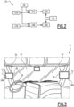
- the truck 10 comprises a camera monitoring system 20, shown in Figure 2 .
- This camera monitoring system 20 is preferably exclusively on board of the tractor 12.
- This camera monitoring system 20 comprises two cameras 22A, 22B, each able to capture an image of a respective scene, and, for each camera 22A, 22B, an image treatment system 24A, 24B and a display 26A, 26B.
- the camera monitoring system 20 further comprises a determination unit 28 for determining, for each camera 22A, 22B, an area of interest in the scene imaged by the camera 22A, 22B, and a configuration unit 30 for configuring each display 26A, 26B.
- a first one 22A of the cameras 22A, 22B is provided on the left side of the tractor 12, while the second camera 22B is provided on the right side of the tractor 12.
- Both cameras 22A, 22B are oriented toward the rear of the truck 10, which means that the scene imaged by each camera 22A, 22B is positioned rearward of the camera 22A, 22B.
- the field of view 32A, 32B of each camera 22A, 22B is centered on a direction extending rearward from the camera 22A, 22B.
- Each camera 22A, 22B is in particular oriented so that its field of view 32A, 32B includes a respective side 34A, 34B of the tractor 12.
- Each camera 22A, 22B consists in particular of a wide angle camera, which means that each camera 22A, 22B is able to capture a wide angle image of the scene imaged by the camera.
- the angular extent of the field of view 32A, 32B of the camera 22A, 22B is wide, i.e. is wider than 20 degrees.
- the horizontal angular extent of the field of view 32A, 32B of the camera 22A, 22B which is wide. It is not necessary for the vertical angular extent of the field of view of any of the cameras 22A, 22B to be wide. Preferably, the vertical angular extent of the field of view of both cameras 22A, 22B is comprised between 5 and 20 degrees.
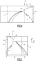
- the images provided by the cameras 22A, 22B are distorted, as can be seen on Figures 4 and 6 , where examples 50, 52 of images captured by the right camera 22B are provided.
- distorted it is meant that the magnification factor of these images changes across the field of view at a fixed working distance.
- the relation of a dimension of an object as it is shown in the image 50, 52 upon the angular size of the object as it is seen by the camera 22A, 22B changes depending on the location of the object in the image 50, 52.
- right lines such as the edges 54, 56 of the trailer 14, appear curved on the images 50, 52.
- Each camera 22A, 22B is configured for refreshing the image of its respective scene at a predetermined frequency, said frequency being preferably comprised between 40 and 80 frame per second, preferably between 50 and 70 frame per second.
- the displays 26A, 26B comprise a first display 26A associated with the first camera 22A and a second display 26B associated with the second camera 22B.
- Each display 26A, 26B is configured for displaying, in the field of view of the driver of the truck 10, a displayed image of the image captured by its associated camera 22A, 22B. Examples 60, 62 of such a display image, corresponding respectively to the wide angle images 50 and 52, are provided on Figures 5 and 6 .
- each display respectively 26A, 26B, comprises, with reference to Figure 3 , a display surface, respectively 36A, 36B, on which the displayed image is presented, said display surface 36A, 36B being positioned in the field of view of the driver of the truck 10.
- Each display 26A, 26B further comprises a display management unit (not shown) for displaying the displayed image on said surface 36A, 36B.
- the display surface 36A, 36B of each display 26A, 26B consists of a screen.
- the display surface 36A, 36B of each display 26A, 26B is provided on the same side of the cabin 16 as the associated camera 22A, 22B.
- the display surface 36A of the first display 26A is provided on left side of the cabin 16, while the display surface 36B of the second display 26B is provided on right side of the cabin 16.
- the display surface 36A, 36B which is the farthest from the steering wheel 38 is bigger than the other display surface 36A, 36B.
- the steering wheel 38 is provided on the left side of the cabin 16; the biggest display surface is therefore display surface 36B.
- Each display surface 36A, 36B is delimited by a frame 39 including an inner border 40 which is the closest to a longitudinal median plane M ( Figure 1 ) of the tractor 12, and an outer border 42 which is the farthest from said longitudinal median plane M.
- the inner and outer borders 40, 42 are thus spaced transversally from each other.
- the inner and outer borders 40, 42 are both oriented substantially vertically.
- the configuration unit 30 is configured for setting a first preset limit 44 and a second preset limit 45 to the wide angle image 50, 52, so that the displayed image 60, 62 only presents the part of the wide angle image 50, 52 comprised between said preset limits 44, 45.
- These preset limits 44, 45 are spaced apart from each other along a horizontal direction.
- the determination unit 28 is configured for determining, for each camera 22A, 22B, an area of interest in the scene imaged by the camera 22A, 22B.
- the determination unit 28 comprises typically a gaze tracking unit (not shown) for tracking a gaze direction of the driver and a main calculator (not shown) configured for determining, depending on the gaze direction, the position of an area of interest in the scene.
- the main calculator is configured to determine that an area of interest exists in the scene imaged by a camera 22A, 22B when the gaze direction is oriented toward the display surface 36A, 36B of the display 26A, 26B associated to said camera 22A, 22B.
- the main calculator is further configured to determine that the area of interest is in an angular sector of the field of view of the camera 22A, 22B which is increasingly far from the median plane M as the distance of the gaze direction from the inner border 40 increases.
- the main calculator provides a bijection between the distance of the gaze direction from the inner border 40 and the angle of view of the area of interest, defined as the angle between the longitudinal median plane M and the direction connecting the area of interest to the camera 22A, 22B, said bijection being an increasing function.
- the determination unit 28 comprises a head tracking unit (not shown) for tracking movement of a head of the driver and a main calculator (not shown) configured for determining, depending on the position of said head, the position of an area of interest in the scene.
- the main calculator is configured to determine that, the more the driver leans forward, the greater the angle of view of the area of interest is, said angle of view being defined as the angle between the longitudinal median plane M and the direction connecting the area of interest to the camera 22A, 22B; in other words, the main calculator provides a bijection between the distance of the distance of the head of the driver from the windshield 43 and the angle of view of the area of interest, said bijection being a decreasing function.
- the determination unit 28 comprises a trailer tracking unit (not shown) for tracking position of the trailer 14 relatively to the tractor 12 and a main calculator (not shown) configured for determining, depending on the position of said trailer 14, the position of an area of interest in the scene.
- the trailer tracking unit typically comprises a sensor for measuring an angle between the trailer 14 and the tractor 12.
- the trailer tracking unit comprises an image treatment system for identifying, in the images provided by the cameras 22A, 22B, the position of a rear end 46 ( Figure 1 ) of the trailer 14, and a secondary calculator configured to deduce thereof the position of the trailer 14 relatively to the tractor 12.
- the trailer tracking unit comprises sensors for measuring a steering angle of the tractor 12 and a speed of the tractor 12, and a secondary calculator configured to deduce thereof the position of the trailer 14 relatively to the tractor 12. In both latter cases, the secondary calculator may be merged with the main calculator.
- the main calculator is then configured for determining that the area of interest consists of the area of the scene in which the rear end 46 of the trailer 14 is.
- the determination unit 28 comprises at least two of the gaze tracking unit, head tracking unit and trailer tracking unit mentioned above.
- the main calculator is configured for deducing the position of the area of interest from the several pieces of information provided by the different tracking units.
- Each image treatment system 24A, 24B is configured for receiving the wide angle image captured by a respective one of the cameras 22A, 22B. Each image treatment system 24A, 24B is further configured for receiving from the determination unit 28 a signal indicating the location of an area of interest in the scene imaged by said respective camera 22A, 22B when the determination unit 28 has determined that such an area of interest is present in said scene.
- Each image treatment system 24A, 24B is configured to process the wide angle image captured by the respective camera 22A, 22B so as to provide the displayed image 60, 62, said displayed image 60, 62 comprising an undistorted portion 64 including the area of interest determined by the determination unit 28, and at least one distorted portion 66, 68.
- undistorted portion it is meant that the magnification factor provided by said portion 64 is constant throughout the portion 64. in other words, the relation of a dimension of an object as it is shown in the portion 64 upon the angular size of the object as it is seen by the camera 22A, 22B is the same for every object shown in the undistorted portion. As a consequence thereof, right lines, such as the edges 54, 56 of the trailer 14, are shown right in said undistorted portion 64.
- the image treatment system 24A, 24B is configured to provide the displayed image 60, 62 in such a manner that the undistorted portion 64 adjoins the at least one distorted portion 66, 68. For each distorted portion 66, 67, the undistorted portion 64 thus has an interface edge 68, 69 in contact with said distorted portion 66, 67.
- the image treatment system 24A, 24B is further configured to provide the displayed image 60, 62 in such a manner that the displayed image 60, 62 is continuous, i.e. so that there is not discontinuity in the image 60, 62, in particular at the interface between the undistorted portion 64 and the at least one distorted portion 66, 67.
- the image treatment system 24A, 24B is configured to provide the displayed image 60, 62 within a frame 70, said frame 70 having the same shape and the same ratio as the frame 39 of the display surface 36A, 36B of the corresponding display 26A, 26B.
- This frame 70 has an outer border 72, an inner border 74, an upper border 76 and a lower border 78, the upper and lower borders 76, 78 being spaced apart from each other along a first direction D1 while being substantially parallel to each other, the outer and inner border 72, 74 being spaced apart from each other along a second direction D2 while being substantially parallel to each other.
- the outer and inner borders 72, 74 are substantially parallel to the first direction D1
- the upper and lower borders 76, 78 are substantially parallel to the second direction D2.
- the first and second directions D1, D2 are advantageously, as shown, substantially orthogonal to each other.
- the image treatment system 24A, 24B is configured to provide the displayed image 60, 62 so that the inner border 74 consists of the first preset limit 44 of the wide angle image 50, 52, and the outer border 45 consists of the second preset limit 45 of the wide angle image 50, 5, whatever the position of the area of interest in the scene is.
- the image treatment system 24A, 24B is configured to provide the or each distorted portion 66, 67 interposed between the undistorted portion 64 and a respective one of the outer and inner borders 72, 74.
- the image treatment system 24A, 24B is further configured so that the or each interface edge 68, 69 of the undistorted portion 64 extends in the first direction D1.
- the image treatment system 24A, 24B is configured to provide the undistorted portion 64 with a first average magnification factor along the first direction D1 and with a second average magnification factor along the second direction D2, the second average magnification factor being substantially equal to the first average magnification factor.
- the first magnification factor is in particular comprised between 0.2 and 1.0.
- the image treatment system 24A, 24B is further configured to provide the or each distorted portion 66, 67 with a primary average magnification factor along the first direction D1 and with a secondary average magnification factor along the second direction D2.
- the primary average magnification factor is substantially equal to the first magnification factor, while the secondary average magnification factor is inferior to the second magnification factor.
- the image treatment system 24A, 24B is configured to provide the undistorted portion 64 with a fixed width along the second direction D2, independently of the position of the area of interest in the scene.
- Said width is preferably more than half the width of the displayed image 60, 62, measured from the outer border 72 to the inner border 74.
- the width of the undistorted portion 64 is approximately two thirds of the width of the displayed image 60, 62.
- the image treatment system 24A, 24B is configured to center the undistorted portion 64 on the area of interest and to displace the undistorted portion 64 in the displayed image 60, 62 depending on the position of the area of interest in the scene.
- the area of interest is closer from a preset limit 44, 45 than half the width of the undistorted portion 64, as shown in Figures 4 and 5 , then the undistorted portion 64 is in abutment against the inner or outer border 72, 74 of the displayed image 60, 62 and a single distorted portion 66 of the wide angle image 50 is provided between the undistorted portion 64 and the opposite border 72, 74.
- the undistorted portion 64 is spaced from both the inner and outer borders 72, 74 of the displayed image 60, 62 and distorted portions 66, 67 of the wide angle image 50 are provided on both sides of the undistorted portion 64 between said undistorted portion 64 and both inner and outer borders 72, 74.
- the corresponding display 26A, 26B is configured to display the displayed image 60, 62 as provided by the image treatment system 24A, 24B, the frame 70 of the displayed image 60, 62 matching the frame 39 of the display surface 36A, 36B, the inner border 74 matching the inner border 40 and the outer border 72 matching the outer border 42.
- the truck 10 is advancing straight ahead.
- the trailer 14 is then aligned with the tractor 12, and the image captured by the right camera 22B is then the image 50 shown in Figure 4 .
- the determination unit 28 determines that the area of interest is the angular sector in which the rear end 46 of the trailer 14 is located. This determination is made either by locating the trailer 14 relatively to the tractor 12, or by identifying an eye or head movement of the driver showing an interest of the driver in said angular sector.
- This information is provided by the determination unit 28 to the image treatment system 24B, which provides the displayed image 60 of Figure 5 . This image is then displayed by the display 26B on the display surface 36B.
- the truck 10 then turns right. As a consequence thereof, the trailer 14 is no longer aligned with the tractor 12 and is shifted toward the right side of the tractor 12.
- the image captured by the right camera 22B is then the image 52 shown in Figure 6 .
- the determination unit 28 determines that the area of interest is the angular sector in which the rear end 46 of the trailer 14 is located. This determination is made either by locating the trailer 14 relatively to the tractor 12, or by identifying an eye or head movement of the driver showing an interest of the driver in said angular sector.
- This information is provided by the determination unit 28 to the image treatment system 24B, which provides the displayed image 62 of Figure 7 , where the undistorted portion 64 has been displaced relatively to the image 60. This image is then displayed by the display 26B on the display surface 36B.
- the driver has a better view of the elements that are positioned on the right side of the rear end 46 of the trailer 14 and can thus more easily evaluate the distance of these objects from the rear end 46.
Landscapes
- Engineering & Computer Science (AREA)
- General Engineering & Computer Science (AREA)
- Theoretical Computer Science (AREA)
- Multimedia (AREA)
- Human Computer Interaction (AREA)
- Physics & Mathematics (AREA)
- General Physics & Mathematics (AREA)
- Mechanical Engineering (AREA)
- Closed-Circuit Television Systems (AREA)
Claims (12)
- Kameraüberwachungssystem (20) zum Bereitstellen einer Ansicht einer von einer Kamera aufgenommenen Szene für einen Benutzer, das Kameraüberwachungssystem (20) umfassend:- eine erste Weitwinkelkamera (22A) zum Aufnehmen eines ersten Weitwinkelbildes (50) einer Szene,- eine zweite Weitwinkelkamera (22B) zum Aufnehmen eines zweiten Weitwinkelbildes (52) einer Szene,- eine Bestimmungseinheit (28) zum Bestimmen eines Interessenbereichs in der Szene, wobei die Bestimmungseinheit (28) eine Blickverfolgungseinheit zum Verfolgen der Bewegung einer Blickrichtung des Benutzers umfasst,- ein Bildverarbeitungssystem (24A, 24B) zum Bereitstellen eines unverzerrten Teils (64), einschließlich des Interessenbereichs, sowohl des ersten Weitwinkelbildes (50) als auch des zweiten Weitwinkelbildes (52), und- eine Anzeige (26A, 26B) zum Anzeigen eines ersten kontinuierlichen angezeigten Bildes (60) des ersten Weitwinkelbildes (50) und eines zweiten kontinuierlichen angezeigten Bildes (62) des zweiten Weitwinkelbildes (52), wobei sowohl das erste angezeigte Bild (60) als auch das zweite angezeigte Bild (62) den unverzerrten Teil (64) umfassen, der an mindestens einen verzerrten Teil (66, 67) angrenzt und mit diesem zusammenhängt, und- wobei sowohl das erste Weitwinkelbild als auch das zweite Weitwinkelbild (50, 52) erste und zweite voreingestellte Grenzen (44, 45) aufweisen und sowohl das erste angezeigte Bild als auch das zweite angezeigte Bild (60, 62) erste und zweite gegenüberliegende Ränder (72, 74) aufweisen, wobei der oder jeder verzerrte Teil (66, 67) zwischen dem unverzerrten Teil (64) und einer der jeweiligen ersten und zweiten Ränder (72, 74) angeordnet ist, wobei die Anzeige (26A, 26B) konfiguriert ist, um die erste voreingestellte Grenze (44) an dem ersten Rand (74) und die zweite voreingestellte Grenze (45) an dem zweiten Rand (72) unabhängig von der Position des Interessenbereichs anzuzeigen.
- Kameraüberwachungssystem (20) nach Anspruch 1, wobei der unverzerrte Teil (64) einen ersten durchschnittlichen Vergrößerungsfaktor entlang einer ersten Richtung (D1) des angezeigten Bildes (60, 62) und einen zweiten durchschnittlichen Vergrößerungsfaktor entlang einer zweiten Richtung (D2), orthogonal zur ersten Richtung (D1), des angezeigten Bildes (60, 62) aufweist, wobei der erste und der zweite durchschnittliche Vergrößerungsfaktor im Wesentlichen gleich sind.
- Kameraüberwachungssystem (20) nach Anspruch 2, wobei der erste und der zweite Rand (72, 74) entlang der zweiten Richtung (D2) voneinander beabstandet sind und vorzugsweise im Wesentlichen parallel zu der ersten Richtung (D1) verlaufen.
- Kameraüberwachungssystem (20) nach Anspruch 2 oder 3, wobei der oder jeder verzerrte Teil (66, 67) einen primären durchschnittlichen Vergrößerungsfaktor entlang der ersten Richtung (D1) und einen sekundären durchschnittlichen Vergrößerungsfaktor entlang der zweiten Richtung (D2) aufweist, wobei der primäre durchschnittliche Vergrößerungsfaktor im Wesentlichen gleich dem ersten durchschnittlichen Vergrößerungsfaktor ist und der sekundäre durchschnittliche Vergrößerungsfaktor kleiner als der zweite durchschnittliche Vergrößerungsfaktor ist.
- Kameraüberwachungssystem (20) nach einem der Ansprüche 2 bis 4, wobei für den oder jeden angezeigten verzerrten Teil (66, 67) der unverzerrte Teil (64) eine Schnittstellenkante (68, 69) in Kontakt mit dem verzerrten Teil (66, 67) aufweist, wobei sich die Schnittstellenkante (68, 69) entlang der ersten Richtung (D1) erstreckt.
- Kameraüberwachungssystem (20) nach einem der Ansprüche 2 bis 5, wobei der erste durchschnittliche Vergrößerungsfaktor zwischen 0,2 und 1,0 liegt.
- Kameraüberwachungssystem (20) nach einem der vorhergehenden Ansprüche, wobei die Bestimmungseinheit (28) eine Head-Trackingeinheit zur Verfolgung der Bewegung eines Kopfes des Benutzers umfasst.
- Kameraüberwachungssystem (20) nach einem der vorhergehenden Ansprüche, wobei die Anzeige (26A, 26B) konfiguriert ist, um den unverzerrten Teil (64) im angezeigten Bild (60, 62) in Abhängigkeit von der Position des Interessenbereichs in der Szene zu verlagern.
- Kameraüberwachungssystem (20) nach einem der vorhergehenden Ansprüche, wobei sowohl die erste Weitwinkelkamera (22A) als auch die zweite Weitwinkelkamera (22B) konfiguriert sind, um das erste Weitwinkelbild (50) bzw. das zweite Weitwinkelbild (52) mit einer vorbestimmten Frequenz aufzufrischen.
- Kraftfahrzeug (10) umfassend das Kameraüberwachungssystem (20) nach einem der vorhergehenden Ansprüche, wobei sowohl die erste Weitwinkelkamera (22A) als auch die zweite Weitwinkelkamera (22B) jeweils zum Heck des Fahrzeugs (10) hin ausgerichtet sind, wobei die Anzeige (26A, 26B) eine Anzeigefläche (36A, 36B) aufweist, auf der das angezeigte Bild (50, 52) dargestellt wird, wobei die Anzeigefläche (36A, 36B) im Sichtfeld eines Fahrers des Fahrzeugs (10) positioniert ist.
- Kraftfahrzeug (10) nach Anspruch 10, umfassend eine Zugmaschine (12) und einen Anhänger (14), wobei die Bestimmungseinheit (28) eine Anhängerverfolgungseinheit zum Verfolgen der Position des Anhängers (14) relativ zur Zugmaschine (12) umfasst.
- Verfahren zum Bereitstellen einer Ansicht einer von einer Kamera aufgenommenen Szene für einen Benutzer, das Verfahren umfassend:- Aufnehmen eines ersten Weitwinkelbildes (50) einer Szene mit einer ersten Weitwinkelkamera (22A) und eines zweiten Weitwinkelbildes (52) der Szene mit einer zweiten Weitwinkelkamera (22B),- Bestimmen eines Interessenbereichs in der Szene,- Verfolgen der Bewegung einer Blickrichtung des Benutzers,- Bereitstellen eines unverzerrten Teils (64), einschließlich des Interessenbereichs, sowohl des ersten Weitwinkelbildes (50) als auch des zweiten Weitwinkelbildes (52), und- Anzeigen, für sowohl das erste Weitwinkelbild (50) als auch das zweite Weitwinkelbild (52), eines kontinuierlichen angezeigten Bildes (60, 62) des ersten Weitwinkelbildes (50) und des zweiten Weitwinkelbildes (52), wobei das angezeigte Bild (60, 62) den unverzerrten Teil (64) umfasst, der an mindestens einen verzerrten Teil (66, 67) angrenzt und mit diesem zusammenhängt, wobei sowohl das erste Weitwinkelbild als auch das zweite Weitwinkelbild (50, 52) erste und zweite voreingestellte Grenzen (44, 45) aufweisen und sowohl das erste angezeigte Bild als auch das zweite angezeigte Bild (60, 62) erste und zweite gegenüberliegende Ränder (72, 74) aufweisen, wobei der oder jeder verzerrte Teil (66, 67) zwischen dem unverzerrten Teil (64) und einer der jeweiligen ersten und zweiten Ränder (72, 74) angeordnet ist, wobei die erste voreingestellte Grenze (44) an dem ersten Rand (74) und die zweite voreingestellte Grenze (45) an dem zweiten Rand (72) unabhängig von der Position des Interessenbereichs angezeigt wird.
Applications Claiming Priority (1)
| Application Number | Priority Date | Filing Date | Title |
|---|---|---|---|
| PCT/IB2018/000137 WO2019135099A1 (en) | 2018-01-05 | 2018-01-05 | Camera monitoring system with a display displaying an undistorted portion of a wide angle image adjoining at least one distorted portion of the wide angle image |
Publications (3)
| Publication Number | Publication Date |
|---|---|
| EP3735673A1 EP3735673A1 (de) | 2020-11-11 |
| EP3735673B1 true EP3735673B1 (de) | 2024-09-11 |
| EP3735673C0 EP3735673C0 (de) | 2024-09-11 |
Family
ID=61627130
Family Applications (1)
| Application Number | Title | Priority Date | Filing Date |
|---|---|---|---|
| EP18710911.1A Active EP3735673B1 (de) | 2018-01-05 | 2018-01-05 | Kameraüberwachungssystem mit einer anzeige, die einen unverzerrten teil eines weitwinkelbildes anzeigt, der an mindestens einen verzerrten teil des weitwinkelbildes angrenzt |
Country Status (4)
| Country | Link |
|---|---|
| US (1) | US11613207B2 (de) |
| EP (1) | EP3735673B1 (de) |
| CN (1) | CN111480175A (de) |
| WO (1) | WO2019135099A1 (de) |
Families Citing this family (2)
| Publication number | Priority date | Publication date | Assignee | Title |
|---|---|---|---|---|
| US11220214B1 (en) * | 2020-08-04 | 2022-01-11 | Robert Bosch Gmbh | Vehicle viewing system and method including electronic image displays for rearward viewing by a driver |
| GB2609615A (en) * | 2021-08-03 | 2023-02-15 | Continental Automotive Gmbh | Vehicle surround view system and method thereof |
Citations (3)
| Publication number | Priority date | Publication date | Assignee | Title |
|---|---|---|---|---|
| DE102010005812A1 (de) * | 2010-01-27 | 2011-07-28 | Bayerische Motoren Werke Aktiengesellschaft, 80809 | Instrumententafel eines Kraftfahrzeuges mit einem Ablagefach |
| WO2014204794A1 (en) * | 2013-06-21 | 2014-12-24 | Magna Electronics Inc. | Vehicle vision system |
| EP3029929A1 (de) * | 2014-12-05 | 2016-06-08 | MEKRA LANG GmbH & Co. KG | Sichtsystem |
Family Cites Families (11)
| Publication number | Priority date | Publication date | Assignee | Title |
|---|---|---|---|---|
| JP4195966B2 (ja) | 2002-03-05 | 2008-12-17 | パナソニック株式会社 | 画像表示制御装置 |
| WO2011030698A1 (ja) * | 2009-09-11 | 2011-03-17 | アイシン精機株式会社 | 車両周辺監視装置 |
| JP2011203446A (ja) * | 2010-03-25 | 2011-10-13 | Fujifilm Corp | ヘッドマウントディスプレイ装置 |
| US8994825B2 (en) * | 2011-07-28 | 2015-03-31 | Robert Bosch Gmbh | Vehicle rear view camera system and method |
| US9998659B2 (en) * | 2012-03-01 | 2018-06-12 | Geo Semiconductor Inc. | Method and system for adaptive perspective correction of ultra wide-angle lens images |
| US20130278715A1 (en) * | 2012-03-16 | 2013-10-24 | Mark Nutsch | System and method for discreetly collecting 3d immersive/panoramic imagery |
| CN103310411B (zh) * | 2012-09-25 | 2017-04-12 | 中兴通讯股份有限公司 | 一种图像局部增强方法和装置 |
| GB201301445D0 (en) * | 2013-01-28 | 2013-03-13 | Microsoft Corp | Adapting robustness in video coding |
| JP6036601B2 (ja) * | 2013-08-09 | 2016-11-30 | 株式会社デンソー | 画像処理装置及び画像処理方法 |
| JP6384188B2 (ja) * | 2014-08-12 | 2018-09-05 | ソニー株式会社 | 車両用表示装置と表示制御方法および後方モニタリングシステム |
| EP3176035A1 (de) * | 2015-12-03 | 2017-06-07 | Fico Mirrors S.A. | Rückspiegelsystem für ein kraftfahrzeug |
-
2018
- 2018-01-05 EP EP18710911.1A patent/EP3735673B1/de active Active
- 2018-01-05 CN CN201880081172.2A patent/CN111480175A/zh active Pending
- 2018-01-05 US US16/771,082 patent/US11613207B2/en active Active
- 2018-01-05 WO PCT/IB2018/000137 patent/WO2019135099A1/en not_active Ceased
Patent Citations (3)
| Publication number | Priority date | Publication date | Assignee | Title |
|---|---|---|---|---|
| DE102010005812A1 (de) * | 2010-01-27 | 2011-07-28 | Bayerische Motoren Werke Aktiengesellschaft, 80809 | Instrumententafel eines Kraftfahrzeuges mit einem Ablagefach |
| WO2014204794A1 (en) * | 2013-06-21 | 2014-12-24 | Magna Electronics Inc. | Vehicle vision system |
| EP3029929A1 (de) * | 2014-12-05 | 2016-06-08 | MEKRA LANG GmbH & Co. KG | Sichtsystem |
Also Published As
| Publication number | Publication date |
|---|---|
| CN111480175A (zh) | 2020-07-31 |
| WO2019135099A1 (en) | 2019-07-11 |
| EP3735673C0 (de) | 2024-09-11 |
| US11613207B2 (en) | 2023-03-28 |
| EP3735673A1 (de) | 2020-11-11 |
| US20210178967A1 (en) | 2021-06-17 |
Similar Documents
| Publication | Publication Date | Title |
|---|---|---|
| US11553153B2 (en) | Display system and method | |
| US10960822B2 (en) | Vehicular rearview vision system with A-pillar display | |
| USRE48017E1 (en) | Viewing system for vehicles, in particular commercial vehicles | |
| US9457632B1 (en) | Collision avoidance method including determining height of an object fixed to a vehicle | |
| JP7171743B2 (ja) | 自動車のためのカメラモニタシステム、および自動車のためのカメラモニタシステムを動作させるための方法および装置 | |
| US10000155B2 (en) | Method and device for reproducing a lateral and/or rear surrounding area of a vehicle | |
| US20130096820A1 (en) | Virtual display system for a vehicle | |
| JP6035298B2 (ja) | ビジュアルシステム | |
| JP2019064580A (ja) | 車両インストルメントコンソール上に3次元画像を表示するシステム及び方法 | |
| US7423521B2 (en) | Vehicular visual assistance system | |
| WO2017037267A1 (en) | Display system and method | |
| US10618469B2 (en) | Systems and methods for the representation of a rear outer region of a vehicle | |
| CN118414635A (zh) | 包括车轮位置估算的商用车辆的摄像头监控系统 | |
| US9630568B2 (en) | Camera system for a motor vehicle | |
| GB2529408A (en) | Display system and method | |
| EP3735673B1 (de) | Kameraüberwachungssystem mit einer anzeige, die einen unverzerrten teil eines weitwinkelbildes anzeigt, der an mindestens einen verzerrten teil des weitwinkelbildes angrenzt | |
| US20220072999A1 (en) | Method and apparatus for side mirror auto adjust for trailering in a motor vehicle | |
| US10933812B1 (en) | Outside-vehicle environment monitoring apparatus | |
| EP4361999B1 (de) | Kameramonitorsystem mit abgewinkelten bewusstseinslinien |
Legal Events
| Date | Code | Title | Description |
|---|---|---|---|
| STAA | Information on the status of an ep patent application or granted ep patent |
Free format text: STATUS: UNKNOWN |
|
| STAA | Information on the status of an ep patent application or granted ep patent |
Free format text: STATUS: THE INTERNATIONAL PUBLICATION HAS BEEN MADE |
|
| PUAI | Public reference made under article 153(3) epc to a published international application that has entered the european phase |
Free format text: ORIGINAL CODE: 0009012 |
|
| STAA | Information on the status of an ep patent application or granted ep patent |
Free format text: STATUS: REQUEST FOR EXAMINATION WAS MADE |
|
| 17P | Request for examination filed |
Effective date: 20200619 |
|
| AK | Designated contracting states |
Kind code of ref document: A1 Designated state(s): AL AT BE BG CH CY CZ DE DK EE ES FI FR GB GR HR HU IE IS IT LI LT LU LV MC MK MT NL NO PL PT RO RS SE SI SK SM TR |
|
| AX | Request for extension of the european patent |
Extension state: BA ME |
|
| DAV | Request for validation of the european patent (deleted) | ||
| DAX | Request for extension of the european patent (deleted) | ||
| STAA | Information on the status of an ep patent application or granted ep patent |
Free format text: STATUS: EXAMINATION IS IN PROGRESS |
|
| 17Q | First examination report despatched |
Effective date: 20210519 |
|
| GRAP | Despatch of communication of intention to grant a patent |
Free format text: ORIGINAL CODE: EPIDOSNIGR1 |
|
| STAA | Information on the status of an ep patent application or granted ep patent |
Free format text: STATUS: GRANT OF PATENT IS INTENDED |
|
| INTG | Intention to grant announced |
Effective date: 20240418 |
|
| GRAS | Grant fee paid |
Free format text: ORIGINAL CODE: EPIDOSNIGR3 |
|
| GRAA | (expected) grant |
Free format text: ORIGINAL CODE: 0009210 |
|
| STAA | Information on the status of an ep patent application or granted ep patent |
Free format text: STATUS: THE PATENT HAS BEEN GRANTED |
|
| AK | Designated contracting states |
Kind code of ref document: B1 Designated state(s): AL AT BE BG CH CY CZ DE DK EE ES FI FR GB GR HR HU IE IS IT LI LT LU LV MC MK MT NL NO PL PT RO RS SE SI SK SM TR |
|
| REG | Reference to a national code |
Ref country code: GB Ref legal event code: FG4D |
|
| REG | Reference to a national code |
Ref country code: CH Ref legal event code: EP |
|
| REG | Reference to a national code |
Ref country code: DE Ref legal event code: R096 Ref document number: 602018074211 Country of ref document: DE |
|
| REG | Reference to a national code |
Ref country code: IE Ref legal event code: FG4D |
|
| U01 | Request for unitary effect filed |
Effective date: 20241010 |
|
| U07 | Unitary effect registered |
Designated state(s): AT BE BG DE DK EE FI FR IT LT LU LV MT NL PT RO SE SI Effective date: 20241029 |
|
| PG25 | Lapsed in a contracting state [announced via postgrant information from national office to epo] |
Ref country code: NO Free format text: LAPSE BECAUSE OF FAILURE TO SUBMIT A TRANSLATION OF THE DESCRIPTION OR TO PAY THE FEE WITHIN THE PRESCRIBED TIME-LIMIT Effective date: 20241211 |
|
| PG25 | Lapsed in a contracting state [announced via postgrant information from national office to epo] |
Ref country code: GR Free format text: LAPSE BECAUSE OF FAILURE TO SUBMIT A TRANSLATION OF THE DESCRIPTION OR TO PAY THE FEE WITHIN THE PRESCRIBED TIME-LIMIT Effective date: 20241212 |
|
| PG25 | Lapsed in a contracting state [announced via postgrant information from national office to epo] |
Ref country code: HR Free format text: LAPSE BECAUSE OF FAILURE TO SUBMIT A TRANSLATION OF THE DESCRIPTION OR TO PAY THE FEE WITHIN THE PRESCRIBED TIME-LIMIT Effective date: 20240911 |
|
| PG25 | Lapsed in a contracting state [announced via postgrant information from national office to epo] |
Ref country code: RS Free format text: LAPSE BECAUSE OF FAILURE TO SUBMIT A TRANSLATION OF THE DESCRIPTION OR TO PAY THE FEE WITHIN THE PRESCRIBED TIME-LIMIT Effective date: 20241211 Ref country code: ES Free format text: LAPSE BECAUSE OF FAILURE TO SUBMIT A TRANSLATION OF THE DESCRIPTION OR TO PAY THE FEE WITHIN THE PRESCRIBED TIME-LIMIT Effective date: 20240911 |
|
| PG25 | Lapsed in a contracting state [announced via postgrant information from national office to epo] |
Ref country code: RS Free format text: LAPSE BECAUSE OF FAILURE TO SUBMIT A TRANSLATION OF THE DESCRIPTION OR TO PAY THE FEE WITHIN THE PRESCRIBED TIME-LIMIT Effective date: 20241211 Ref country code: NO Free format text: LAPSE BECAUSE OF FAILURE TO SUBMIT A TRANSLATION OF THE DESCRIPTION OR TO PAY THE FEE WITHIN THE PRESCRIBED TIME-LIMIT Effective date: 20241211 Ref country code: HR Free format text: LAPSE BECAUSE OF FAILURE TO SUBMIT A TRANSLATION OF THE DESCRIPTION OR TO PAY THE FEE WITHIN THE PRESCRIBED TIME-LIMIT Effective date: 20240911 Ref country code: GR Free format text: LAPSE BECAUSE OF FAILURE TO SUBMIT A TRANSLATION OF THE DESCRIPTION OR TO PAY THE FEE WITHIN THE PRESCRIBED TIME-LIMIT Effective date: 20241212 Ref country code: ES Free format text: LAPSE BECAUSE OF FAILURE TO SUBMIT A TRANSLATION OF THE DESCRIPTION OR TO PAY THE FEE WITHIN THE PRESCRIBED TIME-LIMIT Effective date: 20240911 |
|
| U20 | Renewal fee for the european patent with unitary effect paid |
Year of fee payment: 8 Effective date: 20250127 |
|
| PG25 | Lapsed in a contracting state [announced via postgrant information from national office to epo] |
Ref country code: IS Free format text: LAPSE BECAUSE OF FAILURE TO SUBMIT A TRANSLATION OF THE DESCRIPTION OR TO PAY THE FEE WITHIN THE PRESCRIBED TIME-LIMIT Effective date: 20250111 |
|
| PG25 | Lapsed in a contracting state [announced via postgrant information from national office to epo] |
Ref country code: SM Free format text: LAPSE BECAUSE OF FAILURE TO SUBMIT A TRANSLATION OF THE DESCRIPTION OR TO PAY THE FEE WITHIN THE PRESCRIBED TIME-LIMIT Effective date: 20240911 |
|
| PG25 | Lapsed in a contracting state [announced via postgrant information from national office to epo] |
Ref country code: CZ Free format text: LAPSE BECAUSE OF FAILURE TO SUBMIT A TRANSLATION OF THE DESCRIPTION OR TO PAY THE FEE WITHIN THE PRESCRIBED TIME-LIMIT Effective date: 20240911 Ref country code: PL Free format text: LAPSE BECAUSE OF FAILURE TO SUBMIT A TRANSLATION OF THE DESCRIPTION OR TO PAY THE FEE WITHIN THE PRESCRIBED TIME-LIMIT Effective date: 20240911 |
|
| PG25 | Lapsed in a contracting state [announced via postgrant information from national office to epo] |
Ref country code: SK Free format text: LAPSE BECAUSE OF FAILURE TO SUBMIT A TRANSLATION OF THE DESCRIPTION OR TO PAY THE FEE WITHIN THE PRESCRIBED TIME-LIMIT Effective date: 20240911 |
|
| PLBE | No opposition filed within time limit |
Free format text: ORIGINAL CODE: 0009261 |
|
| STAA | Information on the status of an ep patent application or granted ep patent |
Free format text: STATUS: NO OPPOSITION FILED WITHIN TIME LIMIT |
|
| 26N | No opposition filed |
Effective date: 20250612 |
|
| REG | Reference to a national code |
Ref country code: CH Ref legal event code: PL |
|
| PG25 | Lapsed in a contracting state [announced via postgrant information from national office to epo] |
Ref country code: MC Free format text: LAPSE BECAUSE OF FAILURE TO SUBMIT A TRANSLATION OF THE DESCRIPTION OR TO PAY THE FEE WITHIN THE PRESCRIBED TIME-LIMIT Effective date: 20240911 |
|
| GBPC | Gb: european patent ceased through non-payment of renewal fee |
Effective date: 20250105 |
|
| PG25 | Lapsed in a contracting state [announced via postgrant information from national office to epo] |
Ref country code: GB Free format text: LAPSE BECAUSE OF NON-PAYMENT OF DUE FEES Effective date: 20250105 |
|
| PG25 | Lapsed in a contracting state [announced via postgrant information from national office to epo] |
Ref country code: CH Free format text: LAPSE BECAUSE OF NON-PAYMENT OF DUE FEES Effective date: 20250131 |
|
| PG25 | Lapsed in a contracting state [announced via postgrant information from national office to epo] |
Ref country code: IE Free format text: LAPSE BECAUSE OF NON-PAYMENT OF DUE FEES Effective date: 20250105 |
|
| U20 | Renewal fee for the european patent with unitary effect paid |
Year of fee payment: 9 Effective date: 20260126 |