EP3735530B1 - Rotorblatt für eine windenergieanlage und verfahren - Google Patents
Rotorblatt für eine windenergieanlage und verfahren Download PDFInfo
- Publication number
- EP3735530B1 EP3735530B1 EP19705314.3A EP19705314A EP3735530B1 EP 3735530 B1 EP3735530 B1 EP 3735530B1 EP 19705314 A EP19705314 A EP 19705314A EP 3735530 B1 EP3735530 B1 EP 3735530B1
- Authority
- EP
- European Patent Office
- Prior art keywords
- blade
- rotor blade
- value range
- rotor
- separating point
- Prior art date
- Legal status (The legal status is an assumption and is not a legal conclusion. Google has not performed a legal analysis and makes no representation as to the accuracy of the status listed.)
- Active
Links
Images


Classifications
-
- F—MECHANICAL ENGINEERING; LIGHTING; HEATING; WEAPONS; BLASTING
- F03—MACHINES OR ENGINES FOR LIQUIDS; WIND, SPRING, OR WEIGHT MOTORS; PRODUCING MECHANICAL POWER OR A REACTIVE PROPULSIVE THRUST, NOT OTHERWISE PROVIDED FOR
- F03D—WIND MOTORS
- F03D1/00—Wind motors with rotation axis substantially parallel to the air flow entering the rotor
- F03D1/06—Rotors
- F03D1/0608—Rotors characterised by their aerodynamic shape
- F03D1/0633—Rotors characterised by their aerodynamic shape of the blades
-
- F—MECHANICAL ENGINEERING; LIGHTING; HEATING; WEAPONS; BLASTING
- F03—MACHINES OR ENGINES FOR LIQUIDS; WIND, SPRING, OR WEIGHT MOTORS; PRODUCING MECHANICAL POWER OR A REACTIVE PROPULSIVE THRUST, NOT OTHERWISE PROVIDED FOR
- F03D—WIND MOTORS
- F03D1/00—Wind motors with rotation axis substantially parallel to the air flow entering the rotor
- F03D1/06—Rotors
- F03D1/065—Rotors characterised by their construction elements
- F03D1/0658—Arrangements for fixing wind-engaging parts to a hub
-
- F—MECHANICAL ENGINEERING; LIGHTING; HEATING; WEAPONS; BLASTING
- F03—MACHINES OR ENGINES FOR LIQUIDS; WIND, SPRING, OR WEIGHT MOTORS; PRODUCING MECHANICAL POWER OR A REACTIVE PROPULSIVE THRUST, NOT OTHERWISE PROVIDED FOR
- F03D—WIND MOTORS
- F03D1/00—Wind motors with rotation axis substantially parallel to the air flow entering the rotor
- F03D1/06—Rotors
- F03D1/065—Rotors characterised by their construction elements
- F03D1/0675—Rotors characterised by their construction elements of the blades
-
- F—MECHANICAL ENGINEERING; LIGHTING; HEATING; WEAPONS; BLASTING
- F05—INDEXING SCHEMES RELATING TO ENGINES OR PUMPS IN VARIOUS SUBCLASSES OF CLASSES F01-F04
- F05B—INDEXING SCHEME RELATING TO WIND, SPRING, WEIGHT, INERTIA OR LIKE MOTORS, TO MACHINES OR ENGINES FOR LIQUIDS COVERED BY SUBCLASSES F03B, F03D AND F03G
- F05B2240/00—Components
- F05B2240/20—Rotors
- F05B2240/30—Characteristics of rotor blades, i.e. of any element transforming dynamic fluid energy to or from rotational energy and being attached to a rotor
- F05B2240/302—Segmented or sectional blades
-
- Y—GENERAL TAGGING OF NEW TECHNOLOGICAL DEVELOPMENTS; GENERAL TAGGING OF CROSS-SECTIONAL TECHNOLOGIES SPANNING OVER SEVERAL SECTIONS OF THE IPC; TECHNICAL SUBJECTS COVERED BY FORMER USPC CROSS-REFERENCE ART COLLECTIONS [XRACs] AND DIGESTS
- Y02—TECHNOLOGIES OR APPLICATIONS FOR MITIGATION OR ADAPTATION AGAINST CLIMATE CHANGE
- Y02E—REDUCTION OF GREENHOUSE GAS [GHG] EMISSIONS, RELATED TO ENERGY GENERATION, TRANSMISSION OR DISTRIBUTION
- Y02E10/00—Energy generation through renewable energy sources
- Y02E10/70—Wind energy
- Y02E10/72—Wind turbines with rotation axis in wind direction
Definitions
- the present invention relates to a rotor blade for a wind energy installation, a wind energy installation, a wind park and a method for designing a two-part rotor blade.
- Wind energy plants of the type mentioned at the beginning are known.
- the currently most common type of wind energy installation is the so-called horizontal axis wind energy installation, which is usually equipped with three rotor blades, whereby wind energy installations with one, two, four or more rotor blades are also possible.
- Such wind turbines have increasingly larger designs in order, on the one hand, to be able to achieve a higher nominal power and, on the other hand, to enable better utilization of wind, the ultimate goal being to increase the economic efficiency of wind turbines.
- split rotor blades are generally transported from a production site to a site for setting up the wind energy installation and mounted there on the hub, the use of split rotor blades is often necessary or advantageous, particularly in the case of rotor blades with large longitudinal extensions.
- Split rotor blades are easier to transport than undivided rotor blades.
- Split rotor blades which therefore have two or more adjacent sections in the longitudinal direction, are, for example, from FIG DE 10 2014 206 670 A1 known. Especially at installation locations in forest areas or mountainous areas Regions may require split rotor blades so that transport to the installation site is even possible.
- Another example of the prior art is from WO2010 / 086297 known, which also shows split rotor blades.
- a disadvantage of conventional, two-part rotor blades is that they have no or only a limited aerodynamically optimal profile due to the separation point. Because of this, the efficiency or the yield of the wind energy installation is reduced and furthermore force and / or torque curves are negatively influenced.
- German Patent and Trademark Office researched the following prior art in the priority application for the present application: DE 10 2012 206 109 B3 ; DE 10 2015 116 634 A1 and DE 10 2016 201 114 A1 .
- the aforementioned object is achieved by a rotor blade for a wind turbine that extends in the longitudinal direction from a blade connection to a blade tip with a variable profile depth, the rotor blade being divided at a separation point and a separation point at the separation point Profile depth, a relative blade length of the rotor blade based on the blade connection is defined in a blade length value range between 0% to 100%, the separation point is arranged in a blade length value range between 25% and 50%, a rotor blade section facing the blade connection and a rotor blade section facing away from the blade connection can be connected for proper operation of the rotor blade at the separation point, a depth ratio is defined from the variable profile depth and the separation point profile depth, a development index as a gradient of the depth ratio in the direction of the relative blade length e is defined, and the development index in the area of the separation point is less than -1.
- the rotor blade preferably has an idealized two-dimensional extension which is formed by a longitudinal extension in the longitudinal direction and by the profile depth running essentially orthogonally thereto.
- the profile depth describes in particular the Extension of the rotor blade from a leading edge to a trailing edge of the rotor blade.
- the profile depth is therefore designed to be variable, since the extension of the rotor blade in the direction of the profile depth is essentially not constant. Nevertheless, the rotor blade can also have sections in which the profile depth is essentially constant.
- the rotor blade has a rotor blade thickness orthogonally to the longitudinal extent and orthogonally to the profile depth.
- the rotor blade is divided into two sections along the longitudinal direction, which meet at the separation point.
- the separation point can extend completely or in sections essentially orthogonally to the longitudinal direction of the rotor blade.
- the separation point preferably has a dividing plane which corresponds to an abutment surface of one or both rotor blade sections or rotor blade sections.
- the separation point can be arranged such that the longitudinal direction of the rotor blade is aligned parallel to a surface orthogonal of the parting plane of the separation point. In this case, the parting plane essentially has extensions in the direction of the profile depth and the rotor blade thickness.
- the parting plane of the separation point is aligned completely or in sections at an incline to the longitudinal direction of the rotor blade.
- An inclined parting plane of the separation point means in particular that the parting plane extends on the one hand in the direction of the rotor blade thickness, but also in the longitudinal direction of the rotor blade and in the direction of the profile depth.
- the separation point can also have other geometries, for example it can extend in a zigzag shape.
- variable profile depth takes on a value at the separation point, namely the separation point profile depth. If the course of the separation point does not allow a specific value for determining the profile depth or allows several values for the separation point profile depth, it is preferred to form an average value from the possible separation point profile depths. This can be the case, for example, with inclined dividing planes or zigzag-shaped separating points. In addition, a minimum separation point profile depth or a maximum separation point profile depth can also be used.
- the relative leaf length always has a leaf length value between 0% and 100%.
- a blade length value of 0% is preferably assigned to the blade connection.
- a blade length value of 100% is also preferably assigned to the blade tip.
- the separation point is arranged in a sheet length value range between 25% and 50%.
- the separation point is spaced between 10 meters and 20 meters from the blade connection.
- the rotor blade has essentially two rotor blade sections, namely the rotor blade section facing the blade connection and the rotor blade section facing away from the blade connection.
- the rotor blade section facing the blade connection is the rotor blade section which on the one hand adjoins the separation point and also has the blade connection or faces it.
- the rotor blade section facing the blade connection also faces a hub of a wind energy installation and thus comprises the proximal end of the rotor blade.
- the rotor blade section facing away from the blade connection is that rotor blade section which on the one hand adjoins the separation point and furthermore has the blade tip or adjoins this blade tip.
- the rotor blade section facing away from the blade connection thus comprises the distal end of the rotor blade.
- the depth ratio results from the variable profile depth and the separation point profile depth.
- the depth ratio is thus determined from the variable profile depth and the constant separation point profile depth.
- the depth ratio is therefore generally always equal to 1.
- the depth ratio in the blade length range from 0% to the separation point has a value greater than 1.
- the depth ratio In the area from the separation point to a blade length value of 100%, the depth ratio generally has a value of less than 1.
- the development index is determined as a gradient of the depth ratio in the direction of the relative leaf length.
- the development index is thus calculated in particular by deriving the depth ratio from the relative leaf length.
- the development index is less than -1. This means that the depth ratio in the area of the separation point decreases comparatively strongly.
- the invention is based, inter alia, on the knowledge that, in the case of divided rotor blades, the system loads are reduced by rapidly decreasing the profile depth from the separation point to the blade tip. For the assembly, however, a minimum absolute blade thickness must be observed at the separation point, which influences the aerodynamic design of the rotor blade. In order to be able to use the logistical advantage of the split rotor blade effectively without having to do this again with the disadvantage of greatly increased system loads reduce, a development index in the area of the separation point of less than -1 is proposed.
- the area of the separation point can extend, among other things, in the longitudinal direction of the rotor blade.
- the area of the separation point preferably extends in the longitudinal direction of the rotor blade from a lower area limit, which faces the blade connection, to an upper area limit, which faces away from the blade connection.
- the lower range limit is preferably spaced apart from the separation point in the direction of the blade connection with an extension which is less than 0.1%, 0.5%, 1%, 2%, 5% and / or 7% of the relative blade length.
- the upper limit of the range is preferably spaced from the separation point in the direction of the blade tip with an extension which is less than 0.1%, 0.5%, 1%, 2%, 5% and / or 7% of the relative blade length.
- the separation point is arranged in a blade length value range between 32% and 40%.
- the invention is also based on the knowledge that it is advantageous to reduce the profile depth in the rotor blade section facing away from the blade connection as quickly as possible in order to be able to implement structural improvements on the rotor blade.
- the disadvantage of an increased rotor blade mass of divided rotor blades can be compensated for.
- the efficiency of the rotor blade is improved, so that the yield can be increased.
- the invention is based on the knowledge that a reduction in the relative rotor blade thickness, that is to say a ratio of rotor blade thickness to profile depth, results in aerodynamic advantages.
- the relative rotor blade thickness at the separation point is preferably in the range of 0.4 to 0.5.
- a construction dimension is preferably defined as a certain integral of the relative rotor blade thickness over a range of the relative blade length, a lower limit of the integral being set at a position of 20% of the relative blade length and the construction dimension being evaluable for any values of the upper limit, the construction dimension for an upper limit of 45% of the relative sheet length is at least 0.1 and / or the design dimension for an upper limit of 80% of the relative sheet length is at least 0.2.
- the development index thus has a local minimum in the area of the separation point.
- the development index in the region of the separation point is in a dimension value range between -3 and -1, particularly preferably in a dimension value range between -2.5 and -2.
- the development index in the blade length value range between 50% and 90%, in particular between 55% and 80% can have an increasing value.
- the development index in the blade length value range between 25% and 50%, in particular between 32% and 40%, is less than -1.
- the development index in the sheet length value range between 25% and 50%, in particular between 32% and 40%, less than -1.5, and / or -2, and / or -2.2, and / or -2.4.
- Another preferred development of the rotor blade is characterized in that in the blade length value range between 60% and 80% the development index lies in the dimension index value range between -1.1 and -0.5. It is further preferred that the development index decreases from the relative sheet length of 25% to the separation point and / or the development index increases from the separation point towards the relative sheet length of 90%.
- a rotor blade with a development index according to one or more of the embodiment variants described above results in a further optimized rotor blade.
- each individual embodiment variant leads to improved aerodynamics of the rotor blade. As a result, the plant loads are further reduced. At the same time, the strength of the rotor blade can be improved and / or the yield can be increased.
- the depth ratio in the blade length value range between 5% and 20%, in particular between 10% and 20%, in a depth value range between 1.1 and 1.3, in particular between 1.15 and 1.25, and / or the depth ratio in the blade length range between 90% and 100%, in particular between 95% and 100%, in a depth range between 0.1 and 0.2, and / or the depth ratio in the blade length range between 40% and 70%, in a depth value range between 0.4 and 0.75.
- a longitudinal extension of the rotor blade in the longitudinal direction is at least 40 meters.
- a longitudinal extension of the rotor blade in the longitudinal direction can be at least 40 meters.
- the rotor blade is particularly suitable for forming a low-wind wind energy installation in combination with the other necessary components. It is preferably a light-wind rotor blade, the rotor blade preferably being designed in such a way that it is suitable for a wind energy installation with a nominal output of greater than or equal to 4 megawatts.
- the object is achieved by a wind energy installation with at least one rotor blade according to one of the embodiment variants described above.
- the wind energy installation is preferably designed as a low-wind wind energy installation.
- the wind energy installation can have a nominal output of greater than or equal to 4 megawatts.
- the object is also achieved by a wind park with two or more wind energy installations according to the preceding claim.
- the wind park can comprise one, two or more low-wind wind turbines.
- at least one of the two or more wind energy installations has a nominal output of greater than or equal to 4 megawatts.
- the above-mentioned object is achieved by a method for designing a two-part rotor blade for a wind turbine, which extends in the longitudinal direction from a blade connection to a blade tip with a variable profile depth, the rotor blade being divided in the longitudinal direction at a separation point and at the separation point has a separation point profile depth, a relative blade length of the rotor blade starting from the blade connection in a blade length value range between 0% and 100% is defined, a rotor blade section facing the blade connection and a rotor blade section facing away from the blade connection can be connected at the separation point for proper operation of the rotor blade, a depth ratio is defined from the profile depth and the separation point profile depth, including setting the separation point in a blade length value range between 25% and 50%, and using a development index which is defined as a gradient of the depth ratio in the direction of the relative sheet length, the development index in the region of the separation point being less than -1.
- the development index in the sheet length value range between 25% and 50% is minimal in the area of the separation point.
- in the sheet length value range between 50% and 90%, in particular between 55% and 80% has an increasing value, and / or in the area of the separation point in a dimension value range between -3 and -1, particularly preferably in a range of values between -2.5 and -2.
- the area of the separation point can extend, among other things, in the longitudinal direction of the rotor blade.
- the area of the separation point preferably extends in the longitudinal direction of the rotor blade from a lower area limit, which faces the blade connection, to an upper area limit, which faces away from the blade connection.
- the lower range limit is preferably spaced apart from the separation point in the direction of the blade connection with an extension which is less than 0.1%, 0.5%, 1%, 2%, 5% and / or 7% of the relative blade length.
- the upper limit of the range is preferably spaced from the separation point in the direction of the blade tip with an extension which is less than 0.1%, 0.5%, 1%, 2%, 5% and / or 7% of the relative blade length.
- the development index lies in the dimension index value range between -1.1 and -0.5.
- the development index decreases from the relative sheet length of 20%, in particular from 25%, to the separating point, and / or the development index increases from the separating point to the relative sheet length of 90%.
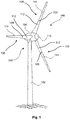
- Fig. 1 shows a wind energy installation 100 with a tower 102 and a nacelle 104.
- a rotor 106 with three rotor blades 108 and a spinner 110 is arranged on the nacelle 104.
- the rotor 106 is set in rotation by the wind during operation and thereby drives a generator in the nacelle 104.
- the spinner 110 envelops a rotor hub (not shown) of the rotor 106.
- the rotor blades 108 are each divided into two parts and have a separation point 109. At the separation point 109, a rotor blade section 112 facing the blade connection and a rotor blade section 114 facing away from the blade connection abut one another. A rotor blade 108 is essentially formed by the rotor blade section 112 facing the blade connection and the rotor blade section 114 facing away from the blade connection. In preferred In variants of the rotor blades 108, there is also the possibility of providing two or more separation points 109 per rotor blade 108.
- Split rotor blades 108 are easier to transport than undivided rotor blades 108 and also offer advantages in production, for example through the use of winding technology.
- the rotor blade sections 112 facing the blade connection are produced by means of the winding technique, which enables fast and inexpensive production.
- a known disadvantage of rotor blades 108 divided in this way is the generally higher total mass of rotor blade 108 compared to undivided rotor blades of similar dimensions.
- the rotor blade section 114 facing away from the blade connection has a low weight.
- the rotor blade section 112 facing the blade connection and the rotor blade section 114 remote from the blade connection can, for example, be connected to one another on the inside of the blade, with screw connections being preferred in particular. So that such a connection can be implemented in practice, it is particularly preferred that the rotor blade 108 has a rotor blade thickness of 1.7 to 1.8 meters at the separation point 109.
- the rotor blade thickness the following description of the Fig. 3 referenced.
- the expansion in the interior of the rotor blade in the direction of the rotor blade density is preferably 1.7 m or more in order to enable simple assembly.
- the rotor blades 108 were preferably designed with a development index.
- the development index results from the gradient of a depth ratio in the direction of the relative leaf length.
- the depth ratio results from the variable profile depth to the separation point profile depth.
- a rotor blade 108 has a profile depth profile which has a sharp decrease in the profile depth in the region of the separation point. This makes it possible to obtain a rotor blade which appropriately takes into account both the system loads to be expected, the aerodynamic effectiveness, and also the total mass of the rotor blade 108 as a whole.
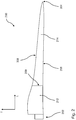
- Fig. 2 shows an exemplary and schematic representation of a further preferred embodiment of a rotor blade 200.
- the rotor blade 200 extends extends in the longitudinal direction L from a blade connection 202 to a blade tip 204.
- it is a two-part rotor blade which has a separation point 209.
- the section of the rotor blade 200 which adjoins the separation point 209 and the blade connection 202 or comprises the blade connection 202 is the rotor blade section 212 facing the blade connection.
- the further rotor blade section which faces away from the blade connection and adjoins the blade tip 204 or the blade tip 204 comprises the rotor blade section 214 facing away from the blade connection.
- the rotor blade In the direction of the profile depth T, the rotor blade extends from a leading edge 206 to a trailing edge 208.
- the profile depth generally corresponds to the spacing from the leading edge 206 to the trailing edge 208 Fig. 2 it can for example be one of the rotor blades 108 of the Fig. 1 Act.
- the in Fig. 3 The cross section shown of the rotor blade 200 represents a cross section in the region of the separation point.
- the profile depth prevailing at the separation point is the separation point profile depth 210.
- the rotor blade Due to the corresponding geometric design of the rotor blade 200, the rotor blade has a suction side 216 and a pressure side 218.
- the rotor blade thickness D runs orthogonally to the direction of the profile depth T of the rotor blade 200 and the longitudinal direction L of the rotor blade 200 Fig. 3
- the shown example of the rotor blade 200 also find profiles with blunt or thick rear edges, so-called flatback profiles, use.
- the course of the depth ratio 300 in Fig. 4 shows a decreasing course along the longitudinal direction of the rotor blade from the blade connection to the blade tip.
- the longitudinal extension of the rotor blade in the longitudinal direction is shown in a standardized representation, so that a relative blade length of the rotor blade based on the blade connection is shown in a blade length value range between 0% and 100%.
- the depth ratio in an area 310 of the separation point is equal to 1 in the area of a relative blade length of approx. 28%.
- T Cutting point is the profile depth at the cutting point.
- a first profile 330 represents the profile of a first development measure for a conventional, one-piece rotor blade.
- the depth ratio the gradient of which in the direction of the relative blade length is defined as the development index E, is for the first curve 330 in the absence of an actual separation point in a one-piece rotor blade as the ratio of the variable profile depth and the profile depth at a hypothetical separation point in the range of a relative blade length defined by about 0.3.
- the second profile 350 represents a profile of a second development dimension of a rotor blade according to the invention.
- the development index in the region of the separation point lies in a dimension index value range between -3 and -1.
- the development index in the area of the separation point lies in a dimension index value range between -2.4 and -2.0.
- the development index shows an increasing value.
- the development index in the blade length range between 25% and 50%, in particular in the blade length range between 32% and 40%, is less than -1.
- the second curve 350 also has a curve such that in the sheet length value range between 60% and 80% the development index lies in the dimension index value range between -1.1 and -0.5.
- the value of the development index also decreases from the relative sheet length of 20%, in particular from 25%, towards the separation point. Furthermore, the development index increases from the separation point to the relative sheet length of 90%.
Landscapes
- Engineering & Computer Science (AREA)
- Life Sciences & Earth Sciences (AREA)
- Sustainable Development (AREA)
- Sustainable Energy (AREA)
- Chemical & Material Sciences (AREA)
- Combustion & Propulsion (AREA)
- Mechanical Engineering (AREA)
- General Engineering & Computer Science (AREA)
- Physics & Mathematics (AREA)
- Fluid Mechanics (AREA)
- Wind Motors (AREA)
Applications Claiming Priority (2)
| Application Number | Priority Date | Filing Date | Title |
|---|---|---|---|
| DE102018103732.5A DE102018103732A1 (de) | 2018-02-20 | 2018-02-20 | Rotorblatt für eine Windenergieanlage und Verfahren |
| PCT/EP2019/053226 WO2019162114A1 (de) | 2018-02-20 | 2019-02-11 | Rotorblatt für eine windenergieanlage und verfahren |
Publications (2)
| Publication Number | Publication Date |
|---|---|
| EP3735530A1 EP3735530A1 (de) | 2020-11-11 |
| EP3735530B1 true EP3735530B1 (de) | 2021-12-08 |
Family
ID=65433653
Family Applications (1)
| Application Number | Title | Priority Date | Filing Date |
|---|---|---|---|
| EP19705314.3A Active EP3735530B1 (de) | 2018-02-20 | 2019-02-11 | Rotorblatt für eine windenergieanlage und verfahren |
Country Status (6)
| Country | Link |
|---|---|
| US (1) | US11181092B2 (da) |
| EP (1) | EP3735530B1 (da) |
| CN (1) | CN111742138B (da) |
| DE (1) | DE102018103732A1 (da) |
| DK (1) | DK3735530T3 (da) |
| WO (1) | WO2019162114A1 (da) |
Families Citing this family (1)
| Publication number | Priority date | Publication date | Assignee | Title |
|---|---|---|---|---|
| DE102022104017A1 (de) | 2022-02-21 | 2023-08-24 | Wobben Properties Gmbh | Rotorblatt einer Windenergieanlage |
Family Cites Families (17)
| Publication number | Priority date | Publication date | Assignee | Title |
|---|---|---|---|---|
| FR1187166A (fr) | 1957-11-14 | 1959-09-08 | Perfectionnements apportés aux machines à pales, notamment aux éoliennes | |
| ATE534817T1 (de) * | 2004-06-30 | 2011-12-15 | Vestas Wind Sys As | Aus zwei getrennten teilen hergestellte windturbinenflügel |
| EP1978245A1 (en) * | 2007-04-04 | 2008-10-08 | Siemens Aktiengesellschaft | Optimised layout for wind turbine rotor blades |
| ES2542869T3 (es) * | 2009-01-27 | 2015-08-12 | Vestas Wind Systems A/S | Pala de turbina eólica dividida en secciones |
| EP2795105B1 (en) * | 2011-12-22 | 2021-02-17 | LM WP Patent Holding A/S | Wind turbine blade assembled from inboard part and outboard part having different types of load carrying structures |
| IN2012DE00573A (da) * | 2012-02-29 | 2015-06-05 | Gen Electric | |
| DE102012206109C5 (de) * | 2012-04-13 | 2022-06-09 | Wobben Properties Gmbh | Rotorblatt einer Windenergieanlage |
| DK201270670A (en) * | 2012-10-31 | 2014-05-01 | Envision Energy Denmark Aps | Wind turbine with an offset suction side |
| ES2510893B1 (es) * | 2013-04-19 | 2015-09-11 | Aeroblade, S.A. | Pala eólica modular, método de unión, y aerogenerador |
| JP6167051B2 (ja) * | 2014-02-21 | 2017-07-19 | 三菱重工業株式会社 | 風車翼、風車ロータ及び風力発電装置 |
| DE102014206670A1 (de) | 2014-04-07 | 2015-10-08 | Wobben Properties Gmbh | Rotorblatt einer Windenergieanlage |
| DE102015116634A1 (de) * | 2015-10-01 | 2017-04-06 | Wobben Properties Gmbh | Windenergieanlagen-Rotorblatt und Windenergieanlage |
| DE102016201114A1 (de) | 2016-01-26 | 2017-07-27 | Wobben Properties Gmbh | Rotorblatt einer Windenergieanlage und Windenergieanlage |
| EP3631194B1 (en) * | 2017-05-22 | 2024-04-17 | LM Wind Power A/S | Wind turbine blade and method of assembly of blade elements to form a wind turbine blade |
| DE102017124861A1 (de) * | 2017-10-24 | 2019-04-25 | Wobben Properties Gmbh | Rotorblatt einer Windenergieanlage und Verfahren zu dessen Auslegung |
| DK3581790T3 (en) * | 2018-06-14 | 2025-10-27 | Siemens Gamesa Renewable Energy As | Wind turbine rotor blade |
| EP3855014B1 (de) * | 2020-01-22 | 2025-05-21 | Nordex Energy SE & Co. KG | Geteiltes rotorblatt einer windenergieanlage sowie rotorblattsegment |
-
2018
- 2018-02-20 DE DE102018103732.5A patent/DE102018103732A1/de active Pending
-
2019
- 2019-02-11 DK DK19705314.3T patent/DK3735530T3/da active
- 2019-02-11 EP EP19705314.3A patent/EP3735530B1/de active Active
- 2019-02-11 CN CN201980014389.6A patent/CN111742138B/zh active Active
- 2019-02-11 WO PCT/EP2019/053226 patent/WO2019162114A1/de not_active Ceased
- 2019-02-11 US US16/970,586 patent/US11181092B2/en active Active
Also Published As
| Publication number | Publication date |
|---|---|
| US11181092B2 (en) | 2021-11-23 |
| US20210108609A1 (en) | 2021-04-15 |
| EP3735530A1 (de) | 2020-11-11 |
| DK3735530T3 (da) | 2022-01-03 |
| WO2019162114A1 (de) | 2019-08-29 |
| DE102018103732A1 (de) | 2019-08-22 |
| CN111742138A (zh) | 2020-10-02 |
| CN111742138B (zh) | 2023-10-24 |
Similar Documents
| Publication | Publication Date | Title |
|---|---|---|
| EP1514023B1 (de) | Windenergieanlage | |
| DE102012206109B3 (de) | Rotorblatt einer Windenergieanlage | |
| EP3926162B1 (de) | Verfahren zum betrieb einer windenergieanlage, steuerungsvorrichtung zum betrieb einer windenergieanlage und windpark | |
| EP2280163B1 (de) | Windenergieanlage sowie Rotorblatt für eine Windenergieanlage | |
| EP3665384B1 (de) | Rotorblatt eines rotors einer windenergieanlage, windenergieanlage und verfahren zur verbesserung des wirkungsgrades eines rotors einer windenergieanlage | |
| EP3701143B1 (de) | Rotorblatt einer windenergieanlage und verfahren zu dessen auslegung | |
| WO2016009037A1 (de) | Windenergieanlagen-rotorblatt, rotorblatthinterkante, und verfahren zum herstellen eines windenergieanlagen-rotorblattes, und windenergieanlage | |
| EP3855014A1 (de) | Geteiltes rotorblatt einer windenergieanlage sowie rotorblattsegment | |
| EP3066337B1 (de) | Rotorblatt einer windenergieanlage und windenergieanlage | |
| EP2715117A1 (de) | Rotor mit einem gekrümmten rotorblatt für eine windkraftanlage | |
| EP3510275B1 (de) | Windenergieanlagen-rotorblatt | |
| EP3147499B1 (de) | Rotorblatt mit einem schalloptimierten profil sowie verfahren zum herstellen eines rotorblatts | |
| EP3963204B1 (de) | Rotor für eine windenergieanlage und windenergieanlage | |
| EP3824176B1 (de) | Rotorblatt für eine windenergieanlage und windenergieanlage | |
| EP3399183B1 (de) | Rotorblatt einer windenergieanlage | |
| EP3735530B1 (de) | Rotorblatt für eine windenergieanlage und verfahren | |
| EP3969743B1 (de) | Rotorblatt und verfahren zum auslegen eines rotorblatts einer windenergieanlage. | |
| EP3844384B1 (de) | Rotor mit rotorblatt, windenergieanlage und verfahren zum optimieren einer windenergieanlage | |
| EP3969741B1 (de) | Rotorblatt und windenergieanlage | |
| EP2492496B1 (de) | Windenergieanlagenrotorblatt mit variierender Blattiefe | |
| EP3280910A1 (de) | Windenergieanlagen-rotorblatt | |
| EP3604796A1 (de) | Rotorblatt für eine windenergieanlage, windenergieanlage, verfahren zum verlängern eines rotorblatts sowie verfahren zum herstellen eines rotorblatts | |
| EP4703582A1 (de) | Rotorblatt, verfahren und windenergieanlage | |
| WO2018007403A1 (de) | Rotorblatt und rotor für windkraftanlagen im megawatt-bereich |
Legal Events
| Date | Code | Title | Description |
|---|---|---|---|
| STAA | Information on the status of an ep patent application or granted ep patent |
Free format text: STATUS: UNKNOWN |
|
| STAA | Information on the status of an ep patent application or granted ep patent |
Free format text: STATUS: THE INTERNATIONAL PUBLICATION HAS BEEN MADE |
|
| PUAI | Public reference made under article 153(3) epc to a published international application that has entered the european phase |
Free format text: ORIGINAL CODE: 0009012 |
|
| STAA | Information on the status of an ep patent application or granted ep patent |
Free format text: STATUS: REQUEST FOR EXAMINATION WAS MADE |
|
| 17P | Request for examination filed |
Effective date: 20200805 |
|
| AK | Designated contracting states |
Kind code of ref document: A1 Designated state(s): AL AT BE BG CH CY CZ DE DK EE ES FI FR GB GR HR HU IE IS IT LI LT LU LV MC MK MT NL NO PL PT RO RS SE SI SK SM TR |
|
| AX | Request for extension of the european patent |
Extension state: BA ME |
|
| STAA | Information on the status of an ep patent application or granted ep patent |
Free format text: STATUS: EXAMINATION IS IN PROGRESS |
|
| 17Q | First examination report despatched |
Effective date: 20201215 |
|
| DAV | Request for validation of the european patent (deleted) | ||
| DAX | Request for extension of the european patent (deleted) | ||
| GRAP | Despatch of communication of intention to grant a patent |
Free format text: ORIGINAL CODE: EPIDOSNIGR1 |
|
| STAA | Information on the status of an ep patent application or granted ep patent |
Free format text: STATUS: GRANT OF PATENT IS INTENDED |
|
| INTG | Intention to grant announced |
Effective date: 20210721 |
|
| GRAS | Grant fee paid |
Free format text: ORIGINAL CODE: EPIDOSNIGR3 |
|
| GRAA | (expected) grant |
Free format text: ORIGINAL CODE: 0009210 |
|
| STAA | Information on the status of an ep patent application or granted ep patent |
Free format text: STATUS: THE PATENT HAS BEEN GRANTED |
|
| AK | Designated contracting states |
Kind code of ref document: B1 Designated state(s): AL AT BE BG CH CY CZ DE DK EE ES FI FR GB GR HR HU IE IS IT LI LT LU LV MC MK MT NL NO PL PT RO RS SE SI SK SM TR |
|
| REG | Reference to a national code |
Ref country code: GB Ref legal event code: FG4D Free format text: NOT ENGLISH |
|
| REG | Reference to a national code |
Ref country code: AT Ref legal event code: REF Ref document number: 1453968 Country of ref document: AT Kind code of ref document: T Effective date: 20211215 Ref country code: CH Ref legal event code: EP |
|
| REG | Reference to a national code |
Ref country code: DE Ref legal event code: R096 Ref document number: 502019002968 Country of ref document: DE |
|
| REG | Reference to a national code |
Ref country code: DK Ref legal event code: T3 Effective date: 20211223 |
|
| REG | Reference to a national code |
Ref country code: IE Ref legal event code: FG4D Free format text: LANGUAGE OF EP DOCUMENT: GERMAN |
|
| REG | Reference to a national code |
Ref country code: NL Ref legal event code: FP |
|
| REG | Reference to a national code |
Ref country code: LT Ref legal event code: MG9D |
|
| PG25 | Lapsed in a contracting state [announced via postgrant information from national office to epo] |
Ref country code: RS Free format text: LAPSE BECAUSE OF FAILURE TO SUBMIT A TRANSLATION OF THE DESCRIPTION OR TO PAY THE FEE WITHIN THE PRESCRIBED TIME-LIMIT Effective date: 20211208 Ref country code: LT Free format text: LAPSE BECAUSE OF FAILURE TO SUBMIT A TRANSLATION OF THE DESCRIPTION OR TO PAY THE FEE WITHIN THE PRESCRIBED TIME-LIMIT Effective date: 20211208 Ref country code: FI Free format text: LAPSE BECAUSE OF FAILURE TO SUBMIT A TRANSLATION OF THE DESCRIPTION OR TO PAY THE FEE WITHIN THE PRESCRIBED TIME-LIMIT Effective date: 20211208 Ref country code: BG Free format text: LAPSE BECAUSE OF FAILURE TO SUBMIT A TRANSLATION OF THE DESCRIPTION OR TO PAY THE FEE WITHIN THE PRESCRIBED TIME-LIMIT Effective date: 20220308 |
|
| PG25 | Lapsed in a contracting state [announced via postgrant information from national office to epo] |
Ref country code: SE Free format text: LAPSE BECAUSE OF FAILURE TO SUBMIT A TRANSLATION OF THE DESCRIPTION OR TO PAY THE FEE WITHIN THE PRESCRIBED TIME-LIMIT Effective date: 20211208 Ref country code: NO Free format text: LAPSE BECAUSE OF FAILURE TO SUBMIT A TRANSLATION OF THE DESCRIPTION OR TO PAY THE FEE WITHIN THE PRESCRIBED TIME-LIMIT Effective date: 20220308 Ref country code: LV Free format text: LAPSE BECAUSE OF FAILURE TO SUBMIT A TRANSLATION OF THE DESCRIPTION OR TO PAY THE FEE WITHIN THE PRESCRIBED TIME-LIMIT Effective date: 20211208 Ref country code: HR Free format text: LAPSE BECAUSE OF FAILURE TO SUBMIT A TRANSLATION OF THE DESCRIPTION OR TO PAY THE FEE WITHIN THE PRESCRIBED TIME-LIMIT Effective date: 20211208 Ref country code: GR Free format text: LAPSE BECAUSE OF FAILURE TO SUBMIT A TRANSLATION OF THE DESCRIPTION OR TO PAY THE FEE WITHIN THE PRESCRIBED TIME-LIMIT Effective date: 20220309 |
|
| PG25 | Lapsed in a contracting state [announced via postgrant information from national office to epo] |
Ref country code: SM Free format text: LAPSE BECAUSE OF FAILURE TO SUBMIT A TRANSLATION OF THE DESCRIPTION OR TO PAY THE FEE WITHIN THE PRESCRIBED TIME-LIMIT Effective date: 20211208 Ref country code: SK Free format text: LAPSE BECAUSE OF FAILURE TO SUBMIT A TRANSLATION OF THE DESCRIPTION OR TO PAY THE FEE WITHIN THE PRESCRIBED TIME-LIMIT Effective date: 20211208 Ref country code: RO Free format text: LAPSE BECAUSE OF FAILURE TO SUBMIT A TRANSLATION OF THE DESCRIPTION OR TO PAY THE FEE WITHIN THE PRESCRIBED TIME-LIMIT Effective date: 20211208 Ref country code: PT Free format text: LAPSE BECAUSE OF FAILURE TO SUBMIT A TRANSLATION OF THE DESCRIPTION OR TO PAY THE FEE WITHIN THE PRESCRIBED TIME-LIMIT Effective date: 20220408 Ref country code: ES Free format text: LAPSE BECAUSE OF FAILURE TO SUBMIT A TRANSLATION OF THE DESCRIPTION OR TO PAY THE FEE WITHIN THE PRESCRIBED TIME-LIMIT Effective date: 20211208 Ref country code: EE Free format text: LAPSE BECAUSE OF FAILURE TO SUBMIT A TRANSLATION OF THE DESCRIPTION OR TO PAY THE FEE WITHIN THE PRESCRIBED TIME-LIMIT Effective date: 20211208 Ref country code: CZ Free format text: LAPSE BECAUSE OF FAILURE TO SUBMIT A TRANSLATION OF THE DESCRIPTION OR TO PAY THE FEE WITHIN THE PRESCRIBED TIME-LIMIT Effective date: 20211208 |
|
| PG25 | Lapsed in a contracting state [announced via postgrant information from national office to epo] |
Ref country code: PL Free format text: LAPSE BECAUSE OF FAILURE TO SUBMIT A TRANSLATION OF THE DESCRIPTION OR TO PAY THE FEE WITHIN THE PRESCRIBED TIME-LIMIT Effective date: 20211208 |
|
| REG | Reference to a national code |
Ref country code: DE Ref legal event code: R026 Ref document number: 502019002968 Country of ref document: DE |
|
| PLBI | Opposition filed |
Free format text: ORIGINAL CODE: 0009260 |
|
| PLAX | Notice of opposition and request to file observation + time limit sent |
Free format text: ORIGINAL CODE: EPIDOSNOBS2 |
|
| PG25 | Lapsed in a contracting state [announced via postgrant information from national office to epo] |
Ref country code: MC Free format text: LAPSE BECAUSE OF FAILURE TO SUBMIT A TRANSLATION OF THE DESCRIPTION OR TO PAY THE FEE WITHIN THE PRESCRIBED TIME-LIMIT Effective date: 20211208 Ref country code: IS Free format text: LAPSE BECAUSE OF FAILURE TO SUBMIT A TRANSLATION OF THE DESCRIPTION OR TO PAY THE FEE WITHIN THE PRESCRIBED TIME-LIMIT Effective date: 20220408 |
|
| 26 | Opposition filed |
Opponent name: SIEMENS GAMESA RENEWABLE ENERGY GMBH & CO. KG Effective date: 20220906 |
|
| REG | Reference to a national code |
Ref country code: CH Ref legal event code: PL |
|
| REG | Reference to a national code |
Ref country code: BE Ref legal event code: MM Effective date: 20220228 |
|
| PG25 | Lapsed in a contracting state [announced via postgrant information from national office to epo] |
Ref country code: LU Free format text: LAPSE BECAUSE OF NON-PAYMENT OF DUE FEES Effective date: 20220211 Ref country code: AL Free format text: LAPSE BECAUSE OF FAILURE TO SUBMIT A TRANSLATION OF THE DESCRIPTION OR TO PAY THE FEE WITHIN THE PRESCRIBED TIME-LIMIT Effective date: 20211208 |
|
| PG25 | Lapsed in a contracting state [announced via postgrant information from national office to epo] |
Ref country code: SI Free format text: LAPSE BECAUSE OF FAILURE TO SUBMIT A TRANSLATION OF THE DESCRIPTION OR TO PAY THE FEE WITHIN THE PRESCRIBED TIME-LIMIT Effective date: 20211208 |
|
| PLBB | Reply of patent proprietor to notice(s) of opposition received |
Free format text: ORIGINAL CODE: EPIDOSNOBS3 |
|
| PG25 | Lapsed in a contracting state [announced via postgrant information from national office to epo] |
Ref country code: LI Free format text: LAPSE BECAUSE OF NON-PAYMENT OF DUE FEES Effective date: 20220228 Ref country code: IE Free format text: LAPSE BECAUSE OF NON-PAYMENT OF DUE FEES Effective date: 20220211 Ref country code: CH Free format text: LAPSE BECAUSE OF NON-PAYMENT OF DUE FEES Effective date: 20220228 |
|
| PG25 | Lapsed in a contracting state [announced via postgrant information from national office to epo] |
Ref country code: BE Free format text: LAPSE BECAUSE OF NON-PAYMENT OF DUE FEES Effective date: 20220228 |
|
| PG25 | Lapsed in a contracting state [announced via postgrant information from national office to epo] |
Ref country code: IT Free format text: LAPSE BECAUSE OF FAILURE TO SUBMIT A TRANSLATION OF THE DESCRIPTION OR TO PAY THE FEE WITHIN THE PRESCRIBED TIME-LIMIT Effective date: 20211208 |
|
| PG25 | Lapsed in a contracting state [announced via postgrant information from national office to epo] |
Ref country code: MK Free format text: LAPSE BECAUSE OF FAILURE TO SUBMIT A TRANSLATION OF THE DESCRIPTION OR TO PAY THE FEE WITHIN THE PRESCRIBED TIME-LIMIT Effective date: 20211208 Ref country code: CY Free format text: LAPSE BECAUSE OF FAILURE TO SUBMIT A TRANSLATION OF THE DESCRIPTION OR TO PAY THE FEE WITHIN THE PRESCRIBED TIME-LIMIT Effective date: 20211208 |
|
| PG25 | Lapsed in a contracting state [announced via postgrant information from national office to epo] |
Ref country code: HU Free format text: LAPSE BECAUSE OF FAILURE TO SUBMIT A TRANSLATION OF THE DESCRIPTION OR TO PAY THE FEE WITHIN THE PRESCRIBED TIME-LIMIT; INVALID AB INITIO Effective date: 20190211 |
|
| PG25 | Lapsed in a contracting state [announced via postgrant information from national office to epo] |
Ref country code: MT Free format text: LAPSE BECAUSE OF FAILURE TO SUBMIT A TRANSLATION OF THE DESCRIPTION OR TO PAY THE FEE WITHIN THE PRESCRIBED TIME-LIMIT Effective date: 20211208 |
|
| APAH | Appeal reference modified |
Free format text: ORIGINAL CODE: EPIDOSCREFNO |
|
| APBP | Date of receipt of notice of appeal recorded |
Free format text: ORIGINAL CODE: EPIDOSNNOA2O |
|
| REG | Reference to a national code |
Ref country code: AT Ref legal event code: MM01 Ref document number: 1453968 Country of ref document: AT Kind code of ref document: T Effective date: 20240211 |
|
| PG25 | Lapsed in a contracting state [announced via postgrant information from national office to epo] |
Ref country code: AT Free format text: LAPSE BECAUSE OF NON-PAYMENT OF DUE FEES Effective date: 20240211 |
|
| APBQ | Date of receipt of statement of grounds of appeal recorded |
Free format text: ORIGINAL CODE: EPIDOSNNOA3O |
|
| PLAB | Opposition data, opponent's data or that of the opponent's representative modified |
Free format text: ORIGINAL CODE: 0009299OPPO |
|
| R26 | Opposition filed (corrected) |
Opponent name: SIEMENS GAMESA RENEWABLE ENERGY DEUTSCHLAND GMBH Effective date: 20220906 |
|
| PG25 | Lapsed in a contracting state [announced via postgrant information from national office to epo] |
Ref country code: TR Free format text: LAPSE BECAUSE OF FAILURE TO SUBMIT A TRANSLATION OF THE DESCRIPTION OR TO PAY THE FEE WITHIN THE PRESCRIBED TIME-LIMIT Effective date: 20211208 |
|
| PGFP | Annual fee paid to national office [announced via postgrant information from national office to epo] |
Ref country code: NL Payment date: 20260218 Year of fee payment: 8 |
|
| PGFP | Annual fee paid to national office [announced via postgrant information from national office to epo] |
Ref country code: GB Payment date: 20260219 Year of fee payment: 8 |
|
| PGFP | Annual fee paid to national office [announced via postgrant information from national office to epo] |
Ref country code: DE Payment date: 20260302 Year of fee payment: 8 Ref country code: DK Payment date: 20260217 Year of fee payment: 8 |
|
| PGFP | Annual fee paid to national office [announced via postgrant information from national office to epo] |
Ref country code: AT Payment date: 20260410 Year of fee payment: 5 |
|
| PGFP | Annual fee paid to national office [announced via postgrant information from national office to epo] |
Ref country code: FR Payment date: 20260219 Year of fee payment: 8 |