EP3734399A1 - Lever device and working machine with same - Google Patents
Lever device and working machine with same Download PDFInfo
- Publication number
- EP3734399A1 EP3734399A1 EP18893504.3A EP18893504A EP3734399A1 EP 3734399 A1 EP3734399 A1 EP 3734399A1 EP 18893504 A EP18893504 A EP 18893504A EP 3734399 A1 EP3734399 A1 EP 3734399A1
- Authority
- EP
- European Patent Office
- Prior art keywords
- lever
- lateral shaft
- cam
- guide pin
- groove portion
- Prior art date
- Legal status (The legal status is an assumption and is not a legal conclusion. Google has not performed a legal analysis and makes no representation as to the accuracy of the status listed.)
- Granted
Links
Images






Classifications
-
- E—FIXED CONSTRUCTIONS
- E02—HYDRAULIC ENGINEERING; FOUNDATIONS; SOIL SHIFTING
- E02F—DREDGING; SOIL-SHIFTING
- E02F9/00—Component parts of dredgers or soil-shifting machines, not restricted to one of the kinds covered by groups E02F3/00 - E02F7/00
- E02F9/16—Cabins, platforms, or the like, for drivers
- E02F9/166—Cabins, platforms, or the like, for drivers movable, tiltable or pivoting, e.g. movable seats, dampening arrangements of cabins
-
- E—FIXED CONSTRUCTIONS
- E02—HYDRAULIC ENGINEERING; FOUNDATIONS; SOIL SHIFTING
- E02F—DREDGING; SOIL-SHIFTING
- E02F9/00—Component parts of dredgers or soil-shifting machines, not restricted to one of the kinds covered by groups E02F3/00 - E02F7/00
- E02F9/20—Drives; Control devices
- E02F9/2004—Control mechanisms, e.g. control levers
-
- E—FIXED CONSTRUCTIONS
- E02—HYDRAULIC ENGINEERING; FOUNDATIONS; SOIL SHIFTING
- E02F—DREDGING; SOIL-SHIFTING
- E02F9/00—Component parts of dredgers or soil-shifting machines, not restricted to one of the kinds covered by groups E02F3/00 - E02F7/00
- E02F9/16—Cabins, platforms, or the like, for drivers
-
- F—MECHANICAL ENGINEERING; LIGHTING; HEATING; WEAPONS; BLASTING
- F16—ENGINEERING ELEMENTS AND UNITS; GENERAL MEASURES FOR PRODUCING AND MAINTAINING EFFECTIVE FUNCTIONING OF MACHINES OR INSTALLATIONS; THERMAL INSULATION IN GENERAL
- F16H—GEARING
- F16H25/00—Gearings comprising primarily only cams, cam-followers and screw-and-nut mechanisms
- F16H25/18—Gearings comprising primarily only cams, cam-followers and screw-and-nut mechanisms for conveying or interconverting oscillating or reciprocating motions
-
- G—PHYSICS
- G05—CONTROLLING; REGULATING
- G05G—CONTROL DEVICES OR SYSTEMS INSOFAR AS CHARACTERISED BY MECHANICAL FEATURES ONLY
- G05G1/00—Controlling members, e.g. knobs or handles; Assemblies or arrangements thereof; Indicating position of controlling members
- G05G1/04—Controlling members for hand actuation by pivoting movement, e.g. levers
-
- E—FIXED CONSTRUCTIONS
- E02—HYDRAULIC ENGINEERING; FOUNDATIONS; SOIL SHIFTING
- E02F—DREDGING; SOIL-SHIFTING
- E02F9/00—Component parts of dredgers or soil-shifting machines, not restricted to one of the kinds covered by groups E02F3/00 - E02F7/00
- E02F9/20—Drives; Control devices
- E02F9/22—Hydraulic or pneumatic drives
- E02F9/2264—Arrangements or adaptations of elements for hydraulic drives
- E02F9/2271—Actuators and supports therefor and protection therefor
Definitions
- a lever device includes: a base pedestal; a movable body pivotally supported by the base pedestal to be rotatable about a first lateral shaft; a lever supported by the movable body to be swingable; a cam body having a cam groove, pivotally supported by the movable body to be rotatable about a second lateral shaft and configured to rotate about the second lateral shaft according to swinging of the lever; a guide pin provided on the base pedestal and inserted to the cam groove; and a first biasing member configured to press the cam body in a direction to rotate the cam body about the second lateral shaft.
- the unload lever 31 can swing between the push-down position where the guide pin 35 is arranged in the upper groove portion 34b and the pull-up position where the guide pin 35 is arranged in the lower groove portion 34c.
- the guide pin 35 is located at the first engaging portion 34d provided in the upper groove portion 34b of the cam groove 34.
- the guide pin 35 is located in the second engaging portion 34e provided in the lower groove portion 34c of the cam groove 34.
- the unload valve has a state in which the operation fluid outputted from the hydraulic pump can be supplied to each of the hydraulic actuators and a state in which the operation fluid cannot be supplied to each of the hydraulic actuators (a state in which the operation fluid outputted from the hydraulic pump is returned to the operation fluid tank without supplying the fluid to the each of the hydraulic actuators), and is switched between the states depending on the position of the unload lever 31.
- the present embodiment explains a configuration in which the operation of the unload valve is electronically controlled.
- the configuration of the present embodiment is not limited to that, and the operation of the unload valve may be mechanically switched, for example.
- FIG. 8 and FIG. 12 are side views showing the state in which the unload lever 31 is located at the push-down position.
- the left control device 22 has the use position (a normal operating position) for allowing operation of the working machine 1, which is shown in FIG. 8 and FIG. 12 .
- the first contact mechanism 41 restricts the control box 26 from rotating downward around the first lateral axis 27, and the left control device 22 is held at the use position.
- the first contact member 41B contacts to the first contact plate 57, so that the left control device 22 is held at the use position.
- the cam body 33 rotates further upward around the second lateral shaft 32.
- the guide pin 35 moves from the intermediate groove portion 34a to the lower groove portion 34c, and is engaged to the second engaging portion 34e. In this manner, as shown in FIG. 14 , the unload lever 31 is located at the pull-up position, and the left control device 22 is located at the upward-rotating position (the avoiding position).
- the first biasing member 51 when the lever device is located at the push-down position, the first biasing member 51 is arranged rearward of the second lateral shaft 32, which is the pivotal fulcrum of the lever.
- the guide pin 35 is pressed against the edge portion of the upper groove portion 34b by the biasing force of the first biasing member 51 to prevent the cam body 33 from rotating upward.
- the cam body 33 cannot be rotated upward unless the lever device is operated, so that it is possible to prevent the movable body from rotating unintentionally upward.
- the lever device having a lever configured to be swung between the push-down position and the pull-up position can be realized with a smaller number of parts than that of the conventional lever device, so that the manufacturing cost can be reduced.
- the number of connector portions between the members can be reduced as compared with the number of connector portions of the conventional lever device, the amount of backlash at the lever tip end can be reduced, and the operability can be improved.
- the first biasing member 51 can be assembled behind the first lateral shaft 27 and the second lateral shaft 32, the assembly difficulty of the first biasing member 51 can be improved.
- the degree of freedom in size of the first biasing member 51 is increased.
- the first biasing member 51 for example, is formed of a spring, it is possible to extend the life of the spring by increasing the number of wiring turns.
- the first biasing member 51 provides a biasing force for rotating the cam body 33 in the direction in which the lever is lowered when the lever is located at the push-down position, and provides a biasing force for rotating the cam body 33 in the direction in which the lever is raised when the lever is located at the pull-up position.
Landscapes
- Engineering & Computer Science (AREA)
- General Engineering & Computer Science (AREA)
- Mining & Mineral Resources (AREA)
- Civil Engineering (AREA)
- Structural Engineering (AREA)
- Mechanical Engineering (AREA)
- Physics & Mathematics (AREA)
- General Physics & Mathematics (AREA)
- Automation & Control Theory (AREA)
- Mechanical Control Devices (AREA)
- Operation Control Of Excavators (AREA)
- Component Parts Of Construction Machinery (AREA)
Abstract
Description
- The present invention relates to a working machine having a lever device and a working machine having the lever device.
- As a working machine provided with a lever device such as an unload lever device, the working machine disclosed in Patent Document 1 is previously known.
- Patent Document 1 discloses a technique for configuring a guide pin provided on the unload lever to engage with a guide groove provided on a support bracket under the state where the unload lever is pulled up (an unloading state), so that it is prevented from shifting to a loading state against the operator's intention when the operator pushes down a portion (the operation lever or the like) other than the unload lever.
- [Patent Document 1] Japanese Unexamined Patent Publication No.
2017-148522 - However, in the technique of Patent Document 1, there is a problem that the manufacturing cost is high due to the large number of parts (1) and the amount of backlash at the lever tip is large and the operability is bad because the number of connector portions between the links is large (2).
- In view of the conventional technique, the present invention intends to provide a lever device that can be manufactured in low cost and has good operability.
- A lever device according to one aspect of the present invention includes: a base pedestal; a movable body pivotally supported by the base pedestal to be rotatable about a first lateral shaft; a lever supported by the movable body to be swingable; a cam body having a cam groove, pivotally supported by the movable body to be rotatable about a second lateral shaft and configured to rotate about the second lateral shaft according to swinging of the lever; a guide pin provided on the base pedestal and inserted to the cam groove; and a first biasing member configured to press the cam body in a direction to rotate the cam body about the second lateral shaft. The cam groove includes: an intermediate groove portion curved to be convex in a direction separating from the first lateral shaft; an upper groove portion communicated with an upper end portion of the intermediate groove portion and curved in the direction separating from the first lateral shaft; and a lower groove portion communicated with a lower end portion of the intermediate groove portion and curved in the direction approaching the first lateral shaft. The lever is configured to swing between: a push-down position at which the guide pin is arranged in the upper groove portion; and a pull-up position at which the guide pin is arranged in the lower groove portion. The cam groove is provided in the cam body in front of the second lateral shaft. The first biasing member has: one end connected to a first connector portion provided on the base pedestal; and the other end connected to a second connector portion provided on the cam body, is arranged behind the second lateral shaft when the lever is located at the push-down position, and is arranged in front of the second lateral shaft when the lever is located at the pull-up position.
- According to the configuration mentioned above, a lever device having a lever configured to be swung between a push-down position and a pull-up position can be provided with a smaller number of parts than that of the conventional lever device, and thus the manufacturing costs can be reduced. In addition, the number of connector portions between the members can be reduced as compared with the number of connector portions of the conventional lever device, and thus the amount of backlash at the tip of the lever can be reduced and the operability can be improved.
-
-
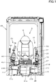
FIG 1 is a front view illustrating a structure of an operating portion of a working machine according to an embodiment of the present invention. -
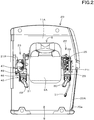
FIG. 2 is a plan view illustrating the structure of the operating portion of the working machine according to the embodiment. -
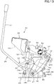
FIG. 3 is a left side view illustrating the structure of the operating portion of the working machine according to the embodiment. -
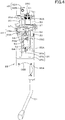
FIG. 4 is a plan view of a left operation device according to the embodiment. -
FIG. 5 is a front view of the left operation device according to the embodiment. -
FIG. 6 is a back view of the left operation device according to the embodiment. -
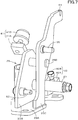
FIG. 7 is a perspective view of a support bracket according to the embodiment. -
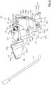
FIG. 8 is a left side view illustrating an inner structure of the left operation device according to the embodiment. -
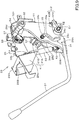
FIG. 9 is a left perspective view illustrating the inner structure of the left operation device according to the embodiment. -
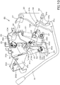
FIG. 10 is an exploded perspective view illustrating the inner structure of the left operation device according to the embodiment. -
FIG. 11 is a right perspective view of the left operation device according to the embodiment. -
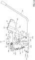
FIG. 12 is a right side view illustrating the inner structure of the left operation device according to the embodiment. -
FIG. 13 is a left side view illustrating a state where the unload lever is pulled up to rotate the left operation device upward according to the embodiment. -
FIG. 14 is a left side view illustrating the unload lever located to the pull-up position according to the embodiment. -
FIG. 15 is a plan view of the working machine according to the embodiment. -
FIG. 16 is a side view of the working machine according to the embodiment. - Hereinafter, an embodiment of the present invention will be described with appropriate reference to the drawings.
-
FIG. 15 andFIG. 16 show the working machine 1 according to the present embodiment. In the present embodiment, a backhoe, which is a swiveling working machine, is shown as the working machine 1. - The working machine 1 includes a machine body (a vehicle body) 2, a
traveling device 3, and aworking device 4. - A
operator seat 8 is provided on themachine body 2. Hereinafter, in the description of the embodiment, the front side of the operator sitting on the operator seat 8 (the left side inFIG. 16 ) is referred to as the front, the rear side of the operator (the right side inFIG. 16 ) is referred to as the rear, the left side of the operator (the front surface side inFIG. 16 ) is referred to as the left, and the right side of the operator (the back surface side inFIG. 16 ) is referred to as the right. In addition, the horizontal direction K1 (seeFIG. 15 ), which is a direction orthogonal to the front-rear direction, will be described as the machine width direction. - The
machine body 2 has aturn base 6 supported on the frame of thetraveling device 3. Theturn base 6 is supported above thetraveling device 3 via a bearing so as to be freely turned around a vertical axis by a driving force of a turn motor (not shown in the drawings). As shown inFIG. 16 , theworking device 4 is attached to the front portion of theturn base 6. Acabin 20 is mounted on theturn base 6. Note that theworking device 4 and thecabin 20 are omitted inFIG. 15 . Theoperator seat 8 is provided inside thecabin 20. Aboarding gate 20a is provided on the left side of thecabin 20, that is, the left of theoperator seat 8. Adoor 20A is provided at theboarding gate 20a. - An engine room is provided at the rear portion of the
turn base 6. An engine E, a hydraulic pump (not shown in the drawings) and the like are arranged in the engine room. The front side of the engine room is separated from theoperator seat 8 by apartition wall 11A. The rear side of the engine room is covered with arear bonnet 10A. The left side of the engine room is covered with aleft cover body 10B. - A tank room is provided to the right portion on the
turn base 6. A operation fluid tank T, a control valve Q, and the like are arranged in the tank room. The left side of the tank room is separated from theoperator seat 8 by apartition wall 11B. The upper side, the front side, and the right side of the tank room are covered with aright cover body 10C. - As shown in
FIG. 16 , theworking device 4 is attached to the front portion of theturn base 6 by anattachment bracket 12 and aswing bracket 13. Theattachment bracket 12 is fixed to the front portion of theturn base 6. Theswing bracket 13 is supported by theattachment bracket 12 so as to be swingable around an axis extending in a vertical direction. Theswing bracket 13 is swung rightward and leftward by a hydraulic swing cylinder. A counterweight W for balancing the weight of the workingdevice 4 is mounted at the rear portion of theturn base 6. - The traveling
device 3 is a crawler type traveling device, and is provided below the right side and the left side of themachine body 2, respectively. The travelingdevice 3 is driven by a hydraulic traveling motor. Adozer 9 is provided to the front portion of the travelingdevice 3. Thedozer 9 is swung upward and downward by a dozer cylinder constituted of a hydraulic cylinder. - The working
device 4 has aboom 14, anarm 15, and a workingtool 16. The workingdevice 4 includes aboom cylinder 17, anarm cylinder 18, and a workingtool cylinder 19 as the driving mechanisms (the hydraulic actuators) for theboom 14 and the like. Theboom cylinder 17, thearm cylinder 18, and the workingtool cylinder 19 are constituted of double-acting hydraulic cylinders. - The
boom 14 is supported by theswing bracket 13 so as to be swingable in a vertical direction. Thearm 15 has a base portion supported by the tip end side of theboom 14 so as to be swingable in the vertical direction. The bucket as the workingtool 16 is attached to the tip end side of thearm 15 so as to be capable of performing the squeezing operation and the dumping operation. - A control portion S is provided on the
turn base 6. As shown inFIG. 15 , the control portion S is separated from the engine room by apartition wall 11A, and is separated from the tank room by apartition wall 11B. Anoperator seat 8 is provided in the control portion S. As shown inFIG. 1 andFIG. 3 , theoperator seat 8 includes aseat 8A that serves as a seating surface and includes asuspension 8B provided below theseat 8A. As shown inFIG. 15 , a left traveling operation lever SL and a right traveling operation lever SR are arranged in front of theoperator seat 8. The travelingdevice 3 provided to the left and the travelingdevice 3 provided to the right can be operated separately or simultaneously through the operation of the left traveling operation lever SL and the right traveling operation lever SR. Pedals and the like are arranged near the right foot and the left foot of theoperator seat 8. - As shown in
FIG. 1 , ancontrol dashboard 21 is provided below theoperator seat 8. As shown inFIG. 1 andFIG. 2 , and the like, aleft control device 22 and aright control device 23 are mounted on thecontrol dashboard 21. Theleft control device 22 is provided on the left side of theoperator seat 8. Theright control device 23 is provided on the right side of theoperator seat 8. - As shown in
FIG. 1 , thecontrol dashboard 21 has anupper surface portion 21A substantially flat, aleft leg portion 21L, and aright leg portion 21R. Ahousing space 21B is formed below theupper surface portion 21A. An air conditioner device and the like are housed in thehousing space 21B. Mounting-base portions upper surface portion 21A. Theoperator seat 8 is mounted on the mounting-base portion 21a. Theleft control device 22 is mounted on the mounting-base portion 21b. Theright control device 23 is mounted on the mounting-base portion 21c. - As shown in
FIG. 1 andFIG. 2 , theright control device 23 has acontrol bracket 45. Thecontrol bracket 45 is provided with aright control valve 46 and adozer operation valve 47. Thecontrol bracket 45 is fixed to the upper portion of the mounting-base portion 21c of thecontrol dashboard 21 by bolts. - The
right control valve 46 can be operated by theright operation lever 48. Thedozer operation valve 47 can be operated by adozer operation lever 49. Theright control valve 46 is a pilot valve for theboom 14 and the workingtool 16, and is configured to control the control valve for theboom cylinder 17 and the workingtool cylinder 19 with theright operation lever 48. Thedozer operation valve 47 is a pilot valve for driving thedozer 9, and is configured to control the control valve for the dozer cylinder with thedozer operation lever 49. - The configurations of the
control dashboard 21 and theright control device 23 are not limited to the configurations illustrated in the drawings. - As shown in
FIG. 3 to FIG. 6 andFIG. 8 to FIG. 11 , theleft control device 22 has amovable body 26, acam body 33, and alever 31. - The
left control device 22 is a lever device of this embodiment. Specifically in the present embodiment, thelever 31 is an unload lever configured to switch the hydraulic actuator of the working machine 1 between an operable state and an inoperable state, and the lever device is an unload lever device including the unload lever. Thus, hereinafter, the lever device will be described as the unload lever device and thelever 31 will be described as the unload lever. However, the lever device is not limited to the unload lever device, and thelever 31 is not limited to the unload lever. - The
movable body 26 is pivotally supported so as to be rotatable about an axis extending in the machine width direction with respect to thebase pedestal 25. In the case of this embodiment, themovable body 26 is a control box, and thebase pedestal 25 is a support bracket. Thus, in the following description, themovable body 26 is a control box, and thebase pedestal 25 is a support bracket. However, themovable body 26 is not limited to the control box, and thebase pedestal 25 is not limited to the support bracket. - As shown in
FIG. 5 to FIG. 7 , the support bracket (the base pedestal) 25 includes a plate-shapedattachment portion 25A arranged horizontally, and includes afirst support portion 25B and asecond support portion 25C both raised from the upper surface of theattachment portion 25A. Theattachment portion 25A is fixed to theupper surface portion 21A of thecontrol dashboard 21 by bolts or the like. Thefirst support portion 25B and thesecond support portion 25C are arranged side by side with an interval in the machine width direction. Thefirst support portion 25B is arranged on an inner side in the machine width direction, and thesecond support portion 25C is arranged on an outer side in the machine width direction. Thefirst support portion 25B and thesecond support portion 25C are connected by aconnector shaft 25D extending in the machine width direction. - The control box (the movable body) 26 has a
left plate member 26a, aright plate member 26b, anattachment plate 26c, and abearing plate 26d, and is formed in a box shape. As shown inFIG. 3 to FIG. 6 andFIG. 11 , and the like, theleft plate member 26a forms a left side wall of thecontrol box 26. For convenience of the description, theleft plate member 26a is shown by an imaginary line (a two-dot chain line) inFIG. 8 andFIG. 12 toFIG. 14 , and theleft plate member 26a is omitted inFIG. 9 andFIG. 10 . As shown inFIG. 9 to FIG. 11 , theright plate member 26b forms the right side wall and the back wall of thecontrol box 26. The rear portion of theleft plate member 26a and the back wall of theright plate member 26b are fixed to each other. As shown inFIG. 4 and the like, theattachment plate 26c is fixed so as to connect the front portion of theleft plate member 26a and the front portion of theright plate member 26b. The clearance between theleft plate member 26a and theright plate member 26b is smaller than the width (a length in the machine width direction) of theattachment plate 26c. As shown inFIG. 9 andFIG. 10 , thebearing plate 26d is fixed to the inner surface (a front surface) of the back wall of theright plate member 26b. The left surface of thebearing plate 26d is opposed to the inner surface (a right surface) of theleft plate member 26a. - As shown in
FIG. 4 andFIG. 5 , anattachment portion 26A of theleft control valve 28 is formed on the upper portion of theattachment plate 26c of thecontrol box 26. As shown inFIG. 3 , theleft control valve 28 is attached to theattachment portion 26A. Theattachment portion 26A has a substantiallysemicircular opening 26B whose right front portion is opened. In this manner, theleft control valve 28 can be attached to theopening 26B of theattachment portion 26A from the front right side, that is, theoperator seat 8 side. Theleft control valve 28 is a pilot valve for the turning and the arm operation, and is operated by aleft operation lever 30. Theleft operation lever 30 is attached to the upper portion of theattachment portion 26A of thecontrol box 26. - As shown in
FIG. 7 and the like, thefirst support portion 25B of thesupport bracket 25 is provided with a firstlateral shaft 27 extending in the horizontal direction (in the machine width direction). As shown inFIG. 10 and the like, aboss portion 26C is fitted on the outer periphery of the firstlateral shaft 27 so as to be rotatable around the firstlateral shaft 27. As shown inFIG. 6 and the like, theboss portion 26C extends in the lateral direction (in the machine width direction) so as to connect theleft plate member 26a of thecontrol box 26 and thebearing plate 26d. In this manner, thecontrol box 26 is supported by thesupport bracket 25 so as to be rotatable (around the first lateral shaft 27) about the firstlateral shaft 27 serving as a fulcrum. As shown inFIG. 8 , theboss portion 26C is provided in the lower rear portion of thecontrol box 26. - As shown in
FIG. 7 and the like, thesecond support portion 25C of thesupport bracket 25 is provided with aguide pin 35 having a shaft axis extending in the machine width direction. Theguide pin 35 extends in the direction (leftward) same as the direction of the firstlateral axis 27 and in parallel with the firstlateral axis 27. As shown inFIG. 8 , theguide pin 35 is located on the upper front side of the firstlateral shaft 27. - As shown in
FIG. 4 andFIG. 8 toFIG. 11 , a secondlateral shaft 32 extending in the lateral direction (in the machine width direction) is provided at the rear portion of thecontrol box 26. The secondlateral shaft 32 is located above and rearward of the firstlateral axis 27, and is parallel to the firstlateral axis 27. As shown inFIG. 8 , theguide pin 35 is located at an intermediate height between the firstlateral shaft 27 and the secondlateral shaft 32. As shown inFIG. 4 andFIG. 8 toFIG. 10 , thecam body 33 is supported on the rear portion of thecontrol box 26 by the secondlateral shaft 32. As shown inFIG. 9 ,FIG. 10 , and the like, theboss portion 32A is fitted on the outer periphery of the secondlateral shaft 32 so as to be rotatable around the secondlateral shaft 32, the base portion (an rear upper portion) of thecam body 33 is fixed to theboss portion 32A. In this manner, thecam body 33 is rotatable about the secondlateral shaft 32. - The
cam body 33 is arranged between thesecond support portion 25C of thesupport bracket 25 and theleft plate member 26a of thecontrol box 26. Thecam body 33 has a flat plate shape, and thecam body 33 is rotatably supported by the secondlateral shaft 32 at the portion near the upper end portion, and extends (expands) downward and forward from the secondlateral shaft 32 under the state where the unloadlever 31 is positioned at the push-down position (seeFIG, 8 ). The base portion (the rear portion) of the unloadlever 31 is fixed to the lower front portion of thecam body 33. - The unload
lever 31 is swingably supported by thecontrol box 26 with thecam body 33, and is swingable around the secondlateral shaft 32. When the unloadlever 31 is swung, all of the hydraulic actuators of the working machine 1 (theboom cylinder 17, thearm cylinder 18, the workingtool cylinder 19, the swing cylinder, the dozer cylinder, the traveling motor, the turn motor, and the hydraulic actuator and the like to be attached to/ detached from the service port) can be operated as to whether or not to supply the operation fluid. However, the unloadlever 31 may be operated as to whether or not to supply the operation fluid to only a part of the hydraulic actuators of the working machine 1 (for example, the hydraulic actuators of the working device 4) through the swinging of the unloadlever 31. - As shown in
FIG. 8 to 10 , thecam body 33 has acam groove 34 formed in a substantially Z-shape from one end side (the secondlateral shaft 32 side) toward the other end side (the unloadlever 31 side). Thecam groove 34 is provided at a position in front of the second lateral shaft 32 (on the unloadlever 31 side) in thecam body 33. Theguide pin 35 is inserted into thecam groove 34 though a cam follower. - The
cam groove 34 is formed in such a length that thecontrol box 26 can be rotated by a required angle (for example, about 50°). Thecam groove 34 has anintermediate groove portion 34a, anupper groove portion 34b, and alower groove portion 34c. Theintermediate groove portion 34a is curved so as to be convex toward the side separating away from the firstlateral axis 27. In the present embodiment, theintermediate groove portion 34a is formed so as to have an arc shape centered on the axial center of the firstlateral shaft 27 under the state where theguide pin 35 is located in theintermediate groove portion 34a (seeFIG. 13 ). Under the state where the unloadlever 31 is in the push-down position (seeFIG. 8 ), theupper groove portion 34b communicates with the upper end portion of theintermediate groove portion 34a, and thelower groove portion 34c communicates with the lower end portion of theintermediate groove portion 34a. In particular, under the state where the unloadlever 31 is in the push-down position, theupper groove portion 34b is located on one side (an upper side) of thecam body 33 with respect to theintermediate groove portion 34a and thelower groove portion 34c, has an arcuate shape centering about the axis of the secondlateral shaft 32, and extends forward and upward from the upper end portion of theintermediate groove 34a. Further, in this state, thelower groove portion 34c is provided on the other side (a lower side) of thecam body 33 with respect to theupper groove portion 34b and theintermediate groove portion 34a, and is formed so as to extend downward from the lower end portion of theintermediate groove portion 34a. Thecam groove 34 is formed in a substantially Z-shape in a side view by theintermediate groove portion 34a, theupper groove portion 34b, and thelower groove portion 34c. The width of thecam groove 34 is slightly larger than the diameter of the guide pin 35 (large enough to allow theguide pin 35 to slide in the cam groove 34) except for a widened portion (a second engaging portion) 34e described later. - As shown in
FIG. 10 and the like, thecam body 33 has a first engagingportion 34d and a secondengaging portion 34e which are engaging portions for engaging theguide pin 35. The firstengaging portion 34d is provided on one end side of thecam groove 34. The secondengaging portion 34e is provided on the other end side of thecam groove 34. - The first
engaging portion 34d is provided at the upper end portion of theupper groove portion 34b of thecam groove 34. As shown inFIG. 8 , theguide pin 35 is engaged to the first engagingportion 34d when the unloadlever 31 is in the push-down position. Theguide pin 35 is engaged to the first engagingportion 34d by the biasing force of the first biasingmember 51, which will be described later. - As shown in
FIG. 8 to FIG. 10 , the secondengaging portion 34e is provided in thelower groove portion 34c of thecam groove 34. The secondengaging portion 34e is constituted of a widened portion formed in thelower groove portion 34c. The widened portion is wider than the other portion of thelower groove portion 34c and the diameter of theguide pin 35, and is formed by expanding the inner edge rear portion of thelower groove portion 34c backward in an arc shape (toward the firstlateral axis 27 side). That is, thecam groove 34 has the secondengaging portion 34e widened toward the firstlateral shaft 27 side on the surface of thelower groove portion 34c on the firstlateral shaft 27 side. As shown inFIG. 14 , theguide pin 35 is engaged to the secondengaging portion 34e when the unloadlever 31 is in the push-up position. The engaging of theguide pin 35 to the secondengaging portion 34e is also performed by the biasing force of the first biasingmember 51. Since the secondengaging portion 34e is constituted of the widened portion, a clearance G is formed between the outer periphery of theguide pin 35 and the inner edge (the front edge) of thelower groove portion 34c under the state where theguide pin 35 is engaged to the secondengaging portion 34e (seeFIG. 14 ). - As shown in
FIG. 8 ,FIG. 13 , andFIG. 14 in sequence, when the unloadlever 31 is pulled up, thecam body 33 rotates upward with the secondlateral shaft 32 as a fulcrum. In accordance with the rotation of thecam body 33, theguide pin 35 relatively moves in thecam groove 34 from theupper groove portion 34b to thelower groove portion 34c through theintermediate groove portion 34a. As shown inFIG. 14 ,FIG. 13 , andFIG. 8 in sequence, when the unloadlever 31 is pushed down, theguide pin 35 relatively moves in thecam groove 34 from thelower groove portion 34c to theupper groove portion 34b through theintermediate groove portion 34a. That is, the unloadlever 31 can swing between the push-down position where theguide pin 35 is arranged in theupper groove portion 34b and the pull-up position where theguide pin 35 is arranged in thelower groove portion 34c. When the unloadlever 31 is in the push-down position (seeFIG. 8 ), theguide pin 35 is located at the first engagingportion 34d provided in theupper groove portion 34b of thecam groove 34. When the unloadlever 31 is in the push-up position (seeFIG. 14 ), theguide pin 35 is located in the secondengaging portion 34e provided in thelower groove portion 34c of thecam groove 34. - As shown in
FIG. 10 andFIG. 11 and the like, astay 37 is fixed to the upper surface of the rear portion (the base portion) of thecam body 33. Thestay 37 is formed in a substantially L-shape in a side view. The upper portion of thestay 37 is configured to contact to astopper 54 fixed to the upper portion of theleft plate member 26a of the control box 26(seeFIG. 4 ,FIG. 6 ,FIG. 11 , and the like). Although thestopper 54 is shown inFIG. 9 , theleft plate member 26a is omitted. - As shown in
FIG. 6 ,FIG. 8 ,FIG. 10 and the like, thesupport bracket 25 and thecam body 33 are connected by the first biasingmember 51 constituted of a tension spring. When the unloadlever 31 is in the push-down position (seeFIG. 8 ), the first biasingmember 51 provides a biasing force to thecam body 33, the biasing force rotating thecam body 33 around the secondlateral shaft 32 in a direction in which the unloadlever 31 is lowered with respect to thecam body 33. In this manner, the first biasingmember 51 engages theguide pin 35 to the first engagingportion 34d with the biasing force applied in the pulling direction. In other words, the first biasingmember 51 applies a biasing force that pushes theguide pin 35 to the edge portion (the first engagingportion 34d) of theupper groove portion 34b when the unloadlever 31 is in the push-down position. In addition, when the unloadlever 31 is in the pull-up position (seeFIG. 14 ), the first biasingmember 51 provides a biasing force to thecam body 33 around the secondlateral shaft 32 in a direction in which the unloadlever 31 is raised with respect to thecam body 33. In this manner, the first biasingmember 51 engages theguide pin 35 to the secondengaging portion 34e by the biasing force applied in the pulling direction. In other words, the first biasingmember 51 applies a biasing force that engages theguide pin 35 to the secondengaging portion 34e when the unloadlever 31 is in the pull-up position. - As shown in
FIG. 7 ,FIG. 10 ,FIG. 12 and the like, thesecond support portion 25C of thesupport bracket 25 has afirst connector portion 61 that connects the one end portion (the upper end portion) of the first biasingmember 51. Thefirst connector portion 61 is provided as a recess portion (a notch) in the rear upper portion of thesecond support portion 25C. As shown inFIG. 6 andFIG. 10 , thecam body 33 has asecond connector portion 62 that connects the other end portion (the lower end portion) of the first biasingmember 51. Thesecond connector portion 62 is a shaft body fixed to the rear lower portion of thecam body 33, and projects from thecam body 33 to the right (toward thefirst support portion 25B side). Thefirst connector portion 61 is provided above and behind thesecond connector portion 62. - As shown in
FIG. 8 , thefirst connector portion 61 and thesecond connector portion 62 are located behind the firstlateral shaft 27 and the secondlateral shaft 32 under the state where the unloadlever 31 is in the push-down position. Thus, the first biasingmember 51 connected to thefirst connector portion 61 and thesecond connector portion 62 is also located behind the firstlateral shaft 27 and the secondlateral shaft 32. In addition, thefirst connector portion 61 and thesecond connector portion 62 are provided above the firstlateral shaft 27 and below the secondlateral shaft 32. In other words, the secondlateral shaft 32 is arranged above thefirst connector portion 61 and thesecond connector portion 62. In addition, the firstlateral axis 27 is arranged below thefirst connector portion 61 and thesecond connector portion 62. In this manner, the first biasingmember 51 is located between the firstlateral shaft 27 and the secondlateral shaft 32 in the vertical direction. In addition, the secondlateral shaft 32, which is a fulcrum of rotation of thecam body 33, is located above thefirst connector portion 61 and thesecond connector portion 62. - As shown in
FIG. 14 , thefirst connector portion 61 and thesecond connector portion 62 are located in front of the secondlateral shaft 32 when the unloadlever 31 is in the pull-up position. Thus, the first biasingmember 51 connected to thefirst connector portion 61 and thesecond connector portion 62 is also located in front of the secondlateral shaft 32. - As shown in
FIG. 9 andFIG. 12 , thesupport bracket 25 and thecontrol box 26 are connected by the second biasingmember 52 constituted of a gas cylinder (a gas spring). Thesecond biasing member 52 provides a biasing force that rotates thecontrol box 26 around the firstlateral shaft 27 in a direction of raising the operation lever (the left operation lever 30). Thesecond biasing member 52 assists the upward rotating operation of the left control device 22 (the control box 26) with use of the biasing force in the stretching direction. - As shown in
FIG. 5 ,FIG. 7 ,FIG. 10 ,FIG. 11 , and the like, thefirst support portion 25B of thesupport bracket 25 has athird connector portion 63 that connects one end portion (the lower end portion) of the second biasingmember 52. Thethird connector portion 63 is a shaft body fixed to the front lower portion of thefirst support portion 25B, and protrudes leftward from thefirst support portion 25B (on thesecond support portion 25C side). Thethird connector portion 63 is located in front of the firstlateral shaft 27. As shown inFIG. 4 ,FIG. 8 ,FIG. 9 , and the like, thecontrol box 26 has afourth connector portion 64 that connects the other end portion (the upper end portion) of the second biasingmember 52. Thefourth connector portion 64 is a shaft body fixed to the front portion of theright plate member 26b of thecontrol box 26, and protrudes leftward from theright plate member 26b. - The widened
portion 34e formed in thelower groove portion 34c of thecam groove 34 has a function of facilitating the assembling of the second biasingmember 52. In assembling the second biasingmember 52, the second biasingmember 52 must be assembled while being shortened against the biasing force (the force to stretch). Thus, the second biasingmember 52 is assembled in the most stretched state (seeFIG. 14 ) so that the degree of shortening is reduced. In that state, thecam body 33 is positioned being rotated upward and theguide pin 35 is located in the lower groove portion 31c, and thus the widenedportion 34e serves as a gap for assembling the second biasingmember 52. In this manner, the second biasingmember 52 can be easily assembled to. - As shown in
FIG. 8 to FIG. 10 , and the like, arotation detector device 55 constituted of a limit switch is provided to an upper portion of thebearing plate 26d of thecontrol box 26. The switching piece provided at the tip end of therotation detector device 55 is engaged with thestay 37. Therotation detector device 55 is connected to the electronic controller portion of the hydraulic circuit. The electronic controller portion operates an unload valve (not shown in the drawings) provided in the hydraulic circuit according to the detected result of therotation detector device 55. That is, the unload valve has a state in which the operation fluid outputted from the hydraulic pump can be supplied to each of the hydraulic actuators and a state in which the operation fluid cannot be supplied to each of the hydraulic actuators (a state in which the operation fluid outputted from the hydraulic pump is returned to the operation fluid tank without supplying the fluid to the each of the hydraulic actuators), and is switched between the states depending on the position of the unloadlever 31. It should be noted that the present embodiment explains a configuration in which the operation of the unload valve is electronically controlled. However, the configuration of the present embodiment is not limited to that, and the operation of the unload valve may be mechanically switched, for example. - As shown in
FIG. 14 , when the unloadlever 31 is pulled up, the front portion of thecam body 33 rotates upward with the secondlateral shaft 32 as a fulcrum, and thestay 37 moves (rotates) backward together with thecam body 33. With the movement of thestay 37, the switching piece of therotation detector device 55 projects. In this manner, the pulling up of the unload lever 31 (the unloading state) is detected, and the operation of each of the hydraulic actuators is disabled. - As shown in
FIG. 11 andFIG. 12 , thefirst support portion 25B of thesupport bracket 25 is provided with afirst contact mechanism 41. Thefirst contact mechanism 41 holds theleft control device 22 at a use position described below (seeFIG. 8 ,FIG. 11 , andFIG. 12 ). Thefirst contact mechanism 41 has anattachment plate 41A fixed to the upper portion of thefirst support portion 25B, and has afirst contact member 41B attached to theattachment plate 41A. Thefirst contact member 41B contacts to thefirst contact plate 57 fixed to theright plate member 26b of thecontrol box 26 when theleft control device 22 is placed at the use position. - As shown in
FIG. 8 andFIG. 12 , asecond contact mechanism 42 is provided above theattachment portion 25A of thesupport bracket 25. Thesecond contact mechanism 42 holds theleft control device 22 at an upward-rotating position described below (at an avoiding position) (seeFIG. 14 ). Thesecond contact mechanism 42 has anattachment plate 42A fixed to the rear portion of theattachment portion 25A, and asecond contact member 42B attached to theattachment plate 42A. Thesecond contact member 42B contacts to thesecond contact plate 56 fixed to theleft plate member 26a of thecontrol box 26 when theleft control device 22 is located at the upward-rotating position (seeFIG. 14 ). - A
rotation mechanism 29 configured to rotate theleft control device 22 is constituted of the firstlateral shaft 27, thecam body 33, the unloadlever 31, therotation detector device 55, thefirst contact mechanism 41, thesecond contact mechanism 42, and the like. 29. When theleft control device 22 is rotated (retracted) upward by therotation mechanism 29, theboarding gate 20a provided on the diagonally left front side of the operator seat 8 (that is, the front side of the left control device 22) is secured widely, and thus theleft control device 22 does not prevent the operator from getting in and out of the vehicle. - Hereinafter, the rotating operation of the
left control device 22 will be described in detail. First, the state in which the unloadlever 31 is located at the push-down position and the state in which the unloadlever 31 is located at the pull-up position will be respectively described, and thereafter, the operation of theleft control device 22 associated with the operation of the unload lever 31 (the push-down operation, the pull-up operation). For simplification of the drawings, only the central axis of the first biasingmember 51 and the second biasingmember 52 is shown by a chain line in some of the drawings. In addition, some of the members unnecessary for the description are omitted. - First, the state in which the unload
lever 31 is located at the push-down position will be described. -
FIG. 8 andFIG. 12 are side views showing the state in which the unloadlever 31 is located at the push-down position. Theleft control device 22 has the use position (a normal operating position) for allowing operation of the working machine 1, which is shown inFIG. 8 andFIG. 12 . At this use position, thefirst contact mechanism 41 restricts thecontrol box 26 from rotating downward around the firstlateral axis 27, and theleft control device 22 is held at the use position. In particular, thefirst contact member 41B contacts to thefirst contact plate 57, so that theleft control device 22 is held at the use position. - As shown in
FIG. 8 , when theleft control device 22 is located at the use position, the unloadlever 31 is prevented from rotating downward (in the counterclockwise direction inFIG. 8 ) due to thestay 37 contacting to thestopper 54. Theguide pin 35 is located in theupper groove portion 34b of thecam body 33. A biasing force is applied to thecam body 33 by the first biasingmember 51 so as to rotate downward (in the counterclockwise direction inFIG. 8 ) about the secondlateral shaft 32. Because of the biasing force applied from the first biasingmember 51, theguide pin 35 falls in the state of being engaged to the first engagingportion 34d of theupper groove portion 34b. In this manner, the upward rotation of thecam body 33 is restricted, so that thesteering box 26 is prevented from naturally rotating upward due to the biasing force of the second biasingmember 52. - At the use position, the unload
lever 31 is located at the unload release position, therotation detector device 55 is turned on, and does not detect the upward rotation of the unloadlever 31. Under the state, each of the hydraulic actuators can be operated. - Next, the state in which the unload
lever 31 is located at the push-up position will be described. -
FIG. 14 shows the state in which the unloadlever 31 is located at the pull-up position. The left control device 22 (the control box 26) has the upward-rotating position (the avoiding position) that is the state shown inFIG. 14 . Theleft control device 22 is held at the upward-rotating position by thesecond contact member 42B of thesecond contact mechanism 42 contacting thesecond contact plate 56 fixed to theleft plate member 26a. At the upward-rotating position, theleft control device 22 is retracted rearward from the use position, so that theboarding gate 20a provided on the diagonally left front side of the operator seat 8 (that is, the front side of the left control device 22) is secured widely. - At the upward-rotating position, the unload
lever 31 is located at the unload position, therotation detector device 55 is turned off, and the unload state by the unloadlever 31 is detected. Under the state, each of the hydraulic actuators becomes inoperable. - At the upward-rotating position, the
guide pin 35 is located in thelower groove portion 34c of thecam body 33. In addition, the biasing force of the first biasingmember 51 supplies an biasing force in a direction of rotating thecam body 33 upward about the second lateral shaft 32 (in the clockwise direction inFIG. 14 ). The biasing force of the first biasingmember 51 brings theguide pin 35 into a state of being engaged to the secondengaging portion 34e (a locked state). Under the locked state, theguide pin 35 cannot be disengaged from the secondengaging portion 34e unless the operator operates the unloadlever 31 to rotate thecam body 33. In this manner, even when the operator pushes down a portion other than the unload lever 31 (theleft operation lever 30, thecontrol box 26, and the like), it is prevented from shifting to the unload-releasing state (the load state) against the operator's intention. - To release the locked state from the state shown in
FIG. 14 , the unloadlever 31 is slightly pushed down against the biasing force of the first biasingmember 51. In this manner, thecam body 33 rotates downward with the secondlateral shaft 32 as a fulcrum. Because of this rotation, theguide pin 35 is disengaged from the secondengaging portion 34e and the locked state is released. When the unloadlever 31 is further pushed down after releasing the locked state, thecam body 33 rotates downward (in the counterclockwise direction inFIG. 14 ) around the secondlateral shaft 32. In accordance with the rotation of thecam body 33, theguide pin 35 moves relative to thecam body 33, and moves in thecam groove 34 from thelower groove portion 34c to theintermediate groove portion 34a. - As shown in
FIG. 13 , when theguide pin 35 moves to theintermediate groove portion 34a, thecontrol box 26 is allowed to rotate downward around the firstlateral shaft 27 because theintermediate groove portion 34a is formed to have an arc groove centered on the axial center of the firstlateral shaft 27, and thus the rotation is started. - When the unload
lever 31 is further pushed down from the state ofFIG. 13 , thecam body 33 rotates further downward around the secondlateral shaft 32. In accordance with the downward rotation of thecam body 33, theguide pin 35 moves to the upper end of theupper groove portion 34b and is locked by the first engagingportion 34d. In this manner, the unloadlever 31 is located at the push-down position as shown inFIG. 8 , and theleft control device 22 is located at the use position. - When the unload
lever 31 is pulled up against the biasing force of the first biasingmember 51 from the state where the unloadlever 31 is located at the push-down position as shown inFIG. 8 , thecam body 33 rotates upward about the second lateral shaft 32 (in the clockwise direction inFIG. 8 ). In accordance with the rotation of thecam body 33, theguide pin 35 moves relative to thecam body 33, and moves in thecam groove 34 from theupper groove portion 34b to theintermediate groove portion 34a. As shown inFIG. 13 , when theguide pin 35 moves to theintermediate groove portion 34a, theintermediate groove portion 34a is formed to have an arc groove centered on the axial center of the firstlateral shaft 27. Thus, the upward rotation of thecontrol box 26 around the firstlateral shaft 27 is allowed, and then the rotation starts. - When the unload
lever 31 is further pulled up from the state ofFIG. 13 , thecam body 33 rotates further upward around the secondlateral shaft 32. In accordance with the upward rotation of thecam body 33, theguide pin 35 moves from theintermediate groove portion 34a to thelower groove portion 34c, and is engaged to the secondengaging portion 34e. In this manner, as shown inFIG. 14 , the unloadlever 31 is located at the pull-up position, and theleft control device 22 is located at the upward-rotating position (the avoiding position). - In the process of operation to pull up the unloading
lever 31, the second biasingmember 52 applies, to thecontrol box 26, a biasing force in the extending direction, and thereby assisting the operation to rotate thecontrol box 26 upward about the firstlateral axis 27. - As described above, the lever device (the left control device 22) according to the embodiment, includes: the base pedestal (the support bracket 25); the movable body (the control box 26) pivotally supported by the base pedestal to be rotatable about the first
lateral shaft 27; the lever (the unload lever 31) supported by the movable body to be swingable; thecam body 33 having thecam groove 34, pivotally supported by the movable body to be rotatable about the secondlateral shaft 32 and configured to rotate about the secondlateral shaft 32 according to the swinging of the lever; theguide pin 35 provided on the base pedestal and inserted to thecam groove 34; and the first biasingmember 51 configured to press thecam body 33 in a direction to rotate thecam body 33 about the secondlateral shaft 32. Thecam groove 34 includes: theintermediate groove portion 34a curved to be convex in a direction separating from the firstlateral shaft 27; theupper groove portion 34b communicated with an upper end portion of the intermediate groove portion34a and curved in the direction separating from the firstlateral shaft 27; and thelower groove portion 34c communicated with a lower end portion of theintermediate groove portion 34a and curved in the direction approaching the firstlateral shaft 27. The lever is configured to swing between: the push-down position at which theguide pin 35 is arranged in theupper groove portion 34b; and the pull-up position at which theguide pin 35 is arranged in thelower groove portion 34c. Thecam groove 34 is provided in thecam body 33 in front of the secondlateral shaft 32. Thefirst biasing member 51 has: one end connected to thefirst connector portion 61 provided on the base pedestal; and the other end connected to thesecond connector portion 62 provided on thecam body 33, is arranged behind the secondlateral shaft 32 when the lever is located at the push-down position, and is arranged in front of the secondlateral shaft 32 when the lever is located at the pull-up position. - According to the configuration described above, when the lever device is located at the push-down position, the first biasing
member 51 is arranged rearward of the secondlateral shaft 32, which is the pivotal fulcrum of the lever. Thus, theguide pin 35 is pressed against the edge portion of theupper groove portion 34b by the biasing force of the first biasingmember 51 to prevent thecam body 33 from rotating upward. In this manner, thecam body 33 cannot be rotated upward unless the lever device is operated, so that it is possible to prevent the movable body from rotating unintentionally upward. In addition, when the lever is located at the pull-up position, the first biasingmember 51 is arranged in front of the secondlateral shaft 32, which is the pivotal fulcrum of the lever, so that the biasing force of the first biasingmember 51 engages theguide pin 35 to thelower groove portion 34c, and thereby the downward rotation of thecam body 33 is prevented. In this manner, thecam body 33 cannot be rotated downward unless the operator operates the lever. Thus, the operator is prevented from carelessly pushing down the portions other than the lever (thecontrol box 26, theleft operation lever 30, and the like), and thus it is possible to prevent the position of the lever from being switched by the pushing down. In addition, the lever device having a lever configured to be swung between the push-down position and the pull-up position can be realized with a smaller number of parts than that of the conventional lever device, so that the manufacturing cost can be reduced. In addition, since the number of connector portions between the members can be reduced as compared with the number of connector portions of the conventional lever device, the amount of backlash at the lever tip end can be reduced, and the operability can be improved. Moreover, since the first biasingmember 51 can be assembled behind the firstlateral shaft 27 and the secondlateral shaft 32, the assembly difficulty of the first biasingmember 51 can be improved. - In addition, the second
lateral shaft 32 is arranged above thefirst connector portion 61 and thesecond connector portion 62. - According to the configuration described above, since the distance between the
first connector portion 61 and thesecond connector portion 62 can be increased, the degree of freedom in size of the first biasingmember 51 is increased. In this manner, when the first biasingmember 51, for example, is formed of a spring, it is possible to extend the life of the spring by increasing the number of wiring turns. - In addition, the first
lateral shaft 32 is arranged below thefirst connector portion 61 and thesecond connector portion 62. - According to the configuration described above, the first biasing
member 51 is arranged above the firstlateral shaft 27 and below the secondlateral shaft 32. Thus, when the movable body rotates around the firstlateral shaft 27, the first biasingmember 51 can be moved to a position rearward of and a position forward of the secondlateral shaft 32, which is the rotation fulcrum of the lever. In this manner, the biasing direction of the first biasingmember 51 can be changed depending on whether the lever is located at the push-down position or at the pull-up position. - In addition, the
cam groove 34 has the engaging portion (the secondengaging portion 34e) that is widened toward the firstlateral shaft 27 side on the surface of thelower groove portion 34c provided on the firstlateral shaft 27 side, and theguide pin 35 is engaged to the engaging portion when the lever is located at the pull-up position. - According to the configuration described above, when the lever is located at the pull-up position, the
guide pin 35 can be engaged to the engaging portion (the secondengaging portion 34e) provided in thelower groove portion 34c by the biasing force of the first biasingmember 51. Thus, thecam body 33 can be prevented from rotating downward. In this manner, the operator is prevented from carelessly pushing down the portions other than the lever, and thus it is possible to prevent the position of the lever from being switched by the pushing down. - In addition, the first biasing
member 51 provides a biasing force to pushes theguide pin 35 to the edge portion of theupper groove portion 34b when the lever is located at the push-down position, and provides a biasing force to engage theguide pin 35 to the engaging portion when the lever is located at the pull-up position. - According to the configuration described above, it is possible to more reliably prevent the position of the lever from being switched due to the operator inadvertently pushing down a portion other than the lever.
- In addition, the first biasing
member 51 provides a biasing force for rotating thecam body 33 in the direction in which the lever is lowered when the lever is located at the push-down position, and provides a biasing force for rotating thecam body 33 in the direction in which the lever is raised when the lever is located at the pull-up position. - According to the configuration described above, it is possible to more reliably prevent the position of the lever from being switched due to the operator inadvertently pushing down a portion other than the lever.
- In addition, the lever device includes the second biasing
member 52 connecting the base pedestal and the movable body, and is configured to provide an biasing force for rotating the movable body in a direction of raising the movable body around the firstlateral axis 27. - According to the configuration described above, the biasing force of the second biasing
member 52 can easily perform the operation to rotate the movable body upward about the firstlateral axis 27. - The working machine 1 according to the present embodiment includes the lever device (the left control device 22) described above.
- According to the configuration described above, it is possible to realize the working machine 1 including the lever device that is inexpensive and has good operability.
- In addition, the working machine 1 includes the
operator seat 6, the hydraulic actuator, and the lever device arranged on the side of theoperator seat 6, and the lever is the unloadlever 31 configured to switch the hydraulic actuator between the operable state and the inoperable state. - According to the configuration described above, it is possible to realize the working machine 1 including the unload
lever 31 that is inexpensive and has good operability. - In the above description, the embodiment of the present invention has been explained. However, all the features of the embodiment disclosed in this application should be considered just as examples, and the embodiment does not restrict the present invention accordingly. A scope of the present invention is shown not in the above-described embodiment but in claims, and is intended to include all modifications within and equivalent to a scope of the claims.
-
- 1
- Working
- 4
- Working device
- 8
- Operator seat
- 22
- Left operation device (Lever device)
- 25
- Support bracket (Base pedestal)
- 26
- Operation box (Movable body)
- 27
- First lateral shaft
- 30
- Operation lever (Left operation lever)
- 31
- Unload lever (Lever)
- 32
- Second lateral shaft
- 33
- Cam body
- 34
- Cam groove
- 34d
- First engaging portion
- 34e
- Second engaging portion (Engaging portion)
- 35
- Guide pin
- 51
- First biasing member
- 52
- Second biasing member
- 61
- First connector portion
- 62
- Second connector portion
Claims (9)
- A lever device comprising:a base pedestal;a movable body pivotally supported by the base pedestal to be rotatable about a first lateral shaft;a lever supported by the movable body to be swingable;a cam body having a cam groove, pivotally supported by the movable body to be rotatable about a second lateral shaft and configured to rotate about the second lateral shaft according to swinging of the lever;a guide pin provided on the base pedestal and inserted to the cam groove; anda first biasing member configured to press the cam body in a direction to rotate the cam body about the second lateral shaft,wherein the cam groove includes:an intermediate groove portion curved to be convex in a direction separating from the first lateral shaft;an upper groove portion communicated with an upper end portion of the intermediate groove portion and curved in the direction separating from the first lateral shaft; anda lower groove portion communicated with a lower end portion of the intermediate groove portion and curved in the direction approaching the first lateral shaft,wherein the lever is configured to swing between:a push-down position at which the guide pin is arranged in the upper groove portion; anda pull-up position at which the guide pin is arranged in the lower groove portion,wherein the cam groove is provided in the cam body in front of the second lateral shaft,and wherein the first biasing member has: one end connected to a first connector portion provided on the base pedestal; and the other end connected to a second connector portion provided on the cam body, is arranged behind the second lateral shaft when the lever is located at the push-down position, and is arranged in front of the second lateral shaft when the lever is located at the pull-up position.
- The lever device according to claim 1,
wherein the second lateral shaft is arranged above the first connector portion and the second connector portion. - The lever device according to claim 2,
wherein the first lateral shaft is arranged below the first connector portion and the second connector portion. - The lever device according to any one of claims 1 to 3,
wherein the cam groove has
an engaging portion provided on a surface of the lower groove portion on the first lateral shaft side and having a width expanded to the first lateral shaft side,
and wherein the guide pin is engaged with the engaging portion when the lever is located at the pull-up position. - The lever device according to claim 4,
wherein the first biasing member provides a biasing force for pushing the guide pin to an edge portion of the upper groove portion when the lever is located at the push-down position, and provides a biasing force for engaging the guide pin with the engaging portion when the lever is located at the pull-up position. - The lever device according to any one of claims 1 to 5,
wherein the first biasing member provides a biasing force to the cam body to rotate the cam body in a direction to lower the lever when the lever is located at the push-down position, and provides a biasing force to the cam body to rotate the cam body in a direction to raise the lever when the lever is located at the pull-up position. - The lever device according to any one of claims 1 to 6, comprising
a second biasing member configured to provide a biasing force for connecting the base pedestal and the movable body and rotating the movable body in a direction to raise the movable body around the first lateral shaft. - A working machine comprising
the lever device according to any one of claims 1 to 7. - The working machine according to claim 8, comprising:an operator seat;a hydraulic actuator; andthe lever device arranged beside the operator seat,wherein the lever is an unload lever configured to switch the hydraulic actuator between an operable state and an un-operable state.
Applications Claiming Priority (2)
| Application Number | Priority Date | Filing Date | Title |
|---|---|---|---|
| JP2017250814A JP6827916B2 (en) | 2017-12-27 | 2017-12-27 | Lever device and work machine equipped with it |
| PCT/JP2018/040816 WO2019130814A1 (en) | 2017-12-27 | 2018-11-02 | Lever device and working machine with same |
Publications (3)
| Publication Number | Publication Date |
|---|---|
| EP3734399A1 true EP3734399A1 (en) | 2020-11-04 |
| EP3734399A4 EP3734399A4 (en) | 2021-11-17 |
| EP3734399B1 EP3734399B1 (en) | 2023-01-25 |
Family
ID=67066998
Family Applications (1)
| Application Number | Title | Priority Date | Filing Date |
|---|---|---|---|
| EP18893504.3A Active EP3734399B1 (en) | 2017-12-27 | 2018-11-02 | Lever device and working machine with same |
Country Status (4)
| Country | Link |
|---|---|
| US (1) | US11473268B2 (en) |
| EP (1) | EP3734399B1 (en) |
| JP (1) | JP6827916B2 (en) |
| WO (1) | WO2019130814A1 (en) |
Cited By (2)
| Publication number | Priority date | Publication date | Assignee | Title |
|---|---|---|---|---|
| EP4286603A4 (en) * | 2021-01-27 | 2025-01-01 | Kubota Corporation | STEERING MECHANISM AND CONSTRUCTION MACHINERY |
| EP4361357A4 (en) * | 2021-06-24 | 2025-07-23 | Kubota Kk | LEVER DEVICE AND CONSTRUCTION MACHINE |
Families Citing this family (5)
| Publication number | Priority date | Publication date | Assignee | Title |
|---|---|---|---|---|
| JP5560621B2 (en) * | 2009-05-01 | 2014-07-30 | 株式会社三洋物産 | Game machine |
| CN117897535A (en) * | 2022-02-10 | 2024-04-16 | 日立建机株式会社 | Construction Machinery |
| EP4549667A1 (en) * | 2022-06-30 | 2025-05-07 | Kubota Corporation | Lever device and work machine comprising same |
| WO2024143188A1 (en) | 2022-12-26 | 2024-07-04 | 株式会社クボタ | Lever device and work machine equipped with same |
| JP2025023373A (en) * | 2023-08-04 | 2025-02-17 | 株式会社クボタ | Front loader operation mechanism and work vehicle |
Family Cites Families (11)
| Publication number | Priority date | Publication date | Assignee | Title |
|---|---|---|---|---|
| JP4605863B2 (en) * | 2000-07-12 | 2011-01-05 | 株式会社小松製作所 | Console box device |
| JP2002070079A (en) * | 2000-08-29 | 2002-03-08 | Hitachi Constr Mach Co Ltd | Console box for construction equipment |
| JP3822048B2 (en) * | 2000-11-10 | 2006-09-13 | 株式会社クボタ | Driving control device for work vehicle |
| JP3985762B2 (en) * | 2003-09-29 | 2007-10-03 | コベルコ建機株式会社 | Construction machine control device |
| JP4648963B2 (en) * | 2008-03-27 | 2011-03-09 | 株式会社クボタ | Working unit structure |
| JP5841008B2 (en) * | 2012-05-28 | 2016-01-06 | ヤンマー株式会社 | Swivel work vehicle |
| JP5860380B2 (en) * | 2012-10-30 | 2016-02-16 | ヤンマー株式会社 | Shift operation mechanism and work vehicle |
| JP6336939B2 (en) * | 2015-03-30 | 2018-06-06 | 株式会社クボタ | Working machine |
| EP3279401B1 (en) | 2015-03-30 | 2023-05-31 | Kubota Corporation | Work machine |
| JP6259432B2 (en) | 2015-08-31 | 2018-01-10 | 株式会社クボタ | Working machine |
| JP6335353B2 (en) | 2017-03-23 | 2018-05-30 | 株式会社東京技研 | Fragrance equipment |
-
2017
- 2017-12-27 JP JP2017250814A patent/JP6827916B2/en active Active
-
2018
- 2018-11-02 EP EP18893504.3A patent/EP3734399B1/en active Active
- 2018-11-02 WO PCT/JP2018/040816 patent/WO2019130814A1/en not_active Ceased
-
2020
- 2020-06-09 US US16/896,661 patent/US11473268B2/en active Active
Cited By (2)
| Publication number | Priority date | Publication date | Assignee | Title |
|---|---|---|---|---|
| EP4286603A4 (en) * | 2021-01-27 | 2025-01-01 | Kubota Corporation | STEERING MECHANISM AND CONSTRUCTION MACHINERY |
| EP4361357A4 (en) * | 2021-06-24 | 2025-07-23 | Kubota Kk | LEVER DEVICE AND CONSTRUCTION MACHINE |
Also Published As
| Publication number | Publication date |
|---|---|
| WO2019130814A1 (en) | 2019-07-04 |
| US11473268B2 (en) | 2022-10-18 |
| JP6827916B2 (en) | 2021-02-10 |
| JP2019116753A (en) | 2019-07-18 |
| EP3734399A4 (en) | 2021-11-17 |
| US20200299931A1 (en) | 2020-09-24 |
| EP3734399B1 (en) | 2023-01-25 |
Similar Documents
| Publication | Publication Date | Title |
|---|---|---|
| EP3734399B1 (en) | Lever device and working machine with same | |
| US10407871B2 (en) | Work machine | |
| US8038202B2 (en) | Operators section construction for work vehicle | |
| CN103857849B (en) | Working truck | |
| US9534354B2 (en) | Construction machine | |
| JP6336939B2 (en) | Working machine | |
| WO2022270095A1 (en) | Lever device and work machine | |
| US12435489B2 (en) | Lever device and working machine including the same | |
| JP6259432B2 (en) | Working machine | |
| JP6336940B2 (en) | Working machine | |
| JP7830788B2 (en) | Shovel | |
| JPH07180191A (en) | Backhoe safety equipment | |
| JP2001020324A (en) | Work vehicle control device | |
| EP4645028A1 (en) | Lever device and work machine equipped with same | |
| JPS6343270B2 (en) | ||
| JP2001026950A (en) | Structure of hydraulic operation lever part for swivel working machine | |
| WO2026009761A1 (en) | Console box and construction machine with same | |
| JP3670521B2 (en) | Work vehicle | |
| JP2006200224A (en) | Working machine | |
| JPH0444533A (en) | Safety device for construction machinery | |
| JP2001020322A (en) | Work vehicle | |
| JP2015026335A (en) | Pedal unit for work machine | |
| JP2017030402A (en) | Cab lock device |
Legal Events
| Date | Code | Title | Description |
|---|---|---|---|
| STAA | Information on the status of an ep patent application or granted ep patent |
Free format text: STATUS: THE INTERNATIONAL PUBLICATION HAS BEEN MADE |
|
| PUAI | Public reference made under article 153(3) epc to a published international application that has entered the european phase |
Free format text: ORIGINAL CODE: 0009012 |
|
| STAA | Information on the status of an ep patent application or granted ep patent |
Free format text: STATUS: REQUEST FOR EXAMINATION WAS MADE |
|
| 17P | Request for examination filed |
Effective date: 20200610 |
|
| AK | Designated contracting states |
Kind code of ref document: A1 Designated state(s): AL AT BE BG CH CY CZ DE DK EE ES FI FR GB GR HR HU IE IS IT LI LT LU LV MC MK MT NL NO PL PT RO RS SE SI SK SM TR |
|
| AX | Request for extension of the european patent |
Extension state: BA ME |
|
| DAV | Request for validation of the european patent (deleted) | ||
| DAX | Request for extension of the european patent (deleted) | ||
| A4 | Supplementary search report drawn up and despatched |
Effective date: 20211019 |
|
| RIC1 | Information provided on ipc code assigned before grant |
Ipc: E02F 9/20 20060101ALI20211013BHEP Ipc: E02F 9/16 20060101ALI20211013BHEP Ipc: G05G 1/04 20060101AFI20211013BHEP |
|
| GRAP | Despatch of communication of intention to grant a patent |
Free format text: ORIGINAL CODE: EPIDOSNIGR1 |
|
| STAA | Information on the status of an ep patent application or granted ep patent |
Free format text: STATUS: GRANT OF PATENT IS INTENDED |
|
| INTG | Intention to grant announced |
Effective date: 20220603 |
|
| GRAJ | Information related to disapproval of communication of intention to grant by the applicant or resumption of examination proceedings by the epo deleted |
Free format text: ORIGINAL CODE: EPIDOSDIGR1 |
|
| STAA | Information on the status of an ep patent application or granted ep patent |
Free format text: STATUS: REQUEST FOR EXAMINATION WAS MADE |
|
| GRAP | Despatch of communication of intention to grant a patent |
Free format text: ORIGINAL CODE: EPIDOSNIGR1 |
|
| STAA | Information on the status of an ep patent application or granted ep patent |
Free format text: STATUS: GRANT OF PATENT IS INTENDED |
|
| INTC | Intention to grant announced (deleted) | ||
| INTG | Intention to grant announced |
Effective date: 20220822 |
|
| RIN1 | Information on inventor provided before grant (corrected) |
Inventor name: SAKURAOKA SATORU Inventor name: NISHIGORI YOICHI |
|
| GRAS | Grant fee paid |
Free format text: ORIGINAL CODE: EPIDOSNIGR3 |
|
| GRAA | (expected) grant |
Free format text: ORIGINAL CODE: 0009210 |
|
| STAA | Information on the status of an ep patent application or granted ep patent |
Free format text: STATUS: THE PATENT HAS BEEN GRANTED |
|
| AK | Designated contracting states |
Kind code of ref document: B1 Designated state(s): AL AT BE BG CH CY CZ DE DK EE ES FI FR GB GR HR HU IE IS IT LI LT LU LV MC MK MT NL NO PL PT RO RS SE SI SK SM TR |
|
| REG | Reference to a national code |
Ref country code: GB Ref legal event code: FG4D |
|
| REG | Reference to a national code |
Ref country code: CH Ref legal event code: EP |
|
| REG | Reference to a national code |
Ref country code: DE Ref legal event code: R096 Ref document number: 602018045847 Country of ref document: DE |
|
| REG | Reference to a national code |
Ref country code: AT Ref legal event code: REF Ref document number: 1546319 Country of ref document: AT Kind code of ref document: T Effective date: 20230215 Ref country code: IE Ref legal event code: FG4D |
|
| REG | Reference to a national code |
Ref country code: LT Ref legal event code: MG9D |
|
| REG | Reference to a national code |
Ref country code: NL Ref legal event code: MP Effective date: 20230125 |
|
| REG | Reference to a national code |
Ref country code: AT Ref legal event code: MK05 Ref document number: 1546319 Country of ref document: AT Kind code of ref document: T Effective date: 20230125 |
|
| PG25 | Lapsed in a contracting state [announced via postgrant information from national office to epo] |
Ref country code: NL Free format text: LAPSE BECAUSE OF FAILURE TO SUBMIT A TRANSLATION OF THE DESCRIPTION OR TO PAY THE FEE WITHIN THE PRESCRIBED TIME-LIMIT Effective date: 20230125 |
|
| PG25 | Lapsed in a contracting state [announced via postgrant information from national office to epo] |
Ref country code: RS Free format text: LAPSE BECAUSE OF FAILURE TO SUBMIT A TRANSLATION OF THE DESCRIPTION OR TO PAY THE FEE WITHIN THE PRESCRIBED TIME-LIMIT Effective date: 20230125 Ref country code: PT Free format text: LAPSE BECAUSE OF FAILURE TO SUBMIT A TRANSLATION OF THE DESCRIPTION OR TO PAY THE FEE WITHIN THE PRESCRIBED TIME-LIMIT Effective date: 20230525 Ref country code: NO Free format text: LAPSE BECAUSE OF FAILURE TO SUBMIT A TRANSLATION OF THE DESCRIPTION OR TO PAY THE FEE WITHIN THE PRESCRIBED TIME-LIMIT Effective date: 20230425 Ref country code: LV Free format text: LAPSE BECAUSE OF FAILURE TO SUBMIT A TRANSLATION OF THE DESCRIPTION OR TO PAY THE FEE WITHIN THE PRESCRIBED TIME-LIMIT Effective date: 20230125 Ref country code: LT Free format text: LAPSE BECAUSE OF FAILURE TO SUBMIT A TRANSLATION OF THE DESCRIPTION OR TO PAY THE FEE WITHIN THE PRESCRIBED TIME-LIMIT Effective date: 20230125 Ref country code: HR Free format text: LAPSE BECAUSE OF FAILURE TO SUBMIT A TRANSLATION OF THE DESCRIPTION OR TO PAY THE FEE WITHIN THE PRESCRIBED TIME-LIMIT Effective date: 20230125 Ref country code: ES Free format text: LAPSE BECAUSE OF FAILURE TO SUBMIT A TRANSLATION OF THE DESCRIPTION OR TO PAY THE FEE WITHIN THE PRESCRIBED TIME-LIMIT Effective date: 20230125 Ref country code: AT Free format text: LAPSE BECAUSE OF FAILURE TO SUBMIT A TRANSLATION OF THE DESCRIPTION OR TO PAY THE FEE WITHIN THE PRESCRIBED TIME-LIMIT Effective date: 20230125 |
|
| PG25 | Lapsed in a contracting state [announced via postgrant information from national office to epo] |
Ref country code: SE Free format text: LAPSE BECAUSE OF FAILURE TO SUBMIT A TRANSLATION OF THE DESCRIPTION OR TO PAY THE FEE WITHIN THE PRESCRIBED TIME-LIMIT Effective date: 20230125 Ref country code: PL Free format text: LAPSE BECAUSE OF FAILURE TO SUBMIT A TRANSLATION OF THE DESCRIPTION OR TO PAY THE FEE WITHIN THE PRESCRIBED TIME-LIMIT Effective date: 20230125 Ref country code: IS Free format text: LAPSE BECAUSE OF FAILURE TO SUBMIT A TRANSLATION OF THE DESCRIPTION OR TO PAY THE FEE WITHIN THE PRESCRIBED TIME-LIMIT Effective date: 20230525 Ref country code: GR Free format text: LAPSE BECAUSE OF FAILURE TO SUBMIT A TRANSLATION OF THE DESCRIPTION OR TO PAY THE FEE WITHIN THE PRESCRIBED TIME-LIMIT Effective date: 20230426 Ref country code: FI Free format text: LAPSE BECAUSE OF FAILURE TO SUBMIT A TRANSLATION OF THE DESCRIPTION OR TO PAY THE FEE WITHIN THE PRESCRIBED TIME-LIMIT Effective date: 20230125 |
|
| REG | Reference to a national code |
Ref country code: DE Ref legal event code: R097 Ref document number: 602018045847 Country of ref document: DE |
|
| PG25 | Lapsed in a contracting state [announced via postgrant information from national office to epo] |
Ref country code: SM Free format text: LAPSE BECAUSE OF FAILURE TO SUBMIT A TRANSLATION OF THE DESCRIPTION OR TO PAY THE FEE WITHIN THE PRESCRIBED TIME-LIMIT Effective date: 20230125 Ref country code: RO Free format text: LAPSE BECAUSE OF FAILURE TO SUBMIT A TRANSLATION OF THE DESCRIPTION OR TO PAY THE FEE WITHIN THE PRESCRIBED TIME-LIMIT Effective date: 20230125 Ref country code: EE Free format text: LAPSE BECAUSE OF FAILURE TO SUBMIT A TRANSLATION OF THE DESCRIPTION OR TO PAY THE FEE WITHIN THE PRESCRIBED TIME-LIMIT Effective date: 20230125 Ref country code: DK Free format text: LAPSE BECAUSE OF FAILURE TO SUBMIT A TRANSLATION OF THE DESCRIPTION OR TO PAY THE FEE WITHIN THE PRESCRIBED TIME-LIMIT Effective date: 20230125 Ref country code: CZ Free format text: LAPSE BECAUSE OF FAILURE TO SUBMIT A TRANSLATION OF THE DESCRIPTION OR TO PAY THE FEE WITHIN THE PRESCRIBED TIME-LIMIT Effective date: 20230125 |
|
| PG25 | Lapsed in a contracting state [announced via postgrant information from national office to epo] |
Ref country code: SK Free format text: LAPSE BECAUSE OF FAILURE TO SUBMIT A TRANSLATION OF THE DESCRIPTION OR TO PAY THE FEE WITHIN THE PRESCRIBED TIME-LIMIT Effective date: 20230125 |
|
| PLBE | No opposition filed within time limit |
Free format text: ORIGINAL CODE: 0009261 |
|
| STAA | Information on the status of an ep patent application or granted ep patent |
Free format text: STATUS: NO OPPOSITION FILED WITHIN TIME LIMIT |
|
| 26N | No opposition filed |
Effective date: 20231026 |
|
| PG25 | Lapsed in a contracting state [announced via postgrant information from national office to epo] |
Ref country code: SI Free format text: LAPSE BECAUSE OF FAILURE TO SUBMIT A TRANSLATION OF THE DESCRIPTION OR TO PAY THE FEE WITHIN THE PRESCRIBED TIME-LIMIT Effective date: 20230125 |
|
| REG | Reference to a national code |
Ref country code: CH Ref legal event code: PL |
|
| PG25 | Lapsed in a contracting state [announced via postgrant information from national office to epo] |
Ref country code: MC Free format text: LAPSE BECAUSE OF FAILURE TO SUBMIT A TRANSLATION OF THE DESCRIPTION OR TO PAY THE FEE WITHIN THE PRESCRIBED TIME-LIMIT Effective date: 20230125 |
|
| PG25 | Lapsed in a contracting state [announced via postgrant information from national office to epo] |
Ref country code: LU Free format text: LAPSE BECAUSE OF NON-PAYMENT OF DUE FEES Effective date: 20231102 |
|
| PG25 | Lapsed in a contracting state [announced via postgrant information from national office to epo] |
Ref country code: CH Free format text: LAPSE BECAUSE OF NON-PAYMENT OF DUE FEES Effective date: 20231130 |
|
| PG25 | Lapsed in a contracting state [announced via postgrant information from national office to epo] |
Ref country code: MC Free format text: LAPSE BECAUSE OF FAILURE TO SUBMIT A TRANSLATION OF THE DESCRIPTION OR TO PAY THE FEE WITHIN THE PRESCRIBED TIME-LIMIT Effective date: 20230125 Ref country code: LU Free format text: LAPSE BECAUSE OF NON-PAYMENT OF DUE FEES Effective date: 20231102 Ref country code: CH Free format text: LAPSE BECAUSE OF NON-PAYMENT OF DUE FEES Effective date: 20231130 |
|
| REG | Reference to a national code |
Ref country code: BE Ref legal event code: MM Effective date: 20231130 |
|
| REG | Reference to a national code |
Ref country code: IE Ref legal event code: MM4A |
|
| PG25 | Lapsed in a contracting state [announced via postgrant information from national office to epo] |
Ref country code: IE Free format text: LAPSE BECAUSE OF NON-PAYMENT OF DUE FEES Effective date: 20231102 |
|
| PG25 | Lapsed in a contracting state [announced via postgrant information from national office to epo] |
Ref country code: BE Free format text: LAPSE BECAUSE OF NON-PAYMENT OF DUE FEES Effective date: 20231130 |
|
| PG25 | Lapsed in a contracting state [announced via postgrant information from national office to epo] |
Ref country code: IE Free format text: LAPSE BECAUSE OF NON-PAYMENT OF DUE FEES Effective date: 20231102 Ref country code: BE Free format text: LAPSE BECAUSE OF NON-PAYMENT OF DUE FEES Effective date: 20231130 |
|
| PG25 | Lapsed in a contracting state [announced via postgrant information from national office to epo] |
Ref country code: BG Free format text: LAPSE BECAUSE OF FAILURE TO SUBMIT A TRANSLATION OF THE DESCRIPTION OR TO PAY THE FEE WITHIN THE PRESCRIBED TIME-LIMIT Effective date: 20230125 |
|
| PG25 | Lapsed in a contracting state [announced via postgrant information from national office to epo] |
Ref country code: BG Free format text: LAPSE BECAUSE OF FAILURE TO SUBMIT A TRANSLATION OF THE DESCRIPTION OR TO PAY THE FEE WITHIN THE PRESCRIBED TIME-LIMIT Effective date: 20230125 |
|
| PG25 | Lapsed in a contracting state [announced via postgrant information from national office to epo] |
Ref country code: CY Free format text: LAPSE BECAUSE OF FAILURE TO SUBMIT A TRANSLATION OF THE DESCRIPTION OR TO PAY THE FEE WITHIN THE PRESCRIBED TIME-LIMIT; INVALID AB INITIO Effective date: 20181102 |
|
| PG25 | Lapsed in a contracting state [announced via postgrant information from national office to epo] |
Ref country code: HU Free format text: LAPSE BECAUSE OF FAILURE TO SUBMIT A TRANSLATION OF THE DESCRIPTION OR TO PAY THE FEE WITHIN THE PRESCRIBED TIME-LIMIT; INVALID AB INITIO Effective date: 20181102 |
|
| PGFP | Annual fee paid to national office [announced via postgrant information from national office to epo] |
Ref country code: FR Payment date: 20250930 Year of fee payment: 8 |
|
| PG25 | Lapsed in a contracting state [announced via postgrant information from national office to epo] |
Ref country code: TR Free format text: LAPSE BECAUSE OF FAILURE TO SUBMIT A TRANSLATION OF THE DESCRIPTION OR TO PAY THE FEE WITHIN THE PRESCRIBED TIME-LIMIT Effective date: 20230125 |
|
| PGFP | Annual fee paid to national office [announced via postgrant information from national office to epo] |
Ref country code: DE Payment date: 20250930 Year of fee payment: 8 |
|
| PGFP | Annual fee paid to national office [announced via postgrant information from national office to epo] |
Ref country code: GB Payment date: 20251001 Year of fee payment: 8 |
|
| PGFP | Annual fee paid to national office [announced via postgrant information from national office to epo] |
Ref country code: IT Payment date: 20251022 Year of fee payment: 8 |