EP3734322A1 - Radar unit with thermal transfer via radome - Google Patents
Radar unit with thermal transfer via radome Download PDFInfo
- Publication number
- EP3734322A1 EP3734322A1 EP20167124.5A EP20167124A EP3734322A1 EP 3734322 A1 EP3734322 A1 EP 3734322A1 EP 20167124 A EP20167124 A EP 20167124A EP 3734322 A1 EP3734322 A1 EP 3734322A1
- Authority
- EP
- European Patent Office
- Prior art keywords
- radome
- radar
- heat transfer
- radar unit
- spring
- Prior art date
- Legal status (The legal status is an assumption and is not a legal conclusion. Google has not performed a legal analysis and makes no representation as to the accuracy of the status listed.)
- Granted
Links
Images



Classifications
-
- G—PHYSICS
- G01—MEASURING; TESTING
- G01S—RADIO DIRECTION-FINDING; RADIO NAVIGATION; DETERMINING DISTANCE OR VELOCITY BY USE OF RADIO WAVES; LOCATING OR PRESENCE-DETECTING BY USE OF THE REFLECTION OR RERADIATION OF RADIO WAVES; ANALOGOUS ARRANGEMENTS USING OTHER WAVES
- G01S7/00—Details of systems according to groups G01S13/00, G01S15/00, G01S17/00
- G01S7/02—Details of systems according to groups G01S13/00, G01S15/00, G01S17/00 of systems according to group G01S13/00
- G01S7/03—Details of HF subsystems specially adapted therefor, e.g. common to transmitter and receiver
- G01S7/032—Constructional details for solid-state radar subsystems
-
- H—ELECTRICITY
- H01—ELECTRIC ELEMENTS
- H01Q—ANTENNAS, i.e. RADIO AERIALS
- H01Q1/00—Details of, or arrangements associated with, antennas
- H01Q1/42—Housings not intimately mechanically associated with radiating elements, e.g. radome
-
- H—ELECTRICITY
- H05—ELECTRIC TECHNIQUES NOT OTHERWISE PROVIDED FOR
- H05K—PRINTED CIRCUITS; CASINGS OR CONSTRUCTIONAL DETAILS OF ELECTRIC APPARATUS; MANUFACTURE OF ASSEMBLAGES OF ELECTRICAL COMPONENTS
- H05K9/00—Screening of apparatus or components against electric or magnetic fields
- H05K9/0007—Casings
-
- G—PHYSICS
- G01—MEASURING; TESTING
- G01S—RADIO DIRECTION-FINDING; RADIO NAVIGATION; DETERMINING DISTANCE OR VELOCITY BY USE OF RADIO WAVES; LOCATING OR PRESENCE-DETECTING BY USE OF THE REFLECTION OR RERADIATION OF RADIO WAVES; ANALOGOUS ARRANGEMENTS USING OTHER WAVES
- G01S13/00—Systems using the reflection or reradiation of radio waves, e.g. radar systems; Analogous systems using reflection or reradiation of waves whose nature or wavelength is irrelevant or unspecified
- G01S13/02—Systems using reflection of radio waves, e.g. primary radar systems; Analogous systems
- G01S13/06—Systems determining position data of a target
-
- G—PHYSICS
- G01—MEASURING; TESTING
- G01S—RADIO DIRECTION-FINDING; RADIO NAVIGATION; DETERMINING DISTANCE OR VELOCITY BY USE OF RADIO WAVES; LOCATING OR PRESENCE-DETECTING BY USE OF THE REFLECTION OR RERADIATION OF RADIO WAVES; ANALOGOUS ARRANGEMENTS USING OTHER WAVES
- G01S13/00—Systems using the reflection or reradiation of radio waves, e.g. radar systems; Analogous systems using reflection or reradiation of waves whose nature or wavelength is irrelevant or unspecified
- G01S13/86—Combinations of radar systems with non-radar systems, e.g. sonar, direction finder
-
- G—PHYSICS
- G01—MEASURING; TESTING
- G01S—RADIO DIRECTION-FINDING; RADIO NAVIGATION; DETERMINING DISTANCE OR VELOCITY BY USE OF RADIO WAVES; LOCATING OR PRESENCE-DETECTING BY USE OF THE REFLECTION OR RERADIATION OF RADIO WAVES; ANALOGOUS ARRANGEMENTS USING OTHER WAVES
- G01S13/00—Systems using the reflection or reradiation of radio waves, e.g. radar systems; Analogous systems using reflection or reradiation of waves whose nature or wavelength is irrelevant or unspecified
- G01S13/88—Radar or analogous systems specially adapted for specific applications
- G01S13/93—Radar or analogous systems specially adapted for specific applications for anti-collision purposes
- G01S13/931—Radar or analogous systems specially adapted for specific applications for anti-collision purposes of land vehicles
-
- G—PHYSICS
- G01—MEASURING; TESTING
- G01S—RADIO DIRECTION-FINDING; RADIO NAVIGATION; DETERMINING DISTANCE OR VELOCITY BY USE OF RADIO WAVES; LOCATING OR PRESENCE-DETECTING BY USE OF THE REFLECTION OR RERADIATION OF RADIO WAVES; ANALOGOUS ARRANGEMENTS USING OTHER WAVES
- G01S7/00—Details of systems according to groups G01S13/00, G01S15/00, G01S17/00
- G01S7/02—Details of systems according to groups G01S13/00, G01S15/00, G01S17/00 of systems according to group G01S13/00
-
- H—ELECTRICITY
- H01—ELECTRIC ELEMENTS
- H01Q—ANTENNAS, i.e. RADIO AERIALS
- H01Q1/00—Details of, or arrangements associated with, antennas
- H01Q1/12—Supports; Mounting means
- H01Q1/22—Supports; Mounting means by structural association with other equipment or articles
- H01Q1/24—Supports; Mounting means by structural association with other equipment or articles with receiving set
-
- H—ELECTRICITY
- H05—ELECTRIC TECHNIQUES NOT OTHERWISE PROVIDED FOR
- H05K—PRINTED CIRCUITS; CASINGS OR CONSTRUCTIONAL DETAILS OF ELECTRIC APPARATUS; MANUFACTURE OF ASSEMBLAGES OF ELECTRICAL COMPONENTS
- H05K9/00—Screening of apparatus or components against electric or magnetic fields
- H05K9/0073—Shielding materials
-
- G—PHYSICS
- G01—MEASURING; TESTING
- G01S—RADIO DIRECTION-FINDING; RADIO NAVIGATION; DETERMINING DISTANCE OR VELOCITY BY USE OF RADIO WAVES; LOCATING OR PRESENCE-DETECTING BY USE OF THE REFLECTION OR RERADIATION OF RADIO WAVES; ANALOGOUS ARRANGEMENTS USING OTHER WAVES
- G01S7/00—Details of systems according to groups G01S13/00, G01S15/00, G01S17/00
- G01S7/02—Details of systems according to groups G01S13/00, G01S15/00, G01S17/00 of systems according to group G01S13/00
- G01S7/027—Constructional details of housings, e.g. form, type, material or ruggedness
Definitions
- the disclosure relates to radar unit with a radome and one or more integrated circuit (IC) chips.
- IC integrated circuit
- Radar units are increasing used in vehicle and other applications to determine the location and proximity of objects to the vehicle.
- One typical radar unit includes one or more circuit boards arranged in a housing that has a radome.
- One or more IC chips are provided on the circuit board that is adjacent to the radome. The chips send waves through the radome and receive the waves reflected off of objects to determine the location and proximity of the objects to the chip, and thus, the vehicle.
- MMIC radar monolithic microwave integrated circuits
- a radar unit includes a printed circuit board (PCB) supporting an integrated circuit (IC) chip.
- PCB printed circuit board
- IC integrated circuit
- a radome is arranged over the IC chip.
- a spring engages the IC chip and the radome. The spring is configured to transfer thermal energy between the IC chip and the radome.
- the IC chip is a monolithic microwave integrated circuit (MMIC).
- MMIC monolithic microwave integrated circuit
- the radome is constructed from a plastic material.
- the spring is constructed from a corrugated metallic material having flexible undulations.
- the radome includes a metallic heat transfer bar.
- the spring engages the heat transfer bar.
- the heat transfer bar is provided by a metallic plating that is deposited onto the plastic material.
- the radome includes a slot that receives the heat transfer bar.
- the heat transfer bar includes a notch.
- the spring has a tab that is received in the slot and within the notch.
- an electromagnetic interference (EMI) shield is mounted to the PCB about the IC chip.
- the spring engages the EMI shield.
- the radar unit includes a plastic housing arranged about the PCB.
- the radome is provided by the plastic housing.
- the housing includes cooling fins.
- the radar unit includes a metallic housing arranged about the PCB.
- the housing includes an aperture.
- the radome is overmolded within the aperture.
- the PCB includes a row of IC chips.
- a common spring engages each of the IC chips within the row.
- a method of manufacturing a radar unit includes the steps of securing a printed circuit board (PCB) that has an integrated circuit (IC) chip to a housing portion, mounting a spring to a radome, and securing the radome relative to the housing portion to engage the IC chip with the spring.
- PCB printed circuit board
- IC integrated circuit
- the radome includes a heat transfer bar.
- the mounting step includes engaging the spring with the heat transfer bar.
- the method includes the step of depositing the heat transfer bar onto a radome substrate.
- the method includes the step of inserting the heat transfer bar into a slot in a radome substrate.
- the method includes the step of inserting a tab of the spring into a notch in the heat transfer bar.
- a radar unit includes a radar generating unit for emitting microwaves.
- a radome is arranged over the radar generating unit.
- the radar unit further includes a heat transfer stack for transferring thermal energy between the radar generating unit and the radome. The heat transfer stack engages the radome and the radar generating unit.
- the radar generating unit is a monolithic microwave integrated circuit (MMIC).
- MMIC monolithic microwave integrated circuit
- the radome is constructed from a plastic material.
- the heat transfer stack is a spring constructed from a corrugated metallic material.
- the radar unit includes a shielding device for minimizing electromagnetic interference with the radar generating unit.
- the heat transfer stack engages the shielding device.
- FIG. 1 An example vehicle radar system 10 is schematically illustrated in Figure 1 .
- the system 10 includes a controller 12 in communication with a variety of components that provide driver assist features.
- a radar unit 14 such as an automotive long-range radar (e.g., 77 GHz) is in communication with a controller; however, it should be understood that other types of radar units (e.g., 24 GHz short range radar) may incorporate the disclosed heat transfer scheme.
- One or more other sensors 24, 26, such as LIDAR, GPS, ultrasonic sensors, and/or video cameras, may also be in communication with the controller 12.
- the various sensors cooperate to aid the driver in operating the vehicle, such as providing brake assist 16, steering assist 18, and automated cruise control 20.
- Various other assist or control systems 22 may be provided in the vehicle 10 to provide improved vehicle safety.
- the radar unit 14 includes a multi-piece housing 28 comprising at least first and second housing portions 30, 32.
- multiple printed circuit boards (PCBs) such as first and second PCBs 34, 36 are packaged within the housing 28.
- the PCBs 34, 36 may be electrically interconnected with one another using a connector provided by first and second connector portions 38a, 38b, for example, that interlock with one another when assembled.
- Other configurations than those disclosed may also be used.
- IC chips 40 such as monolithic microwave integrated circuits (MMICs)
- MMICs monolithic microwave integrated circuits
- the wave-generating and receiving IC chips 40, such as the MMICs, are arranged on an outer face of the PCB 34.
- the housing 28 includes a radome 42 arranged over the IC chips 40.
- the radome 42 is constructed of a plastic material, such as polybutylene terephthalate (PBT), which enables the waves from the IC chips 40 to easily pass through the radome 42.
- PBT polybutylene terephthalate
- the first housing portion 30 includes an aperture that is sealed by the radome 42, such that the radome 42 and the first housing portion 30 may be constructed of different materials.
- the first housing portion 30 may be constructed of the same plastic as the radome 42 such they are a seamless, unitary structure. Such a plastic radome is typically not a very good thermal conductor.
- a heat transfer stack 44 is employed, as schematically illustrated in Figure 3 , to transfer heat from the IC chips 40 to the radome 42.
- One typical PBT material used for the radome 42 has a relatively low thermal conductivity, for example, approximately 270 W/m-K. Nonetheless, this low thermal conductively is much more thermally conductive than air (by approximately 10 times). While heat transfer across the radome 42 will not remove all of the MMIC-generated heat, taking advantage of this thermal feature can significantly improve overall sensor thermal performance, particularly if a heat transfer stack is used to provide conduction between the IC chip 40 and the radome 42, as shown in Figure 3 . As an example, a 108 mm 2 area of a PBT radome 42 can transfer approximately 0.58 Watts with a 40°C temperature differential across the radome 42.
- the problem of heat sinking the MMICs through the front face of the radar unit 14, i.e., the radome 42, is solved by introducing a heat spreader 46 to spread and conduct the heat through the radome 42, as shown in Figure 3 .
- a heat spreader 46 to spread and conduct the heat through the radome 42, as shown in Figure 3 .
- One or more IC chips 40 mounted on the printed circuit board 34 are in engagement with a heat spreader 46, which also firmly engages the radome 42.
- the heat spreader 46 which may comprise one or more discrete components, conductively transfers heat from the IC chip 40 to the radome 42.
- the radome 42 is provided by the first housing portion 30. Additional surface area features could be incorporated on the outer, front face of the radome 42 to increase overall heat transfer to the ambient air.
- the first housing portion 30 is a molded plastic material, which may include multiple fins 31 to assist in dissipation of heat from the radome 42.
- the first and second housing portions 30, 32 may be secured to one another at a joint 54 by laser welding, for example.
- these single or multiple stamped metallic conductive heat spreaders incorporate contact springs, described below, that provide one or more points of thermal contact to the front face of each MMIC while maintaining multiple points of contact to the interior face of the radome 42.
- These spring contacts allow for the heat spreading away from the heat generating face of the MMIC while transferring heat through the plastic radome 42.
- the springs also provide for vertical assembly tolerance to assure constant contact between the MMIC and the radome 42.
- the radome 42 includes a heat sink 48 embedded into an interior surface of the radome 42 facing the IC chips 40.
- the heat sink 48 includes a slot 49 that receives legs 51 of a heat transfer bar 50.
- One or more thin, flexible springs 52 physically contact and engage the IC chips 40 and the heat transfer bar 50.
- the heat sink 48, the heat transfer bar 50, and the spring 52 are a highly thermally conductive material such as a metal, for example, copper, magnesium or aluminum.
- the spring 52 may be secured to the heat transfer bar 50 to simplify final assembly of the radar unit 14. Attachments such as solder, braze, adhesive, rivets, fasteners, or other attaching mechanisms may be used to secure the spring 52 to the heat transfer bar 50.
- the heat transfer bar 50 with its attached springs 52 may then be inserted in the slots 49 of the heat sink 48, which provides a unitary assembly with the first housing portion 30.
- the springs 52 may be integrated into the heat transfer bar 50 as a single, unitary structure without any separate attachments.
- the heat transfer bar 58 may be adhered directly to the inner surface of the radome 142, for example, by plating the heat transfer bar 58 directly onto the radome 142 using a suitable metal deposition technique.
- the area of engagement of the springs 452 with the heat transfer bar 58 is illustrated by dashed lines in Figure 13 .
- the radome 142 may be provided by a plastic material, while the first housing portion 130 may be provided by another material, such as a different plastic material or metal for improved heat transfer.
- An interlocking profile 56 may be provided between the radome 142 and the first housing portion 130, for example, by over-molding the radome 42 within the aperture provided by the first housing portion 130.
- the spring 52 includes flexible first and second undulations 60, 62.
- the first undulations 60 engage the heat transfer bar 50, and the second undulations 62 engage the IC chips 40. It should be understood that the multiple undulations may engage each chip, or a single undulation may be sufficient to provide the desired heat transfer.
- One example type of contact spring is described in United States Patent Number 8,465,008 , which is incorporated herein by reference in its entirety. Additionally, a single spring may be used to engage multiple chips, if desired, as illustrated in Figure 6 .
- the heat transfer bar 150 may include notches 64 that receive tabs 66 of the spring 152, as illustrated in Figures 8A-8B .
- Discrete springs 252 may be provided, as illustrated in Figure 9 .
- the stamped metallic springs may also provide electromagnetic interference (EMI) isolation between neighboring MMICs and can be electrically interfaced to a ground of the PCB. Protection against EMI may be provided for the IC chips 40, as schematically illustrated in Figures 10-12 .
- An electromagnetic shield 68 is mounted to the printed circuit board 134 and electrically connected to a ground 70.
- a spring 352 engaging the radome 242 is an electrical contact with the electromagnetic shield 68 and in thermal engagement with the chip 40.
- the spring 352 may include a clip 72 embedded within the radome 242 to eliminate the separate components of the heat sink and the heat transfer bar, if desired.
Landscapes
- Engineering & Computer Science (AREA)
- Radar, Positioning & Navigation (AREA)
- Remote Sensing (AREA)
- Physics & Mathematics (AREA)
- Computer Networks & Wireless Communication (AREA)
- General Physics & Mathematics (AREA)
- Microelectronics & Electronic Packaging (AREA)
- Electromagnetism (AREA)
- Radar Systems Or Details Thereof (AREA)
- Cooling Or The Like Of Electrical Apparatus (AREA)
Abstract
Description
- The disclosure relates to radar unit with a radome and one or more integrated circuit (IC) chips.
- Radar units are increasing used in vehicle and other applications to determine the location and proximity of objects to the vehicle. One typical radar unit includes one or more circuit boards arranged in a housing that has a radome. One or more IC chips are provided on the circuit board that is adjacent to the radome. The chips send waves through the radome and receive the waves reflected off of objects to determine the location and proximity of the objects to the chip, and thus, the vehicle.
- The development of one type of radar unit, such as an automotive long-range radar product, has resulted in the placement of radar monolithic microwave integrated circuits (MMIC) on a side the circuit board facing the radome. MMICs may generate a significant amount of heat, which must be transferred to the surrounding environment to ensure desired operation of the radar unit's electronics.
- In one exemplary embodiment, a radar unit includes a printed circuit board (PCB) supporting an integrated circuit (IC) chip. A radome is arranged over the IC chip. A spring engages the IC chip and the radome. The spring is configured to transfer thermal energy between the IC chip and the radome.
- In a further embodiment of the above, the IC chip is a monolithic microwave integrated circuit (MMIC).
- In a further embodiment of any of the above, the radome is constructed from a plastic material. The spring is constructed from a corrugated metallic material having flexible undulations.
- In a further embodiment of any of the above, the radome includes a metallic heat transfer bar. The spring engages the heat transfer bar.
- In a further embodiment of any of the above, the heat transfer bar is provided by a metallic plating that is deposited onto the plastic material.
- In a further embodiment of any of the above, the radome includes a slot that receives the heat transfer bar.
- In a further embodiment of any of the above, the heat transfer bar includes a notch. The spring has a tab that is received in the slot and within the notch.
- In a further embodiment of any of the above, an electromagnetic interference (EMI) shield is mounted to the PCB about the IC chip. The spring engages the EMI shield.
- In a further embodiment of any of the above, the radar unit includes a plastic housing arranged about the PCB. The radome is provided by the plastic housing.
- In a further embodiment of any of the above, the housing includes cooling fins.
- In a further embodiment of any of the above, the radar unit includes a metallic housing arranged about the PCB. The housing includes an aperture. The radome is overmolded within the aperture.
- In a further embodiment of any of the above, the PCB includes a row of IC chips. A common spring engages each of the IC chips within the row.
- In another exemplary embodiment, a method of manufacturing a radar unit includes the steps of securing a printed circuit board (PCB) that has an integrated circuit (IC) chip to a housing portion, mounting a spring to a radome, and securing the radome relative to the housing portion to engage the IC chip with the spring.
- In a further embodiment of any of the above, the radome includes a heat transfer bar. The mounting step includes engaging the spring with the heat transfer bar.
- In a further embodiment of any of the above, the method includes the step of depositing the heat transfer bar onto a radome substrate.
- In a further embodiment of any of the above, the method includes the step of inserting the heat transfer bar into a slot in a radome substrate.
- In a further embodiment of any of the above, the method includes the step of inserting a tab of the spring into a notch in the heat transfer bar.
- A radar unit includes a radar generating unit for emitting microwaves. A radome is arranged over the radar generating unit. The radar unit further includes a heat transfer stack for transferring thermal energy between the radar generating unit and the radome. The heat transfer stack engages the radome and the radar generating unit.
- In a further embodiment of any of the above, the radar generating unit is a monolithic microwave integrated circuit (MMIC). The radome is constructed from a plastic material. The heat transfer stack is a spring constructed from a corrugated metallic material.
- In a further embodiment of any of the above, the radar unit includes a shielding device for minimizing electromagnetic interference with the radar generating unit. The heat transfer stack engages the shielding device.
- The disclosure can be further understood by reference to the following detailed description when considered in connection with the accompanying drawings wherein:
-
Figure 1 is simplified schematic view of one type of vehicle radar system. -
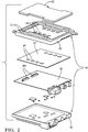
Figure 2 is an exploded view of one example radar unit. -
Figure 3 is a schematic of a heat transfer stack of the radar unit used for transferring heat from an integrated circuit (IC) chip to a radome. -
Figure 4A is a perspective view of one example heat transfer stack that includes a heat spreader, a heat sink and a spring. -
Figure 4B is a schematic partial cross-sectional view of the heat transfer stack shown inFigure 4A arranged in a radar unit housing. -
Figure 5 is a schematic partial cross-sectional view of another example heat transfer stack arranged in another radar unit housing. -
Figure 6 is a side view of the heat transfer stack shown inFigure 4B . -
Figure 7 is a partial perspective view of an example heat transfer bar. -
Figures 8A and 8B respectively are side elevation and top elevation views of the heat transfer bar shown inFigure 7 with a supported spring. -
Figure 9 is a side elevation view of multiple, discrete springs for use with a heat transfer bar similar to that shown inFigure 7 . -
Figure 10 is a perspective view of an electromagnetic interference (EMI) shield arranged about the IC chip and mounted on a printed circuit board (PCB). -
Figure 11 is a perspective view of an example spring imbedded within a radome. -
Figure 12 is a cross-sectional view of the spring engaging the EMI shield shown inFigure 10 and the IC chip. -
Figure 13 is an elevation view of a plating deposited onto the radome and configured to engage a spring. - The embodiments, examples and alternatives of the preceding paragraphs, the claims, or the following description and drawings, including any of their various aspects or respective individual features, may be taken independently or in any combination. Features described in connection with one embodiment are applicable to all embodiments, unless such features are incompatible. Like reference numbers and designations in the various drawings indicate like elements.
- An example
vehicle radar system 10 is schematically illustrated inFigure 1 . Thesystem 10 includes acontroller 12 in communication with a variety of components that provide driver assist features. In one example, aradar unit 14, such as an automotive long-range radar (e.g., 77 GHz) is in communication with a controller; however, it should be understood that other types of radar units (e.g., 24 GHz short range radar) may incorporate the disclosed heat transfer scheme. One or moreother sensors controller 12. - The various sensors cooperate to aid the driver in operating the vehicle, such as providing brake assist 16, steering
assist 18, andautomated cruise control 20. Various other assist orcontrol systems 22 may be provided in thevehicle 10 to provide improved vehicle safety. - An
example radar unit 14 is illustrated inFigure 2 . Theradar unit 14 includes amulti-piece housing 28 comprising at least first andsecond housing portions second PCBs housing 28. ThePCBs second connector portions - As radar units evolve and become more powerful and complex, a significant amount of heat is generated within the radar unit that must managed. In one example type of radar unit, multiple (e.g., eight) integrated circuit chips (IC chips 40), such as monolithic microwave integrated circuits (MMICs), are used to generate microwaves that sense surrounding objects in relation to the
vehicle 10. The wave-generating and receivingIC chips 40, such as the MMICs, are arranged on an outer face of thePCB 34. - The
housing 28 includes aradome 42 arranged over the IC chips 40. Theradome 42 is constructed of a plastic material, such as polybutylene terephthalate (PBT), which enables the waves from the IC chips 40 to easily pass through theradome 42. In the example shown inFigures 2 and5 , thefirst housing portion 30 includes an aperture that is sealed by theradome 42, such that theradome 42 and thefirst housing portion 30 may be constructed of different materials. In the example shown inFigure 4B , thefirst housing portion 30 may be constructed of the same plastic as theradome 42 such they are a seamless, unitary structure. Such a plastic radome is typically not a very good thermal conductor. - The MMICs generate a significant amount of heat during operation. A
heat transfer stack 44 is employed, as schematically illustrated inFigure 3 , to transfer heat from the IC chips 40 to theradome 42. One typical PBT material used for theradome 42 has a relatively low thermal conductivity, for example, approximately 270 W/m-K. Nonetheless, this low thermal conductively is much more thermally conductive than air (by approximately 10 times). While heat transfer across theradome 42 will not remove all of the MMIC-generated heat, taking advantage of this thermal feature can significantly improve overall sensor thermal performance, particularly if a heat transfer stack is used to provide conduction between theIC chip 40 and theradome 42, as shown inFigure 3 . As an example, a 108 mm2 area of aPBT radome 42 can transfer approximately 0.58 Watts with a 40°C temperature differential across theradome 42. - The problem of heat sinking the MMICs through the front face of the
radar unit 14, i.e., theradome 42, is solved by introducing aheat spreader 46 to spread and conduct the heat through theradome 42, as shown inFigure 3 . One ormore IC chips 40 mounted on the printedcircuit board 34 are in engagement with aheat spreader 46, which also firmly engages theradome 42. In this manner, theheat spreader 46, which may comprise one or more discrete components, conductively transfers heat from theIC chip 40 to theradome 42. - Referring to
Figures 4A-4B , an example heat transfer stack is illustrated. In one example, theradome 42 is provided by thefirst housing portion 30. Additional surface area features could be incorporated on the outer, front face of theradome 42 to increase overall heat transfer to the ambient air. For example, thefirst housing portion 30 is a molded plastic material, which may includemultiple fins 31 to assist in dissipation of heat from theradome 42. The first andsecond housing portions - In one embodiment, these single or multiple stamped metallic conductive heat spreaders incorporate contact springs, described below, that provide one or more points of thermal contact to the front face of each MMIC while maintaining multiple points of contact to the interior face of the
radome 42. These spring contacts allow for the heat spreading away from the heat generating face of the MMIC while transferring heat through theplastic radome 42. The springs also provide for vertical assembly tolerance to assure constant contact between the MMIC and theradome 42. - The
radome 42 includes aheat sink 48 embedded into an interior surface of theradome 42 facing the IC chips 40. Theheat sink 48 includes aslot 49 that receiveslegs 51 of aheat transfer bar 50. One or more thin,flexible springs 52 physically contact and engage the IC chips 40 and theheat transfer bar 50. Theheat sink 48, theheat transfer bar 50, and thespring 52 are a highly thermally conductive material such as a metal, for example, copper, magnesium or aluminum. - The
spring 52 may be secured to theheat transfer bar 50 to simplify final assembly of theradar unit 14. Attachments such as solder, braze, adhesive, rivets, fasteners, or other attaching mechanisms may be used to secure thespring 52 to theheat transfer bar 50. Theheat transfer bar 50 with its attachedsprings 52 may then be inserted in theslots 49 of theheat sink 48, which provides a unitary assembly with thefirst housing portion 30. Alternatively, thesprings 52 may be integrated into theheat transfer bar 50 as a single, unitary structure without any separate attachments. - In another example, as shown in
Figure 5 and13 , theheat transfer bar 58 may be adhered directly to the inner surface of theradome 142, for example, by plating theheat transfer bar 58 directly onto theradome 142 using a suitable metal deposition technique. The area of engagement of thesprings 452 with theheat transfer bar 58 is illustrated by dashed lines inFigure 13 . - As shown in
Figure 5 , theradome 142 may be provided by a plastic material, while thefirst housing portion 130 may be provided by another material, such as a different plastic material or metal for improved heat transfer. An interlockingprofile 56 may be provided between theradome 142 and thefirst housing portion 130, for example, by over-molding theradome 42 within the aperture provided by thefirst housing portion 130. - Referring to
Figure 6 , thespring 52 includes flexible first andsecond undulations first undulations 60 engage theheat transfer bar 50, and thesecond undulations 62 engage the IC chips 40. It should be understood that the multiple undulations may engage each chip, or a single undulation may be sufficient to provide the desired heat transfer. One example type of contact spring is described in United States Patent Number8,465,008 , which is incorporated herein by reference in its entirety. Additionally, a single spring may be used to engage multiple chips, if desired, as illustrated inFigure 6 . - To simplify the support of the spring with respect to the
radome 42, theheat transfer bar 150, as shown inFigure 7 , may includenotches 64 that receivetabs 66 of thespring 152, as illustrated inFigures 8A-8B .Discrete springs 252 may be provided, as illustrated inFigure 9 . - The stamped metallic springs may also provide electromagnetic interference (EMI) isolation between neighboring MMICs and can be electrically interfaced to a ground of the PCB. Protection against EMI may be provided for the IC chips 40, as schematically illustrated in
Figures 10-12 . Anelectromagnetic shield 68 is mounted to the printedcircuit board 134 and electrically connected to aground 70. Aspring 352 engaging theradome 242 is an electrical contact with theelectromagnetic shield 68 and in thermal engagement with thechip 40. Thespring 352 may include aclip 72 embedded within theradome 242 to eliminate the separate components of the heat sink and the heat transfer bar, if desired. - It should also be understood that although a particular component arrangement is disclosed in the illustrated embodiment, other arrangements will benefit herefrom. Although particular step sequences are shown, described, and claimed, it should be understood that steps may be performed in any order, separated or combined unless otherwise indicated and will still benefit from the present invention.
- Although the different examples have specific components shown in the illustrations, embodiments of this invention are not limited to those particular combinations. It is possible to use some of the components or features from one of the examples in combination with features or components from another one of the examples.
- Although an example embodiment has been disclosed, a worker of ordinary skill in this art would recognize that certain modifications would come within the scope of the claims. For that reason, the following claims should be studied to determine their true scope and content.
Claims (15)
- A radar unit (14) comprising:a printed circuit board (PCB) (34) supporting an integrated circuit (IC) chip (40);a radome (42) arranged over the IC chip (40); anda spring (52) engaging the IC chip (40) and the radome (42), the spring (52) configured to transfer thermal energy between the IC chip (40) and the radome (42).
- The radar unit (14) of claim 1, wherein the IC chip (40) is a monolithic microwave integrated circuit (MMIC).
- The radar unit (14) of claim 1 or 2, wherein the radome (42) is constructed from a plastic material, and the spring (52) is constructed from a corrugated metallic material having flexible undulations (60, 62).
- The radar unit (14) of any of the preceding claims, wherein the radome (42) includes a metallic heat transfer bar (50), the spring (52) engaging the heat transfer bar (50).
- The radar unit (14) of claim 4, wherein the heat transfer bar (50) is provided by a metallic plating (58) deposited onto the plastic material.
- The radar unit (14) of claim 4 or 5, wherein the radome (42) includes a slot (49) that receives the heat transfer bar (50).
- The radar unit (14) of claim 6, wherein the heat transfer bar (150) includes a notch (64), and the spring (52) has a tab (66) that is received in the slot (49) and within the notch (64).
- The radar unit (14) of any of the preceding claims, wherein an electromagnetic interference (EMI) shield (68) is mounted to the PCB (34) about the IC chip (40), and the spring (52) engages the EMI shield (68).
- The radar unit (14) of any of the preceding claims, comprising a plastic housing arranged about the PCB (34), and the radome (42) is provided by the plastic housing.
- The radar unit (14) of claim 9, wherein the housing (28) includes cooling fins (31).
- The radar unit (14) of any of the preceding claims, comprising a metallic housing arranged about the PCB (34), and the housing includes an aperture, and the radome (42) is overmolded within the aperture.
- The radar unit (14) of any of the preceding claims, wherein the PCB (34) includes a row of IC chips (40), and a common spring engages each of the IC chips (40) within the row.
- A radar unit (14) comprising:a radar generating unit (14) for emitting microwaves;a radome (42) arranged over the radar generating unit (14); anda heat transfer stack (44) for transferring thermal energy between the radar generating unit (14) and the radome (42), the heat transfer stack (44) engaging the radome (42) and the radar generating unit (14).
- The radar unit (14) of claim 13, wherein the radar generating unit (14) is a monolithic microwave integrated circuit (MMIC), the radome (242) is constructed from a plastic material, and the heat transfer stack (44) is a spring (52) constructed from a corrugated metallic material.
- The radar unit (14) of claim 13 or 14, comprising a shielding device (68) for minimizing electromagnetic interference with the radar generating unit (14), the heat transfer stack (44) engaging the shielding device (68).
Applications Claiming Priority (1)
| Application Number | Priority Date | Filing Date | Title |
|---|---|---|---|
| US16/399,059 US10965014B2 (en) | 2019-04-30 | 2019-04-30 | Radar unit with thermal transfer via radome |
Publications (2)
| Publication Number | Publication Date |
|---|---|
| EP3734322A1 true EP3734322A1 (en) | 2020-11-04 |
| EP3734322B1 EP3734322B1 (en) | 2026-05-06 |
Family
ID=70110104
Family Applications (1)
| Application Number | Title | Priority Date | Filing Date |
|---|---|---|---|
| EP20167124.5A Active EP3734322B1 (en) | 2019-04-30 | 2020-03-31 | Radar unit with thermal transfer via radome |
Country Status (3)
| Country | Link |
|---|---|
| US (1) | US10965014B2 (en) |
| EP (1) | EP3734322B1 (en) |
| CN (1) | CN111867344A (en) |
Cited By (4)
| Publication number | Priority date | Publication date | Assignee | Title |
|---|---|---|---|---|
| US11322833B2 (en) | 2019-06-03 | 2022-05-03 | Space Exploration Technologies Corp. | Antenna apparatus having fastener system |
| US12334630B2 (en) | 2021-11-09 | 2025-06-17 | Space Exploration Technologies Corp. | Radome assembly having nodeless cells |
| US12374772B2 (en) | 2021-11-09 | 2025-07-29 | Space Exploration Technologies Corp. | User terminal housing |
| EP4600687A1 (en) * | 2024-02-08 | 2025-08-13 | Aptiv Technologies AG | Radar device and method for manufacturing the same |
Families Citing this family (9)
| Publication number | Priority date | Publication date | Assignee | Title |
|---|---|---|---|---|
| DE102018105702A1 (en) * | 2018-03-13 | 2019-09-19 | HELLA GmbH & Co. KGaA | Radar device, in particular for a motor vehicle |
| US12137515B2 (en) * | 2021-02-01 | 2024-11-05 | Aptiv Technologies AG | Electromagnetic interference shielding and thermal management systems and methods for automotive radar applications |
| JP2023009863A (en) * | 2021-07-08 | 2023-01-20 | 株式会社光波 | sensor unit |
| US12055654B2 (en) * | 2021-08-20 | 2024-08-06 | Gm Cruise Holdings Llc | Scanning radar system with substrate integrated waveguides and heat dissipating structures |
| US20230170598A1 (en) * | 2021-08-24 | 2023-06-01 | Kymeta Corporation | Peripheral rf choke and z direction heat pipe |
| CN114924231A (en) * | 2022-04-18 | 2022-08-19 | 无锡威孚高科技集团股份有限公司 | 4D Imaging Millimeter Wave Radar |
| US20230408636A1 (en) * | 2022-06-16 | 2023-12-21 | Aptiv Technologies Limited | Metalized plastic housing enclosure heat sink |
| CN115234557B (en) * | 2022-09-21 | 2022-12-06 | 深圳市国天电子股份有限公司 | Vehicle-mounted millimeter wave radar component processing equipment and method |
| DE102024109808A1 (en) * | 2024-04-09 | 2025-10-09 | HELLA GmbH & Co. KGaA | Arrangement with a holder and a housing for an electronic assembly, in particular for a radar sensor, assembly with such an arrangement and method for producing such an arrangement |
Citations (4)
| Publication number | Priority date | Publication date | Assignee | Title |
|---|---|---|---|---|
| WO2010018934A2 (en) * | 2008-08-13 | 2010-02-18 | Electronics And Telecommunications Research Institute | System for controlling temperature of antenna module |
| EP2538106A2 (en) * | 2011-06-20 | 2012-12-26 | Delphi Technologies, Inc. | Complex wave spring |
| EP3070784A1 (en) * | 2015-03-18 | 2016-09-21 | Toyota Jidosha Kabushiki Kaisha | Vehicle radar apparatus |
| DE102016119274A1 (en) * | 2016-10-11 | 2018-04-12 | HELLA GmbH & Co. KGaA | Radar sensor with a cover |
Family Cites Families (16)
| Publication number | Priority date | Publication date | Assignee | Title |
|---|---|---|---|---|
| GB2301712B (en) | 1995-06-02 | 2000-02-23 | Dsc Communications | Integrated directional antenna |
| GB2362761A (en) * | 2000-05-24 | 2001-11-28 | Motorola Inc | PCB assembly and method therefor |
| US20060087816A1 (en) * | 2004-09-21 | 2006-04-27 | Ingo Ewes | Heat-transfer devices |
| US7292439B2 (en) * | 2005-01-19 | 2007-11-06 | Raytheon Company | Thermal management system and method for electronic assemblies |
| CN101452327A (en) * | 2007-12-06 | 2009-06-10 | 英业达股份有限公司 | Fixing device |
| US20130032324A1 (en) * | 2011-08-03 | 2013-02-07 | Aldridge Russell W | Thermal solution with spring-loaded interface |
| US9209523B2 (en) | 2012-02-24 | 2015-12-08 | Futurewei Technologies, Inc. | Apparatus and method for modular multi-sector active antenna system |
| CN103458658A (en) * | 2013-08-19 | 2013-12-18 | 徐州科亚机电有限公司 | Controller for electric vehicle |
| JP6309619B2 (en) * | 2013-10-01 | 2018-04-11 | オートリブ エー・エス・ピー・インク | Compact shield automotive radar module and method |
| US20160064807A1 (en) * | 2014-08-29 | 2016-03-03 | Laird Technologies, Inc. | Multiband Vehicular Antenna Assemblies |
| CN107210511B (en) | 2015-02-26 | 2019-12-17 | 华为技术有限公司 | Antenna frame structure |
| CN206743753U (en) * | 2017-04-28 | 2017-12-12 | 比亚迪股份有限公司 | Heat dissipation structure of electronic products and electronic products |
| CN107889431A (en) * | 2017-11-24 | 2018-04-06 | 华域汽车系统股份有限公司 | A kind of radiator structure of millimetre-wave radar |
| CN207639028U (en) * | 2017-12-25 | 2018-07-20 | 广州市骏创音响设备有限公司 | A kind of good power amplifier of heat dissipation |
| CN207835921U (en) * | 2018-02-10 | 2018-09-07 | 东莞科慧节能有限公司 | heat sink for circuit board |
| CN208210532U (en) * | 2018-04-11 | 2018-12-07 | 东莞市速传电子材料有限公司 | A heat-conducting wave-absorbing sheet |
-
2019
- 2019-04-30 US US16/399,059 patent/US10965014B2/en active Active
-
2020
- 2020-03-31 EP EP20167124.5A patent/EP3734322B1/en active Active
- 2020-04-29 CN CN202010354290.5A patent/CN111867344A/en active Pending
Patent Citations (5)
| Publication number | Priority date | Publication date | Assignee | Title |
|---|---|---|---|---|
| WO2010018934A2 (en) * | 2008-08-13 | 2010-02-18 | Electronics And Telecommunications Research Institute | System for controlling temperature of antenna module |
| EP2538106A2 (en) * | 2011-06-20 | 2012-12-26 | Delphi Technologies, Inc. | Complex wave spring |
| US8465008B2 (en) | 2011-06-20 | 2013-06-18 | Delphi Technologies, Inc. | Complex wave spring |
| EP3070784A1 (en) * | 2015-03-18 | 2016-09-21 | Toyota Jidosha Kabushiki Kaisha | Vehicle radar apparatus |
| DE102016119274A1 (en) * | 2016-10-11 | 2018-04-12 | HELLA GmbH & Co. KGaA | Radar sensor with a cover |
Cited By (12)
| Publication number | Priority date | Publication date | Assignee | Title |
|---|---|---|---|---|
| US11322833B2 (en) | 2019-06-03 | 2022-05-03 | Space Exploration Technologies Corp. | Antenna apparatus having fastener system |
| US11509048B2 (en) | 2019-06-03 | 2022-11-22 | Space Exploration Technologies Corp. | Antenna apparatus having antenna spacer |
| US11600915B2 (en) * | 2019-06-03 | 2023-03-07 | Space Exploration Technologies Corp. | Antenna apparatus having heat dissipation features |
| US11652286B2 (en) | 2019-06-03 | 2023-05-16 | Space Exploration Technology Corp. | Antenna apparatus having adhesive coupling |
| US11843168B2 (en) | 2019-06-03 | 2023-12-12 | Space Exploration Technologies Corp. | Antenna apparatus having antenna spacer |
| US12142826B2 (en) | 2019-06-03 | 2024-11-12 | Space Exploration Technologies Corp. | Antenna apparatus having heat dissipation features |
| US12237575B2 (en) | 2019-06-03 | 2025-02-25 | Space Explortion Technologies Corp. | Antenna apparatus having radome spacing |
| US12355148B2 (en) | 2019-06-03 | 2025-07-08 | Space Exploration Technologies Corp. | Antenna apparatus having chassis portion |
| US12334630B2 (en) | 2021-11-09 | 2025-06-17 | Space Exploration Technologies Corp. | Radome assembly having nodeless cells |
| US12374772B2 (en) | 2021-11-09 | 2025-07-29 | Space Exploration Technologies Corp. | User terminal housing |
| US12463333B2 (en) | 2021-11-09 | 2025-11-04 | Space Exploration Technologies Corp. | Radome assembly coupling with antenna assembly |
| EP4600687A1 (en) * | 2024-02-08 | 2025-08-13 | Aptiv Technologies AG | Radar device and method for manufacturing the same |
Also Published As
| Publication number | Publication date |
|---|---|
| US20200350670A1 (en) | 2020-11-05 |
| EP3734322B1 (en) | 2026-05-06 |
| CN111867344A (en) | 2020-10-30 |
| US10965014B2 (en) | 2021-03-30 |
Similar Documents
| Publication | Publication Date | Title |
|---|---|---|
| EP3734322B1 (en) | Radar unit with thermal transfer via radome | |
| KR100327714B1 (en) | Control device, especially for a motor vehicle | |
| EP3327767B1 (en) | Mount structure, method of manufacturing mount structure, and wireless device | |
| EP1943674B1 (en) | Method and apparatus for grounding a heat sink in thermal contact with an electronic component using a grounding spring having multiple-jointed fingers | |
| EP1037517A2 (en) | Electronic component heat sink assembly | |
| US12313767B2 (en) | Method for manufacturing a radar sensor | |
| US20220349220A1 (en) | Vehicle outside door handle with radar module and thermal management | |
| JPH0583144A (en) | Module transmitter | |
| US6430043B1 (en) | Heat sink grounding unit | |
| EP3914055B1 (en) | Circuit connection module | |
| EP3065167B1 (en) | High-frequency module and microwave transceiver | |
| US8508943B2 (en) | Cooling active circuits | |
| US6587346B1 (en) | Combination electrical power distribution and heat dissipating device | |
| US20230025442A1 (en) | Assortment of radar sensors | |
| US12137515B2 (en) | Electromagnetic interference shielding and thermal management systems and methods for automotive radar applications | |
| JP2021118212A (en) | Electronic control device | |
| US12446146B2 (en) | Radar system | |
| US12010790B2 (en) | High-frequency circuit including a circuit board and a waveguide structure | |
| JP2002176279A (en) | Radiation structure of electronic unit box and method of manufacturing electronic unit | |
| AU2020297899B2 (en) | Modular electronically scanned array (ESA) | |
| US20250280490A1 (en) | Control device for a vehicle | |
| US20230328875A1 (en) | High-frequency component, electric circuit arrangement and radar system | |
| EP4600687A1 (en) | Radar device and method for manufacturing the same | |
| KR100843439B1 (en) | Elastic radiator and electronic device having same | |
| WO2000038490A1 (en) | A method and a device for shielding electronic components |
Legal Events
| Date | Code | Title | Description |
|---|---|---|---|
| PUAI | Public reference made under article 153(3) epc to a published international application that has entered the european phase |
Free format text: ORIGINAL CODE: 0009012 |
|
| STAA | Information on the status of an ep patent application or granted ep patent |
Free format text: STATUS: THE APPLICATION HAS BEEN PUBLISHED |
|
| AK | Designated contracting states |
Kind code of ref document: A1 Designated state(s): AL AT BE BG CH CY CZ DE DK EE ES FI FR GB GR HR HU IE IS IT LI LT LU LV MC MK MT NL NO PL PT RO RS SE SI SK SM TR |
|
| AX | Request for extension of the european patent |
Extension state: BA ME |
|
| STAA | Information on the status of an ep patent application or granted ep patent |
Free format text: STATUS: REQUEST FOR EXAMINATION WAS MADE |
|
| 17P | Request for examination filed |
Effective date: 20210504 |
|
| RBV | Designated contracting states (corrected) |
Designated state(s): AL AT BE BG CH CY CZ DE DK EE ES FI FR GB GR HR HU IE IS IT LI LT LU LV MC MK MT NL NO PL PT RO RS SE SI SK SM TR |
|
| STAA | Information on the status of an ep patent application or granted ep patent |
Free format text: STATUS: EXAMINATION IS IN PROGRESS |
|
| 17Q | First examination report despatched |
Effective date: 20220527 |
|
| RAP3 | Party data changed (applicant data changed or rights of an application transferred) |
Owner name: APTIV TECHNOLOGIES LIMITED |
|
| RAP1 | Party data changed (applicant data changed or rights of an application transferred) |
Owner name: APTIV TECHNOLOGIES AG |
|
| RAP3 | Party data changed (applicant data changed or rights of an application transferred) |
Owner name: APTIV TECHNOLOGIES AG |
|
| REG | Reference to a national code |
Ref country code: DE Ref legal event code: R079 Ipc: G01S0007020000 Ref country code: DE Ref legal event code: R079 Ref document number: 602020071469 Country of ref document: DE Free format text: PREVIOUS MAIN CLASS: G01S0007030000 Ipc: G01S0007020000 |
|
| GRAP | Despatch of communication of intention to grant a patent |
Free format text: ORIGINAL CODE: EPIDOSNIGR1 |
|
| STAA | Information on the status of an ep patent application or granted ep patent |
Free format text: STATUS: GRANT OF PATENT IS INTENDED |
|
| RIC1 | Information provided on ipc code assigned before grant |
Ipc: G01S 7/02 20060101AFI20251016BHEP Ipc: G01S 7/03 20060101ALI20251016BHEP Ipc: G01S 13/931 20200101ALI20251016BHEP |
|
| INTG | Intention to grant announced |
Effective date: 20251028 |
|
| GRAS | Grant fee paid |
Free format text: ORIGINAL CODE: EPIDOSNIGR3 |
|
| P01 | Opt-out of the competence of the unified patent court (upc) registered |
Free format text: CASE NUMBER: UPC_APP_0003640_3734322/2026 Effective date: 20260202 |
|
| GRAA | (expected) grant |
Free format text: ORIGINAL CODE: 0009210 |
|
| STAA | Information on the status of an ep patent application or granted ep patent |
Free format text: STATUS: THE PATENT HAS BEEN GRANTED |
|
| AK | Designated contracting states |
Kind code of ref document: B1 Designated state(s): AL AT BE BG CH CY CZ DE DK EE ES FI FR GB GR HR HU IE IS IT LI LT LU LV MC MK MT NL NO PL PT RO RS SE SI SK SM TR |
|
| REG | Reference to a national code |
Ref country code: CH Ref legal event code: F10 Free format text: ST27 STATUS EVENT CODE: U-0-0-F10-F00 (AS PROVIDED BY THE NATIONAL OFFICE) Effective date: 20260506 Ref country code: GB Ref legal event code: FG4D |