EP3734214A1 - Cooling device - Google Patents
Cooling device Download PDFInfo
- Publication number
- EP3734214A1 EP3734214A1 EP18896705.3A EP18896705A EP3734214A1 EP 3734214 A1 EP3734214 A1 EP 3734214A1 EP 18896705 A EP18896705 A EP 18896705A EP 3734214 A1 EP3734214 A1 EP 3734214A1
- Authority
- EP
- European Patent Office
- Prior art keywords
- pair
- tubular portion
- base block
- wall parts
- heat pipe
- Prior art date
- Legal status (The legal status is an assumption and is not a legal conclusion. Google has not performed a legal analysis and makes no representation as to the accuracy of the status listed.)
- Granted
Links
Images


Classifications
-
- F—MECHANICAL ENGINEERING; LIGHTING; HEATING; WEAPONS; BLASTING
- F28—HEAT EXCHANGE IN GENERAL
- F28D—HEAT-EXCHANGE APPARATUS, NOT PROVIDED FOR IN ANOTHER SUBCLASS, IN WHICH THE HEAT-EXCHANGE MEDIA DO NOT COME INTO DIRECT CONTACT
- F28D15/00—Heat-exchange apparatus with the intermediate heat-transfer medium in closed tubes passing into or through the conduit walls ; Heat-exchange apparatus employing intermediate heat-transfer medium or bodies
- F28D15/02—Heat-exchange apparatus with the intermediate heat-transfer medium in closed tubes passing into or through the conduit walls ; Heat-exchange apparatus employing intermediate heat-transfer medium or bodies in which the medium condenses and evaporates, e.g. heat pipes
- F28D15/0275—Arrangements for coupling heat-pipes together or with other structures, e.g. with base blocks; Heat pipe cores
-
- B—PERFORMING OPERATIONS; TRANSPORTING
- B21—MECHANICAL METAL-WORKING WITHOUT ESSENTIALLY REMOVING MATERIAL; PUNCHING METAL
- B21D—WORKING OR PROCESSING OF SHEET METAL OR METAL TUBES, RODS OR PROFILES WITHOUT ESSENTIALLY REMOVING MATERIAL; PUNCHING METAL
- B21D39/00—Application of procedures in order to connect objects or parts, e.g. coating with sheet metal otherwise than by plating; Tube expanders
- B21D39/06—Application of procedures in order to connect objects or parts, e.g. coating with sheet metal otherwise than by plating; Tube expanders of tubes in openings, e.g. rolling-in
-
- B—PERFORMING OPERATIONS; TRANSPORTING
- B21—MECHANICAL METAL-WORKING WITHOUT ESSENTIALLY REMOVING MATERIAL; PUNCHING METAL
- B21D—WORKING OR PROCESSING OF SHEET METAL OR METAL TUBES, RODS OR PROFILES WITHOUT ESSENTIALLY REMOVING MATERIAL; PUNCHING METAL
- B21D53/00—Making other particular articles
- B21D53/02—Making other particular articles heat exchangers or parts thereof, e.g. radiators, condensers fins, headers
- B21D53/08—Making other particular articles heat exchangers or parts thereof, e.g. radiators, condensers fins, headers of both metal tubes and sheet metal
-
- H—ELECTRICITY
- H05—ELECTRIC TECHNIQUES NOT OTHERWISE PROVIDED FOR
- H05K—PRINTED CIRCUITS; CASINGS OR CONSTRUCTIONAL DETAILS OF ELECTRIC APPARATUS; MANUFACTURE OF ASSEMBLAGES OF ELECTRICAL COMPONENTS
- H05K7/00—Constructional details common to different types of electric apparatus
- H05K7/20—Modifications to facilitate cooling, ventilating, or heating
- H05K7/2029—Modifications to facilitate cooling, ventilating, or heating using a liquid coolant with phase change in electronic enclosures
- H05K7/20336—Heat pipes, e.g. wicks or capillary pumps
-
- H—ELECTRICITY
- H05—ELECTRIC TECHNIQUES NOT OTHERWISE PROVIDED FOR
- H05K—PRINTED CIRCUITS; CASINGS OR CONSTRUCTIONAL DETAILS OF ELECTRIC APPARATUS; MANUFACTURE OF ASSEMBLAGES OF ELECTRICAL COMPONENTS
- H05K7/00—Constructional details common to different types of electric apparatus
- H05K7/20—Modifications to facilitate cooling, ventilating, or heating
- H05K7/2089—Modifications to facilitate cooling, ventilating, or heating for power electronics, e.g. for inverters for controlling motor
- H05K7/20936—Liquid coolant with phase change
-
- H—ELECTRICITY
- H10—SEMICONDUCTOR DEVICES; ELECTRIC SOLID-STATE DEVICES NOT OTHERWISE PROVIDED FOR
- H10W—GENERIC PACKAGES, INTERCONNECTIONS, CONNECTORS OR OTHER CONSTRUCTIONAL DETAILS OF DEVICES COVERED BY CLASS H10
- H10W40/00—Arrangements for thermal protection or thermal control
- H10W40/01—Manufacture or treatment
- H10W40/03—Manufacture or treatment of arrangements for cooling
- H10W40/037—Assembling together parts thereof
-
- H—ELECTRICITY
- H10—SEMICONDUCTOR DEVICES; ELECTRIC SOLID-STATE DEVICES NOT OTHERWISE PROVIDED FOR
- H10W—GENERIC PACKAGES, INTERCONNECTIONS, CONNECTORS OR OTHER CONSTRUCTIONAL DETAILS OF DEVICES COVERED BY CLASS H10
- H10W40/00—Arrangements for thermal protection or thermal control
- H10W40/70—Fillings or auxiliary members in containers or in encapsulations for thermal protection or control
- H10W40/73—Fillings or auxiliary members in containers or in encapsulations for thermal protection or control for cooling by change of state
-
- B—PERFORMING OPERATIONS; TRANSPORTING
- B23—MACHINE TOOLS; METAL-WORKING NOT OTHERWISE PROVIDED FOR
- B23P—METAL-WORKING NOT OTHERWISE PROVIDED FOR; COMBINED OPERATIONS; UNIVERSAL MACHINE TOOLS
- B23P15/00—Making specific metal objects by operations not covered by a single other subclass or a group in this subclass
- B23P15/26—Making specific metal objects by operations not covered by a single other subclass or a group in this subclass heat exchangers or the like
-
- F—MECHANICAL ENGINEERING; LIGHTING; HEATING; WEAPONS; BLASTING
- F28—HEAT EXCHANGE IN GENERAL
- F28D—HEAT-EXCHANGE APPARATUS, NOT PROVIDED FOR IN ANOTHER SUBCLASS, IN WHICH THE HEAT-EXCHANGE MEDIA DO NOT COME INTO DIRECT CONTACT
- F28D21/00—Heat-exchange apparatus not covered by any of the groups F28D1/00 - F28D20/00
- F28D2021/0019—Other heat exchangers for particular applications; Heat exchange systems not otherwise provided for
- F28D2021/0028—Other heat exchangers for particular applications; Heat exchange systems not otherwise provided for for cooling heat generating elements, e.g. for cooling electronic components or electric devices
-
- F—MECHANICAL ENGINEERING; LIGHTING; HEATING; WEAPONS; BLASTING
- F28—HEAT EXCHANGE IN GENERAL
- F28D—HEAT-EXCHANGE APPARATUS, NOT PROVIDED FOR IN ANOTHER SUBCLASS, IN WHICH THE HEAT-EXCHANGE MEDIA DO NOT COME INTO DIRECT CONTACT
- F28D21/00—Heat-exchange apparatus not covered by any of the groups F28D1/00 - F28D20/00
- F28D2021/0019—Other heat exchangers for particular applications; Heat exchange systems not otherwise provided for
- F28D2021/008—Other heat exchangers for particular applications; Heat exchange systems not otherwise provided for for vehicles
-
- F—MECHANICAL ENGINEERING; LIGHTING; HEATING; WEAPONS; BLASTING
- F28—HEAT EXCHANGE IN GENERAL
- F28F—DETAILS OF HEAT-EXCHANGE AND HEAT-TRANSFER APPARATUS, OF GENERAL APPLICATION
- F28F1/00—Tubular elements; Assemblies of tubular elements
- F28F1/10—Tubular elements and assemblies thereof with means for increasing heat-transfer area, e.g. with fins, with projections, with recesses
- F28F1/12—Tubular elements and assemblies thereof with means for increasing heat-transfer area, e.g. with fins, with projections, with recesses the means being only outside the tubular element
- F28F1/24—Tubular elements and assemblies thereof with means for increasing heat-transfer area, e.g. with fins, with projections, with recesses the means being only outside the tubular element and extending transversely
- F28F1/32—Tubular elements and assemblies thereof with means for increasing heat-transfer area, e.g. with fins, with projections, with recesses the means being only outside the tubular element and extending transversely the means having portions engaging further tubular elements
-
- F—MECHANICAL ENGINEERING; LIGHTING; HEATING; WEAPONS; BLASTING
- F28—HEAT EXCHANGE IN GENERAL
- F28F—DETAILS OF HEAT-EXCHANGE AND HEAT-TRANSFER APPARATUS, OF GENERAL APPLICATION
- F28F2265/00—Safety or protection arrangements; Arrangements for preventing malfunction
- F28F2265/30—Safety or protection arrangements; Arrangements for preventing malfunction for preventing vibrations
-
- F—MECHANICAL ENGINEERING; LIGHTING; HEATING; WEAPONS; BLASTING
- F28—HEAT EXCHANGE IN GENERAL
- F28F—DETAILS OF HEAT-EXCHANGE AND HEAT-TRANSFER APPARATUS, OF GENERAL APPLICATION
- F28F2275/00—Fastening; Joining
- F28F2275/12—Fastening; Joining by methods involving deformation of the elements
- F28F2275/122—Fastening; Joining by methods involving deformation of the elements by crimping, caulking or clinching
Definitions
- the present invention relates to a cooling device that cools electrical and electronic components and other components, and particularly relates to a cooling device that cools electrical and electronic components installed in a mobile unit such as a railway vehicle.
- a cooling device which is used to cool a control device or other devices using a semiconductor element, has been conventionally known as cooling a heating element by using latent heat generated when refrigerant boils.
- a cooler has been proposed in which a plurality of tanks with a circular tubular shape are embedded in a base block that receives heat of a heating element such as a semiconductor element.
- a plurality of thin pipes are provided in a standing manner from the side of the exposed portion of the tank, and a plurality of fins are attached to the pipes, so that the cooler is capable of cooling heat of the heating element by using outside air (Patent Literature 1).
- the cooler with the pipes installed perpendicularly to the side of the base block is mounted on a vehicle, and when the vehicle runs on an incline, this may lead to a state where the space in the tank is partially filled with refrigerant in liquid form in the axial direction of the circular tube of the tank and then the liquid refrigerant may reach the pipes, or there is no refrigerant in liquid form at the bottom of the tank.
- the cooler includes a pipe formed of a base end portion having a connection end connected to a tank embedded on one side of a base block, and a heat radiating portion bent from the base end portion and having a closed end on the tip end side.
- the base end portion is inclined upward from the connection end at a predetermined first inclination angle relative to the horizontal direction.
- the heat radiating portion is provided at a second inclination angle equal to or greater than zero degrees and smaller than the first inclination angle of the base end portion relative to the horizontal direction.
- the liquid level of refrigerant is set at a position lower than the heat radiating portion (Patent Literature 2).
- the base block and each tank are joined integrally by soldering. Since lead solder is used in the joined portion between the base block and multiple tanks, this increases the environmental impacts.
- the lead-free solder has lower wettability compared to the lead solder and thus the joining force can become unstable. For this reason, there are concerns about the contact thermal conductance in a joined portion between the base block and a heat pipe, and about the resistance to vibration in the joined portion when the cooler is used in a mobile unit such as a vehicle.
- a crimping method which does not use joining materials such as solder.
- a base block made of metal is provided with grooves or holes in which a plurality of heat pipes are held, and is also provided with protruding portions intended for crimping. With the heat pipes accommodated in the grooves or holes, the protruding portions are crimped to fix the heat pipes to the base block (Patent Literature 3).
- a cooling device of the present invention includes: a base block including a back-side portion thermally connectable to a heating element; a heat pipe group formed of a plurality of heat pipes, each of which includes a first tubular portion and a second tubular portion, the first tubular portion being fixed to a front-side portion of the base block and being disposed along a planar direction of the base block, the second tubular portion being connected to the first tubular portion and being provided in a standing manner from the base block; and a fin group formed of a plurality of fins fixed to the heat pipe group, the fins being parallel to each other in a standing direction of the heat pipe group, characterized in that a plurality of the first tubular portions are fixed to one another through the base block, while a plurality of the second tubular portions are fixed to one another through the fin group, the base block includes a recessed part extending in a longitudinal direction and a width direction, and having the first tubular portion accommodated therein, and a pair of wall parts
- the pair of wall parts is a pair of elongated protruding portions protruding along an outer peripheral surface of the first tubular portion, and extending along a longitudinal direction of the first tubular portion, and each of the pair of elongated protruding portions includes a press-contact surface that press-contacts an outer peripheral surface of the first tubular portion.
- the pair of wall parts has an equal or nearly equal length in a protruding direction, and a gap portion with a groove-like shape is formed between tip end portions of the pair of wall parts.
- the cooling device may further include a fin member located between the base block and the fin group, wherein the fin member may include a plate-like base portion crimped and fixed between the first tubular portion and the pair of wall parts, and a fin portion connected to the plate-like base portion and provided in a standing manner through the gap portion formed between the tip end portions of the pair of wall parts.
- the base block may be located along a vertical direction.
- the first tubular portion of the heat pipe may be provided along a horizontal direction.
- the second tubular portion of the heat pipe may be inclined upward toward a tip end relative to a thickness direction of the base block.
- the pair of wall parts may protrude at an angle equal to, or nearly equal to, a standing angle of the second tubular portion relative to the base block.
- a manufacturing method of a cooling device of the present invention is characterized by including: a base-block forming step of forming a plurality of recessed parts, each of which extends in a longitudinal direction and a width direction, on a front-side portion of a base block, and further forming a pair of wall parts protruding linearly from opposite sides of each of the recessed parts in the width direction, while being inclined relative to a thickness direction of the base block; a crimping step of preparing a plurality of heat pipes, each of which includes a first tubular portion and a second tubular portion connected to the first tubular portion, and crimping the pair of wall parts in a state where the first tubular portion of the heat pipe is accommodated in the recessed part of the base block, and the second tubular portion of the heat pipe is provided in a standing manner from the base block; and a fin-group forming step of forming a fin group by fixing a plurality of fins to a heat pipe group formed of the
- the pair of wall parts having an equal or nearly equal length in an extending direction is formed, and in the crimping step, the pair of wall parts is pressed by a pressing force in a vertical direction in a state where the base block is inclined such that a pair of tip end portions of the pair of wall parts is maintained at a same height.
- a pressing force in the vertical direction may be applied to the pair of wall parts.
- a jig including a groove portion with an inverted U-shape may be used to press the groove portion against the pair of wall parts to press the pair of wall parts together.
- the reliability of joining between the base block and the heat pipe can be improved, while the environmental impacts are reduced, and high contact thermal conductance and high resistance to vibration can both be achieved.
- FIG. 1 is a schematic cross-sectional view showing the configuration of a cooling device according to an embodiment of the present invention.
- a railway vehicle is described as an example of a mobile unit having the cooling device installed therein.
- the configuration of the cooling device and the installation position of the cooling device shown in FIG. 1 are merely an example.
- the cooling device of the present invention and the installation position of this cooling device are not limited to those shown in FIG. 1 .
- a casing 200 in a sealed state is attached to an underfloor surface 101 of a vehicle 100 through an attachment 102.
- One side wall 201 of the casing 200 is formed with an opening 202.
- An opening-closing cover 203 that opens or closes the opening 202 is attached to the side wall 201 through a hinge 204 at the upper portion of the side wall 201.
- the opening-closing cover 203 is configured to be locked by a locking means (not shown) when the opening-closing cover 203 closes the opening 202.
- Another side wall 205 of the casing 200 is formed with a window hole 206.
- the window hole 206 is closed by a base block 10 attached to the side wall 205 on the outside of the side wall 205.
- the casing 200 is thereby held in a sealed state.
- a plurality of electrical components 300 such as a heating element that is, for example, a semiconductor module, are attached to a part of the base block 10, which faces the interior of the casing 200.
- other components 301, 302, and 303 that are respectively, for example, a snubber resistor, a snubber capacitor, and a gate amplifier are installed as other heating elements.
- a tubular cover 207 is attached such that the cover 207 extends along the airflow generated by running of the vehicle 100.
- a cooling device 1 is accommodated inside the cover 207.
- Support plates 208a and 208b that support and strengthen a heat pipe group 20 are also attached to the inside of the cover 207.
- the support plate 208a supports the heat pipe group 20 from below.
- one end portion of the support plate 208a is fixed to a bottom wall 209 of the cover 207, while the other end portion of the support plate 208a is fixed to a part of the heat pipe group 20.
- the support plate 208b supports the heat pipe group 20 from above.
- one end portion of the support plate 208b is fixed to a top wall 210 of the cover 207, while the other end portion of the support plate 208b is fixed to a part of the heat pipe group 20.
- the support plates 208a and 208b are thermally connected to the heat pipe group 20, and also serve as a heat radiating plate.
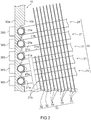
- FIG. 2 is a partial cross-sectional view showing the detailed configuration of the cooling device 1 in FIG. 1 .
- the cooling device 1 includes the base block 10 including a back-side portion 10a thermally connected to the electrical components 300 that are heating elements, the heat pipe group 20 formed of a plurality of heat pipes 21, each of which includes a first tubular portion 21a and a second tubular portion 21b, the first tubular portion 21a being fixed to a front-side portion 10b of the base block 10 and being disposed along the planar direction of the base block 10, the second tubular portion 21b being connected to the first tubular portion 21a and being provided in a standing manner from the base block 10, and a fin group 30 formed of a plurality of fins 31, 31, ... fixed to the heat pipe group 20, the fins 31, 31, ... being parallel to each other in the standing direction of the heat pipe group 20.
- the base block 10 is attached to the casing 200 along the side wall 205 in such a manner that the back-side portion 10a faces toward the casing 200, while the front-side portion 10b faces toward the cover 207 ( FIG. 1 ).
- the base block 10 is located along the vertical direction.
- the base block 10 is made of metal material such as aluminum or aluminum alloy, or copper or copper alloy.
- a plurality of heat pipes 21, 21, ... forming the heat pipe group 20 are provided next to and spaced apart from each other in an up-down direction, for example, in the vertical direction.
- Each of the heat pipes 21 is formed of a tubular member having, for example, a U-shape (see FIG. 6 ).
- the first tubular portion 21a has, for example, a circular tubular shape, and is filled with an amount of operating fluid equivalent to between 30% and 40% of the overall volume.
- the second tubular portion 21b has, for example, a circular tubular shape that is the same as the shape of the first tubular portion 21a.
- the first tubular portion 21a and the second tubular portion 21b may have a circular shape, an oval shape, or other shape in cross-section in the width direction.
- the first tubular portion 21a has a function of a heated portion to be heated by heat from the base block 10.
- the second tubular portion 21b has a function of a heat radiating portion that radiates heat from the first tubular portion 21a.
- the shape of the heat pipe 21 is not limited, but may be an L-shape or a looped shape, for example.
- the first tubular portion 21a and the second tubular portion 21b may be formed in one piece by bending a long pipe or other methods, or may be connected together by joining such as welding.
- the fins 31, 31, ... forming the fin group 30 are provided next to and spaced apart from each other in the standing direction of the second tubular portion 21b such that, for example, the main surfaces of the fins 31, 31, ... are parallel to each other.
- the fin 31 includes one or a plurality of holes corresponding to the positions of the heat pipes 21.
- the fin 31 is fixed to the heat pipes 21 by, for example, press fitting.
- the fin 31 has a function of the heat radiating portion that radiates heat from the second tubular portion 21b. That is, the fin 31 constitutes the heat radiating portion in cooperation with the second tubular portion 21b. As long as the fin 31 is configured to implement the function described above, the shape of the fin 31 is not limited.
- the fin 31 is connected with all the heat pipes 21, 21, ... in the direction of the heat pipe group 20 in which the heat pipes 21, 21, ... are provided next to each other.
- a fin 32 may also be provided, which is connected with some of the heat pipes 21, 21, ... in the direction of the heat pipe group 20 in which the heat pipes 21, 21, ... are provided next to each other.
- a plurality of first tubular portions 21a, 21a, ... are fixed to one another through the base block 10, while a plurality of second tubular portions 21b, 21b, ... are fixed to one another through the fin group 30.
- the fin group 30, formed of the fins 31, 31, ... connected with the heat pipes 21, 21, ... is regarded as a rigid body with a thickness whose value is obtained by multiplying the fin thickness by the number of fins. Therefore, even when vibration is applied to a heat sink formed of the heat pipe group 20 and the fin group 30, the respective distances between the heat pipes 21, 21, ... are still maintained by the fin group 30. This results in a structure in which a moment of force is minimally generated in each fixed portion between the base block 10 and each of the heat pipes 21 provided in a standing manner from the base block 10.
- the base block 10 is located along the vertical direction
- the first tubular portion 21a of the heat pipe 21 is provided along the horizontal direction
- the second tubular portion 21b of the heat pipe 21 is inclined upward toward the tip end of the second tubular portion 21b relative to the thickness direction of the base block 10 ( FIG. 1 ).
- the first tubular portion 21a with the longitudinal direction (axial direction) of the first tubular portion 21a extending along the traveling direction of the vehicle 100.
- the fin 31 along the traveling direction of the vehicle 100. This can improve the cooling efficiency.
- heat from the electrical components 300 and heat in the casing 200 generated from the other components 301, 302, and 303 and the like are transmitted through the base block 10 to the first tubular portion 21a of the heat pipe 21, then transferred to the second tubular portion 21b by a change in phase of the operating fluid in the interior of the first tubular portion 21a, and radiated to the exterior of the second tubular portion 21b through the fin 31.
- FIG. 3A is a cross-sectional view showing the detailed configuration of the base block 10 after the heat pipe group 20 has been fixed to the base block 10.
- FIG. 3B is a partially enlarged perspective view of the fixed portion in FIG. 3A.
- FIG. 3C is a cross-sectional view showing the configuration of the base block 10 before the heat pipe group 20 is fixed to the base block 10.
- the base block 10 includes a recessed part 11 extending in the longitudinal direction and the width direction and having the first tubular portion 21a accommodated therein, and a pair of wall parts 12a and 12a protruding from the opposite sides of the recessed part 11 in the width direction along the outer peripheral surface of the first tubular portion 21a.
- the heat pipe 21 is crimped and fixed to the recessed part 11 and the pair of wall parts 12a and 12a.
- the recessed part 11 is provided along the planar direction of the base block 10 such that, for example, the longitudinal direction of the recessed part 11 extends horizontally, while the width direction of the recessed part 11 extends vertically. It is preferable to provide the recessed part 11 with the longitudinal direction of the recessed part 11 extending along the traveling direction of the vehicle 100 (see FIG. 1 ).
- the pair of wall parts 12a and 12a is also provided along the planar direction of the base block 10 in the same manner as the recessed part 11. It is preferable that the wall part 12a extends along, for example, the extending direction of the recessed part 11, and extends parallel to the extending direction of the recessed part 11.
- the pair of wall parts 12a and 12a protrudes upward relative to the recessed part 11 in cross-section in the width direction, and is bent toward the center of the recessed part 11 in the width direction such that the wall parts 12a and 12a are brought closer to each other.
- each base portion of the pair of wall parts 12a and 12a may be formed at, for example, an angle equal to, or nearly equal to, the standing angle of the second tubular portion 21b relative to the base block 10.
- the pair of wall parts 12a and 12a may be formed at an inclination angle equal to, or nearly equal to, the inclination angle of the second tubular portion 21b inclined upward toward the tip end.
- the pair of wall parts 12a and 12a is a pair of elongated protruding portions protruding along an outer peripheral surface 21c of the first tubular portion 21a, and extending along the longitudinal direction (the X-direction in the drawing) of the first tubular portion 21a ( FIG. 3B ).
- each of the pair of elongated protruding portions includes a press-contact surface 12c that press-contacts the outer peripheral surface 21c of the first tubular portion 21a.
- the pair of elongated protruding portions includes a pair of press-contact surfaces 12c and 12c, so that the contact area between the first tubular portion 21a and the pair of elongated protruding portions is increased and accordingly a friction force is increased.
- the pair of wall parts 12a and 12a has an equal or nearly equal length in the protruding direction. Assuming that the pair of wall parts 12a and 12a has an equal or nearly equal length in the protruding direction, an equal or nearly equal pressing force can be simultaneously applied to both of the pair of wall parts 12a and 12a in a crimping step to be described later.
- a gap portion 13 with a groove-like shape may be formed between a pair of tip end portions 12d and 12d of the pair of wall parts 12a and 12a to prevent the pair of wall parts 12a and 12a from interfering with each other in the crimping step to be described later. It is preferable that the gap portion 13 with a groove-like shape has a minute width from the viewpoint of the contact area described above.
- the pair of wall parts 12a and 12a protrudes while being inclined relative to the thickness direction of the base block 10, that is, relative to a direction perpendicular to the front-side portion 10b as shown in FIG. 3C .
- the inclination angle of the pair of wall parts 12a and 12a is not limited to a particular angle, but is 10 degrees with respect to the thickness direction of the base block 10, for example (80 degrees with respect to the planar direction of the base block 10).
- the base block 10 is provided with a plurality of pairs of wall parts 12a and 12a corresponding to a plurality of recessed parts 11. It is preferable that the pairs of wall parts 12a and 12a are inclined at an equal inclination angle.
- the pair of wall parts 12a and 12a may be formed at, for example, an angle equal to, or nearly equal to, the standing angle of the second tubular portion 21b relative to the base block 10.
- the pair of wall parts 12a and 12a may be formed at an inclination angle equal to, or nearly equal to, the inclination angle of the second tubular portion 21b inclined upward toward the tip end.
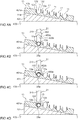
- FIG. 4 a manufacturing method of the cooling device 1 in FIG. 1 is described with reference to FIGs. 4A to 4D .
- the manufacturing method of the cooling device shown in FIGs. 4 is merely an example.
- the manufacturing method of a cooling device of the present invention is not limited to that shown in FIGs. 4 .
- a plurality of the recessed parts 11, each of which extends in the longitudinal direction and the width direction, are formed on the front-side portion 10b of the base block 10. Further, the pair of wall parts 12a and 12a is formed. The pair of wall parts 12a and 12a protrudes linearly from the opposite sides of each recessed part in the width direction, while being inclined relative to the thickness direction of the base block 10 (base-block forming step). At this time, it is preferable to form the pair of wall parts 12a and 12a with an equal length in the extending direction. The base block 10 is thereby obtained as shown in FIG. 3C .
- a press-fitting base 401 including an inclined portion 401a is mounted on a work table 400, and the base block 10 having been manufactured is placed on the inclined portion 401a and then fixed by using a jig (not shown) ( FIG. 4A ).
- the inclination angle of the inclined portion 401a such that the pair of wall parts 12a and 12a protrudes in the vertical direction.
- the inclination angle of the inclined portion 401a is set to 10 degrees with respect to the horizontal direction.
- the base block 10 In a case where the pair of wall parts 12a and 12a with an equal length in the extending direction is formed, it is preferable to incline the base block 10 such that the pair of tip end portions 12d and 12d of the pair of wall parts 12a and 12a is maintained at the same height.
- a plurality of the heat pipes 21 are prepared, each of which includes the first tubular portion 21a and the second tubular portion 21b connected to this tubular portion 21a, to accommodate the first tubular portion 21a of the heat pipe 21 in the recessed part 11 of the base block 10 ( FIG. 4B ).
- the second tubular portion 21b of each heat pipe 21 is provided in a standing manner from the base block 10 in the vertical direction. It is preferable to hold the heat pipe 21 such that the second tubular portion 21b is provided in a standing manner in a direction parallel to the pair of wall parts 12a and 12a.
- the pair of wall parts 12a and 12a is crimped in a state where the first tubular portion 21a of the heat pipe 21 is accommodated in the recessed part 11 of the base block 10, and where the second tubular portion 21b of the heat pipe 21 is provided in a standing manner from the base block 10 (crimping step) ( FIG. 4C ).
- a jig 402 is used, the jig 402 including a groove portion 402b having an inverted U-shape on a bottom portion 402a.
- the jig 402 is moved downward in the vertical direction (the arrow direction in the drawing) to press the groove portion 402b against the pair of wall parts 12a and 12a to press the pair of wall parts 12a and 12a together.
- the pair of wall parts 12a and 12a with an equal or nearly equal length in the extending direction is formed in the base-block forming step described above, it is preferable to press the pair of wall parts 12a and 12a by using a pressing force in the vertical direction in a state where the base block 10 is inclined such that the pair of tip end portions 12d and 12d of the pair of wall parts 12a and 12a is maintained at the same height. Also, in a state where the pair of wall parts 12a and 12a protrudes in the vertical direction, the above pressing force in the vertical direction may be applied to this pair of wall parts 12a and 12a.
- the first tubular portion 21a is thereby crimped and fixed to the recessed part 11 and the pair of wall parts 12a and 12a of the base block 10 ( FIG. 4D ).
- the crimping step described above is repeatedly performed on the heat pipes 21, so that the heat pipes 21 are fixed to one another through the base block 10.
- a pressing force can be applied evenly to the pair of wall parts 12a and 12a. It is also preferable to press the pair of wall parts 12a and 12a in a state where the center position of the groove portion 402b in the width direction aligns with the center position of the pair of wall parts 12a and 12a in the width direction when viewed from the side of the jig 402.
- the curved-surface shape of the groove portion 402b of the jig 402 is not limited to a particular shape. However, it is preferable that the groove portion 402b has a line-symmetric curved-surface shape with respect to the vertical direction from the viewpoint of applying a pressing force evenly to the pair of wall parts 12a and 12a. In a case where the pair of wall parts 12a and 12a has an equal or nearly equal thickness, and where each wall part 12a has a uniform thickness, it is preferable that the groove portion 402b has a curved-surface shape conforming to the outer peripheral shape of the first tubular portion 21a from the viewpoint of increasing the contact area between the first tubular portion 21a and the pair of wall parts 12a and 12a. For example, when the first tubular portion has a circular outer peripheral shape when viewed in cross-section in the width direction of the first tubular portion, it is preferable that the groove portion 402b has a circular curved-surface shape.
- a fin group is formed by fixing a plurality of fins to the heat pipe group 20 formed of the heat pipes 21 fixed to the base block 10, the fins being parallel to each other in the standing direction of the heat pipe group 20 (fin-group forming step).
- the second tubular portions 21b, 21b, ... are thereby fixed to one another through the fin group 30.
- the first tubular portions 21a, 21a, ... are fixed to one another through the base block 10, and the second tubular portions 21b, 21b, ... are fixed to one another through the fin group 30.
- the respective distances between the heat pipes 21, 21, ... still remain unchanged, and accordingly a moment of force is minimally generated in the fixed portion between the base block 10 and each of the heat pipes 21 provided in a standing manner from the base block 10. Consequently, a fixing force between the base block 10 and each of the heat pipes 21 is maintained. Therefore, the reliability of joining between the base block 10 and the heat pipe 21 is improved, and high contact thermal conductance and high resistance to vibration can both be achieved.
- the environmental impacts can be reduced, and this can meet the specifications of a cooling device that is conditional to avoiding the use of lead solder.
- the heat pipe 21 is crimped and fixed to the recessed part 11 and the pair of wall parts 12a and 12a provided in the base block 10, so that the heat pipe 21 can be rigidly joined to the base block 10.
- the environmental impacts can be reduced compared to the lead solder, and also the heat pipe 21 is less affected by wettability or other factors as compared to the lead-free solder, so that a stable joining force can be maintained.
- the pair of wall parts 12a and 12a is a pair of elongated protruding portions protruding along the outer peripheral surface 21c of the first tubular portion 21a, and extending along the longitudinal direction of the first tubular portion 21a.
- Each of the pair of elongated protruding portions includes the press-contact surface 12c that press-contacts the outer peripheral surface 21c of the first tubular portion 21a.
- a plurality of the heat pipes 21 are prepared, each of which includes the first tubular portion 21a and the second tubular portion 21b, and the pair of wall parts 12a and 12a is crimped in a state where the first tubular portion 21a of the heat pipe 21 is accommodated in the recessed part 11 of the base block 10, and the second tubular portion 21b of the heat pipe 21 is provided in a standing manner from the base block 10 (crimping step).
- the fin group 30 is formed by fixing a plurality of the fins 31, 31, ... to the heat pipe group 20 formed of the heat pipes 21, 21, ... crimped to the base block 10, the fins 31, 31, ... being parallel to each other in the standing direction of the heat pipe group 20 (fin-group forming step). Therefore, the cooling device 1 can be manufactured without using solder, while improving the reliability of joining between the base block 10 and the heat pipe 21, and having both high contact thermal conductance and high resistance to vibration.
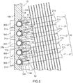
- FIG. 5 is a partial cross-sectional view showing a modification of the fixed portion of the heat pipe group 20 to the base block 10 in the cooling device 1 in FIG. 1 .
- a bent portion is provided between the first tubular portion 21a and the second tubular portion 21b by bending as described above. Accordingly, a dead space is generated where it is difficult to install a fin between the base block 10 and the lowest fin of the fin group 30. For this reason, a fin member is located in this dead space, such that this dead space is effectively utilized.
- the cooling device 1 may further include a fin member 40 located between the base block 10 and the fin group 30.
- the fin member 40 includes a plate-like base portion 41 crimped and fixed between the first tubular portion 21a and the pair of wall parts 12a and 12a, and a fin portion 42 connected to the plate-like base portion 41, and provided in a standing manner through the gap portion 13 formed between the tip end portions 12d and 12d of the pair of wall parts 12a and 12a.
- the plate-like base portion 41 extends in the longitudinal direction and the width direction, and extends along the longitudinal direction of the first tubular portion 21a (see the X-direction in FIG. 6 ). It is also preferable that the plate-like base portion 41 has a shape conforming to the outer peripheral shape of the first tubular portion 21a in cross-section in the width direction of the plate-like base portion 41. For example, in a case where the first tubular portion 21a has a circular shape in cross-sectional in the width direction, it is preferable that the plate-like base portion 41 has an arc shape in cross-section in the width direction which is coaxial to the circular shape of the first tubular portion 21a.
- the fin portion 42 extends in the longitudinal direction and the width direction similarly to the plate-like base portion 41, and extends along the longitudinal direction of the first tubular portion 21a.
- the fin portion 42 is provided along, for example, the horizontal direction.
- the fin portion 42 is provided in a standing manner along the standing direction of the second tubular portion 21b, for example, parallel to the standing direction of the second tubular portion 21b.
- the shape of the fin portion 42 in cross-section in the width direction is not limited to a particular shape, but may be, for example, a linear shape, a curved shaped, or a wavy shape.
- the fin portion 42 is thermally connected to the plate-like base portion 41 and is, for example, formed integrally with the plate-like base portion 41 in one piece, or joined to the plate-like base portion 41 by welding or other methods.
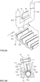
- FIG. 6A is a partially exploded perspective view of the fixed portion in FIG. 5 .
- FIG. 6B is a partially enlarged cross-sectional view of the fixed portion in FIG. 6A .
- the first tubular portion 21a of the heat pipe 21 is accommodated in the recessed part 11 of the base block 10, and further the fin member 40 is placed on the heat pipe 21 by bringing the plate-like base portion 41 into contact with the first tubular portion 21a.
- the pair of wall parts 12a and 12a is crimped in a state where the first tubular portion 21a of the heat pipe 21 is accommodated in the recessed part 11 of the base block 10, while the second tubular portion 21b of the heat pipe 21 is provided in a standing manner from the base block 10, and further the fin portion 42 of the fin member 40 is provided in a standing manner from the base block 10.
- each of the pair of wall parts 12a and 12a When the pair of wall parts 12a and 12a is in a crimped state, each of the pair of wall parts 12a and 12a includes a press-contact surface 12e that press-contacts the outer peripheral surface 21c of the first tubular portion 21a ( FIG. 6B ).
- the plate-like base portion 41 is pressed by a pair of press-contact surfaces 12e and 12e, so that the first tubular portion 21a is pressed against the recessed part 11 through the plate-like base portion 41. Both the heat pipe 21 and the plate-like base portion 41 are thereby crimped and fixed to the recessed part 11 and the pair of wall parts 12a and 12a.
- the fin member 40 is located between the base block 10 and the fin group 30.
- the dead space where it is difficult to install the fin 31 can be effectively utilized, so that the heat radiating area can be increased.
- the plate-like base portion 41 is crimped and fixed between the first tubular portion 21a and the pair of wall parts 12a and 12a.
- the fin portion 42 is connected to the plate-like base portion 41, and is provided in a standing manner through the gap portion 13 formed between the tip end portions 12d and 12d of the pair of wall parts 12a and 12a.
Landscapes
- Engineering & Computer Science (AREA)
- Microelectronics & Electronic Packaging (AREA)
- Physics & Mathematics (AREA)
- Thermal Sciences (AREA)
- Mechanical Engineering (AREA)
- Life Sciences & Earth Sciences (AREA)
- Sustainable Development (AREA)
- General Engineering & Computer Science (AREA)
- Cooling Or The Like Of Electrical Apparatus (AREA)
- Cooling Or The Like Of Semiconductors Or Solid State Devices (AREA)
Abstract
Description
- The present invention relates to a cooling device that cools electrical and electronic components and other components, and particularly relates to a cooling device that cools electrical and electronic components installed in a mobile unit such as a railway vehicle.
- A cooling device, which is used to cool a control device or other devices using a semiconductor element, has been conventionally known as cooling a heating element by using latent heat generated when refrigerant boils.
- As an example of the cooling device described above, a cooler has been proposed in which a plurality of tanks with a circular tubular shape are embedded in a base block that receives heat of a heating element such as a semiconductor element. A plurality of thin pipes are provided in a standing manner from the side of the exposed portion of the tank, and a plurality of fins are attached to the pipes, so that the cooler is capable of cooling heat of the heating element by using outside air (Patent Literature 1).
- However, the cooler with the pipes installed perpendicularly to the side of the base block is mounted on a vehicle, and when the vehicle runs on an incline, this may lead to a state where the space in the tank is partially filled with refrigerant in liquid form in the axial direction of the circular tube of the tank and then the liquid refrigerant may reach the pipes, or there is no refrigerant in liquid form at the bottom of the tank.
- Thus, to aim at improving the cooling performance, a cooler has been proposed. The cooler includes a pipe formed of a base end portion having a connection end connected to a tank embedded on one side of a base block, and a heat radiating portion bent from the base end portion and having a closed end on the tip end side. The base end portion is inclined upward from the connection end at a predetermined first inclination angle relative to the horizontal direction. The heat radiating portion is provided at a second inclination angle equal to or greater than zero degrees and smaller than the first inclination angle of the base end portion relative to the horizontal direction. In the tank, the liquid level of refrigerant is set at a position lower than the heat radiating portion (Patent Literature 2).
- However, in the cooler described above, the base block and each tank are joined integrally by soldering. Since lead solder is used in the joined portion between the base block and multiple tanks, this increases the environmental impacts.
- In view of the environmental impacts, a method using lead-free solder instead of the lead solder is considered. However, the lead-free solder has lower wettability compared to the lead solder and thus the joining force can become unstable. For this reason, there are concerns about the contact thermal conductance in a joined portion between the base block and a heat pipe, and about the resistance to vibration in the joined portion when the cooler is used in a mobile unit such as a vehicle.
- Meanwhile, a crimping method has been proposed, which does not use joining materials such as solder. In this crimping method, a base block made of metal is provided with grooves or holes in which a plurality of heat pipes are held, and is also provided with protruding portions intended for crimping. With the heat pipes accommodated in the grooves or holes, the protruding portions are crimped to fix the heat pipes to the base block (Patent Literature 3).
-
- Patent Literature 1: Japanese Patent Application Publication No.
2004-125381 - Patent Literature 2: International Publication No.
WO 2016104729 - Patent Literature 3: International Publication No.
WO 2017077619 - However, in a heat sink including a heat pipe, a fin is attached to a heat radiating portion of the heat pipe. Thus, the center-of-gravity position of the heat sink is offset toward the heat radiating portion. Thus, in the crimping method as described above, in a case where vibration or shock is applied to the heat sink, a moment of force is generated in a fixed portion of the heat pipe to the base block around the axis of the center-of-gravity position. When this moment of force is repeatedly generated, the fixed portion may become loosened and this may degrade the contact thermal conductance. Therefore, in both the method using the lead-free solder and the crimping method, there are concerns about the contact thermal conductance and the resistance to vibration.
- It is an object of the present invention to provide a cooling device that can improve the reliability of joining between a base block and a heat pipe, while reducing the environmental impacts, and can also achieve both high contact thermal conductance and high resistance to vibration, and to provide a manufacturing method of the cooling device.
- To achieve the above object, a cooling device of the present invention includes: a base block including a back-side portion thermally connectable to a heating element; a heat pipe group formed of a plurality of heat pipes, each of which includes a first tubular portion and a second tubular portion, the first tubular portion being fixed to a front-side portion of the base block and being disposed along a planar direction of the base block, the second tubular portion being connected to the first tubular portion and being provided in a standing manner from the base block; and a fin group formed of a plurality of fins fixed to the heat pipe group, the fins being parallel to each other in a standing direction of the heat pipe group, characterized in that a plurality of the first tubular portions are fixed to one another through the base block, while a plurality of the second tubular portions are fixed to one another through the fin group, the base block includes a recessed part extending in a longitudinal direction and a width direction, and having the first tubular portion accommodated therein, and a pair of wall parts protruding from opposite sides of the recessed part in the width direction along an outer peripheral surface of the first tubular portion, and the heat pipe is crimped and fixed to the recessed part and the pair of wall parts.
- It is preferable that the pair of wall parts is a pair of elongated protruding portions protruding along an outer peripheral surface of the first tubular portion, and extending along a longitudinal direction of the first tubular portion, and each of the pair of elongated protruding portions includes a press-contact surface that press-contacts an outer peripheral surface of the first tubular portion.
- It is more preferable that the pair of wall parts has an equal or nearly equal length in a protruding direction, and a gap portion with a groove-like shape is formed between tip end portions of the pair of wall parts.
- The cooling device may further include a fin member located between the base block and the fin group, wherein the fin member may include a plate-like base portion crimped and fixed between the first tubular portion and the pair of wall parts, and a fin portion connected to the plate-like base portion and provided in a standing manner through the gap portion formed between the tip end portions of the pair of wall parts.
- The base block may be located along a vertical direction. The first tubular portion of the heat pipe may be provided along a horizontal direction. The second tubular portion of the heat pipe may be inclined upward toward a tip end relative to a thickness direction of the base block.
- The pair of wall parts may protrude at an angle equal to, or nearly equal to, a standing angle of the second tubular portion relative to the base block.
- To achieve the above object, a manufacturing method of a cooling device of the present invention is characterized by including: a base-block forming step of forming a plurality of recessed parts, each of which extends in a longitudinal direction and a width direction, on a front-side portion of a base block, and further forming a pair of wall parts protruding linearly from opposite sides of each of the recessed parts in the width direction, while being inclined relative to a thickness direction of the base block; a crimping step of preparing a plurality of heat pipes, each of which includes a first tubular portion and a second tubular portion connected to the first tubular portion, and crimping the pair of wall parts in a state where the first tubular portion of the heat pipe is accommodated in the recessed part of the base block, and the second tubular portion of the heat pipe is provided in a standing manner from the base block; and a fin-group forming step of forming a fin group by fixing a plurality of fins to a heat pipe group formed of the heat pipes crimped to the base block, the fins being parallel to each other in a standing direction of the heat pipe group.
- It is preferable that in the base-block forming step, the pair of wall parts having an equal or nearly equal length in an extending direction is formed, and in the crimping step, the pair of wall parts is pressed by a pressing force in a vertical direction in a state where the base block is inclined such that a pair of tip end portions of the pair of wall parts is maintained at a same height.
- In the crimping step, in a state where the pair of wall parts protrudes in a vertical direction, a pressing force in the vertical direction may be applied to the pair of wall parts.
- In the crimping step, a jig including a groove portion with an inverted U-shape may be used to press the groove portion against the pair of wall parts to press the pair of wall parts together.
- According to a cooling device of the present invention, the reliability of joining between the base block and the heat pipe can be improved, while the environmental impacts are reduced, and high contact thermal conductance and high resistance to vibration can both be achieved.
-
- [
FIG. 1 ] A schematic cross-sectional view showing the configuration of a cooling device according to an embodiment of the present invention. - [
FIG. 2 ] A partial cross-sectional view showing the detailed configuration of the cooling device inFIG. 1 . - [
FIG. 3A ] A cross-sectional view showing the detailed configuration of a base block after a heat pipe group has been fixed to the base block. - [
FIG. 3B ] A partially enlarged perspective view of the fixed portion inFIG. 3A . - [
FIG. 3C ] A cross-sectional view showing the detailed configuration of the base block before the heat pipe group is fixed to the base block. - [
FIGs. 4A to 4D ] Explanatory views for describing an example of a manufacturing method of the cooling device inFIG. 1 . - [
FIG. 5 ] A partial cross-sectional view showing a modification of the fixed portion of the heat pipe group to the base block in the cooling device inFIG. 1 . - [
FIG. 6A ] A partially exploded perspective view of the fixed portion inFIG. 5 . - [
FIG. 6B ] A partially enlarged cross-sectional view of the fixed portion inFIG. 6A . - Hereinafter, an embodiment of the present invention is described in detail with reference to the drawings.
-
FIG. 1 is a schematic cross-sectional view showing the configuration of a cooling device according to an embodiment of the present invention. In the present embodiment, a railway vehicle is described as an example of a mobile unit having the cooling device installed therein. Note that the configuration of the cooling device and the installation position of the cooling device shown inFIG. 1 are merely an example. The cooling device of the present invention and the installation position of this cooling device are not limited to those shown inFIG. 1 . - As shown in
FIG. 1 , acasing 200 in a sealed state is attached to anunderfloor surface 101 of avehicle 100 through anattachment 102. Oneside wall 201 of thecasing 200 is formed with anopening 202. An opening-closing cover 203 that opens or closes theopening 202 is attached to theside wall 201 through ahinge 204 at the upper portion of theside wall 201. The opening-closing cover 203 is configured to be locked by a locking means (not shown) when the opening-closing cover 203 closes theopening 202. - Another
side wall 205 of thecasing 200 is formed with awindow hole 206. Thewindow hole 206 is closed by abase block 10 attached to theside wall 205 on the outside of theside wall 205. Thecasing 200 is thereby held in a sealed state. A plurality ofelectrical components 300, such as a heating element that is, for example, a semiconductor module, are attached to a part of thebase block 10, which faces the interior of thecasing 200. Inside thecasing 200,other components - On the
side wall 205 of thecasing 200, atubular cover 207 is attached such that thecover 207 extends along the airflow generated by running of thevehicle 100. Inside thecover 207, a cooling device 1 is accommodated.Support plates heat pipe group 20 are also attached to the inside of thecover 207. Thesupport plate 208a supports theheat pipe group 20 from below. For example, one end portion of thesupport plate 208a is fixed to abottom wall 209 of thecover 207, while the other end portion of thesupport plate 208a is fixed to a part of theheat pipe group 20. Thesupport plate 208b supports theheat pipe group 20 from above. For example, one end portion of thesupport plate 208b is fixed to atop wall 210 of thecover 207, while the other end portion of thesupport plate 208b is fixed to a part of theheat pipe group 20. Thesupport plates heat pipe group 20, and also serve as a heat radiating plate. -
FIG. 2 is a partial cross-sectional view showing the detailed configuration of the cooling device 1 inFIG. 1 . As shown inFIG. 2 , the cooling device 1 includes thebase block 10 including a back-side portion 10a thermally connected to theelectrical components 300 that are heating elements, theheat pipe group 20 formed of a plurality ofheat pipes 21, each of which includes a firsttubular portion 21a and a secondtubular portion 21b, the firsttubular portion 21a being fixed to a front-side portion 10b of thebase block 10 and being disposed along the planar direction of thebase block 10, the secondtubular portion 21b being connected to the firsttubular portion 21a and being provided in a standing manner from thebase block 10, and afin group 30 formed of a plurality offins heat pipe group 20, thefins heat pipe group 20. - The
base block 10 is attached to thecasing 200 along theside wall 205 in such a manner that the back-side portion 10a faces toward thecasing 200, while the front-side portion 10b faces toward the cover 207 (FIG. 1 ). For example, thebase block 10 is located along the vertical direction. Thebase block 10 is made of metal material such as aluminum or aluminum alloy, or copper or copper alloy. - A plurality of
heat pipes heat pipe group 20 are provided next to and spaced apart from each other in an up-down direction, for example, in the vertical direction. Each of theheat pipes 21 is formed of a tubular member having, for example, a U-shape (seeFIG. 6 ). - The first
tubular portion 21a has, for example, a circular tubular shape, and is filled with an amount of operating fluid equivalent to between 30% and 40% of the overall volume. The secondtubular portion 21b has, for example, a circular tubular shape that is the same as the shape of the firsttubular portion 21a. The firsttubular portion 21a and the secondtubular portion 21b may have a circular shape, an oval shape, or other shape in cross-section in the width direction. - The first
tubular portion 21a has a function of a heated portion to be heated by heat from thebase block 10. The secondtubular portion 21b has a function of a heat radiating portion that radiates heat from the firsttubular portion 21a. As long as the firsttubular portion 21a and the secondtubular portion 21b are configured to implement their respective functions described above, the shape of theheat pipe 21 is not limited, but may be an L-shape or a looped shape, for example. The firsttubular portion 21a and the secondtubular portion 21b may be formed in one piece by bending a long pipe or other methods, or may be connected together by joining such as welding. - The
fins fin group 30 are provided next to and spaced apart from each other in the standing direction of the secondtubular portion 21b such that, for example, the main surfaces of thefins fin 31 includes one or a plurality of holes corresponding to the positions of theheat pipes 21. Thefin 31 is fixed to theheat pipes 21 by, for example, press fitting. - The
fin 31 has a function of the heat radiating portion that radiates heat from the secondtubular portion 21b. That is, thefin 31 constitutes the heat radiating portion in cooperation with the secondtubular portion 21b. As long as thefin 31 is configured to implement the function described above, the shape of thefin 31 is not limited. - It is preferable that the
fin 31 is connected with all theheat pipes heat pipe group 20 in which theheat pipes fin 32 may also be provided, which is connected with some of theheat pipes heat pipe group 20 in which theheat pipes - In the present embodiment, a plurality of first
tubular portions base block 10, while a plurality of secondtubular portions fin group 30. That is, thefin group 30, formed of thefins heat pipes heat pipe group 20 and thefin group 30, the respective distances between theheat pipes fin group 30. This results in a structure in which a moment of force is minimally generated in each fixed portion between thebase block 10 and each of theheat pipes 21 provided in a standing manner from thebase block 10. - It is preferable to install the cooling device 1 below the
underfloor surface 101 of thevehicle 100. In this case, for example, thebase block 10 is located along the vertical direction, the firsttubular portion 21a of theheat pipe 21 is provided along the horizontal direction, and the secondtubular portion 21b of theheat pipe 21 is inclined upward toward the tip end of the secondtubular portion 21b relative to the thickness direction of the base block 10 (FIG. 1 ). It is also preferable to provide the firsttubular portion 21a with the longitudinal direction (axial direction) of the firsttubular portion 21a extending along the traveling direction of thevehicle 100. It is further preferable to provide thefin 31 along the traveling direction of thevehicle 100. This can improve the cooling efficiency. - In the cooling device 1, heat from the
electrical components 300 and heat in thecasing 200 generated from theother components base block 10 to the firsttubular portion 21a of theheat pipe 21, then transferred to the secondtubular portion 21b by a change in phase of the operating fluid in the interior of the firsttubular portion 21a, and radiated to the exterior of the secondtubular portion 21b through thefin 31. - Next, the detailed configuration of the fixed portion of the
heat pipe 21 to thebase block 10 is described. -
FIG. 3A is a cross-sectional view showing the detailed configuration of thebase block 10 after theheat pipe group 20 has been fixed to thebase block 10.FIG. 3B is a partially enlarged perspective view of the fixed portion inFIG. 3A. FIG. 3C is a cross-sectional view showing the configuration of thebase block 10 before theheat pipe group 20 is fixed to thebase block 10. - As shown in
FIGs. 3A to 3C , thebase block 10 includes a recessedpart 11 extending in the longitudinal direction and the width direction and having the firsttubular portion 21a accommodated therein, and a pair ofwall parts part 11 in the width direction along the outer peripheral surface of the firsttubular portion 21a. Theheat pipe 21 is crimped and fixed to the recessedpart 11 and the pair ofwall parts - The recessed
part 11 is provided along the planar direction of thebase block 10 such that, for example, the longitudinal direction of the recessedpart 11 extends horizontally, while the width direction of the recessedpart 11 extends vertically. It is preferable to provide the recessedpart 11 with the longitudinal direction of the recessedpart 11 extending along the traveling direction of the vehicle 100 (seeFIG. 1 ). - The pair of
wall parts base block 10 in the same manner as the recessedpart 11. It is preferable that thewall part 12a extends along, for example, the extending direction of the recessedpart 11, and extends parallel to the extending direction of the recessedpart 11. The pair ofwall parts part 11 in cross-section in the width direction, and is bent toward the center of the recessedpart 11 in the width direction such that thewall parts wall parts wall parts tubular portion 21b relative to thebase block 10. Particularly, in a case where the secondtubular portion 21b of theheat pipe 21 is inclined upward toward the tip end of the secondtubular portion 21b relative to the thickness direction of thebase block 10, the pair ofwall parts tubular portion 21b inclined upward toward the tip end. - It is preferable that the pair of
wall parts peripheral surface 21c of the firsttubular portion 21a, and extending along the longitudinal direction (the X-direction in the drawing) of the firsttubular portion 21a (FIG. 3B ). In this case, each of the pair of elongated protruding portions includes a press-contact surface 12c that press-contacts the outerperipheral surface 21c of the firsttubular portion 21a. The pair of elongated protruding portions includes a pair of press-contact surfaces tubular portion 21a and the pair of elongated protruding portions is increased and accordingly a friction force is increased. - It is preferable that the pair of
wall parts wall parts wall parts gap portion 13 with a groove-like shape may be formed between a pair oftip end portions wall parts wall parts gap portion 13 with a groove-like shape has a minute width from the viewpoint of the contact area described above. - Before the
heat pipe group 20 is fixed to thebase block 10, the pair ofwall parts base block 10, that is, relative to a direction perpendicular to the front-side portion 10b as shown inFIG. 3C . The inclination angle of the pair ofwall parts base block 10, for example (80 degrees with respect to the planar direction of the base block 10). When the pair ofwall parts base block 10, then an equal or nearly equal pressing force can be simultaneously applied to both of the pair ofwall parts base block 10 is provided with a plurality of pairs ofwall parts parts 11. It is preferable that the pairs ofwall parts wall parts tubular portion 21b relative to thebase block 10. Particularly, in a case where the secondtubular portion 21b of theheat pipe 21 is inclined upward toward the tip end of the secondtubular portion 21b relative to the thickness direction of thebase block 10, the pair ofwall parts tubular portion 21b inclined upward toward the tip end. - Next, a manufacturing method of the cooling device 1 in
FIG. 1 is described with reference toFIGs. 4A to 4D . The manufacturing method of the cooling device shown inFIGs. 4 is merely an example. The manufacturing method of a cooling device of the present invention is not limited to that shown inFIGs. 4 . - First, a plurality of the recessed
parts 11, each of which extends in the longitudinal direction and the width direction, are formed on the front-side portion 10b of thebase block 10. Further, the pair ofwall parts wall parts wall parts base block 10 is thereby obtained as shown inFIG. 3C . - Thereafter, a press-fitting
base 401 including aninclined portion 401a is mounted on a work table 400, and thebase block 10 having been manufactured is placed on theinclined portion 401a and then fixed by using a jig (not shown) (FIG. 4A ). At this time, it is preferable to set the inclination angle of theinclined portion 401a such that the pair ofwall parts wall parts inclined portion 401a is set to 10 degrees with respect to the horizontal direction. In a case where the pair ofwall parts base block 10 such that the pair oftip end portions wall parts - Thereafter, a plurality of the
heat pipes 21 are prepared, each of which includes the firsttubular portion 21a and the secondtubular portion 21b connected to thistubular portion 21a, to accommodate the firsttubular portion 21a of theheat pipe 21 in the recessedpart 11 of the base block 10 (FIG. 4B ). At this time, for example, the secondtubular portion 21b of eachheat pipe 21 is provided in a standing manner from thebase block 10 in the vertical direction. It is preferable to hold theheat pipe 21 such that the secondtubular portion 21b is provided in a standing manner in a direction parallel to the pair ofwall parts - Thereafter, the pair of
wall parts tubular portion 21a of theheat pipe 21 is accommodated in the recessedpart 11 of thebase block 10, and where the secondtubular portion 21b of theheat pipe 21 is provided in a standing manner from the base block 10 (crimping step) (FIG. 4C ). For example, ajig 402 is used, thejig 402 including agroove portion 402b having an inverted U-shape on abottom portion 402a. Thejig 402 is moved downward in the vertical direction (the arrow direction in the drawing) to press thegroove portion 402b against the pair ofwall parts wall parts - In a case where the pair of
wall parts wall parts base block 10 is inclined such that the pair oftip end portions wall parts wall parts wall parts - The first
tubular portion 21a is thereby crimped and fixed to the recessedpart 11 and the pair ofwall parts FIG. 4D ). The crimping step described above is repeatedly performed on theheat pipes 21, so that theheat pipes 21 are fixed to one another through thebase block 10. - In a case where the pair of
wall parts wall parts wall parts wall parts groove portion 402b in the width direction aligns with the center position of the pair ofwall parts jig 402. - The curved-surface shape of the
groove portion 402b of thejig 402 is not limited to a particular shape. However, it is preferable that thegroove portion 402b has a line-symmetric curved-surface shape with respect to the vertical direction from the viewpoint of applying a pressing force evenly to the pair ofwall parts wall parts wall part 12a has a uniform thickness, it is preferable that thegroove portion 402b has a curved-surface shape conforming to the outer peripheral shape of the firsttubular portion 21a from the viewpoint of increasing the contact area between the firsttubular portion 21a and the pair ofwall parts groove portion 402b has a circular curved-surface shape. - Then, a fin group is formed by fixing a plurality of fins to the
heat pipe group 20 formed of theheat pipes 21 fixed to thebase block 10, the fins being parallel to each other in the standing direction of the heat pipe group 20 (fin-group forming step). The secondtubular portions fin group 30. - As described above, according to the present embodiment, the first
tubular portions base block 10, and the secondtubular portions fin group 30. Thus, even when vibration or shock acts on the heat sink, the respective distances between theheat pipes base block 10 and each of theheat pipes 21 provided in a standing manner from thebase block 10. Consequently, a fixing force between thebase block 10 and each of theheat pipes 21 is maintained. Therefore, the reliability of joining between thebase block 10 and theheat pipe 21 is improved, and high contact thermal conductance and high resistance to vibration can both be achieved. In addition, since it is unnecessary to use lead-free solder, the environmental impacts can be reduced, and this can meet the specifications of a cooling device that is conditional to avoiding the use of lead solder. - The
heat pipe 21 is crimped and fixed to the recessedpart 11 and the pair ofwall parts base block 10, so that theheat pipe 21 can be rigidly joined to thebase block 10. Particularly, the environmental impacts can be reduced compared to the lead solder, and also theheat pipe 21 is less affected by wettability or other factors as compared to the lead-free solder, so that a stable joining force can be maintained. - Further, the pair of
wall parts peripheral surface 21c of the firsttubular portion 21a, and extending along the longitudinal direction of the firsttubular portion 21a. Each of the pair of elongated protruding portions includes the press-contact surface 12c that press-contacts the outerperipheral surface 21c of the firsttubular portion 21a. Thus, a friction force generated between the firsttubular portion 21a and the pair of elongated protruding portions can be increased, so that theheat pipe 21 can be more rigidly joined to thebase block 10. - According to the present embodiment, a plurality of the
heat pipes 21 are prepared, each of which includes the firsttubular portion 21a and the secondtubular portion 21b, and the pair ofwall parts tubular portion 21a of theheat pipe 21 is accommodated in the recessedpart 11 of thebase block 10, and the secondtubular portion 21b of theheat pipe 21 is provided in a standing manner from the base block 10 (crimping step). Then, thefin group 30 is formed by fixing a plurality of thefins heat pipe group 20 formed of theheat pipes base block 10, thefins base block 10 and theheat pipe 21, and having both high contact thermal conductance and high resistance to vibration. -
FIG. 5 is a partial cross-sectional view showing a modification of the fixed portion of theheat pipe group 20 to thebase block 10 in the cooling device 1 inFIG. 1 . In a case where the firsttubular portion 21a and the secondtubular portion 21b of theheat pipe 21 are formed in one piece, a bent portion is provided between the firsttubular portion 21a and the secondtubular portion 21b by bending as described above. Accordingly, a dead space is generated where it is difficult to install a fin between thebase block 10 and the lowest fin of thefin group 30. For this reason, a fin member is located in this dead space, such that this dead space is effectively utilized. - For example, as shown in
FIG. 5 , the cooling device 1 may further include afin member 40 located between thebase block 10 and thefin group 30. Thefin member 40 includes a plate-like base portion 41 crimped and fixed between the firsttubular portion 21a and the pair ofwall parts fin portion 42 connected to the plate-like base portion 41, and provided in a standing manner through thegap portion 13 formed between thetip end portions wall parts - It is preferable that the plate-
like base portion 41 extends in the longitudinal direction and the width direction, and extends along the longitudinal direction of the firsttubular portion 21a (see the X-direction inFIG. 6 ). It is also preferable that the plate-like base portion 41 has a shape conforming to the outer peripheral shape of the firsttubular portion 21a in cross-section in the width direction of the plate-like base portion 41. For example, in a case where the firsttubular portion 21a has a circular shape in cross-sectional in the width direction, it is preferable that the plate-like base portion 41 has an arc shape in cross-section in the width direction which is coaxial to the circular shape of the firsttubular portion 21a. - It is preferable that the
fin portion 42 extends in the longitudinal direction and the width direction similarly to the plate-like base portion 41, and extends along the longitudinal direction of the firsttubular portion 21a. In this case, thefin portion 42 is provided along, for example, the horizontal direction. - The
fin portion 42 is provided in a standing manner along the standing direction of the secondtubular portion 21b, for example, parallel to the standing direction of the secondtubular portion 21b. The shape of thefin portion 42 in cross-section in the width direction is not limited to a particular shape, but may be, for example, a linear shape, a curved shaped, or a wavy shape. Thefin portion 42 is thermally connected to the plate-like base portion 41 and is, for example, formed integrally with the plate-like base portion 41 in one piece, or joined to the plate-like base portion 41 by welding or other methods. -
FIG. 6A is a partially exploded perspective view of the fixed portion inFIG. 5 .FIG. 6B is a partially enlarged cross-sectional view of the fixed portion inFIG. 6A . In a case where thefin member 40 inFIG. 5 is attached to theheat pipe 21, prior to the crimping step in the manufacturing method described above, the firsttubular portion 21a of theheat pipe 21 is accommodated in the recessedpart 11 of thebase block 10, and further thefin member 40 is placed on theheat pipe 21 by bringing the plate-like base portion 41 into contact with the firsttubular portion 21a. At this time, it is preferable to hold thefin member 40 such that thefin portion 42 of thefin member 40 extends parallel to the standing direction of the secondtubular portion 21b. - Then, the pair of
wall parts tubular portion 21a of theheat pipe 21 is accommodated in the recessedpart 11 of thebase block 10, while the secondtubular portion 21b of theheat pipe 21 is provided in a standing manner from thebase block 10, and further thefin portion 42 of thefin member 40 is provided in a standing manner from thebase block 10. - When the pair of
wall parts wall parts contact surface 12e that press-contacts the outerperipheral surface 21c of the firsttubular portion 21a (FIG. 6B ). The plate-like base portion 41 is pressed by a pair of press-contact surfaces tubular portion 21a is pressed against the recessedpart 11 through the plate-like base portion 41. Both theheat pipe 21 and the plate-like base portion 41 are thereby crimped and fixed to the recessedpart 11 and the pair ofwall parts - According to the present modification, the
fin member 40 is located between thebase block 10 and thefin group 30. Thus, the dead space where it is difficult to install thefin 31 can be effectively utilized, so that the heat radiating area can be increased. - The plate-
like base portion 41 is crimped and fixed between the firsttubular portion 21a and the pair ofwall parts fin portion 42 is connected to the plate-like base portion 41, and is provided in a standing manner through thegap portion 13 formed between thetip end portions wall parts heat pipe 21 is fixed to thebase block 10, thefin member 40 can be crimped jointly with theheat pipe 21. Accordingly, a heat sink with an increased heat radiating area while maintaining the contact area can be easily manufactured. - While the cooling device and the manufacturing method of a cooling device according to the present embodiment have been described above, the present invention is not limited to the aforementioned embodiment, but various modifications and variations are possible based on the technical scope of the present invention.
-
- 1
- cooling device
- 10
- base block
- 10a
- back-side portion
- 10b
- front-side portion
- 11
- recessed part
- 12a, 12a
- pair of wall parts
- 12c
- press-contact surface
- 12d, 12d
- pair of tip end portions
- 12e
- press-contact surface
- 13
- gap portion
- 20
- heat pipe group
- 21
- heat pipe
- 21a
- first tubular portion
- 21b
- second tubular portion
- 21c
- outer peripheral surface
- 31
- fin
- 30
- fin group
- 40
- fin member
- 41
- plate-like base portion
- 42
- fin portion
- 100
- vehicle
- 101
- underfloor surface
- 102
- attachment
- 200
- casing
- 201
- side wall
- 202
- opening
- 203
- opening-closing cover
- 204
- hinge
- 205
- side wall
- 206
- window hole
- 207
- cover
- 208a, 208b
- support plate
- 300
- electrical component
- 301, 302, 303
- other components
- 400
- work table
- 401
- press-fitting base
- 401a
- inclined portion
- 402
- jig
- 402a
- bottom portion
- 402b
- groove portion
Claims (10)
- A cooling device comprising:a base block including a back-side portion thermally connectable to a heating element;a heat pipe group formed of a plurality of heat pipes, each of which includes a first tubular portion and a second tubular portion, the first tubular portion being fixed to a front-side portion of the base block and being disposed along a planar direction of the base block, the second tubular portion being connected to the first tubular portion and being provided in a standing manner from the base block; anda fin group formed of a plurality of fins fixed to the heat pipe group, the fins being parallel to each other in a standing direction of the heat pipe group, whereina plurality of the first tubular portions are fixed to one another through the base block, while a plurality of the second tubular portions are fixed to one another through the fin group,the base block includesa recessed part extending in a longitudinal direction and a width direction, and having the first tubular portion accommodated therein, anda pair of wall parts protruding from opposite sides of the recessed part in the width direction along an outer peripheral surface of the first tubular portion, andthe heat pipe is crimped and fixed to the recessed part and the pair of wall parts.
- The cooling device according to claim 1, wherein
the pair of wall parts is a pair of elongated protruding portions protruding along the outer peripheral surface of the first tubular portion, and extending along the longitudinal direction of the first tubular portion, and
each of the pair of elongated protruding portions includes a press-contact surface that press-contacts the outer peripheral surface of the first tubular portion. - The cooling device according to claim 1 or 2, wherein
the pair of wall parts has an equal or nearly equal length in a protruding direction, and
a gap portion with a groove-like shape is formed between tip end portions of the pair of wall parts. - The cooling device according to any one of claims 1 to 3, further comprising a fin member located between the base block and the fin group, wherein
the fin member includes a plate-like base portion crimped and fixed between the first tubular portion and the pair of wall parts, and a fin portion connected to the plate-like base portion and provided in a standing manner through the gap portion formed between the tip end portions of the pair of wall parts. - The cooling device according to any one of claims 1 to 4, wherein
the base block is located along a vertical direction,
the first tubular portion of the heat pipe is provided along a horizontal direction, and
the second tubular portion of the heat pipe is inclined upward toward a tip end relative to a thickness direction of the base block. - The cooling device according to any one of claims 1 to 5, wherein the pair of wall parts protrudes at an angle equal to, or nearly equal to, a standing angle of the second tubular portion relative to the base block.
- A manufacturing method of a cooling device, characterized by comprising:a base-block forming step of forming a plurality of recessed parts, each of which extends in a longitudinal direction and a width direction, on a front-side portion of a base block, and further forming a pair of wall parts protruding linearly from opposite sides of each of the recessed parts in the width direction, while being inclined relative to a thickness direction of the base block;a crimping step of preparing a plurality of heat pipes, each of which includes a first tubular portion and a second tubular portion connected to the first tubular portion, and crimping the pair of wall parts in a state where the first tubular portion of the heat pipe is accommodated in the recessed part of the base block, and the second tubular portion of the heat pipe is provided in a standing manner from the base block; anda fin-group forming step of forming a fin group by fixing a plurality of fins to a heat pipe group formed of the heat pipes crimped to the base block, the fins being parallel to each other in a standing direction of the heat pipe group.
- The manufacturing method of the cooling device according to claim 7, wherein
in the base-block forming step, the pair of wall parts having an equal or nearly equal length in an extending direction is formed, and
in the crimping step, the pair of wall parts is pressed by a pressing force in a vertical direction in a state where the base block is inclined such that a pair of tip end portions of the pair of wall parts is maintained at a same height. - The manufacturing method of the cooling device according to claim 7 or 8, wherein in the crimping step, in a state where the pair of wall parts protrudes in a vertical direction, a pressing force in the vertical direction is applied to the pair of wall parts.
- The manufacturing method of the cooling device according to claim 8 or 9, wherein in the crimping step, a jig including a groove portion with an inverted U-shape is used to press the groove portion against the pair of wall parts to press the pair of wall parts together.
Applications Claiming Priority (2)
| Application Number | Priority Date | Filing Date | Title |
|---|---|---|---|
| JP2017253884 | 2017-12-28 | ||
| PCT/JP2018/048047 WO2019131834A1 (en) | 2017-12-28 | 2018-12-27 | Cooling device |
Publications (3)
| Publication Number | Publication Date |
|---|---|
| EP3734214A1 true EP3734214A1 (en) | 2020-11-04 |
| EP3734214A4 EP3734214A4 (en) | 2021-09-22 |
| EP3734214B1 EP3734214B1 (en) | 2023-09-06 |
Family
ID=67067584
Family Applications (1)
| Application Number | Title | Priority Date | Filing Date |
|---|---|---|---|
| EP18896705.3A Active EP3734214B1 (en) | 2017-12-28 | 2018-12-27 | Cooling device |
Country Status (5)
| Country | Link |
|---|---|
| EP (1) | EP3734214B1 (en) |
| JP (1) | JP7222920B2 (en) |
| CN (1) | CN111670332B (en) |
| TW (1) | TWI694233B (en) |
| WO (1) | WO2019131834A1 (en) |
Cited By (1)
| Publication number | Priority date | Publication date | Assignee | Title |
|---|---|---|---|---|
| WO2023035172A1 (en) * | 2021-09-09 | 2023-03-16 | Telefonaktiebolaget Lm Ericsson (Publ) | A heatsink fin, a heatsink provided therewith, a heat exchange arrangement provided with the heat sink and method of manufacturing a heatsink fin |
Families Citing this family (2)
| Publication number | Priority date | Publication date | Assignee | Title |
|---|---|---|---|---|
| TWI831706B (en) * | 2023-06-13 | 2024-02-01 | 大陸商奇宏電子(深圳)有限公司 | Heating jig |
| CN117948279B (en) * | 2024-01-30 | 2024-10-18 | 至正实业枣阳市有限公司 | Vacuum device for extruder |
Family Cites Families (23)
| Publication number | Priority date | Publication date | Assignee | Title |
|---|---|---|---|---|
| JPS599495A (en) * | 1982-07-09 | 1984-01-18 | Matsushita Electric Ind Co Ltd | Heat pipe type radiator |
| JPS6083255U (en) * | 1983-11-15 | 1985-06-08 | 昭和アルミニウム株式会社 | heat dissipation device |
| CN1103946A (en) * | 1993-12-18 | 1995-06-21 | 芹泽英璋 | Raditation plate and method of producing the same |
| US5826645A (en) * | 1997-04-23 | 1998-10-27 | Thermal Corp. | Integrated circuit heat sink with rotatable heat pipe |
| WO1999039145A1 (en) * | 1998-01-30 | 1999-08-05 | Hitachi, Ltd. | Heat pipe type cooling device, method of producing the same and cooling plate for heat pipe type cooling device |
| JPH11351769A (en) * | 1998-06-12 | 1999-12-24 | Furukawa Electric Co Ltd:The | heatsink |
| JP4204681B2 (en) * | 1998-11-20 | 2009-01-07 | 住友軽金属工業株式会社 | Heat pipe fixing structure |
| CN2560098Y (en) * | 2002-07-23 | 2003-07-09 | 华为技术有限公司 | Heat tube radiating apparatus |
| JP2004125381A (en) * | 2002-08-02 | 2004-04-22 | Mitsubishi Alum Co Ltd | Heat pipe unit and heat pipe cooler |
| CN2736931Y (en) * | 2004-09-28 | 2005-10-26 | 陈世明 | Stamping structure of heat pipe radiator |
| TWM280631U (en) * | 2005-07-21 | 2005-11-11 | Shr-Ming Chen | Tight-fitting structure of heat dissipater base and heat pipe |
| CN100543972C (en) * | 2005-08-08 | 2009-09-23 | 富准精密工业(深圳)有限公司 | heat pipe radiator |
| JP2007218439A (en) * | 2006-02-14 | 2007-08-30 | Sumitomo Light Metal Ind Ltd | Fixing the heat pipe |
| US7441592B2 (en) * | 2006-11-26 | 2008-10-28 | Tsung-Hsien Huang | Cooler module |
| TW200908862A (en) * | 2007-08-10 | 2009-02-16 | Ama Precision Inc | Heat conductive module and manufacturing method thereof |
| CN101160034A (en) * | 2007-08-31 | 2008-04-09 | 王亚雄 | Heat pipe cooling radiator for high power power electronics |
| US20110162206A1 (en) | 2010-01-07 | 2011-07-07 | Shyh-Ming Chen | Method for connecting heat-dissipating fin and heat pipe |
| US9429370B1 (en) * | 2014-05-27 | 2016-08-30 | Unigen Corporation | Heat sink with flat heat pipe |
| JP6505130B2 (en) | 2014-12-25 | 2019-04-24 | 三菱アルミニウム株式会社 | Cooler |
| WO2016104728A1 (en) * | 2014-12-25 | 2016-06-30 | 三菱アルミニウム株式会社 | Cooler |
| WO2017077619A1 (en) | 2015-11-05 | 2017-05-11 | 古河電気工業株式会社 | Heat pipe fixing structure and heat pipe fixing method |
| CN106239077B (en) * | 2016-08-16 | 2018-09-21 | 安徽天祥空调科技有限公司 | A kind of air-conditioning heat exchanger heat exchange fin and preparation method thereof |
| CN207976030U (en) * | 2018-03-07 | 2018-10-16 | 上海珊泽精密金属制品有限公司 | Heat radiating apparatus for vehicle |
-
2018
- 2018-12-27 CN CN201880084733.4A patent/CN111670332B/en active Active
- 2018-12-27 EP EP18896705.3A patent/EP3734214B1/en active Active
- 2018-12-27 WO PCT/JP2018/048047 patent/WO2019131834A1/en not_active Ceased
- 2018-12-27 JP JP2019562144A patent/JP7222920B2/en active Active
- 2018-12-28 TW TW107147645A patent/TWI694233B/en active
Cited By (1)
| Publication number | Priority date | Publication date | Assignee | Title |
|---|---|---|---|---|
| WO2023035172A1 (en) * | 2021-09-09 | 2023-03-16 | Telefonaktiebolaget Lm Ericsson (Publ) | A heatsink fin, a heatsink provided therewith, a heat exchange arrangement provided with the heat sink and method of manufacturing a heatsink fin |
Also Published As
| Publication number | Publication date |
|---|---|
| JP7222920B2 (en) | 2023-02-15 |
| JPWO2019131834A1 (en) | 2020-12-10 |
| CN111670332A (en) | 2020-09-15 |
| TW201932781A (en) | 2019-08-16 |
| WO2019131834A1 (en) | 2019-07-04 |
| CN111670332B (en) | 2022-02-01 |
| TWI694233B (en) | 2020-05-21 |
| EP3734214A4 (en) | 2021-09-22 |
| EP3734214B1 (en) | 2023-09-06 |
Similar Documents
| Publication | Publication Date | Title |
|---|---|---|
| US7613004B2 (en) | Heat sink with heat dissipating fins and method of manufacturing heat sink | |
| US9565786B2 (en) | Sheet-like heat pipe, and electronic device provided with same | |
| US7128131B2 (en) | Heat sink for electronic devices and heat dissipating method | |
| EP3734214B1 (en) | Cooling device | |
| EP1387139B1 (en) | Heat pipe type heat exchanger | |
| US20170208706A1 (en) | Multi-level oscillating heat pipe implementation in an electronic circuit card module | |
| CN113056344B (en) | Heat pipe structure, heat sink, method for manufacturing heat pipe structure, and method for manufacturing heat sink | |
| US20030024691A1 (en) | High efficiency heat sink | |
| JP2006156465A (en) | Heat dissipating member and outdoor communication device having the heat dissipating member | |
| JP6156368B2 (en) | COOLING DEVICE CONNECTION STRUCTURE, COOLING DEVICE, AND COOLING DEVICE CONNECTION METHOD | |
| US20150075761A1 (en) | Heat sink attachment to tube | |
| US20090314471A1 (en) | Heat pipe type heat sink and method of manufacturing the same | |
| US11039549B2 (en) | Heat transferring module | |
| US10986756B2 (en) | Cooling apparatus for an electrical component | |
| US20060113662A1 (en) | Micro heat pipe with wedge capillaries | |
| JP3181915U (en) | Radiator | |
| JP2016086134A (en) | Heat sink, heat sink integrated power module, and manufacturing method thereof | |
| CN220402031U (en) | Heat dissipation structure | |
| US20140352925A1 (en) | Heat pipe structure | |
| JP3123335B2 (en) | Air-cooled heat sink | |
| US11964317B2 (en) | Heat pipe structure and caulking jig for heat pipe structure | |
| JP2006196786A (en) | Heat sink with heat pipe | |
| CN223488593U (en) | heat sink | |
| CN223428731U (en) | Heat dissipation mechanism | |
| KR20250038174A (en) | Heat dissipation apparatus and manufacturing method of the same |
Legal Events
| Date | Code | Title | Description |
|---|---|---|---|
| STAA | Information on the status of an ep patent application or granted ep patent |
Free format text: STATUS: THE INTERNATIONAL PUBLICATION HAS BEEN MADE |
|
| PUAI | Public reference made under article 153(3) epc to a published international application that has entered the european phase |
Free format text: ORIGINAL CODE: 0009012 |
|
| STAA | Information on the status of an ep patent application or granted ep patent |
Free format text: STATUS: REQUEST FOR EXAMINATION WAS MADE |
|
| 17P | Request for examination filed |
Effective date: 20200629 |
|
| AK | Designated contracting states |
Kind code of ref document: A1 Designated state(s): AL AT BE BG CH CY CZ DE DK EE ES FI FR GB GR HR HU IE IS IT LI LT LU LV MC MK MT NL NO PL PT RO RS SE SI SK SM TR |
|
| AX | Request for extension of the european patent |
Extension state: BA ME |
|
| DAV | Request for validation of the european patent (deleted) | ||
| DAX | Request for extension of the european patent (deleted) | ||
| A4 | Supplementary search report drawn up and despatched |
Effective date: 20210820 |
|
| RIC1 | Information provided on ipc code assigned before grant |
Ipc: H05K 7/20 20060101ALI20210816BHEP Ipc: F28D 15/02 20060101AFI20210816BHEP |
|
| REG | Reference to a national code |
Ref legal event code: R079 Free format text: PREVIOUS MAIN CLASS: F28D0015020000 Ref country code: DE Ref legal event code: R079 Ref document number: 602018057269 Country of ref document: DE Free format text: PREVIOUS MAIN CLASS: F28D0015020000 Ipc: B21D0039060000 |
|
| GRAP | Despatch of communication of intention to grant a patent |
Free format text: ORIGINAL CODE: EPIDOSNIGR1 |
|
| STAA | Information on the status of an ep patent application or granted ep patent |
Free format text: STATUS: GRANT OF PATENT IS INTENDED |
|
| RIC1 | Information provided on ipc code assigned before grant |
Ipc: F28F 1/32 20060101ALN20230126BHEP Ipc: B23P 15/26 20060101ALN20230126BHEP Ipc: H05K 7/20 20060101ALI20230126BHEP Ipc: H01L 23/427 20060101ALI20230126BHEP Ipc: H01L 21/48 20060101ALI20230126BHEP Ipc: F28D 15/02 20060101ALI20230126BHEP Ipc: B21D 53/08 20060101ALI20230126BHEP Ipc: B21D 39/06 20060101AFI20230126BHEP |
|
| INTG | Intention to grant announced |
Effective date: 20230209 |
|
| GRAJ | Information related to disapproval of communication of intention to grant by the applicant or resumption of examination proceedings by the epo deleted |
Free format text: ORIGINAL CODE: EPIDOSDIGR1 |
|
| STAA | Information on the status of an ep patent application or granted ep patent |
Free format text: STATUS: REQUEST FOR EXAMINATION WAS MADE |
|
| INTC | Intention to grant announced (deleted) | ||
| RIC1 | Information provided on ipc code assigned before grant |
Ipc: F28F 1/32 20060101ALN20230525BHEP Ipc: B23P 15/26 20060101ALN20230525BHEP Ipc: H05K 7/20 20060101ALI20230525BHEP Ipc: H01L 23/427 20060101ALI20230525BHEP Ipc: H01L 21/48 20060101ALI20230525BHEP Ipc: F28D 15/02 20060101ALI20230525BHEP Ipc: B21D 53/08 20060101ALI20230525BHEP Ipc: B21D 39/06 20060101AFI20230525BHEP |
|
| P01 | Opt-out of the competence of the unified patent court (upc) registered |
Effective date: 20230526 |
|
| GRAS | Grant fee paid |
Free format text: ORIGINAL CODE: EPIDOSNIGR3 |
|
| STAA | Information on the status of an ep patent application or granted ep patent |
Free format text: STATUS: GRANT OF PATENT IS INTENDED |
|
| GRAP | Despatch of communication of intention to grant a patent |
Free format text: ORIGINAL CODE: EPIDOSNIGR1 |
|
| GRAA | (expected) grant |
Free format text: ORIGINAL CODE: 0009210 |
|
| STAA | Information on the status of an ep patent application or granted ep patent |
Free format text: STATUS: THE PATENT HAS BEEN GRANTED |
|
| INTG | Intention to grant announced |
Effective date: 20230726 |
|
| AK | Designated contracting states |
Kind code of ref document: B1 Designated state(s): AL AT BE BG CH CY CZ DE DK EE ES FI FR GB GR HR HU IE IS IT LI LT LU LV MC MK MT NL NO PL PT RO RS SE SI SK SM TR |
|
| REG | Reference to a national code |
Ref country code: GB Ref legal event code: FG4D |
|
| REG | Reference to a national code |
Ref country code: CH Ref legal event code: EP |
|
| REG | Reference to a national code |
Ref country code: IE Ref legal event code: FG4D |
|
| REG | Reference to a national code |
Ref country code: DE Ref legal event code: R096 Ref document number: 602018057269 Country of ref document: DE |
|
| REG | Reference to a national code |
Ref country code: LT Ref legal event code: MG9D |
|
| REG | Reference to a national code |
Ref country code: NL Ref legal event code: MP Effective date: 20230906 |
|
| PG25 | Lapsed in a contracting state [announced via postgrant information from national office to epo] |
Ref country code: GR Free format text: LAPSE BECAUSE OF FAILURE TO SUBMIT A TRANSLATION OF THE DESCRIPTION OR TO PAY THE FEE WITHIN THE PRESCRIBED TIME-LIMIT Effective date: 20231207 |
|
| PG25 | Lapsed in a contracting state [announced via postgrant information from national office to epo] |
Ref country code: SE Free format text: LAPSE BECAUSE OF FAILURE TO SUBMIT A TRANSLATION OF THE DESCRIPTION OR TO PAY THE FEE WITHIN THE PRESCRIBED TIME-LIMIT Effective date: 20230906 Ref country code: RS Free format text: LAPSE BECAUSE OF FAILURE TO SUBMIT A TRANSLATION OF THE DESCRIPTION OR TO PAY THE FEE WITHIN THE PRESCRIBED TIME-LIMIT Effective date: 20230906 Ref country code: NO Free format text: LAPSE BECAUSE OF FAILURE TO SUBMIT A TRANSLATION OF THE DESCRIPTION OR TO PAY THE FEE WITHIN THE PRESCRIBED TIME-LIMIT Effective date: 20231206 Ref country code: LV Free format text: LAPSE BECAUSE OF FAILURE TO SUBMIT A TRANSLATION OF THE DESCRIPTION OR TO PAY THE FEE WITHIN THE PRESCRIBED TIME-LIMIT Effective date: 20230906 Ref country code: LT Free format text: LAPSE BECAUSE OF FAILURE TO SUBMIT A TRANSLATION OF THE DESCRIPTION OR TO PAY THE FEE WITHIN THE PRESCRIBED TIME-LIMIT Effective date: 20230906 Ref country code: HR Free format text: LAPSE BECAUSE OF FAILURE TO SUBMIT A TRANSLATION OF THE DESCRIPTION OR TO PAY THE FEE WITHIN THE PRESCRIBED TIME-LIMIT Effective date: 20230906 Ref country code: GR Free format text: LAPSE BECAUSE OF FAILURE TO SUBMIT A TRANSLATION OF THE DESCRIPTION OR TO PAY THE FEE WITHIN THE PRESCRIBED TIME-LIMIT Effective date: 20231207 Ref country code: FI Free format text: LAPSE BECAUSE OF FAILURE TO SUBMIT A TRANSLATION OF THE DESCRIPTION OR TO PAY THE FEE WITHIN THE PRESCRIBED TIME-LIMIT Effective date: 20230906 |
|
| REG | Reference to a national code |
Ref country code: AT Ref legal event code: MK05 Ref document number: 1607824 Country of ref document: AT Kind code of ref document: T Effective date: 20230906 |
|
| PG25 | Lapsed in a contracting state [announced via postgrant information from national office to epo] |
Ref country code: NL Free format text: LAPSE BECAUSE OF FAILURE TO SUBMIT A TRANSLATION OF THE DESCRIPTION OR TO PAY THE FEE WITHIN THE PRESCRIBED TIME-LIMIT Effective date: 20230906 |
|
| PG25 | Lapsed in a contracting state [announced via postgrant information from national office to epo] |
Ref country code: IS Free format text: LAPSE BECAUSE OF FAILURE TO SUBMIT A TRANSLATION OF THE DESCRIPTION OR TO PAY THE FEE WITHIN THE PRESCRIBED TIME-LIMIT Effective date: 20240106 |
|
| PG25 | Lapsed in a contracting state [announced via postgrant information from national office to epo] |
Ref country code: AT Free format text: LAPSE BECAUSE OF FAILURE TO SUBMIT A TRANSLATION OF THE DESCRIPTION OR TO PAY THE FEE WITHIN THE PRESCRIBED TIME-LIMIT Effective date: 20230906 |
|
| PG25 | Lapsed in a contracting state [announced via postgrant information from national office to epo] |
Ref country code: ES Free format text: LAPSE BECAUSE OF FAILURE TO SUBMIT A TRANSLATION OF THE DESCRIPTION OR TO PAY THE FEE WITHIN THE PRESCRIBED TIME-LIMIT Effective date: 20230906 |
|
| PG25 | Lapsed in a contracting state [announced via postgrant information from national office to epo] |
Ref country code: SM Free format text: LAPSE BECAUSE OF FAILURE TO SUBMIT A TRANSLATION OF THE DESCRIPTION OR TO PAY THE FEE WITHIN THE PRESCRIBED TIME-LIMIT Effective date: 20230906 Ref country code: RO Free format text: LAPSE BECAUSE OF FAILURE TO SUBMIT A TRANSLATION OF THE DESCRIPTION OR TO PAY THE FEE WITHIN THE PRESCRIBED TIME-LIMIT Effective date: 20230906 Ref country code: IS Free format text: LAPSE BECAUSE OF FAILURE TO SUBMIT A TRANSLATION OF THE DESCRIPTION OR TO PAY THE FEE WITHIN THE PRESCRIBED TIME-LIMIT Effective date: 20240106 Ref country code: ES Free format text: LAPSE BECAUSE OF FAILURE TO SUBMIT A TRANSLATION OF THE DESCRIPTION OR TO PAY THE FEE WITHIN THE PRESCRIBED TIME-LIMIT Effective date: 20230906 Ref country code: EE Free format text: LAPSE BECAUSE OF FAILURE TO SUBMIT A TRANSLATION OF THE DESCRIPTION OR TO PAY THE FEE WITHIN THE PRESCRIBED TIME-LIMIT Effective date: 20230906 Ref country code: AT Free format text: LAPSE BECAUSE OF FAILURE TO SUBMIT A TRANSLATION OF THE DESCRIPTION OR TO PAY THE FEE WITHIN THE PRESCRIBED TIME-LIMIT Effective date: 20230906 Ref country code: SK Free format text: LAPSE BECAUSE OF FAILURE TO SUBMIT A TRANSLATION OF THE DESCRIPTION OR TO PAY THE FEE WITHIN THE PRESCRIBED TIME-LIMIT Effective date: 20230906 Ref country code: PT Free format text: LAPSE BECAUSE OF FAILURE TO SUBMIT A TRANSLATION OF THE DESCRIPTION OR TO PAY THE FEE WITHIN THE PRESCRIBED TIME-LIMIT Effective date: 20240108 |
|
| PG25 | Lapsed in a contracting state [announced via postgrant information from national office to epo] |
Ref country code: PL Free format text: LAPSE BECAUSE OF FAILURE TO SUBMIT A TRANSLATION OF THE DESCRIPTION OR TO PAY THE FEE WITHIN THE PRESCRIBED TIME-LIMIT Effective date: 20230906 Ref country code: IT Free format text: LAPSE BECAUSE OF FAILURE TO SUBMIT A TRANSLATION OF THE DESCRIPTION OR TO PAY THE FEE WITHIN THE PRESCRIBED TIME-LIMIT Effective date: 20230906 |
|
| REG | Reference to a national code |
Ref country code: DE Ref legal event code: R097 Ref document number: 602018057269 Country of ref document: DE |
|
| REG | Reference to a national code |
Ref country code: DE Ref legal event code: R119 Ref document number: 602018057269 Country of ref document: DE |
|
| PG25 | Lapsed in a contracting state [announced via postgrant information from national office to epo] |
Ref country code: DK Free format text: LAPSE BECAUSE OF FAILURE TO SUBMIT A TRANSLATION OF THE DESCRIPTION OR TO PAY THE FEE WITHIN THE PRESCRIBED TIME-LIMIT Effective date: 20230906 |
|
| PLBE | No opposition filed within time limit |
Free format text: ORIGINAL CODE: 0009261 |
|
| STAA | Information on the status of an ep patent application or granted ep patent |
Free format text: STATUS: NO OPPOSITION FILED WITHIN TIME LIMIT |
|
| PG25 | Lapsed in a contracting state [announced via postgrant information from national office to epo] |
Ref country code: SI Free format text: LAPSE BECAUSE OF FAILURE TO SUBMIT A TRANSLATION OF THE DESCRIPTION OR TO PAY THE FEE WITHIN THE PRESCRIBED TIME-LIMIT Effective date: 20230906 Ref country code: DK Free format text: LAPSE BECAUSE OF FAILURE TO SUBMIT A TRANSLATION OF THE DESCRIPTION OR TO PAY THE FEE WITHIN THE PRESCRIBED TIME-LIMIT Effective date: 20230906 |
|
| REG | Reference to a national code |
Ref country code: CH Ref legal event code: PL |
|
| 26N | No opposition filed |
Effective date: 20240607 |
|
| PG25 | Lapsed in a contracting state [announced via postgrant information from national office to epo] |
Ref country code: LU Free format text: LAPSE BECAUSE OF NON-PAYMENT OF DUE FEES Effective date: 20231227 |
|
| PG25 | Lapsed in a contracting state [announced via postgrant information from national office to epo] |
Ref country code: MC Free format text: LAPSE BECAUSE OF FAILURE TO SUBMIT A TRANSLATION OF THE DESCRIPTION OR TO PAY THE FEE WITHIN THE PRESCRIBED TIME-LIMIT Effective date: 20230906 |
|
| GBPC | Gb: european patent ceased through non-payment of renewal fee |
Effective date: 20231227 |
|
| PG25 | Lapsed in a contracting state [announced via postgrant information from national office to epo] |
Ref country code: MC Free format text: LAPSE BECAUSE OF FAILURE TO SUBMIT A TRANSLATION OF THE DESCRIPTION OR TO PAY THE FEE WITHIN THE PRESCRIBED TIME-LIMIT Effective date: 20230906 Ref country code: LU Free format text: LAPSE BECAUSE OF NON-PAYMENT OF DUE FEES Effective date: 20231227 |
|
| REG | Reference to a national code |
Ref country code: IE Ref legal event code: MM4A |
|
| PG25 | Lapsed in a contracting state [announced via postgrant information from national office to epo] |
Ref country code: DE Free format text: LAPSE BECAUSE OF NON-PAYMENT OF DUE FEES Effective date: 20240702 Ref country code: IE Free format text: LAPSE BECAUSE OF NON-PAYMENT OF DUE FEES Effective date: 20231227 |
|
| PG25 | Lapsed in a contracting state [announced via postgrant information from national office to epo] |
Ref country code: GB Free format text: LAPSE BECAUSE OF NON-PAYMENT OF DUE FEES Effective date: 20231227 |
|
| PG25 | Lapsed in a contracting state [announced via postgrant information from national office to epo] |
Ref country code: FR Free format text: LAPSE BECAUSE OF NON-PAYMENT OF DUE FEES Effective date: 20231231 |
|
| PG25 | Lapsed in a contracting state [announced via postgrant information from national office to epo] |
Ref country code: CH Free format text: LAPSE BECAUSE OF NON-PAYMENT OF DUE FEES Effective date: 20231231 |
|
| PG25 | Lapsed in a contracting state [announced via postgrant information from national office to epo] |
Ref country code: IE Free format text: LAPSE BECAUSE OF NON-PAYMENT OF DUE FEES Effective date: 20231227 Ref country code: GB Free format text: LAPSE BECAUSE OF NON-PAYMENT OF DUE FEES Effective date: 20231227 Ref country code: FR Free format text: LAPSE BECAUSE OF NON-PAYMENT OF DUE FEES Effective date: 20231231 Ref country code: DE Free format text: LAPSE BECAUSE OF NON-PAYMENT OF DUE FEES Effective date: 20240702 Ref country code: CH Free format text: LAPSE BECAUSE OF NON-PAYMENT OF DUE FEES Effective date: 20231231 |
|
| PG25 | Lapsed in a contracting state [announced via postgrant information from national office to epo] |
Ref country code: BG Free format text: LAPSE BECAUSE OF FAILURE TO SUBMIT A TRANSLATION OF THE DESCRIPTION OR TO PAY THE FEE WITHIN THE PRESCRIBED TIME-LIMIT Effective date: 20230906 |
|
| PG25 | Lapsed in a contracting state [announced via postgrant information from national office to epo] |
Ref country code: BG Free format text: LAPSE BECAUSE OF FAILURE TO SUBMIT A TRANSLATION OF THE DESCRIPTION OR TO PAY THE FEE WITHIN THE PRESCRIBED TIME-LIMIT Effective date: 20230906 |
|
| PG25 | Lapsed in a contracting state [announced via postgrant information from national office to epo] |
Ref country code: CY Free format text: LAPSE BECAUSE OF FAILURE TO SUBMIT A TRANSLATION OF THE DESCRIPTION OR TO PAY THE FEE WITHIN THE PRESCRIBED TIME-LIMIT; INVALID AB INITIO Effective date: 20181227 |
|
| PG25 | Lapsed in a contracting state [announced via postgrant information from national office to epo] |
Ref country code: HU Free format text: LAPSE BECAUSE OF FAILURE TO SUBMIT A TRANSLATION OF THE DESCRIPTION OR TO PAY THE FEE WITHIN THE PRESCRIBED TIME-LIMIT; INVALID AB INITIO Effective date: 20181227 |
|
| PG25 | Lapsed in a contracting state [announced via postgrant information from national office to epo] |
Ref country code: TR Free format text: LAPSE BECAUSE OF FAILURE TO SUBMIT A TRANSLATION OF THE DESCRIPTION OR TO PAY THE FEE WITHIN THE PRESCRIBED TIME-LIMIT Effective date: 20230906 |
|
| PGFP | Annual fee paid to national office [announced via postgrant information from national office to epo] |
Ref country code: BE Payment date: 20251117 Year of fee payment: 8 |
|
| PGFP | Annual fee paid to national office [announced via postgrant information from national office to epo] |
Ref country code: CZ Payment date: 20251219 Year of fee payment: 8 |