EP3734199A1 - Air-conditioner system - Google Patents
Air-conditioner system Download PDFInfo
- Publication number
- EP3734199A1 EP3734199A1 EP18894319.5A EP18894319A EP3734199A1 EP 3734199 A1 EP3734199 A1 EP 3734199A1 EP 18894319 A EP18894319 A EP 18894319A EP 3734199 A1 EP3734199 A1 EP 3734199A1
- Authority
- EP
- European Patent Office
- Prior art keywords
- air conditioner
- heat exchanger
- conditioner system
- pipeline
- throttle device
- Prior art date
- Legal status (The legal status is an assumption and is not a legal conclusion. Google has not performed a legal analysis and makes no representation as to the accuracy of the status listed.)
- Granted
Links
Images

Classifications
-
- F—MECHANICAL ENGINEERING; LIGHTING; HEATING; WEAPONS; BLASTING
- F25—REFRIGERATION OR COOLING; COMBINED HEATING AND REFRIGERATION SYSTEMS; HEAT PUMP SYSTEMS; MANUFACTURE OR STORAGE OF ICE; LIQUEFACTION SOLIDIFICATION OF GASES
- F25B—REFRIGERATION MACHINES, PLANTS OR SYSTEMS; COMBINED HEATING AND REFRIGERATION SYSTEMS; HEAT PUMP SYSTEMS
- F25B47/00—Arrangements for preventing or removing deposits or corrosion, not provided for in another subclass
- F25B47/02—Defrosting cycles
- F25B47/022—Defrosting cycles hot gas defrosting
-
- F—MECHANICAL ENGINEERING; LIGHTING; HEATING; WEAPONS; BLASTING
- F25—REFRIGERATION OR COOLING; COMBINED HEATING AND REFRIGERATION SYSTEMS; HEAT PUMP SYSTEMS; MANUFACTURE OR STORAGE OF ICE; LIQUEFACTION SOLIDIFICATION OF GASES
- F25B—REFRIGERATION MACHINES, PLANTS OR SYSTEMS; COMBINED HEATING AND REFRIGERATION SYSTEMS; HEAT PUMP SYSTEMS
- F25B40/00—Subcoolers, desuperheaters or superheaters
-
- F—MECHANICAL ENGINEERING; LIGHTING; HEATING; WEAPONS; BLASTING
- F25—REFRIGERATION OR COOLING; COMBINED HEATING AND REFRIGERATION SYSTEMS; HEAT PUMP SYSTEMS; MANUFACTURE OR STORAGE OF ICE; LIQUEFACTION SOLIDIFICATION OF GASES
- F25B—REFRIGERATION MACHINES, PLANTS OR SYSTEMS; COMBINED HEATING AND REFRIGERATION SYSTEMS; HEAT PUMP SYSTEMS
- F25B13/00—Compression machines, plants or systems, with reversible cycle
-
- F—MECHANICAL ENGINEERING; LIGHTING; HEATING; WEAPONS; BLASTING
- F25—REFRIGERATION OR COOLING; COMBINED HEATING AND REFRIGERATION SYSTEMS; HEAT PUMP SYSTEMS; MANUFACTURE OR STORAGE OF ICE; LIQUEFACTION SOLIDIFICATION OF GASES
- F25B—REFRIGERATION MACHINES, PLANTS OR SYSTEMS; COMBINED HEATING AND REFRIGERATION SYSTEMS; HEAT PUMP SYSTEMS
- F25B40/00—Subcoolers, desuperheaters or superheaters
- F25B40/02—Subcoolers
-
- F—MECHANICAL ENGINEERING; LIGHTING; HEATING; WEAPONS; BLASTING
- F25—REFRIGERATION OR COOLING; COMBINED HEATING AND REFRIGERATION SYSTEMS; HEAT PUMP SYSTEMS; MANUFACTURE OR STORAGE OF ICE; LIQUEFACTION SOLIDIFICATION OF GASES
- F25B—REFRIGERATION MACHINES, PLANTS OR SYSTEMS; COMBINED HEATING AND REFRIGERATION SYSTEMS; HEAT PUMP SYSTEMS
- F25B41/00—Fluid-circulation arrangements
- F25B41/20—Disposition of valves, e.g. of on-off valves or flow control valves
-
- F—MECHANICAL ENGINEERING; LIGHTING; HEATING; WEAPONS; BLASTING
- F25—REFRIGERATION OR COOLING; COMBINED HEATING AND REFRIGERATION SYSTEMS; HEAT PUMP SYSTEMS; MANUFACTURE OR STORAGE OF ICE; LIQUEFACTION SOLIDIFICATION OF GASES
- F25B—REFRIGERATION MACHINES, PLANTS OR SYSTEMS; COMBINED HEATING AND REFRIGERATION SYSTEMS; HEAT PUMP SYSTEMS
- F25B41/00—Fluid-circulation arrangements
- F25B41/30—Expansion means; Dispositions thereof
- F25B41/39—Dispositions with two or more expansion means arranged in series, i.e. multi-stage expansion, on a refrigerant line leading to the same evaporator
-
- F—MECHANICAL ENGINEERING; LIGHTING; HEATING; WEAPONS; BLASTING
- F25—REFRIGERATION OR COOLING; COMBINED HEATING AND REFRIGERATION SYSTEMS; HEAT PUMP SYSTEMS; MANUFACTURE OR STORAGE OF ICE; LIQUEFACTION SOLIDIFICATION OF GASES
- F25B—REFRIGERATION MACHINES, PLANTS OR SYSTEMS; COMBINED HEATING AND REFRIGERATION SYSTEMS; HEAT PUMP SYSTEMS
- F25B2313/00—Compression machines, plants or systems with reversible cycle not otherwise provided for
- F25B2313/021—Indoor unit or outdoor unit with auxiliary heat exchanger not forming part of the indoor or outdoor unit
- F25B2313/0211—Indoor unit or outdoor unit with auxiliary heat exchanger not forming part of the indoor or outdoor unit the auxiliary heat exchanger being only used during defrosting
-
- F—MECHANICAL ENGINEERING; LIGHTING; HEATING; WEAPONS; BLASTING
- F25—REFRIGERATION OR COOLING; COMBINED HEATING AND REFRIGERATION SYSTEMS; HEAT PUMP SYSTEMS; MANUFACTURE OR STORAGE OF ICE; LIQUEFACTION SOLIDIFICATION OF GASES
- F25B—REFRIGERATION MACHINES, PLANTS OR SYSTEMS; COMBINED HEATING AND REFRIGERATION SYSTEMS; HEAT PUMP SYSTEMS
- F25B2313/00—Compression machines, plants or systems with reversible cycle not otherwise provided for
- F25B2313/021—Indoor unit or outdoor unit with auxiliary heat exchanger not forming part of the indoor or outdoor unit
- F25B2313/0213—Indoor unit or outdoor unit with auxiliary heat exchanger not forming part of the indoor or outdoor unit the auxiliary heat exchanger being only used during heating
-
- F—MECHANICAL ENGINEERING; LIGHTING; HEATING; WEAPONS; BLASTING
- F25—REFRIGERATION OR COOLING; COMBINED HEATING AND REFRIGERATION SYSTEMS; HEAT PUMP SYSTEMS; MANUFACTURE OR STORAGE OF ICE; LIQUEFACTION SOLIDIFICATION OF GASES
- F25B—REFRIGERATION MACHINES, PLANTS OR SYSTEMS; COMBINED HEATING AND REFRIGERATION SYSTEMS; HEAT PUMP SYSTEMS
- F25B2400/00—Component parts or details not otherwise provided for in this subclass
- F25B2400/13—Economisers
-
- F—MECHANICAL ENGINEERING; LIGHTING; HEATING; WEAPONS; BLASTING
- F25—REFRIGERATION OR COOLING; COMBINED HEATING AND REFRIGERATION SYSTEMS; HEAT PUMP SYSTEMS; MANUFACTURE OR STORAGE OF ICE; LIQUEFACTION SOLIDIFICATION OF GASES
- F25B—REFRIGERATION MACHINES, PLANTS OR SYSTEMS; COMBINED HEATING AND REFRIGERATION SYSTEMS; HEAT PUMP SYSTEMS
- F25B2500/00—Problems to be solved
- F25B2500/09—Improving heat transfers
-
- F—MECHANICAL ENGINEERING; LIGHTING; HEATING; WEAPONS; BLASTING
- F25—REFRIGERATION OR COOLING; COMBINED HEATING AND REFRIGERATION SYSTEMS; HEAT PUMP SYSTEMS; MANUFACTURE OR STORAGE OF ICE; LIQUEFACTION SOLIDIFICATION OF GASES
- F25B—REFRIGERATION MACHINES, PLANTS OR SYSTEMS; COMBINED HEATING AND REFRIGERATION SYSTEMS; HEAT PUMP SYSTEMS
- F25B2500/00—Problems to be solved
- F25B2500/31—Low ambient temperatures
Definitions
- the present invention belongs to the technical field of air conditioners, and more particularly relates to an air conditioner system.
- An existing air conditioner system generally uses a condenser, a throttle device, an evaporator and a compressor to form a refrigeration/heating cycle circuit.
- a high-temperature high-pressure gaseous refrigerant discharged by the compressor is condensed into low-temperature high-pressure liquid in the condenser, is throttled into low-temperature low-pressure liquid through the throttle device, and then enters the evaporator to absorb heat and evaporate to finish a refrigeration/heating cycle.
- a low-temperature high-pressure liquid refrigerant is formed after the high-temperature high-pressure gaseous refrigerant exchanges heat through the condenser, and then, through throttling and pressure reduction by the throttle device, a low-temperature low-pressure gas-liquid two-phase region refrigerant is formed, and enters the evaporator for heat exchange.
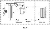
- FIG. 3 is a schematic cycle diagram of a conventional air conditioner during heating operation.
- actual operation temperature points of the heating operation of the air conditioner are generally as follows: from a point A, a high-temperature gaseous refrigerant being 70°C enters an indoor heat exchanger and an indoor environment being 20°C for heat exchange to lower the temperature to 30°C, and enters the throttle device after flowing through an on-line pipe, wherein the temperature (about 30°C) between a point B and the throttle device is much higher than an outdoor environment temperature being 7°C, and afterheat is wasted. If the afterheat is absorbed and used, the degree of supercooling of the system refrigerant cycle can also be increased.
- an air conditioner system provided by the present invention includes a compressor, an indoor heat exchanger, a first throttle device, and an outdoor heat exchanger connected in series in a main circuit.
- the main circuit is also provided with a heat exchanger and a first gas-liquid separator.
- One side of the heat exchanger is connected to a first pipeline between the first throttle device and the indoor heat exchanger, and the other side of the heat exchanger is connected to a second pipeline between the first throttle device and the outdoor heat exchanger.
- a refrigerant passing through the first pipeline and a refrigerant passing through the second pipeline can exchange heat in the heat exchanger.
- the first gas-liquid separator is positioned in a second pipeline section between the heat exchanger and the outdoor heat exchanger.
- a bypass pipeline is disposed between the first gas-liquid separator and the compressor.
- a second throttle device is disposed in the bypass pipeline.
- the second throttle device is configured to control a flow rate of a gaseous refrigerant.
- the first pipeline passes through one side of the heat exchanger, and/or the second pipeline passes through the other side of the heat exchanger.
- a third throttle device is also disposed in the main circuit, and the third throttle device is positioned in a first pipeline section between the heat exchanger and the indoor heat exchanger.
- the third throttle device is in a fully open state, and the first throttle device is configured to throttle the refrigerant.
- the first throttle device is in a fully open state
- the third throttle device is configured to throttle the refrigerant
- the compressor is provided with a second gas-liquid separator, and the refrigerant flows back into the compressor after passing through the second gas-liquid separator.
- bypass pipeline is connected to an upstream of the second gas-liquid separator.
- the air conditioner system also includes a mode switching device.
- the mode switching device is configured to switch the air conditioner system between a refrigeration mode and a heating mode.
- the mode switching device is a four-way valve.
- the heat exchanger is added to the air conditioner system, and the two sides of the heat exchanger are respectively connected to the first pipeline and the second pipeline. Therefore, the refrigerant in the first pipeline and the refrigerant in the second pipeline can exchange heat in the heat exchanger. Not only is the degree of supercooling of the refrigerant in the first pipeline effectively increased, but also the evaporation of the refrigerant in the second pipeline can be promoted, so that a heating capacity of the system is improved.
- bypass pipeline is disposed between the first gas-liquid separator and the compressor, and the gaseous refrigerant passing through the first gas-liquid separator can enter an air suction opening of the compressor through this bypass pipeline, so that the pressure loss of this part of the gaseous refrigerant in a heating cycle is reduced, which is equivalent to that the pressure of the air suction opening of the compressor is increased, the power consumption of the compressor is further reduced, the circulation volume of the refrigerant during the heating cycle of the air conditioner system is increased, and the purpose of improving the heating capacity is achieved.
- the air conditioner of the present invention is also provided with the third throttle device, so that when the air conditioner is switched to the refrigeration mode, the third throttle device is used to replace the first throttle device (at the moment, the first throttle device is in the fully open state) to throttle the refrigerant. Therefore, the occurrence of a phenomenon that a refrigeration capacity is reduced in a refrigeration cycle is avoided.
- Figure 1 is a schematic structure diagram of an embodiment 1 of the present invention.
- the air conditioner system of the present invention includes a compressor 1, an indoor heat exchanger 2, a first throttle device 3, and an outdoor heat exchanger 4 connected in series in a main circuit.
- the main circuit is also provided with a heat exchanger 5.
- a pipeline between the first throttle device 3 and the indoor heat exchanger 2 is used as a first pipeline M
- a pipeline between the first throttle device 3 and the outdoor heat exchanger 4 is used as a second pipeline N.
- One side of the heat exchanger 5 is connected to the first pipeline M, and the other side of the heat exchanger 5 is connected to the second pipeline N.
- the first pipeline M passes through one side of the heat exchanger 5, and the second pipeline N passes through the other side of the heat exchanger N.
- a refrigerant passing through the first pipeline M and a refrigerant passing through the second pipeline N can exchange heat in the heat exchanger 5.
- the main circuit is also provided with a first gas-liquid separator 6.
- the first gas-liquid separator 6 is positioned in a second pipeline N section between the heat exchanger 5 and the outdoor heat exchanger 4, and a bypass pipeline L is disposed between the first gas-liquid separator 6 and the compressor 1.
- a high-temperature high-pressure gaseous refrigerant discharged by the compressor 1 flows to the indoor heat exchanger 2, and exchanges heat in the indoor heat exchanger 2 to become a low-temperature high-pressure liquid refrigerant.
- the refrigerant reaches a point C through the first pipeline M.
- the temperature of the refrigerant is about 20°C (heat here is waste heat which is not sufficiently utilized).
- the refrigerant enters the second pipeline N after being throttled by the first throttle device 3, and at the moment, the temperature of the refrigerant (throttled refrigerant) at a point D is about 5°C.
- the refrigerant in the first pipeline M and the refrigerant in the second pipeline N have temperature differences, and both pass through the heat exchanger 5, so that the refrigerant in the first pipeline M and the refrigerant in the second pipeline N exchange heat in the heat exchanger 5.
- the degree of supercooling of the refrigerant in the first pipeline M effectively increased (i.e., the part of refrigerant from the point C to the first throttle 3 continues to release heat to lower the temperature), but also the evaporation of the refrigerant in the second pipeline N can be promoted (i.e., the low-temperature refrigerant at the point D can perform evaporation heat absorption on afterheat at the point C, which is equivalent to that the evaporation area is increased, and the heat exchange capability is effectively improved), so that a heating capacity is improved.
- the refrigerant exchanging heat through the heat exchanger 5 enters the first gas-liquid separator 6.
- the gaseous refrigerant separated by the first gas-liquid separator 6 directly flows back into the compressor 1 along the bypass pipeline L, so that the pressure loss of this part of the gaseous refrigerant in a heating cycle is reduced, which is equivalent to that the pressure of an air suction opening of the compressor 1 is increased, the power consumption of the compressor 1 is further reduced, the circulation volume of the refrigerant during the heating cycle of the air conditioner system is increased, and the purpose of improving the heating capacity is achieved.
- the liquid refrigerant passing through the first gas-liquid separator 6 flows back into the compressor 1 through the outdoor heat exchanger 4.
- a second throttle device 7 is disposed on the bypass pipeline L.
- the second throttle device 7 is configured to control the flow rate of the gaseous refrigerant, that is, an open degree of the second throttle device 7 may be regulated according to the actual operation work conditions so as to flexibly control the passing quantity of the gaseous refrigerant.
- the second throttle device 7 may be closed, so that the bypass pipeline L does not participate in the refrigeration cycle.
- the above-mentioned heat exchanger 5 may be a water tank containing water or may be in any other suitable form, provided that the refrigerants at the upstream and downstream of the first throttle device 3 can exchange heat. Additionally, the design can effectively improve the heating capacity for the heating cycle and reduce a refrigeration capacity for the refrigeration cycle.
- the air conditioner system of the present invention further includes a mode switching device (e.g., a four-way valve Q in Figure 1 ).
- the mode switching device is configured to switch the air conditioner system between a refrigeration mode and a heating mode.
- FIG. 2 is a schematic structure diagram of an embodiment 2 of the air conditioner system of the present invention.
- a third throttle device 8 is also disposed in the main circuit of the air conditioner system of the present invention.
- the third throttle device 8 is positioned in a first pipeline M section between the heat exchanger 5 and the indoor heat exchanger 2.
- the first throttle device 3 is configured to throttle the refrigerant.
- a principle is identical to that of the air conditioner system in the embodiment 1.
- the first throttle device 3 When the air conditioner system is switched to refrigeration operation through the four-way valve Q, the first throttle device 3 is in a fully open state, the third throttle device 8 is configured to throttle the refrigerant, and meanwhile, the second throttle device 7 is closed.
- the refrigerants at the two sides of the heat exchanger 5 basically have no temperature difference, that is, the heat exchanger 5 does not function in a process of the refrigeration cycle, and the whole refrigeration cycle is a conventional refrigeration cycle. Therefore, the reducing of refrigeration capacity during the refrigeration operation is avoided.
- the compressor 1 is provided with a second gas-liquid separator 11, the gaseous refrigerant entering the compressor 1 firstly passes through the second gas-liquid separator 11 and is then sucked in by the compressor 1, so that a next cycle is started.
- the bypass pipeline L is connected to the upstream of the second gas-liquid separator 11.
- the heat exchanger is added to the air conditioner system of the present invention, and the two sides of the heat exchanger are respectively connected to the first pipeline and the second pipeline. Therefore, the refrigerant in the first pipeline and the refrigerant in the second pipeline can exchange heat in the heat exchanger. Not only is the degree of supercooling of the refrigerant in the first pipeline effectively increased, but also the evaporation of the refrigerant in the second pipeline can be promoted, so that the heating capacity of the system is improved.
- bypass pipeline is disposed between the first gas-liquid separator and the compressor, and the gaseous refrigerant passing through the first gas-liquid separator can enter the air suction opening of the compressor through this bypass pipeline, so that the pressure loss of this part of the gaseous refrigerant in the heating cycle is reduced, which is equivalent to that the pressure of the air suction opening of the compressor is increased, the power consumption of the compressor is further reduced, the circulation volume of the refrigerant during the heating cycle of the air conditioner system is increased, and the purpose of increasing the heating capacity is achieved.
- the air conditioner of the present invention is also provided with the third throttle device, so that when the air conditioner is switched to the refrigeration mode, the third throttle device is used to replace the first throttle device (at the moment, the first throttle device is in the fully open state) to throttle the refrigerant. Therefore, the occurrence of a phenomenon that the refrigeration capacity is reduced in the refrigeration cycle is avoided.
Landscapes
- Engineering & Computer Science (AREA)
- Physics & Mathematics (AREA)
- Mechanical Engineering (AREA)
- Thermal Sciences (AREA)
- General Engineering & Computer Science (AREA)
- Compression-Type Refrigeration Machines With Reversible Cycles (AREA)
Abstract
Description
- The present invention belongs to the technical field of air conditioners, and more particularly relates to an air conditioner system.
- An existing air conditioner system generally uses a condenser, a throttle device, an evaporator and a compressor to form a refrigeration/heating cycle circuit. A high-temperature high-pressure gaseous refrigerant discharged by the compressor is condensed into low-temperature high-pressure liquid in the condenser, is throttled into low-temperature low-pressure liquid through the throttle device, and then enters the evaporator to absorb heat and evaporate to finish a refrigeration/heating cycle.
- During heating operation of the air conditioner, a low-temperature high-pressure liquid refrigerant is formed after the high-temperature high-pressure gaseous refrigerant exchanges heat through the condenser, and then, through throttling and pressure reduction by the throttle device, a low-temperature low-pressure gas-liquid two-phase region refrigerant is formed, and enters the evaporator for heat exchange. The greater the evaporation area is, the higher the relative evaporation capacity is. If the low-temperature high-pressure liquid refrigerant continues to release heat, the degree of supercooling will be increased, so that refrigerating and heating capacities of a system cycle are increased. When the refrigerant is exchanging heat, more than 95% heat exchange quantity comes from a vaporization latent heat quantity in its two-phase region. The isobaric specific heat capacity in a one-phase region (pure liquid or pure gas) is relatively small, and a proportion of the heat exchange quantity in the total system cycle is small. Additionally, the pressure drop of the gaseous refrigerant in a pipeline is great, is a main source of system refrigerant cycle pressure loss, and will increase the cycle work amount, that is, the energy consumption of the system cycle is increased.
- Additionally, referring to
Figure 3, Figure 3 is a schematic cycle diagram of a conventional air conditioner during heating operation. As shown inFigure 3 , actual operation temperature points of the heating operation of the air conditioner are generally as follows: from a point A, a high-temperature gaseous refrigerant being 70°C enters an indoor heat exchanger and an indoor environment being 20°C for heat exchange to lower the temperature to 30°C, and enters the throttle device after flowing through an on-line pipe, wherein the temperature (about 30°C) between a point B and the throttle device is much higher than an outdoor environment temperature being 7°C, and afterheat is wasted. If the afterheat is absorbed and used, the degree of supercooling of the system refrigerant cycle can also be increased. - Based on the above, the present invention is provided.
- In order to solve the problems in the prior art, i.e., in order to improve a heating cycle effect of an air conditioner, an air conditioner system provided by the present invention includes a compressor, an indoor heat exchanger, a first throttle device, and an outdoor heat exchanger connected in series in a main circuit. The main circuit is also provided with a heat exchanger and a first gas-liquid separator. One side of the heat exchanger is connected to a first pipeline between the first throttle device and the indoor heat exchanger, and the other side of the heat exchanger is connected to a second pipeline between the first throttle device and the outdoor heat exchanger. A refrigerant passing through the first pipeline and a refrigerant passing through the second pipeline can exchange heat in the heat exchanger. The first gas-liquid separator is positioned in a second pipeline section between the heat exchanger and the outdoor heat exchanger. A bypass pipeline is disposed between the first gas-liquid separator and the compressor.
- In an exemplary implementation of the air conditioner system, a second throttle device is disposed in the bypass pipeline. During heating operation of the air conditioner system, the second throttle device is configured to control a flow rate of a gaseous refrigerant.
- In an exemplary implementation of the air conditioner system, the first pipeline passes through one side of the heat exchanger, and/or the second pipeline passes through the other side of the heat exchanger.
- In an exemplary implementation of the air conditioner system, a third throttle device is also disposed in the main circuit, and the third throttle device is positioned in a first pipeline section between the heat exchanger and the indoor heat exchanger.
- In an exemplary implementation of the air conditioner system, during heating operation of the air conditioner system, the third throttle device is in a fully open state, and the first throttle device is configured to throttle the refrigerant.
- In an exemplary implementation of the air conditioner system, during refrigeration operation of the air conditioner system, the first throttle device is in a fully open state, and the third throttle device is configured to throttle the refrigerant.
- In an exemplary implementation of the air conditioner system, the compressor is provided with a second gas-liquid separator, and the refrigerant flows back into the compressor after passing through the second gas-liquid separator.
- In an exemplary implementation of the air conditioner system, the bypass pipeline is connected to an upstream of the second gas-liquid separator.
- In an exemplary implementation of the air conditioner system, the air conditioner system also includes a mode switching device. The mode switching device is configured to switch the air conditioner system between a refrigeration mode and a heating mode.
- In an exemplary implementation of the air conditioner system, the mode switching device is a four-way valve.
- In the technical schemes of the present invention, the heat exchanger is added to the air conditioner system, and the two sides of the heat exchanger are respectively connected to the first pipeline and the second pipeline. Therefore, the refrigerant in the first pipeline and the refrigerant in the second pipeline can exchange heat in the heat exchanger. Not only is the degree of supercooling of the refrigerant in the first pipeline effectively increased, but also the evaporation of the refrigerant in the second pipeline can be promoted, so that a heating capacity of the system is improved. In addition, the bypass pipeline is disposed between the first gas-liquid separator and the compressor, and the gaseous refrigerant passing through the first gas-liquid separator can enter an air suction opening of the compressor through this bypass pipeline, so that the pressure loss of this part of the gaseous refrigerant in a heating cycle is reduced, which is equivalent to that the pressure of the air suction opening of the compressor is increased, the power consumption of the compressor is further reduced, the circulation volume of the refrigerant during the heating cycle of the air conditioner system is increased, and the purpose of improving the heating capacity is achieved. Additionally, the air conditioner of the present invention is also provided with the third throttle device, so that when the air conditioner is switched to the refrigeration mode, the third throttle device is used to replace the first throttle device (at the moment, the first throttle device is in the fully open state) to throttle the refrigerant. Therefore, the occurrence of a phenomenon that a refrigeration capacity is reduced in a refrigeration cycle is avoided.
-
-
Figure 1 is a schematic structure diagram of anembodiment 1 of an air conditioner system of the present invention. -
Figure 2 is a schematic structure diagram of anembodiment 2 of the air conditioner system of the present invention. -
Figure 3 is a schematic cycle diagram of a conventional air conditioner during heating operation. - For the purpose of making embodiments, technical schemes and advantages of the present invention more clear, clear and complete description will be made to the technical schemes of the present invention in conjunction with drawings. Obviously, the described embodiments are merely a part of the embodiments of the present invention and not all the embodiments. It should be understood by those skilled in the art that these implementations are merely intended to explain the technical principles of the present invention and are not intended to limit the protection scope of the present invention.
- Firstly, referring to
Figure 1, Figure 1 is a schematic structure diagram of anembodiment 1 of the present invention. As shown inFigure 1 , the air conditioner system of the present invention includes acompressor 1, anindoor heat exchanger 2, afirst throttle device 3, and anoutdoor heat exchanger 4 connected in series in a main circuit. The main circuit is also provided with aheat exchanger 5. For illustration purposes, a pipeline between thefirst throttle device 3 and theindoor heat exchanger 2 is used as a first pipeline M, and a pipeline between thefirst throttle device 3 and theoutdoor heat exchanger 4 is used as a second pipeline N. One side of theheat exchanger 5 is connected to the first pipeline M, and the other side of theheat exchanger 5 is connected to the second pipeline N. According to a connection mode as shown inFigure 1 , the first pipeline M passes through one side of theheat exchanger 5, and the second pipeline N passes through the other side of the heat exchanger N. In addition, a refrigerant passing through the first pipeline M and a refrigerant passing through the second pipeline N can exchange heat in theheat exchanger 5. Additionally, the main circuit is also provided with a first gas-liquid separator 6. The first gas-liquid separator 6 is positioned in a second pipeline N section between theheat exchanger 5 and theoutdoor heat exchanger 4, and a bypass pipeline L is disposed between the first gas-liquid separator 6 and thecompressor 1. - In the heating cycle process of the air conditioner, a high-temperature high-pressure gaseous refrigerant discharged by the
compressor 1 flows to theindoor heat exchanger 2, and exchanges heat in theindoor heat exchanger 2 to become a low-temperature high-pressure liquid refrigerant. The refrigerant reaches a point C through the first pipeline M. At the moment, the temperature of the refrigerant is about 20°C (heat here is waste heat which is not sufficiently utilized). Then, the refrigerant enters the second pipeline N after being throttled by thefirst throttle device 3, and at the moment, the temperature of the refrigerant (throttled refrigerant) at a point D is about 5°C. The refrigerant in the first pipeline M and the refrigerant in the second pipeline N have temperature differences, and both pass through theheat exchanger 5, so that the refrigerant in the first pipeline M and the refrigerant in the second pipeline N exchange heat in theheat exchanger 5. Not only is the degree of supercooling of the refrigerant in the first pipeline M effectively increased (i.e., the part of refrigerant from the point C to thefirst throttle 3 continues to release heat to lower the temperature), but also the evaporation of the refrigerant in the second pipeline N can be promoted (i.e., the low-temperature refrigerant at the point D can perform evaporation heat absorption on afterheat at the point C, which is equivalent to that the evaporation area is increased, and the heat exchange capability is effectively improved), so that a heating capacity is improved. - Then, the refrigerant exchanging heat through the
heat exchanger 5 enters the first gas-liquid separator 6. The gaseous refrigerant separated by the first gas-liquid separator 6 directly flows back into thecompressor 1 along the bypass pipeline L, so that the pressure loss of this part of the gaseous refrigerant in a heating cycle is reduced, which is equivalent to that the pressure of an air suction opening of thecompressor 1 is increased, the power consumption of thecompressor 1 is further reduced, the circulation volume of the refrigerant during the heating cycle of the air conditioner system is increased, and the purpose of improving the heating capacity is achieved. The liquid refrigerant passing through the first gas-liquid separator 6 flows back into thecompressor 1 through theoutdoor heat exchanger 4. Through the design, in a heating operation process of the air conditioner, not only can the waste heat be reused, but also the power consumption of the system may be reduced, and the circulation volume of the refrigerant during the heating cycle of the air conditioner system is increased, so that the heating capacity of the whole system is improved. - As an example, a
second throttle device 7 is disposed on the bypass pipeline L. During heating operation of the air conditioner, thesecond throttle device 7 is configured to control the flow rate of the gaseous refrigerant, that is, an open degree of thesecond throttle device 7 may be regulated according to the actual operation work conditions so as to flexibly control the passing quantity of the gaseous refrigerant. During a refrigeration cycle of the air conditioner, thesecond throttle device 7 may be closed, so that the bypass pipeline L does not participate in the refrigeration cycle. - It should be noted that the above-mentioned
heat exchanger 5 may be a water tank containing water or may be in any other suitable form, provided that the refrigerants at the upstream and downstream of thefirst throttle device 3 can exchange heat. Additionally, the design can effectively improve the heating capacity for the heating cycle and reduce a refrigeration capacity for the refrigeration cycle. - As an example, the air conditioner system of the present invention further includes a mode switching device (e.g., a four-way valve Q in
Figure 1 ). The mode switching device is configured to switch the air conditioner system between a refrigeration mode and a heating mode. - As an example, referring to
Figure 2, Figure 2 is a schematic structure diagram of anembodiment 2 of the air conditioner system of the present invention. As shown inFigure 2 , athird throttle device 8 is also disposed in the main circuit of the air conditioner system of the present invention. Thethird throttle device 8 is positioned in a first pipeline M section between theheat exchanger 5 and theindoor heat exchanger 2. During the heating operation of the air conditioner, thethird throttle device 8 is in a fully open state. Thefirst throttle device 3 is configured to throttle the refrigerant. At the moment, a principle is identical to that of the air conditioner system in theembodiment 1. When the air conditioner system is switched to refrigeration operation through the four-way valve Q, thefirst throttle device 3 is in a fully open state, thethird throttle device 8 is configured to throttle the refrigerant, and meanwhile, thesecond throttle device 7 is closed. At the moment, the refrigerants at the two sides of theheat exchanger 5 basically have no temperature difference, that is, theheat exchanger 5 does not function in a process of the refrigeration cycle, and the whole refrigeration cycle is a conventional refrigeration cycle. Therefore, the reducing of refrigeration capacity during the refrigeration operation is avoided. - Preferably, referring to
Figure 1 and Figure 2 , thecompressor 1 is provided with a second gas-liquid separator 11, the gaseous refrigerant entering thecompressor 1 firstly passes through the second gas-liquid separator 11 and is then sucked in by thecompressor 1, so that a next cycle is started. The bypass pipeline L is connected to the upstream of the second gas-liquid separator 11. - Based on the above, the heat exchanger is added to the air conditioner system of the present invention, and the two sides of the heat exchanger are respectively connected to the first pipeline and the second pipeline. Therefore, the refrigerant in the first pipeline and the refrigerant in the second pipeline can exchange heat in the heat exchanger. Not only is the degree of supercooling of the refrigerant in the first pipeline effectively increased, but also the evaporation of the refrigerant in the second pipeline can be promoted, so that the heating capacity of the system is improved. In addition, the bypass pipeline is disposed between the first gas-liquid separator and the compressor, and the gaseous refrigerant passing through the first gas-liquid separator can enter the air suction opening of the compressor through this bypass pipeline, so that the pressure loss of this part of the gaseous refrigerant in the heating cycle is reduced, which is equivalent to that the pressure of the air suction opening of the compressor is increased, the power consumption of the compressor is further reduced, the circulation volume of the refrigerant during the heating cycle of the air conditioner system is increased, and the purpose of increasing the heating capacity is achieved. Additionally, the air conditioner of the present invention is also provided with the third throttle device, so that when the air conditioner is switched to the refrigeration mode, the third throttle device is used to replace the first throttle device (at the moment, the first throttle device is in the fully open state) to throttle the refrigerant. Therefore, the occurrence of a phenomenon that the refrigeration capacity is reduced in the refrigeration cycle is avoided.
- So far, the technical schemes of the present invention have been described in conjunction with the exemplary implementations shown in the drawings, but it will be readily understood by those skilled in the art that the protection scope of the present invention is obviously not limited to these specific implementations. Those skilled in the art can make equivalent alterations or substitutions to the relevant technical features without departing from the principles of the present invention, and the technical schemes after these alterations or substitutions will all fall within the protection scope of the present invention.
Claims (10)
- An air conditioner system, comprising a compressor, an indoor heat exchanger, a first throttle device, and an outdoor heat exchanger connected in series in a main circuit,
wherein the main circuit is also provided with a heat exchanger and a first gas-liquid separator;
one side of the heat exchanger is connected to a first pipeline between the first throttle device and the indoor heat exchanger, and the other side of the heat exchanger is connected to a second pipeline between the first throttle device and the outdoor heat exchanger, so that a refrigerant passing through the first pipeline and a refrigerant passing through the second pipeline can exchange heat in the heat exchanger; and
the first gas-liquid separator is positioned in a second pipeline section between the heat exchanger and the outdoor heat exchanger, and a bypass pipeline is disposed between the first gas-liquid separator and the compressor. - The air conditioner system according to claim 1, wherein a second throttle device is disposed in the bypass pipeline, and during heating operation of the air conditioner system, the second throttle device is configured to control a flow rate of a gaseous refrigerant.
- The air conditioner system according to claim 1, wherein the first pipeline passes through one side of the heat exchanger, and/or the second pipeline passes through the other side of the heat exchanger.
- The air conditioner system according to claim 3, wherein a third throttle device is also disposed in the main circuit, and the third throttle device is positioned in a first pipeline section between the heat exchanger and the indoor heat exchanger.
- The air conditioner system according to claim 4, wherein during heating operation of the air conditioner system, the third throttle device is in a fully open state, and the first throttle device is configured to throttle the refrigerant.
- The air conditioner system according to claim 4, wherein during refrigeration operation of the air conditioner system, the first throttle device is in a fully open state, and the third throttle device is configured to throttle the refrigerant.
- The air conditioner system according to any one of claims 1 to 6, wherein the compressor is provided with a second gas-liquid separator, and the refrigerant flows back into the compressor after passing through the second gas-liquid separator.
- The air conditioner system according to claim 7, wherein the bypass pipeline is connected to an upstream of the second gas-liquid separator.
- The air conditioner system according to any one of claims 1 to 6, wherein the air conditioner system also comprises a mode switching device, and the mode switching device is configured to switch the air conditioner system between a refrigeration mode and a heating mode.
- The air conditioner system according to claim 9, wherein the mode switching device is a four-way valve.
Applications Claiming Priority (2)
| Application Number | Priority Date | Filing Date | Title |
|---|---|---|---|
| CN201711471669.9A CN108375255B (en) | 2017-12-29 | 2017-12-29 | Air conditioner system |
| PCT/CN2018/115748 WO2019128517A1 (en) | 2017-12-29 | 2018-11-15 | Air-conditioner system |
Publications (3)
| Publication Number | Publication Date |
|---|---|
| EP3734199A1 true EP3734199A1 (en) | 2020-11-04 |
| EP3734199A4 EP3734199A4 (en) | 2021-02-24 |
| EP3734199B1 EP3734199B1 (en) | 2022-07-27 |
Family
ID=63015488
Family Applications (1)
| Application Number | Title | Priority Date | Filing Date |
|---|---|---|---|
| EP18894319.5A Active EP3734199B1 (en) | 2017-12-29 | 2018-11-15 | Air-conditioner system |
Country Status (4)
| Country | Link |
|---|---|
| EP (1) | EP3734199B1 (en) |
| JP (1) | JP6982692B2 (en) |
| CN (1) | CN108375255B (en) |
| WO (1) | WO2019128517A1 (en) |
Families Citing this family (2)
| Publication number | Priority date | Publication date | Assignee | Title |
|---|---|---|---|---|
| CN108375255B (en) * | 2017-12-29 | 2019-12-06 | 青岛海尔空调器有限总公司 | Air conditioner system |
| CN111059615A (en) * | 2019-12-20 | 2020-04-24 | 青岛海尔空调电子有限公司 | Multi-line air conditioning system |
Family Cites Families (20)
| Publication number | Priority date | Publication date | Assignee | Title |
|---|---|---|---|---|
| EP1526345B1 (en) * | 2002-08-02 | 2010-11-24 | Daikin Industries, Ltd. | Refrigeration equipment |
| JPWO2009087733A1 (en) * | 2008-01-07 | 2011-05-19 | 三菱電機株式会社 | Refrigeration cycle equipment and four-way valve |
| CN101776308B (en) * | 2009-01-13 | 2012-11-21 | 珠海格力电器股份有限公司 | Energy-saving air conditioner |
| JP5452138B2 (en) * | 2009-09-01 | 2014-03-26 | 三菱電機株式会社 | Refrigeration air conditioner |
| JP5278452B2 (en) * | 2011-01-27 | 2013-09-04 | パナソニック株式会社 | Refrigeration cycle apparatus and hot water heater using the same |
| JP2013204952A (en) * | 2012-03-29 | 2013-10-07 | Fujitsu General Ltd | Refrigeration cycle device |
| CN203132222U (en) * | 2013-01-23 | 2013-08-14 | 广东美的制冷设备有限公司 | Air-conditioner system |
| WO2014129361A1 (en) * | 2013-02-19 | 2014-08-28 | 三菱電機株式会社 | Air conditioner |
| CN203432134U (en) * | 2013-07-05 | 2014-02-12 | 广东长菱空调冷气机制造有限公司 | Heat pump system of air source heat pump water heater |
| US8763424B1 (en) * | 2013-09-30 | 2014-07-01 | Heat Pump Technologies, LLC | Subcooling heat exchanger adapted for evaporator distribution lines in a refrigeration circuit |
| CN107076467B (en) * | 2014-11-04 | 2020-01-17 | 三菱电机株式会社 | Air conditioning device |
| JP6304407B2 (en) * | 2015-02-04 | 2018-04-04 | 株式会社デンソー | Integrated valve and heat pump cycle |
| WO2016135935A1 (en) * | 2015-02-27 | 2016-09-01 | ジョンソンコントロールズ ヒタチ エア コンディショニング テクノロジー(ホンコン)リミテッド | Heat exchange apparatus and air conditioner using same |
| CN106016535B (en) * | 2016-05-31 | 2019-01-08 | 广东美的制冷设备有限公司 | Air injection enthalpy-increasing air-conditioning system and its defrosting control method |
| CN106016505B (en) * | 2016-06-12 | 2019-05-31 | 青岛海尔空调器有限总公司 | Air conditioner circuit board cooling device |
| CN106403347B (en) * | 2016-11-22 | 2019-01-29 | 广东美的暖通设备有限公司 | Low temperature air conditioning systems and air conditioners |
| CN206310607U (en) * | 2016-11-30 | 2017-07-07 | 美的集团股份有限公司 | A kind of control system and air-conditioner for improving air-conditioning heating effect |
| CN107084562A (en) * | 2017-04-13 | 2017-08-22 | 青岛海尔空调器有限总公司 | A kind of control method of air conditioner and air conditioner |
| CN206739693U (en) * | 2017-04-24 | 2017-12-12 | 深圳创维空调科技有限公司 | A kind of air-conditioner system |
| CN108375255B (en) * | 2017-12-29 | 2019-12-06 | 青岛海尔空调器有限总公司 | Air conditioner system |
-
2017
- 2017-12-29 CN CN201711471669.9A patent/CN108375255B/en active Active
-
2018
- 2018-11-15 EP EP18894319.5A patent/EP3734199B1/en active Active
- 2018-11-15 WO PCT/CN2018/115748 patent/WO2019128517A1/en not_active Ceased
- 2018-11-15 JP JP2020535567A patent/JP6982692B2/en active Active
Also Published As
| Publication number | Publication date |
|---|---|
| WO2019128517A1 (en) | 2019-07-04 |
| CN108375255B (en) | 2019-12-06 |
| EP3734199B1 (en) | 2022-07-27 |
| JP2021508025A (en) | 2021-02-25 |
| EP3734199A4 (en) | 2021-02-24 |
| JP6982692B2 (en) | 2021-12-17 |
| CN108375255A (en) | 2018-08-07 |
Similar Documents
| Publication | Publication Date | Title |
|---|---|---|
| EP3734167B1 (en) | Air conditioner system | |
| WO2019091241A1 (en) | Cooling circulation system for air conditioning, and air conditioner | |
| CN107178833B (en) | Heat recovery external machine system and air conditioning system | |
| CN101776308B (en) | Energy-saving air conditioner | |
| WO2019091240A1 (en) | Heating circulation system for air conditioning, and air conditioner | |
| CN108759142B (en) | Special cascade air source high-temperature heat pump cooling and heating system | |
| EP3734193A1 (en) | Air conditioner system | |
| CN213272814U (en) | Multi-connected air conditioning system | |
| CN106500378A (en) | Based on the efficient air conditioning unit and control method that high temperature refrigerant mixes again heat pattern | |
| EP3734199A1 (en) | Air-conditioner system | |
| CN107477900A (en) | Air conditioner circulating system and round-robin method and air-conditioning | |
| CN110654199A (en) | New energy automobile heat pump air conditioning system with ejector | |
| CN106766332A (en) | Air conditioning system unit and air conditioning system | |
| EP3734192B1 (en) | Air conditioner system | |
| CN207702631U (en) | Air conditioner cooling cycle system and air conditioner | |
| CN108131803A (en) | The control method of multi-gang air-conditioner | |
| CN109611992B (en) | Heat recovery type multi-split air conditioner system with multiple operation modes and control method | |
| CN206514563U (en) | Air conditioning system unit and air conditioning system | |
| CN214249789U (en) | Multi-split air conditioner | |
| CN102914089B (en) | Multi-branch outdoor heat exchanger with synchronous heat exchange function | |
| CN206274212U (en) | Air conditioner circulating system and air-conditioning | |
| CN222925599U (en) | High-efficient low temperature dehumidification heat pump system | |
| CN221611613U (en) | Heat exchanger with supercooling pipeline and air conditioner | |
| CN207778854U (en) | The air-conditioning heating circulatory system and air conditioner | |
| EP4008973B1 (en) | Air conditioner |
Legal Events
| Date | Code | Title | Description |
|---|---|---|---|
| STAA | Information on the status of an ep patent application or granted ep patent |
Free format text: STATUS: THE INTERNATIONAL PUBLICATION HAS BEEN MADE |
|
| PUAI | Public reference made under article 153(3) epc to a published international application that has entered the european phase |
Free format text: ORIGINAL CODE: 0009012 |
|
| STAA | Information on the status of an ep patent application or granted ep patent |
Free format text: STATUS: REQUEST FOR EXAMINATION WAS MADE |
|
| 17P | Request for examination filed |
Effective date: 20200727 |
|
| AK | Designated contracting states |
Kind code of ref document: A1 Designated state(s): AL AT BE BG CH CY CZ DE DK EE ES FI FR GB GR HR HU IE IS IT LI LT LU LV MC MK MT NL NO PL PT RO RS SE SI SK SM TR |
|
| AX | Request for extension of the european patent |
Extension state: BA ME |
|
| STAA | Information on the status of an ep patent application or granted ep patent |
Free format text: STATUS: EXAMINATION IS IN PROGRESS |
|
| A4 | Supplementary search report drawn up and despatched |
Effective date: 20210121 |
|
| RIC1 | Information provided on ipc code assigned before grant |
Ipc: F25B 40/02 20060101ALI20210115BHEP Ipc: F25B 47/02 20060101AFI20210115BHEP Ipc: F25B 41/00 20210101ALI20210115BHEP Ipc: F25B 40/00 20060101ALI20210115BHEP Ipc: F25B 13/00 20060101ALI20210115BHEP |
|
| 17Q | First examination report despatched |
Effective date: 20210202 |
|
| DAV | Request for validation of the european patent (deleted) | ||
| DAX | Request for extension of the european patent (deleted) | ||
| RAP1 | Party data changed (applicant data changed or rights of an application transferred) |
Owner name: QINGDAO HAIER AIR CONDITIONER GENERAL CORP., LTD. Owner name: CHONGQING HAIER AIR CONDITIONER CO., LTD |
|
| GRAP | Despatch of communication of intention to grant a patent |
Free format text: ORIGINAL CODE: EPIDOSNIGR1 |
|
| STAA | Information on the status of an ep patent application or granted ep patent |
Free format text: STATUS: GRANT OF PATENT IS INTENDED |
|
| INTG | Intention to grant announced |
Effective date: 20220511 |
|
| RIN1 | Information on inventor provided before grant (corrected) |
Inventor name: XU, WENMING Inventor name: LUO, RONGBANG Inventor name: FU, YU Inventor name: WANG, FEI |
|
| GRAS | Grant fee paid |
Free format text: ORIGINAL CODE: EPIDOSNIGR3 |
|
| GRAA | (expected) grant |
Free format text: ORIGINAL CODE: 0009210 |
|
| STAA | Information on the status of an ep patent application or granted ep patent |
Free format text: STATUS: THE PATENT HAS BEEN GRANTED |
|
| AK | Designated contracting states |
Kind code of ref document: B1 Designated state(s): AL AT BE BG CH CY CZ DE DK EE ES FI FR GB GR HR HU IE IS IT LI LT LU LV MC MK MT NL NO PL PT RO RS SE SI SK SM TR |
|
| REG | Reference to a national code |
Ref country code: CH Ref legal event code: EP |
|
| REG | Reference to a national code |
Ref country code: AT Ref legal event code: REF Ref document number: 1507306 Country of ref document: AT Kind code of ref document: T Effective date: 20220815 |
|
| REG | Reference to a national code |
Ref country code: DE Ref legal event code: R096 Ref document number: 602018038606 Country of ref document: DE |
|
| REG | Reference to a national code |
Ref country code: IE Ref legal event code: FG4D |
|
| REG | Reference to a national code |
Ref country code: SE Ref legal event code: TRGR |
|
| REG | Reference to a national code |
Ref country code: NO Ref legal event code: T2 Effective date: 20220727 |
|
| REG | Reference to a national code |
Ref country code: LT Ref legal event code: MG9D |
|
| REG | Reference to a national code |
Ref country code: NL Ref legal event code: MP Effective date: 20220727 |
|
| PG25 | Lapsed in a contracting state [announced via postgrant information from national office to epo] |
Ref country code: RS Free format text: LAPSE BECAUSE OF FAILURE TO SUBMIT A TRANSLATION OF THE DESCRIPTION OR TO PAY THE FEE WITHIN THE PRESCRIBED TIME-LIMIT Effective date: 20220727 Ref country code: PT Free format text: LAPSE BECAUSE OF FAILURE TO SUBMIT A TRANSLATION OF THE DESCRIPTION OR TO PAY THE FEE WITHIN THE PRESCRIBED TIME-LIMIT Effective date: 20221128 Ref country code: NL Free format text: LAPSE BECAUSE OF FAILURE TO SUBMIT A TRANSLATION OF THE DESCRIPTION OR TO PAY THE FEE WITHIN THE PRESCRIBED TIME-LIMIT Effective date: 20220727 Ref country code: LV Free format text: LAPSE BECAUSE OF FAILURE TO SUBMIT A TRANSLATION OF THE DESCRIPTION OR TO PAY THE FEE WITHIN THE PRESCRIBED TIME-LIMIT Effective date: 20220727 Ref country code: LT Free format text: LAPSE BECAUSE OF FAILURE TO SUBMIT A TRANSLATION OF THE DESCRIPTION OR TO PAY THE FEE WITHIN THE PRESCRIBED TIME-LIMIT Effective date: 20220727 Ref country code: FI Free format text: LAPSE BECAUSE OF FAILURE TO SUBMIT A TRANSLATION OF THE DESCRIPTION OR TO PAY THE FEE WITHIN THE PRESCRIBED TIME-LIMIT Effective date: 20220727 Ref country code: ES Free format text: LAPSE BECAUSE OF FAILURE TO SUBMIT A TRANSLATION OF THE DESCRIPTION OR TO PAY THE FEE WITHIN THE PRESCRIBED TIME-LIMIT Effective date: 20220727 |
|
| PG25 | Lapsed in a contracting state [announced via postgrant information from national office to epo] |
Ref country code: PL Free format text: LAPSE BECAUSE OF FAILURE TO SUBMIT A TRANSLATION OF THE DESCRIPTION OR TO PAY THE FEE WITHIN THE PRESCRIBED TIME-LIMIT Effective date: 20220727 Ref country code: IS Free format text: LAPSE BECAUSE OF FAILURE TO SUBMIT A TRANSLATION OF THE DESCRIPTION OR TO PAY THE FEE WITHIN THE PRESCRIBED TIME-LIMIT Effective date: 20221127 Ref country code: HR Free format text: LAPSE BECAUSE OF FAILURE TO SUBMIT A TRANSLATION OF THE DESCRIPTION OR TO PAY THE FEE WITHIN THE PRESCRIBED TIME-LIMIT Effective date: 20220727 Ref country code: GR Free format text: LAPSE BECAUSE OF FAILURE TO SUBMIT A TRANSLATION OF THE DESCRIPTION OR TO PAY THE FEE WITHIN THE PRESCRIBED TIME-LIMIT Effective date: 20221028 |
|
| PG25 | Lapsed in a contracting state [announced via postgrant information from national office to epo] |
Ref country code: SM Free format text: LAPSE BECAUSE OF FAILURE TO SUBMIT A TRANSLATION OF THE DESCRIPTION OR TO PAY THE FEE WITHIN THE PRESCRIBED TIME-LIMIT Effective date: 20220727 Ref country code: RO Free format text: LAPSE BECAUSE OF FAILURE TO SUBMIT A TRANSLATION OF THE DESCRIPTION OR TO PAY THE FEE WITHIN THE PRESCRIBED TIME-LIMIT Effective date: 20220727 Ref country code: DK Free format text: LAPSE BECAUSE OF FAILURE TO SUBMIT A TRANSLATION OF THE DESCRIPTION OR TO PAY THE FEE WITHIN THE PRESCRIBED TIME-LIMIT Effective date: 20220727 Ref country code: CZ Free format text: LAPSE BECAUSE OF FAILURE TO SUBMIT A TRANSLATION OF THE DESCRIPTION OR TO PAY THE FEE WITHIN THE PRESCRIBED TIME-LIMIT Effective date: 20220727 |
|
| REG | Reference to a national code |
Ref country code: DE Ref legal event code: R097 Ref document number: 602018038606 Country of ref document: DE |
|
| PG25 | Lapsed in a contracting state [announced via postgrant information from national office to epo] |
Ref country code: SK Free format text: LAPSE BECAUSE OF FAILURE TO SUBMIT A TRANSLATION OF THE DESCRIPTION OR TO PAY THE FEE WITHIN THE PRESCRIBED TIME-LIMIT Effective date: 20220727 Ref country code: EE Free format text: LAPSE BECAUSE OF FAILURE TO SUBMIT A TRANSLATION OF THE DESCRIPTION OR TO PAY THE FEE WITHIN THE PRESCRIBED TIME-LIMIT Effective date: 20220727 |
|
| PLBE | No opposition filed within time limit |
Free format text: ORIGINAL CODE: 0009261 |
|
| STAA | Information on the status of an ep patent application or granted ep patent |
Free format text: STATUS: NO OPPOSITION FILED WITHIN TIME LIMIT |
|
| PG25 | Lapsed in a contracting state [announced via postgrant information from national office to epo] |
Ref country code: MC Free format text: LAPSE BECAUSE OF FAILURE TO SUBMIT A TRANSLATION OF THE DESCRIPTION OR TO PAY THE FEE WITHIN THE PRESCRIBED TIME-LIMIT Effective date: 20220727 Ref country code: AL Free format text: LAPSE BECAUSE OF FAILURE TO SUBMIT A TRANSLATION OF THE DESCRIPTION OR TO PAY THE FEE WITHIN THE PRESCRIBED TIME-LIMIT Effective date: 20220727 |
|
| 26N | No opposition filed |
Effective date: 20230502 |
|
| PG25 | Lapsed in a contracting state [announced via postgrant information from national office to epo] |
Ref country code: SI Free format text: LAPSE BECAUSE OF FAILURE TO SUBMIT A TRANSLATION OF THE DESCRIPTION OR TO PAY THE FEE WITHIN THE PRESCRIBED TIME-LIMIT Effective date: 20220727 Ref country code: LU Free format text: LAPSE BECAUSE OF NON-PAYMENT OF DUE FEES Effective date: 20221115 |
|
| PG25 | Lapsed in a contracting state [announced via postgrant information from national office to epo] |
Ref country code: IT Free format text: LAPSE BECAUSE OF NON-PAYMENT OF DUE FEES Effective date: 20221115 Ref country code: IE Free format text: LAPSE BECAUSE OF NON-PAYMENT OF DUE FEES Effective date: 20221115 |
|
| REG | Reference to a national code |
Ref country code: AT Ref legal event code: UEP Ref document number: 1507306 Country of ref document: AT Kind code of ref document: T Effective date: 20220727 |
|
| PG25 | Lapsed in a contracting state [announced via postgrant information from national office to epo] |
Ref country code: CY Free format text: LAPSE BECAUSE OF FAILURE TO SUBMIT A TRANSLATION OF THE DESCRIPTION OR TO PAY THE FEE WITHIN THE PRESCRIBED TIME-LIMIT Effective date: 20220727 |
|
| PG25 | Lapsed in a contracting state [announced via postgrant information from national office to epo] |
Ref country code: MK Free format text: LAPSE BECAUSE OF FAILURE TO SUBMIT A TRANSLATION OF THE DESCRIPTION OR TO PAY THE FEE WITHIN THE PRESCRIBED TIME-LIMIT Effective date: 20220727 Ref country code: HU Free format text: LAPSE BECAUSE OF FAILURE TO SUBMIT A TRANSLATION OF THE DESCRIPTION OR TO PAY THE FEE WITHIN THE PRESCRIBED TIME-LIMIT; INVALID AB INITIO Effective date: 20181115 |
|
| PG25 | Lapsed in a contracting state [announced via postgrant information from national office to epo] |
Ref country code: BG Free format text: LAPSE BECAUSE OF FAILURE TO SUBMIT A TRANSLATION OF THE DESCRIPTION OR TO PAY THE FEE WITHIN THE PRESCRIBED TIME-LIMIT Effective date: 20220727 |
|
| PG25 | Lapsed in a contracting state [announced via postgrant information from national office to epo] |
Ref country code: MT Free format text: LAPSE BECAUSE OF FAILURE TO SUBMIT A TRANSLATION OF THE DESCRIPTION OR TO PAY THE FEE WITHIN THE PRESCRIBED TIME-LIMIT Effective date: 20220727 |
|
| REG | Reference to a national code |
Ref country code: CH Ref legal event code: U11 Free format text: ST27 STATUS EVENT CODE: U-0-0-U10-U11 (AS PROVIDED BY THE NATIONAL OFFICE) Effective date: 20251201 |
|
| PG25 | Lapsed in a contracting state [announced via postgrant information from national office to epo] |
Ref country code: TR Free format text: LAPSE BECAUSE OF FAILURE TO SUBMIT A TRANSLATION OF THE DESCRIPTION OR TO PAY THE FEE WITHIN THE PRESCRIBED TIME-LIMIT Effective date: 20220727 |
|
| PGFP | Annual fee paid to national office [announced via postgrant information from national office to epo] |
Ref country code: DE Payment date: 20251117 Year of fee payment: 8 |
|
| PGFP | Annual fee paid to national office [announced via postgrant information from national office to epo] |
Ref country code: GB Payment date: 20251126 Year of fee payment: 8 |
|
| PGFP | Annual fee paid to national office [announced via postgrant information from national office to epo] |
Ref country code: NO Payment date: 20251028 Year of fee payment: 8 |
|
| PGFP | Annual fee paid to national office [announced via postgrant information from national office to epo] |
Ref country code: AT Payment date: 20251024 Year of fee payment: 8 |
|
| PGFP | Annual fee paid to national office [announced via postgrant information from national office to epo] |
Ref country code: FR Payment date: 20251127 Year of fee payment: 8 |
|
| PGFP | Annual fee paid to national office [announced via postgrant information from national office to epo] |
Ref country code: BE Payment date: 20251120 Year of fee payment: 8 |
|
| PGFP | Annual fee paid to national office [announced via postgrant information from national office to epo] |
Ref country code: SE Payment date: 20251121 Year of fee payment: 8 Ref country code: CH Payment date: 20251201 Year of fee payment: 8 |