EP3734131A1 - Loading arm connector and loading arm - Google Patents
Loading arm connector and loading arm Download PDFInfo
- Publication number
- EP3734131A1 EP3734131A1 EP18896842.4A EP18896842A EP3734131A1 EP 3734131 A1 EP3734131 A1 EP 3734131A1 EP 18896842 A EP18896842 A EP 18896842A EP 3734131 A1 EP3734131 A1 EP 3734131A1
- Authority
- EP
- European Patent Office
- Prior art keywords
- pipe
- insulator
- flange
- blocking member
- fluid loading
- Prior art date
- Legal status (The legal status is an assumption and is not a legal conclusion. Google has not performed a legal analysis and makes no representation as to the accuracy of the status listed.)
- Granted
Links
Images



Classifications
-
- B—PERFORMING OPERATIONS; TRANSPORTING
- B67—OPENING, CLOSING OR CLEANING BOTTLES, JARS OR SIMILAR CONTAINERS; LIQUID HANDLING
- B67D—DISPENSING, DELIVERING OR TRANSFERRING LIQUIDS, NOT OTHERWISE PROVIDED FOR
- B67D9/00—Apparatus or devices for transferring liquids when loading or unloading ships
- B67D9/02—Apparatus or devices for transferring liquids when loading or unloading ships using articulated pipes
-
- F—MECHANICAL ENGINEERING; LIGHTING; HEATING; WEAPONS; BLASTING
- F16—ENGINEERING ELEMENTS AND UNITS; GENERAL MEASURES FOR PRODUCING AND MAINTAINING EFFECTIVE FUNCTIONING OF MACHINES OR INSTALLATIONS; THERMAL INSULATION IN GENERAL
- F16L—PIPES; JOINTS OR FITTINGS FOR PIPES; SUPPORTS FOR PIPES, CABLES OR PROTECTIVE TUBING; MEANS FOR THERMAL INSULATION IN GENERAL
- F16L39/00—Joints or fittings for double-walled or multi-channel pipes or pipe assemblies
- F16L39/005—Joints or fittings for double-walled or multi-channel pipes or pipe assemblies for concentric pipes
-
- F—MECHANICAL ENGINEERING; LIGHTING; HEATING; WEAPONS; BLASTING
- F16—ENGINEERING ELEMENTS AND UNITS; GENERAL MEASURES FOR PRODUCING AND MAINTAINING EFFECTIVE FUNCTIONING OF MACHINES OR INSTALLATIONS; THERMAL INSULATION IN GENERAL
- F16L—PIPES; JOINTS OR FITTINGS FOR PIPES; SUPPORTS FOR PIPES, CABLES OR PROTECTIVE TUBING; MEANS FOR THERMAL INSULATION IN GENERAL
- F16L39/00—Joints or fittings for double-walled or multi-channel pipes or pipe assemblies
- F16L39/04—Joints or fittings for double-walled or multi-channel pipes or pipe assemblies allowing adjustment or movement
-
- F—MECHANICAL ENGINEERING; LIGHTING; HEATING; WEAPONS; BLASTING
- F16—ENGINEERING ELEMENTS AND UNITS; GENERAL MEASURES FOR PRODUCING AND MAINTAINING EFFECTIVE FUNCTIONING OF MACHINES OR INSTALLATIONS; THERMAL INSULATION IN GENERAL
- F16L—PIPES; JOINTS OR FITTINGS FOR PIPES; SUPPORTS FOR PIPES, CABLES OR PROTECTIVE TUBING; MEANS FOR THERMAL INSULATION IN GENERAL
- F16L59/00—Thermal insulation in general
- F16L59/06—Arrangements using an air layer or vacuum
- F16L59/065—Arrangements using an air layer or vacuum using vacuum
-
- F—MECHANICAL ENGINEERING; LIGHTING; HEATING; WEAPONS; BLASTING
- F16—ENGINEERING ELEMENTS AND UNITS; GENERAL MEASURES FOR PRODUCING AND MAINTAINING EFFECTIVE FUNCTIONING OF MACHINES OR INSTALLATIONS; THERMAL INSULATION IN GENERAL
- F16L—PIPES; JOINTS OR FITTINGS FOR PIPES; SUPPORTS FOR PIPES, CABLES OR PROTECTIVE TUBING; MEANS FOR THERMAL INSULATION IN GENERAL
- F16L59/00—Thermal insulation in general
- F16L59/14—Arrangements for the insulation of pipes or pipe systems
- F16L59/16—Arrangements specially adapted to local requirements at flanges, junctions, valves or the like
- F16L59/18—Arrangements specially adapted to local requirements at flanges, junctions, valves or the like adapted for joints
- F16L59/184—Flanged joints
-
- B—PERFORMING OPERATIONS; TRANSPORTING
- B67—OPENING, CLOSING OR CLEANING BOTTLES, JARS OR SIMILAR CONTAINERS; LIQUID HANDLING
- B67D—DISPENSING, DELIVERING OR TRANSFERRING LIQUIDS, NOT OTHERWISE PROVIDED FOR
- B67D9/00—Apparatus or devices for transferring liquids when loading or unloading ships
-
- F—MECHANICAL ENGINEERING; LIGHTING; HEATING; WEAPONS; BLASTING
- F16—ENGINEERING ELEMENTS AND UNITS; GENERAL MEASURES FOR PRODUCING AND MAINTAINING EFFECTIVE FUNCTIONING OF MACHINES OR INSTALLATIONS; THERMAL INSULATION IN GENERAL
- F16L—PIPES; JOINTS OR FITTINGS FOR PIPES; SUPPORTS FOR PIPES, CABLES OR PROTECTIVE TUBING; MEANS FOR THERMAL INSULATION IN GENERAL
- F16L25/00—Construction or details of pipe joints not provided for in, or of interest apart from, groups F16L13/00 - F16L23/00
- F16L25/02—Construction or details of pipe joints not provided for in, or of interest apart from, groups F16L13/00 - F16L23/00 specially adapted for electrically insulating the two pipe ends of the joint from each other
-
- F—MECHANICAL ENGINEERING; LIGHTING; HEATING; WEAPONS; BLASTING
- F16—ENGINEERING ELEMENTS AND UNITS; GENERAL MEASURES FOR PRODUCING AND MAINTAINING EFFECTIVE FUNCTIONING OF MACHINES OR INSTALLATIONS; THERMAL INSULATION IN GENERAL
- F16L—PIPES; JOINTS OR FITTINGS FOR PIPES; SUPPORTS FOR PIPES, CABLES OR PROTECTIVE TUBING; MEANS FOR THERMAL INSULATION IN GENERAL
- F16L59/00—Thermal insulation in general
- F16L59/06—Arrangements using an air layer or vacuum
- F16L59/075—Arrangements using an air layer or vacuum the air layer or the vacuum being delimited by longitudinal channels distributed around the circumference of a tube
-
- F—MECHANICAL ENGINEERING; LIGHTING; HEATING; WEAPONS; BLASTING
- F16—ENGINEERING ELEMENTS AND UNITS; GENERAL MEASURES FOR PRODUCING AND MAINTAINING EFFECTIVE FUNCTIONING OF MACHINES OR INSTALLATIONS; THERMAL INSULATION IN GENERAL
- F16L—PIPES; JOINTS OR FITTINGS FOR PIPES; SUPPORTS FOR PIPES, CABLES OR PROTECTIVE TUBING; MEANS FOR THERMAL INSULATION IN GENERAL
- F16L59/00—Thermal insulation in general
- F16L59/14—Arrangements for the insulation of pipes or pipe systems
- F16L59/16—Arrangements specially adapted to local requirements at flanges, junctions, valves or the like
- F16L59/18—Arrangements specially adapted to local requirements at flanges, junctions, valves or the like adapted for joints
-
- Y—GENERAL TAGGING OF NEW TECHNOLOGICAL DEVELOPMENTS; GENERAL TAGGING OF CROSS-SECTIONAL TECHNOLOGIES SPANNING OVER SEVERAL SECTIONS OF THE IPC; TECHNICAL SUBJECTS COVERED BY FORMER USPC CROSS-REFERENCE ART COLLECTIONS [XRACs] AND DIGESTS
- Y02—TECHNOLOGIES OR APPLICATIONS FOR MITIGATION OR ADAPTATION AGAINST CLIMATE CHANGE
- Y02E—REDUCTION OF GREENHOUSE GAS [GHG] EMISSIONS, RELATED TO ENERGY GENERATION, TRANSMISSION OR DISTRIBUTION
- Y02E60/00—Enabling technologies; Technologies with a potential or indirect contribution to GHG emissions mitigation
- Y02E60/30—Hydrogen technology
- Y02E60/32—Hydrogen storage
Definitions
- the present invention relates to a fluid loading joint that connects vacuum double pipes to each other, and also relates to fluid loading equipment including the fluid loading joint.
- a vacuum double pipe having high thermal insulation performance is used for such fluid loading equipment.
- the vacuum double pipe includes a conduit pipe and an accommodating pipe. Liquefied hydrogen flows through the inside of the conduit pipe.
- the accommodating pipe accommodates the conduit pipe therein. A vacuum is drawn on the space between the conduit pipe and the accommodating pipe.
- Patent Literature 1 discloses a fluid loading joint 100 as shown in FIG. 5 .
- the fluid loading joint 100 is a swivel joint, and includes a first half 110 and a second half 120.
- the first half 110 is provided at an end of a first vacuum double pipe 101
- the second half 120 is provided at an end of a second vacuum double pipe 102.
- a first vacuum space 113 is formed between a first inner pipe 111 and a first outer pipe 112 of the first half 110.
- a first blocking member 114 blocks between the first inner pipe 111 and the first outer pipe 112.
- the first half 110 includes a cylindrical holder 116, which holds the first outer pipe 112 such that the first outer pipe 112 is rotatable.
- a second vacuum space 123 is formed between a second inner pipe 121 and a second outer pipe 122 of the second half 120.
- a second blocking member 124 blocks between the second inner pipe 121 and the second outer pipe 122.
- An outer flange 126 is provided at the distal end of the second outer pipe 122. The outer flange 126 is fastened to the holder 116 of the first half 110 by bolts 130.
- the aforementioned first blocking member 114 is located at a position deeper than the joint surface of the first half 110, and the second blocking member 124 is located at a position deeper than the joint surface of the second half 120.
- a gas space 140 is formed between the first blocking member 114 and the second blocking member 124.
- the gas space 140 is filled with helium gas through port members 150.
- the fluid loading joint which is disposed at a particular part of the fluid loading equipment, is required to electrically insulate the first half and the second half from each other.
- just sandwiching one annular insulation sheet between the first half and the second half will allow external heat to enter the inside of the passage due to thermal conduction through the insulation sheet. This may cause deterioration in thermal insulation performance.
- an object of the present invention is to provide a fluid loading joint that is capable of electrically insulating the first half and the second half from each other and has high thermal insulation performance, and to provide fluid loading equipment including the fluid loading joint.
- a fluid loading joint includes: a first half provided at an end of a first vacuum double pipe, the first half including a first inner pipe, a first outer pipe, and a first blocking member, the first outer pipe forming a vacuum space between the first inner pipe and the first outer pipe, the first blocking member blocking between the first inner pipe and the first outer pipe; a second half provided at an end of a second vacuum double pipe, the second half including a second inner pipe, a second outer pipe, and a second blocking member, the second outer pipe forming a vacuum space between the second inner pipe and the second outer pipe, the second blocking member blocking between the second inner pipe and the second outer pipe and forming a gas space between the first blocking member and the second blocking member, the gas space being filled with gas; an annular inner insulator interposed between the first inner pipe and the second inner pipe; and an annular outer insulator interposed between the first outer pipe and the second outer pipe, the outer insulator surrounding the inner insulator, with the
- the inner insulator is interposed between the first inner pipe and the second inner pipe, and the outer insulator is interposed between the first outer pipe and the second outer pipe.
- the inner insulator and the outer insulator are spaced apart from each other, with the gas space positioned therebetween. Therefore, the transfer of external heat from the outer insulator to the inner insulator is suppressed, which makes it possible to achieve high thermal insulation performance.
- a first inner flange may be provided at a distal end of the first inner pipe.
- a second inner flange may be provided at a distal end of the second inner pipe.
- the inner insulator may be interposed between the first inner flange and the second inner flange.
- the fluid loading joint may be a swivel joint.
- the first half may include a cylindrical holder that holds the first outer pipe such that the first outer pipe is rotatable.
- An outer flange that is fastened to the holder may be provided at a distal end of the second outer pipe.
- the outer insulator may be interposed between the holder and the outer flange. According to this configuration, the outer insulator can be fixed by utilizing a fastening structure for fastening the outer flange to the holder.
- the above fluid loading joint may further include a spacer interposed between the first inner flange and the second inner flange, the spacer being fastened to the second inner flange and slidable on the first inner flange.
- the inner insulator may be sandwiched between the spacer and the second inner flange. According to this configuration, the inner insulator can be fixed with a simple structure while keeping the clearance of the sliding part small by the spacer.
- the fluid loading joint may be a fixed joint.
- a first outer flange may be provided at a distal end of the first outer pipe.
- a second outer flange that is fastened to the first outer flange may be provided at a distal end of the second outer pipe.
- the inner insulator may be sandwiched between the first inner flange and the second inner flange.
- the outer insulator may be sandwiched between the first outer flange and the second outer flange.
- the above fluid loading joint may further include a positioning mechanism that restricts movement of the inner insulator in a radial direction. According to this configuration, the inner insulator can be kept at a normal position.
- Fluid loading equipment includes the above fluid loading joint.
- the present invention provides a fluid loading joint that is capable of electrically insulating the first half and the second half from each other and has high thermal insulation performance.
- FIG. 1 and FIG. 2 show a fluid loading joint 1A according to Embodiment 1 of the present invention.
- the fluid loading joint 1A constitutes a part of fluid loading equipment (loading arm) 10 intended for liquefied hydrogen.
- the fluid loading equipment (loading arm) 10 is connected to, for example, a liquefied hydrogen carrier ship.
- the fluid loading joint 1A connects a first vacuum double pipe 11 and a second vacuum double pipe 14 to each other.
- the fluid loading joint 1A is a swivel joint.
- the fluid loading joint 1A includes a first half 2 and a second half 3.
- the first half 2 is provided at an end of the first vacuum double pipe 11.
- the second half 3 is provided at an end of the second vacuum double pipe 14.
- the first vacuum double pipe 11 includes a first conduit pipe 12 and a first accommodating pipe 13. Liquefied hydrogen flows through the inside of the first conduit pipe 12.
- the first accommodating pipe 13 accommodates the first conduit pipe 12 therein. A vacuum is drawn on the space between the first conduit pipe 12 and the first accommodating pipe 13.
- the second vacuum double pipe 14 includes a second conduit pipe 15 and a second accommodating pipe 16. Liquefied hydrogen flows through the inside of the second conduit pipe 15.
- the second accommodating pipe 16 accommodates the second conduit pipe 15 therein. A vacuum is drawn on the space between the second conduit pipe 15 and the second accommodating pipe 16.
- the first half 2 includes a first inner pipe 21 and a first outer pipe 22.
- the first outer pipe 22 accommodates the first inner pipe 21 therein.
- the first conduit pipe 12 is joined, for example by welding, to the proximal end of the first inner pipe 21 (i.e., the opposite end from the second half 3).
- the first accommodating pipe 13 is joined, for example by welding, to the proximal end of the first outer pipe 22.
- a first vacuum space 23 is formed between the first inner pipe 21 and the first outer pipe 22. It should be noted that the position of the proximal end of the first inner pipe 21 and the position of the proximal end of the first outer pipe 22 may be shifted from each other in the axial direction.
- the second half 3 includes a second inner pipe 31 and a second outer pipe 32.
- the second outer pipe 32 accommodates the second inner pipe 31 therein.
- the second conduit pipe 15 is joined, for example by welding, to the proximal end of the second inner pipe 31 (i.e., the opposite end from the first half 2).
- the second accommodating pipe 16 is joined, for example by welding, to the proximal end of the second outer pipe 32.
- a second vacuum space 33 is formed between the second inner pipe 31 and the second outer pipe 32. It should be noted that the position of the proximal end of the second inner pipe 31 and the position of the proximal end of the second outer pipe 32 may be shifted from each other in the axial direction.
- the first outer pipe 22 and the second outer pipe 32 expand in diameter, except at their proximal end portions.
- the fluid loading joint 1A is a swivel joint.
- the first half 2 is the movable side, and the second half 3 is the fixed side. For this reason, the internal diameter of the distal end of the second outer pipe 32 is greater than the internal diameter of the distal end of the first outer pipe 22.
- the first half 2 further includes an annular first blocking member 41, which blocks between the first inner pipe 21 and the first outer pipe 22.
- the first blocking member 41 is located at a position deeper than the joint surface of the first half 2 (the joint surface is constituted by the distal end surface of a first inner flange 24 and the distal end surface of a holder 25; the first inner flange 24 and the holder 25 will be described below).
- the inner end portion of the first blocking member 41 is joined to the proximal end surface of the first inner flange 24, which is provided at the distal end of the first inner pipe 21.
- the outer end portion of the first blocking member 41 is joined to the inner circumferential surface of the first outer pipe 22 at a position that is slightly shifted from the distal end of the first outer pipe 22 (i.e., the end facing the second half 3) toward the proximal end of the first outer pipe 22.
- the first blocking member 41 includes at least one annular groove 42, which is recessed into the first vacuum space 23 along the first inner pipe 21. It should be noted that, desirably, a plurality of concentric annular grooves 42 are provided such that the first blocking member 41 is bellows-shaped when seen in a sectional view. In the present embodiment, the first blocking member 41 includes two concentric annular grooves 42. Desirably, the annular grooves 42 are made sufficiently deep. For example, the depth of the annular grooves 42 may be greater than the distance from the first inner pipe 21 to the first outer pipe 22, the distance being measured at a position where the first blocking member 41 is present.
- the space between the first blocking member 41 and the first inner pipe 21, the space between the first blocking member 41 and the first outer pipe 22, and the space between the annular grooves 42 of the first blocking member 41 are part of the aforementioned first vacuum space 23.
- the inside of the annular grooves 42 is filled with helium gas. In this manner, vacuum layers and helium gas layers are alternately formed by the first blocking member 41 in the radial direction.
- the second half 3 further includes an annular second blocking member 43, which blocks between the second inner pipe 31 and the second outer pipe 32.
- the second blocking member 43 is located at a position deeper than the joint surface of the second half 3 (the joint surface is constituted by the distal end surface of a second inner flange 34 and the distal end surface of a second outer flange 35; the second inner flange 34 and the second outer flange 35 will be described below).
- the inner end portion of the second blocking member 43 is joined to the proximal end surface of the second inner flange 34, which is provided at the distal end of the second inner pipe 31.
- the outer end portion of the second blocking member 43 is joined to the inner circumferential surface of the second outer pipe 32 at a position that is slightly shifted from the distal end of the second outer pipe 32 (i.e., the end facing the first half 2) toward the proximal end of the second outer pipe 32.
- the second blocking member 43 includes at least one annular groove 44, which is recessed into the second vacuum space 33 along the second inner pipe 31. It should be noted that, desirably, a plurality of concentric annular grooves 44 are provided such that the second blocking member 43 is bellows-shaped when seen in a sectional view. In the present embodiment, the second blocking member 43 includes three concentric annular grooves 44. Desirably, the annular grooves 44 are made sufficiently deep. For example, the depth of the annular grooves 44 may be greater than the distance from the second inner pipe 31 to the second outer pipe 32, the distance being measured at a position where the second blocking member 43 is present.
- the space between the second blocking member 43 and the second inner pipe 31, the space between the second blocking member 43 and the second outer pipe 32, and the spaces between the annular grooves 44 of the second blocking member 43 are part of the aforementioned second vacuum space 33.
- the inside of the annular grooves 44 is filled with helium gas. In this manner, vacuum layers and helium gas layers are alternately formed by the second blocking member 43 in the radial direction.
- annular inner spacer 61 and an annular inner insulator 51 are interposed between the first inner flange 24 and the second inner flange 34.
- the cylindrical holder 25, an annular outer spacer 62, and an annular outer insulator 52 are interposed between the first outer pipe 22 and the second outer pipe 32.
- the holder 25 is a component of the first half 2, and holds the first outer pipe 22 via bearings 26, such that the first outer pipe 22 is rotatable.
- the second outer flange 35 is provided at the distal end of the second outer pipe 32.
- the outer spacer 62 and the outer insulator 52 are interposed between the holder 25 and the second outer flange 35.
- the outer insulator 52 is sandwiched between the outer spacer 62 and the second outer flange 35.
- the second outer flange 35 is fastened to the holder 25 by bolts 91.
- Each of the outer insulator 52 and the outer spacer 62 is provided with insertion holes for the bolts 91.
- the holder 25 is provided with screw holes in which the bolts 91 are screwed.
- the holder 25 may be provided with insertion holes, and in this case, nuts may be used.
- the inner spacer 61 is disposed inside the outer spacer 62, and has the same thickness as that of the outer spacer 62. However, the inner spacer 61 and the outer spacer 62 may have different thicknesses from each other. Each of the inner spacer 61 and the outer spacer 62 is made of a metal.
- the inner insulator 51 is disposed inside the outer insulator 52, and has the same thickness as that of the outer insulator 52. However, the inner insulator 51 and the outer insulator 52 may have different thicknesses from each other.
- Each of the inner insulator 51 and the outer insulator 52 is made of an insulating material (e.g., a resin such as commodity plastic or engineering plastic).
- the inner spacer 61 is fastened to the second inner flange 34 by bolts 92, and slides on the first inner flange 24.
- Sealing members 71 for preventing the liquefied hydrogen from leaking through a gap between the first inner flange 24 and the inner spacer 61 are disposed between the first inner flange 24 and the inner spacer 61. It should be noted that a slight clearance is formed between the first inner flange 24 and the inner spacer 61, and the sealing members 71 held by the first inner flange 24 slide on the inner spacer 61.
- a ring 46 is fitted to the distal end of the first inner pipe 21, such that the ring 46 obscures the inner sealing members 71 from the inside.
- the inner insulator 51 is sandwiched between the inner spacer 61 and the second inner flange 34.
- the inner insulator 51 is provided with insertion holes for the bolts 92.
- Sealing members 72 for preventing the liquefied hydrogen from leaking through a gap between the inner spacer 61 and the inner insulator 51 are disposed between the inner spacer 61 and the inner insulator 51, and sealing members 73 for preventing the liquefied hydrogen from leaking through a gap between the inner insulator 51 and the second inner flange 34 are disposed between the inner insulator 51 and the second inner flange 34.
- These gaps and spaces constitute a gas space 45.
- the gas space 45 is formed between the first blocking member 41 and the second blocking member 43; the outer spacer 62 surrounds the inner spacer 61, with the gas space 45 positioned between the outer spacer 62 and the inner spacer 61; and the outer insulator 52 surrounds the inner insulator 51, with the gas space 45 positioned between the outer insulator 52 and the inner insulator 51.
- the gas space 45 is filled with helium gas.
- Port members 27 for supplying the helium gas to the gas space 45 through a gap between the first outer pipe 22 and the holder 25 are mounted to the holder 25.
- a sealing member 74 for preventing the entry of outside water is disposed between the first outer pipe 22 and the holder 25.
- Sealing members 75 to 77 for preventing hydrogen gas from leaking to the outside are disposed between the holder 25, the outer spacer 62, the outer insulator 52, and the second outer flange 35 so that the hydrogen gas will be prevented from leaking to the outside even when the liquefied hydrogen has leaked into the gas space 45 beyond the sealing members 71, 72, and 73.
- These sealing members 74 to 77 also serve to prevent the helium gas from leaking to the outside.
- the aforementioned bolts 91 which fasten the second outer flange 35 to the holder 25, are made of a metal. Accordingly, sleeves 81 made of an insulating material are inserted in the aforementioned insertion holes for the bolts 91, the insertion holes being provided in the outer insulator 52 and the outer spacer 62. Seats 82 made of an insulating material are disposed between the second outer flange 35 and washers 83, which contact the heads of the respective bolts 91.
- the aforementioned bolts 92 which fasten the inner spacer 61 to the second inner flange 34, are made of an insulating material.
- the bolts 92 may be made of a metal, and the same insulation measures as those adopted for the bolts 91 may be adopted for the bolts 92.
- the inner insulator 51 is interposed between the first inner pipe 21 and the second inner pipe 31, and the outer insulator 52 is interposed between the first outer pipe 22 and the second outer pipe 32.
- the inner insulator 51 and the outer insulator 52 are spaced apart from each other, with the gas space 45 positioned therebetween. Therefore, the transfer of external heat from the outer insulator 52 to the inner insulator 51 is suppressed, which makes it possible to achieve high thermal insulation performance.
- the outer insulator 52 since the outer insulator 52 is interposed between the holder 25 and the second outer flange 35, the outer insulator 52 can be fixed by utilizing the fastening structure (i.e., the bolts 91) for fastening the second outer flange 35 to the holder 25.
- the fastening structure i.e., the bolts 91
- the inner insulator 51 since the inner insulator 51 is sandwiched between the inner spacer 61 and the second inner flange 34, the inner insulator 51 can be fixed with a simple structure while keeping the clearance of the sliding part small by the inner spacer 61.
- FIG. 3 shows a fluid loading joint 1B according to Embodiment 2 of the present invention. It should be noted that, in the present embodiment, the same components as those described in Embodiment 1 are denoted by the same reference signs as those used in Embodiment 1, and repeating the same descriptions is avoided.
- the fluid loading joint 1B is a fixed joint. Therefore, the first half 2 and the second half 3 have symmetrical shapes with each other.
- a first outer flange 28 is provided at the distal end of the first outer pipe 22 of the first half 2.
- the second outer flange 35 which is provided at the distal end of the second outer pipe 32, is fastened to the first outer flange 28 by the bolts 91 and nuts 93.
- the washers 83, and the seats 82 made of an insulating material are disposed also between the nuts 93 and the first outer flange 28.
- the inner insulator 51 is sandwiched between the first inner flange 24 and the second inner flange 34
- the outer insulator 52 is sandwiched between the first outer flange 28 and the second outer flange 35.
- the sealing members 72 for preventing the liquefied hydrogen from leaking through a gap between the first inner flange 24 and the inner insulator 51 are disposed between the first inner flange 24 and the inner insulator 51
- the sealing members 73 for preventing the liquefied hydrogen from leaking through a gap between the inner insulator 51 and the second inner flange 34 are disposed between the inner insulator 51 and the second inner flange 34.
- the gas space 45 formed between the first blocking member 41 and the second blocking member 43 is filled with hydrogen gas.
- the hydrogen gas is a result of evaporation of the liquefied hydrogen that has leaked through the gap between the first inner flange 24 and the inner insulator 51 and the gap between the inner insulator 51 and the second inner flange 34.
- the sealing members 75 to 77 for preventing the hydrogen gas from leaking through a gap between the first outer flange 28 and the outer insulator 52 and a gap between the outer insulator 52 and the second outer flange 35 are disposed.
- the present embodiment further adopts a positioning mechanism 55, which restricts the movement of the inner insulator 51 in the radial direction.
- the positioning mechanism 55 of the present embodiment is a protrusion 56, which is provided on the outer circumferential edge portion of the inner insulator 51 and protrudes along the outer circumferential surface of the second inner flange 34.
- the first half 2 and the second half 3 can be electrically insulated from each other, and high thermal insulation performance can be achieved.
- the present embodiment adopts the positioning mechanism 55, the inner insulator 51 can be kept at a normal position.
- the positioning mechanism 55 need not be the protrusion 56 provided on the outer circumferential edge portion of the inner insulator 51.
- the positioning mechanism 55 may be a protrusion 57, which is provided on the first inner flange 24 and engaged with the outer circumferential surface of the inner insulator 51.
- the outer spacer 62 may be eliminated, and either one of the first outer pipe 22 or the second outer pipe 32 may be made longer by a length corresponding to the thickness of the outer spacer 62.
Landscapes
- Engineering & Computer Science (AREA)
- General Engineering & Computer Science (AREA)
- Mechanical Engineering (AREA)
- Thermal Insulation (AREA)
- Joints Allowing Movement (AREA)
- Loading And Unloading Of Fuel Tanks Or Ships (AREA)
- Flanged Joints, Insulating Joints, And Other Joints (AREA)
Abstract
Description
- The present invention relates to a fluid loading joint that connects vacuum double pipes to each other, and also relates to fluid loading equipment including the fluid loading joint.
- In recent years, development has been conducted on fluid loading equipment (loading arm) intended for liquefied hydrogen, which is installed at, for example, a harbor or port. A vacuum double pipe having high thermal insulation performance is used for such fluid loading equipment. The vacuum double pipe includes a conduit pipe and an accommodating pipe. Liquefied hydrogen flows through the inside of the conduit pipe. The accommodating pipe accommodates the conduit pipe therein. A vacuum is drawn on the space between the conduit pipe and the accommodating pipe.
- Not only such vacuum double pipes, but also a fluid loading joint that connects the vacuum double pipes to each other is required to have high thermal insulation performance. For example, Patent Literature 1 discloses a
fluid loading joint 100 as shown inFIG. 5 . Thefluid loading joint 100 is a swivel joint, and includes afirst half 110 and asecond half 120. Thefirst half 110 is provided at an end of a first vacuumdouble pipe 101, and thesecond half 120 is provided at an end of a second vacuumdouble pipe 102. - A
first vacuum space 113 is formed between a firstinner pipe 111 and a firstouter pipe 112 of thefirst half 110. A first blockingmember 114 blocks between the firstinner pipe 111 and the firstouter pipe 112. Thefirst half 110 includes acylindrical holder 116, which holds the firstouter pipe 112 such that the firstouter pipe 112 is rotatable. - A
second vacuum space 123 is formed between a secondinner pipe 121 and a secondouter pipe 122 of thesecond half 120. A second blockingmember 124 blocks between the secondinner pipe 121 and the secondouter pipe 122. Anouter flange 126 is provided at the distal end of the secondouter pipe 122. Theouter flange 126 is fastened to theholder 116 of thefirst half 110 bybolts 130. - The aforementioned
first blocking member 114 is located at a position deeper than the joint surface of thefirst half 110, and thesecond blocking member 124 is located at a position deeper than the joint surface of thesecond half 120. Agas space 140 is formed between thefirst blocking member 114 and thesecond blocking member 124. Thegas space 140 is filled with helium gas throughport members 150. - PTL 1: Japanese Laid-Open Patent Application Publication No.
2017-19531 - The fluid loading joint, which is disposed at a particular part of the fluid loading equipment, is required to electrically insulate the first half and the second half from each other. However, just sandwiching one annular insulation sheet between the first half and the second half will allow external heat to enter the inside of the passage due to thermal conduction through the insulation sheet. This may cause deterioration in thermal insulation performance.
- In view of the above, an object of the present invention is to provide a fluid loading joint that is capable of electrically insulating the first half and the second half from each other and has high thermal insulation performance, and to provide fluid loading equipment including the fluid loading joint.
- In order to solve the above-described problems, a fluid loading joint according to the present invention includes: a first half provided at an end of a first vacuum double pipe, the first half including a first inner pipe, a first outer pipe, and a first blocking member, the first outer pipe forming a vacuum space between the first inner pipe and the first outer pipe, the first blocking member blocking between the first inner pipe and the first outer pipe; a second half provided at an end of a second vacuum double pipe, the second half including a second inner pipe, a second outer pipe, and a second blocking member, the second outer pipe forming a vacuum space between the second inner pipe and the second outer pipe, the second blocking member blocking between the second inner pipe and the second outer pipe and forming a gas space between the first blocking member and the second blocking member, the gas space being filled with gas; an annular inner insulator interposed between the first inner pipe and the second inner pipe; and an annular outer insulator interposed between the first outer pipe and the second outer pipe, the outer insulator surrounding the inner insulator, with the gas space positioned between the outer insulator and the inner insulator.
- According to the above configuration, the inner insulator is interposed between the first inner pipe and the second inner pipe, and the outer insulator is interposed between the first outer pipe and the second outer pipe. This makes it possible to electrically insulate the first half and the second half from each other. In addition, the inner insulator and the outer insulator are spaced apart from each other, with the gas space positioned therebetween. Therefore, the transfer of external heat from the outer insulator to the inner insulator is suppressed, which makes it possible to achieve high thermal insulation performance.
- For example, a first inner flange may be provided at a distal end of the first inner pipe. A second inner flange may be provided at a distal end of the second inner pipe. The inner insulator may be interposed between the first inner flange and the second inner flange.
- The fluid loading joint may be a swivel joint. The first half may include a cylindrical holder that holds the first outer pipe such that the first outer pipe is rotatable. An outer flange that is fastened to the holder may be provided at a distal end of the second outer pipe. The outer insulator may be interposed between the holder and the outer flange. According to this configuration, the outer insulator can be fixed by utilizing a fastening structure for fastening the outer flange to the holder.
- The above fluid loading joint may further include a spacer interposed between the first inner flange and the second inner flange, the spacer being fastened to the second inner flange and slidable on the first inner flange. The inner insulator may be sandwiched between the spacer and the second inner flange. According to this configuration, the inner insulator can be fixed with a simple structure while keeping the clearance of the sliding part small by the spacer.
- For example, the fluid loading joint may be a fixed joint. A first outer flange may be provided at a distal end of the first outer pipe. A second outer flange that is fastened to the first outer flange may be provided at a distal end of the second outer pipe. The inner insulator may be sandwiched between the first inner flange and the second inner flange. The outer insulator may be sandwiched between the first outer flange and the second outer flange.
- The above fluid loading joint may further include a positioning mechanism that restricts movement of the inner insulator in a radial direction. According to this configuration, the inner insulator can be kept at a normal position.
- Fluid loading equipment according to the present invention includes the above fluid loading joint.
- The present invention provides a fluid loading joint that is capable of electrically insulating the first half and the second half from each other and has high thermal insulation performance.
-
-
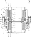
FIG. 1 is a sectional view of a fluid loading joint according to Embodiment 1 of the present invention. -
FIG. 2 is an enlarged view of a part ofFIG. 1 . -
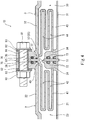
FIG. 3 is an enlarged sectional view of a part of a fluid loading joint according toEmbodiment 2 of the present invention. -
FIG. 4 shows a variation ofEmbodiment 2. -
FIG. 5 is a sectional view of a conventional fluid loading joint. -
FIG. 1 andFIG. 2 show afluid loading joint 1A according to Embodiment 1 of the present invention. The fluid loading joint 1A constitutes a part of fluid loading equipment (loading arm) 10 intended for liquefied hydrogen. The fluid loading equipment (loading arm) 10 is connected to, for example, a liquefied hydrogen carrier ship. - The fluid loading joint 1A connects a first vacuum
double pipe 11 and a second vacuumdouble pipe 14 to each other. In the present embodiment, the fluid loading joint 1A is a swivel joint. The fluid loading joint 1A includes afirst half 2 and asecond half 3. Thefirst half 2 is provided at an end of the first vacuumdouble pipe 11. Thesecond half 3 is provided at an end of the second vacuumdouble pipe 14. - The first vacuum
double pipe 11 includes afirst conduit pipe 12 and a firstaccommodating pipe 13. Liquefied hydrogen flows through the inside of thefirst conduit pipe 12. The firstaccommodating pipe 13 accommodates thefirst conduit pipe 12 therein. A vacuum is drawn on the space between thefirst conduit pipe 12 and the firstaccommodating pipe 13. Similarly, the second vacuumdouble pipe 14 includes asecond conduit pipe 15 and a secondaccommodating pipe 16. Liquefied hydrogen flows through the inside of thesecond conduit pipe 15. The secondaccommodating pipe 16 accommodates thesecond conduit pipe 15 therein. A vacuum is drawn on the space between thesecond conduit pipe 15 and the secondaccommodating pipe 16. - The
first half 2 includes a firstinner pipe 21 and a firstouter pipe 22. The firstouter pipe 22 accommodates the firstinner pipe 21 therein. Thefirst conduit pipe 12 is joined, for example by welding, to the proximal end of the first inner pipe 21 (i.e., the opposite end from the second half 3). The firstaccommodating pipe 13 is joined, for example by welding, to the proximal end of the firstouter pipe 22. Afirst vacuum space 23 is formed between the firstinner pipe 21 and the firstouter pipe 22. It should be noted that the position of the proximal end of the firstinner pipe 21 and the position of the proximal end of the firstouter pipe 22 may be shifted from each other in the axial direction. - Similarly, the
second half 3 includes a secondinner pipe 31 and a secondouter pipe 32. The secondouter pipe 32 accommodates the secondinner pipe 31 therein. Thesecond conduit pipe 15 is joined, for example by welding, to the proximal end of the second inner pipe 31 (i.e., the opposite end from the first half 2). The secondaccommodating pipe 16 is joined, for example by welding, to the proximal end of the secondouter pipe 32. Asecond vacuum space 33 is formed between the secondinner pipe 31 and the secondouter pipe 32. It should be noted that the position of the proximal end of the secondinner pipe 31 and the position of the proximal end of the secondouter pipe 32 may be shifted from each other in the axial direction. - The first
outer pipe 22 and the secondouter pipe 32 expand in diameter, except at their proximal end portions. In the present embodiment, as mentioned above, the fluid loading joint 1A is a swivel joint. Thefirst half 2 is the movable side, and thesecond half 3 is the fixed side. For this reason, the internal diameter of the distal end of the secondouter pipe 32 is greater than the internal diameter of the distal end of the firstouter pipe 22. - The
first half 2 further includes an annular first blockingmember 41, which blocks between the firstinner pipe 21 and the firstouter pipe 22. In the present embodiment, the first blockingmember 41 is located at a position deeper than the joint surface of the first half 2 (the joint surface is constituted by the distal end surface of a firstinner flange 24 and the distal end surface of aholder 25; the firstinner flange 24 and theholder 25 will be described below). Further, in the present embodiment, the inner end portion of the first blockingmember 41 is joined to the proximal end surface of the firstinner flange 24, which is provided at the distal end of the firstinner pipe 21. The outer end portion of the first blockingmember 41 is joined to the inner circumferential surface of the firstouter pipe 22 at a position that is slightly shifted from the distal end of the first outer pipe 22 (i.e., the end facing the second half 3) toward the proximal end of the firstouter pipe 22. - The
first blocking member 41 includes at least oneannular groove 42, which is recessed into thefirst vacuum space 23 along the firstinner pipe 21. It should be noted that, desirably, a plurality of concentricannular grooves 42 are provided such that the first blockingmember 41 is bellows-shaped when seen in a sectional view. In the present embodiment, the first blockingmember 41 includes two concentricannular grooves 42. Desirably, theannular grooves 42 are made sufficiently deep. For example, the depth of theannular grooves 42 may be greater than the distance from the firstinner pipe 21 to the firstouter pipe 22, the distance being measured at a position where the first blockingmember 41 is present. - The space between the first blocking
member 41 and the firstinner pipe 21, the space between the first blockingmember 41 and the firstouter pipe 22, and the space between theannular grooves 42 of the first blockingmember 41 are part of the aforementionedfirst vacuum space 23. On the other hand, as described below, the inside of theannular grooves 42 is filled with helium gas. In this manner, vacuum layers and helium gas layers are alternately formed by the first blockingmember 41 in the radial direction. - Similarly, the
second half 3 further includes an annular second blockingmember 43, which blocks between the secondinner pipe 31 and the secondouter pipe 32. In the present embodiment, the second blockingmember 43 is located at a position deeper than the joint surface of the second half 3 (the joint surface is constituted by the distal end surface of a secondinner flange 34 and the distal end surface of a secondouter flange 35; the secondinner flange 34 and the secondouter flange 35 will be described below). Further, in the present embodiment, the inner end portion of the second blockingmember 43 is joined to the proximal end surface of the secondinner flange 34, which is provided at the distal end of the secondinner pipe 31. The outer end portion of the second blockingmember 43 is joined to the inner circumferential surface of the secondouter pipe 32 at a position that is slightly shifted from the distal end of the second outer pipe 32 (i.e., the end facing the first half 2) toward the proximal end of the secondouter pipe 32. - The
second blocking member 43 includes at least oneannular groove 44, which is recessed into thesecond vacuum space 33 along the secondinner pipe 31. It should be noted that, desirably, a plurality of concentricannular grooves 44 are provided such that the second blockingmember 43 is bellows-shaped when seen in a sectional view. In the present embodiment, the second blockingmember 43 includes three concentricannular grooves 44. Desirably, theannular grooves 44 are made sufficiently deep. For example, the depth of theannular grooves 44 may be greater than the distance from the secondinner pipe 31 to the secondouter pipe 32, the distance being measured at a position where the second blockingmember 43 is present. - The space between the second blocking
member 43 and the secondinner pipe 31, the space between the second blockingmember 43 and the secondouter pipe 32, and the spaces between theannular grooves 44 of the second blockingmember 43 are part of the aforementionedsecond vacuum space 33. On the other hand, as described below, the inside of theannular grooves 44 is filled with helium gas. In this manner, vacuum layers and helium gas layers are alternately formed by the second blockingmember 43 in the radial direction. - An annular
inner spacer 61 and an annularinner insulator 51 are interposed between the firstinner flange 24 and the secondinner flange 34. Thecylindrical holder 25, an annularouter spacer 62, and an annularouter insulator 52 are interposed between the firstouter pipe 22 and the secondouter pipe 32. - The
holder 25 is a component of thefirst half 2, and holds the firstouter pipe 22 viabearings 26, such that the firstouter pipe 22 is rotatable. Meanwhile, the secondouter flange 35 is provided at the distal end of the secondouter pipe 32. Theouter spacer 62 and theouter insulator 52 are interposed between theholder 25 and the secondouter flange 35. To be more specific, theouter insulator 52 is sandwiched between theouter spacer 62 and the secondouter flange 35. - The second
outer flange 35 is fastened to theholder 25 bybolts 91. Each of theouter insulator 52 and theouter spacer 62 is provided with insertion holes for thebolts 91. In the present embodiment, theholder 25 is provided with screw holes in which thebolts 91 are screwed. Alternatively, instead of the screw holes, theholder 25 may be provided with insertion holes, and in this case, nuts may be used. - The
inner spacer 61 is disposed inside theouter spacer 62, and has the same thickness as that of theouter spacer 62. However, theinner spacer 61 and theouter spacer 62 may have different thicknesses from each other. Each of theinner spacer 61 and theouter spacer 62 is made of a metal. - The
inner insulator 51 is disposed inside theouter insulator 52, and has the same thickness as that of theouter insulator 52. However, theinner insulator 51 and theouter insulator 52 may have different thicknesses from each other. Each of theinner insulator 51 and theouter insulator 52 is made of an insulating material (e.g., a resin such as commodity plastic or engineering plastic). - The
inner spacer 61 is fastened to the secondinner flange 34 bybolts 92, and slides on the firstinner flange 24.Sealing members 71 for preventing the liquefied hydrogen from leaking through a gap between the firstinner flange 24 and theinner spacer 61 are disposed between the firstinner flange 24 and theinner spacer 61. It should be noted that a slight clearance is formed between the firstinner flange 24 and theinner spacer 61, and the sealingmembers 71 held by the firstinner flange 24 slide on theinner spacer 61. In the present embodiment, aring 46 is fitted to the distal end of the firstinner pipe 21, such that thering 46 obscures theinner sealing members 71 from the inside. - The
inner insulator 51 is sandwiched between theinner spacer 61 and the secondinner flange 34. Theinner insulator 51 is provided with insertion holes for thebolts 92.Sealing members 72 for preventing the liquefied hydrogen from leaking through a gap between theinner spacer 61 and theinner insulator 51 are disposed between theinner spacer 61 and theinner insulator 51, and sealingmembers 73 for preventing the liquefied hydrogen from leaking through a gap between theinner insulator 51 and the secondinner flange 34 are disposed between theinner insulator 51 and the secondinner flange 34. - A gap between the
inner spacer 61 and theouter spacer 62, and a gap between theinner insulator 51 and theouter insulator 52, communicate with a space between the distal end of the firstinner pipe 21 and the distal end of the firstouter pipe 22, the space having the first blockingmember 41 as its bottom, and a space between the distal end of the secondinner pipe 31 and the distal end of the secondouter pipe 32, the space having the second blockingmember 43 as its bottom. These gaps and spaces constitute agas space 45. In other words, thegas space 45 is formed between the first blockingmember 41 and the second blockingmember 43; theouter spacer 62 surrounds theinner spacer 61, with thegas space 45 positioned between theouter spacer 62 and theinner spacer 61; and theouter insulator 52 surrounds theinner insulator 51, with thegas space 45 positioned between theouter insulator 52 and theinner insulator 51. - The
gas space 45 is filled with helium gas.Port members 27 for supplying the helium gas to thegas space 45 through a gap between the firstouter pipe 22 and theholder 25 are mounted to theholder 25. - A sealing
member 74 for preventing the entry of outside water is disposed between the firstouter pipe 22 and theholder 25.Sealing members 75 to 77 for preventing hydrogen gas from leaking to the outside are disposed between theholder 25, theouter spacer 62, theouter insulator 52, and the secondouter flange 35 so that the hydrogen gas will be prevented from leaking to the outside even when the liquefied hydrogen has leaked into thegas space 45 beyond the sealingmembers members 74 to 77 also serve to prevent the helium gas from leaking to the outside. - The
aforementioned bolts 91, which fasten the secondouter flange 35 to theholder 25, are made of a metal. Accordingly,sleeves 81 made of an insulating material are inserted in the aforementioned insertion holes for thebolts 91, the insertion holes being provided in theouter insulator 52 and theouter spacer 62.Seats 82 made of an insulating material are disposed between the secondouter flange 35 andwashers 83, which contact the heads of therespective bolts 91. - On the other hand, the
aforementioned bolts 92, which fasten theinner spacer 61 to the secondinner flange 34, are made of an insulating material. Alternatively, thebolts 92 may be made of a metal, and the same insulation measures as those adopted for thebolts 91 may be adopted for thebolts 92. - As described above, in the fluid loading joint 1A of the present embodiment, the
inner insulator 51 is interposed between the firstinner pipe 21 and the secondinner pipe 31, and theouter insulator 52 is interposed between the firstouter pipe 22 and the secondouter pipe 32. This makes it possible to electrically insulate thefirst half 2 and thesecond half 3 from each other. In addition, theinner insulator 51 and theouter insulator 52 are spaced apart from each other, with thegas space 45 positioned therebetween. Therefore, the transfer of external heat from theouter insulator 52 to theinner insulator 51 is suppressed, which makes it possible to achieve high thermal insulation performance. - Further, in the present embodiment, since the
outer insulator 52 is interposed between theholder 25 and the secondouter flange 35, theouter insulator 52 can be fixed by utilizing the fastening structure (i.e., the bolts 91) for fastening the secondouter flange 35 to theholder 25. - Still further, in the present embodiment, since the
inner insulator 51 is sandwiched between theinner spacer 61 and the secondinner flange 34, theinner insulator 51 can be fixed with a simple structure while keeping the clearance of the sliding part small by theinner spacer 61. -
FIG. 3 shows a fluid loading joint 1B according toEmbodiment 2 of the present invention. It should be noted that, in the present embodiment, the same components as those described in Embodiment 1 are denoted by the same reference signs as those used in Embodiment 1, and repeating the same descriptions is avoided. - In the present embodiment, the fluid loading joint 1B is a fixed joint. Therefore, the
first half 2 and thesecond half 3 have symmetrical shapes with each other. - Specifically, a first
outer flange 28 is provided at the distal end of the firstouter pipe 22 of thefirst half 2. The secondouter flange 35, which is provided at the distal end of the secondouter pipe 32, is fastened to the firstouter flange 28 by thebolts 91 and nuts 93. In the present embodiment, thewashers 83, and theseats 82 made of an insulating material, are disposed also between the nuts 93 and the firstouter flange 28. - In the present embodiment, the
inner insulator 51 is sandwiched between the firstinner flange 24 and the secondinner flange 34, and theouter insulator 52 is sandwiched between the firstouter flange 28 and the secondouter flange 35. The sealingmembers 72 for preventing the liquefied hydrogen from leaking through a gap between the firstinner flange 24 and theinner insulator 51 are disposed between the firstinner flange 24 and theinner insulator 51, and the sealingmembers 73 for preventing the liquefied hydrogen from leaking through a gap between theinner insulator 51 and the secondinner flange 34 are disposed between theinner insulator 51 and the secondinner flange 34. - In the present embodiment, the
gas space 45 formed between the first blockingmember 41 and the second blockingmember 43 is filled with hydrogen gas. The hydrogen gas is a result of evaporation of the liquefied hydrogen that has leaked through the gap between the firstinner flange 24 and theinner insulator 51 and the gap between theinner insulator 51 and the secondinner flange 34. Between the firstouter flange 28 and theouter insulator 52, and between theouter insulator 52 and the secondouter flange 35, the sealingmembers 75 to 77 for preventing the hydrogen gas from leaking through a gap between the firstouter flange 28 and theouter insulator 52 and a gap between theouter insulator 52 and the secondouter flange 35 are disposed. - The present embodiment further adopts a
positioning mechanism 55, which restricts the movement of theinner insulator 51 in the radial direction. Thepositioning mechanism 55 of the present embodiment is aprotrusion 56, which is provided on the outer circumferential edge portion of theinner insulator 51 and protrudes along the outer circumferential surface of the secondinner flange 34. - Also in the present embodiment, similar to Embodiment 1, the
first half 2 and thesecond half 3 can be electrically insulated from each other, and high thermal insulation performance can be achieved. In addition, since the present embodiment adopts thepositioning mechanism 55, theinner insulator 51 can be kept at a normal position. - It should be noted that the
positioning mechanism 55 need not be theprotrusion 56 provided on the outer circumferential edge portion of theinner insulator 51. For example, as shown inFIG. 4 , thepositioning mechanism 55 may be aprotrusion 57, which is provided on the firstinner flange 24 and engaged with the outer circumferential surface of theinner insulator 51. - The present invention is not limited to the above-described embodiments. Various modifications can be made without departing from the scope of the present invention.
- For example, in Embodiment 1, the
outer spacer 62 may be eliminated, and either one of the firstouter pipe 22 or the secondouter pipe 32 may be made longer by a length corresponding to the thickness of theouter spacer 62. -
- 1A, 1B
- fluid loading joint
- 10
- fluid loading equipment
- 2
- first half
- 21
- first inner pipe
- 22
- first outer pipe
- 23
- first vacuum space
- 24
- first inner flange
- 25
- holder
- 28
- first outer flange
- 3
- second half
- 31
- second inner pipe
- 32
- second outer pipe
- 33
- second vacuum space
- 34
- second inner flange
- 35
- second outer flange
- 41
- first blocking member
- 43
- second blocking member
- 45
- gas space
- 51
- inner insulator
- 52
- outer insulator
- 55
- positioning mechanism
- 61, 62
- spacer
Claims (7)
- A fluid loading joint comprising:a first half provided at an end of a first vacuum double pipe, the first half including a first inner pipe, a first outer pipe, and a first blocking member, the first outer pipe forming a vacuum space between the first inner pipe and the first outer pipe, the first blocking member blocking between the first inner pipe and the first outer pipe;a second half provided at an end of a second vacuum double pipe, the second half including a second inner pipe, a second outer pipe, and a second blocking member, the second outer pipe forming a vacuum space between the second inner pipe and the second outer pipe, the second blocking member blocking between the second inner pipe and the second outer pipe and forming a gas space between the first blocking member and the second blocking member, the gas space being filled with gas;an annular inner insulator interposed between the first inner pipe and the second inner pipe; andan annular outer insulator interposed between the first outer pipe and the second outer pipe, the outer insulator surrounding the inner insulator, with the gas space positioned between the outer insulator and the inner insulator.
- The fluid loading joint according to claim 1, wherein
a first inner flange is provided at a distal end of the first inner pipe,
a second inner flange is provided at a distal end of the second inner pipe, and
the inner insulator is interposed between the first inner flange and the second inner flange. - The fluid loading joint according to claim 2, wherein
the fluid loading joint is a swivel joint,
the first half includes a cylindrical holder that holds the first outer pipe such that the first outer pipe is rotatable,
an outer flange that is fastened to the holder is provided at a distal end of the second outer pipe, and
the outer insulator is interposed between the holder and the outer flange. - The fluid loading joint according claim 3, further comprising a spacer interposed between the first inner flange and the second inner flange, the spacer being fastened to the second inner flange and slidable on the first inner flange, wherein
the inner insulator is sandwiched between the spacer and the second inner flange. - The fluid loading joint according to claim 2, wherein
the fluid loading joint is a fixed joint,
a first outer flange is provided at a distal end of the first outer pipe,
a second outer flange that is fastened to the first outer flange is provided at a distal end of the second outer pipe,
the inner insulator is sandwiched between the first inner flange and the second inner flange, and
the outer insulator is sandwiched between the first outer flange and the second outer flange. - The fluid loading joint according to claim 5, further comprising a positioning mechanism that restricts movement of the inner insulator in a radial direction.
- Fluid loading equipment comprising the fluid loading joint according to any one of claims 1 to 6.
Applications Claiming Priority (2)
| Application Number | Priority Date | Filing Date | Title |
|---|---|---|---|
| JP2017254139A JP7152857B2 (en) | 2017-12-28 | 2017-12-28 | Fluid handling fittings and fluid handling equipment |
| PCT/JP2018/047905 WO2019131783A1 (en) | 2017-12-28 | 2018-12-26 | Loading arm connector and loading arm |
Publications (3)
| Publication Number | Publication Date |
|---|---|
| EP3734131A1 true EP3734131A1 (en) | 2020-11-04 |
| EP3734131A4 EP3734131A4 (en) | 2021-08-25 |
| EP3734131B1 EP3734131B1 (en) | 2023-08-02 |
Family
ID=67066444
Family Applications (1)
| Application Number | Title | Priority Date | Filing Date |
|---|---|---|---|
| EP18896842.4A Active EP3734131B1 (en) | 2017-12-28 | 2018-12-26 | Fluid loading joint and fluid loading equipment |
Country Status (6)
| Country | Link |
|---|---|
| US (1) | US11608263B2 (en) |
| EP (1) | EP3734131B1 (en) |
| JP (1) | JP7152857B2 (en) |
| CN (1) | CN111512081B (en) |
| DK (1) | DK3734131T3 (en) |
| WO (1) | WO2019131783A1 (en) |
Families Citing this family (18)
| Publication number | Priority date | Publication date | Assignee | Title |
|---|---|---|---|---|
| FR3119007B1 (en) * | 2021-01-19 | 2023-02-24 | Air Liquide | Emergency coupling and detachment device |
| FR3119005B1 (en) * | 2021-01-19 | 2023-10-06 | Air Liquide | Emergency coupling and detachment device |
| WO2022251878A1 (en) * | 2021-05-28 | 2022-12-01 | Engineered Controls International, Llc | Low-emission nozzle and receptacle coupling for cryogenic fluid |
| FR3127543A1 (en) * | 2021-09-28 | 2023-03-31 | Airbus Operations (S.A.S.) | Double skin hydrogen pipe comprising at least one leak detection system at the level of at least one connection system, aircraft comprising at least one such pipe |
| FR3127541A1 (en) * | 2021-09-30 | 2023-03-31 | Thomas Issler | Two-phase connector |
| KR102431373B1 (en) * | 2021-12-20 | 2022-08-10 | 반태행 | Swivel joint with insulation and vacuum for cryogenic environment of lng bunkering |
| KR102420434B1 (en) * | 2021-12-20 | 2022-07-14 | 반태행 | Swivel joint with insulation for cryogenic environment of lng bunkering |
| FR3131949B1 (en) * | 2022-01-17 | 2023-12-08 | Air Liquide | Coupling device and its purging process |
| EP4239239B1 (en) | 2022-01-19 | 2026-04-08 | Airbus Operations Limited | Coupling for insulated piping |
| CN114593289A (en) * | 2022-03-31 | 2022-06-07 | 中海石油气电集团有限责任公司 | A rotary joint device for LNG cryogenic unloading system |
| NL2031473B1 (en) | 2022-04-01 | 2023-10-24 | Kanon Loading Equipment B V | Fluid loading coupling for rotatable coupling of fluid conduits for cryogenic fluids |
| DE102022110880A1 (en) * | 2022-05-03 | 2023-11-09 | Witzenmann Gmbh | Connection arrangement for a cryogenic line and cryogenic line |
| EP4299960B1 (en) | 2022-07-01 | 2025-04-16 | Airbus Operations GmbH | Hydrogen pipe coupling arrangement with enhanced inner sealing |
| US12590666B2 (en) | 2022-09-28 | 2026-03-31 | Airbus Operations Limited | Coupling for insulated piping |
| US12098794B2 (en) * | 2023-02-24 | 2024-09-24 | VJ Systems, LLC | Cryogenic rotating seal |
| DE102023118143A1 (en) * | 2023-07-10 | 2025-01-16 | PFW Aerospace GmbH | pipe connection for cryogenic media |
| JP2026066578A (en) * | 2024-10-07 | 2026-04-17 | 川崎重工業株式会社 | Swivel joints and joint systems |
| JP2026122057A (en) * | 2025-01-15 | 2026-07-28 | 川崎重工業株式会社 | Cargo handling system |
Family Cites Families (26)
| Publication number | Priority date | Publication date | Assignee | Title |
|---|---|---|---|---|
| US236519A (en) * | 1881-01-11 | Hamilton Mark K | Receptable | |
| US2957709A (en) * | 1946-03-01 | 1960-10-25 | Charles W Skarstrom | Sealing means for relatively rotatable members |
| US2877026A (en) * | 1954-02-09 | 1959-03-10 | Crane Packing Co | Sealing device for a swivel joint having plural fluid passages |
| FR1230498A (en) * | 1959-02-12 | 1960-09-16 | Prec Ind | Machine tool spindle with incorporated hydraulic motor |
| US3180661A (en) * | 1962-12-06 | 1965-04-27 | Gordon H Porath | Rotary hydraulic fitting |
| FR1399258A (en) * | 1964-06-19 | 1965-05-14 | Worthington Corp | Fluid transport pipe fitting |
| US3371946A (en) | 1965-10-02 | 1968-03-05 | Gustave A. Bleyle Jr. | Cryogenic coupling |
| US3775989A (en) * | 1971-03-31 | 1973-12-04 | Amtek Inc | Rotary cryogenic couplings |
| SU583778A3 (en) * | 1973-06-16 | 1977-12-05 | Ili Khivari | Controllable clutch |
| US4040338A (en) * | 1976-06-14 | 1977-08-09 | Logansport Machine Co., Inc. | Fluid supply distributor |
| JPS5669318A (en) * | 1979-11-10 | 1981-06-10 | Nippon Steel Corp | Rotating joint for converter |
| JPS594888U (en) * | 1982-06-30 | 1984-01-12 | 大阪瓦斯株式会社 | Insulating gasket |
| JPS6091889U (en) * | 1983-11-30 | 1985-06-22 | 三菱重工業株式会社 | Cryogenic fluid double piping fitting |
| DE3819390C2 (en) * | 1988-06-07 | 1994-05-26 | Glyco Antriebstechnik Gmbh | Hydrostatic rotary union |
| DE4103376C1 (en) * | 1991-02-05 | 1992-08-06 | Ott Maschinentechnik Gmbh, 8960 Kempten, De | |
| DE4107652A1 (en) * | 1991-03-09 | 1992-09-10 | Bayerische Motoren Werke Ag | Double-walled pipe coupling - has one pipe expanded to enclose other, and has elastic seals sealing ring chamber between two pipes |
| FR2746891B1 (en) * | 1996-03-29 | 1998-06-05 | Itp | PIPE FOR DUAL THERMAL INSULATING PIPE TYPE PIPES |
| JP2975923B1 (en) * | 1998-05-22 | 1999-11-10 | 日本ピラー工業株式会社 | Rotary joint device |
| JP4189181B2 (en) * | 2002-08-22 | 2008-12-03 | イーグル工業株式会社 | Rotary joint |
| US8113545B2 (en) * | 2005-12-28 | 2012-02-14 | Eagle Industry Co., Ltd. | Rotary joint |
| CN201141489Y (en) * | 2007-12-07 | 2008-10-29 | 张家港市华瑞科技有限公司 | Butt joint structure of vacuum tube |
| US8205643B2 (en) * | 2008-10-16 | 2012-06-26 | Woodward, Inc. | Multi-tubular fluid transfer conduit |
| JP2014043261A (en) | 2012-08-27 | 2014-03-13 | Niigata Loading Systems Ltd | Fluid cargo handling device |
| CN103322357B (en) * | 2013-05-15 | 2015-01-07 | 中国科学院等离子体物理研究所 | Compound liquid nitrogen liquid helium delivery pipe joint with potential isolating function |
| JP6396264B2 (en) * | 2015-07-10 | 2018-09-26 | 東京貿易エンジニアリング株式会社 | Fluid handling equipment for liquid hydrogen |
| EP4299964B1 (en) * | 2017-10-09 | 2025-12-10 | Deublin Company, LLC | Multiple passage rotary union |
-
2017
- 2017-12-28 JP JP2017254139A patent/JP7152857B2/en active Active
-
2018
- 2018-12-26 CN CN201880083811.9A patent/CN111512081B/en active Active
- 2018-12-26 DK DK18896842.4T patent/DK3734131T3/en active
- 2018-12-26 WO PCT/JP2018/047905 patent/WO2019131783A1/en not_active Ceased
- 2018-12-26 EP EP18896842.4A patent/EP3734131B1/en active Active
- 2018-12-26 US US16/958,806 patent/US11608263B2/en active Active
Also Published As
| Publication number | Publication date |
|---|---|
| WO2019131783A1 (en) | 2019-07-04 |
| US11608263B2 (en) | 2023-03-21 |
| CN111512081B (en) | 2022-11-04 |
| DK3734131T3 (en) | 2023-10-16 |
| JP7152857B2 (en) | 2022-10-13 |
| US20210061640A1 (en) | 2021-03-04 |
| EP3734131A4 (en) | 2021-08-25 |
| CN111512081A (en) | 2020-08-07 |
| JP2019120286A (en) | 2019-07-22 |
| EP3734131B1 (en) | 2023-08-02 |
Similar Documents
| Publication | Publication Date | Title |
|---|---|---|
| US11608263B2 (en) | Fluid loading joint and fluid loading equipment | |
| US11608923B2 (en) | Fluid loading joint | |
| JP2021113614A (en) | Johnston coupling with additional vacuum enclosure | |
| EP2756567B1 (en) | High temperature, high pressure subsea electrical connector system | |
| US9899816B2 (en) | Pressure compensator and electrical connection device | |
| JP6480693B2 (en) | Joint structure of vacuum insulated double pipe for cryogenic fluid | |
| ITCO20090061A1 (en) | HEATING CONTAINER FOR COMPRESSOR HEAD | |
| CN105186439B (en) | Cable joint seal structure of high-temperature electric submersible pump | |
| JP5927072B2 (en) | mechanical seal | |
| US10823291B2 (en) | Mechanical seal | |
| US10113683B2 (en) | Transfer line for cryogenic liquid | |
| JP2021113615A (en) | Johnston coupling with galvanic insulation | |
| CN210601025U (en) | Cryogenic storage tank | |
| JP5801008B1 (en) | Double sealed terminal header | |
| CN112460471B (en) | Cryogenic storage tank | |
| US4188038A (en) | Seal arrangement for intersecting conduits | |
| JP6555819B2 (en) | Temperature measuring device | |
| WO2015125959A1 (en) | Seal mechanism | |
| US8794007B2 (en) | Rocket propulsion device and method for assembling rocket propulsion device | |
| JP6133641B2 (en) | Insulation universal joint | |
| CN206754367U (en) | A kind of bellows protective case | |
| CN106931163A (en) | A kind of bellows protective case | |
| CN113669451A (en) | A kind of sealing structure and its application in high temperature and high pressure system | |
| WO2025143106A1 (en) | Connection member and cooling device | |
| JP2019002532A (en) | Heat insulation equipment |
Legal Events
| Date | Code | Title | Description |
|---|---|---|---|
| STAA | Information on the status of an ep patent application or granted ep patent |
Free format text: STATUS: THE INTERNATIONAL PUBLICATION HAS BEEN MADE |
|
| PUAI | Public reference made under article 153(3) epc to a published international application that has entered the european phase |
Free format text: ORIGINAL CODE: 0009012 |
|
| STAA | Information on the status of an ep patent application or granted ep patent |
Free format text: STATUS: REQUEST FOR EXAMINATION WAS MADE |
|
| 17P | Request for examination filed |
Effective date: 20200715 |
|
| AK | Designated contracting states |
Kind code of ref document: A1 Designated state(s): AL AT BE BG CH CY CZ DE DK EE ES FI FR GB GR HR HU IE IS IT LI LT LU LV MC MK MT NL NO PL PT RO RS SE SI SK SM TR |
|
| AX | Request for extension of the european patent |
Extension state: BA ME |
|
| DAV | Request for validation of the european patent (deleted) | ||
| DAX | Request for extension of the european patent (deleted) | ||
| A4 | Supplementary search report drawn up and despatched |
Effective date: 20210722 |
|
| RIC1 | Information provided on ipc code assigned before grant |
Ipc: F16L 25/02 20060101AFI20210716BHEP Ipc: B67D 9/02 20100101ALI20210716BHEP Ipc: F16L 59/075 20060101ALI20210716BHEP Ipc: F16L 59/18 20060101ALI20210716BHEP Ipc: F16L 39/00 20060101ALI20210716BHEP Ipc: F16L 39/04 20060101ALI20210716BHEP |
|
| RAP1 | Party data changed (applicant data changed or rights of an application transferred) |
Owner name: KAWASAKI JUKOGYO KABUSHIKI KAISHA Owner name: TB GLOBAL TECHNOLOGIES LTD. |
|
| RAP1 | Party data changed (applicant data changed or rights of an application transferred) |
Owner name: T.EN LOADING SYSTEMS S.A.S. Owner name: TB GLOBAL TECHNOLOGIES LTD. Owner name: KAWASAKI JUKOGYO KABUSHIKI KAISHA |
|
| GRAP | Despatch of communication of intention to grant a patent |
Free format text: ORIGINAL CODE: EPIDOSNIGR1 |
|
| STAA | Information on the status of an ep patent application or granted ep patent |
Free format text: STATUS: GRANT OF PATENT IS INTENDED |
|
| GRAJ | Information related to disapproval of communication of intention to grant by the applicant or resumption of examination proceedings by the epo deleted |
Free format text: ORIGINAL CODE: EPIDOSDIGR1 |
|
| INTG | Intention to grant announced |
Effective date: 20230323 |
|
| INTG | Intention to grant announced |
Effective date: 20230323 |
|
| GRAS | Grant fee paid |
Free format text: ORIGINAL CODE: EPIDOSNIGR3 |
|
| GRAA | (expected) grant |
Free format text: ORIGINAL CODE: 0009210 |
|
| STAA | Information on the status of an ep patent application or granted ep patent |
Free format text: STATUS: THE PATENT HAS BEEN GRANTED |
|
| AK | Designated contracting states |
Kind code of ref document: B1 Designated state(s): AL AT BE BG CH CY CZ DE DK EE ES FI FR GB GR HR HU IE IS IT LI LT LU LV MC MK MT NL NO PL PT RO RS SE SI SK SM TR |
|
| REG | Reference to a national code |
Ref country code: GB Ref legal event code: FG4D |
|
| REG | Reference to a national code |
Ref country code: CH Ref legal event code: EP |
|
| REG | Reference to a national code |
Ref country code: DE Ref legal event code: R096 Ref document number: 602018054796 Country of ref document: DE |
|
| REG | Reference to a national code |
Ref country code: NL Ref legal event code: FP Ref country code: IE Ref legal event code: FG4D |
|
| REG | Reference to a national code |
Ref country code: SE Ref legal event code: TRGR |
|
| REG | Reference to a national code |
Ref country code: DK Ref legal event code: T3 Effective date: 20231012 Ref country code: NO Ref legal event code: T2 Effective date: 20230802 |
|
| REG | Reference to a national code |
Ref country code: LT Ref legal event code: MG9D |
|
| REG | Reference to a national code |
Ref country code: AT Ref legal event code: MK05 Ref document number: 1595124 Country of ref document: AT Kind code of ref document: T Effective date: 20230802 |
|
| PG25 | Lapsed in a contracting state [announced via postgrant information from national office to epo] |
Ref country code: GR Free format text: LAPSE BECAUSE OF FAILURE TO SUBMIT A TRANSLATION OF THE DESCRIPTION OR TO PAY THE FEE WITHIN THE PRESCRIBED TIME-LIMIT Effective date: 20231103 |
|
| PG25 | Lapsed in a contracting state [announced via postgrant information from national office to epo] |
Ref country code: IS Free format text: LAPSE BECAUSE OF FAILURE TO SUBMIT A TRANSLATION OF THE DESCRIPTION OR TO PAY THE FEE WITHIN THE PRESCRIBED TIME-LIMIT Effective date: 20231202 |
|
| PG25 | Lapsed in a contracting state [announced via postgrant information from national office to epo] |
Ref country code: RS Free format text: LAPSE BECAUSE OF FAILURE TO SUBMIT A TRANSLATION OF THE DESCRIPTION OR TO PAY THE FEE WITHIN THE PRESCRIBED TIME-LIMIT Effective date: 20230802 Ref country code: PT Free format text: LAPSE BECAUSE OF FAILURE TO SUBMIT A TRANSLATION OF THE DESCRIPTION OR TO PAY THE FEE WITHIN THE PRESCRIBED TIME-LIMIT Effective date: 20231204 Ref country code: LV Free format text: LAPSE BECAUSE OF FAILURE TO SUBMIT A TRANSLATION OF THE DESCRIPTION OR TO PAY THE FEE WITHIN THE PRESCRIBED TIME-LIMIT Effective date: 20230802 Ref country code: LT Free format text: LAPSE BECAUSE OF FAILURE TO SUBMIT A TRANSLATION OF THE DESCRIPTION OR TO PAY THE FEE WITHIN THE PRESCRIBED TIME-LIMIT Effective date: 20230802 Ref country code: IS Free format text: LAPSE BECAUSE OF FAILURE TO SUBMIT A TRANSLATION OF THE DESCRIPTION OR TO PAY THE FEE WITHIN THE PRESCRIBED TIME-LIMIT Effective date: 20231202 Ref country code: HR Free format text: LAPSE BECAUSE OF FAILURE TO SUBMIT A TRANSLATION OF THE DESCRIPTION OR TO PAY THE FEE WITHIN THE PRESCRIBED TIME-LIMIT Effective date: 20230802 Ref country code: GR Free format text: LAPSE BECAUSE OF FAILURE TO SUBMIT A TRANSLATION OF THE DESCRIPTION OR TO PAY THE FEE WITHIN THE PRESCRIBED TIME-LIMIT Effective date: 20231103 Ref country code: FI Free format text: LAPSE BECAUSE OF FAILURE TO SUBMIT A TRANSLATION OF THE DESCRIPTION OR TO PAY THE FEE WITHIN THE PRESCRIBED TIME-LIMIT Effective date: 20230802 Ref country code: AT Free format text: LAPSE BECAUSE OF FAILURE TO SUBMIT A TRANSLATION OF THE DESCRIPTION OR TO PAY THE FEE WITHIN THE PRESCRIBED TIME-LIMIT Effective date: 20230802 |
|
| PG25 | Lapsed in a contracting state [announced via postgrant information from national office to epo] |
Ref country code: PL Free format text: LAPSE BECAUSE OF FAILURE TO SUBMIT A TRANSLATION OF THE DESCRIPTION OR TO PAY THE FEE WITHIN THE PRESCRIBED TIME-LIMIT Effective date: 20230802 |
|
| PG25 | Lapsed in a contracting state [announced via postgrant information from national office to epo] |
Ref country code: ES Free format text: LAPSE BECAUSE OF FAILURE TO SUBMIT A TRANSLATION OF THE DESCRIPTION OR TO PAY THE FEE WITHIN THE PRESCRIBED TIME-LIMIT Effective date: 20230802 |
|
| PG25 | Lapsed in a contracting state [announced via postgrant information from national office to epo] |
Ref country code: SM Free format text: LAPSE BECAUSE OF FAILURE TO SUBMIT A TRANSLATION OF THE DESCRIPTION OR TO PAY THE FEE WITHIN THE PRESCRIBED TIME-LIMIT Effective date: 20230802 Ref country code: RO Free format text: LAPSE BECAUSE OF FAILURE TO SUBMIT A TRANSLATION OF THE DESCRIPTION OR TO PAY THE FEE WITHIN THE PRESCRIBED TIME-LIMIT Effective date: 20230802 Ref country code: ES Free format text: LAPSE BECAUSE OF FAILURE TO SUBMIT A TRANSLATION OF THE DESCRIPTION OR TO PAY THE FEE WITHIN THE PRESCRIBED TIME-LIMIT Effective date: 20230802 Ref country code: EE Free format text: LAPSE BECAUSE OF FAILURE TO SUBMIT A TRANSLATION OF THE DESCRIPTION OR TO PAY THE FEE WITHIN THE PRESCRIBED TIME-LIMIT Effective date: 20230802 Ref country code: CZ Free format text: LAPSE BECAUSE OF FAILURE TO SUBMIT A TRANSLATION OF THE DESCRIPTION OR TO PAY THE FEE WITHIN THE PRESCRIBED TIME-LIMIT Effective date: 20230802 Ref country code: SK Free format text: LAPSE BECAUSE OF FAILURE TO SUBMIT A TRANSLATION OF THE DESCRIPTION OR TO PAY THE FEE WITHIN THE PRESCRIBED TIME-LIMIT Effective date: 20230802 |
|
| REG | Reference to a national code |
Ref country code: DE Ref legal event code: R097 Ref document number: 602018054796 Country of ref document: DE |
|
| PLBE | No opposition filed within time limit |
Free format text: ORIGINAL CODE: 0009261 |
|
| STAA | Information on the status of an ep patent application or granted ep patent |
Free format text: STATUS: NO OPPOSITION FILED WITHIN TIME LIMIT |
|
| 26N | No opposition filed |
Effective date: 20240503 |
|
| PG25 | Lapsed in a contracting state [announced via postgrant information from national office to epo] |
Ref country code: SI Free format text: LAPSE BECAUSE OF FAILURE TO SUBMIT A TRANSLATION OF THE DESCRIPTION OR TO PAY THE FEE WITHIN THE PRESCRIBED TIME-LIMIT Effective date: 20230802 |
|
| REG | Reference to a national code |
Ref country code: CH Ref legal event code: PL |
|
| PG25 | Lapsed in a contracting state [announced via postgrant information from national office to epo] |
Ref country code: LU Free format text: LAPSE BECAUSE OF NON-PAYMENT OF DUE FEES Effective date: 20231226 |
|
| PG25 | Lapsed in a contracting state [announced via postgrant information from national office to epo] |
Ref country code: MC Free format text: LAPSE BECAUSE OF FAILURE TO SUBMIT A TRANSLATION OF THE DESCRIPTION OR TO PAY THE FEE WITHIN THE PRESCRIBED TIME-LIMIT Effective date: 20230802 |
|
| PG25 | Lapsed in a contracting state [announced via postgrant information from national office to epo] |
Ref country code: MC Free format text: LAPSE BECAUSE OF FAILURE TO SUBMIT A TRANSLATION OF THE DESCRIPTION OR TO PAY THE FEE WITHIN THE PRESCRIBED TIME-LIMIT Effective date: 20230802 Ref country code: LU Free format text: LAPSE BECAUSE OF NON-PAYMENT OF DUE FEES Effective date: 20231226 |
|
| REG | Reference to a national code |
Ref country code: IE Ref legal event code: MM4A |
|
| PG25 | Lapsed in a contracting state [announced via postgrant information from national office to epo] |
Ref country code: IE Free format text: LAPSE BECAUSE OF NON-PAYMENT OF DUE FEES Effective date: 20231226 |
|
| PG25 | Lapsed in a contracting state [announced via postgrant information from national office to epo] |
Ref country code: CH Free format text: LAPSE BECAUSE OF NON-PAYMENT OF DUE FEES Effective date: 20231231 |
|
| PG25 | Lapsed in a contracting state [announced via postgrant information from national office to epo] |
Ref country code: IE Free format text: LAPSE BECAUSE OF NON-PAYMENT OF DUE FEES Effective date: 20231226 Ref country code: CH Free format text: LAPSE BECAUSE OF NON-PAYMENT OF DUE FEES Effective date: 20231231 |
|
| PG25 | Lapsed in a contracting state [announced via postgrant information from national office to epo] |
Ref country code: BG Free format text: LAPSE BECAUSE OF FAILURE TO SUBMIT A TRANSLATION OF THE DESCRIPTION OR TO PAY THE FEE WITHIN THE PRESCRIBED TIME-LIMIT Effective date: 20230802 |
|
| PG25 | Lapsed in a contracting state [announced via postgrant information from national office to epo] |
Ref country code: BG Free format text: LAPSE BECAUSE OF FAILURE TO SUBMIT A TRANSLATION OF THE DESCRIPTION OR TO PAY THE FEE WITHIN THE PRESCRIBED TIME-LIMIT Effective date: 20230802 |
|
| PG25 | Lapsed in a contracting state [announced via postgrant information from national office to epo] |
Ref country code: CY Free format text: LAPSE BECAUSE OF FAILURE TO SUBMIT A TRANSLATION OF THE DESCRIPTION OR TO PAY THE FEE WITHIN THE PRESCRIBED TIME-LIMIT; INVALID AB INITIO Effective date: 20181226 |
|
| PG25 | Lapsed in a contracting state [announced via postgrant information from national office to epo] |
Ref country code: HU Free format text: LAPSE BECAUSE OF FAILURE TO SUBMIT A TRANSLATION OF THE DESCRIPTION OR TO PAY THE FEE WITHIN THE PRESCRIBED TIME-LIMIT; INVALID AB INITIO Effective date: 20181226 |
|
| PG25 | Lapsed in a contracting state [announced via postgrant information from national office to epo] |
Ref country code: TR Free format text: LAPSE BECAUSE OF FAILURE TO SUBMIT A TRANSLATION OF THE DESCRIPTION OR TO PAY THE FEE WITHIN THE PRESCRIBED TIME-LIMIT Effective date: 20230802 |
|
| PGFP | Annual fee paid to national office [announced via postgrant information from national office to epo] |
Ref country code: NL Payment date: 20251112 Year of fee payment: 8 |
|
| PGFP | Annual fee paid to national office [announced via postgrant information from national office to epo] |
Ref country code: DE Payment date: 20251028 Year of fee payment: 8 |
|
| PGFP | Annual fee paid to national office [announced via postgrant information from national office to epo] |
Ref country code: GB Payment date: 20251114 Year of fee payment: 8 |
|
| PGFP | Annual fee paid to national office [announced via postgrant information from national office to epo] |
Ref country code: NO Payment date: 20251210 Year of fee payment: 8 |
|
| PGFP | Annual fee paid to national office [announced via postgrant information from national office to epo] |
Ref country code: IT Payment date: 20251121 Year of fee payment: 8 Ref country code: DK Payment date: 20251212 Year of fee payment: 8 |
|
| PGFP | Annual fee paid to national office [announced via postgrant information from national office to epo] |
Ref country code: FR Payment date: 20251110 Year of fee payment: 8 |
|
| PGFP | Annual fee paid to national office [announced via postgrant information from national office to epo] |
Ref country code: BE Payment date: 20251117 Year of fee payment: 8 |
|
| PGFP | Annual fee paid to national office [announced via postgrant information from national office to epo] |
Ref country code: SE Payment date: 20251112 Year of fee payment: 8 |