WO2015125959A1 - Seal mechanism - Google Patents
Seal mechanism Download PDFInfo
- Publication number
- WO2015125959A1 WO2015125959A1 PCT/JP2015/055049 JP2015055049W WO2015125959A1 WO 2015125959 A1 WO2015125959 A1 WO 2015125959A1 JP 2015055049 W JP2015055049 W JP 2015055049W WO 2015125959 A1 WO2015125959 A1 WO 2015125959A1
- Authority
- WO
- WIPO (PCT)
- Prior art keywords
- shaft
- seal lip
- stopper
- seal
- axis
- Prior art date
Links
Images


Classifications
-
- F—MECHANICAL ENGINEERING; LIGHTING; HEATING; WEAPONS; BLASTING
- F16—ENGINEERING ELEMENTS AND UNITS; GENERAL MEASURES FOR PRODUCING AND MAINTAINING EFFECTIVE FUNCTIONING OF MACHINES OR INSTALLATIONS; THERMAL INSULATION IN GENERAL
- F16J—PISTONS; CYLINDERS; SEALINGS
- F16J15/00—Sealings
- F16J15/16—Sealings between relatively-moving surfaces
- F16J15/32—Sealings between relatively-moving surfaces with elastic sealings, e.g. O-rings
- F16J15/3204—Sealings between relatively-moving surfaces with elastic sealings, e.g. O-rings with at least one lip
-
- F—MECHANICAL ENGINEERING; LIGHTING; HEATING; WEAPONS; BLASTING
- F16—ENGINEERING ELEMENTS AND UNITS; GENERAL MEASURES FOR PRODUCING AND MAINTAINING EFFECTIVE FUNCTIONING OF MACHINES OR INSTALLATIONS; THERMAL INSULATION IN GENERAL
- F16J—PISTONS; CYLINDERS; SEALINGS
- F16J15/00—Sealings
- F16J15/16—Sealings between relatively-moving surfaces
- F16J15/164—Sealings between relatively-moving surfaces the sealing action depending on movements; pressure difference, temperature or presence of leaking fluid
-
- F—MECHANICAL ENGINEERING; LIGHTING; HEATING; WEAPONS; BLASTING
- F16—ENGINEERING ELEMENTS AND UNITS; GENERAL MEASURES FOR PRODUCING AND MAINTAINING EFFECTIVE FUNCTIONING OF MACHINES OR INSTALLATIONS; THERMAL INSULATION IN GENERAL
- F16J—PISTONS; CYLINDERS; SEALINGS
- F16J15/00—Sealings
- F16J15/16—Sealings between relatively-moving surfaces
- F16J15/32—Sealings between relatively-moving surfaces with elastic sealings, e.g. O-rings
- F16J15/3204—Sealings between relatively-moving surfaces with elastic sealings, e.g. O-rings with at least one lip
- F16J15/322—Sealings between relatively-moving surfaces with elastic sealings, e.g. O-rings with at least one lip supported in a direction perpendicular to the surfaces
-
- F—MECHANICAL ENGINEERING; LIGHTING; HEATING; WEAPONS; BLASTING
- F16—ENGINEERING ELEMENTS AND UNITS; GENERAL MEASURES FOR PRODUCING AND MAINTAINING EFFECTIVE FUNCTIONING OF MACHINES OR INSTALLATIONS; THERMAL INSULATION IN GENERAL
- F16J—PISTONS; CYLINDERS; SEALINGS
- F16J15/00—Sealings
- F16J15/16—Sealings between relatively-moving surfaces
- F16J15/32—Sealings between relatively-moving surfaces with elastic sealings, e.g. O-rings
- F16J15/3204—Sealings between relatively-moving surfaces with elastic sealings, e.g. O-rings with at least one lip
- F16J15/3228—Sealings between relatively-moving surfaces with elastic sealings, e.g. O-rings with at least one lip formed by deforming a flat ring
Definitions
- the present invention relates to a sealing mechanism.
- This application claims priority based on Japanese Patent Application No. 2014-31553 for which it applied to Japan on February 21, 2014, and uses the content here.
- turbo pumps for rocket engines are extremely low temperature (for example, about -200 ° C)
- a seal mechanism using a seal lip is not used. This is because the seal lip is generally formed of a material that becomes brittle at an extremely low temperature, such as an elastomer.
- highly reliable resin materials have been developed even at extremely low temperatures, and a seal mechanism using a seal lip made of such materials is used in the above-mentioned cryogenic environment. It is considered that it will be used in future.
- the material is highly reliable even at an extremely low temperature, it is a resin material, and therefore has a larger thermal expansion coefficient than that of a metal shaft or a metal housing. That is, the shrinkage rate when the temperature is changed from room temperature to extremely low temperature is greatly different between the resin seal lip and the metal shaft or housing.
- the seal lip in order for the seal lip to shrink while maintaining the coaxial condition with the shaft, the seal lip needs to be held with an equal force around the axis. The lip is not necessarily held around the axis with equal force. For this reason, even if the centering of the seal lip and the shaft is accurately performed at room temperature, the shaft of the seal lip and the shaft of the shaft may not coincide with each other at an extremely low temperature. If the shaft of the seal lip and the shaft of the shaft deviate, the pressure distribution of the seal lip against the shaft will be biased in the circumferential direction of the seal lip. As a result, the rotational resistance of the shaft will increase and the sealing performance May get worse.
- the present invention has been made in view of the above-described problems.
- a seal mechanism having a seal lip and used at an extremely low temperature the shaft of the seal lip and the shaft of the shaft are made to coincide even at an extremely low temperature.
- the purpose is to provide a good seal.
- the present invention adopts the following configuration as means for solving the above-described problems.
- a seal mechanism including an annular and resin seal lip that is arranged coaxially with respect to a shaft and abuts on a peripheral surface of the shaft, and is made of a metal that surrounds the shaft.
- a stopper provided on the housing and spaced apart from a peripheral surface of the shaft between a portion of the seal lip excluding an edge portion that directly contacts the shaft and the shaft, and the stopper includes the seal.
- the shaft of the seal lip is made to coincide with the shaft of the shaft by coming into contact with the seal lip, which is made of a material having a smaller thermal expansion coefficient than that of the material for forming the lip and is reduced in diameter upon cooling.
- the stopper is provided in an annular shape around the axis of the shaft.
- the stopper is formed of the same material as the housing.
- the seal lip is provided at a position farther from the shaft than the edge and contacts the shaft side.
- a bent portion having a surface is provided, and the stopper is disposed between the contact surface of the bent portion and the shaft.
- the seal mechanism according to the present invention includes a stopper disposed apart from the peripheral surface of the shaft between the shaft and a portion other than the edge portion that directly contacts the shaft of the seal lip.
- a stopper is provided in a housing provided around the shaft, and contacts the seal lip during cooling.
- the seal lip contracts while being supported by the stopper, and the position of the seal lip in the contraction process can be defined.
- the stopper allows the contracting seal lip axis to coincide with the shaft axis. Therefore, according to the present invention, in a seal mechanism having a seal lip and used at a cryogenic temperature, it is possible to achieve a good seal by matching the shaft of the seal lip and the shaft of the shaft even at a cryogenic temperature. It becomes.
- FIG. 1A is a cross-sectional view schematically showing a schematic configuration of the seal mechanism 1 of the present embodiment.
- the seal mechanism 1 of the present embodiment is incorporated in a device (for example, a rocket engine turbo pump) that has a shaft S and a housing H that surrounds the shaft S and is used at a cryogenic temperature. It is done.
- the shaft S and the housing H are metal members formed of, for example, a nickel base alloy or stainless steel.
- FIG. 1A only a part of the shaft S and the housing H is shown.
- Such a seal mechanism 1 includes a seal lip 2 and an attachment part 3 as shown in FIG. 1A.
- FIG. 1B is a perspective view of the seal lip 2.
- the seal lip 2 is an annular member centered on the axis L1, and is bent at a substantially central portion in a direction orthogonal to the axis L1.
- the inner portion 21 located inside the bent portion (hereinafter referred to as the bent portion 20) has an edge portion 21a on the axis L1 side located on the high pressure side (left side of the seal mechanism 1 in FIG. 1A), and the bent portion 20
- the side root portion 21b is tapered such that it is located on the low pressure side (the right side of the seal mechanism 1 in FIG. 1A). That is, the shape of the inner portion 21 is set so as to be narrowed toward the high-pressure side.
- the edge portion 21a of the inner portion 21 is in contact with the outer peripheral surface of the shaft S as shown in FIG. 1A, and is in sliding contact with the shaft S when the shaft S rotates.
- the outer portion 22 located outside the bent portion 20 is a portion disposed outside the inner portion 21, and is a thin plate-like annular portion having front and back surfaces orthogonal to the axis L1. As shown in FIG. 1A, such an outer portion 22 is a portion that is sandwiched between the attachment component 3 and the housing H, and functions as an attachment portion that is attached to the housing H.
- the seal lip 2 is a resin member formed of a resin material that is not easily brittle at extremely low temperatures.
- the material for the seal lip 2 include polytetrafluoroethylene (PTFE), polyether ether ketone (PEEK), and the like.
- PTFE polytetrafluoroethylene
- PEEK polyether ether ketone
- the above-mentioned materials are all resin materials, and have a higher thermal expansion coefficient than the metal materials forming the shaft S and the housing H. For this reason, the seal lip 2 contracts more greatly than the shaft S and the housing H when cooled from normal temperature to extremely low temperature.
- Such a seal lip 2 is attached to the housing H so that the axis L1 overlaps the axis LS (see FIG. 1A) of the shaft S at room temperature. That is, the seal lip 2 is disposed so as to be coaxial with the shaft S.
- the attachment part 3 is a part that attaches the seal lip 2 to the housing H and performs centering of the seal lip 2 that contracts during cooling, and includes a base portion 31 and a stopper 32.
- the base portion 31 is an annular block-shaped portion having substantially the same size as the outer portion 22 of the seal lip 2 when viewed from the direction along the axis LS of the shaft S. As shown in FIG. 1A, the base portion 31 is fixed to the housing H with a bolt (not shown) or the like so as to sandwich the outer portion 22 of the seal lip 2.
- the stopper 32 is provided closer to the shaft LS side of the shaft S than the base portion 31, and the tip 32a (see FIGS. 2A and 2B) on the shaft LS side is located closer to the inner portion 21 of the seal lip 2, and the root portion 32b. (Refer to FIGS. 2A and 2B) has a tapered shape located farther from the seal lip 2 than the tip 32a. That is, the shape of the stopper 32 is set so as to narrow toward the seal lip 2 side. Such a stopper 32 is arranged so that the tip 32 a enters between the root 21 b of the seal lip 2 and the shaft S.
- the stopper 32 is disposed between the shaft S and the base portion 21b of the seal lip 2 (a portion excluding the edge portion 21a that directly contacts the shaft S) and the shaft S.
- the shaft S is provided in an annular shape around the axis LS.
- the stopper 32 is made of a material having a smaller thermal expansion coefficient than the material for forming the seal lip 2, and is made of the same material as the housing H in the present embodiment. That is, when the housing H is formed of a nickel base alloy, the stopper 32 is also formed of a nickel base alloy. Note that the base portion 31 is also formed of the same material as the stopper 32. The base part 31 and the stopper 32 are integrated to form one attachment part 3. By fixing the mounting part 3 to the housing H, a stopper 32 is provided at a predetermined position with respect to the housing H.
- Such a stopper 32 is in contact with the base portion 21b of the seal lip 2 whose diameter is reduced during cooling, so that the axis L1 of the seal lip 2 coincides with the axis LS of the shaft S when the diameter of the seal lip 2 is reduced. Guide the deformation in.
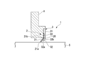
- FIG. 2A is a schematic enlarged sectional view including a part of the sealing mechanism 1 at normal temperature
- FIG. 2B is a schematic enlarged sectional view including a part of the sealing mechanism 1 at a cryogenic temperature.
- a gap is formed between the stopper 32 and the root portion 21b of the seal lip 2 at room temperature.
- the seal lip 2 is deformed by the stopper 32 so that the axis L1 of the seal lip 2 coincides with the axis LS of the shaft S. Is supported.
- the seal mechanism 1 of the present embodiment as described above is separated from the peripheral surface of the shaft S between the shaft 21 and the root portion 21b of the seal lip 2 (a portion excluding the edge portion 21a that directly contacts the shaft S).
- a stopper 32 is provided. Such a stopper 32 is provided in a housing H provided around the shaft S, and abuts against the seal lip 2 during cooling. As a result, the seal lip 2 contracts while being supported by the stopper 32, and the position of the seal lip 2 in the contraction process is defined. Therefore, the stopper 32 enables the axis L1 of the seal lip 2 that contracts to coincide with the axis LS of the shaft S. Therefore, according to the seal mechanism 1 of the present embodiment, it is possible to perform a good seal by matching the axis L1 of the seal lip 2 and the axis LS of the shaft S even at an extremely low temperature.
- the stopper 32 is provided in an annular shape around the axis LS of the shaft S. For this reason, no matter how the seal lip 2 contracts, the axis L1 of the seal lip 2 and the axis LS of the shaft S are more reliably matched by the contact between the stopper 32 and the seal lip 2. Is possible.
- the stopper 32 is formed of the same material as the housing H. For this reason, the stopper 32 and the housing H are similarly contracted during cooling, and the relative positional relationship of the stopper 32 with respect to the housing H does not change. Therefore, even during cooling, a change in the relative positional relationship of the stopper 32 with respect to the axis LS of the shaft S is prevented, and the axis L1 of the seal lip 2 and the axis LS of the shaft S can be matched more reliably. .
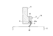
- 3A and 3B are schematic enlarged sectional views including a part of the seal mechanism 1A of the present embodiment.
- 3A is a schematic enlarged cross-sectional view including a part of the sealing mechanism 1 at normal temperature
- FIG. 3B is a schematic enlarged cross-sectional view including a part of the sealing mechanism 1 at cryogenic temperature.
- the seal mechanism 1A includes a mounting part 3 that does not have the stopper 32 described in the first embodiment, a seal lip 4 that has a bent portion 41, and a housing H.
- a stopper 5 provided integrally therewith is provided.
- the seal lip 4 has an annular shape similar to that of the seal lip 2 of the first embodiment, and is arranged so that the inner edge 42 abuts the outer peripheral surface of the shaft S.
- the bent portion 41 of the seal lip 4 is provided at the end portion on the outer peripheral side of the seal lip 4 that is located farther from the shaft S than the edge portion 42 that contacts the shaft S, and is disposed so as to face the shaft S side.
- the contact surface 41a is provided.
- Such a seal lip 4 is formed of the same material as the seal lip 2 of the first embodiment.
- the stopper 5 is made of the same material as the housing H, and is disposed between the bent portion 41 and the shaft S.
- the stopper 5 has an annular shape having a smaller diameter than the contact surface 41a of the bent portion 41, and the outer peripheral surface thereof is disposed to face the contact surface 41a of the bent portion 41 as shown in FIG. 3A. .
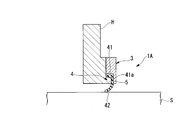
- FIG. 3B such a stopper 5 is in contact with the contact surface 41a of the seal lip 4 whose diameter is reduced during cooling so that the axis of the seal lip 4 coincides with the axis of the shaft S. Guides the deformation of the lip 4 when the diameter is reduced.
- the axis of the contracting seal lip 4 can be made to coincide with the axis of the shaft S by the stopper 5 as in the sealing mechanism of the first embodiment. Therefore, according to the seal mechanism 1A of the present embodiment, it is possible to perform a good seal by matching the axis of the seal lip 4 and the axis of the shaft S even at an extremely low temperature.
- the contact surface 41a of the bent portion 41 faces the shaft S side so as to be orthogonal to the radial direction of the shaft S.
- the stopper 5 can be brought into contact with the seal lip 4 from the surface facing the direction). Therefore, the seal lip 4 can be reliably guided.
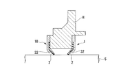
- FIG. 4A and 4B are enlarged sectional views schematically showing modifications of the present invention.
- 4A is an enlarged cross-sectional view at normal temperature
- FIG. 4B is an enlarged cross-sectional view at extremely low temperature.
- a sealing mechanism 1B whose shape is reversed from that of the sealing mechanism 1 may be installed on the higher pressure side of the sealing mechanism 1 of the first embodiment.
- a fluid having a higher sealing property can be obtained by sealing a fluid such as a flushing gas between the seal mechanism 1 and the seal mechanism 1A.
Abstract
This seal mechanism (1) is provided with an annular resin seal lip (2) which is disposed coaxially with respect to a shaft (S), and which is brought into contact with the peripheral surface of the shaft. The seal mechanism (1) is further provided with a stopper (3) which is provided to a metal housing (H) surrounding the shaft, which is disposed between the shaft and a portion of the seal lip other than an edge portion in direct contact with the shaft, and which is disposed at a distance from the peripheral surface of the shaft. The stopper comprises a material having a lower thermal expansion coefficient than the material forming the seal lip. Furthermore, as a result of the stopper being brought into contact with the seal lip which reduces in diameter when cooled, the axis of the seal lip is made to correspond with the axis (LS) of the shaft.
Description
本発明は、シール機構に関する。
本願は、2014年2月21日に日本に出願された特願2014-31553号に基づき優先権を主張し、その内容をここに援用する。 The present invention relates to a sealing mechanism.
This application claims priority based on Japanese Patent Application No. 2014-31553 for which it applied to Japan on February 21, 2014, and uses the content here.
本願は、2014年2月21日に日本に出願された特願2014-31553号に基づき優先権を主張し、その内容をここに援用する。 The present invention relates to a sealing mechanism.
This application claims priority based on Japanese Patent Application No. 2014-31553 for which it applied to Japan on February 21, 2014, and uses the content here.
従来から、例えば特許文献1及び特許文献2に示すようなシールリップを用いたシール機構が用いられている。このようなシール機構では、環状のシールリップの内側の縁部がシャフトの周面に当接された状態で配置され、シャフトが回転するときにはシールリップがシャフトに対して摺動した状態でシールを行う。
Conventionally, for example, a seal mechanism using a seal lip as shown in Patent Document 1 and Patent Document 2 has been used. In such a seal mechanism, the inner edge of the annular seal lip is arranged in contact with the peripheral surface of the shaft, and when the shaft rotates, the seal lip slides against the shaft. Do.
一方、ロケットエンジン用のターボポンプ等では、極低温(例えば、-200°C程度)となるため、シールリップを用いたシール機構は用いられていない。これは、一般的にシールリップがエラストマ等の極低温において脆くなる材料によって形成されていることによる。ただし、近年の技術の進歩により、極低温においても信頼性の高い樹脂材料が開発されてきており、このような材料からなるシールリップを用いたシール機構を上述のような極低温の環境で使用する装置に用いることが今後考えられる。
On the other hand, since turbo pumps for rocket engines are extremely low temperature (for example, about -200 ° C), a seal mechanism using a seal lip is not used. This is because the seal lip is generally formed of a material that becomes brittle at an extremely low temperature, such as an elastomer. However, due to advances in technology in recent years, highly reliable resin materials have been developed even at extremely low temperatures, and a seal mechanism using a seal lip made of such materials is used in the above-mentioned cryogenic environment. It is considered that it will be used in future.
しかしながら、極低温においても信頼性が高い材料であっても、樹脂材であることから、金属製のシャフトや同様に金属製のハウジングに対して熱膨張係数が大きい。つまり、常温から極低温となったときの収縮率は、樹脂製のシールリップと、金属製のシャフトやハウジングとで大きく異なる。このような場合に、シールリップがシャフトと同軸状態を維持して収縮するには、シールリップが軸周りに均等な力で保持される必要があるが、当然に存在する組み付け誤差等によって、シールリップは必ずしも軸周りに均等な力で保持されない。このため、常温において、シールリップとシャフトとの芯出しが正確に行われていたとしても、極低温においてシールリップの軸とシャフトの軸とが一致していない可能性がある。シールリップの軸とシャフトの軸とがずれた場合には、シールリップのシャフトに対する押圧力分布に、シールリップの周方向における偏りが生じ、その結果、シャフトの回転抵抗が増加したり、シール性が悪化したりする可能性がある。
However, even if the material is highly reliable even at an extremely low temperature, it is a resin material, and therefore has a larger thermal expansion coefficient than that of a metal shaft or a metal housing. That is, the shrinkage rate when the temperature is changed from room temperature to extremely low temperature is greatly different between the resin seal lip and the metal shaft or housing. In such a case, in order for the seal lip to shrink while maintaining the coaxial condition with the shaft, the seal lip needs to be held with an equal force around the axis. The lip is not necessarily held around the axis with equal force. For this reason, even if the centering of the seal lip and the shaft is accurately performed at room temperature, the shaft of the seal lip and the shaft of the shaft may not coincide with each other at an extremely low temperature. If the shaft of the seal lip and the shaft of the shaft deviate, the pressure distribution of the seal lip against the shaft will be biased in the circumferential direction of the seal lip. As a result, the rotational resistance of the shaft will increase and the sealing performance May get worse.
本発明は、上述する問題点に鑑みてなされたもので、シールリップを有すると共に極低温で用いられるシール機構において、極低温であってもシールリップの軸とシャフトの軸とを一致させることで良好なシールを行うことを目的とする。
The present invention has been made in view of the above-described problems. In a seal mechanism having a seal lip and used at an extremely low temperature, the shaft of the seal lip and the shaft of the shaft are made to coincide even at an extremely low temperature. The purpose is to provide a good seal.
本発明は、上記課題を解決するための手段として、以下の構成を採用する。
The present invention adopts the following configuration as means for solving the above-described problems.
本発明に係る第1の態様は、 シャフトに対して同軸に配置されると共に上記シャフトの周面に当接する環状かつ樹脂製のシールリップを備えるシール機構であって、上記シャフトを囲う金属製のハウジングに設けられると共に、上記シールリップの上記シャフトと直接当接する縁部を除く箇所と上記シャフトとの間に上記シャフトの周面と離間して配置されるストッパを備え、上記ストッパが、上記シールリップの形成材料よりも熱膨張係数が小さい材料からなり、冷却時に縮径する上記シールリップと当接することにより、上記シールリップの軸を上記シャフトの軸と一致させる。
According to a first aspect of the present invention, there is provided a seal mechanism including an annular and resin seal lip that is arranged coaxially with respect to a shaft and abuts on a peripheral surface of the shaft, and is made of a metal that surrounds the shaft. A stopper provided on the housing and spaced apart from a peripheral surface of the shaft between a portion of the seal lip excluding an edge portion that directly contacts the shaft and the shaft, and the stopper includes the seal The shaft of the seal lip is made to coincide with the shaft of the shaft by coming into contact with the seal lip, which is made of a material having a smaller thermal expansion coefficient than that of the material for forming the lip and is reduced in diameter upon cooling.
本発明に係る第2の態様は、上記第1の態様において、上記ストッパが、上記シャフトの軸を中心として環状に設けられている。
In a second aspect according to the present invention, in the first aspect, the stopper is provided in an annular shape around the axis of the shaft.
本発明に係る第3の態様は、上記第1または第2の態様において、上記ストッパが、上記ハウジングと同一の材料によって形成されている。
In a third aspect according to the present invention, in the first or second aspect, the stopper is formed of the same material as the housing.
本発明に係る第4の態様は、上記第1~第3のいずれかの態様において、上記シールリップが、上記縁部よりも上記シャフトから離間した位置に設けられると共に上記シャフト側を向く当接面を有する屈曲部を有し、上記ストッパが、上記屈曲部の上記当接面と上記シャフトとの間に配置されている。
According to a fourth aspect of the present invention, in any one of the first to third aspects, the seal lip is provided at a position farther from the shaft than the edge and contacts the shaft side. A bent portion having a surface is provided, and the stopper is disposed between the contact surface of the bent portion and the shaft.
本発明に係るシール機構は、シールリップのシャフトと直接当接する縁部を除く箇所とシャフトとの間にシャフトの周面と離間して配置されるストッパを備えている。このようなストッパは、シャフトの周囲に設けられたハウジングに設けられており、冷却時にシールリップに当接する。この結果、シールリップはストッパに支えられた状態で収縮することになり、シールリップの収縮過程における位置を規定することができる。よって、ストッパによって、収縮するシールリップの軸をシャフトの軸と一致させることが可能となる。したがって、本発明によれば、シールリップを有すると共に極低温で用いられるシール機構において、極低温であってもシールリップの軸とシャフトの軸とを一致させることで良好なシールを行うことが可能となる。
The seal mechanism according to the present invention includes a stopper disposed apart from the peripheral surface of the shaft between the shaft and a portion other than the edge portion that directly contacts the shaft of the seal lip. Such a stopper is provided in a housing provided around the shaft, and contacts the seal lip during cooling. As a result, the seal lip contracts while being supported by the stopper, and the position of the seal lip in the contraction process can be defined. Thus, the stopper allows the contracting seal lip axis to coincide with the shaft axis. Therefore, according to the present invention, in a seal mechanism having a seal lip and used at a cryogenic temperature, it is possible to achieve a good seal by matching the shaft of the seal lip and the shaft of the shaft even at a cryogenic temperature. It becomes.
以下、図面を参照して、本発明に係るシール機構の実施形態について説明する。なお、以下の図面において、各部材を認識可能な大きさとするために、各部材の縮尺を適宜変更している。
Hereinafter, an embodiment of a seal mechanism according to the present invention will be described with reference to the drawings. In the following drawings, the scale of each member is appropriately changed in order to make each member a recognizable size.
(第1実施形態)
図1Aは、本実施形態のシール機構1の概略構成を模式的に示す断面図である。本実施形態のシール機構1は、図1Aに示すように、シャフトSとシャフトSを囲うハウジングHとを有すると共に極低温にて用いられる装置(例えば、ロケットエンジン用ターボポンプ)に組み込まれて用いられる。なお、シャフトS及びハウジングHは、例えば、ニッケル基合金やステンレス鋼によって形成された金属製の部材である。また、図1Aにおいては、シャフトS及びハウジングHの一部のみを図示している。 (First embodiment)
FIG. 1A is a cross-sectional view schematically showing a schematic configuration of theseal mechanism 1 of the present embodiment. As shown in FIG. 1A, the seal mechanism 1 of the present embodiment is incorporated in a device (for example, a rocket engine turbo pump) that has a shaft S and a housing H that surrounds the shaft S and is used at a cryogenic temperature. It is done. The shaft S and the housing H are metal members formed of, for example, a nickel base alloy or stainless steel. In FIG. 1A, only a part of the shaft S and the housing H is shown.
図1Aは、本実施形態のシール機構1の概略構成を模式的に示す断面図である。本実施形態のシール機構1は、図1Aに示すように、シャフトSとシャフトSを囲うハウジングHとを有すると共に極低温にて用いられる装置(例えば、ロケットエンジン用ターボポンプ)に組み込まれて用いられる。なお、シャフトS及びハウジングHは、例えば、ニッケル基合金やステンレス鋼によって形成された金属製の部材である。また、図1Aにおいては、シャフトS及びハウジングHの一部のみを図示している。 (First embodiment)
FIG. 1A is a cross-sectional view schematically showing a schematic configuration of the
このようなシール機構1は、図1Aに示すように、シールリップ2と、取付部品3とを備えている。図1Bは、シールリップ2の斜視図である。図1Bに示すように、シールリップ2は、軸L1を中心とする環状の部材であり、軸L1と直交する方向における略中央部にて屈曲されている。
Such a seal mechanism 1 includes a seal lip 2 and an attachment part 3 as shown in FIG. 1A. FIG. 1B is a perspective view of the seal lip 2. As shown in FIG. 1B, the seal lip 2 is an annular member centered on the axis L1, and is bent at a substantially central portion in a direction orthogonal to the axis L1.
屈曲された箇所(以下、屈曲箇所20と称する)の内側に位置する内側部21は、軸L1側の縁部21aが高圧側(図1Aにおいてシール機構1の左側)に位置し、屈曲箇所20側の根元部21bが低圧側(図1Aにおいてシール機構1の右側)に位置するテーパ形状とされている。つまり、内側部21の形状は、高圧側に向けて窄むように設定されている。このような内側部21の縁部21aは、図1Aに示すようにシャフトSの外周面に対して当接されており、シャフトSが回転したときにはシャフトSに対して摺接される。
The inner portion 21 located inside the bent portion (hereinafter referred to as the bent portion 20) has an edge portion 21a on the axis L1 side located on the high pressure side (left side of the seal mechanism 1 in FIG. 1A), and the bent portion 20 The side root portion 21b is tapered such that it is located on the low pressure side (the right side of the seal mechanism 1 in FIG. 1A). That is, the shape of the inner portion 21 is set so as to be narrowed toward the high-pressure side. The edge portion 21a of the inner portion 21 is in contact with the outer peripheral surface of the shaft S as shown in FIG. 1A, and is in sliding contact with the shaft S when the shaft S rotates.
屈曲箇所20の外側に位置する外側部22は、内側部21の外側に配置された部位であり、軸L1に対して直交する表裏面を有する薄板状の環状部である。このような外側部22は、図1Aに示すように、取付部品3とハウジングHとに狭持される部位であり、ハウジングHに対して取り付けられる取付部として機能する。
The outer portion 22 located outside the bent portion 20 is a portion disposed outside the inner portion 21, and is a thin plate-like annular portion having front and back surfaces orthogonal to the axis L1. As shown in FIG. 1A, such an outer portion 22 is a portion that is sandwiched between the attachment component 3 and the housing H, and functions as an attachment portion that is attached to the housing H.
このシールリップ2は、極低温において脆くなり難い樹脂材料によって形成された樹脂製の部材である。例えば、このようなシールリップ2の材料としては、ポリテトラフルオロエチレン(PTFE)、ポリエーテルエーテルケトン(PEEK)等が挙げられる。また、ポリテトラフルオロエチレンをベース材としてポリエーテルエーテルケトンを添加した材料や、ポリエーテルエーテルケトンをベース材としてポリテトラフルオロエチレン(その他フッ素系樹脂でも良い)を添加した材料を用いてシールリップ2を形成することもできる。
The seal lip 2 is a resin member formed of a resin material that is not easily brittle at extremely low temperatures. For example, examples of the material for the seal lip 2 include polytetrafluoroethylene (PTFE), polyether ether ketone (PEEK), and the like. Seal lip 2 using a material in which polyetheretherketone is added using polytetrafluoroethylene as a base material, or a material in which polytetrafluoroethylene (other fluororesin may be used) is added using polyetheretherketone as a base material. Can also be formed.
上述の材料は、どれも樹脂材料であり、シャフトSやハウジングHを形成する金属材料よりも熱膨張係数が高い。このため、シールリップ2は、常温から極低温に冷却されたときには、シャフトSやハウジングHよりも大きく収縮する。
The above-mentioned materials are all resin materials, and have a higher thermal expansion coefficient than the metal materials forming the shaft S and the housing H. For this reason, the seal lip 2 contracts more greatly than the shaft S and the housing H when cooled from normal temperature to extremely low temperature.
このようなシールリップ2は、常温において、軸L1がシャフトSの軸LS(図1A参照)と重なるように、ハウジングHに取り付けられる。つまり、シールリップ2は、シャフトSに対して同軸をなすように配置されている。
Such a seal lip 2 is attached to the housing H so that the axis L1 overlaps the axis LS (see FIG. 1A) of the shaft S at room temperature. That is, the seal lip 2 is disposed so as to be coaxial with the shaft S.
取付部品3は、シールリップ2をハウジングHに対して取り付けると共に、冷却時に収縮するシールリップ2の芯出しを行う部品であり、ベース部31と、ストッパ32とを備えている。
The attachment part 3 is a part that attaches the seal lip 2 to the housing H and performs centering of the seal lip 2 that contracts during cooling, and includes a base portion 31 and a stopper 32.
ベース部31は、シャフトSの軸LSに沿った方向から見て、シールリップ2の外側部22と略同一の大きさとされた環状のブロック状の部位である。このベース部31は、図1Aに示すように、シールリップ2の外側部22を挟み込むようにしてハウジングHに対して不図示のボルト等によって固定されている。
The base portion 31 is an annular block-shaped portion having substantially the same size as the outer portion 22 of the seal lip 2 when viewed from the direction along the axis LS of the shaft S. As shown in FIG. 1A, the base portion 31 is fixed to the housing H with a bolt (not shown) or the like so as to sandwich the outer portion 22 of the seal lip 2.
ストッパ32は、ベース部31よりもシャフトSの軸LS側に設けられており、軸LS側の先端32a(図2A及びB参照)がシールリップ2の内側部21寄りに位置し、根元部32b(図2A及びB参照)が先端32aよりもシールリップ2から遠方に位置するテーパ形状とされている。つまり、ストッパ32の形状は、シールリップ2側に向けて窄むように設定されている。このようなストッパ32は、先端32aがシールリップ2の根元部21bとシャフトSとの間に入り込むように配置されている。
The stopper 32 is provided closer to the shaft LS side of the shaft S than the base portion 31, and the tip 32a (see FIGS. 2A and 2B) on the shaft LS side is located closer to the inner portion 21 of the seal lip 2, and the root portion 32b. (Refer to FIGS. 2A and 2B) has a tapered shape located farther from the seal lip 2 than the tip 32a. That is, the shape of the stopper 32 is set so as to narrow toward the seal lip 2 side. Such a stopper 32 is arranged so that the tip 32 a enters between the root 21 b of the seal lip 2 and the shaft S.
つまり、このようストッパ32は、シールリップ2の根元部21b(シャフトSと直接当接する縁部21aを除く箇所)とシャフトSとの間にシャフトSの外周面と離間して配置されており、シャフトSの軸LSを中心として環状に設けられている。
That is, the stopper 32 is disposed between the shaft S and the base portion 21b of the seal lip 2 (a portion excluding the edge portion 21a that directly contacts the shaft S) and the shaft S. The shaft S is provided in an annular shape around the axis LS.
また、ストッパ32は、シールリップ2の形成材料よりも熱膨張係数が小さい材料からなり、本実施形態においては、ハウジングHと同一の材料から形成されている。つまり、ハウジングHがニッケル基合金によって形成されている場合は、ストッパ32もニッケル基合金によって形成される。なお、ベース部31もストッパ32と同一の材料によって形成されている。これらのベース部31とストッパ32とが一体化されて1つの取付部品3が形成されている。このような取付部品3がハウジングHに対して固定されることにより、ハウジングHに対する所定の位置にストッパ32が設けられている。
Further, the stopper 32 is made of a material having a smaller thermal expansion coefficient than the material for forming the seal lip 2, and is made of the same material as the housing H in the present embodiment. That is, when the housing H is formed of a nickel base alloy, the stopper 32 is also formed of a nickel base alloy. Note that the base portion 31 is also formed of the same material as the stopper 32. The base part 31 and the stopper 32 are integrated to form one attachment part 3. By fixing the mounting part 3 to the housing H, a stopper 32 is provided at a predetermined position with respect to the housing H.
このようなストッパ32は、冷却時に縮径するシールリップ2の根元部21bと当接することによって、シールリップ2の軸L1がシャフトSの軸LSと一致するように、シールリップ2の縮径時における変形をガイドする。
Such a stopper 32 is in contact with the base portion 21b of the seal lip 2 whose diameter is reduced during cooling, so that the axis L1 of the seal lip 2 coincides with the axis LS of the shaft S when the diameter of the seal lip 2 is reduced. Guide the deformation in.
図2Aは常温時のシール機構1の一部を含む模式的な拡大断面図であり、図2Bは極低温時のシール機構1の一部を含む模式的な拡大断面図である。図2Aに示すように、常温時には、ストッパ32とシールリップ2の根元部21bとの間には隙間が形成されている。シール機構1が冷却されて、ハウジングH、シャフトS及びストッパ32に対して、シールリップ2が大きく収縮すると、図2Bに示すように、シールリップ2の根元部21bがストッパ32に当接する。ここでストッパ32の形状がシャフトSの軸LSを中心とする環状とされていることから、ストッパ32によって、シールリップ2の軸L1がシャフトSの軸LSと一致するようにシールリップ2の変形がサポートされる。
FIG. 2A is a schematic enlarged sectional view including a part of the sealing mechanism 1 at normal temperature, and FIG. 2B is a schematic enlarged sectional view including a part of the sealing mechanism 1 at a cryogenic temperature. As shown in FIG. 2A, a gap is formed between the stopper 32 and the root portion 21b of the seal lip 2 at room temperature. When the seal mechanism 1 is cooled and the seal lip 2 contracts greatly with respect to the housing H, the shaft S, and the stopper 32, the root portion 21b of the seal lip 2 contacts the stopper 32 as shown in FIG. 2B. Here, since the shape of the stopper 32 is annular around the axis LS of the shaft S, the seal lip 2 is deformed by the stopper 32 so that the axis L1 of the seal lip 2 coincides with the axis LS of the shaft S. Is supported.
以上のような本実施形態のシール機構1は、シールリップ2の根元部21b(シャフトSと直接当接する縁部21aを除く箇所)とシャフトSとの間にシャフトSの周面と離間して配置されるストッパ32を備えている。このようなストッパ32は、シャフトSの周囲に設けられたハウジングHに設けられており、冷却時にシールリップ2に当接する。この結果、シールリップ2はストッパ32に支えられた状態で収縮することになり、シールリップ2の収縮過程における位置が規定される。よって、ストッパ32によって、収縮するシールリップ2の軸L1をシャフトSの軸LSと一致させることが可能となる。したがって、本実施形態のシール機構1によれば、極低温であってもシールリップ2の軸L1とシャフトSの軸LSとを一致させることで良好なシールを行うことが可能となる。
The seal mechanism 1 of the present embodiment as described above is separated from the peripheral surface of the shaft S between the shaft 21 and the root portion 21b of the seal lip 2 (a portion excluding the edge portion 21a that directly contacts the shaft S). A stopper 32 is provided. Such a stopper 32 is provided in a housing H provided around the shaft S, and abuts against the seal lip 2 during cooling. As a result, the seal lip 2 contracts while being supported by the stopper 32, and the position of the seal lip 2 in the contraction process is defined. Therefore, the stopper 32 enables the axis L1 of the seal lip 2 that contracts to coincide with the axis LS of the shaft S. Therefore, according to the seal mechanism 1 of the present embodiment, it is possible to perform a good seal by matching the axis L1 of the seal lip 2 and the axis LS of the shaft S even at an extremely low temperature.
また、本実施形態のシール機構1においては、ストッパ32が、シャフトSの軸LSを中心として環状に設けられている。このため、シールリップ2がどのように収縮した場合であっても、ストッパ32とシールリップ2との当接により、より確実にシールリップ2の軸L1とシャフトSの軸LSとを一致させることが可能となる。
Further, in the seal mechanism 1 of the present embodiment, the stopper 32 is provided in an annular shape around the axis LS of the shaft S. For this reason, no matter how the seal lip 2 contracts, the axis L1 of the seal lip 2 and the axis LS of the shaft S are more reliably matched by the contact between the stopper 32 and the seal lip 2. Is possible.
また、本実施形態のシール機構1においては、ストッパ32がハウジングHと同一の材料によって形成されている。このため、冷却時にストッパ32とハウジングHとが同様に収縮することになり、ハウジングHに対するストッパ32の相対的な位置関係が変化しない。よって、冷却時においてもストッパ32のシャフトSの軸LSに対する相対的な位置関係の変化が防止され、より確実にシールリップ2の軸L1とシャフトSの軸LSとを一致させることが可能となる。
Further, in the seal mechanism 1 of this embodiment, the stopper 32 is formed of the same material as the housing H. For this reason, the stopper 32 and the housing H are similarly contracted during cooling, and the relative positional relationship of the stopper 32 with respect to the housing H does not change. Therefore, even during cooling, a change in the relative positional relationship of the stopper 32 with respect to the axis LS of the shaft S is prevented, and the axis L1 of the seal lip 2 and the axis LS of the shaft S can be matched more reliably. .
(第2実施形態)
次に、本発明の第2実施形態について説明する。なお、本実施形態において、上記第1実施形態と同様の部分については、その説明を省略する。 (Second Embodiment)
Next, a second embodiment of the present invention will be described. In the present embodiment, the description of the same parts as those in the first embodiment is omitted.
次に、本発明の第2実施形態について説明する。なお、本実施形態において、上記第1実施形態と同様の部分については、その説明を省略する。 (Second Embodiment)
Next, a second embodiment of the present invention will be described. In the present embodiment, the description of the same parts as those in the first embodiment is omitted.
図3A及びBは、本実施形態のシール機構1Aの一部を含む模式的な拡大断面図である。なお、図3Aは、常温時のシール機構1の一部を含む模式的な拡大断面図であり、図3Bは極低温時のシール機構1の一部を含む模式的な拡大断面図である。
3A and 3B are schematic enlarged sectional views including a part of the seal mechanism 1A of the present embodiment. 3A is a schematic enlarged cross-sectional view including a part of the sealing mechanism 1 at normal temperature, and FIG. 3B is a schematic enlarged cross-sectional view including a part of the sealing mechanism 1 at cryogenic temperature.
これらの図に示すように、本実施形態のシール機構1Aは、上記第1実施形態において説明したストッパ32を有していない取付部品3と、屈曲部41を有するシールリップ4と、ハウジングHに対して一体的に設けられたストッパ5とを備えている。
As shown in these drawings, the seal mechanism 1A according to the present embodiment includes a mounting part 3 that does not have the stopper 32 described in the first embodiment, a seal lip 4 that has a bent portion 41, and a housing H. On the other hand, a stopper 5 provided integrally therewith is provided.
シールリップ4は、上記第1実施形態のシールリップ2と同様の環状とされており、内側の縁部42がシャフトSの外周面に当接するように配置されている。シールリップ4の屈曲部41は、シャフトSに当接する縁部42よりもシャフトSから離間した位置であるシールリップ4の外周側の端部に設けられており、シャフトS側を向くように配置される当接面41aを有している。このようなシールリップ4は、第1実施形態のシールリップ2と同様の材料によって形成されている。
The seal lip 4 has an annular shape similar to that of the seal lip 2 of the first embodiment, and is arranged so that the inner edge 42 abuts the outer peripheral surface of the shaft S. The bent portion 41 of the seal lip 4 is provided at the end portion on the outer peripheral side of the seal lip 4 that is located farther from the shaft S than the edge portion 42 that contacts the shaft S, and is disposed so as to face the shaft S side. The contact surface 41a is provided. Such a seal lip 4 is formed of the same material as the seal lip 2 of the first embodiment.
ストッパ5は、ハウジングHと同一の材料から形成されており、屈曲部41とシャフトSとの間に配置されている。このストッパ5は、屈曲部41の当接面41aよりも径の小さな環状とされており、図3Aに示すように、外周面が屈曲部41の当接面41aに対向して配置されている。このようなストッパ5は、図3Bに示すように、冷却時に縮径するシールリップ4の当接面41aと当接することによって、シールリップ4の軸がシャフトSの軸と一致するように、シールリップ4の縮径時における変形をガイドする。
The stopper 5 is made of the same material as the housing H, and is disposed between the bent portion 41 and the shaft S. The stopper 5 has an annular shape having a smaller diameter than the contact surface 41a of the bent portion 41, and the outer peripheral surface thereof is disposed to face the contact surface 41a of the bent portion 41 as shown in FIG. 3A. . As shown in FIG. 3B, such a stopper 5 is in contact with the contact surface 41a of the seal lip 4 whose diameter is reduced during cooling so that the axis of the seal lip 4 coincides with the axis of the shaft S. Guides the deformation of the lip 4 when the diameter is reduced.
このような本実施形態のシール機構1Aにおいても、上記第1実施形態のシール機構と同様に、ストッパ5によって、収縮するシールリップ4の軸をシャフトSの軸と一致させることが可能となる。したがって、本実施形態のシール機構1Aによれば、極低温であってもシールリップ4の軸とシャフトSの軸とを一致させることで良好なシールを行うことが可能となる。
In the sealing mechanism 1A of this embodiment as well, the axis of the contracting seal lip 4 can be made to coincide with the axis of the shaft S by the stopper 5 as in the sealing mechanism of the first embodiment. Therefore, according to the seal mechanism 1A of the present embodiment, it is possible to perform a good seal by matching the axis of the seal lip 4 and the axis of the shaft S even at an extremely low temperature.
さらに、本実施形態のシール機構1Aにおいては、屈曲部41の当接面41aがシャフトSの半径方向と直交するようにシャフトS側を向いているため、収縮方向の正面(シールリップ4の収縮方向と対向する面)からストッパ5をシールリップ4に対して当接させることができる。よって、確実にシールリップ4をガイドすることが可能となる。
Furthermore, in the seal mechanism 1A of the present embodiment, the contact surface 41a of the bent portion 41 faces the shaft S side so as to be orthogonal to the radial direction of the shaft S. The stopper 5 can be brought into contact with the seal lip 4 from the surface facing the direction). Therefore, the seal lip 4 can be reliably guided.
以上、添付図面を参照しながら本発明の好適な実施形態について説明したが、本発明は、上記実施形態に限定されないことは言うまでもない。上述した実施形態において示した各構成部材の諸形状や組み合わせ等は一例であって、本発明の趣旨から逸脱しない範囲において設計要求等に基づき種々変更可能である。
The preferred embodiments of the present invention have been described above with reference to the accompanying drawings, but the present invention is not limited to the above-described embodiments. Various shapes, combinations, and the like of the constituent members shown in the above-described embodiments are examples, and various modifications can be made based on design requirements and the like without departing from the spirit of the present invention.
図4A及びBは、本発明の変形例を模式的に示す拡大断面図である。図4Aは、常温時の拡大断面図であり、図4Bは極低温時の拡大断面図である。これらの図に示すように、上記第1実施形態のシール機構1のさらに高圧側に、シール機構1と形状が反転されたシール機構1Bを設置するようにしても良い。このような場合には、これらのシール機構1とシール機構1Aとの間にフラッシングガス等の流体を封入してよりシール性の高い構造とすることができる。
4A and 4B are enlarged sectional views schematically showing modifications of the present invention. 4A is an enlarged cross-sectional view at normal temperature, and FIG. 4B is an enlarged cross-sectional view at extremely low temperature. As shown in these drawings, a sealing mechanism 1B whose shape is reversed from that of the sealing mechanism 1 may be installed on the higher pressure side of the sealing mechanism 1 of the first embodiment. In such a case, a fluid having a higher sealing property can be obtained by sealing a fluid such as a flushing gas between the seal mechanism 1 and the seal mechanism 1A.
シールリップを有すると共に極低温で用いられるシール機構において、極低温であってもシールリップの軸とシャフトの軸とを一致させることで良好なシールを行うことが可能となる。
In a seal mechanism having a seal lip and being used at a very low temperature, it is possible to perform a good seal by matching the shaft of the seal lip and the shaft of the shaft even at a very low temperature.
1、1A、1B シール機構
2、4 シールリップ
3 取付部品
5、32 ストッパ
20 屈曲箇所
21 内側部
21a、42 縁部
21b 根元部
22 外側部
31 ベース部
32a 先端
32b 根元部
41 屈曲部
41a 当接面
H ハウジング
L1 シールリップの軸
LS シャフトの軸
S シャフト 1, 1A, 1B Seal mechanism 2, 4 Seal lip 3 Attachment parts 5, 32 Stopper 20 Bent part 21 Inner part 21a, 42 Edge part 21b Root part 22 Outer part 31 Base part 32a Tip 32b Root part 41 Bent part 41a Contact Surface H Housing L1 Seal lip axis LS Shaft axis S Shaft
2、4 シールリップ
3 取付部品
5、32 ストッパ
20 屈曲箇所
21 内側部
21a、42 縁部
21b 根元部
22 外側部
31 ベース部
32a 先端
32b 根元部
41 屈曲部
41a 当接面
H ハウジング
L1 シールリップの軸
LS シャフトの軸
S シャフト 1, 1A,
Claims (8)
- シャフトに対して同軸に配置されると共に前記シャフトの周面に当接する環状かつ樹脂製のシールリップを備えるシール機構であって、
前記シャフトを囲う金属製のハウジングに設けられると共に、前記シールリップの前記シャフトと直接当接する縁部を除く箇所と前記シャフトとの間に前記シャフトの周面と離間して配置されるストッパを備え、
前記ストッパは、前記シールリップの形成材料よりも熱膨張係数が小さい材料からなり、冷却時に縮径する前記シールリップと当接することにより、前記シールリップの軸を前記シャフトの軸と一致させる、
シール機構。 A seal mechanism that is arranged coaxially with respect to the shaft and includes an annular and resin seal lip that abuts against the peripheral surface of the shaft;
A stopper provided on a metal housing surrounding the shaft and spaced apart from a peripheral surface of the shaft between a portion of the seal lip excluding an edge portion directly contacting the shaft and the shaft; ,
The stopper is made of a material having a smaller thermal expansion coefficient than the material for forming the seal lip, and abuts on the seal lip whose diameter is reduced during cooling, thereby matching the axis of the seal lip with the axis of the shaft.
Seal mechanism. - 前記ストッパが、前記シャフトの軸を中心として環状に設けられている請求項1に記載のシール機構。 The seal mechanism according to claim 1, wherein the stopper is provided in an annular shape around the axis of the shaft.
- 前記ストッパが、前記ハウジングと同一の材料によって形成されている請求項1に記載のシール機構。 The seal mechanism according to claim 1, wherein the stopper is made of the same material as the housing.
- 前記ストッパが、前記ハウジングと同一の材料によって形成されている請求項2に記載のシール機構。 The seal mechanism according to claim 2, wherein the stopper is made of the same material as the housing.
- 前記シールリップが、前記縁部よりも前記シャフトから離間した位置に設けられると共に前記シャフト側を向く当接面を有する屈曲部を有し、
前記ストッパが、前記屈曲部の前記当接面と前記シャフトとの間に配置されている請求項1に記載のシール機構。 The seal lip has a bent portion provided at a position farther from the shaft than the edge and having a contact surface facing the shaft;
The seal mechanism according to claim 1, wherein the stopper is disposed between the contact surface of the bent portion and the shaft. - 前記シールリップが、前記縁部よりも前記シャフトから離間した位置に設けられると共に前記シャフト側を向く当接面を有する屈曲部を有し、
前記ストッパが、前記屈曲部の前記当接面と前記シャフトとの間に配置されている請求項2に記載のシール機構。 The seal lip has a bent portion provided at a position farther from the shaft than the edge and having a contact surface facing the shaft;
The seal mechanism according to claim 2, wherein the stopper is disposed between the contact surface of the bent portion and the shaft. - 前記シールリップが、前記縁部よりも前記シャフトから離間した位置に設けられると共に前記シャフト側を向く当接面を有する屈曲部を有し、
前記ストッパが、前記屈曲部の前記当接面と前記シャフトとの間に配置されている請求項3に記載のシール機構。 The seal lip has a bent portion provided at a position farther from the shaft than the edge and having a contact surface facing the shaft;
The seal mechanism according to claim 3, wherein the stopper is disposed between the contact surface of the bent portion and the shaft. - 前記シールリップが、前記縁部よりも前記シャフトから離間した位置に設けられると共に前記シャフト側を向く当接面を有する屈曲部を有し、
前記ストッパが、前記屈曲部の前記当接面と前記シャフトとの間に配置されている請求項4に記載のシール機構。 The seal lip has a bent portion provided at a position farther from the shaft than the edge and having a contact surface facing the shaft;
The seal mechanism according to claim 4, wherein the stopper is disposed between the contact surface of the bent portion and the shaft.
Priority Applications (2)
| Application Number | Priority Date | Filing Date | Title |
|---|---|---|---|
| EP15751790.5A EP3109519B1 (en) | 2014-02-21 | 2015-02-23 | Seal mechanism |
| US15/198,413 US10323750B2 (en) | 2014-02-21 | 2016-06-30 | Seal mechanism |
Applications Claiming Priority (2)
| Application Number | Priority Date | Filing Date | Title |
|---|---|---|---|
| JP2014031553A JP6248692B2 (en) | 2014-02-21 | 2014-02-21 | Seal mechanism |
| JP2014-031553 | 2014-02-21 |
Related Child Applications (1)
| Application Number | Title | Priority Date | Filing Date |
|---|---|---|---|
| US15/198,413 Continuation US10323750B2 (en) | 2014-02-21 | 2016-06-30 | Seal mechanism |
Publications (1)
| Publication Number | Publication Date |
|---|---|
| WO2015125959A1 true WO2015125959A1 (en) | 2015-08-27 |
Family
ID=53878455
Family Applications (1)
| Application Number | Title | Priority Date | Filing Date |
|---|---|---|---|
| PCT/JP2015/055049 WO2015125959A1 (en) | 2014-02-21 | 2015-02-23 | Seal mechanism |
Country Status (4)
| Country | Link |
|---|---|
| US (1) | US10323750B2 (en) |
| EP (1) | EP3109519B1 (en) |
| JP (1) | JP6248692B2 (en) |
| WO (1) | WO2015125959A1 (en) |
Families Citing this family (2)
| Publication number | Priority date | Publication date | Assignee | Title |
|---|---|---|---|---|
| KR102139735B1 (en) * | 2018-07-02 | 2020-07-31 | 한국씰마스타주식회사 | One-stop seal for high temperature, high pressure applications |
| JP2020176673A (en) * | 2019-04-17 | 2020-10-29 | ナブテスコ株式会社 | Seal structure and seal |
Citations (3)
| Publication number | Priority date | Publication date | Assignee | Title |
|---|---|---|---|---|
| DE3221526A1 (en) * | 1982-06-08 | 1983-12-08 | Fa. Carl Freudenberg, 6940 Weinheim | Shaft sealing ring |
| JPH0177169U (en) * | 1987-11-12 | 1989-05-24 | ||
| JPH09303568A (en) * | 1996-05-17 | 1997-11-25 | Eagle Ind Co Ltd | Lip type seal |
Family Cites Families (8)
| Publication number | Priority date | Publication date | Assignee | Title |
|---|---|---|---|---|
| US3512789A (en) * | 1967-03-31 | 1970-05-19 | Charles L Tanner | Cryogenic face seal |
| US3997142A (en) * | 1975-04-21 | 1976-12-14 | Fmc Corporation | Pressure sensitive and temperature responsive rotary valve |
| JP3077410B2 (en) * | 1992-07-29 | 2000-08-14 | アイシン精機株式会社 | Turbocharger turbine housing |
| US5524846A (en) * | 1993-12-21 | 1996-06-11 | The Boeing Company | Fire protection system for airplanes |
| US6547250B1 (en) * | 2000-08-21 | 2003-04-15 | Westport Research Inc. | Seal assembly with two sealing mechanisms for providing static and dynamic sealing |
| KR101222621B1 (en) | 2004-12-20 | 2013-01-16 | 이글 고오교 가부시키가이샤 | Shaft sealing device |
| DE102007063216B4 (en) * | 2007-12-20 | 2018-04-26 | Elringklinger Ag | Method for producing a seal |
| WO2010061670A1 (en) | 2008-11-27 | 2010-06-03 | イーグル工業株式会社 | Lip seal |
-
2014
- 2014-02-21 JP JP2014031553A patent/JP6248692B2/en active Active
-
2015
- 2015-02-23 WO PCT/JP2015/055049 patent/WO2015125959A1/en active Application Filing
- 2015-02-23 EP EP15751790.5A patent/EP3109519B1/en active Active
-
2016
- 2016-06-30 US US15/198,413 patent/US10323750B2/en active Active
Patent Citations (3)
| Publication number | Priority date | Publication date | Assignee | Title |
|---|---|---|---|---|
| DE3221526A1 (en) * | 1982-06-08 | 1983-12-08 | Fa. Carl Freudenberg, 6940 Weinheim | Shaft sealing ring |
| JPH0177169U (en) * | 1987-11-12 | 1989-05-24 | ||
| JPH09303568A (en) * | 1996-05-17 | 1997-11-25 | Eagle Ind Co Ltd | Lip type seal |
Non-Patent Citations (1)
| Title |
|---|
| See also references of EP3109519A4 * |
Also Published As
| Publication number | Publication date |
|---|---|
| EP3109519A4 (en) | 2017-11-01 |
| US20160305553A1 (en) | 2016-10-20 |
| JP6248692B2 (en) | 2017-12-20 |
| EP3109519B1 (en) | 2019-09-18 |
| EP3109519A1 (en) | 2016-12-28 |
| JP2015155739A (en) | 2015-08-27 |
| US10323750B2 (en) | 2019-06-18 |
Similar Documents
| Publication | Publication Date | Title |
|---|---|---|
| KR102354320B1 (en) | Sealing device | |
| US9145973B2 (en) | Valve device | |
| US10077843B2 (en) | Division type mechanical seal | |
| JP6479456B2 (en) | Foil, foil bearing, and method of assembling foil bearing | |
| KR102244406B1 (en) | Labyrinth seal and labyrinth seal structure | |
| WO2015107760A1 (en) | Sealing device | |
| CN111512081B (en) | Fluid handling joint and fluid handling device | |
| JP6256117B2 (en) | Sealing device | |
| JP2009103264A (en) | Rotating shaft seal | |
| US20160178065A1 (en) | Mechanical seal | |
| US8844937B2 (en) | Sealing device | |
| JP2008190570A (en) | Seal ring | |
| WO2015125959A1 (en) | Seal mechanism | |
| JP6125329B2 (en) | Stationary seal structure | |
| JP6707614B2 (en) | Seal ring and method for manufacturing seal ring | |
| EP3875810B1 (en) | Sealing device | |
| JP6674229B2 (en) | Sealing device | |
| US10619501B2 (en) | Sealing element | |
| JP5897693B2 (en) | Shaft sealing structure | |
| US20180328211A1 (en) | Dry Gas Seal And Turbomachine Having A Dry Gas Seal | |
| JP5707887B2 (en) | Sealing structure | |
| EP3364079B1 (en) | Seal ring | |
| JP6895357B2 (en) | Sealing device | |
| EP3594538A1 (en) | Seal ring | |
| JP2012211616A (en) | Seal structure |
Legal Events
| Date | Code | Title | Description |
|---|---|---|---|
| 121 | Ep: the epo has been informed by wipo that ep was designated in this application |
Ref document number: 15751790 Country of ref document: EP Kind code of ref document: A1 |
|
| REEP | Request for entry into the european phase |
Ref document number: 2015751790 Country of ref document: EP |
|
| WWE | Wipo information: entry into national phase |
Ref document number: 2015751790 Country of ref document: EP |
|
| NENP | Non-entry into the national phase |
Ref country code: DE |