EP3733926A1 - Deposition apparatus and deposition method - Google Patents
Deposition apparatus and deposition method Download PDFInfo
- Publication number
- EP3733926A1 EP3733926A1 EP18895724.5A EP18895724A EP3733926A1 EP 3733926 A1 EP3733926 A1 EP 3733926A1 EP 18895724 A EP18895724 A EP 18895724A EP 3733926 A1 EP3733926 A1 EP 3733926A1
- Authority
- EP
- European Patent Office
- Prior art keywords
- solid body
- vapor
- heating unit
- unit
- supply
- Prior art date
- Legal status (The legal status is an assumption and is not a legal conclusion. Google has not performed a legal analysis and makes no representation as to the accuracy of the status listed.)
- Pending
Links
Images




Classifications
-
- C—CHEMISTRY; METALLURGY
- C22—METALLURGY; FERROUS OR NON-FERROUS ALLOYS; TREATMENT OF ALLOYS OR NON-FERROUS METALS
- C22C—ALLOYS
- C22C18/00—Alloys based on zinc
-
- C—CHEMISTRY; METALLURGY
- C23—COATING METALLIC MATERIAL; COATING MATERIAL WITH METALLIC MATERIAL; CHEMICAL SURFACE TREATMENT; DIFFUSION TREATMENT OF METALLIC MATERIAL; COATING BY VACUUM EVAPORATION, BY SPUTTERING, BY ION IMPLANTATION OR BY CHEMICAL VAPOUR DEPOSITION, IN GENERAL; INHIBITING CORROSION OF METALLIC MATERIAL OR INCRUSTATION IN GENERAL
- C23C—COATING METALLIC MATERIAL; COATING MATERIAL WITH METALLIC MATERIAL; SURFACE TREATMENT OF METALLIC MATERIAL BY DIFFUSION INTO THE SURFACE, BY CHEMICAL CONVERSION OR SUBSTITUTION; COATING BY VACUUM EVAPORATION, BY SPUTTERING, BY ION IMPLANTATION OR BY CHEMICAL VAPOUR DEPOSITION, IN GENERAL
- C23C14/00—Coating by vacuum evaporation, by sputtering or by ion implantation of the coating forming material
- C23C14/22—Coating by vacuum evaporation, by sputtering or by ion implantation of the coating forming material characterised by the process of coating
- C23C14/56—Apparatus specially adapted for continuous coating; Arrangements for maintaining the vacuum, e.g. vacuum locks
- C23C14/562—Apparatus specially adapted for continuous coating; Arrangements for maintaining the vacuum, e.g. vacuum locks for coating elongated substrates
-
- C—CHEMISTRY; METALLURGY
- C23—COATING METALLIC MATERIAL; COATING MATERIAL WITH METALLIC MATERIAL; CHEMICAL SURFACE TREATMENT; DIFFUSION TREATMENT OF METALLIC MATERIAL; COATING BY VACUUM EVAPORATION, BY SPUTTERING, BY ION IMPLANTATION OR BY CHEMICAL VAPOUR DEPOSITION, IN GENERAL; INHIBITING CORROSION OF METALLIC MATERIAL OR INCRUSTATION IN GENERAL
- C23C—COATING METALLIC MATERIAL; COATING MATERIAL WITH METALLIC MATERIAL; SURFACE TREATMENT OF METALLIC MATERIAL BY DIFFUSION INTO THE SURFACE, BY CHEMICAL CONVERSION OR SUBSTITUTION; COATING BY VACUUM EVAPORATION, BY SPUTTERING, BY ION IMPLANTATION OR BY CHEMICAL VAPOUR DEPOSITION, IN GENERAL
- C23C14/00—Coating by vacuum evaporation, by sputtering or by ion implantation of the coating forming material
- C23C14/22—Coating by vacuum evaporation, by sputtering or by ion implantation of the coating forming material characterised by the process of coating
- C23C14/24—Vacuum evaporation
-
- C—CHEMISTRY; METALLURGY
- C23—COATING METALLIC MATERIAL; COATING MATERIAL WITH METALLIC MATERIAL; CHEMICAL SURFACE TREATMENT; DIFFUSION TREATMENT OF METALLIC MATERIAL; COATING BY VACUUM EVAPORATION, BY SPUTTERING, BY ION IMPLANTATION OR BY CHEMICAL VAPOUR DEPOSITION, IN GENERAL; INHIBITING CORROSION OF METALLIC MATERIAL OR INCRUSTATION IN GENERAL
- C23C—COATING METALLIC MATERIAL; COATING MATERIAL WITH METALLIC MATERIAL; SURFACE TREATMENT OF METALLIC MATERIAL BY DIFFUSION INTO THE SURFACE, BY CHEMICAL CONVERSION OR SUBSTITUTION; COATING BY VACUUM EVAPORATION, BY SPUTTERING, BY ION IMPLANTATION OR BY CHEMICAL VAPOUR DEPOSITION, IN GENERAL
- C23C14/00—Coating by vacuum evaporation, by sputtering or by ion implantation of the coating forming material
- C23C14/06—Coating by vacuum evaporation, by sputtering or by ion implantation of the coating forming material characterised by the coating material
- C23C14/14—Metallic material, boron or silicon
-
- C—CHEMISTRY; METALLURGY
- C23—COATING METALLIC MATERIAL; COATING MATERIAL WITH METALLIC MATERIAL; CHEMICAL SURFACE TREATMENT; DIFFUSION TREATMENT OF METALLIC MATERIAL; COATING BY VACUUM EVAPORATION, BY SPUTTERING, BY ION IMPLANTATION OR BY CHEMICAL VAPOUR DEPOSITION, IN GENERAL; INHIBITING CORROSION OF METALLIC MATERIAL OR INCRUSTATION IN GENERAL
- C23C—COATING METALLIC MATERIAL; COATING MATERIAL WITH METALLIC MATERIAL; SURFACE TREATMENT OF METALLIC MATERIAL BY DIFFUSION INTO THE SURFACE, BY CHEMICAL CONVERSION OR SUBSTITUTION; COATING BY VACUUM EVAPORATION, BY SPUTTERING, BY ION IMPLANTATION OR BY CHEMICAL VAPOUR DEPOSITION, IN GENERAL
- C23C14/00—Coating by vacuum evaporation, by sputtering or by ion implantation of the coating forming material
- C23C14/22—Coating by vacuum evaporation, by sputtering or by ion implantation of the coating forming material characterised by the process of coating
- C23C14/24—Vacuum evaporation
- C23C14/243—Crucibles for source material
-
- C—CHEMISTRY; METALLURGY
- C23—COATING METALLIC MATERIAL; COATING MATERIAL WITH METALLIC MATERIAL; CHEMICAL SURFACE TREATMENT; DIFFUSION TREATMENT OF METALLIC MATERIAL; COATING BY VACUUM EVAPORATION, BY SPUTTERING, BY ION IMPLANTATION OR BY CHEMICAL VAPOUR DEPOSITION, IN GENERAL; INHIBITING CORROSION OF METALLIC MATERIAL OR INCRUSTATION IN GENERAL
- C23C—COATING METALLIC MATERIAL; COATING MATERIAL WITH METALLIC MATERIAL; SURFACE TREATMENT OF METALLIC MATERIAL BY DIFFUSION INTO THE SURFACE, BY CHEMICAL CONVERSION OR SUBSTITUTION; COATING BY VACUUM EVAPORATION, BY SPUTTERING, BY ION IMPLANTATION OR BY CHEMICAL VAPOUR DEPOSITION, IN GENERAL
- C23C14/00—Coating by vacuum evaporation, by sputtering or by ion implantation of the coating forming material
- C23C14/22—Coating by vacuum evaporation, by sputtering or by ion implantation of the coating forming material characterised by the process of coating
- C23C14/24—Vacuum evaporation
- C23C14/246—Replenishment of source material
-
- C—CHEMISTRY; METALLURGY
- C23—COATING METALLIC MATERIAL; COATING MATERIAL WITH METALLIC MATERIAL; CHEMICAL SURFACE TREATMENT; DIFFUSION TREATMENT OF METALLIC MATERIAL; COATING BY VACUUM EVAPORATION, BY SPUTTERING, BY ION IMPLANTATION OR BY CHEMICAL VAPOUR DEPOSITION, IN GENERAL; INHIBITING CORROSION OF METALLIC MATERIAL OR INCRUSTATION IN GENERAL
- C23C—COATING METALLIC MATERIAL; COATING MATERIAL WITH METALLIC MATERIAL; SURFACE TREATMENT OF METALLIC MATERIAL BY DIFFUSION INTO THE SURFACE, BY CHEMICAL CONVERSION OR SUBSTITUTION; COATING BY VACUUM EVAPORATION, BY SPUTTERING, BY ION IMPLANTATION OR BY CHEMICAL VAPOUR DEPOSITION, IN GENERAL
- C23C14/00—Coating by vacuum evaporation, by sputtering or by ion implantation of the coating forming material
- C23C14/22—Coating by vacuum evaporation, by sputtering or by ion implantation of the coating forming material characterised by the process of coating
- C23C14/24—Vacuum evaporation
- C23C14/26—Vacuum evaporation by resistance or inductive heating of the source
-
- C—CHEMISTRY; METALLURGY
- C23—COATING METALLIC MATERIAL; COATING MATERIAL WITH METALLIC MATERIAL; CHEMICAL SURFACE TREATMENT; DIFFUSION TREATMENT OF METALLIC MATERIAL; COATING BY VACUUM EVAPORATION, BY SPUTTERING, BY ION IMPLANTATION OR BY CHEMICAL VAPOUR DEPOSITION, IN GENERAL; INHIBITING CORROSION OF METALLIC MATERIAL OR INCRUSTATION IN GENERAL
- C23C—COATING METALLIC MATERIAL; COATING MATERIAL WITH METALLIC MATERIAL; SURFACE TREATMENT OF METALLIC MATERIAL BY DIFFUSION INTO THE SURFACE, BY CHEMICAL CONVERSION OR SUBSTITUTION; COATING BY VACUUM EVAPORATION, BY SPUTTERING, BY ION IMPLANTATION OR BY CHEMICAL VAPOUR DEPOSITION, IN GENERAL
- C23C14/00—Coating by vacuum evaporation, by sputtering or by ion implantation of the coating forming material
- C23C14/22—Coating by vacuum evaporation, by sputtering or by ion implantation of the coating forming material characterised by the process of coating
- C23C14/54—Controlling or regulating the coating process
- C23C14/542—Controlling the film thickness or evaporation rate
- C23C14/543—Controlling the film thickness or evaporation rate using measurement on the vapor source
-
- C—CHEMISTRY; METALLURGY
- C23—COATING METALLIC MATERIAL; COATING MATERIAL WITH METALLIC MATERIAL; CHEMICAL SURFACE TREATMENT; DIFFUSION TREATMENT OF METALLIC MATERIAL; COATING BY VACUUM EVAPORATION, BY SPUTTERING, BY ION IMPLANTATION OR BY CHEMICAL VAPOUR DEPOSITION, IN GENERAL; INHIBITING CORROSION OF METALLIC MATERIAL OR INCRUSTATION IN GENERAL
- C23C—COATING METALLIC MATERIAL; COATING MATERIAL WITH METALLIC MATERIAL; SURFACE TREATMENT OF METALLIC MATERIAL BY DIFFUSION INTO THE SURFACE, BY CHEMICAL CONVERSION OR SUBSTITUTION; COATING BY VACUUM EVAPORATION, BY SPUTTERING, BY ION IMPLANTATION OR BY CHEMICAL VAPOUR DEPOSITION, IN GENERAL
- C23C14/00—Coating by vacuum evaporation, by sputtering or by ion implantation of the coating forming material
- C23C14/22—Coating by vacuum evaporation, by sputtering or by ion implantation of the coating forming material characterised by the process of coating
- C23C14/54—Controlling or regulating the coating process
- C23C14/548—Controlling the composition
-
- C—CHEMISTRY; METALLURGY
- C23—COATING METALLIC MATERIAL; COATING MATERIAL WITH METALLIC MATERIAL; CHEMICAL SURFACE TREATMENT; DIFFUSION TREATMENT OF METALLIC MATERIAL; COATING BY VACUUM EVAPORATION, BY SPUTTERING, BY ION IMPLANTATION OR BY CHEMICAL VAPOUR DEPOSITION, IN GENERAL; INHIBITING CORROSION OF METALLIC MATERIAL OR INCRUSTATION IN GENERAL
- C23C—COATING METALLIC MATERIAL; COATING MATERIAL WITH METALLIC MATERIAL; SURFACE TREATMENT OF METALLIC MATERIAL BY DIFFUSION INTO THE SURFACE, BY CHEMICAL CONVERSION OR SUBSTITUTION; COATING BY VACUUM EVAPORATION, BY SPUTTERING, BY ION IMPLANTATION OR BY CHEMICAL VAPOUR DEPOSITION, IN GENERAL
- C23C14/00—Coating by vacuum evaporation, by sputtering or by ion implantation of the coating forming material
- C23C14/22—Coating by vacuum evaporation, by sputtering or by ion implantation of the coating forming material characterised by the process of coating
- C23C14/56—Apparatus specially adapted for continuous coating; Arrangements for maintaining the vacuum, e.g. vacuum locks
Definitions
- the present disclosure relates to a deposition apparatus and a deposition method for coating two or more compounds or elements.
- a representative technique of the simultaneous deposition method is known from Japanese patent JPH02-125866A2 .
- a dedicated evaporator for each metal (zinc and magnesium) is installed, and a throttle valve is installed to control a flow rate of evaporated metal vapor at an outlet of each evaporator.
- the composition of the coated alloy by controlling each evaporation flow rate, using the throttle valve mounted on the zinc and magnesium evaporators, the composition is uniformly mixed in a width direction in a portion where each of the evaporated metals are combined, which is very difficult on a flow of the fluid.
- uniform mixing was attempted by maintaining choking conditions before or after mixing of metal vapors, but there are also practical limitations.
- a technique for heat treatment after sequential deposition is disclosed in European patent EP0756022B1 .
- magnesium is coated by the vacuum plating method and post-heat treatment to form a zinc-magnesium alloy coating layer.
- the above-described technique is a technique using diffusion, and has a disadvantage in that a composition of the coating layer in a depth direction is not uniform and an alloy between a base material and zinc by heat treatment is generated.
- the number of processes for alloy coating is increased, which is limited in terms of economic efficiency.
- the present disclosure is to provide an apparatus and a method that is capable of performing continuous coating at a constant coating composition and rate.
- the present disclosure is to provide a deposition apparatus and a deposition method as follows.
- a deposition apparatus for coating two or more compounds or elements on a substrate.
- the deposition apparatus includes: a supply unit for supplying the two or more compounds or elements to a plurality of solid bodies; a heating unit for melting and evaporating the solid bodies supplied from the supply unit to form vapor; a buffer unit, connected to the heating unit, in which the vapor remains and is mixed with previously generated vapor; and a nozzle connected to the buffer unit and having an opening toward the substrate.
- the supply unit supplies a solid body to the heating unit through a supply pipe
- the supply pipe may include an end portion facing the heating unit, the end portion extending into molten metal of the heating unit, and an opening, smaller than a cross-section of the solid body may be formed in the end portion of the supply pipe facing the heating unit so that the supplied solid body is at least partially melted by the molten metal and is then discharged from the supply pipe.
- the heating unit includes a crucible
- the buffer unit is a space connecting the nozzle and the crucible, wherein an area of the opening may be smaller than a cross-section of the crucible.
- the supply unit may include a first supply unit for supplying a first solid body and a second supply unit for supplying a second solid body having a different element or compound from the first solid body.
- the first supply unit and the second supply unit may supply a solid body to the heating unit through a single supply pipe.
- the first supply unit and the second supply unit may be disposed in a portion above the heating unit, so that the solid body in the supply pipe may be supplied to the heating unit by its own weight.
- the heating unit may include a crucible and an electromagnetic coil disposed inside or outside of the crucible, and the electromagnetic coil may be a non-floating induction heating unit, and may be wound in a vertical direction.
- each of the first solid body and the second solid body may include one or more of zinc, magnesium, aluminum, lithium, indium, silver, and copper.
- a deposition method includes: a supply operation for supplying two or more solid bodies to one heating unit simultaneously; a vapor forming operation for forming vapor by melting and evaporating the solid body; a buffer operation in which the vapor and the previously formed vapor are mixed; and a spraying operation for spraying the mixed vapor toward a coated material.
- the solid body may include one or more of zinc, magnesium, aluminum, lithium, indium, silver, and copper, and the mixed vapor and the solid body may have different compositions from each other.
- a composition ratio of the entire solid body supplied in the supply operation may be identical to a composition ratio of a target coating layer.
- the solid body In the supply operation, the solid body may be supplied through a supply pipe extending into molten metal of the crucible, and in the vapor forming operation, the solid body may be melted, and be then discharged from the supply pipe and mixed with the molten metal.
- each of the solid bodies may include only one of zinc, magnesium, aluminum, lithium, indium, silver, and copper, and the composition ratio of the entire solid body supplied in the supply operation is identical to the composition ratio of the target coating layer.
- continuous coating may be performed through the coating composition and speed through the configuration as described above.
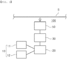
- FIG. 1 a schematic view of a deposition apparatus of the present disclosure is illustrated.
- a deposition apparatus in an embodiment of the present disclosure is a deposition apparatus 100 for coating two or more compounds or elements on a substrate S.
- the deposition apparatus 100 includes a supply unit 10 for supplying the two or more compounds or elements to a plurality of solid bodies; a heating unit 20 connected to the supply unit 10, and for melting and evaporating the solid bodies supplied from the supply unit to form vapor; a buffer unit 30, connected to the heating unit, in which the vapor remains and is mixed with previously generated vapor; and a nozzle 50 connected to the buffer unit and having an opening toward a substrate S.
- the supply unit 10 includes a first supply unit 11 for supplying a first solid body 13 (see FIG. 3 ) and a second supply unit 12 for supplying a second solid body 14 (see FIG. 3 ).
- first solid body and the second solid body use a solid body having a composition different from the target coating layer coated on the substrate.
- zinc and magnesium alloys are coated with a specific composition, zinc may be used as the first solid body, and magnesium may be used as the second body, and the composition of the zinc-magnesium alloy may be adjusted by controlling an amount of the supplied solid body.
- the solid body may include any one or more of zinc, magnesium, aluminum, lithium, indium, silver, and copper, and may be made of only one metal element.
- the composition ratio of the target coating layer may be matched to an entirety of a plurality of solid bodies, such that it is possible to match the composition ratio of the target coating layer by controlling an amount of the number supplied with the solid body facilitating manufacturing.
- the supply unit 10 provides the first and second solid bodies to the heating unit 20 simultaneously.
- 'simultaneously' means that the first and second solid bodies are supplied at the same timing, and the first and second solid bodies are successively supplied to supply the first and second solid bodies at substantially one timing.
- the heating unit 20 includes a crucible capable of receiving and melting/evaporating the supplied solid body and heating body providing heat to the solid body inside the crucible.
- a certain amount of molten metal is maintained in the crucible of the heating unit 20 to enable continuous coating, and heat is transferred to the solid body through the molten metal to melt the solid body.
- the heating body may be composed of an electromagnetic coil to allow electromagnetic stirring at the same time as heating, and the coil may be disposed anywhere inside or outside of the crucible.
- the vapor generated in the heating unit 20 passes through the buffer unit 30 and is then distributed to the substrate S, for example a strip, through the nozzle 50.
- the buffer unit 30 may be provided on a path through which the vapor generated from the heating unit, and be composed of a space unit for maintaining vapor, such that the vapor just generated in the heating unit 20 and the vapor previously generated may be mixed.
- the solid body is melted and evaporated, and the timing of melting and evaporation of the solid body may be different due to the composition, and thus vapor different from the composition ratio of the target coating layer may be temporarily generated.
- composition ratio of the entire solid body supplied by the present disclosure is the same as the composition ratio of the target coating layer, when all of the supplied solid bodies are evaporated, the composition ratio of the entire solid body supplied by the present disclosure may be the same as the target composition ratio.
- vapor in the buffer unit, vapor is not directly discharged through the nozzle but is mixed with the subsequent vapor while staying for a certain period of time, so the vapor discharged from the buffer unit may pass the nozzle 50 with a constant compositional ratio, unlike the generated vapor.
- the buffer unit 30 may maintain internal pressure of the buffer unit 30 to be higher than external pressure of the buffer unit 30, such that the vapor input into the buffer unit 30 may not be immediately discharged, but may be mixed with the subsequent vapor inside the buffer unit 30.
- heat may be provided to the vapor by providing a heat source outside of or inside the buffer unit 30 so that vapor does not condense inside the buffer unit 30.
- the buffer unit 30 is connected to a nozzle 50.
- the nozzle 50 sprays the vapor that has passed through the buffer unit 30 through an opening, and the vapor sprayed from the nozzle 50 is deposited on the substrate S to form a coating layer.
- the nozzle 50 may also be heated to prevent condensation of vapor passing through the same as the buffer unit 40.
- the heating unit 20, the buffer unit 30, and the nozzle 50 are disposed in a vacuum state inside a vacuum chamber.
- FIG. 2 another embodiment of the present disclosure is illustrated.
- the configuration of the heating unit 20, the buffer unit 30 and the nozzle 50 is the same as the embodiment of FIG. 1 , but it is configured such that the first supply unit 11 and the second supply unit 12 of the supply unit 10 does not separately supply a solid body to the heating unit 20, but the solid body of the first supply unit 11 and the solid body of the second supply unit 12 are supplied to the heating unit 20 through one path.
- any one of the solid bodies of the first supply unit and the second supply unit 11 and 12 is first supplied to the heating unit 20, and then the solid body of the other supply unit is successively supplied, and when the first supplied solid body is melted, a composition ratio of molten metal may fluctuate and a composition ratio of the generated vapor may not be identical to the composition ratio of the target coating layer.
- FIG. 3 a cross-sectional view of the embodiment of FIG. 2 is illustrated.
- the supply unit 10 is disposed outside of a vacuum chamber 1, and the supply unit 10 includes a first supply unit 11 for supplying a first solid body 13, a second supply unit 12 for supplying a second solid body 14, and a supply pipe 16 connected to the first supply pipe 11 and the second supply pipe 12, and extending into the non-conductive crucible 21 through the vacuum chamber 1.
- the supply pipe 16 is formed in a vertical direction so that the solid bodies 13 and 14 supplied to the supply pipe 16 can be moved to an end portion facing the heating unit by their own weights.
- An opening 19 is formed in the end portion 17 of the supply pipe 16, the end portion facing the heating unit. This will be described with reference to FIGS. 8 and 9 .
- FIG. 8 A cross-sectional view of an end portion 17 of a supply pipe 16, the end portion facing the heating unit, is illustrated in FIG. 8 , and in FIG. 9 , a case in which the supply pipe 16 is used and a case in which a general supply pipe is used is illustrated.
- openings 19a and 19b are formed on a lower surface and a side surface of the end portion 17 of the supply pipe 16, the end portion 17 facing the heating unit.
- the openings 19a and 19b are formed to be smaller than cross-sections of the first and second solid bodies 13 and 14 not to fall directly into the openings 19a and 19b when the solid bodies 13 and 14 introduced to the end portion 17.
- the plurality of openings 19a and 19b may be provided, and the openings 19a and 19b may be provided to have different sizes.
- molten metal 29 can be introduced and discharged through the openings 19a and 19b, the molten metal 29 is filled inside the end portion 17, and the solid bodies 13 and 14 are melted by the molten metal 29. Therefore, the solid bodies 13 and 14 are melted in a liquid state or a solid state of a small size in the molten metal 29, and it can be prevented that the temperature and volume of the molten metal 29 are rapidly changed in a mixing process.
- A shows that when a solid body was supplied according to the opening of FIG. 8
- B shows that when an end portion of a supply pipe 16 was opened and the solid body is directly was mixed into the molten metal 29.
- Zinc and magnesium was used as a solid body, and a zinc solid body and a magnesium solid body were supplied every 45 seconds.
- An induction heating unit 25 used the same induction heating unit.
- the heating unit 20 includes a crucible 21 disposed inside the vacuum chamber 1 and is a non-conductive container and an induction heating unit 25 disposed outside of the crucible 21 and is wound around the crucible 21.
- a certain amount of molten metal 29 in which the first and second solid bodies 13 and 14 are melted during an operation is maintained inside the crucible 21, and the end portion 17 of the heating unit of the supply pipe 16 extends into the molten metal 29, and is disposed such that at least an opening 19 is immersed in the molten metal.
- stirring of the molten metal 29 is required to overcome the difference in vapor pressures, and the induction heating unit 25 is provided to be induction-heated while stirring the molten metal 29 received in the crucible 21.
- a composition ration of an upper portion and an inner portion of an evaporation surface may be maintained to be the same by the electromagnetic stirring of the induction heating unit 25.
- the induction heating unit 25 may be located inside a vacuum, or may be located in air by installing a partition wall as an electrical non-conductor between the induction heating unit 25 and the crucible 21.
- an electromagnetic force generated by the electromagnetic coil has a property of heating stirring, and floating the metal located therein.
- an important function is heating and stirring of the molten metal 29 by the electromagnetic force, and the floating function is not important. Therefore, the induction heating unit 25 of the present disclosure may employ a non-floating electromagnetic coil, rather than a floating electromagnetic coil.
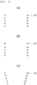
- the shape of the non-floating induction heating unit 25 is illustrated in FIG. 4 .
- various types such as a vertical type, a V type, and the like may be used, and the number of windings may vary, such as 2 or 5 turns, and a winding method may also use various forms such as a type of unidirectional winding, a type of bidirectional winding, and the like.
- the floating induction heating unit may be formed such that a diameter of a wire decreases toward a lower portion and a diameter of a bottom wire is formed very narrow, to impart a floating function.
- the floating-induction heating unit has disadvantages in that heating efficiency of the molten metal 29 is low due to lower concentration of the electromagnetic force for floating, and a flow of a coolant is not smooth due to the narrow diameter of the wire of the lower portion, so that a high current cannot be applied. Therefore, it is advantageous that the non-floating induction heating unit is applied from a viewpoint of a practical coating performance.
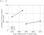
- FIG. 5 shows a result of comparing a dynamic coating speed coated with a substrate using a non-floating induction heating unit and a floating induction heating unit.
- a coating layer is a zinc-magnesium alloy.
- An upper diameter of the induction heating unit 25 is equal to 180mm, and the floating induction heating unit has a shape of A in FIG. 4 , and the non-floating induction heating unit has a shape in which a lower diameter thereof decreases.
- a coating speed is much higher in an example in which the non-floating induction heating unit is applied even though a current, much lower than a high frequency current applied to the floating induction heating unit is applied. Therefore, in an embodiment of the present disclosure, a non-floating induction heating unit was used to provide a high coating speed.
- the buffer unit 30 is located above the crucible 21.
- the buffer unit 30 is formed of a space unit having a predetermined area, but the internal pressure of the buffer unit 30 is higher than the external pressure of the buffer unit 30.
- the nozzle 50 is disposed to spray in a horizontal direction, and the buffer unit 30 disposed above the crucible 21 is formed as a space unit having an ' ⁇ ' shape.
- an upper surface area of the molten metal 29, which is an evaporation area, that is, an area of the opening 51 of the nozzle 50 is smaller than a cross-sectional area of the crucible 21 so that the internal pressure is higher than the external pressure in the buffer unit 30. Since the area of the opening 51 is smaller than the evaporation area, the generated vapor is not immediately discharged and remains in the buffer unit 30 for a constant time.
- FIG. 6 is a simulation view for simulating the vapor flow passing through the buffer unit 30 to move to the nozzle 50, and it can be seen that the vapor discharged from the heating unit 20 is rotated inside the buffer unit 30. Therefore, a constant composition ratio can be maintained by mixing the vapor generated first and the vapor generated later.
- the buffer unit 30 is connected to the nozzle 50.
- the nozzle 50 may have various types of openings 51, and may adopt an appropriate shape depending on the target substrate or conditions. As described above, the opening 51 must have a total area smaller than the evaporation area.
- FIG. 7 Various shapes of the nozzle are shown in FIG. 7 . As shown in FIG. 7 , slit-shaped openings 51 and 53 formed in a width direction or a height direction of the substrate (see A and C in FIG. 7 ), or a circular opening 52 disposed to be spaced apart by regular intervals (see B in FIG. 7 ) may also be illustrated.
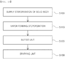
- the deposition method of the present disclosure includes a supply operation for supplying two or more solid bodies to one heating unit (S100); a vapor forming operation for melting and evaporating the solid body to form vapor (S110); a buffer operation in which the vapor and the previously formed vapor are mixed (S120); and a spraying unit for spraying the mixed vapor onto a substrate (S130).
- the solid bodies may include any one or more of zinc, magnesium, aluminum, lithium, indium, silver, and copper, and may be made of only one metal element. Therefore, it is possible to form a coating layer having another composition ratio with two solid bodies having different composition ratios.
- a solid body is supplied so that a composition ratio of the entire solid body to be supplied is identical to a composition ratio of a target coating layer.
- the solid body is supplied through a supply pipe extending into molten metal of a crucible in which the solid body is received and melted and evaporated.
- the vapor forming operation (S110) at least a portion of the solid body is formed is melted and is then discharged from the supply pipe and mixes with the molten metal.
- the buffer operation (S120) is a operation in which the vapor generated in the vapor forming operation (S110) is mixed with the previously generated vapor, and in which the internal pressure is higher than the external pressure, so that the vapor does not immediately be discharged through a nozzle and remains mixed in the apparatus. Due to the buffer operation (S120), it is possible to form a coating layer with vapor having a constant composition ratio by buffering deviations in the composition ratio generated during melting/evaporation of the solid body.
- the spraying operation (S130) is an operation in which mixed vapor is sprayed through the nozzle of the deposition apparatus, and in which the vapor is deposited on a substrate to form a coating layer on the substrate.
- a coating layer is formed at a constant composition ratio.
- Results of experiments with the apparatus of the embodiment of FIG. 3 are as follows.
- a target coating layer was an alloy coating of zinc and magnesium (weight ratio: 10.8 wt% Mg).
- a non-conductive container made of a ceramic material was used as a crucible 21 . Initially, 2 kg of a zinc-magnesium alloy was placed into the container, and induction heating was performed using an induction heating unit 25 to form molten metal. An inner diameter of the container was set to 140 mm, and a cross-sectional area of the opening 51 of the nozzle 50 through which the vapor is sprayed was set to be 7,000 mm 2 in total, so that it was configured such that the vapor is mixed in the buffer unit 30. In addition, a heater was used around the nozzle 50 and the buffer unit 30 to heat it to 800°C or higher.
- composition of the initial alloy that is introduced into the non-conductive container is not related to a coating composition.
- a composition of the supplied raw material is the same as the coating composition, other compositions may be coated at the beginning of the coating, but as time passes, coating of a desired composition can be stably performed at a uniform rate as soon.
Landscapes
- Chemical & Material Sciences (AREA)
- Engineering & Computer Science (AREA)
- Materials Engineering (AREA)
- Mechanical Engineering (AREA)
- Metallurgy (AREA)
- Organic Chemistry (AREA)
- Chemical Kinetics & Catalysis (AREA)
- Physical Vapour Deposition (AREA)
Abstract
Description
- The present disclosure relates to a deposition apparatus and a deposition method for coating two or more compounds or elements.
- Techniques for coating by vacuum deposition began to be widely used in the 1980s. Looking at the known technology, it can be largely divided into a simultaneous deposition method and a heat treatment method after the subsequent deposition process.
- A representative technique of the simultaneous deposition method is known from Japanese patent
JPH02-125866A2 EP1301649B1 , uniform mixing was attempted by maintaining choking conditions before or after mixing of metal vapors, but there are also practical limitations. - A technique for heat treatment after sequential deposition is disclosed in European patent
EP0756022B1 . After coating zinc using wet plating or a vacuum deposition method, magnesium is coated by the vacuum plating method and post-heat treatment to form a zinc-magnesium alloy coating layer. The above-described technique is a technique using diffusion, and has a disadvantage in that a composition of the coating layer in a depth direction is not uniform and an alloy between a base material and zinc by heat treatment is generated. In addition, the number of processes for alloy coating is increased, which is limited in terms of economic efficiency. - The present disclosure is to provide an apparatus and a method that is capable of performing continuous coating at a constant coating composition and rate.
- The present disclosure is to provide a deposition apparatus and a deposition method as follows.
- According to an aspect of the present disclosure, a deposition apparatus for coating two or more compounds or elements on a substrate is provided. The deposition apparatus includes: a supply unit for supplying the two or more compounds or elements to a plurality of solid bodies; a heating unit for melting and evaporating the solid bodies supplied from the supply unit to form vapor; a buffer unit, connected to the heating unit, in which the vapor remains and is mixed with previously generated vapor; and a nozzle connected to the buffer unit and having an opening toward the substrate.
- According to an aspect of the present disclosure, the supply unit supplies a solid body to the heating unit through a supply pipe, the supply pipe may include an end portion facing the heating unit, the end portion extending into molten metal of the heating unit, and an opening, smaller than a cross-section of the solid body may be formed in the end portion of the supply pipe facing the heating unit so that the supplied solid body is at least partially melted by the molten metal and is then discharged from the supply pipe.
- According to an embodiment of the present disclosure, the heating unit includes a crucible, and the buffer unit is a space connecting the nozzle and the crucible, wherein an area of the opening may be smaller than a cross-section of the crucible.
- According to an embodiment of the present disclosure, the supply unit may include a first supply unit for supplying a first solid body and a second supply unit for supplying a second solid body having a different element or compound from the first solid body. In this case, the first supply unit and the second supply unit may supply a solid body to the heating unit through a single supply pipe.
- According to an embodiment of the present disclosure, the first supply unit and the second supply unit may be disposed in a portion above the heating unit, so that the solid body in the supply pipe may be supplied to the heating unit by its own weight.
- According to an embodiment of the present disclosure, the heating unit may include a crucible and an electromagnetic coil disposed inside or outside of the crucible, and the electromagnetic coil may be a non-floating induction heating unit, and may be wound in a vertical direction.
- In an embodiment, each of the first solid body and the second solid body may include one or more of zinc, magnesium, aluminum, lithium, indium, silver, and copper.
- According to another embodiment of the present disclosure, a deposition method is provided. The deposition method includes: a supply operation for supplying two or more solid bodies to one heating unit simultaneously; a vapor forming operation for forming vapor by melting and evaporating the solid body; a buffer operation in which the vapor and the previously formed vapor are mixed; and a spraying operation for spraying the mixed vapor toward a coated material.
- According to an embodiment of the present disclosure, the solid body may include one or more of zinc, magnesium, aluminum, lithium, indium, silver, and copper, and the mixed vapor and the solid body may have different compositions from each other.
- According to an embodiment of the present disclosure, a composition ratio of the entire solid body supplied in the supply operation may be identical to a composition ratio of a target coating layer. In the supply operation, the solid body may be supplied through a supply pipe extending into molten metal of the crucible, and in the vapor forming operation, the solid body may be melted, and be then discharged from the supply pipe and mixed with the molten metal.
- According to an embodiment of the present disclosure, each of the solid bodies may include only one of zinc, magnesium, aluminum, lithium, indium, silver, and copper, and the composition ratio of the entire solid body supplied in the supply operation is identical to the composition ratio of the target coating layer.
- According to the present disclosure, continuous coating may be performed through the coating composition and speed through the configuration as described above.
-
-
FIG. 1 is a schematic view of an embodiment of the present disclosure. -
FIG. 2 is a schematic view of another embodiment of the present disclosure. -
FIG. 3 is a cross-sectional view of the present disclosure. -
FIG. 4 is a view illustrating a modification example of an electromagnetic coil of the embodiment ofFIG. 3 . -
FIG. 5 is a graph showing the coating speed when the type of the electromagnetic coil is changed in the embodiment ofFIG. 3 . -
FIG. 6 is a simulation view simulating a flow of vapor in a buffer unit of the embodiment ofFIG. 3 . -
FIG. 7 is a view illustrating a modification example of a nozzle of the embodiment ofFIG. 3 . -
FIG. 8 is a cross-sectional view of an end portion of a supply pipe of the embodiment ofFIG. 3 . -
FIG. 9 is a graph illustrating a coating speed to a shape of an end portion of a supply pipe. -
FIG. 10 is a schematic view of a deposition method of the present disclosure. - Hereinafter, specific embodiments of the present disclosure will be described with reference to the drawings.
- In
FIG. 1 , a schematic view of a deposition apparatus of the present disclosure is illustrated. - A deposition apparatus in an embodiment of the present disclosure is a
deposition apparatus 100 for coating two or more compounds or elements on a substrate S. Thedeposition apparatus 100 includes asupply unit 10 for supplying the two or more compounds or elements to a plurality of solid bodies; aheating unit 20 connected to thesupply unit 10, and for melting and evaporating the solid bodies supplied from the supply unit to form vapor; abuffer unit 30, connected to the heating unit, in which the vapor remains and is mixed with previously generated vapor; and anozzle 50 connected to the buffer unit and having an opening toward a substrate S. - In an embodiment of
FIG. 1 , thesupply unit 10 includes afirst supply unit 11 for supplying a first solid body 13 (seeFIG. 3 ) and asecond supply unit 12 for supplying a second solid body 14 (seeFIG. 3 ). In the present disclosure, two or more compounds or elements are coated on the substrate S, and the first solid body and the second solid body use a solid body having a composition different from the target coating layer coated on the substrate. For example, when zinc and magnesium alloys are coated with a specific composition, zinc may be used as the first solid body, and magnesium may be used as the second body, and the composition of the zinc-magnesium alloy may be adjusted by controlling an amount of the supplied solid body. - The solid body may include any one or more of zinc, magnesium, aluminum, lithium, indium, silver, and copper, and may be made of only one metal element. In an embodiment of the present disclosure, it is possible to form a coating layer having another composition with two solid bodies having different composition ratios. In particular, it may be difficult that a solid body having the same composition ratio as the coating layer is manufactured, but in the present disclosure, the composition ratio of the target coating layer may be matched to an entirety of a plurality of solid bodies, such that it is possible to match the composition ratio of the target coating layer by controlling an amount of the number supplied with the solid body facilitating manufacturing.
- Meanwhile, in this embodiment, the
supply unit 10 provides the first and second solid bodies to theheating unit 20 simultaneously. Here, 'simultaneously' means that the first and second solid bodies are supplied at the same timing, and the first and second solid bodies are successively supplied to supply the first and second solid bodies at substantially one timing. - The
heating unit 20 includes a crucible capable of receiving and melting/evaporating the supplied solid body and heating body providing heat to the solid body inside the crucible. In this embodiment, it is preferable that a certain amount of molten metal is maintained in the crucible of theheating unit 20 to enable continuous coating, and heat is transferred to the solid body through the molten metal to melt the solid body. The heating body may be composed of an electromagnetic coil to allow electromagnetic stirring at the same time as heating, and the coil may be disposed anywhere inside or outside of the crucible. - The vapor generated in the
heating unit 20 passes through thebuffer unit 30 and is then distributed to the substrate S, for example a strip, through thenozzle 50. Thebuffer unit 30 may be provided on a path through which the vapor generated from the heating unit, and be composed of a space unit for maintaining vapor, such that the vapor just generated in theheating unit 20 and the vapor previously generated may be mixed. In this embodiment, the solid body is melted and evaporated, and the timing of melting and evaporation of the solid body may be different due to the composition, and thus vapor different from the composition ratio of the target coating layer may be temporarily generated. - However, since the composition ratio of the entire solid body supplied by the present disclosure is the same as the composition ratio of the target coating layer, when all of the supplied solid bodies are evaporated, the composition ratio of the entire solid body supplied by the present disclosure may be the same as the target composition ratio.
- In an embodiment of the present disclosure, in the buffer unit, vapor is not directly discharged through the nozzle but is mixed with the subsequent vapor while staying for a certain period of time, so the vapor discharged from the buffer unit may pass the
nozzle 50 with a constant compositional ratio, unlike the generated vapor. - The
buffer unit 30 may maintain internal pressure of thebuffer unit 30 to be higher than external pressure of thebuffer unit 30, such that the vapor input into thebuffer unit 30 may not be immediately discharged, but may be mixed with the subsequent vapor inside thebuffer unit 30. In addition, heat may be provided to the vapor by providing a heat source outside of or inside thebuffer unit 30 so that vapor does not condense inside thebuffer unit 30. - The
buffer unit 30 is connected to anozzle 50. Thenozzle 50 sprays the vapor that has passed through thebuffer unit 30 through an opening, and the vapor sprayed from thenozzle 50 is deposited on the substrate S to form a coating layer. Thenozzle 50 may also be heated to prevent condensation of vapor passing through the same as the buffer unit 40. - The
heating unit 20, thebuffer unit 30, and thenozzle 50 are disposed in a vacuum state inside a vacuum chamber. - In
FIG. 2 , another embodiment of the present disclosure is illustrated. In an embodiment ofFIG. 2 , the configuration of theheating unit 20, thebuffer unit 30 and thenozzle 50 is the same as the embodiment ofFIG. 1 , but it is configured such that thefirst supply unit 11 and thesecond supply unit 12 of thesupply unit 10 does not separately supply a solid body to theheating unit 20, but the solid body of thefirst supply unit 11 and the solid body of thesecond supply unit 12 are supplied to theheating unit 20 through one path. - In this case, any one of the solid bodies of the first supply unit and the
second supply unit heating unit 20, and then the solid body of the other supply unit is successively supplied, and when the first supplied solid body is melted, a composition ratio of molten metal may fluctuate and a composition ratio of the generated vapor may not be identical to the composition ratio of the target coating layer. - In
FIG. 3 , a cross-sectional view of the embodiment ofFIG. 2 is illustrated. As shown inFIG. 3 , thesupply unit 10 is disposed outside of avacuum chamber 1, and thesupply unit 10 includes afirst supply unit 11 for supplying a firstsolid body 13, asecond supply unit 12 for supplying a secondsolid body 14, and asupply pipe 16 connected to thefirst supply pipe 11 and thesecond supply pipe 12, and extending into thenon-conductive crucible 21 through thevacuum chamber 1. Thesupply pipe 16 is formed in a vertical direction so that thesolid bodies supply pipe 16 can be moved to an end portion facing the heating unit by their own weights. Anopening 19 is formed in theend portion 17 of thesupply pipe 16, the end portion facing the heating unit. This will be described with reference toFIGS. 8 and9 . - A cross-sectional view of an
end portion 17 of asupply pipe 16, the end portion facing the heating unit, is illustrated inFIG. 8 , and inFIG. 9 , a case in which thesupply pipe 16 is used and a case in which a general supply pipe is used is illustrated. As shown inFIG. 8 ,openings end portion 17 of thesupply pipe 16, theend portion 17 facing the heating unit. In this case, theopenings solid bodies openings solid bodies end portion 17. The plurality ofopenings openings - Since molten
metal 29 can be introduced and discharged through theopenings molten metal 29 is filled inside theend portion 17, and thesolid bodies molten metal 29. Therefore, thesolid bodies molten metal 29, and it can be prevented that the temperature and volume of themolten metal 29 are rapidly changed in a mixing process. - In
FIG. 9 , A shows that when a solid body was supplied according to the opening ofFIG. 8 , and B shows that when an end portion of asupply pipe 16 was opened and the solid body is directly was mixed into themolten metal 29. Zinc and magnesium was used as a solid body, and a zinc solid body and a magnesium solid body were supplied every 45 seconds. Aninduction heating unit 25 used the same induction heating unit. - As shown in
FIG. 9 , it can be confirmed that a fluctuation width of a frequency was small in A, but in B, the frequency fluctuates significantly. In addition, it can be confirmed that in A, the frequency fluctuates within a certain range regardless of a supply cycle, but in B, the frequency fluctuates significantly every supply cycle. Since the frequency of the induction heating unit fluctuates depending on the volume of themolten metal 29, it can be seen that in A, a width of volume fluctuation of themolten metal 29 is not large, and thus, it can be seen that a surface area and a temperature of themolten metal 29 is low, to provide a constant amount of evaporation. - Returning to
FIG. 3 , theheating unit 20 includes acrucible 21 disposed inside thevacuum chamber 1 and is a non-conductive container and aninduction heating unit 25 disposed outside of thecrucible 21 and is wound around thecrucible 21. A certain amount ofmolten metal 29 in which the first and secondsolid bodies crucible 21, and theend portion 17 of the heating unit of thesupply pipe 16 extends into themolten metal 29, and is disposed such that at least anopening 19 is immersed in the molten metal. - In order to perform alloy/compound coating of a constant coating composition and speed, in particular, in order to achieve evaporation of two elements having different vapor pressures, stirring of the
molten metal 29 is required to overcome the difference in vapor pressures, and theinduction heating unit 25 is provided to be induction-heated while stirring themolten metal 29 received in thecrucible 21. A composition ration of an upper portion and an inner portion of an evaporation surface may be maintained to be the same by the electromagnetic stirring of theinduction heating unit 25. Theinduction heating unit 25 may be located inside a vacuum, or may be located in air by installing a partition wall as an electrical non-conductor between theinduction heating unit 25 and thecrucible 21. - In general, an electromagnetic force generated by the electromagnetic coil has a property of heating stirring, and floating the metal located therein. In the
induction heating unit 25 of this embodiment, an important function is heating and stirring of themolten metal 29 by the electromagnetic force, and the floating function is not important. Therefore, theinduction heating unit 25 of the present disclosure may employ a non-floating electromagnetic coil, rather than a floating electromagnetic coil. - The shape of the non-floating
induction heating unit 25 is illustrated inFIG. 4 . As shown inFIG. 4 , various types such as a vertical type, a V type, and the like may be used, and the number of windings may vary, such as 2 or 5 turns, and a winding method may also use various forms such as a type of unidirectional winding, a type of bidirectional winding, and the like. - Meanwhile, as presented in the Republic of Korea Patent
2009-0092627 molten metal 29 is low due to lower concentration of the electromagnetic force for floating, and a flow of a coolant is not smooth due to the narrow diameter of the wire of the lower portion, so that a high current cannot be applied. Therefore, it is advantageous that the non-floating induction heating unit is applied from a viewpoint of a practical coating performance. -
FIG. 5 shows a result of comparing a dynamic coating speed coated with a substrate using a non-floating induction heating unit and a floating induction heating unit. A coating layer is a zinc-magnesium alloy. An upper diameter of theinduction heating unit 25 is equal to 180mm, and the floating induction heating unit has a shape of A inFIG. 4 , and the non-floating induction heating unit has a shape in which a lower diameter thereof decreases. As shown inFIG. 5 , it can be confirmed that a coating speed is much higher in an example in which the non-floating induction heating unit is applied even though a current, much lower than a high frequency current applied to the floating induction heating unit is applied. Therefore, in an embodiment of the present disclosure, a non-floating induction heating unit was used to provide a high coating speed. - Returning to
FIG. 3 again, thebuffer unit 30 is located above thecrucible 21. Thebuffer unit 30 is formed of a space unit having a predetermined area, but the internal pressure of thebuffer unit 30 is higher than the external pressure of thebuffer unit 30. In the present embodiment, since the substrate S is standing in a vertical direction, thenozzle 50 is disposed to spray in a horizontal direction, and thebuffer unit 30 disposed above thecrucible 21 is formed as a space unit having an '¬' shape. - It is configured that an upper surface area of the
molten metal 29, which is an evaporation area, that is, an area of theopening 51 of thenozzle 50 is smaller than a cross-sectional area of thecrucible 21 so that the internal pressure is higher than the external pressure in thebuffer unit 30. Since the area of theopening 51 is smaller than the evaporation area, the generated vapor is not immediately discharged and remains in thebuffer unit 30 for a constant time. -
FIG. 6 is a simulation view for simulating the vapor flow passing through thebuffer unit 30 to move to thenozzle 50, and it can be seen that the vapor discharged from theheating unit 20 is rotated inside thebuffer unit 30. Therefore, a constant composition ratio can be maintained by mixing the vapor generated first and the vapor generated later. - Finally, the
buffer unit 30 is connected to thenozzle 50. Thenozzle 50 may have various types ofopenings 51, and may adopt an appropriate shape depending on the target substrate or conditions. As described above, theopening 51 must have a total area smaller than the evaporation area. - Various shapes of the nozzle are shown in
FIG. 7 . As shown inFIG. 7 , slit-shapedopenings FIG. 7 ), or acircular opening 52 disposed to be spaced apart by regular intervals (see B inFIG. 7 ) may also be illustrated. - A flow chart of another deposition method according to an embodiment of the present disclosure is illustrated in
FIG. 10 . The deposition method of the present disclosure includes a supply operation for supplying two or more solid bodies to one heating unit (S100); a vapor forming operation for melting and evaporating the solid body to form vapor (S110); a buffer operation in which the vapor and the previously formed vapor are mixed (S120); and a spraying unit for spraying the mixed vapor onto a substrate (S130). - In the supply operation (S100), the solid bodies may include any one or more of zinc, magnesium, aluminum, lithium, indium, silver, and copper, and may be made of only one metal element. Therefore, it is possible to form a coating layer having another composition ratio with two solid bodies having different composition ratios. In the supply operation (S100), a solid body is supplied so that a composition ratio of the entire solid body to be supplied is identical to a composition ratio of a target coating layer.
- In addition, in the supply operation (S100), the solid body is supplied through a supply pipe extending into molten metal of a crucible in which the solid body is received and melted and evaporated. In the vapor forming operation (S110), at least a portion of the solid body is formed is melted and is then discharged from the supply pipe and mixes with the molten metal.
- In the vapor forming operation (S110), it is advantageous that stirring and heating of the molten metal are performed simultaneously to be evaporated at a constant adjustment ratio. Therefore, it is preferable to dispose an induction heating unit outside of the crucible to simultaneously perform stirring and heating of the molten metal, but is not limited thereto, and a stirring unit and a heating unit may be configured separately.
- The buffer operation (S120) is a operation in which the vapor generated in the vapor forming operation (S110) is mixed with the previously generated vapor, and in which the internal pressure is higher than the external pressure, so that the vapor does not immediately be discharged through a nozzle and remains mixed in the apparatus. Due to the buffer operation (S120), it is possible to form a coating layer with vapor having a constant composition ratio by buffering deviations in the composition ratio generated during melting/evaporation of the solid body.
- The spraying operation (S130) is an operation in which mixed vapor is sprayed through the nozzle of the deposition apparatus, and in which the vapor is deposited on a substrate to form a coating layer on the substrate. In the spraying operation, since the vapor mixed in the buffer operation (S120) is supplied, a coating layer is formed at a constant composition ratio.
- Results of experiments with the apparatus of the embodiment of
FIG. 3 are as follows. As a solid body, two types of pure zinc and pure magnesium were used, and a target coating layer was an alloy coating of zinc and magnesium (weight ratio: 10.8 wt% Mg). - As a
crucible 21, a non-conductive container made of a ceramic material was used. Initially, 2 kg of a zinc-magnesium alloy was placed into the container, and induction heating was performed using aninduction heating unit 25 to form molten metal. An inner diameter of the container was set to 140 mm, and a cross-sectional area of theopening 51 of thenozzle 50 through which the vapor is sprayed was set to be 7,000 mm2 in total, so that it was configured such that the vapor is mixed in thebuffer unit 30. In addition, a heater was used around thenozzle 50 and thebuffer unit 30 to heat it to 800°C or higher. - To supplement the alloy molten metal consumed by evaporation, 61.2 g of two pure zinc solid bodies and 14.8 g of one pure magnesium solid body are supplied into the
molten metal 29 through thesupply unit 10. A total of three solid bodies (two pure zinc + one pure magnesium) were continuously introduced one by one, and an introduction time interval thereof was about 13.5 seconds. It is possible to continuously coat zinc and magnesium alloys on a substrate with a uniform composition and a uniform rate of 10 g/s by using such adeposition apparatus 100 and a deposition method. - The composition of the initial alloy that is introduced into the non-conductive container is not related to a coating composition. When if only a composition of the supplied raw material is the same as the coating composition, other compositions may be coated at the beginning of the coating, but as time passes, coating of a desired composition can be stably performed at a uniform rate as soon.
Claims (16)
- A deposition apparatus for coating two or more compounds or elements on a substrate, the substrate comprising:a supply unit for supplying the two or more compounds or elements to a plurality of solid bodies;a heating unit for melting and evaporating the solid bodies supplied from the supply unit to form vapor;a buffer unit, connected to the heating unit, in which the vapor remains and is mixed with previously generated vapor; anda nozzle connected to the buffer unit and having an opening toward a substrate.
- The deposition apparatus of claim 1, wherein the supply unit supplies a solid body to the heating unit, and
the supply pipe comprises an end portion facing the heating unit extending into molten metal of the heating unit. - The deposition apparatus of claim 2, wherein an opening, smaller than a cross-section of the solid body is formed in the end portion of the supply pipe, the end portion facing the heating unit, such that the supplied solid body is partially melted by the molten metal and is then discharged from the supply pipe.
- The deposition apparatus of any one of claims 1 to 3, wherein the heating unit comprises a crucible, and
the buffer unit is a space connecting the nozzle and the crucible, wherein an area of the opening is smaller than a cross-section of the crucible. - The deposition apparatus of claims 2 or 3, wherein the supply unit comprises a first supply unit for supplying a first solid body; and a second supply unit for supplying a second solid body having a different element or compound from the first solid body.
- The deposition apparatus of claim 5, wherein the first supply unit and the second supply unit supply a solid body to the heating unit through the one supply pipe.
- The deposition apparatus of claim 6, wherein the first supply unit and the second supply unit is located above the heating unit, and the solid body is supplied to the heating unit by its own weight in the supply pipe.
- The deposition apparatus of any one of claims 1 to 3, wherein the heating unit comprises a crucible and an electromagnetic coil disposed inside or outside of the crucible.
- The deposition apparatus of claim 8, wherein the electromagnetic coil is a non-floating induction heating unit.
- The deposition apparatus of claim 8, wherein the electromagnetic coil is wound in a vertical direction.
- The deposition apparatus of claim 5, wherein each of the first solid body and the second solid body comprises one or more of zinc, magnesium, aluminum, lithium, indium, silver, and copper.
- A deposition method, comprising:a supply operation for supplying two or more solid bodies to one heating unit simultaneously;a vapor forming operation for forming vapor by melting and evaporating the solid body;a buffer operation in which the vapor and the previously formed vapor are mixed; anda spraying operation for spraying the mixed vapor toward a substrate.
- The deposition method of claim 12, wherein the solid body comprises one or more of zinc, magnesium, aluminum, lithium, indium, silver and copper, and
the mixed vapor and the solid body have a different composition from each other. - The deposition method of claim 13, wherein a composition ratio of the entire solid body supplied in the supply operation is identical to a composition ratio of a target coating layer.
- The deposition method of claim 12, wherein in the supply operation, the solid body is supplied through a supply pipe extending into molten metal of a crucible in which the solid body is received and melted and evaporated, and
in the vapor forming operation, the solid body is at least partially melted and is then discharged from the supply pipe and mixed with the molten metal. - The deposition method of claim 12, wherein each of the solid body comprises only one of zinc, magnesium, aluminum, lithium, indium, silver, and copper, and
a composition ratio of the entire solid body supplied in the supply operation is identical to a composition ratio of the target coating layer.
Applications Claiming Priority (2)
| Application Number | Priority Date | Filing Date | Title |
|---|---|---|---|
| KR1020170179178A KR102098455B1 (en) | 2017-12-26 | 2017-12-26 | Continuous Vapor Deposition Device and Continuous Deposition Method |
| PCT/KR2018/012451 WO2019132206A1 (en) | 2017-12-26 | 2018-10-19 | Deposition apparatus and deposition method |
Publications (2)
| Publication Number | Publication Date |
|---|---|
| EP3733926A1 true EP3733926A1 (en) | 2020-11-04 |
| EP3733926A4 EP3733926A4 (en) | 2021-05-19 |
Family
ID=67064199
Family Applications (1)
| Application Number | Title | Priority Date | Filing Date |
|---|---|---|---|
| EP18895724.5A Pending EP3733926A4 (en) | 2017-12-26 | 2018-10-19 | Deposition apparatus and deposition method |
Country Status (6)
| Country | Link |
|---|---|
| US (1) | US20210017640A1 (en) |
| EP (1) | EP3733926A4 (en) |
| JP (1) | JP7128281B2 (en) |
| KR (1) | KR102098455B1 (en) |
| CN (1) | CN111542644B (en) |
| WO (1) | WO2019132206A1 (en) |
Families Citing this family (4)
| Publication number | Priority date | Publication date | Assignee | Title |
|---|---|---|---|---|
| WO2019239192A1 (en) * | 2018-06-15 | 2019-12-19 | Arcelormittal | Vacuum deposition facility and method for coating a substrate |
| GB2586635B (en) * | 2019-08-30 | 2024-01-24 | Dyson Technology Ltd | Deposition system |
| CN112575308B (en) | 2019-09-29 | 2023-03-24 | 宝山钢铁股份有限公司 | Vacuum coating device capable of efficiently coating strip steel under vacuum |
| CN117344289A (en) * | 2023-11-06 | 2024-01-05 | 甬江实验室 | Chemical vapor deposition apparatus |
Family Cites Families (19)
| Publication number | Priority date | Publication date | Assignee | Title |
|---|---|---|---|---|
| FR2611746B1 (en) * | 1987-03-06 | 1989-06-30 | Centre Nat Etd Spatiales | DEVICE FOR VACUUM EVAPORATION OF A CONTINUOUS METAL |
| JPH02125866A (en) * | 1988-11-04 | 1990-05-14 | Kobe Steel Ltd | Device for applying alloy plating by vapor deposition |
| JP2507804B2 (en) * | 1989-04-19 | 1996-06-19 | 東洋インキ製造株式会社 | Continuous vapor deposition method and apparatus |
| DE19527515C1 (en) | 1995-07-27 | 1996-11-28 | Fraunhofer Ges Forschung | Corrosion-resistant steel sheet prodn., e.g. for the automobile industry |
| JP4219476B2 (en) * | 1999-04-05 | 2009-02-04 | パナソニック株式会社 | Thin film forming method and thin film forming apparatus |
| EP1174526A1 (en) * | 2000-07-17 | 2002-01-23 | Nederlandse Organisatie voor Toegepast Natuurwetenschappelijk Onderzoek TNO | Continuous vapour deposition |
| NL1020059C2 (en) * | 2002-02-21 | 2003-08-25 | Corus Technology B V | Method and device for coating a substrate. |
| US7501151B2 (en) * | 2004-09-21 | 2009-03-10 | Eastman Kodak Company | Delivering particulate material to a vaporization zone |
| US20070231490A1 (en) * | 2006-03-29 | 2007-10-04 | Eastman Kodak Company | Uniformly vaporizing metals and organic materials |
| JP5063969B2 (en) * | 2006-09-29 | 2012-10-31 | 東京エレクトロン株式会社 | Vapor deposition apparatus, vapor deposition apparatus control apparatus, vapor deposition apparatus control method, and vapor deposition apparatus usage method |
| US20090020070A1 (en) * | 2007-07-19 | 2009-01-22 | Michael Schafer | Vacuum evaporation apparatus for solid materials |
| KR20090092627A (en) | 2008-02-27 | 2009-09-01 | 성균관대학교산학협력단 | Security device based on situation information and method thereof |
| EP2199425A1 (en) * | 2008-12-18 | 2010-06-23 | ArcelorMittal France | Industrial steam generator for depositing any alloy coating on a metal band (II) |
| CN102639746B (en) * | 2009-12-09 | 2014-03-12 | 株式会社爱发科 | Film forming device for organic thin films, and method for forming film using organic materials |
| KR101171535B1 (en) * | 2010-07-09 | 2012-08-07 | 아주대학교산학협력단 | Pre-treatment apparatus for improving a thin film and pre-treatmenting method |
| KR101207590B1 (en) * | 2010-12-27 | 2012-12-03 | 주식회사 포스코 | Metal Vapor Generating Apparatus |
| KR101461738B1 (en) * | 2012-12-21 | 2014-11-14 | 주식회사 포스코 | Apparatus for heating materials and coatting system having the same |
| US10131983B2 (en) * | 2013-11-05 | 2018-11-20 | Tata Steel Nederland Technology B.V. | Method and apparatus for controlling the composition of liquid metal in an evaporator device |
| US20160312356A1 (en) * | 2013-12-19 | 2016-10-27 | Posco | Heating apparatus and coating machine having same |
-
2017
- 2017-12-26 KR KR1020170179178A patent/KR102098455B1/en active Active
-
2018
- 2018-10-19 EP EP18895724.5A patent/EP3733926A4/en active Pending
- 2018-10-19 JP JP2020535209A patent/JP7128281B2/en active Active
- 2018-10-19 US US16/957,507 patent/US20210017640A1/en not_active Abandoned
- 2018-10-19 WO PCT/KR2018/012451 patent/WO2019132206A1/en not_active Ceased
- 2018-10-19 CN CN201880084151.6A patent/CN111542644B/en active Active
Also Published As
| Publication number | Publication date |
|---|---|
| KR20190077741A (en) | 2019-07-04 |
| JP7128281B2 (en) | 2022-08-30 |
| US20210017640A1 (en) | 2021-01-21 |
| EP3733926A4 (en) | 2021-05-19 |
| CN111542644A (en) | 2020-08-14 |
| WO2019132206A1 (en) | 2019-07-04 |
| KR102098455B1 (en) | 2020-04-07 |
| JP2021509146A (en) | 2021-03-18 |
| CN111542644B (en) | 2023-05-30 |
Similar Documents
| Publication | Publication Date | Title |
|---|---|---|
| EP3733926A1 (en) | Deposition apparatus and deposition method | |
| RU2456372C2 (en) | Procedure for application of coating on substrate and device for vacuum deposition of metal alloy | |
| US11781213B2 (en) | Apparatus and method for vacuum deposition | |
| JP6650442B2 (en) | Apparatus for forming a coating on the surface of a component, band-like material or tool | |
| KR20100126259A (en) | Industrial steam generator for depositing alloy coatings on metal strips | |
| KR101620639B1 (en) | Alloy Deposition Apparatus | |
| EP4029968B1 (en) | Vacuum coating device | |
| CN112538604B (en) | Device and method for supplementing liquid and stabilizing metal steam supply amount in vacuum coating | |
| US20190211440A1 (en) | Coating process using gas screen | |
| EP3092324B1 (en) | Coating process using gas screen | |
| EP3460091A1 (en) | Molten material supply unit and dry coating device comprising same | |
| EP4012067B1 (en) | Vacuum coating device | |
| JPH0297663A (en) | Production of steel sheet plated with zn-mg by vapor deposition | |
| EP4023788B1 (en) | Vacuum coating device | |
| JP2004063715A (en) | Semiconductor device manufacturing method and substrate processing apparatus | |
| CS198090B1 (en) | Device for vacuum forming coats on reflectors |
Legal Events
| Date | Code | Title | Description |
|---|---|---|---|
| STAA | Information on the status of an ep patent application or granted ep patent |
Free format text: STATUS: THE INTERNATIONAL PUBLICATION HAS BEEN MADE |
|
| PUAI | Public reference made under article 153(3) epc to a published international application that has entered the european phase |
Free format text: ORIGINAL CODE: 0009012 |
|
| STAA | Information on the status of an ep patent application or granted ep patent |
Free format text: STATUS: REQUEST FOR EXAMINATION WAS MADE |
|
| 17P | Request for examination filed |
Effective date: 20200716 |
|
| AK | Designated contracting states |
Kind code of ref document: A1 Designated state(s): AL AT BE BG CH CY CZ DE DK EE ES FI FR GB GR HR HU IE IS IT LI LT LU LV MC MK MT NL NO PL PT RO RS SE SI SK SM TR |
|
| AX | Request for extension of the european patent |
Extension state: BA ME |
|
| RIC1 | Information provided on ipc code assigned before grant |
Ipc: C23C 14/56 20060101ALI20210204BHEP Ipc: C23C 14/14 20060101ALI20210204BHEP Ipc: C23C 14/24 20060101AFI20210204BHEP Ipc: C22C 18/00 20060101ALI20210204BHEP Ipc: C23C 14/54 20060101ALI20210204BHEP Ipc: C23C 14/26 20060101ALI20210204BHEP |
|
| RIC1 | Information provided on ipc code assigned before grant |
Ipc: C23C 14/24 20060101AFI20210205BHEP Ipc: C23C 14/26 20060101ALI20210205BHEP Ipc: C23C 14/56 20060101ALI20210205BHEP Ipc: C22C 18/00 20060101ALI20210205BHEP Ipc: C23C 14/54 20060101ALI20210205BHEP Ipc: C23C 14/14 20060101ALI20210205BHEP |
|
| DAV | Request for validation of the european patent (deleted) | ||
| DAX | Request for extension of the european patent (deleted) | ||
| RIC1 | Information provided on ipc code assigned before grant |
Ipc: C23C 14/24 20060101AFI20210311BHEP Ipc: C23C 14/26 20060101ALI20210311BHEP Ipc: C23C 14/14 20060101ALI20210311BHEP Ipc: C23C 14/54 20060101ALI20210311BHEP Ipc: C23C 14/56 20060101ALI20210311BHEP Ipc: C22C 18/00 20060101ALI20210311BHEP |
|
| A4 | Supplementary search report drawn up and despatched |
Effective date: 20210421 |
|
| RIC1 | Information provided on ipc code assigned before grant |
Ipc: C23C 14/24 20060101AFI20210415BHEP Ipc: C23C 14/26 20060101ALI20210415BHEP Ipc: C23C 14/14 20060101ALI20210415BHEP Ipc: C23C 14/54 20060101ALI20210415BHEP Ipc: C23C 14/56 20060101ALI20210415BHEP Ipc: C22C 18/00 20060101ALI20210415BHEP |
|
| RAP3 | Party data changed (applicant data changed or rights of an application transferred) |
Owner name: POSCO HOLDINGS INC. |
|
| RAP1 | Party data changed (applicant data changed or rights of an application transferred) |
Owner name: POSCO CO., LTD |
|
| STAA | Information on the status of an ep patent application or granted ep patent |
Free format text: STATUS: EXAMINATION IS IN PROGRESS |
|
| 17Q | First examination report despatched |
Effective date: 20240506 |