EP3733538A1 - Synthetic resin container, preform, and method for producing synthetic resin container - Google Patents
Synthetic resin container, preform, and method for producing synthetic resin container Download PDFInfo
- Publication number
- EP3733538A1 EP3733538A1 EP18893503.5A EP18893503A EP3733538A1 EP 3733538 A1 EP3733538 A1 EP 3733538A1 EP 18893503 A EP18893503 A EP 18893503A EP 3733538 A1 EP3733538 A1 EP 3733538A1
- Authority
- EP
- European Patent Office
- Prior art keywords
- synthetic resin
- layer body
- mouth portion
- preform
- crystallized region
- Prior art date
- Legal status (The legal status is an assumption and is not a legal conclusion. Google has not performed a legal analysis and makes no representation as to the accuracy of the status listed.)
- Granted
Links
Images




Classifications
-
- B—PERFORMING OPERATIONS; TRANSPORTING
- B29—WORKING OF PLASTICS; WORKING OF SUBSTANCES IN A PLASTIC STATE IN GENERAL
- B29B—PREPARATION OR PRETREATMENT OF THE MATERIAL TO BE SHAPED; MAKING GRANULES OR PREFORMS; RECOVERY OF PLASTICS OR OTHER CONSTITUENTS OF WASTE MATERIAL CONTAINING PLASTICS
- B29B11/00—Making preforms
- B29B11/14—Making preforms characterised by structure or composition
-
- B—PERFORMING OPERATIONS; TRANSPORTING
- B29—WORKING OF PLASTICS; WORKING OF SUBSTANCES IN A PLASTIC STATE IN GENERAL
- B29C—SHAPING OR JOINING OF PLASTICS; SHAPING OF MATERIAL IN A PLASTIC STATE, NOT OTHERWISE PROVIDED FOR; AFTER-TREATMENT OF THE SHAPED PRODUCTS, e.g. REPAIRING
- B29C49/00—Blow-moulding, i.e. blowing a preform or parison to a desired shape within a mould; Apparatus therefor
- B29C49/071—Preforms or parisons characterised by their configuration, e.g. geometry, dimensions or physical properties
-
- B—PERFORMING OPERATIONS; TRANSPORTING
- B29—WORKING OF PLASTICS; WORKING OF SUBSTANCES IN A PLASTIC STATE IN GENERAL
- B29C—SHAPING OR JOINING OF PLASTICS; SHAPING OF MATERIAL IN A PLASTIC STATE, NOT OTHERWISE PROVIDED FOR; AFTER-TREATMENT OF THE SHAPED PRODUCTS, e.g. REPAIRING
- B29C49/00—Blow-moulding, i.e. blowing a preform or parison to a desired shape within a mould; Apparatus therefor
- B29C49/08—Biaxial stretching during blow-moulding
- B29C49/10—Biaxial stretching during blow-moulding using mechanical means for prestretching
- B29C49/12—Stretching rods
-
- B—PERFORMING OPERATIONS; TRANSPORTING
- B29—WORKING OF PLASTICS; WORKING OF SUBSTANCES IN A PLASTIC STATE IN GENERAL
- B29C—SHAPING OR JOINING OF PLASTICS; SHAPING OF MATERIAL IN A PLASTIC STATE, NOT OTHERWISE PROVIDED FOR; AFTER-TREATMENT OF THE SHAPED PRODUCTS, e.g. REPAIRING
- B29C49/00—Blow-moulding, i.e. blowing a preform or parison to a desired shape within a mould; Apparatus therefor
- B29C49/42—Component parts, details or accessories; Auxiliary operations
- B29C49/64—Heating or cooling preforms, parisons or blown articles
-
- B—PERFORMING OPERATIONS; TRANSPORTING
- B29—WORKING OF PLASTICS; WORKING OF SUBSTANCES IN A PLASTIC STATE IN GENERAL
- B29C—SHAPING OR JOINING OF PLASTICS; SHAPING OF MATERIAL IN A PLASTIC STATE, NOT OTHERWISE PROVIDED FOR; AFTER-TREATMENT OF THE SHAPED PRODUCTS, e.g. REPAIRING
- B29C49/00—Blow-moulding, i.e. blowing a preform or parison to a desired shape within a mould; Apparatus therefor
- B29C49/42—Component parts, details or accessories; Auxiliary operations
- B29C49/64—Heating or cooling preforms, parisons or blown articles
- B29C49/6409—Thermal conditioning of preforms
-
- B—PERFORMING OPERATIONS; TRANSPORTING
- B65—CONVEYING; PACKING; STORING; HANDLING THIN OR FILAMENTARY MATERIAL
- B65D—CONTAINERS FOR STORAGE OR TRANSPORT OF ARTICLES OR MATERIALS, e.g. BAGS, BARRELS, BOTTLES, BOXES, CANS, CARTONS, CRATES, DRUMS, JARS, TANKS, HOPPERS, FORWARDING CONTAINERS; ACCESSORIES, CLOSURES, OR FITTINGS THEREFOR; PACKAGING ELEMENTS; PACKAGES
- B65D1/00—Rigid or semi-rigid containers having bodies formed in one piece, e.g. by casting metallic material, by moulding plastics, by blowing vitreous material, by throwing ceramic material, by moulding pulped fibrous material or by deep-drawing operations performed on sheet material
- B65D1/02—Bottles or similar containers with necks or like restricted apertures, designed for pouring contents
- B65D1/0207—Bottles or similar containers with necks or like restricted apertures, designed for pouring contents characterised by material, e.g. composition, physical features
- B65D1/0215—Bottles or similar containers with necks or like restricted apertures, designed for pouring contents characterised by material, e.g. composition, physical features multilayered
-
- B—PERFORMING OPERATIONS; TRANSPORTING
- B65—CONVEYING; PACKING; STORING; HANDLING THIN OR FILAMENTARY MATERIAL
- B65D—CONTAINERS FOR STORAGE OR TRANSPORT OF ARTICLES OR MATERIALS, e.g. BAGS, BARRELS, BOTTLES, BOXES, CANS, CARTONS, CRATES, DRUMS, JARS, TANKS, HOPPERS, FORWARDING CONTAINERS; ACCESSORIES, CLOSURES, OR FITTINGS THEREFOR; PACKAGING ELEMENTS; PACKAGES
- B65D1/00—Rigid or semi-rigid containers having bodies formed in one piece, e.g. by casting metallic material, by moulding plastics, by blowing vitreous material, by throwing ceramic material, by moulding pulped fibrous material or by deep-drawing operations performed on sheet material
- B65D1/02—Bottles or similar containers with necks or like restricted apertures, designed for pouring contents
- B65D1/0223—Bottles or similar containers with necks or like restricted apertures, designed for pouring contents characterised by shape
- B65D1/023—Neck construction
-
- B—PERFORMING OPERATIONS; TRANSPORTING
- B65—CONVEYING; PACKING; STORING; HANDLING THIN OR FILAMENTARY MATERIAL
- B65D—CONTAINERS FOR STORAGE OR TRANSPORT OF ARTICLES OR MATERIALS, e.g. BAGS, BARRELS, BOTTLES, BOXES, CANS, CARTONS, CRATES, DRUMS, JARS, TANKS, HOPPERS, FORWARDING CONTAINERS; ACCESSORIES, CLOSURES, OR FITTINGS THEREFOR; PACKAGING ELEMENTS; PACKAGES
- B65D1/00—Rigid or semi-rigid containers having bodies formed in one piece, e.g. by casting metallic material, by moulding plastics, by blowing vitreous material, by throwing ceramic material, by moulding pulped fibrous material or by deep-drawing operations performed on sheet material
- B65D1/40—Details of walls
-
- B—PERFORMING OPERATIONS; TRANSPORTING
- B65—CONVEYING; PACKING; STORING; HANDLING THIN OR FILAMENTARY MATERIAL
- B65D—CONTAINERS FOR STORAGE OR TRANSPORT OF ARTICLES OR MATERIALS, e.g. BAGS, BARRELS, BOTTLES, BOXES, CANS, CARTONS, CRATES, DRUMS, JARS, TANKS, HOPPERS, FORWARDING CONTAINERS; ACCESSORIES, CLOSURES, OR FITTINGS THEREFOR; PACKAGING ELEMENTS; PACKAGES
- B65D23/00—Details of bottles or jars not otherwise provided for
- B65D23/02—Linings or internal coatings
-
- B—PERFORMING OPERATIONS; TRANSPORTING
- B65—CONVEYING; PACKING; STORING; HANDLING THIN OR FILAMENTARY MATERIAL
- B65D—CONTAINERS FOR STORAGE OR TRANSPORT OF ARTICLES OR MATERIALS, e.g. BAGS, BARRELS, BOTTLES, BOXES, CANS, CARTONS, CRATES, DRUMS, JARS, TANKS, HOPPERS, FORWARDING CONTAINERS; ACCESSORIES, CLOSURES, OR FITTINGS THEREFOR; PACKAGING ELEMENTS; PACKAGES
- B65D83/00—Containers or packages with special means for dispensing contents
- B65D83/771—Containers or packages with special means for dispensing contents for dispensing fluent contents by means of a flexible bag or a deformable membrane or diaphragm
-
- B—PERFORMING OPERATIONS; TRANSPORTING
- B29—WORKING OF PLASTICS; WORKING OF SUBSTANCES IN A PLASTIC STATE IN GENERAL
- B29C—SHAPING OR JOINING OF PLASTICS; SHAPING OF MATERIAL IN A PLASTIC STATE, NOT OTHERWISE PROVIDED FOR; AFTER-TREATMENT OF THE SHAPED PRODUCTS, e.g. REPAIRING
- B29C49/00—Blow-moulding, i.e. blowing a preform or parison to a desired shape within a mould; Apparatus therefor
- B29C49/02—Combined blow-moulding and manufacture of the preform or the parison
- B29C2049/024—Combined blow-moulding and manufacture of the preform or the parison not using inherent heat of the preform, i.e. 2 step blow moulding
-
- B—PERFORMING OPERATIONS; TRANSPORTING
- B29—WORKING OF PLASTICS; WORKING OF SUBSTANCES IN A PLASTIC STATE IN GENERAL
- B29C—SHAPING OR JOINING OF PLASTICS; SHAPING OF MATERIAL IN A PLASTIC STATE, NOT OTHERWISE PROVIDED FOR; AFTER-TREATMENT OF THE SHAPED PRODUCTS, e.g. REPAIRING
- B29C2949/00—Indexing scheme relating to blow-moulding
- B29C2949/07—Preforms or parisons characterised by their configuration
- B29C2949/0715—Preforms or parisons characterised by their configuration the preform having one end closed
-
- B—PERFORMING OPERATIONS; TRANSPORTING
- B29—WORKING OF PLASTICS; WORKING OF SUBSTANCES IN A PLASTIC STATE IN GENERAL
- B29C—SHAPING OR JOINING OF PLASTICS; SHAPING OF MATERIAL IN A PLASTIC STATE, NOT OTHERWISE PROVIDED FOR; AFTER-TREATMENT OF THE SHAPED PRODUCTS, e.g. REPAIRING
- B29C2949/00—Indexing scheme relating to blow-moulding
- B29C2949/07—Preforms or parisons characterised by their configuration
- B29C2949/074—Preforms or parisons characterised by their configuration having ribs or protrusions
-
- B—PERFORMING OPERATIONS; TRANSPORTING
- B29—WORKING OF PLASTICS; WORKING OF SUBSTANCES IN A PLASTIC STATE IN GENERAL
- B29C—SHAPING OR JOINING OF PLASTICS; SHAPING OF MATERIAL IN A PLASTIC STATE, NOT OTHERWISE PROVIDED FOR; AFTER-TREATMENT OF THE SHAPED PRODUCTS, e.g. REPAIRING
- B29C2949/00—Indexing scheme relating to blow-moulding
- B29C2949/07—Preforms or parisons characterised by their configuration
- B29C2949/074—Preforms or parisons characterised by their configuration having ribs or protrusions
- B29C2949/0744—Preforms or parisons characterised by their configuration having ribs or protrusions at neck portion
-
- B—PERFORMING OPERATIONS; TRANSPORTING
- B29—WORKING OF PLASTICS; WORKING OF SUBSTANCES IN A PLASTIC STATE IN GENERAL
- B29C—SHAPING OR JOINING OF PLASTICS; SHAPING OF MATERIAL IN A PLASTIC STATE, NOT OTHERWISE PROVIDED FOR; AFTER-TREATMENT OF THE SHAPED PRODUCTS, e.g. REPAIRING
- B29C2949/00—Indexing scheme relating to blow-moulding
- B29C2949/07—Preforms or parisons characterised by their configuration
- B29C2949/074—Preforms or parisons characterised by their configuration having ribs or protrusions
- B29C2949/0746—Preforms or parisons characterised by their configuration having ribs or protrusions at body portion
-
- B—PERFORMING OPERATIONS; TRANSPORTING
- B29—WORKING OF PLASTICS; WORKING OF SUBSTANCES IN A PLASTIC STATE IN GENERAL
- B29C—SHAPING OR JOINING OF PLASTICS; SHAPING OF MATERIAL IN A PLASTIC STATE, NOT OTHERWISE PROVIDED FOR; AFTER-TREATMENT OF THE SHAPED PRODUCTS, e.g. REPAIRING
- B29C2949/00—Indexing scheme relating to blow-moulding
- B29C2949/07—Preforms or parisons characterised by their configuration
- B29C2949/0861—Other specified values, e.g. values or ranges
- B29C2949/0862—Crystallinity
- B29C2949/0863—Crystallinity at the neck portion
-
- B—PERFORMING OPERATIONS; TRANSPORTING
- B29—WORKING OF PLASTICS; WORKING OF SUBSTANCES IN A PLASTIC STATE IN GENERAL
- B29C—SHAPING OR JOINING OF PLASTICS; SHAPING OF MATERIAL IN A PLASTIC STATE, NOT OTHERWISE PROVIDED FOR; AFTER-TREATMENT OF THE SHAPED PRODUCTS, e.g. REPAIRING
- B29C2949/00—Indexing scheme relating to blow-moulding
- B29C2949/30—Preforms or parisons made of several components
- B29C2949/3008—Preforms or parisons made of several components at neck portion
-
- B—PERFORMING OPERATIONS; TRANSPORTING
- B29—WORKING OF PLASTICS; WORKING OF SUBSTANCES IN A PLASTIC STATE IN GENERAL
- B29C—SHAPING OR JOINING OF PLASTICS; SHAPING OF MATERIAL IN A PLASTIC STATE, NOT OTHERWISE PROVIDED FOR; AFTER-TREATMENT OF THE SHAPED PRODUCTS, e.g. REPAIRING
- B29C2949/00—Indexing scheme relating to blow-moulding
- B29C2949/30—Preforms or parisons made of several components
- B29C2949/3012—Preforms or parisons made of several components at flange portion
-
- B—PERFORMING OPERATIONS; TRANSPORTING
- B29—WORKING OF PLASTICS; WORKING OF SUBSTANCES IN A PLASTIC STATE IN GENERAL
- B29C—SHAPING OR JOINING OF PLASTICS; SHAPING OF MATERIAL IN A PLASTIC STATE, NOT OTHERWISE PROVIDED FOR; AFTER-TREATMENT OF THE SHAPED PRODUCTS, e.g. REPAIRING
- B29C2949/00—Indexing scheme relating to blow-moulding
- B29C2949/30—Preforms or parisons made of several components
- B29C2949/3016—Preforms or parisons made of several components at body portion
-
- B—PERFORMING OPERATIONS; TRANSPORTING
- B29—WORKING OF PLASTICS; WORKING OF SUBSTANCES IN A PLASTIC STATE IN GENERAL
- B29C—SHAPING OR JOINING OF PLASTICS; SHAPING OF MATERIAL IN A PLASTIC STATE, NOT OTHERWISE PROVIDED FOR; AFTER-TREATMENT OF THE SHAPED PRODUCTS, e.g. REPAIRING
- B29C2949/00—Indexing scheme relating to blow-moulding
- B29C2949/30—Preforms or parisons made of several components
- B29C2949/302—Preforms or parisons made of several components at bottom portion
-
- B—PERFORMING OPERATIONS; TRANSPORTING
- B29—WORKING OF PLASTICS; WORKING OF SUBSTANCES IN A PLASTIC STATE IN GENERAL
- B29C—SHAPING OR JOINING OF PLASTICS; SHAPING OF MATERIAL IN A PLASTIC STATE, NOT OTHERWISE PROVIDED FOR; AFTER-TREATMENT OF THE SHAPED PRODUCTS, e.g. REPAIRING
- B29C2949/00—Indexing scheme relating to blow-moulding
- B29C2949/30—Preforms or parisons made of several components
- B29C2949/3032—Preforms or parisons made of several components having components being injected
-
- B—PERFORMING OPERATIONS; TRANSPORTING
- B29—WORKING OF PLASTICS; WORKING OF SUBSTANCES IN A PLASTIC STATE IN GENERAL
- B29C—SHAPING OR JOINING OF PLASTICS; SHAPING OF MATERIAL IN A PLASTIC STATE, NOT OTHERWISE PROVIDED FOR; AFTER-TREATMENT OF THE SHAPED PRODUCTS, e.g. REPAIRING
- B29C2949/00—Indexing scheme relating to blow-moulding
- B29C2949/30—Preforms or parisons made of several components
- B29C2949/3032—Preforms or parisons made of several components having components being injected
- B29C2949/3034—Preforms or parisons made of several components having components being injected having two or more components being injected
-
- B—PERFORMING OPERATIONS; TRANSPORTING
- B29—WORKING OF PLASTICS; WORKING OF SUBSTANCES IN A PLASTIC STATE IN GENERAL
- B29C—SHAPING OR JOINING OF PLASTICS; SHAPING OF MATERIAL IN A PLASTIC STATE, NOT OTHERWISE PROVIDED FOR; AFTER-TREATMENT OF THE SHAPED PRODUCTS, e.g. REPAIRING
- B29C2949/00—Indexing scheme relating to blow-moulding
- B29C2949/30—Preforms or parisons made of several components
- B29C2949/3086—Interaction between two or more components, e.g. type of or lack of bonding
- B29C2949/3094—Interaction between two or more components, e.g. type of or lack of bonding preform having at least partially loose components, e.g. at least partially loose layers
-
- B—PERFORMING OPERATIONS; TRANSPORTING
- B29—WORKING OF PLASTICS; WORKING OF SUBSTANCES IN A PLASTIC STATE IN GENERAL
- B29K—INDEXING SCHEME ASSOCIATED WITH SUBCLASSES B29B, B29C OR B29D, RELATING TO MOULDING MATERIALS OR TO MATERIALS FOR MOULDS, REINFORCEMENTS, FILLERS OR PREFORMED PARTS, e.g. INSERTS
- B29K2995/00—Properties of moulding materials, reinforcements, fillers, preformed parts or moulds
- B29K2995/0037—Other properties
- B29K2995/0041—Crystalline
- B29K2995/0043—Crystalline non-uniform
-
- B—PERFORMING OPERATIONS; TRANSPORTING
- B29—WORKING OF PLASTICS; WORKING OF SUBSTANCES IN A PLASTIC STATE IN GENERAL
- B29L—INDEXING SCHEME ASSOCIATED WITH SUBCLASS B29C, RELATING TO PARTICULAR ARTICLES
- B29L2009/00—Layered products
- B29L2009/001—Layered products the layers being loose
-
- B—PERFORMING OPERATIONS; TRANSPORTING
- B29—WORKING OF PLASTICS; WORKING OF SUBSTANCES IN A PLASTIC STATE IN GENERAL
- B29L—INDEXING SCHEME ASSOCIATED WITH SUBCLASS B29C, RELATING TO PARTICULAR ARTICLES
- B29L2031/00—Other particular articles
- B29L2031/712—Containers; Packaging elements or accessories, Packages
- B29L2031/7158—Bottles
-
- B—PERFORMING OPERATIONS; TRANSPORTING
- B65—CONVEYING; PACKING; STORING; HANDLING THIN OR FILAMENTARY MATERIAL
- B65D—CONTAINERS FOR STORAGE OR TRANSPORT OF ARTICLES OR MATERIALS, e.g. BAGS, BARRELS, BOTTLES, BOXES, CANS, CARTONS, CRATES, DRUMS, JARS, TANKS, HOPPERS, FORWARDING CONTAINERS; ACCESSORIES, CLOSURES, OR FITTINGS THEREFOR; PACKAGING ELEMENTS; PACKAGES
- B65D2205/00—Venting means
- B65D2205/02—Venting holes
-
- B—PERFORMING OPERATIONS; TRANSPORTING
- B65—CONVEYING; PACKING; STORING; HANDLING THIN OR FILAMENTARY MATERIAL
- B65D—CONTAINERS FOR STORAGE OR TRANSPORT OF ARTICLES OR MATERIALS, e.g. BAGS, BARRELS, BOTTLES, BOXES, CANS, CARTONS, CRATES, DRUMS, JARS, TANKS, HOPPERS, FORWARDING CONTAINERS; ACCESSORIES, CLOSURES, OR FITTINGS THEREFOR; PACKAGING ELEMENTS; PACKAGES
- B65D2501/00—Containers having bodies formed in one piece
- B65D2501/0009—Bottles or similar containers with necks or like restricted apertures designed for pouring contents
- B65D2501/0018—Ribs
Definitions
- the present disclosure relates to a synthetic resin-made container having an outer layer body and an inner layer body separably laminated on the inner surface of the outer layer body, a preform, and a method of manufacturing a synthetic resin-made container.
- Delamination containers are conventionally known as containers for containing food seasonings such as soy sauce, beverages, cosmetics such as skin lotions, and toiletries such as shampoos, hair conditioners, and liquid soaps as content liquids (for example, see PTL 1).
- Such a delamination container has a double structure in which an inner layer body having a space for containing a content liquid and capable of volume-reduction deformation is separably laminated on the inner surface of an outer layer body forming an outer shell of the container and including a tubular mouth portion, a barrel portion connected to the mouth portion, and a bottom portion closing the lower end of the barrel portion.
- the delamination container is used, for example, as a squeeze-type discharge container combined with a discharge cap having a check valve, or a pump-type container combined with a pump.
- the content liquid can be discharged to the outside by squeezing (compressing) the barrel portion of the outer layer body or operating the pump.
- the outer layer body After discharging the content liquid, by introducing outside air between the inner layer body and the outer layer body from an outside air introduction hole formed in the outer layer body, the outer layer body can be restored to the original shape while the inner layer body remains volume-reduction deformed.
- the content liquid contained in the inner layer body can be discharged without replacing it with outside air, so that contact of the content liquid contained in the inner layer body with outside air can be reduced and degradation or degeneration of the content liquid can be suppressed.
- the delamination container can be manufactured by stretch blow molding an outer body made of an olefin-based synthetic resin material such as polypropylene (PP) or polyethylene (PE) and an inner body located on the radially inner side of the outer body and made of a synthetic resin material having low compatibility with the synthetic resin material for the outer body, such as nylon or ethylene-vinyl alcohol copolymer resin (EVOH).
- PP polypropylene
- PE polyethylene
- EVOH ethylene-vinyl alcohol copolymer resin
- the unstretched part of the inner body near the outside air introduction hole may expand radially outward during blow molding and block the air passage from the outside air introduction hole to the space between the outer layer body and the inner layer body in the barrel portion. This leaves room for improvement.
- a synthetic resin-made container is a synthetic resin-made container that has an outer layer body and an inner layer body separably laminated on an inner surface of the outer layer body and is formed by stretch blow molding, the synthetic resin-made container comprising: a tubular mouth portion; a shoulder portion located below the mouth portion and increasing in diameter downward; a barrel portion connected to and located below the shoulder portion; and a bottom portion closing a lower end of the barrel portion, wherein the mouth portion has an outside air introduction hole for introducing outside air into a space between the outer layer body and the inner layer body, and the inner layer body is made of a crystalline resin, and has, in at least a part of the mouth portion in the inner layer body, a crystallized region having a higher degree of crystallinity than other regions.
- the crystallized region has lower visible light transmittance than the other regions.
- the crystallized region is a predetermined region below a neck ring formed in the mouth portion.
- the shoulder portion has a vertical rib extending in a vertical direction, the vertical rib being concave or convex.
- a groove depth of the vertical rib that is concave or a projection height of the vertical rib that is convex is smaller in at least one of an upper end and a lower end of the vertical rib than in a center of the vertical rib.
- the crystallized region extends to at least an upper end of the vertical rib.
- a preform according to the present disclosure is a preform that is made of a synthetic resin, has an outer body and an inner body laminated on an inner surface of the outer body, and is used in stretch blow molding, the preform comprising: a tubular mouth portion; a barrel portion located below the mouth portion; and a bottom portion closing a lower end of the barrel portion, wherein the mouth portion has an outside air introduction hole formed through the outer body, and the inner body is made of a crystalline resin, and has, in at least a part of the mouth portion in the inner body, a crystallized region having a higher degree of crystallinity than other regions.
- the crystallized region is an unstretched part in the stretch blow molding.
- an air passage rib extending in a vertical direction is formed on an outer circumferential surface in at least a part of the crystallized region.
- the air passage rib extends from the outside air introduction hole to the crystallized region.
- a method of manufacturing a synthetic resin-made container is a method of manufacturing a synthetic resin-made container by stretch blow molding a preform that has an outer body and an inner body laminated on an inner surface of the outer body, the preform including: a tubular mouth portion; a barrel portion located below the mouth portion; and a bottom portion closing a lower end of the barrel portion, wherein the mouth portion has an outside air introduction hole formed through the outer body, the method comprising: molding the outer body and the inner body that is made of a crystalline resin; reheating and cooling at least a part of the mouth portion in the inner body, to form a crystallized region having a higher degree of crystallinity than other regions; fitting the inner body having the crystallized region onto an inner circumferential surface of the outer body, to form a preform; and stretch blow molding the preform to form a synthetic resin-made container.
- the cooling of the at least a part of the mouth portion in the inner body is slow cooling without forced cooling.
- a synthetic resin-made container 1 according to one of the disclosed embodiments illustrated in FIGS. 1 and 2 is called a delamination container, and has a double structure including an outer layer body 2 and an inner layer body 3.
- the external shape of the synthetic resin-made container 1 is a bottle shape including a cylindrical mouth portion 4, a shoulder portion 7 located below the mouth portion 4 and increasing in diameter downward, a cylindrical barrel portion 5 connected to and located below the shoulder portion 7, and a bottom portion 6 closing the lower end of the barrel portion 5.
- vertical direction refers to an upward-downward direction in a state in which the synthetic resin-made container 1 is in an upright position as illustrated in FIG. 1 .
- radially outward refers to a direction toward the outside along a straight line that passes the central axis O1 of the synthetic resin-made container 1 and is perpendicular to the central axis O1 in FIG. 1 .
- radially inward refers to a direction toward the central axis O1 along the straight line.
- the mouth portion 4 has a male screw 4a.
- a discharge member such as a discharge cap or a discharge pump can be attached to the mouth portion 4 by screw connection to the male screw 4a.
- the mouth portion 4 may have an annular protrusion instead of the male screw 4a so that a discharge member such as a discharge cap can be attached to the mouth portion 4 by undercut engagement through capping.
- a lower part of the mouth portion 4 is provided with a neck ring 8 for fixing to a mold for blow molding when molding the synthetic resin-made container 1 by, for example, stretch blow molding.
- the outer layer body 2 forms an outer shell of the synthetic resin-made container 1, and may be made of a synthetic resin material such as polypropylene (PP), polyethylene (PE), or polyethylene terephthalate (PET).
- PP polypropylene
- PE polyethylene
- PET polyethylene terephthalate
- the part of the outer layer body 2 corresponding to the barrel portion 5 is flexible, and can dent when squeezed (compressed) and also return to the original shape from the dented state.
- the synthetic resin-made container 1 is used as a pump-type container, the part of the outer layer body 2 corresponding to the barrel portion 5 need not be squeezable.
- the inner layer body 3 may be made of a synthetic resin material, such as nylon or ethylene-vinyl alcohol copolymer resin (EVOH), that is a crystalline resin and has low compatibility with the synthetic resin material forming the outer layer body 2, in a bag shape thinner than the outer layer body 2.
- the inner layer body 3 is separably laminated on the inner surface of the outer layer body 2.
- the inside of the inner layer body 3 is a containing portion S connected to the opening of the mouth portion 4, and is capable of containing, for example, any of food seasonings such as soy sauce, beverages, cosmetics such as skin lotions, and toiletries such as shampoos, hair conditioners, and liquid soaps as contents.
- the crystalline resin included in the inner layer body 3 is a resin that is classified as thermoplastic resin and has crystalline parts in which molecular chains are regularly arranged. Crystalline parts and amorphous parts are mixed in the crystalline resin. The proportion of crystalline parts and amorphous parts depends on, for example, the cooling rate when cooling the crystalline resin after heating. Typically, in the case where a crystalline resin is slow-cooled after heating, the proportion of crystalline parts increases. A crystalline resin having a higher proportion of crystalline parts, i.e. a higher degree of crystallinity, has lower light transmittance because diffusion and reflection of light occur due to the refractive index difference between crystalline parts and amorphous parts.
- a crystalline resin having a high degree of crystallinity tends to have high rigidity.
- the degree of crystallinity can be measured, for example, by a density method, an X-ray diffraction method, a method by differential scanning calorimetry (DSC), a FT-IR method, or a solid state NMR method.
- the mouth portion 4 of the outer layer body 2 has an outside air introduction hole 4b for introducing outside air between the outer layer body 2 and the inner layer body 3, as illustrated in FIG. 1 .
- the outside air introduction hole 4b preferably has a function as a check valve or has a check valve attached thereto so as to introduce outside air between the outer layer body 2 and the inner layer body 3 but prevent air existing between the outer layer body 2 and the inner layer body 3 from flowing outside.
- the outside air introduction hole 4b may not be provided with a check valve or a check valve function.
- the shape of the outside air introduction hole 4b is not limited to a long hole shape illustrated in the drawing, and may be any of other various shapes such as a circular shape.
- the synthetic resin-made container 1 having such a structure can form a discharge container when a discharge member such as a discharge cap is attached to the mouth portion 4.
- a discharge member such as a discharge cap
- the contents can be discharged to the outside from the discharge member, and, with the discharge of the contents, the inner layer body 3 can separate from the inner surface of the outer layer body 2 and volume-reduction deform.
- outside air is introduced between the outer layer body 2 and the inner layer body 3 from the outside air introduction hole 4b formed in the outer layer body 2, as a result of which the outer layer body 2 can return to the original shape while the inner layer body 3 remains volume-reduction deformed.
- the contents contained in the containing portion S can be discharged without replacing the contents with outside air, so that contact of the contents contained in the containing portion S with outside air can be reduced and degradation and degeneration of the contents can be suppressed.
- the synthetic resin-made container 1 has a crystallized region 9 in a predetermined region below the neck ring 8 in the mouth portion 4, as illustrated in FIG. 1 .
- the crystallized region 9 is a region whose light transmittance has decreased as a result of increasing the degree of crystallinity to such an extent that whitens the inner layer body 3 in the region.
- the synthetic resin-made container 1 is formed by stretch blow molding, with a neck ring 18 of a preform 11 (see FIG. 3B , etc.) corresponding to the neck ring 8 in FIG. 1 being fixed to a mold for blow molding.
- the region which is an unstretched part below the neck ring 8 tends to expand radially outward due to high pressure air from the inside during the stretch blow molding.
- the air passage formed between the inner layer body 3 and the outer layer body 2 is blocked and the movement of air from the outside air introduction hole 4b to the space between the outer layer body 2 and the inner layer body 3 in the barrel portion 5 is obstructed.
- the degree of crystallinity is increased to such an extent that whitens the inner layer body 3, thus increasing the elastic modulus and securing high rigidity.
- whitening refers to a state in which the light transmittance decreases as a result of increasing the degree of crystallinity in the crystalline resin as mentioned above, and the color is not limited to white.
- the crystallized region 9 is formed in the predetermined region below the neck ring 8, as illustrated in FIG. 1 .
- the crystallized region 9 may include the neck ring 8, or extend to a position above the neck ring 8.
- the crystallized region 9 may extend to the height of the outside air introduction hole 4b.
- the crystallized region 9 may also extend to the shoulder portion 7 over the lower end of the mouth portion 4.
- the crystallized region 9 has a higher elastic modulus than the other regions, and resists stretching during the stretch blow molding. Thus, the air passage in the gap between the outer body 12 and the inner body 13 can be secured. If the crystallized region 9 is not provided, even the region near and below the neck ring 18 is stretched during the blow molding, as a result of which the air passage in the gap between the outer body 12 and the inner body 13 is blocked.
- the shoulder portion 7 in the synthetic resin-made container 1 has at least one vertical rib 10 extending in the vertical direction, as illustrated in FIG. 1 .
- a gap is formed between the inner layer body 3 and the outer layer body 2 in the surrounding region of the vertical rib 10 after initial separation treatment of separating the inner layer body 3 from the outer layer body 2 by a method such as blowing air in from the outside air introduction hole 4b and restoring the inner layer body 3 to the original shape by injecting air from the upper end opening of the mouth portion 4.
- outside air can be easily introduced between the inner layer body 3 and the outer layer body 2 from the outside air introduction hole 4b through the gap during use (i.e. when discharging the contents).
- the crystallized region 9 and the upper end 10T of the vertical rib 10 are formed continuously, as illustrated in FIG. 1 . Accordingly, outside air introduced from the outside air introduction hole 4b can easily reach the vertical rib 10, because the air passage between the outer layer body 2 and the inner layer body 3 in the crystallized region 9 is secured. The outside air that has reached the vertical rib 10 can easily reach the barrel portion 5 through the gap between the outer layer body 2 and the inner layer body 3 in the vertical rib 10, thus allowing smooth contraction of the inner layer body 3.
- the height of the lower end of the crystallized region 9 and the height of the upper end 10T of the vertical rib 10 approximately match, as illustrated in FIG. 1 .
- the present disclosure is not limited to such.
- the crystallized region 9 and the vertical rib 10 may overlap each other in the height direction.
- the vertical rib 10 and the crystallized region 9 may be away from each other in the height direction, or the vertical rib 10 may be omitted.
- 18 vertical ribs 10 are arranged at regular intervals in the circumferential direction, as illustrated in FIG. 2 .
- the number of vertical ribs 10, the length of each vertical rib 10, and the like may be varied.
- each vertical rib 10 is formed as a concave rib that extends in the vertical direction and is depressed toward the inside of the container.
- the shape of the inner layer body 3 is a concave rib shape corresponding to the shape of the outer layer body 2.
- the groove depth of the vertical rib 10 is smaller in the upper end 10T and the lower end 10B than in the central part 10M in the vertical direction. As a result of the groove depth being smaller in the upper end 10T and the lower end 10B, the inner layer body 3 can easily separate from the outer layer body 2 at the vertical rib 10 in the initial separation treatment.
- the groove depth of the vertical rib 10 is smaller in the upper end 10T and the lower end 10B, and the inner layer body 3 easily separates from the outer layer body 2 at the upper end 10T or the lower end 10B. Therefore, a process of separating the inner layer body 3 from the outer layer body 2 and a subsequent process of restoring the inner layer body 3 to the original shape can be performed smoothly, and the intended gap can be easily formed between the inner layer body 3 and the outer layer body 2 at the position of the vertical rib 10.
- the vertical rib 10 in this embodiment smoothly connects to the outer surface of the shoulder portion 7 at the upper end 10T and the lower end 10B.
- the inner layer body 3 can be separated more smoothly at the position of the upper end 10T or the lower end 10B of the vertical rib 10 in the initial separation treatment.
- the lower end 10B of the vertical rib 10 is located above the lower end of the shoulder portion 7.
- the vertical rib 10 extends from the shoulder portion 7 to the barrel portion 5 so that the lower end 10B is located in the barrel portion 5
- the inner layer body 3 is not easily separated at the lower end 10B in the initial separation treatment.
- the vertical rib 10 may extend from the shoulder portion 7 to the barrel portion 5 so that the lower end 10B is located in the barrel portion 5.
- each vertical rib 10 extends in the radial direction of the synthetic resin-made container 1 in a planar view of the synthetic resin-made container 1. Moreover, each vertical rib 10 extends approximately linearly from the upper end 10T to the lower end 10B. However, the present disclosure is not limited to such, and each vertical rib 10 may be bent or curved.
- each vertical rib 10 is smaller in the upper end 10T and the lower end 10B, i.e. each vertical rib 10 tapers down toward the upper end 10T and the lower end 10B.
- Each vertical rib 10 may be a convex rib projecting from the surface of the shoulder portion 7 toward the outside of the container.
- the projection height of the vertical rib 10 is preferably smaller at least in the upper end 10T or the lower end 10B than in the central part 10M.
- the cross-sectional shape of the vertical rib 10 is a convex shape in the inner layer body 3 corresponding to the convex shape in the outer layer body 2.
- the synthetic resin-made container 1 can be formed by stretch blow molding the synthetic resin-made preform 11 according to one of the disclosed embodiments illustrated in FIGS. 3A and 3B .
- the preform 11 has a double structure including a synthetic resin-made outer body 12 for forming the outer layer body 2 and a synthetic resin-made inner body 13 for forming the inner layer body 3.
- the external shape of the preform 11 is a bottomed tubular shape (approximately test tube shape) including a cylindrical mouth portion 14, a cylindrical barrel portion 15 connected to and located below the mouth portion 14, and a bottom portion 16 closing the lower end of the barrel portion 15.
- the mouth portion 14 is formed in a shape corresponding to the mouth portion 4 of the synthetic resin-made container 1, and has a male screw 14a and an outside air introduction hole 14b formed through the outer body 12.
- the bottom portion 16 is formed in a curved shape (semispherical shape).
- An open part at the upper end of the inner body 13 is provided with an annular flange 14c projecting radially outward.
- the open part of the inner body 13 is fixed to the open end.
- Reference sign O2 is a central axis common to the mouth portion 14, the barrel portion 15, and the bottom portion 16.
- the outer body 12 may be made of the same synthetic resin material as the outer layer body 2, i.e. a synthetic resin material that is stretch blow moldable, such as polyethylene terephthalate (PET), polypropylene (PP), or polyethylene (PE).
- the inner body 13 may be made of the same synthetic resin material as the inner layer body 3, i.e. a synthetic resin material such as polyethylene terephthalate (PET), nylon, or ethylene-vinyl alcohol copolymer resin (EVOH).
- PET polyethylene terephthalate
- PP polypropylene
- PE polyethylene
- the inner body 13 is thinner than the outer body 12, and is laminated on the inner surface of the outer body 12 so as to cover the whole inner surface.
- the inner body 13 may be a single layer structure formed by only a single synthetic resin, or may be a structure formed by a plurality of synthetic resins (e.g. PET/Ny/PET or PET+Ny blend) in order to improve barrier property or content resistance.
- synthetic resins e.g. PET/Ny/PET or PET+Ny blend
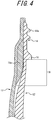
- a crystallized region 19 is formed below the neck ring 18 in the inner body 13, as illustrated in FIG. 4 .
- the crystallized region 19 is a region whose degree of crystallinity has been increased, for example, by slow cooling the crystalline resin after heating, as mentioned above.
- the crystallized region 19 has its degree of crystallinity increased to such an extent that whitens the inner body 13.
- the rigidity of the inner body 13 in the region can be enhanced to prevent the inner body 13 from expanding radially outward during the stretch blow molding and thus secure the air passage for outside air.
- Air passage ribs 19a are formed in the crystallized region 19 of the inner body 13, as illustrated in FIG. 5B .
- the air passage ribs 19a project radially outward from the outer circumferential surface in the mouth portion 14.
- Three air passage ribs 19a on the left and three air passage ribs 19a on the right in FIG. 5A are arranged symmetrically with respect to the outside air introduction hole 14b.
- Each air passage rib 19a extends in the vertical direction from above the outside air introduction hole 14b in the mouth portion 14 of the preform 11 to the lower end of the crystallized region 19, as illustrated in FIGS. 3A, 3B , and 4 .
- the air passage ribs 19a By forming the air passage ribs 19a at such a height position that includes at least a part of the crystallized region 19 in this way, not only an air passage can be secured by improvement in the rigidity of the inner body 13 in the crystallized region 19 but also a wider air passage can be secured through the space between the air passage ribs 19a. Consequently, in the synthetic resin-made container 1 obtained by stretch blow molding the preform 11, outside air introduced from the outside air introduction hole 4b can be smoothly supplied to the barrel portion 5.
- the air passage ribs 19a extend upward to the height of the outside air introduction hole 14b, so that outside air introduced from the outside air introduction hole 14b can be more smoothly supplied to the barrel portion 5 through the air passage ribs 19a.
- the air passage ribs 19a extend from the outside air introduction hole 14b to the crystallized region 19.
- the present disclosure is not limited to such, as long as the air passage ribs 19a are formed at least at such a height position that includes a part of the crystallized region 19.
- three air passage ribs 19a on the left and three air passage ribs 19a on the right are arranged symmetrically with respect to the outside air introduction hole 14b.
- the present disclosure is not limited to such, as long as at least one air passage rib 19a is provided.
- the number of air passage ribs 19a and the spacing between the air passage ribs 19a can be freely determined.
- FIG. 6 is a flowchart illustrating a procedure of performing the method of manufacturing the synthetic resin-made container 1 according to this embodiment.
- the outer body 12 illustrated in FIGS. 3A and 3B is molded by injection molding (step S101).
- the inner body 13 illustrated in FIGS. 3A, 3B , 5A, and 5B is molded by another injection molding process (step S102).
- the molding order is not limited, as the outer body 12 and the inner body 13 can be molded independently of each other.
- the molding of the outer body 12 and the inner body 13 is not limited to injection molding, and other molding methods such as compression molding may be used.
- the crystallized region 19 is formed in the inner body 13 molded in step S102 (step S103).
- the crystallized region 19 can be formed by, after the injection molding of the inner body 13 is completed and the inner body 13 is rapidly cooled, reheating only a predetermined region below the neck ring 18 and then slow-cooling the predetermined region without performing forced cooling such as air cooling using a fan. To reheat only the predetermined region below the neck ring 18, for example, the regions other than the predetermined region are masked.
- the crystallized region 19 may be formed by, when molding the inner body 13 by injection molding, slow-cooling only the predetermined region in a process of cooling the resin from the molten state.
- crystallization treatment is performed to increase the degree of crystallinity to such an extent that whitens the crystallized region 19.
- the present disclosure is not limited to such.
- the crystallized region 19 may be formed by performing crystallization treatment so that the crystallized region 19 has predetermined rigidity (modulus of longitudinal elasticity).
- step S104 the outer circumferential surface of the inner body 13 in which the crystallized region 19 has been formed in step S103 is fitted onto the inner circumferential surface of the outer body 12, to form the preform 11 (step S104).
- the inner body 13 is positioned relative to the outer body 12 in the vertical direction, as a result of the annular flange 14c which projects radially outward from the upper end of the mouth portion 14 of the inner body 13 abutting the open end of the outer body 12 from above, as illustrated in FIGS. 3A and 3B .
- the inner body 13 and the outer body 12 may be positioned relative to each other in the circumferential direction by fitting a protrusion formed on the outer circumferential surface of the inner body 13 into a depression formed on the inner circumferential surface of the outer body 12.
- the preform 11 formed in step S104 is stretch blow molded to produce the synthetic resin-made container 1 which is a delamination container (step S105).
- the stretch blow molding first, the preform 11 is heated in a heating furnace. Following this, from the heating state of the preform 11, the neck ring 18 of the preform 11 is caused to abut a reference plane of a mold for blow molding to be fixed to the mold, and the preform 11 is stretch blow molded. Consequently, the outer body 12 and the inner body 13 are blow molded radially outward by high pressure air, while being stretched downward by a stretching rod.
- the inner body 13 tends to expand radially outward due to the pressure of high pressure air blown into the preform 11.
- the crystallized region 19 having a high degree of crystallinity and a high elastic modulus is provided in the region below the neck ring 18 which is the unstretched part of the mouth portion 14, so that the region can be prevented from expanding radially outward due to high pressure air.
- an air passage for outside air from the outside air introduction hole 14b to the barrel portion 15 can be easily secured.
- the present disclosure is not limited to such.
- the mouth portion 4 and the barrel portion 5 may have a rectangular tubular shape or an elliptic tubular shape.
- the mouth portion 14 and the barrel portion 15 in the preform 11 have an approximately cylindrical shape in this embodiment, the present disclosure is not limited to such, and the mouth portion 14 and the barrel portion 15 may have, for example, a rectangular tubular shape or an elliptic tubular shape.
- the inner layer body 3 is made of a crystalline resin, and has, in at least a part of the mouth portion 4 in the inner layer body 3, the crystallized region 9 having a higher degree of crystallinity than the other regions.
- the inner body 13 can be prevented from expanding radially outward due to high pressure air and narrowing the air passage in part of the mouth portion 14.
- the air passage from the outside air introduction hole 4b to the space between the outer layer body 2 and the inner layer body 3 in the barrel portion 5 can therefore be easily secured.
- the visible light transmittance in the crystallized region 9 is lower than that in the other regions.
- the state in which the degree of crystallinity in the crystallized region 9 has increased to enhance the elastic modulus can be determined and managed based on the appearance.
- the crystallized region 9 is formed in the predetermined region below the neck ring 8 formed in the mouth portion 4.
- the region below the neck ring 8 which tends to expand radially outward in the stretch blow molding of the preform 11 can be enhanced in rigidity to resist deformation.
- the air passage from the outside air introduction hole 4b to the space between the outer layer body 2 and the inner layer body 3 in the barrel portion 5 can therefore be easily secured.
- the shoulder portion 7 has the concave or convex vertical rib 10 extending in the vertical direction. This allows outside air introduced from the outside air introduction hole 4b to reach the barrel portion 5 through the gap between the outer layer body 2 and the inner layer body 3 at the vertical rib 10.
- the groove depth of the vertical rib 10 is smaller in the upper end 10T and the lower end 10B than in the central part 10M.
- the inner layer body 3 can easily separate from the outer layer body 2 at the vertical rib 10 in the initial separation treatment of the inner layer body 3.
- the crystallized region 9 extends to the upper end 10T of the vertical rib 10. This allows outside air introduced from the outside air introduction hole 4b through the air passage secured in the crystallized region 9 to easily reach the barrel portion 5 through the gap between the outer layer body 2 and the inner layer body 3 at the vertical rib 10.
- the inner body 13 is made of a crystalline resin, and has, in at least a part of the mouth portion 14 in the inner body 13, the crystallized region 19 having a higher degree of crystallinity than the other regions.
- the inner body 13 can be prevented from expanding radially outward due to high pressure air and narrowing the air passage in part of the mouth portion 14.
- the air passage from the outside air introduction hole 4b to the space between the outer layer body 2 and the inner layer body 3 in the barrel portion 5 can therefore be easily secured.
- the crystallized region 19 is an unstretched part in the stretch blow molding.
- the inner body 13 can be prevented from expanding radially outward due to high pressure air and narrowing the air passage in the unstretched part of the mouth portion 14.
- the air passage from the outside air introduction hole 4b to the space between the outer layer body 2 and the inner layer body 3 in the barrel portion 5 can therefore be easily secured.
- the air passage rib 19a extending in the vertical direction is formed on the outer circumferential surface in the crystallized region 19.
- an air passage can be secured by improvement in the rigidity of the inner body 13 in the crystallized region 19 but also a wider air passage can be secured through the space between the air passage ribs 19a. Consequently, in the synthetic resin-made container 1 obtained by stretch blow molding the preform 11, outside air introduced from the outside air introduction hole 4b can be more smoothly supplied to the barrel portion 5.
- the air passage rib 19a extends from the outside air introduction hole 14b to the crystallized region 19.
- outside air introduced from the outside air introduction hole 4b can be seamlessly supplied to the barrel portion 5 through the air passage secured by the crystallized region 9 and the air passage secured by the air passage rib 19a.
- the method of manufacturing the synthetic resin-made container 1 includes heating and cooling at least a part of the mouth portion 14 in the inner body 13 to form the crystallized region 19 having a higher degree of crystallinity than the other regions.
- the cooling of the at least a part of the mouth portion 14 in the inner body 13 is slow cooling without forced cooling.
- the inner body 13 can be prevented from expanding radially outward due to high pressure air and narrowing the air passage in part of the mouth portion 14.
- the air passage from the outside air introduction hole 4b to the space between the outer layer body 2 and the inner layer body 3 in the barrel portion 5 can therefore be easily secured.
- the preform 11 was produced using IPA (isophthalic acid)-modified PET (IV value: 0.8) as the material of the outer body 12 and the inner body 13.
- the density in the whitened part (crystallized region 19) of the mouth portion 14 was 1.37 [g/cm 3 ], and the density in the parts other than the whitened part was 1.33 [g/cm 3 ].
- IPA isophthalic acid
- the density in the parts other than the whitened part was 1.33 [g/cm 3 ].
- a density of 1.35 [g/cm 3 ] or more was secured in the crystallization of the mouth portion 14, outside air was able to be introduced from the outside air introduction hole 4b in the synthetic resin-made container 1 after stretch blow molding.
- PET resins other than IPA-modified PET such as CHDM-modified PET or homo-PET, may be used.
Landscapes
- Engineering & Computer Science (AREA)
- Mechanical Engineering (AREA)
- Manufacturing & Machinery (AREA)
- Ceramic Engineering (AREA)
- Physics & Mathematics (AREA)
- Thermal Sciences (AREA)
- Geometry (AREA)
- Containers Having Bodies Formed In One Piece (AREA)
- Blow-Moulding Or Thermoforming Of Plastics Or The Like (AREA)
Abstract
Description
- This application claims priority to and the benefit of Japanese Patent Application No.
2017-254564 filed on December 28, 2017 - The present disclosure relates to a synthetic resin-made container having an outer layer body and an inner layer body separably laminated on the inner surface of the outer layer body, a preform, and a method of manufacturing a synthetic resin-made container.
- Delamination containers are conventionally known as containers for containing food seasonings such as soy sauce, beverages, cosmetics such as skin lotions, and toiletries such as shampoos, hair conditioners, and liquid soaps as content liquids (for example, see PTL 1).
- Such a delamination container has a double structure in which an inner layer body having a space for containing a content liquid and capable of volume-reduction deformation is separably laminated on the inner surface of an outer layer body forming an outer shell of the container and including a tubular mouth portion, a barrel portion connected to the mouth portion, and a bottom portion closing the lower end of the barrel portion. The delamination container is used, for example, as a squeeze-type discharge container combined with a discharge cap having a check valve, or a pump-type container combined with a pump. In this case, the content liquid can be discharged to the outside by squeezing (compressing) the barrel portion of the outer layer body or operating the pump. After discharging the content liquid, by introducing outside air between the inner layer body and the outer layer body from an outside air introduction hole formed in the outer layer body, the outer layer body can be restored to the original shape while the inner layer body remains volume-reduction deformed. With such a delamination container, the content liquid contained in the inner layer body can be discharged without replacing it with outside air, so that contact of the content liquid contained in the inner layer body with outside air can be reduced and degradation or degeneration of the content liquid can be suppressed.
- For example, the delamination container can be manufactured by stretch blow molding an outer body made of an olefin-based synthetic resin material such as polypropylene (PP) or polyethylene (PE) and an inner body located on the radially inner side of the outer body and made of a synthetic resin material having low compatibility with the synthetic resin material for the outer body, such as nylon or ethylene-vinyl alcohol copolymer resin (EVOH).
- PTL 1:
JP 2012-116516 A - In the case where the delamination container manufactured by stretch blow molding the double preform has the outside air introduction hole in the mouth portion, the unstretched part of the inner body near the outside air introduction hole may expand radially outward during blow molding and block the air passage from the outside air introduction hole to the space between the outer layer body and the inner layer body in the barrel portion. This leaves room for improvement.
- It could therefore be helpful to provide a synthetic resin-made container, a preform, and a method of manufacturing a synthetic resin-made container that can easily secure an air passage from an outside air introduction hole to a barrel portion.
- A synthetic resin-made container according to the present disclosure is a synthetic resin-made container that has an outer layer body and an inner layer body separably laminated on an inner surface of the outer layer body and is formed by stretch blow molding, the synthetic resin-made container comprising: a tubular mouth portion; a shoulder portion located below the mouth portion and increasing in diameter downward; a barrel portion connected to and located below the shoulder portion; and a bottom portion closing a lower end of the barrel portion, wherein the mouth portion has an outside air introduction hole for introducing outside air into a space between the outer layer body and the inner layer body, and the inner layer body is made of a crystalline resin, and has, in at least a part of the mouth portion in the inner layer body, a crystallized region having a higher degree of crystallinity than other regions.
- Preferably, in the synthetic resin-made container according to the present disclosure, the crystallized region has lower visible light transmittance than the other regions.
- Preferably, in the synthetic resin-made container according to the present disclosure, the crystallized region is a predetermined region below a neck ring formed in the mouth portion.
- Preferably, in the synthetic resin-made container according to the present disclosure, the shoulder portion has a vertical rib extending in a vertical direction, the vertical rib being concave or convex.
- Preferably, in the synthetic resin-made container according to the present disclosure, a groove depth of the vertical rib that is concave or a projection height of the vertical rib that is convex is smaller in at least one of an upper end and a lower end of the vertical rib than in a center of the vertical rib.
- Preferably, in the synthetic resin-made container according to the present disclosure, the crystallized region extends to at least an upper end of the vertical rib.
- A preform according to the present disclosure is a preform that is made of a synthetic resin, has an outer body and an inner body laminated on an inner surface of the outer body, and is used in stretch blow molding, the preform comprising: a tubular mouth portion; a barrel portion located below the mouth portion; and a bottom portion closing a lower end of the barrel portion, wherein the mouth portion has an outside air introduction hole formed through the outer body, and the inner body is made of a crystalline resin, and has, in at least a part of the mouth portion in the inner body, a crystallized region having a higher degree of crystallinity than other regions.
- Preferably, in the preform according to the present disclosure, the crystallized region is an unstretched part in the stretch blow molding.
- Preferably, in the preform according to the present disclosure, an air passage rib extending in a vertical direction is formed on an outer circumferential surface in at least a part of the crystallized region.
- Preferably, in the preform according to the present disclosure, the air passage rib extends from the outside air introduction hole to the crystallized region.
- A method of manufacturing a synthetic resin-made container according to the present disclosure is a method of manufacturing a synthetic resin-made container by stretch blow molding a preform that has an outer body and an inner body laminated on an inner surface of the outer body, the preform including: a tubular mouth portion; a barrel portion located below the mouth portion; and a bottom portion closing a lower end of the barrel portion, wherein the mouth portion has an outside air introduction hole formed through the outer body, the method comprising: molding the outer body and the inner body that is made of a crystalline resin; reheating and cooling at least a part of the mouth portion in the inner body, to form a crystallized region having a higher degree of crystallinity than other regions; fitting the inner body having the crystallized region onto an inner circumferential surface of the outer body, to form a preform; and stretch blow molding the preform to form a synthetic resin-made container.
- In the method of manufacturing a synthetic resin-made container according to the present disclosure, the cooling of the at least a part of the mouth portion in the inner body is slow cooling without forced cooling.
- It is thus possible to provide a synthetic resin-made container, a preform, and a method of manufacturing a synthetic resin-made container that can easily secure an air passage from an outside air introduction hole to a barrel portion.
- In the accompanying drawings:
-
FIG. 1 is a partial front sectional view of a synthetic resin-made container according to one of the disclosed embodiments; -
FIG. 2 is a plan view of the synthetic resin-made container according to one of the disclosed embodiments; -
FIG. 3A is a plan view of a preform according to one of the disclosed embodiments; -
FIG. 3B is a partial front sectional view of the preform according to one of the disclosed embodiments; -
FIG. 4 is an enlarged sectional view of a mouth portion inFIG. 3B ; -
FIG. 5A is a partial front sectional view of an inner body included in the preform according to one of the disclosed embodiments; -
FIG. 5B is a sectional view along section A-A inFIG. 5A ; and -
FIG. 6 is a flowchart illustrating a procedure of a method of manufacturing a synthetic resin-made container according to one of the disclosed embodiments. - More detailed description will be given below with reference to the drawings.
- A synthetic resin-made container 1 according to one of the disclosed embodiments illustrated in
FIGS. 1 and2 is called a delamination container, and has a double structure including anouter layer body 2 and an inner layer body 3. The external shape of the synthetic resin-made container 1 is a bottle shape including acylindrical mouth portion 4, ashoulder portion 7 located below themouth portion 4 and increasing in diameter downward, acylindrical barrel portion 5 connected to and located below theshoulder portion 7, and a bottom portion 6 closing the lower end of thebarrel portion 5. - In the description, the claims, and the drawings, the term "vertical direction" (upward-downward) refers to an upward-downward direction in a state in which the synthetic resin-made container 1 is in an upright position as illustrated in
FIG. 1 . The term "radially outward" refers to a direction toward the outside along a straight line that passes the central axis O1 of the synthetic resin-made container 1 and is perpendicular to the central axis O1 inFIG. 1 . The term "radially inward" refers to a direction toward the central axis O1 along the straight line. - The
mouth portion 4 has amale screw 4a. A discharge member such as a discharge cap or a discharge pump can be attached to themouth portion 4 by screw connection to themale screw 4a. Themouth portion 4 may have an annular protrusion instead of themale screw 4a so that a discharge member such as a discharge cap can be attached to themouth portion 4 by undercut engagement through capping. A lower part of themouth portion 4 is provided with aneck ring 8 for fixing to a mold for blow molding when molding the synthetic resin-made container 1 by, for example, stretch blow molding. - An example in which the synthetic resin-made container 1 is used as a squeeze-type discharge container will be described below.
- The
outer layer body 2 forms an outer shell of the synthetic resin-made container 1, and may be made of a synthetic resin material such as polypropylene (PP), polyethylene (PE), or polyethylene terephthalate (PET). The part of theouter layer body 2 corresponding to thebarrel portion 5 is flexible, and can dent when squeezed (compressed) and also return to the original shape from the dented state. In the case where the synthetic resin-made container 1 is used as a pump-type container, the part of theouter layer body 2 corresponding to thebarrel portion 5 need not be squeezable. - The inner layer body 3 may be made of a synthetic resin material, such as nylon or ethylene-vinyl alcohol copolymer resin (EVOH), that is a crystalline resin and has low compatibility with the synthetic resin material forming the
outer layer body 2, in a bag shape thinner than theouter layer body 2. The inner layer body 3 is separably laminated on the inner surface of theouter layer body 2. The inside of the inner layer body 3 is a containing portion S connected to the opening of themouth portion 4, and is capable of containing, for example, any of food seasonings such as soy sauce, beverages, cosmetics such as skin lotions, and toiletries such as shampoos, hair conditioners, and liquid soaps as contents. - The crystalline resin included in the inner layer body 3 is a resin that is classified as thermoplastic resin and has crystalline parts in which molecular chains are regularly arranged. Crystalline parts and amorphous parts are mixed in the crystalline resin. The proportion of crystalline parts and amorphous parts depends on, for example, the cooling rate when cooling the crystalline resin after heating. Typically, in the case where a crystalline resin is slow-cooled after heating, the proportion of crystalline parts increases. A crystalline resin having a higher proportion of crystalline parts, i.e. a higher degree of crystallinity, has lower light transmittance because diffusion and reflection of light occur due to the refractive index difference between crystalline parts and amorphous parts. A crystalline resin having a high degree of crystallinity tends to have high rigidity. The degree of crystallinity can be measured, for example, by a density method, an X-ray diffraction method, a method by differential scanning calorimetry (DSC), a FT-IR method, or a solid state NMR method.
- The
mouth portion 4 of theouter layer body 2 has an outsideair introduction hole 4b for introducing outside air between theouter layer body 2 and the inner layer body 3, as illustrated inFIG. 1 . The outsideair introduction hole 4b preferably has a function as a check valve or has a check valve attached thereto so as to introduce outside air between theouter layer body 2 and the inner layer body 3 but prevent air existing between theouter layer body 2 and the inner layer body 3 from flowing outside. The outsideair introduction hole 4b may not be provided with a check valve or a check valve function. The shape of the outsideair introduction hole 4b is not limited to a long hole shape illustrated in the drawing, and may be any of other various shapes such as a circular shape. - The synthetic resin-made container 1 having such a structure can form a discharge container when a discharge member such as a discharge cap is attached to the
mouth portion 4. In this case, by squeezing (compressing) the part of theouter layer body 2 corresponding to thebarrel portion 5, the contents can be discharged to the outside from the discharge member, and, with the discharge of the contents, the inner layer body 3 can separate from the inner surface of theouter layer body 2 and volume-reduction deform. After the squeeze is released, outside air is introduced between theouter layer body 2 and the inner layer body 3 from the outsideair introduction hole 4b formed in theouter layer body 2, as a result of which theouter layer body 2 can return to the original shape while the inner layer body 3 remains volume-reduction deformed. In this way, the contents contained in the containing portion S can be discharged without replacing the contents with outside air, so that contact of the contents contained in the containing portion S with outside air can be reduced and degradation and degeneration of the contents can be suppressed. - The synthetic resin-made container 1 according to the present disclosure has a crystallized
region 9 in a predetermined region below theneck ring 8 in themouth portion 4, as illustrated inFIG. 1 . The crystallizedregion 9 is a region whose light transmittance has decreased as a result of increasing the degree of crystallinity to such an extent that whitens the inner layer body 3 in the region. The synthetic resin-made container 1 is formed by stretch blow molding, with aneck ring 18 of a preform 11 (seeFIG. 3B , etc.) corresponding to theneck ring 8 inFIG. 1 being fixed to a mold for blow molding. Here, the region which is an unstretched part below theneck ring 8 tends to expand radially outward due to high pressure air from the inside during the stretch blow molding. In such a case, there is a possibility that the air passage formed between the inner layer body 3 and theouter layer body 2 is blocked and the movement of air from the outsideair introduction hole 4b to the space between theouter layer body 2 and the inner layer body 3 in thebarrel portion 5 is obstructed. In this embodiment, in the crystallizedregion 9 illustrated inFIG. 1 , the degree of crystallinity is increased to such an extent that whitens the inner layer body 3, thus increasing the elastic modulus and securing high rigidity. Consequently, the deformation of the inner layer body 3 in the crystallizedregion 9 during the stretch blow molding can be suppressed, with it being possible to prevent the obstruction of the movement of air from the outsideair introduction hole 4b to thebarrel portion 5. Herein, "whitening" refers to a state in which the light transmittance decreases as a result of increasing the degree of crystallinity in the crystalline resin as mentioned above, and the color is not limited to white. - In this embodiment, the crystallized
region 9 is formed in the predetermined region below theneck ring 8, as illustrated inFIG. 1 . However, the present disclosure is not limited to such. The crystallizedregion 9 may include theneck ring 8, or extend to a position above theneck ring 8. For example, the crystallizedregion 9 may extend to the height of the outsideair introduction hole 4b. The crystallizedregion 9 may also extend to theshoulder portion 7 over the lower end of themouth portion 4. - In this embodiment, the crystallized
region 9 has a higher elastic modulus than the other regions, and resists stretching during the stretch blow molding. Thus, the air passage in the gap between theouter body 12 and theinner body 13 can be secured. If the crystallizedregion 9 is not provided, even the region near and below theneck ring 18 is stretched during the blow molding, as a result of which the air passage in the gap between theouter body 12 and theinner body 13 is blocked. - The
shoulder portion 7 in the synthetic resin-made container 1 has at least onevertical rib 10 extending in the vertical direction, as illustrated inFIG. 1 . As a result of theshoulder portion 7 having thevertical rib 10, a gap is formed between the inner layer body 3 and theouter layer body 2 in the surrounding region of thevertical rib 10 after initial separation treatment of separating the inner layer body 3 from theouter layer body 2 by a method such as blowing air in from the outsideair introduction hole 4b and restoring the inner layer body 3 to the original shape by injecting air from the upper end opening of themouth portion 4. By forming such a gap between the inner layer body 3 and theouter layer body 2 in the surrounding region of thevertical rib 10, outside air can be easily introduced between the inner layer body 3 and theouter layer body 2 from the outsideair introduction hole 4b through the gap during use (i.e. when discharging the contents). - In particular, in this embodiment, the crystallized
region 9 and theupper end 10T of thevertical rib 10 are formed continuously, as illustrated inFIG. 1 . Accordingly, outside air introduced from the outsideair introduction hole 4b can easily reach thevertical rib 10, because the air passage between theouter layer body 2 and the inner layer body 3 in the crystallizedregion 9 is secured. The outside air that has reached thevertical rib 10 can easily reach thebarrel portion 5 through the gap between theouter layer body 2 and the inner layer body 3 in thevertical rib 10, thus allowing smooth contraction of the inner layer body 3. - In this embodiment, the height of the lower end of the crystallized
region 9 and the height of theupper end 10T of thevertical rib 10 approximately match, as illustrated inFIG. 1 . However, the present disclosure is not limited to such. The crystallizedregion 9 and thevertical rib 10 may overlap each other in the height direction. Thevertical rib 10 and the crystallizedregion 9 may be away from each other in the height direction, or thevertical rib 10 may be omitted. - In this embodiment, 18
vertical ribs 10 are arranged at regular intervals in the circumferential direction, as illustrated inFIG. 2 . The number ofvertical ribs 10, the length of eachvertical rib 10, and the like may be varied. - In this embodiment, each
vertical rib 10 is formed as a concave rib that extends in the vertical direction and is depressed toward the inside of the container. In the part where thevertical rib 10 is formed, the shape of the inner layer body 3 is a concave rib shape corresponding to the shape of theouter layer body 2. - The groove depth of the
vertical rib 10 is smaller in theupper end 10T and thelower end 10B than in thecentral part 10M in the vertical direction. As a result of the groove depth being smaller in theupper end 10T and thelower end 10B, the inner layer body 3 can easily separate from theouter layer body 2 at thevertical rib 10 in the initial separation treatment. - In the synthetic resin-made container 1 according to this embodiment, the groove depth of the
vertical rib 10 is smaller in theupper end 10T and thelower end 10B, and the inner layer body 3 easily separates from theouter layer body 2 at theupper end 10T or thelower end 10B. Therefore, a process of separating the inner layer body 3 from theouter layer body 2 and a subsequent process of restoring the inner layer body 3 to the original shape can be performed smoothly, and the intended gap can be easily formed between the inner layer body 3 and theouter layer body 2 at the position of thevertical rib 10. - The
vertical rib 10 in this embodiment smoothly connects to the outer surface of theshoulder portion 7 at theupper end 10T and thelower end 10B. With such a structure, the inner layer body 3 can be separated more smoothly at the position of theupper end 10T or thelower end 10B of thevertical rib 10 in the initial separation treatment. - In this embodiment, the
lower end 10B of thevertical rib 10 is located above the lower end of theshoulder portion 7. For example, in the case where thevertical rib 10 extends from theshoulder portion 7 to thebarrel portion 5 so that thelower end 10B is located in thebarrel portion 5, there is a possibility that the inner layer body 3 is not easily separated at thelower end 10B in the initial separation treatment. By locating thelower end 10B of thevertical rib 10 in theshoulder portion 7 as in this embodiment, on the other hand, the inner layer body 3 can be easily separated. Thevertical rib 10 may extend from theshoulder portion 7 to thebarrel portion 5 so that thelower end 10B is located in thebarrel portion 5. - As illustrated in
FIG. 2 , eachvertical rib 10 extends in the radial direction of the synthetic resin-made container 1 in a planar view of the synthetic resin-made container 1. Moreover, eachvertical rib 10 extends approximately linearly from theupper end 10T to thelower end 10B. However, the present disclosure is not limited to such, and eachvertical rib 10 may be bent or curved. - As illustrated in
FIGS. 1 and2 , the width (the groove width of the part open to the outer surface of theshoulder portion 7 in a direction perpendicular to the extending direction) of eachvertical rib 10 is smaller in theupper end 10T and thelower end 10B, i.e. eachvertical rib 10 tapers down toward theupper end 10T and thelower end 10B. With such a structure, the separability of the inner layer body 3 at thevertical rib 10 can be further enhanced. - Each
vertical rib 10 may be a convex rib projecting from the surface of theshoulder portion 7 toward the outside of the container. In such a case, the projection height of thevertical rib 10 is preferably smaller at least in theupper end 10T or thelower end 10B than in thecentral part 10M. In this case, the cross-sectional shape of thevertical rib 10 is a convex shape in the inner layer body 3 corresponding to the convex shape in theouter layer body 2. - The synthetic resin-made container 1 can be formed by stretch blow molding the synthetic resin-made
preform 11 according to one of the disclosed embodiments illustrated inFIGS. 3A and 3B . - The
preform 11 has a double structure including a synthetic resin-madeouter body 12 for forming theouter layer body 2 and a synthetic resin-madeinner body 13 for forming the inner layer body 3. The external shape of thepreform 11 is a bottomed tubular shape (approximately test tube shape) including acylindrical mouth portion 14, acylindrical barrel portion 15 connected to and located below themouth portion 14, and abottom portion 16 closing the lower end of thebarrel portion 15. Themouth portion 14 is formed in a shape corresponding to themouth portion 4 of the synthetic resin-made container 1, and has amale screw 14a and an outsideair introduction hole 14b formed through theouter body 12. Thebottom portion 16 is formed in a curved shape (semispherical shape). An open part at the upper end of theinner body 13 is provided with anannular flange 14c projecting radially outward. As a result of theflange 14c being laid over (placed on) the open end of theouter body 12, the open part of theinner body 13 is fixed to the open end. Reference sign O2 is a central axis common to themouth portion 14, thebarrel portion 15, and thebottom portion 16. - The
outer body 12 may be made of the same synthetic resin material as theouter layer body 2, i.e. a synthetic resin material that is stretch blow moldable, such as polyethylene terephthalate (PET), polypropylene (PP), or polyethylene (PE). Theinner body 13 may be made of the same synthetic resin material as the inner layer body 3, i.e. a synthetic resin material such as polyethylene terephthalate (PET), nylon, or ethylene-vinyl alcohol copolymer resin (EVOH). Theinner body 13 is thinner than theouter body 12, and is laminated on the inner surface of theouter body 12 so as to cover the whole inner surface. Theinner body 13 may be a single layer structure formed by only a single synthetic resin, or may be a structure formed by a plurality of synthetic resins (e.g. PET/Ny/PET or PET+Ny blend) in order to improve barrier property or content resistance. - A crystallized
region 19 is formed below theneck ring 18 in theinner body 13, as illustrated inFIG. 4 . The crystallizedregion 19 is a region whose degree of crystallinity has been increased, for example, by slow cooling the crystalline resin after heating, as mentioned above. In this embodiment, the crystallizedregion 19 has its degree of crystallinity increased to such an extent that whitens theinner body 13. Thus, the rigidity of theinner body 13 in the region can be enhanced to prevent theinner body 13 from expanding radially outward during the stretch blow molding and thus secure the air passage for outside air. -
Air passage ribs 19a are formed in the crystallizedregion 19 of theinner body 13, as illustrated inFIG. 5B . In this embodiment, theair passage ribs 19a project radially outward from the outer circumferential surface in themouth portion 14. Threeair passage ribs 19a on the left and threeair passage ribs 19a on the right inFIG. 5A are arranged symmetrically with respect to the outsideair introduction hole 14b. Eachair passage rib 19a extends in the vertical direction from above the outsideair introduction hole 14b in themouth portion 14 of thepreform 11 to the lower end of the crystallizedregion 19, as illustrated inFIGS. 3A, 3B , and4 . By forming theair passage ribs 19a at such a height position that includes at least a part of the crystallizedregion 19 in this way, not only an air passage can be secured by improvement in the rigidity of theinner body 13 in the crystallizedregion 19 but also a wider air passage can be secured through the space between theair passage ribs 19a. Consequently, in the synthetic resin-made container 1 obtained by stretch blow molding thepreform 11, outside air introduced from the outsideair introduction hole 4b can be smoothly supplied to thebarrel portion 5. In this embodiment, theair passage ribs 19a extend upward to the height of the outsideair introduction hole 14b, so that outside air introduced from the outsideair introduction hole 14b can be more smoothly supplied to thebarrel portion 5 through theair passage ribs 19a. - In this embodiment, the
air passage ribs 19a extend from the outsideair introduction hole 14b to the crystallizedregion 19. However, the present disclosure is not limited to such, as long as theair passage ribs 19a are formed at least at such a height position that includes a part of the crystallizedregion 19. - In this embodiment, three
air passage ribs 19a on the left and threeair passage ribs 19a on the right are arranged symmetrically with respect to the outsideair introduction hole 14b. However, the present disclosure is not limited to such, as long as at least oneair passage rib 19a is provided. The number ofair passage ribs 19a and the spacing between theair passage ribs 19a can be freely determined. - A method of manufacturing the synthetic resin-made container 1 according to one of the disclosed embodiments will be described below.
-
FIG. 6 is a flowchart illustrating a procedure of performing the method of manufacturing the synthetic resin-made container 1 according to this embodiment. - A method of forming the
preform 11 for manufacturing the synthetic resin-made container 1 by stretch blow molding will be described first. First, theouter body 12 illustrated inFIGS. 3A and 3B is molded by injection molding (step S101). Along with the molding of theouter body 12, theinner body 13 illustrated inFIGS. 3A, 3B ,5A, and 5B is molded by another injection molding process (step S102). Although the molding of theouter body 12 is followed by the molding of theinner body 13 inFIG. 6 , the molding order is not limited, as theouter body 12 and theinner body 13 can be molded independently of each other. The molding of theouter body 12 and theinner body 13 is not limited to injection molding, and other molding methods such as compression molding may be used. - Next, the crystallized
region 19 is formed in theinner body 13 molded in step S102 (step S103). For example, the crystallizedregion 19 can be formed by, after the injection molding of theinner body 13 is completed and theinner body 13 is rapidly cooled, reheating only a predetermined region below theneck ring 18 and then slow-cooling the predetermined region without performing forced cooling such as air cooling using a fan. To reheat only the predetermined region below theneck ring 18, for example, the regions other than the predetermined region are masked. Alternatively, the crystallizedregion 19 may be formed by, when molding theinner body 13 by injection molding, slow-cooling only the predetermined region in a process of cooling the resin from the molten state. In this embodiment, crystallization treatment is performed to increase the degree of crystallinity to such an extent that whitens the crystallizedregion 19. However, the present disclosure is not limited to such. For example, the crystallizedregion 19 may be formed by performing crystallization treatment so that the crystallizedregion 19 has predetermined rigidity (modulus of longitudinal elasticity). - Next, the outer circumferential surface of the
inner body 13 in which the crystallizedregion 19 has been formed in step S103 is fitted onto the inner circumferential surface of theouter body 12, to form the preform 11 (step S104). In the formation of thepreform 11, theinner body 13 is positioned relative to theouter body 12 in the vertical direction, as a result of theannular flange 14c which projects radially outward from the upper end of themouth portion 14 of theinner body 13 abutting the open end of theouter body 12 from above, as illustrated inFIGS. 3A and 3B . Moreover, for example, theinner body 13 and theouter body 12 may be positioned relative to each other in the circumferential direction by fitting a protrusion formed on the outer circumferential surface of theinner body 13 into a depression formed on the inner circumferential surface of theouter body 12. - Next, the
preform 11 formed in step S104 is stretch blow molded to produce the synthetic resin-made container 1 which is a delamination container (step S105). In the stretch blow molding, first, thepreform 11 is heated in a heating furnace. Following this, from the heating state of thepreform 11, theneck ring 18 of thepreform 11 is caused to abut a reference plane of a mold for blow molding to be fixed to the mold, and thepreform 11 is stretch blow molded. Consequently, theouter body 12 and theinner body 13 are blow molded radially outward by high pressure air, while being stretched downward by a stretching rod. Here, since an unstretched part below theneck ring 18 in themouth portion 14 of thepreform 11 does not stretch downward, theinner body 13 tends to expand radially outward due to the pressure of high pressure air blown into thepreform 11. In this embodiment, however, the crystallizedregion 19 having a high degree of crystallinity and a high elastic modulus is provided in the region below theneck ring 18 which is the unstretched part of themouth portion 14, so that the region can be prevented from expanding radially outward due to high pressure air. Hence, an air passage for outside air from the outsideair introduction hole 14b to thebarrel portion 15 can be easily secured. - Although the
mouth portion 4 and thebarrel portion 5 have an approximately cylindrical shape in this embodiment, the present disclosure is not limited to such. For example, themouth portion 4 and thebarrel portion 5 may have a rectangular tubular shape or an elliptic tubular shape. Likewise, although themouth portion 14 and thebarrel portion 15 in thepreform 11 have an approximately cylindrical shape in this embodiment, the present disclosure is not limited to such, and themouth portion 14 and thebarrel portion 15 may have, for example, a rectangular tubular shape or an elliptic tubular shape. - As described above, in the synthetic resin-made container 1 according to this embodiment, the inner layer body 3 is made of a crystalline resin, and has, in at least a part of the
mouth portion 4 in the inner layer body 3, the crystallizedregion 9 having a higher degree of crystallinity than the other regions. Thus, in the case of forming the synthetic resin-made container 1 by stretch blow molding thepreform 11 having theouter body 12 and theinner body 13, theinner body 13 can be prevented from expanding radially outward due to high pressure air and narrowing the air passage in part of themouth portion 14. The air passage from the outsideair introduction hole 4b to the space between theouter layer body 2 and the inner layer body 3 in thebarrel portion 5 can therefore be easily secured. - In the synthetic resin-made container 1 according to this embodiment, the visible light transmittance in the crystallized
region 9 is lower than that in the other regions. Thus, the state in which the degree of crystallinity in the crystallizedregion 9 has increased to enhance the elastic modulus can be determined and managed based on the appearance. - In the synthetic resin-made container 1 according to this embodiment, the crystallized
region 9 is formed in the predetermined region below theneck ring 8 formed in themouth portion 4. Thus, the region below theneck ring 8 which tends to expand radially outward in the stretch blow molding of thepreform 11 can be enhanced in rigidity to resist deformation. The air passage from the outsideair introduction hole 4b to the space between theouter layer body 2 and the inner layer body 3 in thebarrel portion 5 can therefore be easily secured. - In the synthetic resin-made container 1 according to this embodiment, the
shoulder portion 7 has the concave or convexvertical rib 10 extending in the vertical direction. This allows outside air introduced from the outsideair introduction hole 4b to reach thebarrel portion 5 through the gap between theouter layer body 2 and the inner layer body 3 at thevertical rib 10. - In the synthetic resin-made container 1 according to this embodiment, the groove depth of the
vertical rib 10 is smaller in theupper end 10T and thelower end 10B than in thecentral part 10M. Thus, the inner layer body 3 can easily separate from theouter layer body 2 at thevertical rib 10 in the initial separation treatment of the inner layer body 3. - In the synthetic resin-made container 1 according to this embodiment, the crystallized
region 9 extends to theupper end 10T of thevertical rib 10. This allows outside air introduced from the outsideair introduction hole 4b through the air passage secured in the crystallizedregion 9 to easily reach thebarrel portion 5 through the gap between theouter layer body 2 and the inner layer body 3 at thevertical rib 10. - In the
preform 11 according to this embodiment, theinner body 13 is made of a crystalline resin, and has, in at least a part of themouth portion 14 in theinner body 13, the crystallizedregion 19 having a higher degree of crystallinity than the other regions. Thus, in the case of forming the synthetic resin-made container 1 by stretch blow molding thepreform 11, theinner body 13 can be prevented from expanding radially outward due to high pressure air and narrowing the air passage in part of themouth portion 14. The air passage from the outsideair introduction hole 4b to the space between theouter layer body 2 and the inner layer body 3 in thebarrel portion 5 can therefore be easily secured. - In the
preform 11 according to this embodiment, the crystallizedregion 19 is an unstretched part in the stretch blow molding. Thus, in the case of forming the synthetic resin-made container 1 by stretch blow molding thepreform 11, theinner body 13 can be prevented from expanding radially outward due to high pressure air and narrowing the air passage in the unstretched part of themouth portion 14. The air passage from the outsideair introduction hole 4b to the space between theouter layer body 2 and the inner layer body 3 in thebarrel portion 5 can therefore be easily secured. - In the
preform 11 according to this embodiment, theair passage rib 19a extending in the vertical direction is formed on the outer circumferential surface in the crystallizedregion 19. Thus, not only an air passage can be secured by improvement in the rigidity of theinner body 13 in the crystallizedregion 19 but also a wider air passage can be secured through the space between theair passage ribs 19a. Consequently, in the synthetic resin-made container 1 obtained by stretch blow molding thepreform 11, outside air introduced from the outsideair introduction hole 4b can be more smoothly supplied to thebarrel portion 5. - In the
preform 11 according to this embodiment, theair passage rib 19a extends from the outsideair introduction hole 14b to the crystallizedregion 19. Thus, in the synthetic resin-made container 1 formed by stretch blow molding thepreform 11, outside air introduced from the outsideair introduction hole 4b can be seamlessly supplied to thebarrel portion 5 through the air passage secured by the crystallizedregion 9 and the air passage secured by theair passage rib 19a. - The method of manufacturing the synthetic resin-made container 1 according to this embodiment includes heating and cooling at least a part of the
mouth portion 14 in theinner body 13 to form the crystallizedregion 19 having a higher degree of crystallinity than the other regions. Thus, by a simple process of heating and cooling part of themouth portion 14, theinner body 13 can be prevented from expanding radially outward due to high pressure air and narrowing the air passage in part of themouth portion 14. The air passage from the outsideair introduction hole 4b to the space between theouter layer body 2 and the inner layer body 3 in thebarrel portion 5 can therefore be easily secured. - In the method of manufacturing the synthetic resin-made container 1 according to this embodiment, the cooling of the at least a part of the
mouth portion 14 in theinner body 13 is slow cooling without forced cooling. Thus, by a simple process of slow cooling without forced cooling, theinner body 13 can be prevented from expanding radially outward due to high pressure air and narrowing the air passage in part of themouth portion 14. The air passage from the outsideair introduction hole 4b to the space between theouter layer body 2 and the inner layer body 3 in thebarrel portion 5 can therefore be easily secured. - Although the disclosed technique has been described by way of the drawings and embodiments, various changes or modifications may be easily made by those of ordinary skill in the art based on the present disclosure. Such various changes or modifications are therefore included in the scope of the present disclosure. For example, the functions included in the components, etc. may be rearranged without logical inconsistency, and a plurality of components, etc. may be combined into one component, etc. and a component, etc. may be divided into a plurality of components, etc. These are also included in the scope of the present disclosure.
- The
preform 11 was produced using IPA (isophthalic acid)-modified PET (IV value: 0.8) as the material of theouter body 12 and theinner body 13. The density in the whitened part (crystallized region 19) of themouth portion 14 was 1.37 [g/cm3], and the density in the parts other than the whitened part was 1.33 [g/cm3]. When a density of 1.35 [g/cm3] or more was secured in the crystallization of themouth portion 14, outside air was able to be introduced from the outsideair introduction hole 4b in the synthetic resin-made container 1 after stretch blow molding. - In the case of using PET resin as the material of the
outer body 12 and theinner body 13, PET resins other than IPA-modified PET, such as CHDM-modified PET or homo-PET, may be used. -
- 1
- synthetic resin-made container
- 2
- outer layer body
- 3
- inner layer body
- 4
- mouth portion
- 4a
- male screw
- 4b
- outside air introduction hole
- 5
- barrel portion
- 6
- bottom portion
- 7
- shoulder portion
- 8
- neck ring
- 9
- crystallized region
- 10
- vertical rib
- 10B
- lower end
- 10M
- central part
- 10T
- upper end
- 11
- preform
- 12
- outer body
- 13
- inner body
- 14
- mouth portion
- 14a
- male screw
- 14b
- outside air introduction hole
- 14c
- flange
- 15
- barrel portion
- 16
- bottom portion
- 18
- neck ring
- 19
- crystallized region
- 19a
- air passage rib
- O1, O2
- central axis
- S
- containing portion
Claims (12)
- A synthetic resin-made container that has an outer layer body and an inner layer body separably laminated on an inner surface of the outer layer body and is formed by stretch blow molding, the synthetic resin-made container comprising:a tubular mouth portion;a shoulder portion located below the mouth portion and increasing in diameter downward;a barrel portion connected to and located below the shoulder portion; anda bottom portion closing a lower end of the barrel portion,wherein the mouth portion has an outside air introduction hole for introducing outside air into a space between the outer layer body and the inner layer body, andthe inner layer body is made of a crystalline resin, and has, in at least a part of the mouth portion in the inner layer body, a crystallized region having a higher degree of crystallinity than other regions.
- The synthetic resin-made container according to claim 1, wherein the crystallized region has lower visible light transmittance than the other regions.
- The synthetic resin-made container according to claim 1 or 2, wherein the crystallized region is a predetermined region below a neck ring formed in the mouth portion.
- The synthetic resin-made container according to any one of claims 1 to 3, wherein the shoulder portion has a vertical rib extending in a vertical direction, the vertical rib being concave or convex.
- The synthetic resin-made container according to claim 4, wherein a groove depth of the vertical rib that is concave or a projection height of the vertical rib that is convex is smaller in at least one of an upper end and a lower end of the vertical rib than in a center of the vertical rib.
- The synthetic resin-made container according to claim 4 or 5, wherein the crystallized region extends to at least an upper end of the vertical rib.
- A preform that is made of a synthetic resin, has an outer body and an inner body laminated on an inner surface of the outer body, and is used in stretch blow molding, the preform comprising:a tubular mouth portion;a barrel portion located below the mouth portion; anda bottom portion closing a lower end of the barrel portion,wherein the mouth portion has an outside air introduction hole formed through the outer body, andthe inner body is made of a crystalline resin, and has, in at least a part of the mouth portion in the inner body, a crystallized region having a higher degree of crystallinity than other regions.
- The preform according to claim 7, wherein the crystallized region is an unstretched part in the stretch blow molding.
- The preform according to claim 7 or 8, wherein an air passage rib extending in a vertical direction is formed on an outer circumferential surface in at least a part of the crystallized region.
- The preform according to claim 9, wherein the air passage rib extends from the outside air introduction hole to the crystallized region.
- A method of manufacturing a synthetic resin-made container by stretch blow molding a preform that has an outer body and an inner body laminated on an inner surface of the outer body, the preform including: a tubular mouth portion; a barrel portion located below the mouth portion; and a bottom portion closing a lower end of the barrel portion, wherein the mouth portion has an outside air introduction hole formed through the outer body, the method comprising:molding the outer body and the inner body that is made of a crystalline resin;reheating and cooling at least a part of the mouth portion in the inner body, to form a crystallized region having a higher degree of crystallinity than other regions;fitting the inner body having the crystallized region onto an inner circumferential surface of the outer body, to form a preform; andstretch blow molding the preform to form a synthetic resin-made container.
- The method of manufacturing a synthetic resin-made container according to claim 11, wherein the cooling of the at least a part of the mouth portion in the inner body is slow cooling without forced cooling.
Applications Claiming Priority (2)
| Application Number | Priority Date | Filing Date | Title |
|---|---|---|---|
| JP2017254564A JP6910735B2 (en) | 2017-12-28 | 2017-12-28 | Manufacturing method of synthetic resin container, preform, and synthetic resin container |
| PCT/JP2018/040754 WO2019130812A1 (en) | 2017-12-28 | 2018-11-01 | Synthetic resin container, preform, and method for producing synthetic resin container |
Publications (3)
| Publication Number | Publication Date |
|---|---|
| EP3733538A1 true EP3733538A1 (en) | 2020-11-04 |
| EP3733538A4 EP3733538A4 (en) | 2021-11-03 |
| EP3733538B1 EP3733538B1 (en) | 2025-09-10 |
Family
ID=67063415
Family Applications (1)
| Application Number | Title | Priority Date | Filing Date |
|---|---|---|---|
| EP18893503.5A Active EP3733538B1 (en) | 2017-12-28 | 2018-11-01 | Synthetic resin-made container, preform, and method of manufacturing synthetic resin-made container |
Country Status (5)
| Country | Link |
|---|---|
| US (1) | US11780633B2 (en) |
| EP (1) | EP3733538B1 (en) |
| JP (1) | JP6910735B2 (en) |
| CN (1) | CN111511647B (en) |
| WO (1) | WO2019130812A1 (en) |
Cited By (1)
| Publication number | Priority date | Publication date | Assignee | Title |
|---|---|---|---|---|
| EP4257330A4 (en) * | 2020-12-01 | 2024-10-09 | Nissei ASB Machine Co., Ltd. | Method and apparatus for manufacturing resin container |
Families Citing this family (14)
| Publication number | Priority date | Publication date | Assignee | Title |
|---|---|---|---|---|
| JP7258425B2 (en) | 2019-03-28 | 2023-04-17 | 株式会社吉野工業所 | Preform assembly, double container and method for manufacturing double container |
| JP7584214B2 (en) * | 2019-08-09 | 2024-11-15 | 株式会社吉野工業所 | Preform, synthetic resin container, and method for manufacturing synthetic resin container |
| JP7341613B2 (en) * | 2020-02-25 | 2023-09-11 | 株式会社吉野工業所 | preform |
| JP7562963B2 (en) * | 2020-03-10 | 2024-10-08 | 東洋製罐グループホールディングス株式会社 | Multi-layer container |
| JP7418303B2 (en) * | 2020-07-31 | 2024-01-19 | 株式会社吉野工業所 | double container |
| JP7614489B2 (en) * | 2020-11-13 | 2025-01-16 | キョーラク株式会社 | Double container |
| JP7527734B2 (en) * | 2021-01-29 | 2024-08-05 | 株式会社吉野工業所 | Preform Assembly |
| CN114834771B (en) * | 2021-02-02 | 2025-01-24 | 塞舌尔商日勤包装科技股份有限公司 | Laminated peeling container |
| TWI753765B (en) * | 2021-02-02 | 2022-01-21 | 塞席爾商日勤包裝科技股份有限公司 | Delaminated container |
| US12515864B2 (en) | 2021-04-05 | 2026-01-06 | Kyoraku Co., Ltd. | Preform, double container and method of manufacturing thereof |
| US20240270433A1 (en) * | 2021-06-08 | 2024-08-15 | PAPACKS SALES GmbH | Molded product with connection element |
| JP7692784B2 (en) * | 2021-09-30 | 2025-06-16 | 株式会社吉野工業所 | Preform for double container molding |
| JP7687937B2 (en) * | 2021-11-30 | 2025-06-03 | 株式会社吉野工業所 | Preform for molding double-layer container and double-layer container |
| JP7735037B2 (en) * | 2022-02-28 | 2025-09-08 | 株式会社吉野工業所 | Synthetic resin container, preform, and method for manufacturing synthetic resin container |
Family Cites Families (28)
| Publication number | Priority date | Publication date | Assignee | Title |
|---|---|---|---|---|
| JPS57157727A (en) * | 1981-03-24 | 1982-09-29 | Yoshino Kogyosho Co Ltd | Biaxially stretched laminated bottle |
| JPS5878732A (en) * | 1981-11-05 | 1983-05-12 | Toyo Seikan Kaisha Ltd | Method for manufacturing coated oriented plastic bottles |
| JPH03150122A (en) * | 1989-07-12 | 1991-06-26 | Kamaya Kagaku Kogyo Co Ltd | Antibacterial container and manufacture thereof |
| JP2586294B2 (en) * | 1993-06-14 | 1997-02-26 | 東洋製罐株式会社 | Laminated release bottle and method for producing the same |
| EP1092633B1 (en) * | 1995-03-10 | 2004-04-28 | Yoshino Kogyosho Co., Ltd. | Laminated peel container |
| WO1997045245A1 (en) * | 1996-05-30 | 1997-12-04 | Yoshino Kogyosho Co., Ltd. | Extrusion blow molded container having cylindrical drum portion and mold for shaping the container |
| ATE523315T1 (en) | 1997-04-16 | 2011-09-15 | Husky Injection Molding | INJECTION MOLDING DEVICE WITH COOLING CORE |
| JP2000062745A (en) * | 1998-08-13 | 2000-02-29 | Toppan Printing Co Ltd | Separable multilayer container |
| JP3918168B2 (en) * | 2000-11-28 | 2007-05-23 | 株式会社吉野工業所 | Polyester resin laminated container and molding method thereof |
| EP1155807B1 (en) | 1999-11-30 | 2005-02-09 | Yoshino Kogyosho Co., Ltd. | Method for molding a multilayered polyester container |
| CN1332856C (en) * | 2001-10-31 | 2007-08-22 | 株式会社吉野工业所 | Blow-molded container |
| CN1247414C (en) * | 2001-10-31 | 2006-03-29 | 株式会社吉野工业所 | Blow-molded container |
| JP4251350B2 (en) * | 2003-07-28 | 2009-04-08 | 株式会社吉野工業所 | A method for producing a synthetic resin double container and a synthetic resin double container. |
| JP4281454B2 (en) | 2003-07-31 | 2009-06-17 | 株式会社吉野工業所 | Blow molding double container and method for producing synthetic resin double container |
| US20080260978A1 (en) * | 2007-04-19 | 2008-10-23 | Inbev S.A. | Integral two layer preform, process and apparatus for the production thereof, process for producing a blow-moulded bag-in-container, and bag-in-container thus produced |
| JP5148199B2 (en) * | 2007-07-31 | 2013-02-20 | 株式会社吉野工業所 | Synthetic resin container with excellent barrier properties |
| JP4986912B2 (en) * | 2008-03-31 | 2012-07-25 | 株式会社吉野工業所 | Synthetic resin container with excellent barrier properties |
| JP5476283B2 (en) | 2010-11-30 | 2014-04-23 | 株式会社吉野工業所 | Delamination container |
| JP5979467B2 (en) * | 2011-08-31 | 2016-08-24 | 株式会社吉野工業所 | Laminated blow molded container and method for forming air inlet |
| JP5789556B2 (en) * | 2012-03-30 | 2015-10-07 | 株式会社吉野工業所 | Double container manufacturing method |
| NL2009235C2 (en) * | 2012-07-26 | 2014-01-28 | Heineken Supply Chain Bv | Container and set of preforms for forming a container. |
| KR101673830B1 (en) * | 2012-10-31 | 2016-11-07 | 가부시키가이샤 요시노 고교쇼 | Double container |
| NL2009802C2 (en) | 2012-11-13 | 2014-05-14 | Heineken Supply Chain Bv | Container, preform assembly and method and apparatus for forming containers. |
| JP5768949B2 (en) * | 2013-03-28 | 2015-08-26 | 三菱瓦斯化学株式会社 | Polyamide resin composition for inner layer of delamination container and delamination container using the same |
| CN110116843B (en) * | 2015-01-23 | 2020-12-04 | 京洛株式会社 | Laminated peel container |
| US20180194059A1 (en) * | 2015-07-15 | 2018-07-12 | Toyo Seikan Group Holdings, Ltd. | Multilayered preform and multilayered stretch-blow-formed container |
| JP6614940B2 (en) * | 2015-11-30 | 2019-12-04 | 株式会社吉野工業所 | Double container |
| JP6730095B2 (en) | 2016-06-01 | 2020-07-29 | 株式会社吉野工業所 | Double container |
-
2017
- 2017-12-28 JP JP2017254564A patent/JP6910735B2/en active Active
-
2018
- 2018-11-01 EP EP18893503.5A patent/EP3733538B1/en active Active
- 2018-11-01 CN CN201880082961.8A patent/CN111511647B/en active Active
- 2018-11-01 US US16/958,799 patent/US11780633B2/en active Active
- 2018-11-01 WO PCT/JP2018/040754 patent/WO2019130812A1/en not_active Ceased
Cited By (1)
| Publication number | Priority date | Publication date | Assignee | Title |
|---|---|---|---|---|
| EP4257330A4 (en) * | 2020-12-01 | 2024-10-09 | Nissei ASB Machine Co., Ltd. | Method and apparatus for manufacturing resin container |
Also Published As
| Publication number | Publication date |
|---|---|
| JP6910735B2 (en) | 2021-07-28 |
| EP3733538B1 (en) | 2025-09-10 |
| EP3733538A4 (en) | 2021-11-03 |
| WO2019130812A1 (en) | 2019-07-04 |
| JP2019119476A (en) | 2019-07-22 |
| CN111511647A (en) | 2020-08-07 |
| CN111511647B (en) | 2021-09-14 |
| US20200324931A1 (en) | 2020-10-15 |
| US11780633B2 (en) | 2023-10-10 |
Similar Documents
| Publication | Publication Date | Title |
|---|---|---|
| EP3733538B1 (en) | Synthetic resin-made container, preform, and method of manufacturing synthetic resin-made container | |
| US11873132B2 (en) | Double container | |
| US12145764B2 (en) | Preform, synthetic resin container, and method for manufacturing synthetic resin container | |
| JP5980813B2 (en) | Parison and container blow molding method using the same | |
| CA3120928C (en) | Synthetic resin-made container, and method of manufacturing synthetic resin-made container | |
| US20210139185A1 (en) | Synthetic resin container | |
| US20220177180A1 (en) | Preform assembly, double container, and method of manufacturing double container | |
| US11472591B2 (en) | Synthetic resin container | |
| US12187483B2 (en) | Delamination container | |
| JP7094620B2 (en) | Synthetic resin container | |
| JP4078098B2 (en) | Stretch blow molding method for bottle-shaped containers | |
| US12264007B2 (en) | Delamination container | |
| MX2015006098A (en) | PLASTIC AND METHOD CONTAINER. | |
| JP7399557B2 (en) | Double container and method for manufacturing double container | |
| JP2022086878A (en) | Delamination container | |
| JP2021133550A (en) | preform |
Legal Events
| Date | Code | Title | Description |
|---|---|---|---|
| STAA | Information on the status of an ep patent application or granted ep patent |
Free format text: STATUS: THE INTERNATIONAL PUBLICATION HAS BEEN MADE |
|
| PUAI | Public reference made under article 153(3) epc to a published international application that has entered the european phase |
Free format text: ORIGINAL CODE: 0009012 |
|
| STAA | Information on the status of an ep patent application or granted ep patent |
Free format text: STATUS: REQUEST FOR EXAMINATION WAS MADE |
|
| 17P | Request for examination filed |
Effective date: 20200625 |
|
| AK | Designated contracting states |
Kind code of ref document: A1 Designated state(s): AL AT BE BG CH CY CZ DE DK EE ES FI FR GB GR HR HU IE IS IT LI LT LU LV MC MK MT NL NO PL PT RO RS SE SI SK SM TR |
|
| AX | Request for extension of the european patent |
Extension state: BA ME |
|
| DAV | Request for validation of the european patent (deleted) | ||
| DAX | Request for extension of the european patent (deleted) | ||
| A4 | Supplementary search report drawn up and despatched |
Effective date: 20211005 |
|
| RIC1 | Information provided on ipc code assigned before grant |
Ipc: B65D 83/00 20060101ALI20210929BHEP Ipc: B65D 1/00 20060101ALI20210929BHEP Ipc: B29C 49/22 20060101ALI20210929BHEP Ipc: B29C 49/06 20060101ALI20210929BHEP Ipc: B65D 1/02 20060101AFI20210929BHEP |
|
| REG | Reference to a national code |
Ref country code: DE Ref legal event code: R079 Free format text: PREVIOUS MAIN CLASS: B65D0001020000 Ipc: B29B0011140000 Ref document number: 602018085549 Country of ref document: DE |
|
| GRAP | Despatch of communication of intention to grant a patent |
Free format text: ORIGINAL CODE: EPIDOSNIGR1 |
|
| STAA | Information on the status of an ep patent application or granted ep patent |
Free format text: STATUS: GRANT OF PATENT IS INTENDED |
|
| GRAJ | Information related to disapproval of communication of intention to grant by the applicant or resumption of examination proceedings by the epo deleted |
Free format text: ORIGINAL CODE: EPIDOSDIGR1 |
|
| STAA | Information on the status of an ep patent application or granted ep patent |
Free format text: STATUS: REQUEST FOR EXAMINATION WAS MADE |
|
| RIC1 | Information provided on ipc code assigned before grant |
Ipc: B29C 49/30 20060101ALN20250515BHEP Ipc: B29C 49/08 20060101ALN20250515BHEP Ipc: B29C 49/12 20060101ALI20250515BHEP Ipc: B65D 23/02 20060101ALI20250515BHEP Ipc: B65D 1/02 20060101ALI20250515BHEP Ipc: B29C 49/64 20060101ALI20250515BHEP Ipc: B29B 11/14 20060101AFI20250515BHEP |
|
| INTG | Intention to grant announced |
Effective date: 20250523 |
|
| GRAP | Despatch of communication of intention to grant a patent |
Free format text: ORIGINAL CODE: EPIDOSNIGR1 |
|
| STAA | Information on the status of an ep patent application or granted ep patent |
Free format text: STATUS: GRANT OF PATENT IS INTENDED |
|
| INTC | Intention to grant announced (deleted) | ||
| RIC1 | Information provided on ipc code assigned before grant |
Ipc: B29B 11/14 20060101AFI20250617BHEP Ipc: B29C 49/64 20060101ALI20250617BHEP Ipc: B65D 1/02 20060101ALI20250617BHEP Ipc: B65D 23/02 20060101ALI20250617BHEP Ipc: B29C 49/12 20060101ALI20250617BHEP Ipc: B29C 49/08 20060101ALN20250617BHEP Ipc: B29C 49/30 20060101ALN20250617BHEP |
|
| GRAS | Grant fee paid |
Free format text: ORIGINAL CODE: EPIDOSNIGR3 |
|
| INTG | Intention to grant announced |
Effective date: 20250702 |
|
| GRAA | (expected) grant |
Free format text: ORIGINAL CODE: 0009210 |
|
| STAA | Information on the status of an ep patent application or granted ep patent |
Free format text: STATUS: THE PATENT HAS BEEN GRANTED |
|
| AK | Designated contracting states |
Kind code of ref document: B1 Designated state(s): AL AT BE BG CH CY CZ DE DK EE ES FI FR GB GR HR HU IE IS IT LI LT LU LV MC MK MT NL NO PL PT RO RS SE SI SK SM TR |
|
| REG | Reference to a national code |
Ref country code: GB Ref legal event code: FG4D |
|
| REG | Reference to a national code |
Ref country code: CH Ref legal event code: EP |
|
| REG | Reference to a national code |
Ref country code: DE Ref legal event code: R096 Ref document number: 602018085549 Country of ref document: DE |
|
| REG | Reference to a national code |
Ref country code: IE Ref legal event code: FG4D |
|
| PGFP | Annual fee paid to national office [announced via postgrant information from national office to epo] |
Ref country code: DE Payment date: 20251127 Year of fee payment: 8 |
|
| PG25 | Lapsed in a contracting state [announced via postgrant information from national office to epo] |
Ref country code: NO Free format text: LAPSE BECAUSE OF FAILURE TO SUBMIT A TRANSLATION OF THE DESCRIPTION OR TO PAY THE FEE WITHIN THE PRESCRIBED TIME-LIMIT Effective date: 20251210 |
|
| REG | Reference to a national code |
Ref country code: LT Ref legal event code: MG9D |
|
| PG25 | Lapsed in a contracting state [announced via postgrant information from national office to epo] |
Ref country code: FI Free format text: LAPSE BECAUSE OF FAILURE TO SUBMIT A TRANSLATION OF THE DESCRIPTION OR TO PAY THE FEE WITHIN THE PRESCRIBED TIME-LIMIT Effective date: 20250910 |
|
| REG | Reference to a national code |
Ref country code: NL Ref legal event code: MP Effective date: 20250910 |
|
| PG25 | Lapsed in a contracting state [announced via postgrant information from national office to epo] |
Ref country code: HR Free format text: LAPSE BECAUSE OF FAILURE TO SUBMIT A TRANSLATION OF THE DESCRIPTION OR TO PAY THE FEE WITHIN THE PRESCRIBED TIME-LIMIT Effective date: 20250910 |
|
| PG25 | Lapsed in a contracting state [announced via postgrant information from national office to epo] |
Ref country code: GR Free format text: LAPSE BECAUSE OF FAILURE TO SUBMIT A TRANSLATION OF THE DESCRIPTION OR TO PAY THE FEE WITHIN THE PRESCRIBED TIME-LIMIT Effective date: 20251211 |
|
| PG25 | Lapsed in a contracting state [announced via postgrant information from national office to epo] |
Ref country code: SE Free format text: LAPSE BECAUSE OF FAILURE TO SUBMIT A TRANSLATION OF THE DESCRIPTION OR TO PAY THE FEE WITHIN THE PRESCRIBED TIME-LIMIT Effective date: 20250910 |
|
| PG25 | Lapsed in a contracting state [announced via postgrant information from national office to epo] |
Ref country code: LV Free format text: LAPSE BECAUSE OF FAILURE TO SUBMIT A TRANSLATION OF THE DESCRIPTION OR TO PAY THE FEE WITHIN THE PRESCRIBED TIME-LIMIT Effective date: 20250910 |
|
| PG25 | Lapsed in a contracting state [announced via postgrant information from national office to epo] |
Ref country code: BG Free format text: LAPSE BECAUSE OF FAILURE TO SUBMIT A TRANSLATION OF THE DESCRIPTION OR TO PAY THE FEE WITHIN THE PRESCRIBED TIME-LIMIT Effective date: 20250910 Ref country code: PL Free format text: LAPSE BECAUSE OF FAILURE TO SUBMIT A TRANSLATION OF THE DESCRIPTION OR TO PAY THE FEE WITHIN THE PRESCRIBED TIME-LIMIT Effective date: 20250910 |
|
| PG25 | Lapsed in a contracting state [announced via postgrant information from national office to epo] |
Ref country code: RS Free format text: LAPSE BECAUSE OF FAILURE TO SUBMIT A TRANSLATION OF THE DESCRIPTION OR TO PAY THE FEE WITHIN THE PRESCRIBED TIME-LIMIT Effective date: 20251210 |
|
| PG25 | Lapsed in a contracting state [announced via postgrant information from national office to epo] |
Ref country code: ES Free format text: LAPSE BECAUSE OF FAILURE TO SUBMIT A TRANSLATION OF THE DESCRIPTION OR TO PAY THE FEE WITHIN THE PRESCRIBED TIME-LIMIT Effective date: 20250910 |
|
| REG | Reference to a national code |
Ref country code: AT Ref legal event code: MK05 Ref document number: 1835439 Country of ref document: AT Kind code of ref document: T Effective date: 20250910 |
|
| PG25 | Lapsed in a contracting state [announced via postgrant information from national office to epo] |
Ref country code: NL Free format text: LAPSE BECAUSE OF FAILURE TO SUBMIT A TRANSLATION OF THE DESCRIPTION OR TO PAY THE FEE WITHIN THE PRESCRIBED TIME-LIMIT Effective date: 20250910 |
|
| PG25 | Lapsed in a contracting state [announced via postgrant information from national office to epo] |
Ref country code: SM Free format text: LAPSE BECAUSE OF FAILURE TO SUBMIT A TRANSLATION OF THE DESCRIPTION OR TO PAY THE FEE WITHIN THE PRESCRIBED TIME-LIMIT Effective date: 20250910 |
|
| PG25 | Lapsed in a contracting state [announced via postgrant information from national office to epo] |
Ref country code: AT Free format text: LAPSE BECAUSE OF FAILURE TO SUBMIT A TRANSLATION OF THE DESCRIPTION OR TO PAY THE FEE WITHIN THE PRESCRIBED TIME-LIMIT Effective date: 20250910 |
|
| PG25 | Lapsed in a contracting state [announced via postgrant information from national office to epo] |
Ref country code: RO Free format text: LAPSE BECAUSE OF FAILURE TO SUBMIT A TRANSLATION OF THE DESCRIPTION OR TO PAY THE FEE WITHIN THE PRESCRIBED TIME-LIMIT Effective date: 20250910 Ref country code: IT Free format text: LAPSE BECAUSE OF FAILURE TO SUBMIT A TRANSLATION OF THE DESCRIPTION OR TO PAY THE FEE WITHIN THE PRESCRIBED TIME-LIMIT Effective date: 20250910 |
|
| PG25 | Lapsed in a contracting state [announced via postgrant information from national office to epo] |
Ref country code: IS Free format text: LAPSE BECAUSE OF FAILURE TO SUBMIT A TRANSLATION OF THE DESCRIPTION OR TO PAY THE FEE WITHIN THE PRESCRIBED TIME-LIMIT Effective date: 20260110 |
|
| PG25 | Lapsed in a contracting state [announced via postgrant information from national office to epo] |
Ref country code: PT Free format text: LAPSE BECAUSE OF FAILURE TO SUBMIT A TRANSLATION OF THE DESCRIPTION OR TO PAY THE FEE WITHIN THE PRESCRIBED TIME-LIMIT Effective date: 20260112 Ref country code: CZ Free format text: LAPSE BECAUSE OF FAILURE TO SUBMIT A TRANSLATION OF THE DESCRIPTION OR TO PAY THE FEE WITHIN THE PRESCRIBED TIME-LIMIT Effective date: 20250910 |
|
| PG25 | Lapsed in a contracting state [announced via postgrant information from national office to epo] |
Ref country code: SK Free format text: LAPSE BECAUSE OF FAILURE TO SUBMIT A TRANSLATION OF THE DESCRIPTION OR TO PAY THE FEE WITHIN THE PRESCRIBED TIME-LIMIT Effective date: 20250910 Ref country code: EE Free format text: LAPSE BECAUSE OF FAILURE TO SUBMIT A TRANSLATION OF THE DESCRIPTION OR TO PAY THE FEE WITHIN THE PRESCRIBED TIME-LIMIT Effective date: 20250910 |