EP3733491A1 - Storage box power supply structure for saddle-type vehicle - Google Patents
Storage box power supply structure for saddle-type vehicle Download PDFInfo
- Publication number
- EP3733491A1 EP3733491A1 EP18894890.5A EP18894890A EP3733491A1 EP 3733491 A1 EP3733491 A1 EP 3733491A1 EP 18894890 A EP18894890 A EP 18894890A EP 3733491 A1 EP3733491 A1 EP 3733491A1
- Authority
- EP
- European Patent Office
- Prior art keywords
- stopper
- storage box
- receiving
- side terminal
- carrier
- Prior art date
- Legal status (The legal status is an assumption and is not a legal conclusion. Google has not performed a legal analysis and makes no representation as to the accuracy of the status listed.)
- Granted
Links
- 238000005192 partition Methods 0.000 claims description 32
- 238000003780 insertion Methods 0.000 claims description 16
- 230000037431 insertion Effects 0.000 claims description 16
- 230000000694 effects Effects 0.000 description 14
- 238000000034 method Methods 0.000 description 10
- 238000004140 cleaning Methods 0.000 description 8
- 239000000126 substance Substances 0.000 description 5
- 210000000078 claw Anatomy 0.000 description 4
- XLYOFNOQVPJJNP-UHFFFAOYSA-N water Substances O XLYOFNOQVPJJNP-UHFFFAOYSA-N 0.000 description 4
- 230000008859 change Effects 0.000 description 3
- 239000004576 sand Substances 0.000 description 3
- 239000000428 dust Substances 0.000 description 2
- 230000007246 mechanism Effects 0.000 description 2
- 238000005452 bending Methods 0.000 description 1
- 230000008901 benefit Effects 0.000 description 1
- 229920001971 elastomer Polymers 0.000 description 1
- 238000009434 installation Methods 0.000 description 1
- 238000012986 modification Methods 0.000 description 1
- 230000004048 modification Effects 0.000 description 1
- 230000008569 process Effects 0.000 description 1
- 230000009467 reduction Effects 0.000 description 1
- 230000002787 reinforcement Effects 0.000 description 1
- 239000005060 rubber Substances 0.000 description 1
- 238000006467 substitution reaction Methods 0.000 description 1
- 230000008961 swelling Effects 0.000 description 1
Images


Classifications
-
- B—PERFORMING OPERATIONS; TRANSPORTING
- B62—LAND VEHICLES FOR TRAVELLING OTHERWISE THAN ON RAILS
- B62J—CYCLE SADDLES OR SEATS; AUXILIARY DEVICES OR ACCESSORIES SPECIALLY ADAPTED TO CYCLES AND NOT OTHERWISE PROVIDED FOR, e.g. ARTICLE CARRIERS OR CYCLE PROTECTORS
- B62J9/00—Containers specially adapted for cycles, e.g. panniers or saddle bags
- B62J9/20—Containers specially adapted for cycles, e.g. panniers or saddle bags attached to the cycle as accessories
- B62J9/24—Containers specially adapted for cycles, e.g. panniers or saddle bags attached to the cycle as accessories on specially adapted racks, e.g. for top or side cases
-
- B—PERFORMING OPERATIONS; TRANSPORTING
- B62—LAND VEHICLES FOR TRAVELLING OTHERWISE THAN ON RAILS
- B62H—CYCLE STANDS; SUPPORTS OR HOLDERS FOR PARKING OR STORING CYCLES; APPLIANCES PREVENTING OR INDICATING UNAUTHORIZED USE OR THEFT OF CYCLES; LOCKS INTEGRAL WITH CYCLES; DEVICES FOR LEARNING TO RIDE CYCLES
- B62H5/00—Appliances preventing or indicating unauthorised use or theft of cycles; Locks integral with cycles
- B62H5/001—Preventing theft of parts or accessories used on cycles, e.g. lamp, dynamo
-
- B—PERFORMING OPERATIONS; TRANSPORTING
- B62—LAND VEHICLES FOR TRAVELLING OTHERWISE THAN ON RAILS
- B62J—CYCLE SADDLES OR SEATS; AUXILIARY DEVICES OR ACCESSORIES SPECIALLY ADAPTED TO CYCLES AND NOT OTHERWISE PROVIDED FOR, e.g. ARTICLE CARRIERS OR CYCLE PROTECTORS
- B62J45/00—Electrical equipment arrangements specially adapted for use as accessories on cycles, not otherwise provided for
-
- B—PERFORMING OPERATIONS; TRANSPORTING
- B62—LAND VEHICLES FOR TRAVELLING OTHERWISE THAN ON RAILS
- B62J—CYCLE SADDLES OR SEATS; AUXILIARY DEVICES OR ACCESSORIES SPECIALLY ADAPTED TO CYCLES AND NOT OTHERWISE PROVIDED FOR, e.g. ARTICLE CARRIERS OR CYCLE PROTECTORS
- B62J6/00—Arrangement of optical signalling or lighting devices on cycles; Mounting or supporting thereof; Circuits therefor
- B62J6/04—Rear lights
-
- B—PERFORMING OPERATIONS; TRANSPORTING
- B62—LAND VEHICLES FOR TRAVELLING OTHERWISE THAN ON RAILS
- B62J—CYCLE SADDLES OR SEATS; AUXILIARY DEVICES OR ACCESSORIES SPECIALLY ADAPTED TO CYCLES AND NOT OTHERWISE PROVIDED FOR, e.g. ARTICLE CARRIERS OR CYCLE PROTECTORS
- B62J7/00—Luggage carriers
- B62J7/02—Luggage carriers characterised by the arrangement thereof on cycles
- B62J7/04—Luggage carriers characterised by the arrangement thereof on cycles arranged above or behind the rear wheel
-
- B—PERFORMING OPERATIONS; TRANSPORTING
- B62—LAND VEHICLES FOR TRAVELLING OTHERWISE THAN ON RAILS
- B62J—CYCLE SADDLES OR SEATS; AUXILIARY DEVICES OR ACCESSORIES SPECIALLY ADAPTED TO CYCLES AND NOT OTHERWISE PROVIDED FOR, e.g. ARTICLE CARRIERS OR CYCLE PROTECTORS
- B62J9/00—Containers specially adapted for cycles, e.g. panniers or saddle bags
- B62J9/20—Containers specially adapted for cycles, e.g. panniers or saddle bags attached to the cycle as accessories
- B62J9/23—Containers specially adapted for cycles, e.g. panniers or saddle bags attached to the cycle as accessories above or alongside the rear wheel
-
- B—PERFORMING OPERATIONS; TRANSPORTING
- B62—LAND VEHICLES FOR TRAVELLING OTHERWISE THAN ON RAILS
- B62J—CYCLE SADDLES OR SEATS; AUXILIARY DEVICES OR ACCESSORIES SPECIALLY ADAPTED TO CYCLES AND NOT OTHERWISE PROVIDED FOR, e.g. ARTICLE CARRIERS OR CYCLE PROTECTORS
- B62J9/00—Containers specially adapted for cycles, e.g. panniers or saddle bags
- B62J9/20—Containers specially adapted for cycles, e.g. panniers or saddle bags attached to the cycle as accessories
- B62J9/26—Containers specially adapted for cycles, e.g. panniers or saddle bags attached to the cycle as accessories to the saddle, e.g. saddle bags
-
- B—PERFORMING OPERATIONS; TRANSPORTING
- B62—LAND VEHICLES FOR TRAVELLING OTHERWISE THAN ON RAILS
- B62J—CYCLE SADDLES OR SEATS; AUXILIARY DEVICES OR ACCESSORIES SPECIALLY ADAPTED TO CYCLES AND NOT OTHERWISE PROVIDED FOR, e.g. ARTICLE CARRIERS OR CYCLE PROTECTORS
- B62J9/00—Containers specially adapted for cycles, e.g. panniers or saddle bags
- B62J9/20—Containers specially adapted for cycles, e.g. panniers or saddle bags attached to the cycle as accessories
- B62J9/27—Containers specially adapted for cycles, e.g. panniers or saddle bags attached to the cycle as accessories characterised by mounting arrangements, e.g. quick release arrangements
-
- B—PERFORMING OPERATIONS; TRANSPORTING
- B62—LAND VEHICLES FOR TRAVELLING OTHERWISE THAN ON RAILS
- B62J—CYCLE SADDLES OR SEATS; AUXILIARY DEVICES OR ACCESSORIES SPECIALLY ADAPTED TO CYCLES AND NOT OTHERWISE PROVIDED FOR, e.g. ARTICLE CARRIERS OR CYCLE PROTECTORS
- B62J11/00—Supporting arrangements specially adapted for fastening specific devices to cycles, e.g. supports for attaching maps
- B62J11/10—Supporting arrangements specially adapted for fastening specific devices to cycles, e.g. supports for attaching maps for mechanical cables, hoses, pipes or electric wires, e.g. cable guides
Definitions
- the present invention relates to a storage box power supply structure for a saddled vehicle.
- a storage box power supply structure for a saddled vehicle including a storage box having electrical components therein and a carrier configured to detachably mount the storage box on a vehicle body is disclosed (for example, see Patent Document 1). Since the storage box is attached to the carrier, a carrier-side connector and a storage box-side connector are connected, and electric power can be supplied to the electrical component from a battery of a vehicle.
- Patent Document 1 Japanese Unexamined Patent Application, First Publication No. 2016-68766
- Patent Document 1 in order to provide a power supply structure, a new power supply part (a box-side connector) is provided on a bottom section (a box-side facing section facing a carrier-side facing section) of a storage box, and it is necessary to greatly change shapes of the storage box and a carrier.
- the oxide film occurs on the terminal on the side of the storage box and the terminal on the side of the carrier or foreign substances such as sand bites or the like are adhered thereto, it is desired that self-cleaning can be actively performed according to an operation of attaching and detaching the storage box.
- An aspect of the present invention is directed to providing a storage box power supply structure for a saddled vehicle in which self-cleaning of a power supply structure using a conventional structure is actively performed according to an operation of attaching and detaching a storage box while a novel power supply part is not provided in the storage box.
- An aspect of the present invention has the following configurations.
- the storage box power supply structure for a saddled vehicle since the receiving-side terminal provided on the stopper receiving section, connected to the stopper-side terminal when the storage box is mounted on the carrier and configured to rub against the stopper-side terminal is provided, the following effects are exhibited.
- Self-cleaning of the terminal can be performed by friction when the stopper-side terminal and the receiving-side terminal are connected. It is possible to remove an oxide film of the terminal or remove foreign substances such as sand bites or the like through self-cleaning of the terminal.
- the power supply structure is provided on the stopper and the stopper receiving section, there is no need to provide a new power supply part on a bottom section of the storage box, and also there is no need to greatly change shapes of the storage box and the carrier. Accordingly, self-cleaning can be actively performed according to an operation of attaching and detaching the storage box using a power supply structure having a conventional structure without providing a new power supply part on the storage box.
- the stopper-side terminal and the receiving-side terminal face each other in the forward/rearward direction when the storage box is mounted on the carrier, flexibility in the vehicle width direction can be absorbed by the stopper-side terminal and the receiving-side terminal. Accordingly, variations at the connecting position to the terminal can be absorbed. In addition, friction due to vibrations in the contact portion (hereinafter, referred to as "a contact section") between the stopper-side terminal and the receiving-side terminal can be minimized.
- the biasing member configured to bias at least one of the stopper-side terminal and the receiving-side terminal to the other is further provided, the stopper-side terminal and the receiving-side terminal can easily come into contact with each other.
- the stopper-side terminal and the receiving-side terminal since at least one of the stopper-side terminal and the receiving-side terminal includes the bent section that is bent to protrude toward the other, the following effects are exhibited. In comparison with the case in which both of the stopper-side terminal and the receiving-side terminal are formed in a flat plate shape, the stopper-side terminal and the receiving-side terminal can easily come into contact with each other.
- the storage box power supply structure for a saddled vehicle since the plurality of receiving-side terminals are provided at intervals in the vehicle width direction, the following effects are exhibited.
- connection between the stopper-side terminal and the receiving-side terminal can be reliably performed.
- the terminals can be applied for various uses such as a positive electrode terminal, a negative electrode terminal, a terminal for a stop lamp, or the like.
- the partition wall configured to divide the accommodating spaces of the neighboring two receiving-side terminals is further provided, it is possible to prevent the neighboring two receiving-side terminals from coming in contact with each other.
- the storage box power supply structure for a saddled vehicle since at least a part of the protrusion edge of the partition wall is formed along an external form of the receiving-side terminal, it is possible to prevent the partition wall from becoming an obstacle when the stopper is pushed into the stopper receiving section.
- the protrusion edge of the partition wall is inclined to increase a protrusion height as it is separated from the introduction port of the stopper-side terminal, the following effects are exhibited.
- Rigidity of the stopper receiving section can be increased by the partition wall while preventing the partition wall from becoming an obstacle when the stopper is pushed into the stopper receiving section.
- the stopper is provided on the side of the storage box and the stopper receiving section is provided on the side of the carrier, the following effects are exhibited.
- the stopper-side terminal on the side of the storage box and the receiving-side terminal on the side of the carrier are connected, positioning of the terminal can be easily performed.
- the vertical insertion hole that opens upward and downward in the vicinity of the stopper-side terminal is formed in the stopper receiving section, drainage can be performed through the opening of the vertical insertion hole. For example, even when the storage box is mounted on the carrier when it's raining, it is possible to prevent rain water or the like from being collected in the stopper receiving section.
- the lid member swingably provided on the carrier and configured to cover the introduction port of the stopper-side terminal when the storage box is not mounted on the carrier, the stopper receiving section is not exposed to the outside by the lid member. Accordingly, when the storage box is not mounted on the carrier, it is possible to prevent foreign substances such as water, dust, and the like, from entering the stopper receiving section.
- the stopper since the stopper includes the load receiving section configured to receive a load from the stopper receiving section before the stopper-side terminal and the receiving-side terminal are connected when the storage box is mounted on the carrier, it is possible to prevent an excessive load from being applied to the contact section.
- the stopper-side terminal and the receiving-side terminal are configured to be connected by pushing the stopper into the stopper receiving section after the hook is pushed into the hook receiving section, the following effects are exhibited. Since the stopper-side terminal and the receiving-side terminal are connected after they are positioned by the hook and the hook receiving section, the stopper-side terminal and the receiving-side terminal can be easily connected.
- the storage box power supply structure for a saddled vehicle since the pair of stoppers are provided on left and right sides, the following effects are exhibited. Since the storage box and the carrier are positioned on left and right sides with good balance, in comparison with the case in which only one stopper is provided, the stopper-side terminal and the receiving-side terminal can easily come into contact with each other.
- an arrow FR indicates a forward direction with respect to a vehicle
- an arrow LH indicates a leftward direction with respect to the vehicle
- an arrow UP indicates an upward direction with respect to the vehicle.
- reference sign CL indicates a lateral centerline of a vehicle body.
- Fig. 1 shows a unit swing motorcycle 1 as an example of a saddled vehicle.
- the motorcycle 1 includes a front wheel 3 steered by a handle 2, and a rear wheel 4 driven by a power unit 5 including a power source.
- the motorcycle may be simply referred to as "a vehicle.”
- the motorcycle 1 of the embodiment is a scooter type vehicle having step floors 9 on which an occupant sitting on a seat 8 puts his/her legs.
- Steering system parts including the handle 2 and the front wheel 3 are steerably pivoted by a head pipe (not shown) of a front end of a vehicle body frame.
- a head pipe (not shown) of a front end of a vehicle body frame.
- An outer circumference of the vehicle body frame is covered with a vehicle body cover 10.
- reference sign 6 indicates front forks.
- a straddling section 21 having a relatively low height in the vehicle is provided between the handle 2 and the seat 8.
- the step floors 9 are provided on both of left and right sides of the straddling section 21.
- a center tunnel 22 extending forward and rearward to form a convex shape swelling upward is provided between the left and right step floors 9.
- the vehicle body cover 10 includes a front center cover 11 configured to cover a periphery of a head pipe from a forward side, left and right front side covers 12 configured to cover the periphery of the head pipe from a front outward side, a front inner cover 14 configured to cover the periphery of the head pipe from a rearward side and configured to form a front section of the center tunnel 22 and left and right footrests 13, left and right floor front covers 15 continuous with lower rear sides of the left and right front side covers 12, left and right floor side covers 16 continuous with lower downward sides of the left and right floor front covers 15, a center upper cover 17 continuous with a lower rearward side of the front inner cover 14 and configured to form an upper surface of a rear section of the center tunnel 22, left and right center side covers 18 continuous with a rearward side of a lower section of the front inner cover 14 and configured to form a side surface of a rear section of the center tunnel 22, and left and right rear side covers 19 continuous with rearward sides of the center upper cover 17 and the left and right center side covers 18
- a storage box power supply structure 25 configured to supply electric power to electrical components provided in a storage box 30 or the like is provided in the rear section of the vehicle.
- the storage box power supply structure 25 includes the storage box 30, a carrier 50 configured to detachably mount the storage box 30 on the vehicle body, stoppers 36 (side stoppers 36 shown in Fig. 5 ) configured to position the storage box 30 on the carrier 50, stopper receiving sections 56 (see Fig. 7 ) configured to receive the stoppers 36, stopper-side terminals 70 (see Fig. 13 ) provided on the stoppers 36 and configured to supply electric power to the electrical component 46 (the lid lamp 46 shown in Fig. 2 ), and receiving-side terminals 80 (see Fig. 14 ) provided on the stopper receiving sections 56 and connected to the stopper-side terminals 70 when the storage box 30 is mounted on the carrier 50.
- the storage box 30 is detachably attached to the carrier 50.
- the storage box 30 can store articles such as a helmet and the like.
- the storage box 30 includes a box main body 31 formed in a box shape that opens upward, and a lid 32 provided on an upper section of the box main body 31 to be opened and closed.
- the box main body 31 includes the pair of left and right front hooks 33 disposed on a front lower section of the box main body 31, a rear hook 34 disposed at a center of a rear lower section of the box main body 31, a pair of left and right side stoppers 36 that face each other via the rear hook 34, a pair of left and right leg sections 37 that face each other via the left and right side stoppers 36, and a plurality of (four shown in the drawing) elastic members 38 provided on a lower surface of the box main body 31.
- the pair of left and right front hooks 33 are disposed line-symmetrically with respect to a vehicle body lateral centerline CL as a symmetrical axis. Reinforcement sections of the left and right front hooks 33 are fixed to a front lower section of the box main body 31 by fastening members such as bolts or the like. As shown in Fig. 11 , the left and right front hooks 33 are formed in an L shape extending downward from a front lower section of the box main body 31 and then extending to be bent rearward. When seen in a bottom view of Fig. 4 , rear ends of the left and right front hooks 33 are inclined to be disposed rearward as they go inward in a vehicle width direction.
- the rear hook 34 is movable in conjunction with a pivoting operation of a key (not shown).
- the rear hook 34 is movable between an engaging position and an engagement releasing position with respect to a rear hook receiving section 54 in conjunction with an operation of a rear hook locking mechanism (not shown) in conjunction with a pivoting operation of the key.
- the rear hook 34 is formed in an L shape extending downward from a lower section of the box main body 31 and then extending to be bent rearward.
- the left and right side stoppers 36 and the left and right leg sections 37 protrude downward from a lower surface of the box main body 31.
- a protrusion height of each of the left and right side stoppers 36 is smaller than a protrusion height of each of the left and right leg sections 37.
- the left and right side stoppers 36 function as a load receiving section configured to receive a load in the forward/rearward direction.
- the four elastic members 38 are disposed between the front and rear left and right front hooks 33 and left and right side stoppers 36.
- the four elastic members 38 are disposed at intervals in the forward/rearward direction and the vehicle width direction.
- the elastic members 38 are vibration-proof rubbers.
- a handle 42 is swingably attached to a rear section of the box main body 31.
- the handle 42 In a state in Fig. 5 , the handle 42 is in a receiving state in which the handle 42 is received in a U-shaped groove 31u. In the receiving state, the handle 42 is disposed along a rear surface of the box main body 31.
- the lid 32 is a box-shaped member configured to cover the box main body 31 from above. As shown in Fig. 10 , the lid 32 is swingably attached to a front end portion of the box main body 31 via a rocking shaft 45. The lid 32 can be locked by a lid locking mechanism (not shown).
- the lid lamp 46 serving as an electrical component is provided in a rear section of the lid 32.
- the lid lamp 46 is a light emitting diode (LED).
- the lid lamp 46 is connected to the hook-side terminals 70 (see Fig. 13 ) via a cord 47 (see Fig. 3 ) routed on an inner surface of the lid 32.
- a portion 47a (see Fig. 3 ) of the cord 47 close to a front section of the lid 32 is preferably disposed parallel to the rocking shaft 45 (see Fig. 10 ). Accordingly, bending of the cord 47 can be avoided and disconnection thereof can be prevented.
- a portion 47b (see Fig. 3 ) of the cord 47 close to a front section of the box main body 31 is preferably disposed along an inner wall of a corner section of the box main body 31. Accordingly, even when articles such as a helmet and the like are stored in the storage box 30, it is possible to prevent the cord 47 from coming in contact with the articles such as a helmet or the like.
- the carrier 50 is configured to detachably mount the storage box 30 on the vehicle body.
- the carrier 50 includes a carrier main body 51 on which the storage box 30 is mounted, and a pair of left and right grab rails 52 that are grabbed by an occupant.
- the carrier main body 51 and the left and right grab rails 52 are integrally formed of the same member.
- the carrier main body 51 has an external form having a width in the vehicle width direction that is reduced rearward.
- the carrier main body 51 includes the pair of left and right front hook receiving sections 53 (see Fig. 11 ) configured to receive the left and right front hooks 33 (see Fig. 5 ), the rear hook receiving section 54 (see Fig. 10 ) configured to receive the rear hook 34 (see Fig. 5 ), a pair of left and right side insertion holes 56 (see Fig. 12 ) into which the left and right side stoppers 36 (see Fig. 5 ) are inserted, and a seat surface 57 which the elastic members 38 (see Fig. 5 ) abut, when the storage box 30 (see Fig. 2 ) is mounted on the carrier main body 51.
- vertical opening sections 51h that open upward and downward in the vicinity of the front hook receiving sections 53 are provided in the front section of the carrier main body 51.
- the vertical opening sections 51h each have a long hole shape extending to be disposed rearward as it goes inward in the vehicle width direction.
- reference sign 27 designates a tail light
- reference sign 28 designates a rear fender.
- the carrier main body 51 has a pair of left and right opening sections 51i formed in the central section of the carrier main body 51 to open upward and downward, and a front section insertion hole 51m formed in the front section of the carrier main body 51 to open upward and downward.
- the left and right opening sections 51i each have a long hole shape extending forward and rearward.
- the front section insertion hole 51m has a circular shape.
- the front section insertion hole 51m is an insertion hole through which a shaft section of a bolt configured to fix the carrier main body 51 to a rear frame 7 (see Fig. 10 ) is inserted.
- the left and right grab rails 52 extend forward from an outer end portion of the front section of the carrier main body 51 in the vehicle width direction.
- upper edges of the left and right grab rails 52 are inclined to be disposed downward as they go forward.
- inward protrusion sections 52a protruding inward from front end portions of the left and right grab rails 52 in the vehicle width direction are provided on the left and right grab rails 52.
- the inward protrusion sections 52a are fixed to the rear frame 7 (see Fig. 10 ) by fastening members (not shown) such as bolts or the like.
- a plurality of ribs 61 to 66 are provided on a lower section of the carrier 50.
- the plurality of ribs 61 to 66 are a first rib 61 extending forward and rearward to cross a forming section of the front section insertion hole 51m and the rear hook receiving section 54, a second rib 62 extending in the vehicle width direction to cross the forming section of the front section insertion hole 51m and an outer edge of the carrier main body 51 in the vehicle width direction, a third rib 63 extending to cross the left and right front hook receiving sections 53 and the second rib 62, a fourth rib 64 extending to cross forming sections of the stopper receiving sections 56 and the second rib 62, a fifth rib 65 extending to cross from outer edges of the left and right opening sections 51i in the vehicle width direction to an outer edge of the carrier main body 51 in the vehicle width direction, and sixth ribs 66 extending from front lower sections of the left and right grab rails 52 in the vehicle width direction
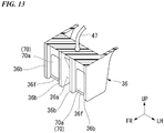
- the stopper-side terminals 70 are provided on the front sections of the side stoppers 36 (hereinafter, simply referred to as "the stoppers 36").
- the plurality of (in Fig. 13 , two) stopper-side terminals 70 are provided with an interval therebetween in the vehicle width direction.
- the stopper-side terminals 70 are provided on the left and right stoppers 36, respectively.
- the stopper-side terminals 70 extend in the upward/downward direction and each have a plate shape having a thickness in the forward/rearward direction.
- the stopper-side terminals 70 and the receiving-side terminals 80 face each other in the forward/rearward direction when the storage box 30 is mounted on the carrier 50.
- the stoppers 36 When seen in a left side view of Fig. 15(a) , the stoppers 36 each have an external form having a longitudinal width that is reduced downward. Concave escape sections 36a recessed to avoid partition walls 83 when the storage box 30 is mounted on the carrier 50 are provided in the stoppers 36. As shown in Fig. 13 , the two stopper-side terminals 70 are arranged on left and right sides via the concave escape sections 36a.
- the stoppers 36 include load receiving sections 36b configured to receive a load from the stopper receiving sections 56 before the stopper-side terminals 70 and the receiving-side terminals 80 are connected when the storage box 30 is mounted on the carrier 50.
- the load receiving sections 36b are disposed outward from the stopper-side terminals 70 in the vehicle width direction.
- the load receiving sections 36b protrude forward from installation surfaces 36f of the stopper-side terminals 70.
- a height (a thickness) of the stopper-side terminals 70 is smaller than that of protrusion ends of the load receiving sections 36b.
- the stopper-side terminals 70 are disposed further rearward (inward) than the protrusion ends of the load receiving sections 36b of the stoppers 36.
- One end of the cord 47 is connected to the stopper-side terminals 70. Further, the other end of the cord 47 is connected to the lid lamp 46 (see Fig. 5 ).
- the receiving-side terminals 80 are provided on rear sections of vertical walls 56a of the stopper receiving sections 56.
- the plurality of (in Fig. 14(b) , two) receiving-side terminals 80 are provided at an interval in the vehicle width direction.
- the receiving-side terminals 80 are provided in the left and right stopper receiving sections 56, respectively.
- the receiving-side terminals 80 are connected to the stopper-side terminals 70 when the storage box 30 is mounted on the carrier 50.
- the receiving-side terminals 80 are connected to the stopper-side terminals 70 and rub against the stopper-side terminals 70 when the storage box 30 is mounted on the carrier 50.
- the stopper-side terminals 70 and the receiving-side terminals 80 are configured to be connected by pushing the stoppers 36 into the stopper receiving sections 56 after the front hooks 33 are pushed into the hook receiving section 53 (see Fig. 16 ).
- the receiving-side terminals 80 When seen in a left side view of Fig. 15(b) , the receiving-side terminals 80 include bent sections 80a extending in the upward/downward direction and bent to protrude toward the stopper-side terminals 70. Contact portions between flat surface sections 70a of the stopper-side terminals 70 and the bent sections 80a of the receiving-side terminals 80 become contact sections of the terminals 70 and 80.
- the receiving-side terminals 80 are swingably attached to the vertical walls 56a. Upper end portions of the receiving-side terminals 80 are pivotable around a support shaft (not shown) extending in the vehicle width direction.
- Biasing members 82 configured to bias the receiving-side terminals 80 toward the stopper-side terminals 70 are attached to the receiving-side terminals 80.
- the biasing members 82 are coil springs.
- Portions of the receiving-side terminals 80 opposite to the stopper-side terminals 70 are connected to a battery (not shown) on the side of the vehicle body via the wiring 85.
- Vertical insertion holes 56h that open upward in the vicinity of the receiving-side terminals 80 are provided in the stopper receiving sections 56.
- the vertical insertion holes 56h communicate with introduction ports 56i (hereinafter, referred to as "stopper introduction ports 56i") of the stopper-side terminals 70 in the upward/downward direction.
- the partition walls 83 configured to divide accommodating spaces of the neighboring two receiving-side terminals 80 are provided on the vertical walls 56a of the stopper receiving sections 56.
- the partition walls 83 protrude rearward from the vertical walls 56a and extend upward and downward. Parts of protrusion edges 83 a of the partition walls 83 are formed along external forms of the receiving-side terminals 80.
- the protrusion edges 83a of the partition walls 83 are inclined such that a protrusion height increases going away from the introduction ports 56i of the stopper-side terminals 70 (downward).
- the protrusion edges 83a of the partition walls 83 are formed in a linear shape that is inclined to be disposed downward as it goes rearward.
- a protrusion height of the receiving-side terminals 80 is smaller than that of the protrusion edges 83a of the partition walls 83.
- the receiving-side terminals 80 are disposed further forward (inward) than the protrusion edges 83a of the partition walls 83 in the stopper receiving sections 56.
- lid members 90 swingably provided on the carrier 50 and configured to cover the stopper introduction ports 56i when the storage box 30 is not mounted on the carrier 50 may be provided on the stopper receiving sections 56.
- the lid members 90 include rectangular plate-shaped lid main bodies 91 configured to cover the stopper introduction ports 56i, hinge shafts 92 extending in the vehicle width direction and configured to pivotably support the lid main bodies 91, and locking claws 93 protruding from tips of the lid main bodies 91.
- the lid members 90 are normally biased by spring members (not shown) in an arrow K1 direction (see Fig. 15(a) ).
- Claw receiving sections 83c configured to receive the locking claws 93 are provided in upper end portions of the partition walls 83.
- the lid members 90 are pivoted against biasing forces of the spring members in an arrow K2 direction (see Fig. 15(b) ) when the storage box 30 is mounted on the carrier 50.
- escape grooves 83b recessed to avoid the locking claws 93 when the storage box 30 is mounted on the carrier 50 are provided in protrusion ends of the vertical walls 56a.
- the receiving-side terminals 80 (see Fig. 15 ) on the side of the carrier 50 and the stopper-side terminals 70 (see Fig. 15 ) on the side of the storage box 30 are connected to each other.
- the stopper receiving sections 56 receive the stoppers 36 after the front hooks 33 are pushed into the hook receiving section 53 (see Fig. 16 )
- the stopper-side terminals 70 and the receiving-side terminals 80 are connected to each other.
- the receiving-side terminals 80 are pivoted against biasing forces of biasing members 82 in an arrow K3 direction while being connected to the stopper-side terminals 70. Accordingly, electric power can be supplied to the electrical component on the side of the lid 32 (the lid lamp 46 shown in Fig. 5 ) from the battery (not shown) on the side of the vehicle body.
- the storage box 30 can be attached to the carrier 50.
- the storage box 30 can be removed from the carrier 50.
- the storage box power supply structure 25 of the embodiment includes the storage box 30, the carrier 50 configured to detachably mount the storage box 30 on the vehicle body, the stoppers 36 configured to position the storage box 30 on the carrier 50, the stopper receiving sections 56 configured to receive the stoppers 36, the stopper-side terminals 70 provided on the stoppers 36 and configured to supply electric power to the lid lamp 46, and the receiving-side terminals 80 provided on the stopper receiving sections 56, connected to the stopper-side terminals 70 when the storage box 30 is mounted on the carrier 50 and configured to rub against the stopper-side terminals 70.
- the receiving-side terminals 80 provided on the stopper receiving sections 56, connected to the stopper-side terminals 70 when the storage box 30 is mounted on the carrier 50 and configured to rub against the stopper-side terminals 70 are provided, the following effects are exhibited.
- Self-cleaning of the terminals 70 and 80 can be performed by friction when the stopper-side terminals 70 and the receiving-side terminals 80 are connected to each other. It is possible to remove the oxide films of the terminals 70 and 80 through self-cleaning of the terminals 70 and 80 or remove foreign substances such as sand bites or the like.
- the power supply structure is provided on the stopper receiving sections 56, there is no need to provide a novel power supply part on the bottom section of the storage box 30, and also there is no need to greatly change shapes of the storage box 30 and the carrier 50. Accordingly, self-cleaning of a power supply structure using a conventional structure can be actively performed according to an operation of attaching and detaching the storage box 30 while a novel power supply part is not provided in the storage box 30.
- stopper-side terminals 70 and the receiving-side terminals 80 face each other in the forward/rearward direction when the storage box 30 is mounted on the carrier 50, flexibility in the vehicle width direction can be absorbed by the stopper-side terminals 70 and the receiving-side terminals 80. Accordingly, variations at the connecting position to the terminals 70 and 80 can be absorbed. In addition, friction due to vibrations in the contact sections between the stopper-side terminals 70 and the receiving-side terminals 80 can be minimized.
- the biasing members 82 configured to bias the receiving-side terminals 80 toward the stopper-side terminals 70 are further provided, the stopper-side terminals 70 and the receiving-side terminals 80 can easily come into contact with each other.
- the receiving-side terminals 80 include the bent sections 80a that are bent to protrude toward the stopper-side terminals 70, the following effects are exhibited. In comparison with the case in which both of the stopper-side terminals 70 and the receiving-side terminals 80 are formed in a flat plate shape, the stopper-side terminals 70 and the receiving-side terminals 80 can easily come into contact with each other.
- the plurality of receiving-side terminals 80 are provided at an interval in the vehicle width direction, the following effects are exhibited. In comparison with the case in which only one receiving-side terminal 80 is provided, connection of the stopper-side terminals 70 and the receiving-side terminals 80 can be reliably performed. For example, when the plurality of stopper-side terminals 70 corresponding to the plurality of receiving-side terminals 80 are provided, they can be applied to various uses for a positive electrode terminal, a negative electrode terminal, a terminal for a stop lamp, and the like.
- the partition walls 83 configured to divide the accommodating spaces of the neighboring two receiving-side terminals 80 are further provided, it is possible to prevent the neighboring two receiving-side terminals 80 from coming in contact with each other.
- part of the protrusion edges 83a of the partition walls 83 are formed along external forms of the receiving-side terminals 80, it is possible to prevent the partition walls 83 from becoming obstacles when the stoppers 36 are pushed into the stopper receiving sections 56.
- the protrusion edges 83a of the partition walls 83 are inclined to increase a protrusion height as they are separated from the introduction ports 56i of the stopper-side terminals 70, the following effects are exhibited. It is possible for the partition walls 83 to increase rigidity of the stopper receiving sections 56 while the partition walls 83 are prevented from becoming obstacles when the stoppers 36 are pushed into the stopper receiving sections 56.
- the stoppers 36 are provided on the side of the storage box 30 and the stopper receiving sections 56 are provided on the side of the carrier 50, the following effects are exhibited.
- the stopper-side terminals 70 on the side of the storage box 30 and the receiving-side terminals 80 on the side of the carrier 50 are connected to each other, positioning of the terminals 70 and 80 can be easily performed.
- the vertical insertion holes 56h that open upward and downward in the vicinity of the stopper-side terminals 70 are provided in the stopper receiving sections 56, drainage can be performed through openings of the vertical insertion holes 56h.
- the storage box 30 is mounted on the carrier 50 when it's raining, rain water and the like can be prevented from being collected in the stopper receiving sections 56.
- the lid members 90 swingably provided on the carrier 50 and configured to cover the introduction ports 56i of the stopper-side terminals 70 when the storage box 30 is not mounted on the carrier 50 is further provided, the stopper receiving sections 56 are not exposed to the outside by the lid members 90. Accordingly, when the storage box 30 is not mounted on the carrier 50, it is possible to prevent foreign substances such as water, dust, and the like, from entering the stopper receiving sections 56.
- stoppers 36 include the load receiving sections 36b configured to receive a load from the stopper receiving sections 56 before the stopper-side terminals 70 and the receiving-side terminals 80 are connected when the storage box 30 is mounted on the carrier 50, it is possible to prevent an excessive load from being applied to the contact section.
- the stopper-side terminals 70 and the receiving-side terminals 80 are configured to be connected by pushing the stoppers 36 into the stopper receiving sections 56 after the hook 33 are pushed into the hook receiving section 53, the following effects are exhibited. Since the stopper-side terminals 70 and the receiving-side terminals 80 are connected after the hook 33 and the hook receiving section 53 are positioned, the stopper-side terminals 70 and the receiving-side terminals 80 can be easily connected.
- the pair of stoppers 36 are provided on left and right sides, the following effects are exhibited. Since the storage box 30 and the carrier 50 are positioned on left and right sides with good balance, in comparison with the case in which only one stopper 36 is provided, the stopper-side terminals 70 and the receiving-side terminals 80 can easily come into contact with each other.
- the storage box 30 may be provided on a front section of the vehicle or may be provided on a side portion of the vehicle (a side portion of the carrier 50).
- stopper-side terminals 70 are provided on the left and right stoppers 36, respectively, has been exemplarily described in the embodiment, there is no limitation thereto.
- the stopper-side terminals 70 may be provided on only one of the left and right stoppers 36. That is, the stopper-side terminals 70 may be formed on at least one of the left and right stoppers 36.
- the biasing members 82 configured to bias the receiving-side terminals 80 toward the stopper-side terminals 70 has been exemplarily described in the embodiment, there is no limitation thereto.
- the biasing member configured to bias the stopper-side terminals 70 toward the receiving-side terminals 80 may be provided. That is, a biasing member configured to bias at least one of the stopper-side terminals 70 and the receiving-side terminals 80 toward the other may be provided.
- biasing members 82 are the coil springs
- the biasing members 82 may be leaf springs.
- the receiving-side terminals 80 include the bent sections 80a that are bent to protrude toward the stopper-side terminals 70
- the stopper-side terminals 70 may include bent sections that are bent to protrude toward the receiving-side terminals 80. That is, at least one of the stopper-side terminals 70 and the receiving-side terminals 80 may include bent sections that are bent to protrude the other.
- the front hooks 33 each are formed in an L shape extending downward from the front lower section of the box main body 31 and then extending rearward
- the front hooks 33 may be formed in an L shape extending downward from the front lower section of the box main body 31 and then extending rearward.
- the electrical component may be another electrical component such as a USB charger, a solenoid, or the like, or may be other lighting devices than the lid lamp 46.
- a contact portion between a flat surface section 170a (see Fig. 17 ) of a stopper-side terminal 170 and a flat surface section 180a (see Fig. 18 ) of a receiving-side terminal 180 may be a contact section between the terminals 170 and 180.
- reference sign 136b designates load receiving sections that constitute left and right sidewalls of the stoppers 36.
- illustration of the lid members 90 or the like will be omitted.
- the stopper-side terminal 170 may include a longitudinal extension section 171 extending in the forward/rearward direction, and a downward extension section 172 having an L shape extending downward from a front end of the longitudinal extension section 171 to form the flat surface section 170a and then extending rearward.
- the longitudinal extension section 171 is attached to a bottom section of the box main body 31.
- a rear section of the longitudinal extension section 171 is connected to the lid lamp 46 (see Fig. 5 ) via the cord 47.
- the receiving-side terminal 180 may be formed in a C shape (a U shape) having the flat surface section 180a that is able to come in contact with the flat surface section 170a of the downward extension section 172.
- the biasing members 82 configured to bias the receiving-side terminal 180 toward the stopper-side terminal 170 are attached to the receiving-side terminal 180.
- the receiving-side terminals 80 are connected to a battery (not shown) on the side of the vehicle body via the wiring 85.
- the stopper-side terminal 170 and the receiving-side terminal 180 are connected.
- the receiving-side terminal 180 moves against the biasing force of the spring members 82 in an arrow K4 direction while being connected to the stopper-side terminal 170. Accordingly, electric power can be supplied from the battery (not shown) on the side of the vehicle body to the electrical component (the lid lamp 46 shown in Fig. 5 ) on the side of the lid 32.
- the receiving-side terminal 80 itself may be constituted by a biasing member such as a coil spring, a leaf spring, or the like. Accordingly, the number of parts can be reduced and reduction in costs can be achieved.
- a receiving-side terminal 280 having a leaf spring shape may be provided.
- the present invention is not limited to the embodiment, and for example, all vehicles on which a driver rides on the vehicle body are included as the saddles vehicle, and in addition to a motorcycle (including a motorized bicycle and a scooter-type vehicle), a three-wheeled vehicle (including a two-front-wheeled and one-rear-wheeled vehicle in addition to one-front-wheeled and two-rear-wheeled vehicle) is also included.
- the present invention may also be applicable to a four-wheeled vehicle such as an automobile or the like, in addition to the motorcycle.
Landscapes
- Engineering & Computer Science (AREA)
- Mechanical Engineering (AREA)
- Battery Mounting, Suspending (AREA)
- Automatic Cycles, And Cycles In General (AREA)
Abstract
Description
- The present invention relates to a storage box power supply structure for a saddled vehicle.
- Priority is claimed on Japanese Patent Application No.
2017-254991, filed December 28, 2017 - In the related art, a storage box power supply structure for a saddled vehicle including a storage box having electrical components therein and a carrier configured to detachably mount the storage box on a vehicle body is disclosed (for example, see Patent Document 1). Since the storage box is attached to the carrier, a carrier-side connector and a storage box-side connector are connected, and electric power can be supplied to the electrical component from a battery of a vehicle.
- Patent Document 1: Japanese Unexamined Patent Application, First Publication No.
2016-68766 - However, in Patent Document 1, in order to provide a power supply structure, a new power supply part (a box-side connector) is provided on a bottom section (a box-side facing section facing a carrier-side facing section) of a storage box, and it is necessary to greatly change shapes of the storage box and a carrier. In addition, in consideration of that the oxide film occurs on the terminal on the side of the storage box and the terminal on the side of the carrier or foreign substances such as sand bites or the like are adhered thereto, it is desired that self-cleaning can be actively performed according to an operation of attaching and detaching the storage box.
- An aspect of the present invention is directed to providing a storage box power supply structure for a saddled vehicle in which self-cleaning of a power supply structure using a conventional structure is actively performed according to an operation of attaching and detaching a storage box while a novel power supply part is not provided in the storage box.
- An aspect of the present invention has the following configurations.
- (1) A storage box power supply structure for a saddled vehicle according to an aspect of the present invention includes a storage box (30); a carrier (50) configured to detachably mount the storage box (30) on a vehicle body; a stopper (36) configured to position the storage box (30) on the carrier (50); a stopper receiving section (56) configured to receive the stopper (36); a stopper-side terminal (70) provided on the stopper (36) and configured to supply electric power to an electrical component (46); and a receiving-side terminal (80) provided on the stopper receiving section (56), connected to the stopper-side terminal (70) when the storage box (30) is mounted on the carrier (50) and configured to rub against the stopper-side terminal (70).
- (2) In the storage box power supply structure for a saddled vehicle according to the above-mentioned (1), the stopper-side terminal (70) and the receiving-side terminal (80) may face each other in a forward/rearward direction when the storage box (30) is mounted on the carrier (50).
- (3) The storage box power supply structure for a saddled vehicle according to the above-mentioned (1) or (2) may further include a biasing member (82) configured to bias at least one of the stopper-side terminal (70) and the receiving-side terminal (80) toward the other.
- (4) In the storage box power supply structure for a saddled vehicle according to any one of the above-mentioned (1) to (3), at least one of the stopper-side terminal (70) and the receiving-side terminal (80) may include a bent section (80a) bent to protrude toward the other.
- (5) In the storage box power supply structure for a saddled vehicle according to any one of the above-mentioned (1) to (4), the plurality of receiving-side terminals (80) may be provided at intervals in a vehicle width direction.
- (6) The storage box power supply structure for a saddled vehicle according to the above-mentioned (5) may further include a partition wall (83) configured to divide accommodating spaces of the neighboring two receiving-side terminals (80).
- (7) In the storage box power supply structure for a saddled vehicle according to the above-mentioned (6), at least a part of a protrusion edge (83a) of the partition wall (83) may be formed along an external form of the receiving-side terminal (80).
- (8) In the storage box power supply structure for a saddled vehicle according to the above-mentioned (6) or (7), the protrusion edge (83a) of the partition wall (83) may be inclined to increase a protrusion height as the protrusion edge (83a) becomes further away from an introduction port (56i) of the stopper-side terminal (70).
- (9) In the storage box power supply structure for a saddled vehicle according to any one of the above-mentioned (1) to (8), the stopper (36) may be provided on the side of the storage box (30), and the stopper receiving section (56) may be provided on the side of the carrier (50).
- (10) In the storage box power supply structure for a saddled vehicle according to the above-mentioned (9), a vertical insertion hole (56h) that opens upward and downward in the vicinity of the stopper-side terminal (70) may be formed in the stopper receiving section (56).
- (11) The storage box power supply structure for a saddled vehicle according to the above-mentioned (9) or (10) may further include a lid member (90) swingably provided on the carrier (50) and configured to cover an introduction port (56i) of the stopper-side terminal (70) when the storage box (30) is mounted on the carrier (50).
- (12) In the storage box power supply structure for a saddled vehicle according to any one of the above-mentioned (1) to (11), the stopper (36) may include a load receiving section (36b) configured to receive a load from the stopper receiving section (56) before the stopper-side terminal (70) and the receiving-side terminal (80) are connected when the storage box (30) is mounted on the carrier (50).
- (13) The storage box power supply structure for a saddled vehicle according to any one of the above-mentioned (1) to (12) may further include a hook (33) configured to connect the storage box (30) to the carrier (50); and a hook receiving section (53) configured to receive the hook (33), wherein the stopper-side terminal (70) and the receiving-side terminal (80) are configured to be connected by pushing the stopper (36) into the stopper receiving section (56) after the hook (33) is pushed into the hook receiving section (53).
- (14) In the storage box power supply structure for a saddled vehicle according to any one of the above-mentioned (1) to (13), the pair of stoppers (36) may be provided on left and right sides.
- According to the storage box power supply structure for a saddled vehicle according to the above-mentioned (1) of the present invention, since the receiving-side terminal provided on the stopper receiving section, connected to the stopper-side terminal when the storage box is mounted on the carrier and configured to rub against the stopper-side terminal is provided, the following effects are exhibited. Self-cleaning of the terminal can be performed by friction when the stopper-side terminal and the receiving-side terminal are connected. It is possible to remove an oxide film of the terminal or remove foreign substances such as sand bites or the like through self-cleaning of the terminal. In addition, since the power supply structure is provided on the stopper and the stopper receiving section, there is no need to provide a new power supply part on a bottom section of the storage box, and also there is no need to greatly change shapes of the storage box and the carrier. Accordingly, self-cleaning can be actively performed according to an operation of attaching and detaching the storage box using a power supply structure having a conventional structure without providing a new power supply part on the storage box.
- According to the storage box power supply structure for a saddled vehicle according to the above-mentioned (2) of the present invention, since the stopper-side terminal and the receiving-side terminal face each other in the forward/rearward direction when the storage box is mounted on the carrier, flexibility in the vehicle width direction can be absorbed by the stopper-side terminal and the receiving-side terminal. Accordingly, variations at the connecting position to the terminal can be absorbed. In addition, friction due to vibrations in the contact portion (hereinafter, referred to as "a contact section") between the stopper-side terminal and the receiving-side terminal can be minimized.
- According to the storage box power supply structure for a saddled vehicle of the above-mentioned (3) of the present invention, since the biasing member configured to bias at least one of the stopper-side terminal and the receiving-side terminal to the other is further provided, the stopper-side terminal and the receiving-side terminal can easily come into contact with each other.
- According to the storage box power supply structure for a saddled vehicle according to the above-mentioned (4) of the present invention, since at least one of the stopper-side terminal and the receiving-side terminal includes the bent section that is bent to protrude toward the other, the following effects are exhibited. In comparison with the case in which both of the stopper-side terminal and the receiving-side terminal are formed in a flat plate shape, the stopper-side terminal and the receiving-side terminal can easily come into contact with each other.
- According to the storage box power supply structure for a saddled vehicle according to the above-mentioned (5) of the present invention, since the plurality of receiving-side terminals are provided at intervals in the vehicle width direction, the following effects are exhibited. In comparison with the case in which only one receiving-side terminal is provided, connection between the stopper-side terminal and the receiving-side terminal can be reliably performed. For example, when the plurality of stopper-side terminals corresponding to the plurality of receiving-side terminals are provided, the terminals can be applied for various uses such as a positive electrode terminal, a negative electrode terminal, a terminal for a stop lamp, or the like.
- According to the storage box power supply structure for a saddled vehicle according to the above-mentioned (6) of the present invention, since the partition wall configured to divide the accommodating spaces of the neighboring two receiving-side terminals is further provided, it is possible to prevent the neighboring two receiving-side terminals from coming in contact with each other.
- According to the storage box power supply structure for a saddled vehicle according to the above-mentioned (7) of the present invention, since at least a part of the protrusion edge of the partition wall is formed along an external form of the receiving-side terminal, it is possible to prevent the partition wall from becoming an obstacle when the stopper is pushed into the stopper receiving section.
- According to the storage box power supply structure for a saddled vehicle according to the above-mentioned (8) of the present invention, since the protrusion edge of the partition wall is inclined to increase a protrusion height as it is separated from the introduction port of the stopper-side terminal, the following effects are exhibited. Rigidity of the stopper receiving section can be increased by the partition wall while preventing the partition wall from becoming an obstacle when the stopper is pushed into the stopper receiving section.
- According to the storage box power supply structure for a saddled vehicle according to the above-mentioned (9) of the present invention, since the stopper is provided on the side of the storage box and the stopper receiving section is provided on the side of the carrier, the following effects are exhibited. When the stopper-side terminal on the side of the storage box and the receiving-side terminal on the side of the carrier are connected, positioning of the terminal can be easily performed.
- According to the storage box power supply structure for a saddled vehicle according to the above-mentioned (10) of the present invention, since the vertical insertion hole that opens upward and downward in the vicinity of the stopper-side terminal is formed in the stopper receiving section, drainage can be performed through the opening of the vertical insertion hole. For example, even when the storage box is mounted on the carrier when it's raining, it is possible to prevent rain water or the like from being collected in the stopper receiving section.
- According to the storage box power supply structure for a saddled vehicle according to the above-mentioned (11) of the present invention, since the lid member swingably provided on the carrier and configured to cover the introduction port of the stopper-side terminal when the storage box is not mounted on the carrier, the stopper receiving section is not exposed to the outside by the lid member. Accordingly, when the storage box is not mounted on the carrier, it is possible to prevent foreign substances such as water, dust, and the like, from entering the stopper receiving section.
- According to the storage box power supply structure for a saddled vehicle according to the above-mentioned (12) of the present invention, since the stopper includes the load receiving section configured to receive a load from the stopper receiving section before the stopper-side terminal and the receiving-side terminal are connected when the storage box is mounted on the carrier, it is possible to prevent an excessive load from being applied to the contact section.
- According to the storage box power supply structure for a saddled vehicle according to the above-mentioned (13) of the present invention, since the stopper-side terminal and the receiving-side terminal are configured to be connected by pushing the stopper into the stopper receiving section after the hook is pushed into the hook receiving section, the following effects are exhibited. Since the stopper-side terminal and the receiving-side terminal are connected after they are positioned by the hook and the hook receiving section, the stopper-side terminal and the receiving-side terminal can be easily connected.
- According to the storage box power supply structure for a saddled vehicle according to the above-mentioned (14) of the present invention, since the pair of stoppers are provided on left and right sides, the following effects are exhibited. Since the storage box and the carrier are positioned on left and right sides with good balance, in comparison with the case in which only one stopper is provided, the stopper-side terminal and the receiving-side terminal can easily come into contact with each other.
-
-
Fig. 1 is a left side view of a motorcycle according to an embodiment. -
Fig. 2 is a left side view of a vehicle rear section of the motorcycle according to the embodiment. -
Fig. 3 is a front view of a storage box according to the embodiment. -
Fig. 4 is a bottom view of the storage box according to the embodiment. -
Fig. 5 is a perspective view showing the storage box according to the embodiment from below to the left. -
Fig. 6 is a perspective view of a vehicle rear section when the storage box according to the embodiment is removed from a carrier when seen from below to the left. -
Fig. 7 is a perspective view showing the carrier according to the embodiment from above to the left. -
Fig. 8 is a perspective view showing the carrier according to the embodiment from above to the front. -
Fig. 9 is a bottom view of the carrier according to the embodiment. -
Fig. 10 is a view including a cross section taken along line X-X inFig. 3 . -
Fig. 11 is a view including a cross section taken along line XI-XI inFig. 3 . -
Fig. 12 is a view including a cross section taken along line XII-XII inFig. 3 . -
Fig. 13 is a perspective view showing a stopper according to the embodiment from above to the left. -
Fig. 14 is a perspective view showing a stopper receiving section according to the embodiment from above to the left.Fig. 14(a) is a view showing a state in which the storage box is not mounted on the carrier.Fig. 14(b) is a view showing a state in which the storage box is mounted on the carrier. -
Fig. 15 is a view including cross sections of the stopper and the stopper receiving section according to the embodiment. -
Fig. 15(a) is a view showing a state in which the storage box is not mounted on the carrier.Fig. 15(b) is a view showing a state in which the storage box is mounted on the carrier. -
Fig. 16 is a view showing a process of an assembling procedure of the storage box according to the embodiment, including a cross section corresponding toFig. 12 . -
Fig. 17 is a perspective view showing a stopper according to a first variant of the embodiment from above to the left. -
Fig. 18 is a perspective view showing a stopper receiving section according to the first variant of the embodiment from above to the left, corresponding toFig. 14(b) . -
Fig. 19 is a view including cross sections of the stopper and the stopper receiving section according to the first variant of the embodiment.Fig. 19(a) is a view showing a state in which the storage box is not mounted on the carrier.Fig. 19(b) is a view showing a state in which the storage box is mounted on the carrier. -
Fig. 20 is a view including a cross section of a stopper receiving section according to a second variant of the embodiment. - Hereinafter, an embodiment of the present invention will be described with reference the accompanying drawings. Further, directions of forward, rearward, leftward, rightward, and so on, in the following description are the same as directions in a vehicle described below unless the context clearly indicates otherwise. In addition, in appropriate places in the drawings used in the following description, an arrow FR indicates a forward direction with respect to a vehicle, an arrow LH indicates a leftward direction with respect to the vehicle, and an arrow UP indicates an upward direction with respect to the vehicle. In addition, reference sign CL indicates a lateral centerline of a vehicle body.
-
Fig. 1 shows a unit swing motorcycle 1 as an example of a saddled vehicle. Referring toFig. 1 , the motorcycle 1 includes afront wheel 3 steered by ahandle 2, and arear wheel 4 driven by a power unit 5 including a power source. Hereinafter, the motorcycle may be simply referred to as "a vehicle." The motorcycle 1 of the embodiment is a scooter type vehicle havingstep floors 9 on which an occupant sitting on aseat 8 puts his/her legs. - Steering system parts including the
handle 2 and thefront wheel 3 are steerably pivoted by a head pipe (not shown) of a front end of a vehicle body frame. An outer circumference of the vehicle body frame is covered with avehicle body cover 10. InFig. 1 ,reference sign 6 indicates front forks. - A straddling
section 21 having a relatively low height in the vehicle is provided between thehandle 2 and theseat 8. Thestep floors 9 are provided on both of left and right sides of the straddlingsection 21. Acenter tunnel 22 extending forward and rearward to form a convex shape swelling upward is provided between the left andright step floors 9. - The
vehicle body cover 10 includes afront center cover 11 configured to cover a periphery of a head pipe from a forward side, left and right front side covers 12 configured to cover the periphery of the head pipe from a front outward side, a frontinner cover 14 configured to cover the periphery of the head pipe from a rearward side and configured to form a front section of thecenter tunnel 22 and left andright footrests 13, left and right floor front covers 15 continuous with lower rear sides of the left and right front side covers 12, left and right floor side covers 16 continuous with lower downward sides of the left and right floor front covers 15, a centerupper cover 17 continuous with a lower rearward side of the frontinner cover 14 and configured to form an upper surface of a rear section of thecenter tunnel 22, left and right center side covers 18 continuous with a rearward side of a lower section of the frontinner cover 14 and configured to form a side surface of a rear section of thecenter tunnel 22, and left and right rear side covers 19 continuous with rearward sides of the centerupper cover 17 and the left and right center side covers 18 and configured to cover the rear section of the vehicle body from a lateral side. - As shown in
Fig. 1 , a storage box power supply structure 25 (seeFig. 10 ) configured to supply electric power to electrical components provided in astorage box 30 or the like is provided in the rear section of the vehicle. The storage boxpower supply structure 25 includes thestorage box 30, acarrier 50 configured to detachably mount thestorage box 30 on the vehicle body, stoppers 36 (side stoppers 36 shown inFig. 5 ) configured to position thestorage box 30 on thecarrier 50, stopper receiving sections 56 (seeFig. 7 ) configured to receive thestoppers 36, stopper-side terminals 70 (seeFig. 13 ) provided on thestoppers 36 and configured to supply electric power to the electrical component 46 (thelid lamp 46 shown inFig. 2 ), and receiving-side terminals 80 (seeFig. 14 ) provided on thestopper receiving sections 56 and connected to the stopper-side terminals 70 when thestorage box 30 is mounted on thecarrier 50. - As shown in
Fig. 10 , thestorage box 30 is detachably attached to thecarrier 50. Thestorage box 30 can store articles such as a helmet and the like. Thestorage box 30 includes a boxmain body 31 formed in a box shape that opens upward, and alid 32 provided on an upper section of the boxmain body 31 to be opened and closed. - As shown in
Fig. 5 , the boxmain body 31 includes the pair of left and right front hooks 33 disposed on a front lower section of the boxmain body 31, arear hook 34 disposed at a center of a rear lower section of the boxmain body 31, a pair of left andright side stoppers 36 that face each other via therear hook 34, a pair of left andright leg sections 37 that face each other via the left andright side stoppers 36, and a plurality of (four shown in the drawing)elastic members 38 provided on a lower surface of the boxmain body 31. - As shown in
Fig. 3 , the pair of left and right front hooks 33 are disposed line-symmetrically with respect to a vehicle body lateral centerline CL as a symmetrical axis. Reinforcement sections of the left and right front hooks 33 are fixed to a front lower section of the boxmain body 31 by fastening members such as bolts or the like. As shown inFig. 11 , the left and right front hooks 33 are formed in an L shape extending downward from a front lower section of the boxmain body 31 and then extending to be bent rearward. When seen in a bottom view ofFig. 4 , rear ends of the left and right front hooks 33 are inclined to be disposed rearward as they go inward in a vehicle width direction. - As shown in
Fig. 10 , therear hook 34 is movable in conjunction with a pivoting operation of a key (not shown). For example, therear hook 34 is movable between an engaging position and an engagement releasing position with respect to a rearhook receiving section 54 in conjunction with an operation of a rear hook locking mechanism (not shown) in conjunction with a pivoting operation of the key. Therear hook 34 is formed in an L shape extending downward from a lower section of the boxmain body 31 and then extending to be bent rearward. - As shown in
Fig. 5 , the left andright side stoppers 36 and the left andright leg sections 37 protrude downward from a lower surface of the boxmain body 31. A protrusion height of each of the left andright side stoppers 36 is smaller than a protrusion height of each of the left andright leg sections 37. Further, the left andright side stoppers 36 function as a load receiving section configured to receive a load in the forward/rearward direction. - The four
elastic members 38 are disposed between the front and rear left and right front hooks 33 and left andright side stoppers 36. The fourelastic members 38 are disposed at intervals in the forward/rearward direction and the vehicle width direction. For example, theelastic members 38 are vibration-proof rubbers. - A
handle 42 is swingably attached to a rear section of the boxmain body 31. In a state inFig. 5 , thehandle 42 is in a receiving state in which thehandle 42 is received in aU-shaped groove 31u. In the receiving state, thehandle 42 is disposed along a rear surface of the boxmain body 31. - The
lid 32 is a box-shaped member configured to cover the boxmain body 31 from above. As shown inFig. 10 , thelid 32 is swingably attached to a front end portion of the boxmain body 31 via a rockingshaft 45. Thelid 32 can be locked by a lid locking mechanism (not shown). - The
lid lamp 46 serving as an electrical component is provided in a rear section of thelid 32. For example, thelid lamp 46 is a light emitting diode (LED). Thelid lamp 46 is connected to the hook-side terminals 70 (seeFig. 13 ) via a cord 47 (seeFig. 3 ) routed on an inner surface of thelid 32. - For example, a
portion 47a (seeFig. 3 ) of thecord 47 close to a front section of thelid 32 is preferably disposed parallel to the rocking shaft 45 (seeFig. 10 ). Accordingly, bending of thecord 47 can be avoided and disconnection thereof can be prevented. - For example, a
portion 47b (seeFig. 3 ) of thecord 47 close to a front section of the boxmain body 31 is preferably disposed along an inner wall of a corner section of the boxmain body 31. Accordingly, even when articles such as a helmet and the like are stored in thestorage box 30, it is possible to prevent thecord 47 from coming in contact with the articles such as a helmet or the like. - As shown in
Fig. 2 , thecarrier 50 is configured to detachably mount thestorage box 30 on the vehicle body. As shown inFig. 7 , thecarrier 50 includes a carriermain body 51 on which thestorage box 30 is mounted, and a pair of left and right grab rails 52 that are grabbed by an occupant. The carriermain body 51 and the left and right grab rails 52 are integrally formed of the same member. - As shown in
Fig. 8 , the carriermain body 51 has an external form having a width in the vehicle width direction that is reduced rearward. As shown inFig. 7 , the carriermain body 51 includes the pair of left and right front hook receiving sections 53 (seeFig. 11 ) configured to receive the left and right front hooks 33 (seeFig. 5 ), the rear hook receiving section 54 (seeFig. 10 ) configured to receive the rear hook 34 (seeFig. 5 ), a pair of left and right side insertion holes 56 (seeFig. 12 ) into which the left and right side stoppers 36 (seeFig. 5 ) are inserted, and aseat surface 57 which the elastic members 38 (seeFig. 5 ) abut, when the storage box 30 (seeFig. 2 ) is mounted on the carriermain body 51. - As shown in
Fig. 7 , vertical openingsections 51h that open upward and downward in the vicinity of the fronthook receiving sections 53 are provided in the front section of the carriermain body 51. When seen in a bottom view ofFig. 9 , thevertical opening sections 51h each have a long hole shape extending to be disposed rearward as it goes inward in the vehicle width direction. InFig. 6 ,reference sign 27 designates a tail light, andreference sign 28 designates a rear fender. - As shown in
Fig. 9 , the carriermain body 51 has a pair of left and right openingsections 51i formed in the central section of the carriermain body 51 to open upward and downward, and a frontsection insertion hole 51m formed in the front section of the carriermain body 51 to open upward and downward. - When seen in a bottom view of
Fig. 9 , the left and right openingsections 51i each have a long hole shape extending forward and rearward. When seen in a bottom view ofFig. 9 , the frontsection insertion hole 51m has a circular shape. The frontsection insertion hole 51m is an insertion hole through which a shaft section of a bolt configured to fix the carriermain body 51 to a rear frame 7 (seeFig. 10 ) is inserted. - As shown in
Fig. 8 , the left and right grab rails 52 extend forward from an outer end portion of the front section of the carriermain body 51 in the vehicle width direction. When seen in a left side view ofFig. 2 , upper edges of the left and right grab rails 52 are inclined to be disposed downward as they go forward. As shown inFig. 8 ,inward protrusion sections 52a protruding inward from front end portions of the left and right grab rails 52 in the vehicle width direction are provided on the left and right grab rails 52. Theinward protrusion sections 52a are fixed to the rear frame 7 (seeFig. 10 ) by fastening members (not shown) such as bolts or the like. - As shown in
Fig. 9 , a plurality ofribs 61 to 66 are provided on a lower section of thecarrier 50. The plurality ofribs 61 to 66 are afirst rib 61 extending forward and rearward to cross a forming section of the frontsection insertion hole 51m and the rearhook receiving section 54, asecond rib 62 extending in the vehicle width direction to cross the forming section of the frontsection insertion hole 51m and an outer edge of the carriermain body 51 in the vehicle width direction, athird rib 63 extending to cross the left and right fronthook receiving sections 53 and thesecond rib 62, afourth rib 64 extending to cross forming sections of thestopper receiving sections 56 and thesecond rib 62, afifth rib 65 extending to cross from outer edges of the left and right openingsections 51i in the vehicle width direction to an outer edge of the carriermain body 51 in the vehicle width direction, andsixth ribs 66 extending from front lower sections of the left and right grab rails 52 in the vehicle width direction. - As shown in
Fig. 13 , the stopper-side terminals 70 are provided on the front sections of the side stoppers 36 (hereinafter, simply referred to as "thestoppers 36"). The plurality of (inFig. 13 , two) stopper-side terminals 70 are provided with an interval therebetween in the vehicle width direction. The stopper-side terminals 70 are provided on the left andright stoppers 36, respectively. The stopper-side terminals 70 extend in the upward/downward direction and each have a plate shape having a thickness in the forward/rearward direction. As shown inFig. 15(b) , the stopper-side terminals 70 and the receiving-side terminals 80 face each other in the forward/rearward direction when thestorage box 30 is mounted on thecarrier 50. - In
Fig. 4 ,Fig. 5 ,Fig. 12 andFig. 16 , illustration of the stopper-side terminals 70 is omitted. - When seen in a left side view of
Fig. 15(a) , thestoppers 36 each have an external form having a longitudinal width that is reduced downward.Concave escape sections 36a recessed to avoidpartition walls 83 when thestorage box 30 is mounted on thecarrier 50 are provided in thestoppers 36. As shown inFig. 13 , the two stopper-side terminals 70 are arranged on left and right sides via theconcave escape sections 36a. - The
stoppers 36 includeload receiving sections 36b configured to receive a load from thestopper receiving sections 56 before the stopper-side terminals 70 and the receiving-side terminals 80 are connected when thestorage box 30 is mounted on thecarrier 50. Theload receiving sections 36b are disposed outward from the stopper-side terminals 70 in the vehicle width direction. - As shown in
Fig. 15(a) , theload receiving sections 36b protrude forward frominstallation surfaces 36f of the stopper-side terminals 70. A height (a thickness) of the stopper-side terminals 70 is smaller than that of protrusion ends of theload receiving sections 36b. The stopper-side terminals 70 are disposed further rearward (inward) than the protrusion ends of theload receiving sections 36b of thestoppers 36. - One end of the
cord 47 is connected to the stopper-side terminals 70. Further, the other end of thecord 47 is connected to the lid lamp 46 (seeFig. 5 ). - As shown in
Fig. 14(b) , the receiving-side terminals 80 are provided on rear sections ofvertical walls 56a of thestopper receiving sections 56. The plurality of (inFig. 14(b) , two) receiving-side terminals 80 are provided at an interval in the vehicle width direction. The receiving-side terminals 80 are provided in the left and rightstopper receiving sections 56, respectively. - As shown in
Fig. 15(b) , the receiving-side terminals 80 are connected to the stopper-side terminals 70 when thestorage box 30 is mounted on thecarrier 50. The receiving-side terminals 80 are connected to the stopper-side terminals 70 and rub against the stopper-side terminals 70 when thestorage box 30 is mounted on thecarrier 50. The stopper-side terminals 70 and the receiving-side terminals 80 are configured to be connected by pushing thestoppers 36 into thestopper receiving sections 56 after the front hooks 33 are pushed into the hook receiving section 53 (seeFig. 16 ). - In
Fig. 7 ,Fig. 8 ,Fig. 9 ,Fig. 12 andFig. 16 , illustration of the receiving-side terminals 80 will be omitted. - When seen in a left side view of
Fig. 15(b) , the receiving-side terminals 80 includebent sections 80a extending in the upward/downward direction and bent to protrude toward the stopper-side terminals 70. Contact portions betweenflat surface sections 70a of the stopper-side terminals 70 and thebent sections 80a of the receiving-side terminals 80 become contact sections of theterminals - The receiving-
side terminals 80 are swingably attached to thevertical walls 56a. Upper end portions of the receiving-side terminals 80 are pivotable around a support shaft (not shown) extending in the vehicle width direction. -
Biasing members 82 configured to bias the receiving-side terminals 80 toward the stopper-side terminals 70 are attached to the receiving-side terminals 80. For example, the biasingmembers 82 are coil springs. - Portions of the receiving-
side terminals 80 opposite to the stopper-side terminals 70 are connected to a battery (not shown) on the side of the vehicle body via thewiring 85. -
Vertical insertion holes 56h that open upward in the vicinity of the receiving-side terminals 80 are provided in thestopper receiving sections 56. Thevertical insertion holes 56h communicate withintroduction ports 56i (hereinafter, referred to as "stopper introduction ports 56i") of the stopper-side terminals 70 in the upward/downward direction. - As shown in
Fig. 14(b) , thepartition walls 83 configured to divide accommodating spaces of the neighboring two receiving-side terminals 80 are provided on thevertical walls 56a of thestopper receiving sections 56. As shown inFig. 15(a) , thepartition walls 83 protrude rearward from thevertical walls 56a and extend upward and downward. Parts of protrusion edges 83 a of thepartition walls 83 are formed along external forms of the receiving-side terminals 80. The protrusion edges 83a of thepartition walls 83 are inclined such that a protrusion height increases going away from theintroduction ports 56i of the stopper-side terminals 70 (downward). - When seen in a left side view of
Fig. 15(a) , the protrusion edges 83a of thepartition walls 83 are formed in a linear shape that is inclined to be disposed downward as it goes rearward. A protrusion height of the receiving-side terminals 80 is smaller than that of the protrusion edges 83a of thepartition walls 83. The receiving-side terminals 80 are disposed further forward (inward) than the protrusion edges 83a of thepartition walls 83 in thestopper receiving sections 56. - As shown in
Fig. 14(a) ,lid members 90 swingably provided on thecarrier 50 and configured to cover thestopper introduction ports 56i when thestorage box 30 is not mounted on thecarrier 50 may be provided on thestopper receiving sections 56. - The
lid members 90 include rectangular plate-shaped lidmain bodies 91 configured to cover thestopper introduction ports 56i, hingeshafts 92 extending in the vehicle width direction and configured to pivotably support the lidmain bodies 91, and lockingclaws 93 protruding from tips of the lidmain bodies 91. - The
lid members 90 are normally biased by spring members (not shown) in an arrow K1 direction (seeFig. 15(a) ). Claw receivingsections 83c configured to receive the lockingclaws 93 are provided in upper end portions of thepartition walls 83. Thelid members 90 are pivoted against biasing forces of the spring members in an arrow K2 direction (seeFig. 15(b) ) when thestorage box 30 is mounted on thecarrier 50. As shown inFig. 14(b) , escapegrooves 83b recessed to avoid the lockingclaws 93 when thestorage box 30 is mounted on thecarrier 50 are provided in protrusion ends of thevertical walls 56a. - As shown in
Fig. 2 , since thestorage box 30 is attached to thecarrier 50, the receiving-side terminals 80 (seeFig. 15 ) on the side of thecarrier 50 and the stopper-side terminals 70 (seeFig. 15 ) on the side of thestorage box 30 are connected to each other. Specifically, as shown inFig. 15 , since thestopper receiving sections 56 receive thestoppers 36 after the front hooks 33 are pushed into the hook receiving section 53 (seeFig. 16 ), the stopper-side terminals 70 and the receiving-side terminals 80 are connected to each other. Here, the receiving-side terminals 80 are pivoted against biasing forces of biasingmembers 82 in an arrow K3 direction while being connected to the stopper-side terminals 70. Accordingly, electric power can be supplied to the electrical component on the side of the lid 32 (thelid lamp 46 shown inFig. 5 ) from the battery (not shown) on the side of the vehicle body. - Hereinafter, an example of a procedure of attaching the
storage box 30 to thecarrier 50 will be described. - For example, when the
storage box 30 is attached to thecarrier 50, a procedure of the following (1) to (5) is performed. - (1) First, the
handle 42 is lifted, and akey cylinder 41 is exposed to the outside. - (2) Next, a key is inserted into the
key cylinder 41 and pivoted clockwise, and locking of the boxmain body 31 is released. - (3) Next, the
storage box 30 is mounted on thecarrier 50.
Specifically, as shown inFig. 16 , the front hooks 33 are pushed into the fronthook receiving sections 53 and positioned. After that, therear hook 34 is pushed into the rear hook receiving section 54 (seeFig. 10 ) while thestoppers 36 are pushed into the stopper receiving sections 56 (seeFig. 15 ). - (4) Next, the key is pivoted counterclockwise and the box
main body 31 is locked, and then, the key is removed. - (5) Next, the
handle 42 is received in theU-shaped groove 31u. - According to the above-mentioned procedure, the
storage box 30 can be attached to thecarrier 50. - Hereinafter, an example of a procedure of removing the
storage box 30 from thecarrier 50 will be described. - For example, when the
storage box 30 is removed from thecarrier 50, a procedure of the following (1) to (5) is performed. - (1) First, the
handle 42 is lifted, and a box mainbody unlocking button 40 and thekey cylinder 41 are exposed to the outside. - (2) The key is inserted into the
key cylinder 41 and pivoted clockwise, and locking of the boxmain body 31 is released. - (3) Next, the box main
body unlocking button 40 is pushed, and thestorage box 30 is removed from thecarrier 50. - (4) Next, the key is pivoted counterclockwise and the box
main body 31 is locked, and then, the key is removed. - (5) Next, the
handle 42 is received in theU-shaped groove 31u. - According to the above-mentioned procedure, the
storage box 30 can be removed from thecarrier 50. - As described above, the storage box
power supply structure 25 of the embodiment includes thestorage box 30, thecarrier 50 configured to detachably mount thestorage box 30 on the vehicle body, thestoppers 36 configured to position thestorage box 30 on thecarrier 50, thestopper receiving sections 56 configured to receive thestoppers 36, the stopper-side terminals 70 provided on thestoppers 36 and configured to supply electric power to thelid lamp 46, and the receiving-side terminals 80 provided on thestopper receiving sections 56, connected to the stopper-side terminals 70 when thestorage box 30 is mounted on thecarrier 50 and configured to rub against the stopper-side terminals 70. - According to this configuration, since the receiving-
side terminals 80 provided on thestopper receiving sections 56, connected to the stopper-side terminals 70 when thestorage box 30 is mounted on thecarrier 50 and configured to rub against the stopper-side terminals 70 are provided, the following effects are exhibited. Self-cleaning of theterminals side terminals 70 and the receiving-side terminals 80 are connected to each other. It is possible to remove the oxide films of theterminals terminals stopper receiving sections 56, there is no need to provide a novel power supply part on the bottom section of thestorage box 30, and also there is no need to greatly change shapes of thestorage box 30 and thecarrier 50. Accordingly, self-cleaning of a power supply structure using a conventional structure can be actively performed according to an operation of attaching and detaching thestorage box 30 while a novel power supply part is not provided in thestorage box 30. - In addition, in the embodiment, since the stopper-
side terminals 70 and the receiving-side terminals 80 face each other in the forward/rearward direction when thestorage box 30 is mounted on thecarrier 50, flexibility in the vehicle width direction can be absorbed by the stopper-side terminals 70 and the receiving-side terminals 80. Accordingly, variations at the connecting position to theterminals side terminals 70 and the receiving-side terminals 80 can be minimized. - In addition, in the embodiment, since the biasing
members 82 configured to bias the receiving-side terminals 80 toward the stopper-side terminals 70 are further provided, the stopper-side terminals 70 and the receiving-side terminals 80 can easily come into contact with each other. - In addition, in the embodiment, since the receiving-
side terminals 80 include thebent sections 80a that are bent to protrude toward the stopper-side terminals 70, the following effects are exhibited. In comparison with the case in which both of the stopper-side terminals 70 and the receiving-side terminals 80 are formed in a flat plate shape, the stopper-side terminals 70 and the receiving-side terminals 80 can easily come into contact with each other. - In addition, in the embodiment, since the plurality of receiving-
side terminals 80 are provided at an interval in the vehicle width direction, the following effects are exhibited. In comparison with the case in which only one receiving-side terminal 80 is provided, connection of the stopper-side terminals 70 and the receiving-side terminals 80 can be reliably performed. For example, when the plurality of stopper-side terminals 70 corresponding to the plurality of receiving-side terminals 80 are provided, they can be applied to various uses for a positive electrode terminal, a negative electrode terminal, a terminal for a stop lamp, and the like. - In addition, in the embodiment, since the
partition walls 83 configured to divide the accommodating spaces of the neighboring two receiving-side terminals 80 are further provided, it is possible to prevent the neighboring two receiving-side terminals 80 from coming in contact with each other. - In addition, in the embodiment, since part of the protrusion edges 83a of the
partition walls 83 are formed along external forms of the receiving-side terminals 80, it is possible to prevent thepartition walls 83 from becoming obstacles when thestoppers 36 are pushed into thestopper receiving sections 56. - In addition, in the embodiment, since the protrusion edges 83a of the
partition walls 83 are inclined to increase a protrusion height as they are separated from theintroduction ports 56i of the stopper-side terminals 70, the following effects are exhibited. It is possible for thepartition walls 83 to increase rigidity of thestopper receiving sections 56 while thepartition walls 83 are prevented from becoming obstacles when thestoppers 36 are pushed into thestopper receiving sections 56. - In addition, in the embodiment, since the
stoppers 36 are provided on the side of thestorage box 30 and thestopper receiving sections 56 are provided on the side of thecarrier 50, the following effects are exhibited. When the stopper-side terminals 70 on the side of thestorage box 30 and the receiving-side terminals 80 on the side of thecarrier 50 are connected to each other, positioning of theterminals - In addition, in the embodiment, since the
vertical insertion holes 56h that open upward and downward in the vicinity of the stopper-side terminals 70 are provided in thestopper receiving sections 56, drainage can be performed through openings of thevertical insertion holes 56h. For example, even though thestorage box 30 is mounted on thecarrier 50 when it's raining, rain water and the like can be prevented from being collected in thestopper receiving sections 56. - In addition, in the embodiment, since the
lid members 90 swingably provided on thecarrier 50 and configured to cover theintroduction ports 56i of the stopper-side terminals 70 when thestorage box 30 is not mounted on thecarrier 50 is further provided, thestopper receiving sections 56 are not exposed to the outside by thelid members 90. Accordingly, when thestorage box 30 is not mounted on thecarrier 50, it is possible to prevent foreign substances such as water, dust, and the like, from entering thestopper receiving sections 56. - In addition, in the embodiment, since the
stoppers 36 include theload receiving sections 36b configured to receive a load from thestopper receiving sections 56 before the stopper-side terminals 70 and the receiving-side terminals 80 are connected when thestorage box 30 is mounted on thecarrier 50, it is possible to prevent an excessive load from being applied to the contact section. - In addition, in the embodiment, since the stopper-
side terminals 70 and the receiving-side terminals 80 are configured to be connected by pushing thestoppers 36 into thestopper receiving sections 56 after thehook 33 are pushed into thehook receiving section 53, the following effects are exhibited. Since the stopper-side terminals 70 and the receiving-side terminals 80 are connected after thehook 33 and thehook receiving section 53 are positioned, the stopper-side terminals 70 and the receiving-side terminals 80 can be easily connected. - In addition, in the embodiment, since the pair of
stoppers 36 are provided on left and right sides, the following effects are exhibited. Since thestorage box 30 and thecarrier 50 are positioned on left and right sides with good balance, in comparison with the case in which only onestopper 36 is provided, the stopper-side terminals 70 and the receiving-side terminals 80 can easily come into contact with each other. - Further, while the example in which the
storage box 30 is provided on the rear section of the vehicle has been exemplarily described in the embodiment, there is no limitation thereto. For example, thestorage box 30 may be provided on a front section of the vehicle or may be provided on a side portion of the vehicle (a side portion of the carrier 50). - In addition, while the example in which the stopper-
side terminals 70 are provided on the left andright stoppers 36, respectively, has been exemplarily described in the embodiment, there is no limitation thereto. For example, the stopper-side terminals 70 may be provided on only one of the left andright stoppers 36. That is, the stopper-side terminals 70 may be formed on at least one of the left andright stoppers 36. - In addition, while the case in which the biasing
members 82 configured to bias the receiving-side terminals 80 toward the stopper-side terminals 70 is provided has been exemplarily described in the embodiment, there is no limitation thereto. For example, the biasing member configured to bias the stopper-side terminals 70 toward the receiving-side terminals 80 may be provided. That is, a biasing member configured to bias at least one of the stopper-side terminals 70 and the receiving-side terminals 80 toward the other may be provided. - In addition, while the example in which the biasing
members 82 are the coil springs has been described in the embodiment, there is no limitation thereto. For example, the biasingmembers 82 may be leaf springs. - In addition, while the example in which the receiving-
side terminals 80 include thebent sections 80a that are bent to protrude toward the stopper-side terminals 70 has been described in the embodiment, there is no limitation thereto. For example, the stopper-side terminals 70 may include bent sections that are bent to protrude toward the receiving-side terminals 80. That is, at least one of the stopper-side terminals 70 and the receiving-side terminals 80 may include bent sections that are bent to protrude the other. - In addition, while the example in which parts of the protrusion edges 83a of the
partition walls 83 are formed along external forms of the receiving-side terminals 80 has been exemplarily described in the embodiment, there is no limitation thereto. For example, all of the protrusion edges 83a of thepartition walls 83 may be formed along external forms of the receiving-side terminals 80. That is, at least parts of the protrusion edges 83a of thepartition walls 83 may be formed along external forms of the receiving-side terminals 80. - In addition, while the example in which the pair of
stoppers 36 are provided on left and right sides has been exemplarily described in the embodiment, there is no limitation thereto. For example, only onestopper 36 may be provided or three ormore stoppers 36 may be provided. - In addition, while the example in which the front hooks 33 each are formed in an L shape extending downward from the front lower section of the box
main body 31 and then extending rearward has been exemplarily described in the embodiment, there is no limitation thereto. For example, the front hooks 33 may be formed in an L shape extending downward from the front lower section of the boxmain body 31 and then extending rearward. - In addition, while the example in which the pair of front hooks 33 are provided on left and rights has been exemplarily described in the embodiment, there is no limitation thereto. For example, only one
front hook 33 may be provided or three or more front hooks 33 may be provided. - In addition, while the example in which the
lid lamp 46 is provided as the electrical component has been exemplarily described in the embodiment, there is no limitation thereto. For example, the electrical component may be another electrical component such as a USB charger, a solenoid, or the like, or may be other lighting devices than thelid lamp 46. - In addition, while the example in which the contact portions between the
flat surface sections 70a of the stopper-side terminals 70 and thebent sections 80a of the receiving-side terminals 80 become the contact sections between theterminals flat surface section 170a (seeFig. 17 ) of a stopper-side terminal 170 and aflat surface section 180a (seeFig. 18 ) of a receiving-side terminal 180 may be a contact section between theterminals Fig. 17 ,reference sign 136b designates load receiving sections that constitute left and right sidewalls of thestoppers 36. InFig. 17 to Fig. 19 , illustration of thelid members 90 or the like will be omitted. - For example, as shown in
Fig. 19(a) , the stopper-side terminal 170 may include alongitudinal extension section 171 extending in the forward/rearward direction, and adownward extension section 172 having an L shape extending downward from a front end of thelongitudinal extension section 171 to form theflat surface section 170a and then extending rearward. Thelongitudinal extension section 171 is attached to a bottom section of the boxmain body 31. A rear section of thelongitudinal extension section 171 is connected to the lid lamp 46 (seeFig. 5 ) via thecord 47. - The receiving-
side terminal 180 may be formed in a C shape (a U shape) having theflat surface section 180a that is able to come in contact with theflat surface section 170a of thedownward extension section 172. The biasingmembers 82 configured to bias the receiving-side terminal 180 toward the stopper-side terminal 170 are attached to the receiving-side terminal 180. The receiving-side terminals 80 are connected to a battery (not shown) on the side of the vehicle body via thewiring 85. - As shown in
Fig. 19(b) , since thestopper receiving sections 56 receive thestoppers 36 after the front hooks 33 are received in the hook receiving sections 53 (seeFig. 16 ), the stopper-side terminal 170 and the receiving-side terminal 180 are connected. Here, the receiving-side terminal 180 moves against the biasing force of thespring members 82 in an arrow K4 direction while being connected to the stopper-side terminal 170. Accordingly, electric power can be supplied from the battery (not shown) on the side of the vehicle body to the electrical component (thelid lamp 46 shown inFig. 5 ) on the side of thelid 32. - In addition, while the example in which the biasing
members 82 configured to bias the receiving-side terminals 80 toward the stopper-side terminals 70 are attached to the receiving-side terminals 80 has been exemplarily described in the embodiment, there is no limitation thereto. For example, the receiving-side terminal 80 itself may be constituted by a biasing member such as a coil spring, a leaf spring, or the like. Accordingly, the number of parts can be reduced and reduction in costs can be achieved. For example, as shown inFig. 20 , a receiving-side terminal 280 having a leaf spring shape may be provided. - In addition, the present invention is not limited to the embodiment, and for example, all vehicles on which a driver rides on the vehicle body are included as the saddles vehicle, and in addition to a motorcycle (including a motorized bicycle and a scooter-type vehicle), a three-wheeled vehicle (including a two-front-wheeled and one-rear-wheeled vehicle in addition to one-front-wheeled and two-rear-wheeled vehicle) is also included. In addition, the present invention may also be applicable to a four-wheeled vehicle such as an automobile or the like, in addition to the motorcycle.
- Then, the configuration of the embodiment is an example of the present invention, and various modifications may be made without departing from the spirit of the present invention, for example, substitution of the components of the embodiment with known components, or the like.
-
- 1
- Motorcycle (saddled vehicle)
- 25
- Storage box power supply structure
- 30
- Storage box
- 33
- Front hook (hook)
- 36
- Side stopper (stopper)
- 36b
- Load receiving section
- 46
- Lid lamp (electrical component)
- 50
- Carrier
- 53
- Front hook receiving section (hook receiving section)
- 53h
- Rearward opening section
- 56
- Stopper receiving section
- 56h
- Vertical insertion hole
- 56i
- Introduction port
- 70
- Stopper-side terminal
- 80
- Receiving-side terminal
- 80a
- Bent section
- 82
- Biasing member
- 83
- Partition wall
- 83a
- Protrusion edge
- 90
- Lid member
Claims (14)
- A storage box power supply structure for a saddled vehicle, comprising:a storage box (30);a carrier (50) configured to detachably mount the storage box (30) on a vehicle body;a stopper (36) configured to position the storage box (30) on the carrier (50);a stopper receiving section (56) configured to receive the stopper (36);a stopper-side terminal (70) provided on the stopper (36) and configured to supply electric power to an electrical component (46); anda receiving-side terminal (80) provided on the stopper receiving section (56), connected to the stopper-side terminal (70) when the storage box (30) is mounted on the carrier (50) and configured to rub against the stopper-side terminal (70).
- The storage box power supply structure for a saddled vehicle according to claim 1, wherein the stopper-side terminal (70) and the receiving-side terminal (80) face each other in a forward/rearward direction when the storage box (30) is mounted on the carrier (50).
- The storage box power supply structure for a saddled vehicle according to claim 1 or 2, further comprising a biasing member (82) configured to bias at least one of the stopper-side terminal (70) and the receiving-side terminal (80) toward the other.
- The storage box power supply structure for a saddled vehicle according to any one of claims 1 to 3, wherein at least one of the stopper-side terminal (70) and the receiving-side terminal (80) comprises a bent section (80a) bent to protrude toward the other.
- The storage box power supply structure for a saddled vehicle according to any one of claims 1 to 4, wherein the plurality of receiving-side terminals (80) are provided at intervals in a vehicle width direction.
- The storage box power supply structure for a saddled vehicle according to claim 5, further comprising a partition wall (83) configured to divide accommodating spaces of the neighboring two receiving-side terminals (80).
- The storage box power supply structure for a saddled vehicle according to claim 6, wherein at least a part of a protrusion edge (83a) of the partition wall (83) is formed along an external form of the receiving-side terminal (80).
- The storage box power supply structure for a saddled vehicle according to claim 6 or 7, wherein the protrusion edge (83a) of the partition wall (83) is inclined to increase a protrusion height as the protrusion edge (83a) becomes further away from an introduction port (56i) of the stopper-side terminal (70).
- The storage box power supply structure for a saddled vehicle according to any one of claims 1 to 8, wherein the stopper (36) is provided on the side of the storage box (30), and
the stopper receiving section (56) is provided on the side of the carrier (50). - The storage box power supply structure for a saddled vehicle according to claim 9, wherein a vertical insertion hole (56h) that opens upward and downward in the vicinity of the stopper-side terminal (70) is formed in the stopper receiving section (56).
- The storage box power supply structure for a saddled vehicle according to claim 9 or 10, further comprising a lid member (90) swingably provided on the carrier (50) and configured to cover an introduction port (56i) of the stopper-side terminal (70) when the storage box (30) is mounted on the carrier (50).
- The storage box power supply structure for a saddled vehicle according to any one of claims 1 to 11, wherein the stopper (36) comprises a load receiving section (36b) configured to receive a load from the stopper receiving section (56) before the stopper-side terminal (70) and the receiving-side terminal (80) are connected when the storage box (30) is mounted on the carrier (50).
- The storage box power supply structure for a saddled vehicle according to any one of claims 1 to 12, further comprising:a hook (33) configured to connect the storage box (30) to the carrier (50); anda hook receiving section (53) configured to receive the hook (33),wherein the stopper-side terminal (70) and the receiving-side terminal (80) are configured to be connected by pushing the stopper (36) into the stopper receiving section (56) after the hook (33) is pushed into the hook receiving section (53).
- The storage box power supply structure for a saddled vehicle according to any one of claims 1 to 13, wherein the pair of stoppers (36) are provided on left and right sides.
Applications Claiming Priority (2)
| Application Number | Priority Date | Filing Date | Title |
|---|---|---|---|
| JP2017254991 | 2017-12-28 | ||
| PCT/JP2018/034429 WO2019130678A1 (en) | 2017-12-28 | 2018-09-18 | Storage box power supply structure for saddle-type vehicle |
Publications (3)
| Publication Number | Publication Date |
|---|---|
| EP3733491A1 true EP3733491A1 (en) | 2020-11-04 |
| EP3733491A4 EP3733491A4 (en) | 2021-02-24 |
| EP3733491B1 EP3733491B1 (en) | 2023-11-22 |
Family
ID=67066947
Family Applications (1)
| Application Number | Title | Priority Date | Filing Date |
|---|---|---|---|
| EP18894890.5A Active EP3733491B1 (en) | 2017-12-28 | 2018-09-18 | Storage box power supply structure for saddle-type vehicle |
Country Status (4)
| Country | Link |
|---|---|
| US (1) | US11167814B2 (en) |
| EP (1) | EP3733491B1 (en) |
| JP (1) | JP6873277B2 (en) |
| WO (1) | WO2019130678A1 (en) |
Families Citing this family (1)
| Publication number | Priority date | Publication date | Assignee | Title |
|---|---|---|---|---|
| TWI698367B (en) * | 2019-10-31 | 2020-07-11 | 光陽工業股份有限公司 | Locomotive luggage |
Family Cites Families (19)
| Publication number | Priority date | Publication date | Assignee | Title |
|---|---|---|---|---|
| CN2141789Y (en) * | 1992-09-10 | 1993-09-08 | 吴式南 | Dismountable rearmounted box device for cycle |
| FR2703844B1 (en) | 1993-04-09 | 1995-05-24 | Sepm | Electrical connector and more specifically charging connector. |
| JP3662659B2 (en) * | 1996-02-23 | 2005-06-22 | 朝日電装株式会社 | Crimp sliding switch |
| IT243471Y1 (en) * | 1997-05-30 | 2002-03-04 | Galter Srl | LIGHTING DEVICE FOR SUITCASE-FLAT CASE COMPLEX |
| EP1078848A1 (en) * | 1999-08-27 | 2001-02-28 | Giuseppe Visenzi | Motorbike transport case comprising electric equipment |
| CN2863609Y (en) * | 2006-01-10 | 2007-01-31 | 伍贻杰 | Electric bicycle battery case connecting piece |
| ITMI20080211A1 (en) * | 2008-02-11 | 2009-08-12 | Givi Srl | "SUITCASE FOR MOTORCYCLES WITH EASY OPENING DEVICE" |
| CN102267515B (en) * | 2010-06-03 | 2013-03-06 | 耀马车业(中国)有限公司 | Novel electric vehicle shelf device |
| JP5594229B2 (en) * | 2011-05-27 | 2014-09-24 | スズキ株式会社 | Scooter type vehicle |
| KR200460263Y1 (en) * | 2011-11-29 | 2012-05-16 | 주식회사 제이아이씨 | Motorcycle tool box of power supply |
| JP2013129348A (en) * | 2011-12-22 | 2013-07-04 | Yamaha Motor Co Ltd | Straddle type electric vehicle |
| ES2674655T3 (en) | 2012-02-09 | 2018-07-03 | Honda Motor Co., Ltd. | Power supply device terminal base for electric vehicle |
| JP5794636B2 (en) * | 2012-02-20 | 2015-10-14 | 本田技研工業株式会社 | Electric vehicle power supply terminal block |
| IN2014CN02362A (en) * | 2012-03-02 | 2015-06-19 | Honda Motor Co Ltd | |
| DE202013002458U1 (en) * | 2013-03-14 | 2013-04-18 | Ortlieb Sportartikel Gmbh | Adapter for attaching bags or containers to rod parts of bicycles |
| CN104903184B (en) | 2013-03-29 | 2017-08-04 | 本田技研工业株式会社 | The power delivering structure of Straddle type vehicle |
| CN105705408A (en) | 2013-11-06 | 2016-06-22 | 雅马哈发动机株式会社 | Saddle-type electric vehicle |
| JP2016028920A (en) * | 2014-07-25 | 2016-03-03 | 本田技研工業株式会社 | Rear carrier of saddle-riding type vehicle |
| JP6113129B2 (en) * | 2014-09-30 | 2017-04-12 | 本田技研工業株式会社 | Saddle and additional storage boxes for saddle vehicles |
-
2018
- 2018-09-18 US US16/957,395 patent/US11167814B2/en active Active
- 2018-09-18 WO PCT/JP2018/034429 patent/WO2019130678A1/en unknown
- 2018-09-18 EP EP18894890.5A patent/EP3733491B1/en active Active
- 2018-09-18 JP JP2019562747A patent/JP6873277B2/en active Active
Also Published As
| Publication number | Publication date |
|---|---|
| WO2019130678A1 (en) | 2019-07-04 |
| EP3733491A4 (en) | 2021-02-24 |
| US11167814B2 (en) | 2021-11-09 |
| US20200324843A1 (en) | 2020-10-15 |
| JP6873277B2 (en) | 2021-05-19 |
| EP3733491B1 (en) | 2023-11-22 |
| JPWO2019130678A1 (en) | 2020-09-24 |
Similar Documents
| Publication | Publication Date | Title |
|---|---|---|
| JP5965055B2 (en) | Power supply structure for saddle-ride type vehicles | |
| EP2703265B1 (en) | Saddle type vehicle | |
| US9434436B1 (en) | Rear structure for saddle-ride type vehicle | |
| US8845154B2 (en) | Motorcycle | |
| TWI462372B (en) | Battery unit | |
| JP5732293B2 (en) | Rear fender structure of motorcycle | |
| US11554826B2 (en) | Storage box power supply structure for saddled vehicle | |
| EP3733491B1 (en) | Storage box power supply structure for saddle-type vehicle | |
| US9409615B2 (en) | Motorcycle | |
| EP2894087B1 (en) | Straddle-type vehicle | |
| JP6133111B2 (en) | Battery arrangement structure for saddle-ride type vehicles | |
| JP4720482B2 (en) | Motorcycle frame cover | |
| JP2009227228A (en) | Vehicle | |
| JP2019119333A (en) | Storage box power supply structure of saddle-riding type vehicle | |
| EP0921059A1 (en) | A safety fixing seat structure for bicycle fender | |
| JP2008080987A (en) | Vehicle flasher device and vehicle | |
| EP2878523B1 (en) | Straddle-type vehicle | |
| JP7373535B2 (en) | saddle type vehicle | |
| JP5970968B2 (en) | Saddle-type vehicle storage structure | |
| EP2500247B1 (en) | Saddlebag attachment structure for saddle riding type vehicle | |
| JP2018052457A (en) | Saddle-riding type vehicle | |
| JP2007045294A (en) | Battery box | |
| JP2024057283A (en) | Battery and saddle-type vehicle | |
| JP6383622B2 (en) | Storage structure for locking device of saddle riding type vehicle | |
| BR102015024630A2 (en) | saddle type driving vehicle |
Legal Events
| Date | Code | Title | Description |
|---|---|---|---|
| STAA | Information on the status of an ep patent application or granted ep patent |
Free format text: STATUS: THE INTERNATIONAL PUBLICATION HAS BEEN MADE |
|
| PUAI | Public reference made under article 153(3) epc to a published international application that has entered the european phase |
Free format text: ORIGINAL CODE: 0009012 |
|
| STAA | Information on the status of an ep patent application or granted ep patent |
Free format text: STATUS: REQUEST FOR EXAMINATION WAS MADE |
|
| 17P | Request for examination filed |
Effective date: 20200625 |
|
| AK | Designated contracting states |
Kind code of ref document: A1 Designated state(s): AL AT BE BG CH CY CZ DE DK EE ES FI FR GB GR HR HU IE IS IT LI LT LU LV MC MK MT NL NO PL PT RO RS SE SI SK SM TR |
|
| AX | Request for extension of the european patent |
Extension state: BA ME |
|
| A4 | Supplementary search report drawn up and despatched |
Effective date: 20210126 |
|
| RIC1 | Information provided on ipc code assigned before grant |
Ipc: B62J 7/04 20060101ALI20210120BHEP Ipc: B62J 9/24 20200101AFI20210120BHEP Ipc: B62J 9/23 20200101ALI20210120BHEP Ipc: B62J 9/27 20200101ALI20210120BHEP Ipc: B62J 45/00 20200101ALI20210120BHEP |
|
| DAV | Request for validation of the european patent (deleted) | ||
| DAX | Request for extension of the european patent (deleted) | ||
| STAA | Information on the status of an ep patent application or granted ep patent |
Free format text: STATUS: EXAMINATION IS IN PROGRESS |
|
| 17Q | First examination report despatched |
Effective date: 20211013 |
|
| REG | Reference to a national code |
Ref country code: DE Ref legal event code: R079 Ref document number: 602018061635 Country of ref document: DE Free format text: PREVIOUS MAIN CLASS: B62J0009000000 Ipc: B62J0009240000 Ref country code: DE Ref legal event code: R079 Free format text: PREVIOUS MAIN CLASS: B62J0009000000 Ipc: B62J0009240000 |
|
| RIC1 | Information provided on ipc code assigned before grant |
Ipc: B62J 6/04 20200101ALI20230502BHEP Ipc: B62J 45/00 20200101ALI20230502BHEP Ipc: B62J 7/04 20060101ALI20230502BHEP Ipc: B62J 9/23 20200101ALI20230502BHEP Ipc: B62J 9/27 20200101ALI20230502BHEP Ipc: B62J 9/24 20200101AFI20230502BHEP |
|
| GRAP | Despatch of communication of intention to grant a patent |
Free format text: ORIGINAL CODE: EPIDOSNIGR1 |
|
| STAA | Information on the status of an ep patent application or granted ep patent |
Free format text: STATUS: GRANT OF PATENT IS INTENDED |
|
| INTG | Intention to grant announced |
Effective date: 20230616 |
|
| GRAS | Grant fee paid |
Free format text: ORIGINAL CODE: EPIDOSNIGR3 |
|
| GRAA | (expected) grant |
Free format text: ORIGINAL CODE: 0009210 |
|
| STAA | Information on the status of an ep patent application or granted ep patent |
Free format text: STATUS: THE PATENT HAS BEEN GRANTED |
|
| AK | Designated contracting states |
Kind code of ref document: B1 Designated state(s): AL AT BE BG CH CY CZ DE DK EE ES FI FR GB GR HR HU IE IS IT LI LT LU LV MC MK MT NL NO PL PT RO RS SE SI SK SM TR |
|
| REG | Reference to a national code |
Ref country code: GB Ref legal event code: FG4D |
|
| REG | Reference to a national code |
Ref country code: CH Ref legal event code: EP |
|
| REG | Reference to a national code |
Ref country code: DE Ref legal event code: R096 Ref document number: 602018061635 Country of ref document: DE |
|
| REG | Reference to a national code |
Ref country code: IE Ref legal event code: FG4D |
|
| REG | Reference to a national code |
Ref country code: LT Ref legal event code: MG9D |
|
| REG | Reference to a national code |
Ref country code: NL Ref legal event code: MP Effective date: 20231122 |
|
| PG25 | Lapsed in a contracting state [announced via postgrant information from national office to epo] |
Ref country code: GR Free format text: LAPSE BECAUSE OF FAILURE TO SUBMIT A TRANSLATION OF THE DESCRIPTION OR TO PAY THE FEE WITHIN THE PRESCRIBED TIME-LIMIT Effective date: 20240223 |
|
| PG25 | Lapsed in a contracting state [announced via postgrant information from national office to epo] |
Ref country code: IS Free format text: LAPSE BECAUSE OF FAILURE TO SUBMIT A TRANSLATION OF THE DESCRIPTION OR TO PAY THE FEE WITHIN THE PRESCRIBED TIME-LIMIT Effective date: 20240322 |
|
| PG25 | Lapsed in a contracting state [announced via postgrant information from national office to epo] |
Ref country code: LT Free format text: LAPSE BECAUSE OF FAILURE TO SUBMIT A TRANSLATION OF THE DESCRIPTION OR TO PAY THE FEE WITHIN THE PRESCRIBED TIME-LIMIT Effective date: 20231122 |
|
| REG | Reference to a national code |
Ref country code: AT Ref legal event code: MK05 Ref document number: 1633590 Country of ref document: AT Kind code of ref document: T Effective date: 20231122 |
|
| PG25 | Lapsed in a contracting state [announced via postgrant information from national office to epo] |
Ref country code: NL Free format text: LAPSE BECAUSE OF FAILURE TO SUBMIT A TRANSLATION OF THE DESCRIPTION OR TO PAY THE FEE WITHIN THE PRESCRIBED TIME-LIMIT Effective date: 20231122 |
|
| PG25 | Lapsed in a contracting state [announced via postgrant information from national office to epo] |
Ref country code: AT Free format text: LAPSE BECAUSE OF FAILURE TO SUBMIT A TRANSLATION OF THE DESCRIPTION OR TO PAY THE FEE WITHIN THE PRESCRIBED TIME-LIMIT Effective date: 20231122 |
|
| PG25 | Lapsed in a contracting state [announced via postgrant information from national office to epo] |
Ref country code: ES Free format text: LAPSE BECAUSE OF FAILURE TO SUBMIT A TRANSLATION OF THE DESCRIPTION OR TO PAY THE FEE WITHIN THE PRESCRIBED TIME-LIMIT Effective date: 20231122 |
|
| PG25 | Lapsed in a contracting state [announced via postgrant information from national office to epo] |
Ref country code: NL Free format text: LAPSE BECAUSE OF FAILURE TO SUBMIT A TRANSLATION OF THE DESCRIPTION OR TO PAY THE FEE WITHIN THE PRESCRIBED TIME-LIMIT Effective date: 20231122 Ref country code: LT Free format text: LAPSE BECAUSE OF FAILURE TO SUBMIT A TRANSLATION OF THE DESCRIPTION OR TO PAY THE FEE WITHIN THE PRESCRIBED TIME-LIMIT Effective date: 20231122 Ref country code: IS Free format text: LAPSE BECAUSE OF FAILURE TO SUBMIT A TRANSLATION OF THE DESCRIPTION OR TO PAY THE FEE WITHIN THE PRESCRIBED TIME-LIMIT Effective date: 20240322 Ref country code: GR Free format text: LAPSE BECAUSE OF FAILURE TO SUBMIT A TRANSLATION OF THE DESCRIPTION OR TO PAY THE FEE WITHIN THE PRESCRIBED TIME-LIMIT Effective date: 20240223 Ref country code: ES Free format text: LAPSE BECAUSE OF FAILURE TO SUBMIT A TRANSLATION OF THE DESCRIPTION OR TO PAY THE FEE WITHIN THE PRESCRIBED TIME-LIMIT Effective date: 20231122 Ref country code: BG Free format text: LAPSE BECAUSE OF FAILURE TO SUBMIT A TRANSLATION OF THE DESCRIPTION OR TO PAY THE FEE WITHIN THE PRESCRIBED TIME-LIMIT Effective date: 20240222 Ref country code: AT Free format text: LAPSE BECAUSE OF FAILURE TO SUBMIT A TRANSLATION OF THE DESCRIPTION OR TO PAY THE FEE WITHIN THE PRESCRIBED TIME-LIMIT Effective date: 20231122 Ref country code: PT Free format text: LAPSE BECAUSE OF FAILURE TO SUBMIT A TRANSLATION OF THE DESCRIPTION OR TO PAY THE FEE WITHIN THE PRESCRIBED TIME-LIMIT Effective date: 20240322 |