EP3733453A1 - Leuchtmittel und hiermit ausgestattete fahrzeugleuchte - Google Patents
Leuchtmittel und hiermit ausgestattete fahrzeugleuchte Download PDFInfo
- Publication number
- EP3733453A1 EP3733453A1 EP19172364.2A EP19172364A EP3733453A1 EP 3733453 A1 EP3733453 A1 EP 3733453A1 EP 19172364 A EP19172364 A EP 19172364A EP 3733453 A1 EP3733453 A1 EP 3733453A1
- Authority
- EP
- European Patent Office
- Prior art keywords
- light
- pixel
- pixels
- illuminant
- lamp
- Prior art date
- Legal status (The legal status is an assumption and is not a legal conclusion. Google has not performed a legal analysis and makes no representation as to the accuracy of the status listed.)
- Granted
Links
Images




Classifications
-
- B—PERFORMING OPERATIONS; TRANSPORTING
- B60—VEHICLES IN GENERAL
- B60Q—ARRANGEMENT OF SIGNALLING OR LIGHTING DEVICES, THE MOUNTING OR SUPPORTING THEREOF OR CIRCUITS THEREFOR, FOR VEHICLES IN GENERAL
- B60Q1/00—Arrangement of optical signalling or lighting devices, the mounting or supporting thereof or circuits therefor
- B60Q1/26—Arrangement of optical signalling or lighting devices, the mounting or supporting thereof or circuits therefor the devices being primarily intended to indicate the vehicle, or parts thereof, or to give signals, to other traffic
- B60Q1/2607—Arrangement of optical signalling or lighting devices, the mounting or supporting thereof or circuits therefor the devices being primarily intended to indicate the vehicle, or parts thereof, or to give signals, to other traffic comprising at least two indicating lamps
-
- B—PERFORMING OPERATIONS; TRANSPORTING
- B60—VEHICLES IN GENERAL
- B60Q—ARRANGEMENT OF SIGNALLING OR LIGHTING DEVICES, THE MOUNTING OR SUPPORTING THEREOF OR CIRCUITS THEREFOR, FOR VEHICLES IN GENERAL
- B60Q1/00—Arrangement of optical signalling or lighting devices, the mounting or supporting thereof or circuits therefor
- B60Q1/26—Arrangement of optical signalling or lighting devices, the mounting or supporting thereof or circuits therefor the devices being primarily intended to indicate the vehicle, or parts thereof, or to give signals, to other traffic
- B60Q1/50—Arrangement of optical signalling or lighting devices, the mounting or supporting thereof or circuits therefor the devices being primarily intended to indicate the vehicle, or parts thereof, or to give signals, to other traffic for indicating other intentions or conditions, e.g. request for waiting or overtaking
-
- B—PERFORMING OPERATIONS; TRANSPORTING
- B60—VEHICLES IN GENERAL
- B60Q—ARRANGEMENT OF SIGNALLING OR LIGHTING DEVICES, THE MOUNTING OR SUPPORTING THEREOF OR CIRCUITS THEREFOR, FOR VEHICLES IN GENERAL
- B60Q1/00—Arrangement of optical signalling or lighting devices, the mounting or supporting thereof or circuits therefor
- B60Q1/26—Arrangement of optical signalling or lighting devices, the mounting or supporting thereof or circuits therefor the devices being primarily intended to indicate the vehicle, or parts thereof, or to give signals, to other traffic
- B60Q1/50—Arrangement of optical signalling or lighting devices, the mounting or supporting thereof or circuits therefor the devices being primarily intended to indicate the vehicle, or parts thereof, or to give signals, to other traffic for indicating other intentions or conditions, e.g. request for waiting or overtaking
- B60Q1/503—Arrangement of optical signalling or lighting devices, the mounting or supporting thereof or circuits therefor the devices being primarily intended to indicate the vehicle, or parts thereof, or to give signals, to other traffic for indicating other intentions or conditions, e.g. request for waiting or overtaking using luminous text or symbol displays in or on the vehicle, e.g. static text
- B60Q1/5035—Arrangement of optical signalling or lighting devices, the mounting or supporting thereof or circuits therefor the devices being primarily intended to indicate the vehicle, or parts thereof, or to give signals, to other traffic for indicating other intentions or conditions, e.g. request for waiting or overtaking using luminous text or symbol displays in or on the vehicle, e.g. static text electronic displays
-
- F—MECHANICAL ENGINEERING; LIGHTING; HEATING; WEAPONS; BLASTING
- F21—LIGHTING
- F21S—NON-PORTABLE LIGHTING DEVICES; SYSTEMS THEREOF; VEHICLE LIGHTING DEVICES SPECIALLY ADAPTED FOR VEHICLE EXTERIORS
- F21S43/00—Signalling devices specially adapted for vehicle exteriors, e.g. brake lamps, direction indicator lights or reversing lights
- F21S43/10—Signalling devices specially adapted for vehicle exteriors, e.g. brake lamps, direction indicator lights or reversing lights characterised by the light source
- F21S43/13—Signalling devices specially adapted for vehicle exteriors, e.g. brake lamps, direction indicator lights or reversing lights characterised by the light source characterised by the type of light source
- F21S43/14—Light emitting diodes [LED]
-
- F—MECHANICAL ENGINEERING; LIGHTING; HEATING; WEAPONS; BLASTING
- F21—LIGHTING
- F21S—NON-PORTABLE LIGHTING DEVICES; SYSTEMS THEREOF; VEHICLE LIGHTING DEVICES SPECIALLY ADAPTED FOR VEHICLE EXTERIORS
- F21S43/00—Signalling devices specially adapted for vehicle exteriors, e.g. brake lamps, direction indicator lights or reversing lights
- F21S43/20—Signalling devices specially adapted for vehicle exteriors, e.g. brake lamps, direction indicator lights or reversing lights characterised by refractors, transparent cover plates, light guides or filters
- F21S43/26—Refractors, transparent cover plates, light guides or filters not provided in groups F21S43/235 - F21S43/255
-
- F—MECHANICAL ENGINEERING; LIGHTING; HEATING; WEAPONS; BLASTING
- F21—LIGHTING
- F21S—NON-PORTABLE LIGHTING DEVICES; SYSTEMS THEREOF; VEHICLE LIGHTING DEVICES SPECIALLY ADAPTED FOR VEHICLE EXTERIORS
- F21S43/00—Signalling devices specially adapted for vehicle exteriors, e.g. brake lamps, direction indicator lights or reversing lights
- F21S43/30—Signalling devices specially adapted for vehicle exteriors, e.g. brake lamps, direction indicator lights or reversing lights characterised by reflectors
- F21S43/31—Optical layout thereof
- F21S43/315—Optical layout thereof using total internal reflection
-
- F—MECHANICAL ENGINEERING; LIGHTING; HEATING; WEAPONS; BLASTING
- F21—LIGHTING
- F21S—NON-PORTABLE LIGHTING DEVICES; SYSTEMS THEREOF; VEHICLE LIGHTING DEVICES SPECIALLY ADAPTED FOR VEHICLE EXTERIORS
- F21S43/00—Signalling devices specially adapted for vehicle exteriors, e.g. brake lamps, direction indicator lights or reversing lights
- F21S43/40—Signalling devices specially adapted for vehicle exteriors, e.g. brake lamps, direction indicator lights or reversing lights characterised by the combination of reflectors and refractors
-
- G—PHYSICS
- G02—OPTICS
- G02B—OPTICAL ELEMENTS, SYSTEMS OR APPARATUS
- G02B19/00—Condensers, e.g. light collectors or similar non-imaging optics
- G02B19/0033—Condensers, e.g. light collectors or similar non-imaging optics characterised by the use
- G02B19/0047—Condensers, e.g. light collectors or similar non-imaging optics characterised by the use for use with a light source
- G02B19/0061—Condensers, e.g. light collectors or similar non-imaging optics characterised by the use for use with a light source the light source comprising a LED
- G02B19/0066—Condensers, e.g. light collectors or similar non-imaging optics characterised by the use for use with a light source the light source comprising a LED in the form of an LED array
-
- G—PHYSICS
- G09—EDUCATION; CRYPTOGRAPHY; DISPLAY; ADVERTISING; SEALS
- G09F—DISPLAYING; ADVERTISING; SIGNS; LABELS OR NAME-PLATES; SEALS
- G09F9/00—Indicating arrangements for variable information in which the information is built-up on a support by selection or combination of individual elements
- G09F9/30—Indicating arrangements for variable information in which the information is built-up on a support by selection or combination of individual elements in which the desired character or characters are formed by combining individual elements
- G09F9/33—Indicating arrangements for variable information in which the information is built-up on a support by selection or combination of individual elements in which the desired character or characters are formed by combining individual elements being semiconductor devices, e.g. diodes
- G09F9/335—Indicating arrangements for variable information in which the information is built-up on a support by selection or combination of individual elements in which the desired character or characters are formed by combining individual elements being semiconductor devices, e.g. diodes being organic light emitting diodes [OLED]
-
- H—ELECTRICITY
- H10—SEMICONDUCTOR DEVICES; ELECTRIC SOLID-STATE DEVICES NOT OTHERWISE PROVIDED FOR
- H10W—GENERIC PACKAGES, INTERCONNECTIONS, CONNECTORS OR OTHER CONSTRUCTIONAL DETAILS OF DEVICES COVERED BY CLASS H10
- H10W90/00—Package configurations
-
- B—PERFORMING OPERATIONS; TRANSPORTING
- B60—VEHICLES IN GENERAL
- B60Q—ARRANGEMENT OF SIGNALLING OR LIGHTING DEVICES, THE MOUNTING OR SUPPORTING THEREOF OR CIRCUITS THEREFOR, FOR VEHICLES IN GENERAL
- B60Q1/00—Arrangement of optical signalling or lighting devices, the mounting or supporting thereof or circuits therefor
- B60Q1/26—Arrangement of optical signalling or lighting devices, the mounting or supporting thereof or circuits therefor the devices being primarily intended to indicate the vehicle, or parts thereof, or to give signals, to other traffic
- B60Q1/50—Arrangement of optical signalling or lighting devices, the mounting or supporting thereof or circuits therefor the devices being primarily intended to indicate the vehicle, or parts thereof, or to give signals, to other traffic for indicating other intentions or conditions, e.g. request for waiting or overtaking
- B60Q1/543—Arrangement of optical signalling or lighting devices, the mounting or supporting thereof or circuits therefor the devices being primarily intended to indicate the vehicle, or parts thereof, or to give signals, to other traffic for indicating other intentions or conditions, e.g. request for waiting or overtaking for indicating other states or conditions of the vehicle
-
- B—PERFORMING OPERATIONS; TRANSPORTING
- B60—VEHICLES IN GENERAL
- B60Q—ARRANGEMENT OF SIGNALLING OR LIGHTING DEVICES, THE MOUNTING OR SUPPORTING THEREOF OR CIRCUITS THEREFOR, FOR VEHICLES IN GENERAL
- B60Q2900/00—Features of lamps not covered by other groups in B60Q
- B60Q2900/50—Arrangements to reconfigure features of lighting or signalling devices, or to choose from a list of pre-defined settings
-
- F—MECHANICAL ENGINEERING; LIGHTING; HEATING; WEAPONS; BLASTING
- F21—LIGHTING
- F21Y—INDEXING SCHEME ASSOCIATED WITH SUBCLASSES F21K, F21L, F21S and F21V, RELATING TO THE FORM OR THE KIND OF THE LIGHT SOURCES OR OF THE COLOUR OF THE LIGHT EMITTED
- F21Y2105/00—Planar light sources
- F21Y2105/10—Planar light sources comprising a two-dimensional [2D] array of point-like light-generating elements
-
- G—PHYSICS
- G09—EDUCATION; CRYPTOGRAPHY; DISPLAY; ADVERTISING; SEALS
- G09F—DISPLAYING; ADVERTISING; SIGNS; LABELS OR NAME-PLATES; SEALS
- G09F21/00—Mobile visual advertising
- G09F21/04—Mobile visual advertising by land vehicles
-
- H—ELECTRICITY
- H10—SEMICONDUCTOR DEVICES; ELECTRIC SOLID-STATE DEVICES NOT OTHERWISE PROVIDED FOR
- H10H—INORGANIC LIGHT-EMITTING SEMICONDUCTOR DEVICES HAVING POTENTIAL BARRIERS
- H10H20/00—Individual inorganic light-emitting semiconductor devices having potential barriers, e.g. light-emitting diodes [LED]
- H10H20/80—Constructional details
- H10H20/85—Packages
- H10H20/855—Optical field-shaping means, e.g. lenses
Definitions
- the invention relates to a lighting means according to the preamble of claim 1 and a vehicle light equipped with such a lighting means according to the preamble of claim 2.
- a vehicle lamp comprises, for example, a lamp interior that is essentially enclosed by a lamp housing and a lens and at least one illuminant accommodated therein, comprising at least one light source, for at least one light function of the vehicle lamp.
- the lens is nowadays usually made of a plastic, transparent cover that closes off the interior of the luminaire and the components housed therein, such as one or more lamps, reflectors and, alternatively or additionally, the light of the individual light functions according to a predetermined light distribution and / or protects deflecting and / or scattering optical elements against the effects of the weather while contributing to such a light distribution.
- vehicle lights are on the front of the vehicle, on the vehicle flanks and / or on the side mirrors as well as on the rear of the vehicle, exit lights, e.g. for ambient lighting, marker lights, brake lights, fog lights, reversing lights, and typically high-set third brake lights, so-called central, high-mounted Braking lights, daytime running lights, headlights and also fog lights used as turning or cornering lights, as well as combinations thereof.
- exit lights e.g. for ambient lighting, marker lights, brake lights, fog lights, reversing lights, and typically high-set third brake lights, so-called central, high-mounted Braking lights, daytime running lights, headlights and also fog lights used as turning or cornering lights, as well as combinations thereof.
- Such a combination is, for example, regularly implemented in the known rear lights.
- repeat indicators, marker lights, brake lights, fog lights and reversing lights are used, to name just one of the many combinations implemented in rear lights. This list does not claim to be exhaustive, nor does it mean that all the lights mentioned have to be combined in a rear light. For example, only two or three of the named or others Lights can be combined with one another in a common light housing of a rear light.
- the luminaire housing or the luminaire interior can be divided into several chambers each with its own light sources and / or lighting means and / or optical elements and optionally light discs, of which several chambers can fulfill the same and / or each chamber can fulfill a different lighting function.
- Each vehicle light in particular an automobile light, fulfills one or more tasks or functions, depending on the configuration.
- a light function of the vehicle light is provided to fulfill each task or function.
- Light functions are, for example, a function that illuminates the roadway when configured as a headlight, or when configured as a signal light, a signal function, such as a repeating flashing light function to indicate the direction of travel or a brake light function to indicate braking activity, a parking light function, such as a rear light function, to ensure visibility of the vehicle during the day and / or night, such as in the case of a configuration as a rear light or daytime running light.
- Each light function must fulfill a legally prescribed light distribution, for example.
- the light distribution defines at least to be complied with, colloquially referred to as brightness in light fluxes in at least to be complied with solid angle areas.
- the individual light functions are partly assigned different brightnesses or visibility ranges and partly different light colors.
- the active light functions For a viewer looking at the lens from outside a vehicle lamp, the active light functions appear as luminous partial areas of a luminous area.
- a well-known example are so-called dynamic light functions, in which the time allowed by law that an incandescent lamp as a legally permitted light source of a light source intended to fulfill a light function needs to achieve its full luminosity is used to achieve a visual effect .
- An example of such a visual effect is wiping in the direction of an intended change of direction of travel in the case of a semiconductor light sources that are arranged next to each other and individually controllable one after the other, such as LEDs (inorganic light emitting diodes) and / or OLEDs (organic light emitting diodes) and / or laser light sources Repeat flashing light function of a direction indicator.
- LEDs inorganic light emitting diodes
- OLEDs organic light emitting diodes
- laser light sources Repeat flashing light function of a direction indicator.
- individual segments of a sub-area of the luminous area assigned to the respective light function, formed by the individually controllable semiconductor light sources, are activated one after the other from the center of the vehicle towards the outside, so that a visual wiping movement occurs when switching on.
- the semiconductor light sources have a very short, barely measurable activation time from the start of the application of current to the emission of light. In contrast to an incandescent lamp, the light is emitted with full luminosity proportional to the current from the first moment the current is applied.
- A1 known vehicle light is provided with at least two light functions and a light interior enclosed by a housing and a lens.
- This houses at least one projection surface that is at least partially visible from the outside through the lens and at least one means for the variable projection of the currently required one or more light functions of the vehicle lamp at least onto the complete part of the projection surface that is visible from the outside through the lens.
- the projection surface can be of a backlit LCD display or a screen
- the projection surface can be encompassed by a luminous surface of a lighting means, the light source of which comprises the backlit LCD display or the screen implemented, for example, in OLED or LED technology.
- a projection surface encompassed by a lamp in this way can represent the entire luminous surface of the vehicle lamp.
- partial areas of the luminous area which are provided for the implementation of a lighting function and whose geometry is formed, for example, by the outer contour, can be suitable for increasing the perceptibility or perceptual power of light functions of a vehicle lamp for other road users.
- such light functions can also contribute to the individualization of vehicles equipped with corresponding vehicle lights.
- changeable light signatures are increasingly being used within a light function. These include, for example, customizable tail light function signatures, multiple light function signatures, functional representations for information, illuminated and staged manufacturer logos, etc.
- Freely programmable displays and / or OLED solutions are often too expensive and also too weak to implement lighting functions in automotive applications.
- the high resolution at the typical viewing distances of lighting devices is also not absolutely necessary.
- segmentable OLEDs a so-called matrix shaft system, or a microLED array.
- Segmentable OLEDs have the disadvantages of only a limited service life due to the lack of temperature stability of the organic materials used for them, high costs, qualitative restrictions due to non-luminous stencil frames around the segments, and a limited light intensity.
- the matrix shaft system has the main disadvantage of the need for visible separators of approx. 2mm between the individual pixels, which leads to an imprecise appearance because the grid structure remains recognizable both in the cold design with the lamp switched off and in the warm design with the lamp switched on .
- the microLED array has the decisive disadvantage that it is very expensive to manufacture and, moreover, not yet suitable for series production. In addition, its appearance is not compatible with existing concepts.
- One object of the invention is to create a cost-effective, high-intensity light source with a pixel size suitable for the implementation of lighting functions of a vehicle lamp, a high degree of homogeneity and a high contrast behavior.
- Another object of the invention is to create a vehicle light equipped with a corresponding illuminant.
- a first subject matter of the invention accordingly relates to a luminous means with a luminous area formed by light exit areas of pixels of a pixel field.
- Each pixel of the pixel field comprises an optic body with a front light exit surface and a rear light coupling surface as well as a side surface connecting the light coupling surface and the light output surface.
- At least the side surface is mirrored in order to avoid coupling of light from one pixel to an adjacent one.
- At least one individually controllable LED is assigned as a light source to the light coupling surface of each optic body, so that each pixel of the pixel field can be illuminated independently of a neighboring pixel field.
- a second subject matter of the invention relates to a vehicle lamp with a lamp interior at least partially enclosed by a lamp housing and a light disc which is transparent at least for the part of the electromagnetic spectrum that is visible to the human eye and which has a lamp with a luminous surface formed by light exit surfaces of pixels of a pixel field of the first subject of the invention.
- the invention accordingly proposes a pixel field of macroscopic pixels with an edge length of preferably approximately 3 mm to 20 mm, each of which is formed by an optical body which is placed in front of an LED.
- the side surfaces and, if applicable, further partial surfaces of the optic bodies are provided with a mirror coating in order to avoid crosstalk between adjacent pixels.
- the pixels can be arranged orthogonally to one another, or nested.
- the individual pixels in the plan view of the luminous area formed by the pixel field can have a rectangular, in particular square, geometry, or they can be hexagonal. A round design is also conceivable. Furthermore, for example, convex-concave combinations of different geometries of the light exit surfaces of the pixels within the pixel field are conceivable.
- the optic body consists at least in part of a volume-dispersing material.
- the invention comprises a luminous area of a luminous means provided or at least contributing to fulfilling one or more light functions of a vehicle lamp, which is formed from the coupling-out areas of a field and / or a plurality of scalable macroscopic pixels with integrated light barrier.
- the main idea on which the invention is based is a scalable, macroscopic pixel with an optic body, preferably with an edge length and / or with a maximum dimension of its light exit surface in a plan view of preferably 3 mm to 20 mm, particularly preferably from 5 mm to 16 mm, and with a light barrier to the neighboring pixel with a thickness dimension in the nanometer range, for example realized via a metallization / vapor deposition process.
- the pixel also called optic body or optic element in the following, is operated by a conventional LED light source.
- this enables not only the implementation of tail light functions, but also the implementation of more light-intensive light functions such as a brake light function and / or a direction indicator formed, for example, by a repeat flashing light function.
- volume-dispersing plastic for the optics which are preferably manufactured using injection molding technology
- standard light sources such as LEDs
- standard processes such as the metallization of plastic surfaces to create the light barrier between the neighboring pixels
- the vehicle light can have individual or a combination of the features described above and / or below in connection with the lighting means, just as the lighting means can have and / or implement individual or a combination of several features described above and / or below in connection with the vehicle light.
- the vehicle light and / or the lighting means can alternatively or additionally be single or a combination of several introductory in connection with the prior art and / or in one or more of the documents mentioned for the prior art and / or in the following description of the in the drawings Have illustrated embodiments described features.
- Illuminant 01 shown entirely or in parts comprises a light exit surfaces 02 of optic bodies 06 from FIG Fig. 1
- luminous area 05 formed by a surrounding oval highlighted by dashed lines of pixels 03 of a pixel field 04.
- Each pixel 03 of the in Fig. 2 , Fig. 3 , Fig. 4 , Fig. 5 , Fig. 6 , Fig. 7 , Fig. 8 , Fig. 9 , Fig. 10 by a surrounding, dashed rectangle highlighted pixel field 04 comprises an optic body 06 with a front light exit surface 02 and a rear light coupling surface 07 comprising, for example, primary optics 10, as well as a light coupling surface 07 and the light output surface running around the light coupling surface 07 and around the light output surface 02 02 connecting side surface 08.
- At least the side surface 08 of each optic body 06 and thus the side surface 08 of the optic body 06 of each pixel 03 is mirrored, for example by means of a mirror coating 09 produced by a metallization and / or vapor deposition process, in order to prevent light from being coupled over from one pixel 03 to an adjacent one .
- the light coupling surface 07 of the optic body 06 of each pixel 03 is assigned at least one individually controllable LED 11 as a light source, so that each pixel 03 of the pixel field 04 can be illuminated independently of a pixel 03 adjacent to the pixel field 04.
- the light exit surfaces 02 of the optics body 06 together form the luminous surface 05 of the luminous means 01.
- FIG. 1 Light emitting from an LED 11 becomes as shown in FIG Fig. 1 shown by arrows 13, directed via the primary optics 10 of the optic body 06 onto the side surface 08 of the optic body 06. From there, the light is directed by total and reflection effects to the light exit surface 02, also referred to for short as the coupling-out surface. In some cases, light is also directed directly from the primary optics 10 to the coupling-out surface forming the light exit surface 02.
- the shape of the light exit surface 02 can be square, hexagonal, round or also trapezoidal. Due to the diffuse, volume-scattering material, the light experiences further scattering effects in any case, which in total lead to a homogeneous appearance on the light exit surface 02 and thus also within the luminous surface 05.
- the metallization layer which is attached to the side surfaces 08 and in part to the light coupling surfaces 07 of the optics body 06 and forms mirror coatings 09 in each case prevents unwanted light transfer to the neighboring element.
- the layer is applied using a standard metalization process.
- the non-vaporized areas are covered with stencils.
- the size of the optic body is scalable, for example between 3 mm and 20 mm edge length, in particular between 5 mm and 20 mm edge length.
- the LEDs 11 of the illuminant 01 can be, for example, LEDs for through-hole assembly (THT; Through Hole Technology), surface-mountable (SMD; Surface Mounted Device) LEDs and LEDs in which the LED chip is bare-walled (COB; Chip On Board) ) is bonded directly to a lamp carrier 12.
- TCT Through Hole Technology
- SMD Surface Mounted Device
- COB Chip On Board
- the lighting means 01 can also include the lighting means carrier 12, which can advantageously be designed as a conductor track carrier for making electrical contact with at least the LEDs 11.
- the conductor track carriers used in connection with a light source carrier 12 are conductor track carriers such as are also used for the electrical interconnection of electronic components, for example for controlling light sources with light sources other than LEDs.
- PCB printed circuit boards
- a printed circuit board is a carrier for electronic components. It is used for mechanical fastening and electrical connection. Almost every electronic device contains one or more printed circuit boards.
- MID technology Molded Interconnect Device Technology
- the electrical connections of an electronic component are used, for example, by surface mounting technology, through-hole mounting technology or by Wire or ACF bonding to be contacted conductor tracks in an injection molded part, which also serves as a carrier for the one or more electronic components, integrated in the injection molding process.
- one or more more or less complex electronic control circuits can be provided, which can be arranged, for example, on one or more lamp carriers of the lamp and housed in the lamp interior.
- the electronic control circuit comprises a series resistor and a protective diode, but depending on the application, it can also contain significantly more electronic components, such as Microcontrollers or controllers, comparators, transistors, protective diodes, electrical resistors e.g. as a series resistor, capacitors, ferrites, etc.
- a lighting means 01 with several LEDs 11 as light sources in addition to one or more LEDs 11 representing electronic components due to their diode structure, can comprise at least one further electronic component mentioned above. Accordingly, a light source 01 with a plurality of LEDs 11 as light sources can have at least one further electronic component in addition to the LEDs 11.
- the LEDs 11 and at least one further electronic component can be arranged on a common light source carrier 12, representing a conductor track carrier, or on spatially separated conductor track carriers, electrically connected to one another, for example by a cable harness or one or more parts of a cable harness, of which at least one forms the light source carrier 12 his.
- the illuminant carrier 12 can also be provided with fastening pins 14 for the arrangement of the illuminant carrier 12 and with this the entire illuminant 01 completely or partially in a lamp interior, for example a vehicle lamp.
- the light exit surfaces 02 of the optic bodies 06 which form the individual pixels 03 in a plan view of the pixel field 04, preferably have a maximum dimension in the plan view, for example one edge length in the plan view of a rectangular, in particular square geometry, or, for example, in the plan view of a rather round geometry , especially circular or polygonal, especially hexagonal geometry has a diameter of 3 mm to 20 mm, particularly preferably from 5 mm to 16 mm.
- the pixels 03 can be arranged orthogonally to one another or nested in a plan view of the luminous surface 05 formed by the light exit surfaces 02 of the optic bodies 06 of the pixels 03.
- FIG. 2 An example of an orthogonal arrangement is in Fig. 2 shown.
- the rows and columns in each row and in each column run orthogonally to one another.
- the pixel field 04 shown has a likewise orthogonal arrangement of its pixels 03, which are arranged in a total of three rows and seven columns, with these alternating convex-concavely into one another within the rows. They lie flat against each other within the columns. Accordingly, the pixel field 04 comprises in Fig. 3 a combination of polygonal geometry as well as orthogonal and nested arrangement of the pixels 03.
- the individual pixels 03 can have a rectangular, in particular square geometry and / or hexagonal, in particular hexagonal, and / or round in the plan view of the luminous area 05 formed by the pixel field 04. Alternatively or additionally, they can merge into one another in a convex-concave manner in rows or rows and / or in columns. Furthermore, for example, convex-concave combinations of different geometries of the light exit surfaces 02 of the optic bodies 06 of the pixels 03 within the pixel field 04 are conceivable, as is the case with the combination in FIG Fig. 3 is already indicated.
- the optic bodies 06 preferably consist at least in part of a volume-dispersing material in order to ensure a particularly homogeneous appearance of the luminous surface 05.
- the light exit surfaces 02 of the optic bodies 06 of neighboring pixels 03 directly adjoin one another.
- a previously described lighting means 01 can be in a light disk which is transparent at least for the part of the electromagnetic spectrum that is visible to the human eye be housed at least partially enclosed light interior of a vehicle light.
- the luminous area 05 of the luminous means 01 is visible through the light disc when looking from outside the interior of the luminaire.
- the luminaire housing or the luminaire interior can be divided into several chambers, each with its own light sources and / or illuminants and / or optical elements serving and / or contributing to light distribution, as well as optionally light discs, of which several chambers are identical and / or each chamber fulfills a different lighting function can.
- the vehicle light can have individual or a combination of the features described above and / or below in connection with the lighting means 01, as well as the lighting means 01 have individual or a combination of several features described above and / or below in connection with the vehicle light and / or can realize.
- the vehicle lamp and / or the lighting means 01 can alternatively or additionally be single or a combination of several introductory in connection with the prior art and / or in one or more of the documents mentioned for the prior art and / or in the description above or below the embodiments shown in the drawings have features described.
- a pixel field 04 made up of macroscopic pixels 03, each of which is formed by an optical body 06 which is placed in front of an LED 11.
- the side surfaces 08 and, if applicable, further partial surfaces of the optics body 06 are provided with a mirror coating 09 in order to avoid crosstalk between adjacent pixels 03.
- the invention accordingly comprises a luminous area 05 of a luminous means 01 provided or at least contributing to one or more light functions of a vehicle lamp, which from the light exit areas 02 of the optics body 06 of a field and / or a large number of scalable macroscopic pixels 03 through the mirroring 09 at least the Side surfaces 08 of the optic body 06 of the individual pixels 03 of the pixel field 04 generated, integrated light partitioning is formed.
- the optic bodies 06 of the pixels 03 of the pixel field 04 are macroscopically designed with maximum dimensions of their respective light exit surface 02 in the plan view of the pixel field 04 of preferably 3 mm to 20 mm, particularly preferably between 5 mm and 16 mm.
- the maximum dimension can be, for example, an edge length of the light exit surface 02 of an optic body 06 of a pixel 03.
- the pixels 03 of the pixel field 04 are also scalable in terms of their maximum dimensions of the light exit surfaces 02 of their optic bodies 06 when viewed from above on the pixel field 04.
- the pixels 03 of the pixel field 04 are also provided with a light barrier to the neighboring pixels with a thickness dimension in the nanometer range. This can be implemented, for example, by means of a mirror coating 09 of the side surfaces 09 of the optic bodies 06 of the pixels 03 of the pixel field 04 produced by metallization and / or vapor deposition.
- Each pixel 03 also referred to below as an optic body or optic element, is operated by a conventional LED 11 as a light source.
- a conventional LED 11 as a light source.
- this enables not only the implementation of tail light functions, but also the implementation of more light-intensive light functions such as a brake light function and / or a direction indicator formed, for example, by a repeating flashing light function.
- Scalability Smaller edge lengths increase the resolution, especially for applications such as information symbols, letters, lettering, logos that can be marked ( Fig. 4 , Fig. 5 , Fig. 6 , Fig. 7 , Fig. 8 . Fig. 9 , Fig. 10 ). Larger edge lengths reduce the control costs, especially for applications with multiple function signatures ( Fig. 8 , Fig. 9 , Fig. 10 ).
- the number of pixels 03 of the pixel field 04 is also scalable and only depends on the available installation space and the control.
- Bi-function By using more powerful LEDs, all pixels 03 of the pixel field or even only parts of it can be operated to implement a brake light function or, for example, a repeat flashing light function to indicate the direction of travel. Operation with multi-color LEDs is also possible, so that, for example, the tail light function and the direction indicator can be combined with red and yellow light colors for the various light functions.
- the invention Compared to display and OLED solutions, the invention relies on proven materials and processes.
- the lighting means 01 and a vehicle light equipped with it can provide additional information that can be recognized from outside the vehicle light, for example in FIG Fig. 8 , Fig. 9 , Fig. 10 shown.
- a light signature like in Fig. 9 can be used to indicate a particularly low-emission operation (LO like LOW EMISSION) from outside.
- LO particularly low-emission operation
- an internal combustion engine can also run on fossil fuels through an in Fig. 8 shown light signature (HI like HIGH EMISSION) are displayed outside.
- such light signatures can also be used to show a user of an electric vehicle, for example, the current state of charge before he or she gets into the electric vehicle and / or when he has got out of the electric vehicle again ( Fig. 8 : HI like HIGH; Fig. 9 : LO like LOW) of its power storage.
- the invention can be used commercially in particular in the field of the production of vehicle lights, in particular vehicle lights.
Landscapes
- Engineering & Computer Science (AREA)
- Physics & Mathematics (AREA)
- Mechanical Engineering (AREA)
- Optics & Photonics (AREA)
- General Engineering & Computer Science (AREA)
- Microelectronics & Electronic Packaging (AREA)
- General Physics & Mathematics (AREA)
- Theoretical Computer Science (AREA)
- Non-Portable Lighting Devices Or Systems Thereof (AREA)
Abstract
Description
- Die Erfindung betrifft ein Leuchtmittel gemäß dem Oberbegriff des Anspruchs 1 und eine mit einem solchen Leuchtmittel ausgestattete Fahrzeugleuchte gemäß dem Oberbegriff des Anspruchs 2.
- Eine Fahrzeugleuchte umfasst beispielsweise einen im Wesentlichen von einem Leuchtengehäuse und einer Lichtscheibe umschlossenen Leuchteninnenraum und mindestens ein darin beherbergtes, mindestens eine Lichtquelle umfassendes Leuchtmittel für wenigstens eine Lichtfunktion der Fahrzeugleuchte.
- Die Lichtscheibe ist durch eine heutzutage meist aus einem Kunststoff hergestellte, transparente Abdeckung gebildet, welche den Leuchteninnenraum abschließt und die darin beherbergten Bauteile, wie etwa ein oder mehrere Leuchtmittel, Reflektoren sowie alternativ oder zusätzlich vorgesehene, das Licht der einzelnen Lichtfunktionen entsprechend einer vorgegebenen Lichtverteilung und/oder unter Beitrag zu einer solchen Lichtverteilung umlenkende und/oder streuende optische Elemente gegen Witterungseinflüsse schützt.
- Beispiele für Fahrzeugleuchten sind am Fahrzeugbug, an den Fahrzeugflanken und/oder an den Seitenspiegeln sowie am Fahrzeugheck angeordnete Wiederholblinkleuchten, Ausstiegsleuchten, beispielsweise zur Umfeldbeleuchtung, Begrenzungsleuchten, Bremsleuchten, Nebelleuchten, Rückfahrleuchten, sowie typischerweise hoch gesetzte dritte Bremsleuchten, so genannte Central, High-Mounted Braking Lights, Tagfahrleuchten, Scheinwerfer und auch als Abbiege- oder Kurvenlicht verwendete Nebelscheinwerfer, sowie Kombinationen hiervon.
- Eine solche Kombination ist beispielsweise regelmäßig in den bekannten Heckleuchten verwirklicht. In diesen kommen beispielsweise Wiederholblinkleuchten, Begrenzungsleuchten, Bremsleuchten, Nebelleuchten sowie Rückfahrleuchten zum Einsatz, um nur eine von vielen in Heckleuchten verwirklichten Kombinationen zu nennen. Weder erhebt diese Aufzählung Anspruch auf Vollständigkeit, noch bedeutet dies, dass in einer Heckleuchte alle genannten Leuchten kombiniert werden müssen. So können beispielsweise auch nur zwei oder drei der genannten oder auch anderer Leuchten in einem gemeinsamen Leuchtengehäuse einer Heckleuchte miteinander kombiniert sein.
- Das Leuchtengehäuse bzw. der Leuchteninnenraum kann in mehrere Kammern mit jeweils eigenen Lichtquellen und/oder Leuchtmitteln und/oder Optikelementen sowie gegebenenfalls Lichtscheiben unterteilt sein, von denen mehrere Kammern gleiche und/oder jede Kammer eine andere Lichtfunktionen erfüllen kann.
- Jede Fahrzeugleuchte, insbesondere Automobilleuchte, erfüllt je nach Ausgestaltung eine oder mehrere Aufgaben bzw. Funktionen. Zur Erfüllung jeder Aufgabe bzw. Funktion ist eine Lichtfunktion der Fahrzeugleuchte vorgesehen. Lichtfunktionen sind beispielsweise bei einer Ausgestaltung als Scheinwerfer eine die Fahrbahn ausleuchtende Funktion, oder bei einer Ausgestaltung als Signalleuchte eine Signalfunktion, wie beispielsweise eine Wiederholblinklichtfunktion zur Fahrtrichtungsanzeige oder eine Bremslichtfunktion zur Anzeige einer Bremstätigkeit, oder z.B. einer Begrenzungslichtfunktion, wie etwa einer Rücklichtfunktion, zur Sicherstellung einer Sichtbarkeit des Fahrzeugs bei Tag und/oder Nacht, wie etwa bei einer Ausgestaltung als Heckleuchte oder Tagfahrleuchte.
- Jede Lichtfunktion muss dabei eine beispielsweise gesetzlich vorgegebene Lichtverteilung erfüllen. Die Lichtverteilung legt dabei mindestens einzuhaltende, umgangssprachlich als Helligkeit bezeichnete Lichtströme in zumindest einzuhaltenden Raumwinkelbereichen fest.
- Den einzelnen Lichtfunktionen sind zum Teil unterschiedliche Helligkeiten bzw. Sichtweiten sowie zum Teil unterschiedliche Lichtfarben zugeordnet.
- Für einen von außerhalb einer Fahrzeugleuchte auf die Lichtscheibe blickenden Betrachter erscheinen die aktiven Lichtfunktionen als leuchtende Teilflächen einer Leuchtfläche.
- Um die Verkehrssicherheit zu erhöhen, ist es erstrebenswert, die Wahrnehmbarkeit beziehungsweise Wahrnehmungskraft von Lichtfunktionen einer Fahrzeugleuchte für andere Verkehrsteilnehmer zu erhöhen.
- Hierzu ist beispielsweise bekannt, einzelne Lichtfunktionen innerhalb der gesetzlich zugelassenen Grenzen aufleben zu lassen.
- Ein bekanntes Beispiel sind so genannte dynamische Lichtfunktionen, bei denen die vom Gesetzgeber eingeräumte Zeit, die eine Glühlampe als eine gesetzlich erlaubte Lichtquelle eines zur Erfüllung einer Lichtfunktion vorgesehenen Leuchtmittels benötigt, um ihre volle Leuchtstärke zu erreichen, genutzt wird, um einen visuellen Effekt zu erzielen.
- Ein Beispiel eines solchen visuellen Effekts ist das Wischen in Richtung einer beabsichtigten Fahrtrichtungsänderung bei einer durch mehrere nebeneinander angeordnete und individuell nacheinander der Reihe nach angehend ansteuerbare Halbleiterlichtquellen, wie etwa LEDs (anorganische Leuchtdioden) und/oder OLEDs (organische Leuchtdioden) und/oder Laserlichtquellen verwirklichten Wiederholblinklichtfunktion eines Fahrtrichtungsanzeigers.
- Dabei werden innerhalb der ersten 200 ms des Aufleuchtens durch die individuell ansteuerbare Halbleiterlichtquellen gebildete einzelne Segmente einer der jeweiligen Lichtfunktion zugeordneten Teilfläche der Leuchtfläche von der Fahrzeugmitte Richtung außen nacheinander aktiviert, so dass optisch eine Wischbewegung beim Einschalten entsteht.
- Die Halbleiterlichtquellen weisen eine sehr kurze, kaum messbare Aktivierungszeit vom Beginn einer Strombeaufschlagung bis zur Abstrahlung von Licht auf. Dabei erfolgt die Lichtabstrahlung im Gegensatz zu einer Glühlampe quasi vom ersten Augenblick der Strombeaufschlagung an mit voller, der Stromstärke proportionaler Leuchtstärke.
- Um die Verkehrssicherheit zu erhöhen ist außerdem bekannt, den momentan benötigten Lichtfunktionen den größtmöglichen Teil der Leuchtfläche zur Verfügung zu stellen, wie dies beispielsweise bei der durch
EP 2 503 222 A1 vorbekannten Fahrzeugleuchte mit zumindest zwei Lichtfunktionen und einem von einem Gehäuse und einer Lichtscheibe umschlossenen Leuchteninnenraum vorgesehen ist. Diese umfasst bekannt. Dieser beherbergt mindestens eine von außen durch die Lichtscheibe hindurch zumindest zum Teil sichtbare Projektionsfläche sowie mindestens ein Mittel zur variablen Projektion der momentan benötigten einen oder mehreren Lichtfunktionen der Fahrzeugleuchte zumindest auf den vollständigen, von außen durch die Lichtscheibe hindurch sichtbaren Teil der Projektionsfläche. Dabei kann die Projektionsfläche kann von einer durch ein hintergrundbeleuchtetes LCD-Display oder einen Bildschirm beispielsweise in OLED- oder LED-Technologie gebildeten Leuchtfläche umfasst sein. Insbesondere kann die Projektionsfläche von einer Leuchtfläche eines Leuchtmittels umfasst sein, dessen Lichtquelle das hintergrundbeleuchtete LCD-Display oder den beispielsweise in OLED- oder LED-Technologie verwirklichten Bildschirm umfasst. - Eine derart von einem Leuchtmittel umfasste Projektionsfläche kann die gesamte Leuchtfläche der Fahrzeugleuchte darstellen.
- Darüber hinaus können zur Verwirklichung einer Lichtfunktion vorgesehene, in ihrer beispielsweise durch den äußeren Umriss gebildeten Geometrie individuell veränderbare Teilflächen der Leuchtfläche geeignet sein, die Wahrnehmbarkeit beziehungsweise Wahrnehmungskraft von Lichtfunktionen einer Fahrzeugleuchte für andere Verkehrsteilnehmer zu erhöhen.
- Als Nebeneffekt können solche Lichtfunktionen auch zur Individualisierung von mit entsprechenden Fahrzeugleuchten ausgestatteten Fahrzeugen beitragen.
- So kommen in der Automobilbeleuchtung vermehrt veränderbare Lichtsignaturen innerhalb einer Lichtfunktion zum Einsatz. Dabei handelt es sich beispielsweise um personalisierbare Schlusslichtfunktions-Signaturen, Mehrfach-Lichtfunktions-Signaturen, funktionale Darstellungen für Hinweise, beleuchtete und inszenierbare Herstellerlogos, etc..
- Eine Verwirklichung der Zuteilung veränderlicher Leuchtflächenabmessungen zu den momentan benötigten Lichtfunktionen oder einer Individualisierung von Lichtfunktionen scheitert bislang hauptsächlich an der möglichen Lichtstärke verfügbarer Konzepte.
- Hoch auflösende Leuchtflächen aus einer Vielzahl von Pixeln, wie sie beispielsweise von TVs bekannt sind, weisen eine nur ungenügende Lichtstärke auf, um in Fahrzeugleuchten eingesetzt werden zu können.
- So sind freiprogrammierbare Display und/oder OLED-Lösungen für die Verwirklichung von Lichtfunktionen in Automobilanwendungen oft zu kostspielig und auch zu lichtschwach. Auch ist das hohe Auflösungsvermögen bei den typischen Betrachtungsabständen von Beleuchtungseinrichtungen nicht zwingend notwendig.
- Ansätze für lichtstärkere Pixelfelder führen nicht zum gewünschten Ergebnis, da es z.B. zu einem Übersprechen zwischen den Pixeln kommt, oder die Pixel bei der Betrachtung nicht scharf genug voneinander getrennt scheinen.
- Gelöst wurde dieses Problem bisher durch segmentierbare OLEDs, ein so genanntes Matrix-Schachtsystem, oder ein MikroLED-Array.
- Segmentierbare OLEDs weisen die Nachteile einer aufgrund mangelnder Temperaturstabilität der für sie verwendeten organischen Werkstoffe nur eingeschränkten Lebensdauer, hoher Kosten, qualitativer Einschränkungen aufgrund nichtleuchtender Schablonierungsrahmen um die Segmente, sowie einer begrenzten Lichtintensität auf.
- Das Matrix-Schachtsystem weist den wesentlichen Nachteil eines Bedarfs an sichtbaren Trennstegen von ca. 2mm zwischen den einzelnen Pixeln auf, was zu einem nicht präzisen Erscheinungsbild führt, weil die Gitterstruktur ist sowohl im Kaltdesign bei ausgeschaltetem Leuchtmittel als auch im Warmdesign bei eingeschaltetem Leuchtmittel erkennbar bleibt.
- Das MikroLED-Array weist den entscheidenden Nachteil auf, dass es sehr teuer in der Herstellung und darüber hinaus noch nicht serientauglich ist. Darüber hinaus ist sein Erscheinungsbild nicht kompatibel mit bestehenden Konzepten.
- Eine Aufgabe der Erfindung ist es, ein kostengünstiges, lichtstarkes Leuchtmittel zu schaffen, mit einer für die Anwendung zur Verwirklichung von Lichtfunktionen einer Fahrzeugleuchte passenden Pixelgröße, einer hohen Homogenität und einem hohen Kontrastverhalten. Ebenfalls eine Aufgabe der Erfindung ist es, eine mit einem entsprechenden Leuchtmittel ausgestattete Fahrzeugleuchte zu schaffen.
- Die Aufgabe wird durch die Merkmale des unabhängigen Anspruchs gelöst. Vorteilhafte Ausführungsformen sind in den Ansprüchen, den Zeichnungen sowie in der nachfolgenden Beschreibung, einschließlich der zu den Zeichnungen zugehörigen, wiedergegeben.
- Ein erster Gegenstand der Erfindung betrifft demnach ein Leuchtmittel mit einer durch Lichtaustrittsflächen von Pixeln eines Pixelfelds gebildeten Leuchtfläche.
- Jedes Pixel des Pixelfelds umfasst einen Optikkörper mit einer vorderseitigen Lichtaustrittsfläche und einer rückseitigen Lichteinkoppelfläche sowie einer die Lichteinkoppelfläche und die Lichtaustrittsfläche miteinander verbindenden Seitenfläche.
- Zumindest die Seitenfläche ist verspiegelt, um ein Überkoppeln von Licht aus einem Pixel in ein benachbartes zu vermeiden.
- Der Lichteinkoppelfläche jeden Optikkörpers ist mindestens eine individuell ansteuerbare LED als Lichtquelle zugeordnet, so dass jedes Pixel des Pixelfelds unabhängig von einem Nachbarpixelfeld ausleuchtbar ist.
- Ein zweiter Gegenstand der Erfindung betrifft eine Fahrzeugleuchte mit einem von einem Leuchtengehäuse und einer zumindest für im für das menschliche Auge sichtbaren Teil des elektromagnetischen Spektrums liegendes Licht transparenten Lichtscheibe zumindest teilweise umschlossenen Leuchteninnenraum, der ein Leuchtmittel mit einer durch Lichtaustrittsflächen von Pixeln eines Pixelfelds gebildeten Leuchtfläche gemäß des ersten Gegenstands der Erfindung beherbergt.
- Die Erfindung schlägt zur Lösung des bestehenden Problems demnach ein Pixelfeld aus makroskopischen Pixeln mit einer Kantenlänge von vorzugsweise ca. 3 mm bis 20 mm vor, von denen jedes durch einen Optikkörper gebildet ist, der einer LED vorgesetzt ist. Die Seitenflächen sowie gegebenenfalls weitere Teilflächen der Optikkörper sind mit einer Verspiegelung versehen, um ein Übersprechen zwischen benachbarten Pixeln zu vermeiden.
- Die Pixel können orthogonal zueinander angeordnet sein, oder genestet.
- Demnach können die einzelnen Pixel in der Draufsicht auf die durch das Pixelfeld gebildete Leuchtfläche eine rechteckige, insbesondere quadratische Geometrie aufweisen, oder sie können sechseckig ausgeführt sein. Auch eine runde Ausgestaltung ist denkbar. Ferner sind beispielsweise konvex-konkav ineinander übergehende Kombinationen verschiedener Geometrien der Lichtaustrittsflächen der Pixel innerhalb des Pixelfelds denkbar.
- Um ein besonders homogenes Erscheinungsbild der Leuchtfläche zu gewährleisten besteht der Optikkörper zumindest zum Teil aus einem volumenstreuenden Material.
- Es ist ersichtlich, dass die Erfindung eine Leuchtfläche eines zur Erfüllung einer oder mehrerer Lichtfunktionen einer Fahrzeugleuchte vorgesehenen oder zumindest beitragenden Leuchtmittels umfasst, die aus den Auskoppelflächen eines Felds und/oder einer Vielzahl skalierbarer makroskopischer Pixel mit integrierter Lichtabschottung gebildet ist.
- Die der Erfindung dabei zu Grunde liegende Hauptidee ist ein skalierbarer, makroskopischer Pixel mit einem Optikkörper, vorzugsweise mit einer Kantenlänge und/oder mit einer maximalen Abmessung seiner Lichtaustrittsfläche in einer Draufsicht von bevorzugt 3 mm bis 20 mm, besonders bevorzugt von 5 mm bis zu 16 mm, und mit einer Lichtabschottung zum Nachbarpixel mit einer Dickenabmessung im Nanometerbereich, beispielsweise realisiert über einen Metallisierungs-/Bedampfungsprozess. Der nachfolgend auch Optikkörper oder Optikelement genannte Pixel wird dabei durch eine konventionelle LED Lichtquelle betrieben. Dies ermöglicht je nach gewählter Lichtemissionsleistung der verwendeten LEDs nicht nur die Verwirklichung von Schlusslichtfunktionen, sondern auch die Verwirklichung lichtintensiverer Lichtfunktionen wie beispielsweise einer Bremslichtfunktion und/oder einer beispielsweise durch eine Wiederholblinklichtfunktion gebildeten Fahrtrichtungsanzeige.
- Ein über die um mehrere Größenordnungen stärkere Lichtabstrahlung der erfindungsgemäßen Lösung hinausgehender Vorteil gegenüber dem Stand der Technik ist dabei die quasi nicht sichtbare Lichtabschottung zwischen den Pixeln. Dies ermöglicht sowohl homogen leuchtende Flächenbereiche mit mehreren aktiven Pixeln als auch scharf abgegrenzte, geometrische Formen zu nicht aktiven Pixeln. Dies führt zu einem präzisen und hochwertigen und gut erkenn- und/oder lesbaren Erscheinungsbild, da ein ungewolltes Glimmen oder Mitleuchten von Nachbarpixeln vermieden wird.
- Dadurch, dass für das Pixelfeld nur Standardmaterialien, wie etwa volumenstreuender Kunststoff für die bevorzugt in Spritzgusstechnik hergestellten Optikkörper, standard Lichtquellen, wie etwa LEDs, und Standardprozesse, wie etwa einer Metallisierung von Kunststoffoberflächen zur Erzeugung der Lichtabschottung zwischen den Nachbarpixeln, verwendet werden, wird eine kostengünstige Umsetzung erhalten.
- Die Fahrzeugleuchte kann einzelne oder eine Kombination der zuvor und/oder nachfolgend in Verbindung mit dem Leuchtmittel beschriebene Merkmale aufweisen, ebenso wie das Leuchtmittel einzelne oder eine Kombination mehrerer zuvor und/oder nachfolgend in Verbindung mit der Fahrzeugleuchte beschriebene Merkmale aufweisen und/oder verwirklichen kann.
- Die Fahrzeugleuchte und/oder das Leuchtmittel können alternativ oder zusätzlich einzelne oder eine Kombination mehrerer einleitend in Verbindung mit dem Stand der Technik und/oder in einem oder mehreren der zum Stand der Technik erwähnten Dokumente und/oder in der nachfolgenden Beschreibung zu den in den Zeichnungen dargestellten Ausführungsbeispielen beschriebene Merkmale aufweisen.
- Zusätzliche, über die vollständige Lösung der gestellten Aufgabe und/oder über die voran zu den einzelnen Merkmalen genannten Vorteile hinausgehende Vorteile gegenüber dem Stand der Technik sind ebenfalls nachfolgend aufgeführt.
- Die Erfindung wird nachfolgend anhand von in der Zeichnung dargestellter Ausführungsbeispiele näher erläutert. Die Größenverhältnisse der einzelnen Elemente zueinander in den Figuren entsprechen nicht immer den realen Größenverhältnissen, da einige Formen vereinfacht und andere Formen zur besseren Veranschaulichung vergrößert im Verhältnis zu anderen Elementen dargestellt sind. Für gleiche oder gleich wirkende Elemente der Erfindung werden identische Bezugszeichen verwendet. Ferner werden der Übersicht halber nur Bezugszeichen in den einzelnen Figuren dargestellt, die für die Beschreibung der jeweiligen Figur erforderlich sind. Die dargestellten Ausführungsformen stellen lediglich Beispiele dar, wie die Erfindung ausgestaltet sein kann und stellen keine abschließende Begrenzung dar. Es zeigen in schematischer Darstellung:
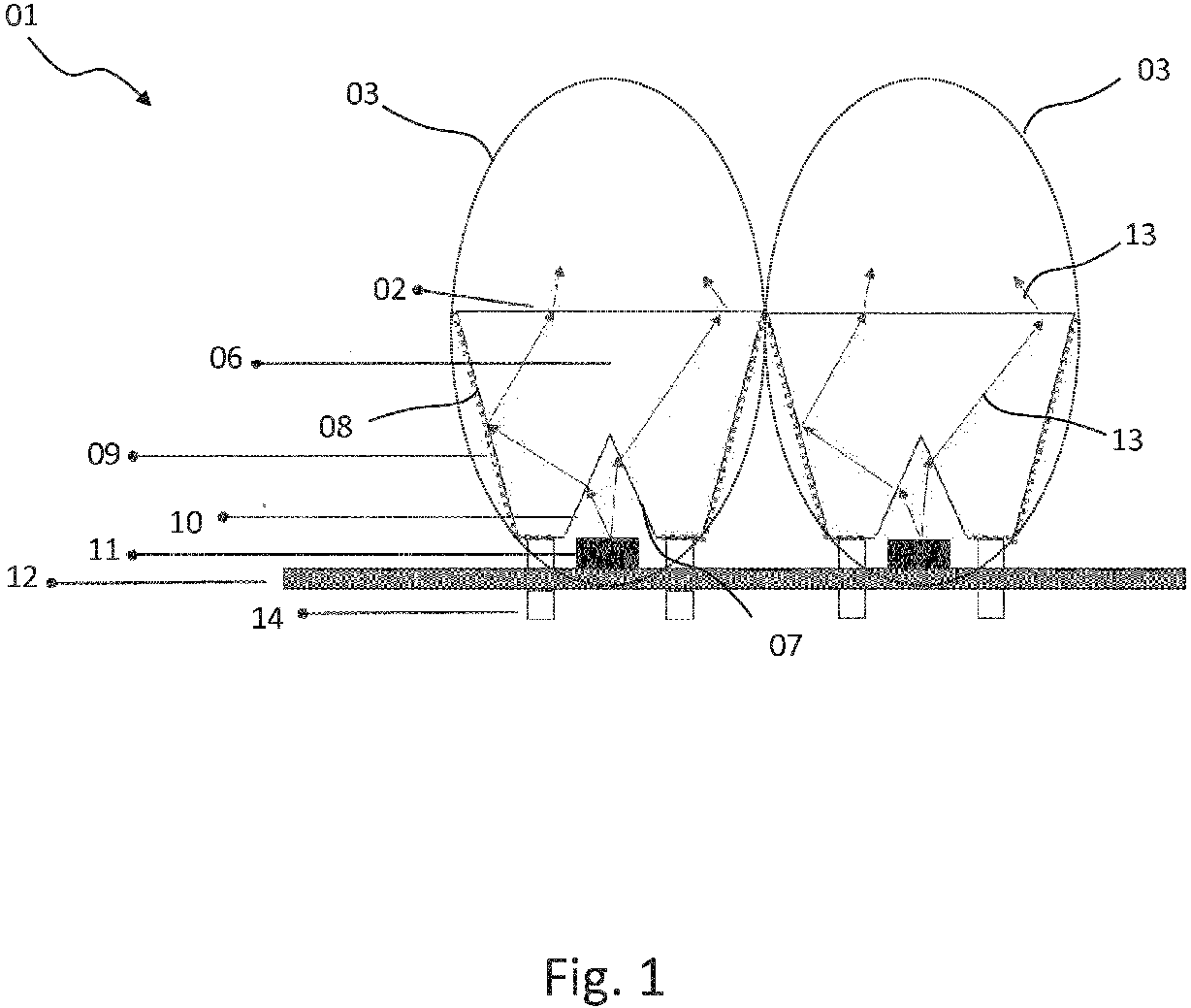
- Fig. 1
- ein Leuchtmittel mit einer durch Lichtaustrittsflächen der Optikkörper von Pixeln eines Pixelfelds gebildeten Leuchtfläche in einer einen eine auf der Leuchtfläche aufstehenden Flächennormale einschließenden Querschnitt durch zwei benachbarte Pixel hindurch zeigenden Ansicht.
- Fig. 2
- ein Ausführungsbeispiel einer durch ein Pixelfeld mit 21 quadratischen Pixeln mit einer Kantenlänge von 16 mm gebildeten Leuchtfläche eines Leuchtmittels in einer Draufsicht.
- Fig. 3
- ein Ausführungsbeispiel einer durch ein Pixelfeld mit 21 hexagonalen Pixeln mit einer Kantenlänge von 16 mm gebildeten Leuchtfläche eines Leuchtmittels in einer Draufsicht.
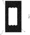
- Fig. 4
- ein erstes Ausführungsbeispiel einer Lichtsignatur einer durch das Pixelfeld aus
Fig. 3 verwirklichbaren Lichtfunktion in einer Draufsicht auf die Leuchtfläche, wobei bei dem Ausführungsbeispiel alle Pixel an sind und Licht abstrahlen. - Fig. 5
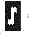
- ein zweites Ausführungsbeispiel einer Lichtsignatur einer durch das Pixelfeld aus
Fig. 3 verwirklichbaren Lichtfunktion in einer Draufsicht auf die Leuchtfläche, wobei bei dem Ausführungsbeispiel nur ein Teil der Pixel an sind und Licht abstrahlen. - Fig. 6
- ein drittes Ausführungsbeispiel einer Lichtsignatur einer durch das Pixelfeld aus
Fig. 3 verwirklichbaren Lichtfunktion in einer Draufsicht auf die Leuchtfläche, wobei bei dem Ausführungsbeispiel nur ein Teil der Pixel an sind und Licht abstrahlen. - Fig. 7
- ein viertes Ausführungsbeispiel einer Lichtsignatur einer durch das Pixelfeld aus
Fig. 3 verwirklichbaren Lichtfunktion in einer Draufsicht auf die Leuchtfläche, wobei bei dem Ausführungsbeispiel nur ein Teil der Pixel an sind und Licht abstrahlen. - Fig. 8
- ein fünftes Ausführungsbeispiel einer eine nach außerhalb einer Fahrzeugleuchte erkennbare Zusatzinformation "HI" beispielsweise für einen Betriebszustand eines Fahrzeugs, beispielsweise einen hohen Emissionszustand beispielsweise eines Hybridfahrzeugs oder einen hohen Ladezustand eines Stromspeichers eines Elektrofahrzeugs wiedergebenden, hierdurch funktionalen Lichtsignatur einer durch das Pixelfeld aus
Fig. 3 verwirklichbaren Lichtfunktion in einer Draufsicht auf die Leuchtfläche, wobei bei dem Ausführungsbeispiel nur ein Teil der Pixel an sind und Licht abstrahlen. - Fig. 9
- ein sechstes Ausführungsbeispiel einer eine nach außerhalb einer Fahrzeugleuchte erkennbare Zusatzinformation "LO" beispielsweise für einen Betriebszustand eines Fahrzeugs, beispielsweise einen niederen Emissionszustand beispielsweise eines Hybridfahrzeugs oder einen niederen Ladezustand eines Stromspeichers eines Elektrofahrzeugs wiedergebenden, hierdurch funktionalen Lichtsignatur einer durch das Pixelfeld aus
Fig. 3 verwirklichbaren Lichtfunktion in einer Draufsicht auf die Leuchtfläche, wobei bei dem Ausführungsbeispiel nur ein Teil der Pixel an sind und Licht abstrahlen. - Fig. 10
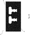
- ein siebtes Ausführungsbeispiel einer eine nach außerhalb einer Fahrzeugleuchte erkennbare Zusatzinformation "TT" beispielsweise für einen Betriebs- oder Wartungszustand eines Fahrzeugs wiedergebenden, hierdurch funktionalen Lichtsignatur einer durch das Pixelfeld aus
Fig. 3 verwirklichbaren Lichtfunktion in einer Draufsicht auf die Leuchtfläche, wobei bei dem Ausführungsbeispiel nur ein Teil der Pixel an sind und Licht abstrahlen. - Eine in
Fig. 1 ,Fig. 2 ,Fig. 3 ,Fig. 4 ,Fig. 5 ,Fig. 6 ,Fig. 7 ,Fig. 8 ,Fig. 9 ,Fig. 10 ganz oder in Teilen dargestelltes Leuchtmittel 01 umfasst eine durch Lichtaustrittsflächen 02 von Optikkörpern 06 von inFig. 1 jeweils durch ein es umgebendes, gestrichelt gezeichnetes Oval hervorgehobenen Pixeln 03 eines Pixelfelds 04 gebildete Leuchtfläche 05. - Jedes Pixel 03 des in
Fig. 2 ,Fig. 3 ,Fig. 4 ,Fig. 5 ,Fig. 6 ,Fig. 7 ,Fig. 8 ,Fig. 9 ,Fig. 10 durch ein es umgebendes, gestrichelt gezeichnetes Rechteck hervorgehobenes Pixelfelds 04 umfasst einen Optikkörper 06 mit einer vorderseitigen Lichtaustrittsfläche 02 und einer rückseitigen beispielsweise eine Primäroptik 10 umfassende Lichteinkoppelfläche 07 sowie eine jeweils um die Lichteinkoppelfläche 07 und um die Lichtaustrittsfläche 02 umlaufende, die Lichteinkoppelfläche 07 und die Lichtaustrittsfläche 02 miteinander verbindende Seitenfläche 08. - Zumindest die Seitenfläche 08 eines jeden Optikkörpers 06 und damit die Seitenfläche 08 des Optikkörpers 06 jeden Pixels 03 ist beispielsweise mittels einer durch einen Metallisierungs- und/oder Bedampfungsprozess hergestellten Verspiegelung 09 verspiegelt, um ein Überkoppeln von Licht aus einem Pixel 03 in ein benachbartes zu vermeiden.
- Der Lichteinkoppelfläche 07 des Optikkörpers 06 jeden Pixels 03 ist mindestens eine individuell ansteuerbare LED 11 als Lichtquelle zugeordnet, so dass jedes Pixel 03 des Pixelfelds 04 unabhängig von einem im Pixelfeld 04 benachbarten Pixel 03 ausleuchtbar ist.
- Die Lichtaustrittsflächen 02 der Optikkörper 06 bilden gemeinsam die Leuchtfläche 05 des Leuchtmittels 01.
- Das in
Fig. 1 von einer LED 11 emittierende Licht wird wie inFig. 1 durch Pfeile 13 dargestellt über die Primäroptik 10 des Optikkörpers 06 auf die Seitenfläche 08 des Optikkörpers 06 gelenkt. Von dort aus wird das Licht durch Total- und Reflexionseffekte zur kurz auch als Auskoppelfläche bezeichneten Lichtaustrittsfläche 02 gelenkt. Zum Teil wird Licht auch direkt von der Primäroptik 10 zur die Lichtaustrittsfläche 02 bildenden Auskoppeloberfläche gelenkt. Die Form der Lichtaustrittsfläche 02 kann dabei quadratisch, hexagonal, rund, oder auch Trapezförmig ausgeführt werden. Durch das diffuse, volumenstreuende Material erfährt das Licht auf jeden Fall weitere Streueffekte die in Summe zu einem homogenen Erscheinungsbild an der Lichtaustrittsfläche 02 und damit auch innerhalb der Leuchtfläche 05 führen. - Die an den Seitenflächen 08 und zum Teil an den Lichteinkoppelflächen 07 der Optikkörper 06 angebrachten, jeweils Verspiegelungen 09 bildenden Metallisierungsschicht verhindert ungewollten Lichtübertritt zum Nachbarelement. Die Schicht wird dabei durch ein Standardmetalisierungsverfahren aufgebracht. Die nichtbedampften Bereiche werden dabei durch Schablonen abgedeckt.
- Da das Streuverhalten des volumenstreuenden Materials in der Intensität anpassbar ist, ist der Optikkörper in der Größe beispielsweise zwischen 3 mm und 20 mm Kantenlänge, insbesondere zwischen 5 mm und 20 mm Kantenlänge, skalierbar.
- Bei den LEDs 11 des Leuchtmittels 01 kann es sich beispielsweise um LEDs zur Durchsteckmontage (THT; Through Hole Technology), oberflächenmontierbare (SMD; Surface Mounted Device) LEDs und LEDs handeln, bei denen der LED-Chip in Nacktmontagetechnik (COB; Chip On Board) direkt auf einen Leuchtmittelträger 12 gebondet wird.
- Das Leuchtmittel 01 kann darüber hinaus den Leuchtmittelträger 12 umfassen, der vorteilhaft als Leiterbahnträger zur elektrischen Kontaktierung wenigstens der LEDs 11 ausgeführt sein kann.
- Bei den in Verbindung mit einem Leuchtmittelträger 12 zum Einsatz kommenden Leiterbahnträgern handelt es sich um Leiterbahnträger, wie sie auch zur elektrischen Verschaltung von Elektronikbauteilen beispielsweise zur Ansteuerung von Leuchtmitteln mit anderen Lichtquellen als LEDs verwendet werden.
- Weit verbreitetste Leiterbahnträger sind kurz als Leiterkarte, Platine oder gedruckte Schaltung (printed circuit board, PCB) bezeichnete, starre Leiterplatten.
- Eine Leiterplatte ist ein Träger für elektronische Bauteile. Sie dient der mechanischen Befestigung und elektrischen Verbindung. Nahezu jedes elektronische Gerät enthält eine oder mehrere Leiterplatten.
- Eine weitere Möglichkeit zur mechanischen Befestigung und elektrischen Verbindung elektronischer Bauteile stellen in MID-Technik (MID-Technik: Molded-Interconnect-Device-Technik) hergestellte spritzgegossene Schaltungsträger dar. Hierbei werden mit den elektrischen Anschlüssen eines elektronischen Bauteils beispielsweise durch Oberflächenmontagetechnik, Durchsteckmontagetechnik oder durch Draht- oder ACF-Bonding zu kontaktierende Leiterbahnen in ein Spritzgussteil, welches gleichzeitig als Träger des einen oder der mehreren elektronischen Bauteile dient, im Spritzgussprozess integriert.
- Zum Betrieb von LEDs 11 als Lichtquellen für ein Leuchtmittel 01 beispielsweise einer Fahrzeugleuchte können eine oder mehrere mehr oder minder komplexe elektronische Steuerschaltungen vorgesehen sein, die beispielsweise auf einem oder mehreren Leuchtmittelträgern des Leuchtmittels angeordnet und in dem Leuchteninnenraum beherbergt sein können.
- Beispiele hierfür sind elektronische Steuerschaltungen:
- zur Regelung und/oder Steuerung der Helligkeit bzw. Leuchtkraft der LEDs, beispielsweise durch eine pulsweitenmodulierte Taktung der Stromversorgung für einen außerhalb des für das menschliche Auge wahrnehmbaren Bereichs gepulsten Betrieb,
- zur Kompensation oder Vermeidung elektromagnetischer Störungen, beispielsweise aufgebaut aus Kondensatoren und/oder Ferriten,
- zum Schutz der LEDs 11 z.B. vor einer Überspannung des Bordnetzes oder vor fehlerhafter Polung, beispielsweise umfassend eine oder mehrere Zenerdioden.
- Zusammengefasst muss für fast alle LED-Anwendungen eine mehr oder minder umfangreiche, für die speziellen LEDs 11 ausgelegte elektronische Steuerschaltung z.B. auf den mindestens einen Leuchtmittelträger 12 aufgebracht werden. Die elektronische Steuerschaltung umfasst im einfachsten Fall einen Vorwiderstand und eine Schutzdiode, kann aber je nach Anwendung auch wesentlich mehr Elektronikbauteile enthalten, wie z.B. Mikrokontroller bzw. Kontroller, Komparatoren, Transistoren, Schutzdioden, elektrische Widerstände z.B. als Vorwiderstand, Kondensatoren, Ferrite, etc.
- Somit kann ein Leuchtmittel 01 mit mehreren LEDs 11 als Lichtquellen zusätzlich zu einer oder mehreren aufgrund ihres Diodenaufbaus Elektronikbauteile darstellenden LEDs 11 zumindest ein weiteres zuvor genanntes Elektronikbauteil umfassen. Demnach kann ein Leuchtmittel 01 mit mehreren LEDs 11 als Lichtquellen neben den LEDs 11 zumindest noch über ein weiteres Elektronikbauteil verfügen.
- Die LEDs 11 und wenigstens ein weiteres Elektronikbauteil können auf einem gemeinsamen, einen Leiterbahnträger darstellenden Leuchtmittelträger 12, oder auf räumlich getrennten, untereinander beispielsweise durch einen Kabelbaum oder einen oder mehrere Teile eines Kabelbaums elektrisch verbundenen Leiterbahnträgern, von denen wenigstens einer den Leuchtmittelträger 12 bildet, angeordnet sein.
- Der Leuchtmittelträger 12 kann ferner mit Befestigungspins 14 zur Anordnung des Leuchtmittelträgers 12 und mit diesem des gesamten Leuchtmittels 01 ganz oder teilweise in einem Leuchteninnenraum beispielsweise einer Fahrzeugleuchte versehen sein.
- Die in einer Draufsicht auf das Pixelfeld 04 die einzelnen Pixel 03 bildenden Lichtaustrittsflächen 02 der Optikkörper 06 weisen in der Draufsicht bevorzugt eine maximale Abmessung, beispielsweise bei einer in der Draufsicht rechteckigen, insbesondere quadratischen Geometrie eine Kantenlänge, oder beispielsweise bei einer in der Draufsicht eher runden, insbesondere kreisrunden, oder mehreckigen, insbesondere hexagonalen Geometrie einen Durchmesser, von 3 mm bis 20 mm, besonders bevorzugt von 5 mm bis 16 mm, auf.
- Die Pixel 03 können in einer Draufsicht auf die durch die Lichtaustrittsflächen 02 der Optikkörper 06 der Pixel 03 gebildete Leuchtfläche 05 orthogonal zueinander, oder genestet angeordnet sein.
- Ein Beispiel einer orthogonalen Anordnung ist in
Fig. 2 dargestellt. Dabei verlaufen die Zeilen und Spalten in jeder Zeile und in jeder Spalte orthogonal zueinander. - Das in
Fig. 3 dargestellte Pixelfeld 04 weist eine ebenfalls orthogonale Anordnung seiner in insgesamt drei Zeilen und sieben Spalten angeordneten Pixel 03 auf, wobei diese innerhalb der Zeilen abwechselnd konvex-konkav ineinander übergehen. Innerhalb der Spalten liegen sie plan aneinander. Demnach umfasst das Pixelfeld 04 inFig. 3 eine Kombination aus mehreckiger Geometrie, sowie orthogonaler und genesteter Anordnung der Pixel 03. - Die einzelnen Pixel 03 können in der Draufsicht auf die durch das Pixelfeld 04 gebildete Leuchtfläche 05 eine rechteckige, insbesondere quadratische Geometrie aufweisen und/oder sechseckig, insbesondere hexagonal, und/oder rund ausgeführt sein. Alternativ oder zusätzlich können sie zeilen- beziehungsweise reihenweise und/oder spaltenweise konvex-konkav ineinander übergehen. Ferner sind beispielsweise konvex-konkav ineinander übergehende Kombinationen verschiedener Geometrien der Lichtaustrittsflächen 02 der Optikkörper 06 der Pixel 03 innerhalb des Pixelfelds 04 denkbar, wie dies durch die Kombination in
Fig. 3 bereits angedeutet ist. - Vorzugsweise bestehen die Optikkörper 06 zumindest zum Teil aus einem volumenstreuenden Material, um ein besonders homogenes Erscheinungsbild der Leuchtfläche 05 zu gewährleisten.
- Besonders vorteilhaft grenzen die Lichtaustrittsflächen 02 der Optikkörper 06 benachbarter Pixel 03 unmittelbar aneinander an.
- Ein zuvor beschriebenes Leuchtmittel 01 kann in einem von einem Leuchtengehäuse und einer zumindest für im für das menschliche Auge sichtbaren Teil des elektromagnetischen Spektrums liegendes Licht transparenten Lichtscheibe zumindest teilweise umschlossenen Leuchteninnenraum einer Fahrzeugleuchte beherbergt sein.
- Die Leuchtfläche 05 des Leuchtmittels 01 ist dabei beim Blick von außerhalb des Leuchteninnenraums durch die Lichtscheibe hindurch sichtbar.
- Das Leuchtengehäuse bzw. der Leuchteninnenraum kann in mehrere Kammern mit jeweils eigenen Lichtquellen und/oder Leuchtmitteln und/oder der Lichtverteilung dienenden und/oder beitragenden optischen Elementen sowie gegebenenfalls Lichtscheiben unterteilt sein, von denen mehrere Kammern gleiche und/oder jede Kammer eine andere Lichtfunktionen erfüllen kann.
- Die Fahrzeugleuchte kann einzelne oder eine Kombination der zuvor und/oder noch nachfolgend in Verbindung mit dem Leuchtmittel 01 beschriebene Merkmale aufweisen, ebenso wie das Leuchtmittel 01 einzelne oder eine Kombination mehrerer zuvor und/oder noch nachfolgend in Verbindung mit der Fahrzeugleuchte beschriebene Merkmale aufweisen und/oder verwirklichen kann.
- Die Fahrzeugleuchte und/oder das Leuchtmittel 01 können alternativ oder zusätzlich einzelne oder eine Kombination mehrerer einleitend in Verbindung mit dem Stand der Technik und/oder in einem oder mehreren der zum Stand der Technik erwähnten Dokumente und/oder in der voranstehenden oder noch nachfolgenden Beschreibung zu den in den Zeichnungen dargestellten Ausführungsbeispielen beschriebene Merkmale aufweisen.
- Wichtig ist hervorzuheben, dass die Erfindung verwirklicht sein kann durch ein Pixelfeld 04 aus makroskopischen Pixeln 03, von denen jedes durch einen Optikkörper 06 gebildet ist, der einer LED 11 vorgesetzt ist. Die Seitenflächen 08 sowie gegebenenfalls weitere Teilflächen der Optikkörper 06 sind mit einer Verspiegelung 09 versehen, um ein Übersprechen zwischen benachbarten Pixeln 03 zu vermeiden.
- Die Erfindung umfasst demnach eine Leuchtfläche 05 eines zur Erfüllung einer oder mehrerer Lichtfunktionen einer Fahrzeugleuchte vorgesehenen oder zumindest beitragenden Leuchtmittels 01, die aus den kurz als Auskoppelflächen bezeichneten Lichtaustrittsflächen 02 der Optikkörper 06 eines Felds und/oder einer Vielzahl skalierbarer makroskopischer Pixel 03 mit durch die Verspiegelung 09 zumindest der Seitenflächen 08 der Optikkörper 06 der einzelnen Pixel 03 des Pixelfelds 04 erzeugter, integrierter Lichtabschottung gebildet ist.
- Die Optikkörper 06 der Pixel 03 des Pixelfelds 04 sind hierbei makroskopisch mit maximalen Abmessungen ihrer jeweiligen Lichtaustrittsfläche 02 in der Draufsicht auf das Pixelfeld 04 von vorzugsweise 3 mm bis 20 mm, besonders bevorzugt zwischen 5 mm und 16 mm ausgeführt. Bei der Maximalen Abmessung kann es sich beispielsweise um eine Kantenlänge der Lichtaustrittsfläche 02 eines Optikkörpers 06 eines Pixels 03 handeln.
- Die Pixel 03 des Pixelfelds 04 sind außerdem skalierbar in ihren maximalen Abmessungen der Lichtaustrittsflächen 02 ihrer Optikkörper 06 in der Draufsicht auf das Pixelfeld 04 gesehen.
- Die Pixel 03 der Pixelfelds 04 sind ferner mit einer Lichtabschottung zum Nachbarpixel mit einer Dickenabmessung im Nanometerbereich versehen. Dies kann beispielsweise vermittels einer durch Metallisierung und/oder Bedampfung hergestellte Verspiegelung 09 der Seitenflächen 09 der Optikkörper 06 der Pixel 03 des Pixelfelds 04 verwirklicht sein.
- Ein jedes nachfolgend auch Optikkörper oder Optikelement genanntes Pixel 03 wird dabei durch eine konventionelle LED 11 als Lichtquelle betrieben. Dies ermöglicht je nach gewählter Lichtemissionsleistung der verwendeten LEDs 11 nicht nur die Verwirklichung von Schlusslichtfunktionen, sondern auch die Verwirklichung lichtintensiverer Lichtfunktionen wie beispielsweise einer Bremslichtfunktion und/oder einer beispielsweise durch eine Wiederholblinklichtfunktion gebildeten Fahrtrichtungsanzeige.
- Ein über die um mehrere Größenordnungen stärkere Lichtabstrahlung hinausgehender Vorteil gegenüber dem Stand der Technik ist dabei die quasi nicht sichtbare Lichtabschottung zwischen den Pixeln 03. Dies ermöglicht sowohl homogen leuchtende Flächenbereiche mit mehreren aktiven Pixeln 03 als auch scharf abgegrenzte, geometrische Formen zu nicht aktiven Pixeln 03, wie dies in
Fig. 5 ,Fig. 6 ,Fig. 7 ,Fig. 8 ,Fig. 9 ,Fig. 10 im Vergleich zu einem inFig. 4 dargestellten Zustand, in dem alle Pixel 03 eines Pixelfelds 04 Licht abstrahlen, dargestellt ist. Dies führt zu einem präzisen und hochwertigen und gut erkenn- und/oder lesbaren Erscheinungsbild, da ein ungewolltes Glimmen oder Mitleuchten von Nachbarpixeln vermieden wird. - Dadurch, dass für das Pixelfeld 04 nur Standardmaterialien, wie etwa volumenstreuender Kunststoff für die bevorzugt in Spritzgusstechnik hergestellten Optikkörper 06, standard Lichtquellen, wie etwa LEDs, 11 und Standardprozesse, wie etwa einer Metallisierung von Kunststoffoberflächen zur Erzeugung der Lichtabschottung zwischen den Nachbarpixeln, verwendet werden, wird eine kostengünstige Umsetzung erhalten.
- Zusätzliche, über die vollständige Lösung der gestellten Aufgabe und/oder über die voran zu den einzelnen Merkmalen genannten Vorteile hinausgehende Vorteile gegenüber dem Stand der Technik sind ebenfalls nachfolgend aufgeführt.
- Skalierbarkeit: Kleinere Kantenlänge erhöhen die Auflösung, insbesondere für Anwendungsfälle wie etwa Hinweissymbole, Buchstaben, Schriftzüge, anmierbare Logos (
Fig. 4 ,Fig. 5 ,Fig. 6 ,Fig. 7 ,Fig. 8 .Fig. 9 ,Fig. 10 ). Größere Kantenlänge verringern die Ansteuerungskosten, insbesondere für Anwendungsfälle mit mehreren Funktions-Signaturen (Fig. 8 ,Fig. 9 ,Fig. 10 ). Auch die Anzahl der Pixel 03 des Pixelfelds 04 ist skalierbar und nur Abhängig vom verfügbaren Bauraum und der Ansteuerung. - Homogenität: Durch die Verwendung von diffusem und volumenstreuendem Material ist eine gute Homogenität der lichtabstrahlenden Lichtaustrittsflächen und damit der gesamten Leuchtfläche 05 erzielbar. Da dieses Material auch oft als Streuscheibe bei bestehenden Funktionskonzepten Verwendung findet, ist ein kombinierter Einsatz möglich, ohne dass signifikante Unterschiede im Erscheinungsbild auftreten.
- Bi-Funktion: Durch Verwendung von Leistungsstärkeren LEDs können alle Pixel 03 des Pixelfelds oder auch nur Teilbereiche davon zur Verwirklichung einer Bremslichtfunktion oder beispielsweise einer Wiederholblinklichtfunktion zur Fahrtrichtungsanzeige betrieben werden. Auch der Betrieb mit Multi-Color LEDs ist möglich, so dass zum Beispiel Schlusslichtfunktion-Fahrtrichtungsanzeige Kombinationen mit roter und gelber Lichtfarbe für die verschiedenen Lichtfunktionen umsetzbar sind.
- Im Vergleich zu Display- und OLED-Lösungen setzt die Erfindung auf bewährte Materialien und Prozesse.
- Das Leuchtmittel 01 und einer hiermit ausgestattete Fahrzeugleuchte können alternativ oder zusätzlich zur Erfüllung einer oder mehrerer Lichtfunktionen von außerhalb der Fahrzeugleuchte erkennbare Zusatzinformationen bereitstellen, wie beispielsweise in
Fig. 8 ,Fig. 9 ,Fig. 10 gezeigt. - Aktuell wird im Zuge der Umweltdiskussionen - wie etwa über Feinstaub - auch verstärkt über die Kennbarmachung der unterschiedlichen Antriebssysteme wie z.B. Diesel, Benzin, Wasserstoff, Gas, Elektro, etc. gesprochen.
- Dies kann beispielsweise durch spezielle, von außerhalb der Fahrzeugleuchte erkennbare Zusatzinformationen kommuniziert werden. So kann beispielsweise eine Lichtsignatur wie in
Fig. 9 verwendet werden, um einen besonders emissionsarmen Betrieb (LO wie LOW EMISSION) von außerhalb kenntlich zu machen. Im Gegenzug kann auch der Betrieb eines Verbrennungsmotors mit fossilen Brennstoffen durch eine inFig. 8 gezeigte Lichtsignatur (HI wie HIGH EMISSION) nach außerhalb angezeigt werden. - Davon abgesehen, wollen die Nutzer beispielsweise von Elektrofahrzeugen ihr Umweltbewusstsein auch gerne nach außen tragen, im Sinne von "Ich mache was für die Umwelt!".
- Alternativ können solche Lichtsignaturen auch dazu benutzt werden, einem Nutzer beispielsweise eines Elektrofahrzeugs bevor dieser in das Elektrofahrzeug einsteigt, und/oder wenn dieser wieder aus dem Elektrofahrzeug ausgestiegen ist, den aktuellen Ladezustand (
Fig. 8 : HI wie HIGH;Fig. 9 : LO wie LOW) seines Stromspeichers anzuzeigen. - Ferner sind weitere Lichtsignaturen, wie etwa die in
Fig. 5 ,Fig. 6 ,Fig. 7 ,Fig. 10 dargestellten Lichtsignaturen denkbar, mit denen Benutzer von Fahrzeugen deren Erscheinung beispielsweise bei Annäherung an das Fahrzeug individualisieren können. - Die Erfindung ist nicht durch die Beschreibung anhand der Ausführungsbeispiele beschränkt. Vielmehr umfasst die Erfindung jedes neue Merkmal sowie jede Kombination von Merkmalen, was insbesondere jede Kombination von Merkmalen in den Ansprüchen beinhaltet, auch wenn dieses Merkmal oder diese Kombination selbst nicht explizit in den Ansprüchen oder Ausführungsbeispielen angegeben ist.
- Die Erfindung ist insbesondere im Bereich der Herstellung von Fahrzeugleuchten, insbesondere Kraftfahrzeugleuchten gewerblich anwendbar.
- Die Erfindung wurde unter Bezugnahme auf bevorzugte Ausführungsformen beschrieben. Es ist jedoch für einen Fachmann vorstellbar, dass Abwandlungen oder Änderungen der Erfindung gemacht werden können, ohne dabei den Schutzbereich der nachstehenden Ansprüche zu verlassen.
-
- 01
- Leuchtmittel
- 02
- Lichtaustrittsfläche
- 03
- Pixel
- 04
- Pixelfeld
- 05
- Leuchtfläche
- 06
- Optikkörper
- 07
- Lichteinkoppelfläche
- 08
- Seitenfläche
- 09
- Verspiegelung
- 10
- Primäroptik
- 11
- LED
- 12
- Leuchtmittelträger
- 13
- Pfeil
- 14
- Befestigungspin
Claims (7)
- Leuchtmittel (01) mit einer durch ein Pixelfeld (04) gebildeten Leuchtfläche (05), wobei:- jedes Pixel (03) des Pixelfelds (04) einen Optikkörper (06) mit einer vorderseitigen Lichtaustrittsfläche (02) und einer rückseitigen Lichteinkoppelfläche (07) sowie einer die Lichteinkoppelfläche (07) und die Lichtaustrittsfläche (02) miteinander verbindenden Seitenfläche (08) umfasst,- zumindest die Seitenfläche (08) des Optikkörpers (06) jeden Pixels (03) verspiegelt ist, und- der Lichteinkoppelfläche (02) des Optikkörpers jeden Pixels mindestens eine individuell ansteuerbare LED (11) als Lichtquelle zugeordnet ist.
- Fahrzeugleuchte mit einem von einem Leuchtengehäuse und einer Lichtscheibe zumindest teilweise umschlossenen Leuchteninnenraum, der ein Leuchtmittel (01) nach Anspruch 1 beherbergt.
- Leuchtmittel (01) oder Fahrzeugleuchte nach Anspruch 1 oder 2, wobei die in einer Draufsicht auf das Pixelfeld (04) die einzelnen Pixel (03) bildenden Lichtaustrittsflächen (02) der Optikkörper (06) eine maximale Abmessung von 3 mm bis 20 mm, bevorzugt von 5 mm bis 16 mm, aufweisen.
- Leuchtmittel (01) oder Fahrzeugleuchte nach Anspruch 1, 2 oder 3, wobei die Pixel (03) in einer Draufsicht orthogonal zueinander, oder genestet angeordnet sind.
- Leuchtmittel (01) oder Fahrzeugleuchte nach einem der Ansprüche 1 bis 4, wobei die einzelnen Pixel (03) eine rechteckige, insbesondere quadratische Geometrie aufweisen und/oder sechseckig und/oder rund ausgeführt sind und/oder konvex-konkav ineinander übergehen.
- Leuchtmittel (01) oder Fahrzeugleuchte nach einem der voranstehenden Ansprüche, wobei die Optikkörper (06) zumindest zum Teil aus einem volumenstreuenden Material bestehen.
- Leuchtmittel (01) oder Fahrzeugleuchte nach einem der voranstehenden Ansprüche, wobei die Lichtaustrittsflächen (02) der Optikkörper (06) benachbarter Pixel (03) unmittelbar aneinander angrenzen.
Priority Applications (2)
| Application Number | Priority Date | Filing Date | Title |
|---|---|---|---|
| SI201930766T SI3733453T1 (sl) | 2019-05-02 | 2019-05-02 | Luč za vozilo s svetilnim sredstvom |
| EP19172364.2A EP3733453B1 (de) | 2019-05-02 | 2019-05-02 | Fahzeugleuchte mit einem leuchtmittel |
Applications Claiming Priority (1)
| Application Number | Priority Date | Filing Date | Title |
|---|---|---|---|
| EP19172364.2A EP3733453B1 (de) | 2019-05-02 | 2019-05-02 | Fahzeugleuchte mit einem leuchtmittel |
Publications (2)
| Publication Number | Publication Date |
|---|---|
| EP3733453A1 true EP3733453A1 (de) | 2020-11-04 |
| EP3733453B1 EP3733453B1 (de) | 2024-04-10 |
Family
ID=66379834
Family Applications (1)
| Application Number | Title | Priority Date | Filing Date |
|---|---|---|---|
| EP19172364.2A Active EP3733453B1 (de) | 2019-05-02 | 2019-05-02 | Fahzeugleuchte mit einem leuchtmittel |
Country Status (2)
| Country | Link |
|---|---|
| EP (1) | EP3733453B1 (de) |
| SI (1) | SI3733453T1 (de) |
Citations (9)
| Publication number | Priority date | Publication date | Assignee | Title |
|---|---|---|---|---|
| US4733335A (en) * | 1984-12-28 | 1988-03-22 | Koito Manufacturing Co., Ltd. | Vehicular lamp |
| JPH0968934A (ja) * | 1995-09-01 | 1997-03-11 | Nec Eng Ltd | 表示モジュール |
| US20100039830A1 (en) * | 2008-08-18 | 2010-02-18 | The Hong Kong Polytechnic University | LED automotive tail lamp set |
| US20100331929A1 (en) * | 2008-02-28 | 2010-12-30 | Koninklijke Philips Electronics N.V. | Apparatus for spreading light from multiple sources to eliminate visible boundaries therebetween, light therapy devices including such apparatus, and methods |
| DE102011012297A1 (de) * | 2011-02-24 | 2012-08-30 | Osram Opto Semiconductors Gmbh | Beleuchtungsvorrichtung |
| EP2503222A1 (de) | 2011-03-15 | 2012-09-26 | Odelo GmbH | Kraftfahrzeugleuchte und Verfahren zu deren Betrieb |
| CN105179962A (zh) * | 2015-08-10 | 2015-12-23 | 广州市多普光电科技有限公司 | 一种柱状多面体矩阵led光源 |
| GB2554103A (en) * | 2016-09-20 | 2018-03-28 | Truck Lite Europe Ltd | Vehicle lamp |
| DE102018208822A1 (de) * | 2017-06-08 | 2018-12-13 | Seat, S.A. | Leuchtvorrichtung für ein Fahrzeug und zugehörige Heckklappe |
Family Cites Families (1)
| Publication number | Priority date | Publication date | Assignee | Title |
|---|---|---|---|---|
| DE102007033438B4 (de) * | 2007-07-18 | 2012-08-09 | Automotive Lighting Reutlingen Gmbh | Leuchte für Kraftfahrzeuge |
-
2019
- 2019-05-02 EP EP19172364.2A patent/EP3733453B1/de active Active
- 2019-05-02 SI SI201930766T patent/SI3733453T1/sl unknown
Patent Citations (9)
| Publication number | Priority date | Publication date | Assignee | Title |
|---|---|---|---|---|
| US4733335A (en) * | 1984-12-28 | 1988-03-22 | Koito Manufacturing Co., Ltd. | Vehicular lamp |
| JPH0968934A (ja) * | 1995-09-01 | 1997-03-11 | Nec Eng Ltd | 表示モジュール |
| US20100331929A1 (en) * | 2008-02-28 | 2010-12-30 | Koninklijke Philips Electronics N.V. | Apparatus for spreading light from multiple sources to eliminate visible boundaries therebetween, light therapy devices including such apparatus, and methods |
| US20100039830A1 (en) * | 2008-08-18 | 2010-02-18 | The Hong Kong Polytechnic University | LED automotive tail lamp set |
| DE102011012297A1 (de) * | 2011-02-24 | 2012-08-30 | Osram Opto Semiconductors Gmbh | Beleuchtungsvorrichtung |
| EP2503222A1 (de) | 2011-03-15 | 2012-09-26 | Odelo GmbH | Kraftfahrzeugleuchte und Verfahren zu deren Betrieb |
| CN105179962A (zh) * | 2015-08-10 | 2015-12-23 | 广州市多普光电科技有限公司 | 一种柱状多面体矩阵led光源 |
| GB2554103A (en) * | 2016-09-20 | 2018-03-28 | Truck Lite Europe Ltd | Vehicle lamp |
| DE102018208822A1 (de) * | 2017-06-08 | 2018-12-13 | Seat, S.A. | Leuchtvorrichtung für ein Fahrzeug und zugehörige Heckklappe |
Also Published As
| Publication number | Publication date |
|---|---|
| SI3733453T1 (sl) | 2024-07-31 |
| EP3733453B1 (de) | 2024-04-10 |
Similar Documents
| Publication | Publication Date | Title |
|---|---|---|
| DE10025810B4 (de) | Leuchteneinheit, insbesondere für Außenrückblickspiegel von Fahrzeugen, vorzugsweise von Kraftfahrzeugen | |
| DE102013223717B4 (de) | Kraftfahrzeugbeleuchtungseinrichtung mit zwei oder mehr in die gleiche Richtung strahlenden und in Hauptlichtaustrittsrichtung aufeinanderfolgend angeordneten OLEDs | |
| WO2020114969A1 (de) | Emblemanordnung für ein kraftfahrzeug | |
| DE102021129672A1 (de) | Beleuchtungsvorrichtung für ein Kraftfahrzeug | |
| EP1523431B1 (de) | Leuchte für kraftfahrzeuge | |
| DE202015100207U1 (de) | Leuchtmittel und hiermit ausgestattete Fahrzeugleuchte | |
| DE102021122264A1 (de) | Beleuchtungsvorrichtung für ein Fahrzeug | |
| DE102013008192A1 (de) | Beleuchtungsvorrichtung, insbesondere für ein Kraftfahrzeug | |
| DE102013217848A1 (de) | Signalleuchte für ein Kraftfahrzeug | |
| DE102017214656A1 (de) | Scheinwerfer für ein Kraftfahrzeug sowie Verfahren zum Betreiben eines Scheinwerfers | |
| DE202014101538U1 (de) | Kraftfahrzeugleuchte | |
| WO2020104126A1 (de) | Leuchte für ein kraftfahrzeug | |
| DE202018106219U1 (de) | Optikelementeanordnung, Leuchtmittel umfassend eine solche Optikelementeanordnung, sowie mit einem entsprechenden Leuchtmittel ausgestattete Fahrzeugleuchte | |
| EP3788298B1 (de) | Kraftfahrzeugbeleuchtungsmodul | |
| DE102010032946A1 (de) | Kraftfahrzeug mit einem Innenraum, in dem eine Beleuchtungseinrichtung angeordnet ist | |
| DE202020000304U1 (de) | Fahrzeug-Karosseriebauteil | |
| DE102017127925B4 (de) | Leuchtvorrichtung, insbesondere eine Signalleuchte, für Kraftfahrzeuge | |
| EP3466756B1 (de) | Animierbarer kaskadenlichtleiter | |
| DE102022126896A1 (de) | Beleuchtungsvorrichtung für ein Kraftfahrzeug | |
| DE102013225798B4 (de) | Außenspiegelanordnung mit optischer Anzeige | |
| EP3733453B1 (de) | Fahzeugleuchte mit einem leuchtmittel | |
| DE102022134044A1 (de) | Beleuchtungsvorrichtung für ein Kraftfahrzeug | |
| EP2955063A1 (de) | Kraftfahrzeugleuchte | |
| EP3553371A1 (de) | Leuchtmittel für fahrzeugleuchten mit einem plattenförmigen lichtleiter und hiermit ausgestattete fahrzeugleuchte | |
| EP3677831A1 (de) | Fahrzeugleuchte und verfahren zur erzeugung einer mindestleuchtfläche bei einer lichtfunktion einer fahrzeugleuchte |
Legal Events
| Date | Code | Title | Description |
|---|---|---|---|
| PUAI | Public reference made under article 153(3) epc to a published international application that has entered the european phase |
Free format text: ORIGINAL CODE: 0009012 |
|
| STAA | Information on the status of an ep patent application or granted ep patent |
Free format text: STATUS: REQUEST FOR EXAMINATION WAS MADE |
|
| 17P | Request for examination filed |
Effective date: 20200130 |
|
| AK | Designated contracting states |
Kind code of ref document: A1 Designated state(s): AL AT BE BG CH CY CZ DE DK EE ES FI FR GB GR HR HU IE IS IT LI LT LU LV MC MK MT NL NO PL PT RO RS SE SI SK SM TR |
|
| AX | Request for extension of the european patent |
Extension state: BA ME |
|
| STAA | Information on the status of an ep patent application or granted ep patent |
Free format text: STATUS: EXAMINATION IS IN PROGRESS |
|
| 17Q | First examination report despatched |
Effective date: 20220620 |
|
| RIC1 | Information provided on ipc code assigned before grant |
Ipc: H01L 33/58 20100101ALI20231017BHEP Ipc: F21Y 105/10 20160101ALI20231017BHEP Ipc: G02B 19/00 20060101ALI20231017BHEP Ipc: F21V 8/00 20060101ALI20231017BHEP Ipc: H01L 25/075 20060101ALI20231017BHEP Ipc: F21S 43/40 20180101ALI20231017BHEP Ipc: G09F 9/33 20060101ALI20231017BHEP Ipc: G09F 21/04 20060101ALI20231017BHEP Ipc: G09F 9/30 20060101ALI20231017BHEP Ipc: B60Q 1/50 20060101ALI20231017BHEP Ipc: F21S 43/31 20180101ALI20231017BHEP Ipc: F21S 43/20 20180101ALI20231017BHEP Ipc: F21S 43/14 20180101ALI20231017BHEP Ipc: B60Q 1/26 20060101AFI20231017BHEP |
|
| GRAP | Despatch of communication of intention to grant a patent |
Free format text: ORIGINAL CODE: EPIDOSNIGR1 |
|
| STAA | Information on the status of an ep patent application or granted ep patent |
Free format text: STATUS: GRANT OF PATENT IS INTENDED |
|
| INTG | Intention to grant announced |
Effective date: 20231130 |
|
| GRAS | Grant fee paid |
Free format text: ORIGINAL CODE: EPIDOSNIGR3 |
|
| GRAA | (expected) grant |
Free format text: ORIGINAL CODE: 0009210 |
|
| STAA | Information on the status of an ep patent application or granted ep patent |
Free format text: STATUS: THE PATENT HAS BEEN GRANTED |
|
| AK | Designated contracting states |
Kind code of ref document: B1 Designated state(s): AL AT BE BG CH CY CZ DE DK EE ES FI FR GB GR HR HU IE IS IT LI LT LU LV MC MK MT NL NO PL PT RO RS SE SI SK SM TR |
|
| REG | Reference to a national code |
Ref country code: GB Ref legal event code: FG4D Free format text: NOT ENGLISH |
|
| REG | Reference to a national code |
Ref country code: CH Ref legal event code: EP |
|
| REG | Reference to a national code |
Ref country code: DE Ref legal event code: R096 Ref document number: 502019010999 Country of ref document: DE |
|
| REG | Reference to a national code |
Ref country code: IE Ref legal event code: FG4D Free format text: LANGUAGE OF EP DOCUMENT: GERMAN |
|
| REG | Reference to a national code |
Ref country code: LT Ref legal event code: MG9D |
|
| REG | Reference to a national code |
Ref country code: NL Ref legal event code: MP Effective date: 20240410 |
|
| PG25 | Lapsed in a contracting state [announced via postgrant information from national office to epo] |
Ref country code: NL Free format text: LAPSE BECAUSE OF FAILURE TO SUBMIT A TRANSLATION OF THE DESCRIPTION OR TO PAY THE FEE WITHIN THE PRESCRIBED TIME-LIMIT Effective date: 20240410 |
|
| PG25 | Lapsed in a contracting state [announced via postgrant information from national office to epo] |
Ref country code: NL Free format text: LAPSE BECAUSE OF FAILURE TO SUBMIT A TRANSLATION OF THE DESCRIPTION OR TO PAY THE FEE WITHIN THE PRESCRIBED TIME-LIMIT Effective date: 20240410 |
|
| PG25 | Lapsed in a contracting state [announced via postgrant information from national office to epo] |
Ref country code: IS Free format text: LAPSE BECAUSE OF FAILURE TO SUBMIT A TRANSLATION OF THE DESCRIPTION OR TO PAY THE FEE WITHIN THE PRESCRIBED TIME-LIMIT Effective date: 20240810 |
|
| PG25 | Lapsed in a contracting state [announced via postgrant information from national office to epo] |
Ref country code: BG Free format text: LAPSE BECAUSE OF FAILURE TO SUBMIT A TRANSLATION OF THE DESCRIPTION OR TO PAY THE FEE WITHIN THE PRESCRIBED TIME-LIMIT Effective date: 20240410 |
|
| PG25 | Lapsed in a contracting state [announced via postgrant information from national office to epo] |
Ref country code: FI Free format text: LAPSE BECAUSE OF FAILURE TO SUBMIT A TRANSLATION OF THE DESCRIPTION OR TO PAY THE FEE WITHIN THE PRESCRIBED TIME-LIMIT Effective date: 20240410 Ref country code: HR Free format text: LAPSE BECAUSE OF FAILURE TO SUBMIT A TRANSLATION OF THE DESCRIPTION OR TO PAY THE FEE WITHIN THE PRESCRIBED TIME-LIMIT Effective date: 20240410 |
|
| PG25 | Lapsed in a contracting state [announced via postgrant information from national office to epo] |
Ref country code: GR Free format text: LAPSE BECAUSE OF FAILURE TO SUBMIT A TRANSLATION OF THE DESCRIPTION OR TO PAY THE FEE WITHIN THE PRESCRIBED TIME-LIMIT Effective date: 20240711 |
|
| PG25 | Lapsed in a contracting state [announced via postgrant information from national office to epo] |
Ref country code: PT Free format text: LAPSE BECAUSE OF FAILURE TO SUBMIT A TRANSLATION OF THE DESCRIPTION OR TO PAY THE FEE WITHIN THE PRESCRIBED TIME-LIMIT Effective date: 20240812 |
|
| PG25 | Lapsed in a contracting state [announced via postgrant information from national office to epo] |
Ref country code: ES Free format text: LAPSE BECAUSE OF FAILURE TO SUBMIT A TRANSLATION OF THE DESCRIPTION OR TO PAY THE FEE WITHIN THE PRESCRIBED TIME-LIMIT Effective date: 20240410 |
|
| PG25 | Lapsed in a contracting state [announced via postgrant information from national office to epo] |
Ref country code: PL Free format text: LAPSE BECAUSE OF FAILURE TO SUBMIT A TRANSLATION OF THE DESCRIPTION OR TO PAY THE FEE WITHIN THE PRESCRIBED TIME-LIMIT Effective date: 20240410 |
|
| PG25 | Lapsed in a contracting state [announced via postgrant information from national office to epo] |
Ref country code: LV Free format text: LAPSE BECAUSE OF FAILURE TO SUBMIT A TRANSLATION OF THE DESCRIPTION OR TO PAY THE FEE WITHIN THE PRESCRIBED TIME-LIMIT Effective date: 20240410 |
|
| PG25 | Lapsed in a contracting state [announced via postgrant information from national office to epo] |
Ref country code: PT Free format text: LAPSE BECAUSE OF FAILURE TO SUBMIT A TRANSLATION OF THE DESCRIPTION OR TO PAY THE FEE WITHIN THE PRESCRIBED TIME-LIMIT Effective date: 20240812 Ref country code: PL Free format text: LAPSE BECAUSE OF FAILURE TO SUBMIT A TRANSLATION OF THE DESCRIPTION OR TO PAY THE FEE WITHIN THE PRESCRIBED TIME-LIMIT Effective date: 20240410 Ref country code: NO Free format text: LAPSE BECAUSE OF FAILURE TO SUBMIT A TRANSLATION OF THE DESCRIPTION OR TO PAY THE FEE WITHIN THE PRESCRIBED TIME-LIMIT Effective date: 20240710 Ref country code: LV Free format text: LAPSE BECAUSE OF FAILURE TO SUBMIT A TRANSLATION OF THE DESCRIPTION OR TO PAY THE FEE WITHIN THE PRESCRIBED TIME-LIMIT Effective date: 20240410 Ref country code: IS Free format text: LAPSE BECAUSE OF FAILURE TO SUBMIT A TRANSLATION OF THE DESCRIPTION OR TO PAY THE FEE WITHIN THE PRESCRIBED TIME-LIMIT Effective date: 20240810 Ref country code: HR Free format text: LAPSE BECAUSE OF FAILURE TO SUBMIT A TRANSLATION OF THE DESCRIPTION OR TO PAY THE FEE WITHIN THE PRESCRIBED TIME-LIMIT Effective date: 20240410 Ref country code: GR Free format text: LAPSE BECAUSE OF FAILURE TO SUBMIT A TRANSLATION OF THE DESCRIPTION OR TO PAY THE FEE WITHIN THE PRESCRIBED TIME-LIMIT Effective date: 20240711 Ref country code: FI Free format text: LAPSE BECAUSE OF FAILURE TO SUBMIT A TRANSLATION OF THE DESCRIPTION OR TO PAY THE FEE WITHIN THE PRESCRIBED TIME-LIMIT Effective date: 20240410 Ref country code: ES Free format text: LAPSE BECAUSE OF FAILURE TO SUBMIT A TRANSLATION OF THE DESCRIPTION OR TO PAY THE FEE WITHIN THE PRESCRIBED TIME-LIMIT Effective date: 20240410 Ref country code: BG Free format text: LAPSE BECAUSE OF FAILURE TO SUBMIT A TRANSLATION OF THE DESCRIPTION OR TO PAY THE FEE WITHIN THE PRESCRIBED TIME-LIMIT Effective date: 20240410 Ref country code: RS Free format text: LAPSE BECAUSE OF FAILURE TO SUBMIT A TRANSLATION OF THE DESCRIPTION OR TO PAY THE FEE WITHIN THE PRESCRIBED TIME-LIMIT Effective date: 20240710 |
|
| REG | Reference to a national code |
Ref country code: DE Ref legal event code: R082 Ref document number: 502019010999 Country of ref document: DE Representative=s name: BENNINGER, JOHANNES, DIPL.-ING., DE |
|
| REG | Reference to a national code |
Ref country code: CH Ref legal event code: PL |
|
| REG | Reference to a national code |
Ref country code: DE Ref legal event code: R097 Ref document number: 502019010999 Country of ref document: DE |
|
| PG25 | Lapsed in a contracting state [announced via postgrant information from national office to epo] |
Ref country code: DK Free format text: LAPSE BECAUSE OF FAILURE TO SUBMIT A TRANSLATION OF THE DESCRIPTION OR TO PAY THE FEE WITHIN THE PRESCRIBED TIME-LIMIT Effective date: 20240410 |
|
| PG25 | Lapsed in a contracting state [announced via postgrant information from national office to epo] |
Ref country code: LU Free format text: LAPSE BECAUSE OF NON-PAYMENT OF DUE FEES Effective date: 20240502 |
|
| PG25 | Lapsed in a contracting state [announced via postgrant information from national office to epo] |
Ref country code: EE Free format text: LAPSE BECAUSE OF FAILURE TO SUBMIT A TRANSLATION OF THE DESCRIPTION OR TO PAY THE FEE WITHIN THE PRESCRIBED TIME-LIMIT Effective date: 20240410 |
|
| PG25 | Lapsed in a contracting state [announced via postgrant information from national office to epo] |
Ref country code: CZ Free format text: LAPSE BECAUSE OF FAILURE TO SUBMIT A TRANSLATION OF THE DESCRIPTION OR TO PAY THE FEE WITHIN THE PRESCRIBED TIME-LIMIT Effective date: 20240410 |
|
| PG25 | Lapsed in a contracting state [announced via postgrant information from national office to epo] |
Ref country code: SK Free format text: LAPSE BECAUSE OF FAILURE TO SUBMIT A TRANSLATION OF THE DESCRIPTION OR TO PAY THE FEE WITHIN THE PRESCRIBED TIME-LIMIT Effective date: 20240410 Ref country code: RO Free format text: LAPSE BECAUSE OF FAILURE TO SUBMIT A TRANSLATION OF THE DESCRIPTION OR TO PAY THE FEE WITHIN THE PRESCRIBED TIME-LIMIT Effective date: 20240410 |
|
| PG25 | Lapsed in a contracting state [announced via postgrant information from national office to epo] |
Ref country code: SM Free format text: LAPSE BECAUSE OF FAILURE TO SUBMIT A TRANSLATION OF THE DESCRIPTION OR TO PAY THE FEE WITHIN THE PRESCRIBED TIME-LIMIT Effective date: 20240410 |
|
| PG25 | Lapsed in a contracting state [announced via postgrant information from national office to epo] |
Ref country code: SM Free format text: LAPSE BECAUSE OF FAILURE TO SUBMIT A TRANSLATION OF THE DESCRIPTION OR TO PAY THE FEE WITHIN THE PRESCRIBED TIME-LIMIT Effective date: 20240410 Ref country code: SK Free format text: LAPSE BECAUSE OF FAILURE TO SUBMIT A TRANSLATION OF THE DESCRIPTION OR TO PAY THE FEE WITHIN THE PRESCRIBED TIME-LIMIT Effective date: 20240410 Ref country code: RO Free format text: LAPSE BECAUSE OF FAILURE TO SUBMIT A TRANSLATION OF THE DESCRIPTION OR TO PAY THE FEE WITHIN THE PRESCRIBED TIME-LIMIT Effective date: 20240410 Ref country code: LU Free format text: LAPSE BECAUSE OF NON-PAYMENT OF DUE FEES Effective date: 20240502 Ref country code: EE Free format text: LAPSE BECAUSE OF FAILURE TO SUBMIT A TRANSLATION OF THE DESCRIPTION OR TO PAY THE FEE WITHIN THE PRESCRIBED TIME-LIMIT Effective date: 20240410 Ref country code: DK Free format text: LAPSE BECAUSE OF FAILURE TO SUBMIT A TRANSLATION OF THE DESCRIPTION OR TO PAY THE FEE WITHIN THE PRESCRIBED TIME-LIMIT Effective date: 20240410 Ref country code: CZ Free format text: LAPSE BECAUSE OF FAILURE TO SUBMIT A TRANSLATION OF THE DESCRIPTION OR TO PAY THE FEE WITHIN THE PRESCRIBED TIME-LIMIT Effective date: 20240410 Ref country code: CH Free format text: LAPSE BECAUSE OF NON-PAYMENT OF DUE FEES Effective date: 20240531 Ref country code: MC Free format text: LAPSE BECAUSE OF FAILURE TO SUBMIT A TRANSLATION OF THE DESCRIPTION OR TO PAY THE FEE WITHIN THE PRESCRIBED TIME-LIMIT Effective date: 20240410 |
|
| PLBE | No opposition filed within time limit |
Free format text: ORIGINAL CODE: 0009261 |
|
| STAA | Information on the status of an ep patent application or granted ep patent |
Free format text: STATUS: NO OPPOSITION FILED WITHIN TIME LIMIT |
|
| REG | Reference to a national code |
Ref country code: BE Ref legal event code: MM Effective date: 20240531 |
|
| 26N | No opposition filed |
Effective date: 20250113 |
|
| GBPC | Gb: european patent ceased through non-payment of renewal fee |
Effective date: 20240710 |
|
| PG25 | Lapsed in a contracting state [announced via postgrant information from national office to epo] |
Ref country code: IE Free format text: LAPSE BECAUSE OF NON-PAYMENT OF DUE FEES Effective date: 20240502 |
|
| PG25 | Lapsed in a contracting state [announced via postgrant information from national office to epo] |
Ref country code: BE Free format text: LAPSE BECAUSE OF NON-PAYMENT OF DUE FEES Effective date: 20240531 |
|
| PG25 | Lapsed in a contracting state [announced via postgrant information from national office to epo] |
Ref country code: GB Free format text: LAPSE BECAUSE OF NON-PAYMENT OF DUE FEES Effective date: 20240710 |
|
| PGFP | Annual fee paid to national office [announced via postgrant information from national office to epo] |
Ref country code: DE Payment date: 20250618 Year of fee payment: 7 |
|
| REG | Reference to a national code |
Ref country code: AT Ref legal event code: MM01 Ref document number: 1674618 Country of ref document: AT Kind code of ref document: T Effective date: 20240502 |
|
| PGFP | Annual fee paid to national office [announced via postgrant information from national office to epo] |
Ref country code: FR Payment date: 20250620 Year of fee payment: 7 |
|
| PG25 | Lapsed in a contracting state [announced via postgrant information from national office to epo] |
Ref country code: AT Free format text: LAPSE BECAUSE OF NON-PAYMENT OF DUE FEES Effective date: 20240502 |
|
| PGFP | Annual fee paid to national office [announced via postgrant information from national office to epo] |
Ref country code: SI Payment date: 20250605 Year of fee payment: 7 |
|
| PG25 | Lapsed in a contracting state [announced via postgrant information from national office to epo] |
Ref country code: CY Free format text: LAPSE BECAUSE OF FAILURE TO SUBMIT A TRANSLATION OF THE DESCRIPTION OR TO PAY THE FEE WITHIN THE PRESCRIBED TIME-LIMIT; INVALID AB INITIO Effective date: 20190502 |
|
| PG25 | Lapsed in a contracting state [announced via postgrant information from national office to epo] |
Ref country code: HU Free format text: LAPSE BECAUSE OF FAILURE TO SUBMIT A TRANSLATION OF THE DESCRIPTION OR TO PAY THE FEE WITHIN THE PRESCRIBED TIME-LIMIT; INVALID AB INITIO Effective date: 20190502 |
|
| PG25 | Lapsed in a contracting state [announced via postgrant information from national office to epo] |
Ref country code: SE Free format text: LAPSE BECAUSE OF FAILURE TO SUBMIT A TRANSLATION OF THE DESCRIPTION OR TO PAY THE FEE WITHIN THE PRESCRIBED TIME-LIMIT Effective date: 20240410 |
|
| PGFP | Annual fee paid to national office [announced via postgrant information from national office to epo] |
Ref country code: IT Payment date: 20250624 Year of fee payment: 7 |