EP3733293B1 - Vorrichtung für ein testinstrument für mehrere proben - Google Patents
Vorrichtung für ein testinstrument für mehrere proben Download PDFInfo
- Publication number
- EP3733293B1 EP3733293B1 EP20154237.0A EP20154237A EP3733293B1 EP 3733293 B1 EP3733293 B1 EP 3733293B1 EP 20154237 A EP20154237 A EP 20154237A EP 3733293 B1 EP3733293 B1 EP 3733293B1
- Authority
- EP
- European Patent Office
- Prior art keywords
- fixture
- specimen
- star
- msf
- cross
- Prior art date
- Legal status (The legal status is an assumption and is not a legal conclusion. Google has not performed a legal analysis and makes no representation as to the accuracy of the status listed.)
- Active
Links
Images




Classifications
-
- B—PERFORMING OPERATIONS; TRANSPORTING
- B01—PHYSICAL OR CHEMICAL PROCESSES OR APPARATUS IN GENERAL
- B01L—CHEMICAL OR PHYSICAL LABORATORY APPARATUS FOR GENERAL USE
- B01L7/00—Heating or cooling apparatus; Heat insulating devices
- B01L7/02—Water baths; Sand baths; Air baths
-
- G—PHYSICS
- G01—MEASURING; TESTING
- G01N—INVESTIGATING OR ANALYSING MATERIALS BY DETERMINING THEIR CHEMICAL OR PHYSICAL PROPERTIES
- G01N3/00—Investigating strength properties of solid materials by application of mechanical stress
- G01N3/02—Details
- G01N3/04—Chucks
-
- G—PHYSICS
- G01—MEASURING; TESTING
- G01N—INVESTIGATING OR ANALYSING MATERIALS BY DETERMINING THEIR CHEMICAL OR PHYSICAL PROPERTIES
- G01N3/00—Investigating strength properties of solid materials by application of mechanical stress
- G01N3/08—Investigating strength properties of solid materials by application of mechanical stress by applying steady tensile or compressive forces
-
- G—PHYSICS
- G05—CONTROLLING; REGULATING
- G05D—SYSTEMS FOR CONTROLLING OR REGULATING NON-ELECTRIC VARIABLES
- G05D9/00—Level control, e.g. controlling quantity of material stored in vessel
- G05D9/12—Level control, e.g. controlling quantity of material stored in vessel characterised by the use of electric means
-
- B—PERFORMING OPERATIONS; TRANSPORTING
- B01—PHYSICAL OR CHEMICAL PROCESSES OR APPARATUS IN GENERAL
- B01L—CHEMICAL OR PHYSICAL LABORATORY APPARATUS FOR GENERAL USE
- B01L2300/00—Additional constructional details
- B01L2300/06—Auxiliary integrated devices, integrated components
- B01L2300/0627—Sensor or part of a sensor is integrated
- B01L2300/0663—Whole sensors
-
- B—PERFORMING OPERATIONS; TRANSPORTING
- B01—PHYSICAL OR CHEMICAL PROCESSES OR APPARATUS IN GENERAL
- B01L—CHEMICAL OR PHYSICAL LABORATORY APPARATUS FOR GENERAL USE
- B01L2300/00—Additional constructional details
- B01L2300/08—Geometry, shape and general structure
- B01L2300/0861—Configuration of multiple channels and/or chambers in a single devices
-
- B—PERFORMING OPERATIONS; TRANSPORTING
- B01—PHYSICAL OR CHEMICAL PROCESSES OR APPARATUS IN GENERAL
- B01L—CHEMICAL OR PHYSICAL LABORATORY APPARATUS FOR GENERAL USE
- B01L2300/00—Additional constructional details
- B01L2300/18—Means for temperature control
-
- F—MECHANICAL ENGINEERING; LIGHTING; HEATING; WEAPONS; BLASTING
- F16—ENGINEERING ELEMENTS AND UNITS; GENERAL MEASURES FOR PRODUCING AND MAINTAINING EFFECTIVE FUNCTIONING OF MACHINES OR INSTALLATIONS; THERMAL INSULATION IN GENERAL
- F16K—VALVES; TAPS; COCKS; ACTUATING-FLOATS; DEVICES FOR VENTING OR AERATING
- F16K31/00—Actuating devices; Operating means; Releasing devices
- F16K31/12—Actuating devices; Operating means; Releasing devices actuated by fluid
- F16K31/18—Actuating devices; Operating means; Releasing devices actuated by fluid actuated by a float
-
- G—PHYSICS
- G01—MEASURING; TESTING
- G01N—INVESTIGATING OR ANALYSING MATERIALS BY DETERMINING THEIR CHEMICAL OR PHYSICAL PROPERTIES
- G01N2203/00—Investigating strength properties of solid materials by application of mechanical stress
- G01N2203/02—Details not specific for a particular testing method
- G01N2203/04—Chucks, fixtures, jaws, holders or anvils
-
- G—PHYSICS
- G01—MEASURING; TESTING
- G01N—INVESTIGATING OR ANALYSING MATERIALS BY DETERMINING THEIR CHEMICAL OR PHYSICAL PROPERTIES
- G01N2203/00—Investigating strength properties of solid materials by application of mechanical stress
- G01N2203/02—Details not specific for a particular testing method
- G01N2203/04—Chucks, fixtures, jaws, holders or anvils
- G01N2203/0464—Chucks, fixtures, jaws, holders or anvils with provisions for testing more than one specimen at the time
- G01N2203/0476—Chucks, fixtures, jaws, holders or anvils with provisions for testing more than one specimen at the time in parallel
Definitions
- the technology generally relates to test instruments for mechanical characterization and fatigue testing. More particularly, the technology relates to a multi-specimen test fixture star.
- test durations may extend from less than a day to several weeks or more.
- the liquid may evaporate during testing, consequently, test personnel may repeatedly add liquid to the bath to ensure the specimens remain immersed throughout the duration of the test.
- the temperature of the bath liquid and the temperature of the added liquid may be different. If the temperature difference is substantial and if the volume of added liquid is significant relative to the bath volume, the bath temperature can change significantly during liquid replenishment. As a result, the temperature of the specimens can change significantly. Additionally, the process of adding liquid to the bath introduces a risk of spillage and the movement of liquid in the bath resulting from adding the liquid may damage the specimens.
- the specimens may be held in a multi-specimen fixture (MSF).
- MSF multi-specimen fixture
- the MSF has a radially symmetric configuration.
- the radially symmetric configuration has uniform deformation at each specimen site under application of a load; however, increasing the size of the specimens and/or increasing the number of specimens results in a large increase in the fixture size. In some instances, the increase may be limited by the available space of the test system.
- one or more specimens may be visually obscured due to the circular MSF geometry and components of the test system.
- a user may want to test different lengths of specimens for different test procedures. Individual tests are configured for multiple specimens each at the same length. To change to specimens of a different length for a different test, significant time may be required (e.g., several hours or more) due to specimen alignment requirements and partial disassembly and reassembly of the test instrument.
- US2003/033896 discloses an automated sample tester.
- CN108072567 discloses a plastic constant-temperature stress corrosion experiment device and method.
- WO2017/202396 discloses a jig for mounting samples in a test device for material contact fatigue tests.
- the invention provides a multi-specimen test fixture star as claimed.
- a test chamber device which includes a bath chamber, a supply reservoir, a fluid channel, a liquid level sensor and a valve.
- the bath chamber is configured to receive one or more test specimens and to hold a first volume of a liquid.
- the supply reservoir holds a second volume of the liquid.
- the fluid channel fluidically couples the bath chamber and the supply reservoir.
- the liquid level sensor is disposed at one of the bath chamber and the supply reservoir and is configured to sense a liquid level.
- the valve is configured to fluidically couple a source of the liquid to the supply reservoir and is responsive to a sensed liquid level as determined by the liquid level sensor. The valve dispenses a volume of the liquid from the source of the liquid into the supply reservoir when the liquid level decreases to a threshold liquid level.
- the liquid level sensor and the valve may be a float valve.
- the liquid level sensor may include at least one of an optical sensor, an electro-mechanical switch and an electrical sensor.
- the liquid may be a saline solution.
- the valve may include at least one of a pneumatic actuator, a hydraulic actuator and an electrical actuator.
- the bath chamber may include a heating surface.
- the bath chamber may include a wall where one end of the fluid channel is disposed at the wall and is proximate to the heating surface.
- the supply reservoir may be disposed adjacent to the bath chamber and the fluid channel may include an opening through a wall separating the first volume of the liquid from the second volume of the liquid.
- the fluid channel may include a tube extending from the supply reservoir to the bath chamber.
- the fixture arms of a multi-specimen test fixture star embodying the invention may extend radially from an axial fixture opening at the fixture center and the multi-specimen text fixture star may further include a fixture hub configured for coupling the multi-specimen text fixture star to the shaft and disposed at the axial opening.
- a cross-section of each of the fixture arms may be configured to achieve a displacement at the specimen attachment location, resulting from the applied load, that is substantially equal to the displacement at each of the other specimen attachment locations.
- a cross-section of each of the cross-members may be configured to achieve a displacement at the specimen attachment location, resulting from the applied load, that is substantially equal to the displacement at each of the other specimen attachment locations.
- At least one of a width, a length and a thickness of at least one fixture arm may be different than at least one of the width, the length and the thickness of at least one other fixture arm.
- At least one of a width, a length and a thickness of at least one cross-member may be different than at least one of the width, the length and the thickness of at least one other cross-member.
- a width, a length and a thickness of each fixture arm is the same as the width, the length and the thickness of a diametrically-opposed fixture arm.
- a width, a length and a thickness of each cross-member is the same as the width, the length and the thickness of a diametrically-opposed cross-member.
- the rectangular shape may be a square shape.
- the specimen attachment locations may be first specimen attachment locations and the multi-specimen test fixture star may further include a plurality of second specimen attachment locations each disposed along a length of one of the fixture arms between the arm end and the fixture hub and the multi-specimen test fixture star is configured such that, in use, the load applied by the central shaft is equally distributed to the first and second specimen attachment locations.
- the second specimen attachment locations may define a rectangular array centered on the fixture center.
- a multi-specimen test fixture which includes a shaft, a multi-specimen test fixture star, a locking collar and a clamp.
- the shaft has a shaft axis and a cylindrical surface with a keyway formed in the cylindrical surface.
- the multi-specimen test fixture star has an axial fixture opening at a fixture center and has a plurality of fixture arms. Each fixture arm has an arm end and extending radially from the axial opening and each fixture arm has a specimen attachment location.
- the locking collar is in engagement with the multi-specimen test fixture star and has an axial collar opening to pass the shaft.
- the locking collar has a cylindrical inner surface that is parallel to the cylindrical surface of the shaft and the locking collar has a key member extending from the cylindrical inner surface into the keyway such that the multi-specimen test fixture star is prevented from rotating about the shaft axis.
- the clamp secures the locking collar to the shaft.
- the multi-specimen test fixture star is adjustable in position along a length of the shaft according to a position of the locking collar on the shaft and a load applied along the axis of the shaft is equally distributed to the specimen attachment locations.
- the locking collar and the clamp are formed as a unitary component.
- the keyway may include a slot having a length that is parallel to the shaft axis.
- the slot may have a rectangular cross-section or may be a V-shaped slot.
- the key member may include a spherical surface.
- the key member may be a spring-loaded member.
- examples disclosed herein are directed to a test device not forming part of the present invention, a multi-specimen test fixture star according to the appended set of claims and a multi-specimen test fixture not forming part of the present invention.
- the test device includes a bath chamber that is automatically replenished with bath liquid throughout an extended test period.
- the multi-specimen test fixture star is non-circularly symmetric and can be used, for example, in a rectangular bath chamber to hold a greater number of test specimens than a circularly symmetric test fixture star.
- the multi-specimen text fixture includes, in part, a multi-specimen text fixture star and a shaft having one or more keyways and allows the test fixture star to be repositioned along the shaft without loss of rotational alignment of the star to the shaft.
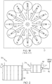
- FIG. 1A is a simplified block diagram depicting a cross-section of a dynamic mechanical test instrument 10 that can, for example, perform multi-specimen fatigue testing.
- the test instrument 10 may be used for conducting tension-tension, compression-compression or tension-compression tests to derive fatigue life curves and failure criteria for various devices and structure.
- specimens that can be tested include stents, heart valves and their components, leads for implantable devices, textiles, fabrics, fabric strands and wire.
- the test instrument 10 may provide tension or compression displacements of tens of millimeters and may cycle at rates up to a few hundred cycles per second.
- the test instrument 10 includes an open-top box structure 12 which holds a temperature-controlled liquid in which the specimens are immersed during the testing period.
- the bath liquid may be a saline solution and may be temperature controlled.
- the bath liquid may be maintained at a temperature of approximately 37°C during testing.
- a multi-specimen fixture (MSF) system includes a moving component 14, a stationary component 17 and load cells 15.
- MSF star refers to the moving component 14 of the MSF system and in particular to a generally “star-shaped" structure having radial extensions to which one end of each specimen is attached.
- the MSF star 14 includes 12 specimen zones 11A to 11L (generally 11), as shown in the plan view of FIG.
- a specimen zone is defined as the space occupied by a specimen 20 attached to the MSF star 14.
- a specimen attachment location on the MSF star 14 is centered in the depicted specimen zone shown in FIG. 1B although this is not a requirement.
- Each specimen zone 11 is at the same radial distance from a central shaft 16 as the other eleven zones 11.
- the zones 11 are equally distributed in angle ⁇ with respect to the shaft 16 such that neighboring zones 11 are separated in angle ⁇ by 30°.
- each specimen 20 is secured at the top side of the MSF star 14 near one end of a fixture arm 18A to 18L (generally 18) and is secured at an opposite end and coupled to a load cell 15 adjacent to a stationary component 17 above the MSF star 14 where an independent preload adjustment can be made to each specimen 20.
- the connectors used to secure the ends of the specimens 20 may be configured according to the specimens being tested and can include clamps, grips, vices and the like. Vertical preload adjustments may be made for some or all the specimens 20 to ensure a substantially equal preload for all specimens 20 prior to initiating a test.
- Each load cell 15 can be independently aligned for specimen position.
- the MSF star 14 may be formed near or at one end of the shaft 16 such that both parts together are a unitary structure. Alternatively, the MSF star 14 may be secured to the shaft 16 by a locking collar and/or a clamping device.
- the shaft 16 is coupled to a linear motor 22 which moves the MSF star 14 vertically to achieve the compression or tension displacements for each specimen 20.
- Each load cell 15 monitors the force applied at each specimen 20 and can identify the occurrence of a specimen failure.
- the upper attachment point for each specimen 20 remains stationary while a cyclic vertical motion is imparted to the MSF star 14.
- the cyclic frequency can be maintained constant throughout the duration of the test or may be adjusted or otherwise programmed to change in a predetermined way throughout the test period.
- the displacement amplitude can be adjusted or controlled either manually or in a programmed manner. Signals generated by the load cells 15 are typically monitored so that the load at each specimen 20 can be determined over time.
- FIG. 2 is a block diagram depicting an example not forming part of the present invention of a specimen chamber 30 adapted tc maintain a stable liquid level for a bath for testing multiple specimens.
- the specimen chamber includes a bath chamber 32 and a supply reservoir 34.
- the bath chamber 32 may be similar to the open-top box structure 12 of FIG. 1A and is configured to hold a first volume of a liquid.
- the bath chamber 32 receives one or more test items.
- a MSF star having multiple test specimens may be immersed in the liquid to enable mechanical testing of the immersed specimens.
- the test fixture may be different or the items under test may not be mounted to a fixture.
- the supply reservoir 34 holds a second volume of the liquid.
- a fluid channel 36 fluidically couples the bath chamber 32 and the supply reservoir 34.
- the liquid level in the supply reservoir 34 is the same as the liquid level in the bath chamber 32.
- "Liquid level,” as used herein, means the height h of the upper surface of the liquid at the air-liquid interface relative to a reference surface such as the bottom surface 35 of the bath chamber 32.
- the fluid channel 36 is illustrated as a conduit (e.g., tubing) extending between the bath chamber and supply reservoir; however, in an alternative configuration, the fluid channel may be in the form of an opening through a single wall that separates the adjacent volumes of the bath chamber and supply reservoir such that no conduit is required. In some examples, multiple fluid channels are used to fluidically couple the bath chamber 32 and supply reservoir 34.
- the specimen chamber 30 further includes a liquid level sensor 38 and a valve 40 to control the flow of liquid used to maintain a substantially constant liquid level.
- the liquid level sensor 38 is shown disposed on a wall of the supply reservoir 34; however, the liquid level sensor 38 may instead be disposed inside the supply reservoir 34 or in or on the bath chamber 32.
- the valve 40 is responsive to the liquid level, as sensed by the liquid level sensor 38, and is disposed on the supply reservoir 34 or in a fluid channel 42 that conducts liquid from a source of liquid to the supply reservoir 34.
- the valve 40 may be mechanically or electrically controlled.
- the valve 40 opens to dispense a volume of the liquid from an external source of liquid into the supply reservoir 34 when the sensed liquid level decreases to a threshold level.
- the threshold level may be a minimum acceptable liquid level in the bath chamber 32 that ensures the test specimens remain fully immersed in the bath liquid.
- the liquid level sensor 38 may utilize one or more of a float, a hydrostatic device, a load cell, a magnetic component, a capacitive component and an optical source.
- the sensor provides a direct mechanical output (e.g., an analog change in position of a component through a mechanical linkage to a float) or an electrical signal having a voltage or current magnitude responsive to the liquid level.
- the electrical signal may be a logic signal (e.g., binary signal) that is in one state when the liquid level is greater than the threshold level and in an opposite state when the liquid level does not exceed the threshold level.
- the valve 40 may be actuated by different actuation methods.
- an actuation signal e.g., electrical logic signal
- a pneumatic actuator or hydraulic actuator that opens the valve to allow liquid to pass into the supply reservoir 34.
- the actuation signal can be provided directly or in modified form (e.g., an amplified voltage or current signal) to enable an electrical actuator to open the valve 40.
- the valve 40 is closed. In some examples, a preset volume of fluid is dispensed during a valve cycle.
- the volume passed through the valve 40 is small enough (e.g., less than 1% of the nominal volume of liquid held in the supply reservoir 34) to ensure that the change in temperature of the liquid in the bath chamber 32 is negligible.
- the end of the fluid channel 36 at the bath chamber 32 is proximate to a heating surface to further reduce any variation in the temperature of the bath liquid.
- one end of the fluid channel 36 may be in a side wall proximate to a heated base plate.
- the liquid level sensor 38 and the valve 40 are provided as a single component in the form of a float valve.
- all elements of the float valve are made from non-corrosive materials to improve the lifetime of the float valve, especially when used in certain liquids such as a saline solution where corrosion may be problematic.
- FIG. 3 shows a view of a specimen chamber 44 not forming part of the present invention for the dynamic mechanical test instrument.
- the specimen chamber 44 includes a bath chamber 46 configured to receive the MSF star with attached specimens.
- the bath chamber 46 holds a volume of a saline solution or other liquid in which the test specimens remain immersed during testing.
- the bath chamber 46 is sized to receive one or more items to be tested in the solution.
- the bath chamber may be sized to receive a MSF star such that all specimens attached to the MSF star are fully immersed in the solution during testing.
- the bath chamber 46 includes a base 50 and four walls 52A to 52D (generally 52) that together define an open-top box into which the MSF star can be inserted.
- the base 50 may include one or more heater elements to transfer heat to the bath liquid and to maintain the bath liquid at a desired temperature (e.g., 37°C).
- the top of the bath chamber 46 can be covered by a removable plate having an opening to pass the shaft that is coupled to the MSF star.
- the walls 52 may be fabricated from a transparent material such as polycarbonate, glass or acrylic to enable the specimens to be observed during testing.
- transparent walls fabricated from sheets or plates of an optical grade transparent material allow one or more cameras to observe and record images or video of specimens during the testing period.
- the walls 52 and base 50 can be attached to each other to form a leak-proof container, for example, by using an adhesive suitable for adhesion to the wall and base materials.
- one or more flexible gaskets e.g., O-rings may be used to achieve a liquid-tight seal.
- a supply reservoir 48 is used to hold an additional volume of the same type of liquid contained in the bath chamber 46.
- the supply chamber 48 is shown as a box structure attached to one of the walls 52D of the bath chamber 46 using an inverted hook extension 54; however, in other examples, the supply reservoir 48 can have a different shape, be attached to the bath chamber 46 by other means and be at a different location. Further, the supply reservoir 48 may be unattached and remote to the bath chamber 46.
- the supply reservoir 48 includes a port 55 for coupling the internal volume of liquid to the volume of liquid in the bath chamber 46 through a port 56 on a wall 52D of the bath chamber 46.
- the supply reservoir 48 includes a float valve port 58 and an overfill port 60.
- Tubing can be coupled to the overflow port 60 to drain liquid from the supply reservoir 48 in the event of accidental overfill.
- a cover may be placed over the supply reservoir 48 to reduce or eliminate evaporation of liquid during operation; however, a cover is not a required component as the supply reservoir 48 automatically refills throughout the duration of the test as described below.
- a float valve assembly is disposed inside the supply reservoir 48 and is coupled to the float valve port 58.
- the float valve port 58 is coupled to an external source of liquid, such as a saline bag or other liquid container.
- both the bath chamber 46 and the supply reservoir 48 Prior to initiation of a test, both the bath chamber 46 and the supply reservoir 48 are filled to a liquid level that equals or exceeds a threshold level that ensures the specimens are fully immersed in the liquid.
- a threshold level that ensures the specimens are fully immersed in the liquid.
- the float valve then opens and a volume of liquid from the external source is dispensed through the float valve port 58 into the supply reservoir 48, causing the liquid levels in both the supply reservoir 48 and bath chamber 46 to increase by a preset value. For example, the position of the float may be adjusted to obtain a desired change in the liquid levels.
- the float valve closes until the next time the float position reaches the position associated with the threshold level. This process repeats throughout the duration of testing to replenish the liquid in the bath chamber 46, maintaining the liquid level between the threshold level and a maximum fill level.
- the float valve assembly is preferably configured for use in low pressure configurations.
- the float valve assembly may be similar to those used in hydroponic applications.
- the float valve assembly is a Derick adjustable arm float valve model no. MA052 available from Control Devices, LLC in Fenton, Missouri.
- the metal portions of the float valve assembly are fabricated of stainless steel or other corrosive-resistant materials to resist corrosive liquids such as a saline solution.
- the supply reservoir may occupy some of the internal space of the bath chamber 46 if there is available space and if interference with the MSF star and specimens can be avoided.
- the liquid in a bath chamber is automatically replenished in a nearly undetectable manner with minimal or no impact on the temperature of the bath liquid because the volume rate at which the liquid is replenished is low.
- the bath chamber can be used for other baths in which a substantially constant bath liquid level is desired.
- the supply reservoir 48 and associated components can be coupled to an existing bath chamber 46 without significant effort and eliminate the need for test personnel to repeatably address replenishment of liquid during a test.
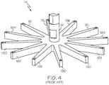
- FIG. 4 is an illustration of a MSF star 14 not forming part of the present invention and shaft 16 for a MSF system used to hold 12 specimens during mechanical testing.
- Each fixture arm 18A to 18L (generally 18) of the MSF star 14 extends from an axial fixture opening where the MSF star 14 is coupled to a central shaft 16.
- a fixture hub is disposed at the axial fixture opening and used to couple the MSF star 14 to the shaft 16.
- each specimen to be tested is attached proximate to the end of each fixture arm 18 at a specimen attachment location.
- one end of each specimen 20 is attached to the top side of a respective fixture arm 18 and the other end of the specimen 20 is attached to a load cell 15.
- Pre-load adjustment components used to achieve equal pre-loads before a test and the load cells 15 used to monitor the specimens during testing are provided at the stationary plate 17.
- the reciprocating vertical motion of the shaft 16 induces a reciprocating vertical motion of the MSF star 14 so that each specimen undergoes cyclic loading.
- the bath chamber provides the local environment for the MSF star 14 and attached specimens 20 which are limited in size by the dimensions of the bath chamber 12.
- the specimen zones 11 are equally distributed along a circle that is centered on the axis of the shaft 16.
- the circular array configuration is limited to a maximum of 12 specimens based on the specimen size and the dimensions of the bath chamber 12.
- a larger bath chamber is required.
- the MSF star may be required to have fewer fixture arms with greater spacing between the fixture arms.
- Some test protocols require testing a minimum number of specimens. For example, if 30 specimens are required to be tested and each MSF star 14 holds 12 specimens, then three test instruments are required to operate in parallel to complete testing in the minimum time. The cost of a test instrument may be prohibitively high. In such situations, fewer test instruments may be used to perform the required testing; however, the total time required to test all specimens is significantly increased as sequential test periods are required. For example, if only one test instrument is available and is limited to testing 12 specimens, the time necessary to complete testing of 30 specimens is three times that of a single test duration for the test instrument. Such delays in completing testing can be detrimental to product development, especially when the time required for a test instrument to complete mechanical testing of a set of specimens may be weeks.
- FIG. 5 is a perspective view of an example of a MSF star 70 according to the invention, wherein the MSF star 70 holds 16 specimens in a square array and which provides advantages over a conventional circular configuration 12 specimen MSF star.
- FIG. 6 shows a simplified plan view of the 16 specimen MSF star 70 inside the same size bath chamber box shown in FIG. 1B .
- Each specimen zone 72 is equal to or larger than the specimen zones 11 for the 12 specimen MSF star.
- the MSF star 70 includes 16 fixture arms 74 and 16 cross-members 76.
- Each fixture arm 74 extends radially from a fixture center and has a specimen zone 72 proximate to the arm end.
- Each cross-member 76 is in the form of a strut and has one end at a fixture arm 74 at a position between the fixture center and the arm end. Each cross-member 76 further includes an opposite end at an adjacent fixture arm 74 at a position between the fixture center and the arm end.
- the fixture arms 74 and cross-members 76 may be formed as a unitary object wherein the intervening open sections and other geometrical features are generated in a machining process.
- the MSF star 70 may be cast to its approximate shape and further processed with reduced machining requirements or generated using an additive manufacturing process. When a load is applied by a shaft that is coupled to the MSF star 70 at the axial fixture opening 77, the load is equally distributed to the specimen zones 72 despite the lack of radial symmetry.
- the gaps shown along the square perimeter between specimen zones 72A and 72P and specimen zones 72G and 72H are provided so that vertical posts supporting the upper portion of the test instrument do not significantly obscure any of the specimens during testing.
- the geometry of the square MSF star 70 is selected so that the deflection at each specimen attachment location within its specimen zone 72 is substantially identical. For example, a variation in the deflection at each specimen attachment location within approximately 0.025 mm (0.001 inch) means that the deflections are substantial identical or substantially equal.
- the thickness of the fixture arms 74 may differ. For example, longer fixture arms 74 may have a different thickness than shorter fixture arms 74.
- the locations of the cross-members 76 are selected to achieve a substantially identical distribution of the load applied by the shaft.
- the distance from a location where the cross-members 76 terminate at a fixture arm 74 to the end of that fixture arm 74 may be substantially identical (e.g., within + 0.003 in.) for all the fixture arms 74 as this is the region over which most of the deflection occurs.
- the fixture arms 74 have a cross-sectional shape such as a rectangle, square, triangular, round or oval shape, or an "I", "L” or “T” shape” selected to achieve a displacement at the specimen attachment location that is substantially equal to the displacement at each of the other specimen attachment locations.
- the fixture arms 74 may also be hollow (e.g., a tube).
- the cross-sectional shape may differ for different fixture arms 74 and different cross-members 76.
- the cross-sectional shape of each cross-member may be selected to achieve substantially equal displacements at all the specimen attachment locations.
- the geometrical characteristics (e.g., width, length and thickness) of diametrically-opposed fixture arms are identical.
- the geometrical characteristics of diametrically-opposed cross-members e.g., 76A and 761) may be identical.
- the MSF star 70 can be made from a variety of materials including, by non-exclusive examples, stainless steel, titanium and non-corrosive metals, and ceramics, composite materials and plastics.
- the openings defined within the MSF star 70 between the fixture arms 74 and cross-members 76 make the MSF star 70 lighter and reduce the disturbance to the bath solution as the MSF star 70 moves vertically during testing. Reduced weight is desirable to avoid limitations on the size of the linear motor used to drive the shaft and the number of specimens that may be accommodated.
- a non-exclusive listing of such feature parameters includes the length, width, angle, height and width bias of the outer portion of the fixture arms 74, the length, width, thickness, width bias thickness bias and web thickness of the inner portion of the fixture arms, and the width, height, thickness, thickness bias and web thickness of the cross-members.
- the 16 specimen MSF star 70 described above holds the specimens in a square array centered on the fixture center, it should be recognized that in alternative examples of an MSF star the specimens may be held in a rectangular array that is not a square array. Such a configuration is desirable, for example, for a rectangular (non-square) bath chamber.
- the illustrated MSF star 70 can be used to test 16 specimens, in other examples the MSF star is attached to a different number of specimens, including even or odd numbers of specimens.
- the MSF star exhibits quadrant symmetry for reduced complexity; however, this is not a requirement.
- a MSF star can include additional specimen zones disposed inside the rectangular array of zones described above.
- Such configurations include additional specimen zones along the fixture arms at positions that are closer to the axial fixture opening such that specimens at all the specimen zones experience a substantially equal load applied by the central shaft.
- the additional zones define a smaller rectangular array than the rectangular array defined by the other attachment zones.
- the available vertical test space for a specimen is a fixed value and is determined according to the length of the central shaft 16 that couples the MSF star 14 to the linear motor 22.
- a shaft of a certain length may be replaced by a shaft having a different length to obtain a different vertical test space.
- one shaft may provide a 50 mm test space while a longer shaft may provide a 100 mm test space.
- Replacing one shaft with another shaft to achieve a different test space typically involves a realignment of components (e.g., load cells) relative to the MSF star 14. This realignment may take several hours to several days for test personnel to perform. Realignment may be necessary, in part, due to the loss of the angular orientation (i.e., "clocking) position of the MSF star 14 relative to the axis of the shaft 16.
- FIG. 7 shows a MSF star 80, not according to claim 1, attached to a central shaft 82 in the axial opening of the MSF star using a locking collar 84 and clamp 86.
- the shaft 82 extends from a linear motor (not shown) used to impart vertical motion to the MSF star 80.
- a coupler 88 at the upper end of the shaft 82 is used to mechanically couple the MSF star 80 to the linear motor.
- the MSF star 80 is shown in the figure at a lower vertical position on the shaft 82 to accommodate a larger vertical specimen test space due to its greater distance from the upper attachment points and load cells (not shown).
- the shaft 82 can be used without the need for replacement when a different vertical test space is required.
- the MSF star 80 can be adjusted to any vertical position between a minimum and maximum vertical position and secured at the desired vertical position by the clamp 86.
- the clamp 86 is a split shaft clamp; however, other types of clamps may be used to secure the MSF star 80 at the desired vertical position.
- the MSF star 80 can be positioned higher on the shaft 82 for specimens utilizing a smaller vertical specimen test space.
- the shaft 82 includes one or more keyways to receive a key member that extends inwardly from the locking collar 84.
- the keyway can be in the form of a slot, spline or other feature formed in the cylindrical surface of the shaft 82 and does not extend around the full circumference of the shaft 82.
- the length of the keyway is parallel to the axis of the shaft 82.
- the keyway engages a key member extending from the locking collar 84 or MSF star 80 to prevent a loss of rotational alignment of the MSF star 80 relative to the shaft axis during vertical adjustments of the MSF star 80.
- the keyway may be a V-shaped slot or a slot having a rectangular cross-section.
- the key member may be a set screw or another component that extends from the MSF star 80 or locking collar 84 into the keyway.
- the key member is a spring-loaded member, and, in another preferred implementation, the key member includes a spherical surface that engages one or more surfaces of the keyway.
- FIG. 8A and FIG. 8B show a bottom-side perspective view and a cross-sectional view, respectively, of one example of a MSF star 90 attached to a central shaft 92.
- the locking collar 94 includes three threaded openings that each receive a spring-loaded ball set screw 96.
- FIG. 8B shows threaded openings 98 in the locking collar 94 that receive screws or bolts to secure the locking collar 94 to the MSF star 90.
- Also shown in FIG. 8B is one of the ball screws 96 driven inward into the one of three keyways 100 in the shaft 92 to lock the MSF star 90 into rotational position.
- the clamp 102 is loosened so that an operator can manually slide the MSF star 90 upward or downward to a different vertical position.
- the three ball screws 96 and respective keyways 100 prevent rotation of the MSF 90 about the shaft axis during a change in the vertical position.
- the locking collar is integrally formed with the MSF star as a single unitary structure. In another alternative, the locking collar and clamp may be formed as a single unitary component.
Landscapes
- Chemical & Material Sciences (AREA)
- Health & Medical Sciences (AREA)
- Physics & Mathematics (AREA)
- General Physics & Mathematics (AREA)
- Chemical Kinetics & Catalysis (AREA)
- Clinical Laboratory Science (AREA)
- Life Sciences & Earth Sciences (AREA)
- Analytical Chemistry (AREA)
- Biochemistry (AREA)
- General Health & Medical Sciences (AREA)
- Immunology (AREA)
- Pathology (AREA)
- Engineering & Computer Science (AREA)
- Automation & Control Theory (AREA)
- Investigating Strength Of Materials By Application Of Mechanical Stress (AREA)
Claims (11)
- Testhalterungsstern für mehrere Proben (70, 90), umfassend:eine Mehrzahl von Halterungsarmen (74), die sich jeweils radial von einer Halterungsmitte erstrecken und ein Armende mit einer Probenbefestigungsstelle (72) aufweisen; undeine Mehrzahl von Traversen (76), wobei jede Traverse (76) ein erstes Ende an einem Halterungsarm (74) an einer Position zwischen der Halterungsmitte und dem Armende aufweist und jede Traverse (76) ein zweites Ende an einem benachbarten der Halterungsarme (74) an einer Position zwischen der Halterungsmitte und dem Armende aufweist,so konfiguriert, dass bei Gebrauch eine Last, die von einer Welle (92) aufgebracht wird, die mit den Halterungsarmen (74) an der Halterungsmitte verbunden ist, gleichmäßig auf die Probenbefestigungsstellen (72) verteilt wird und wobei die Probenbefestigungsstellen (72) eine auf der Halterungsmitte zentrierte rechteckige Form definieren.
- Testhalterungsstern für mehrere Proben (70, 90) nach Anspruch 1, wobei sich die Halterungsarme (74) radial von einer axialen Halterungsöffnung an der Halterungsmitte erstrecken und wobei der Testhalterungsstern für mehrere Proben (70, 90) ferner eine Halterungsnabe umfasst, die an der axialen Öffnung angeordnet und dafür konfiguriert ist, den Testhalterungsstern für mehrere Proben mit der Welle (92) zu verbinden.
- Testhalterungsstern für mehrere Proben (70, 90) nach Anspruch 1, wobei, bei jedem der Halterungsarme (74), ein Querschnitt des Halterungsarms (74) dafür konfiguriert ist, eine Verschiebung an der Probenbefestigungsstelle (72) infolge der aufgebrachten Last, die im Wesentlichen gleich der Verschiebung an jeder der anderen Probenbefestigungsstellen (72) ist, zu erzielen.
- Testhalterungsstern für mehrere Proben (70, 90) nach Anspruch 3, wobei mindestens eine von einer Breite, einer Länge und einer Dicke mindestens eines Halterungsarms (74) anders ist als mindestens eine der Breite, der Länge und der Dicke mindestens eines anderen Halterungsarms (74).
- Testhalterungsstern für mehrere Proben (70, 90) nach Anspruch 1, wobei, bei jeder der Traversen (76), ein Querschnitt der Traverse (76) dafür konfiguriert ist, eine Verschiebung an der Probenbefestigungsstelle (72) infolge der aufgebrachten Last, die im Wesentlichen gleich der Verschiebung an jeder der anderen Probenbefestigungsstellen (72) ist, zu erzielen.
- Testhalterungsstern für mehrere Proben (70, 90) nach Anspruch 5, wobei mindestens eine von einer Breite, einer Länge und einer Dicke mindestens einer Traverse anders ist als mindestens eine der Breite, der Länge und der Dicke mindestens einer anderen Traverse.
- Testhalterungsstern für mehrere Proben (70, 90) nach Anspruch 1, wobei eine Breite, eine Länge und eine Dicke jedes Halterungsarms (74) dieselbe ist wie die Breite, die Länge und die Dicke eines diametral entgegengesetzten Halterungsarms (74).
- Testhalterungsstern für mehrere Proben (70, 90) nach Anspruch 1, wobei eine Breite, eine Länge und eine Dicke jeder Traverse (76) dieselbe ist wie die Breite, die Länge und die Dicke einer diametral entgegengesetzten Traverse (76).
- Testhalterungsstern für mehrere Proben (70, 90) nach Anspruch 1, wobei die rechteckige Form eine quadratische Form ist.
- Testhalterungsstern für mehrere Proben (70, 90) nach Anspruch 1, wobei die Probenbefestigungsstellen (72) erste Probenbefestigungsstellen sind, wobei der Testhalterungsstern für mehrere Proben ferner eine Mehrzahl von zweiten Probenbefestigungsstellen umfasst, die jeweils entlang einer Länge eines der Halterungsarme zwischen dem Armende und der Befestigungsnabe angeordnet sind, und der Testhalterungsstern für mehrere Proben (70, 90) so konfiguriert ist, dass bei Gebrauch die von der zentralen Welle (92) aufgebrachte Last gleichmäßig auf die ersten und zweiten Probenbefestigungsstellen verteilt wird.
- Testhalterungsstern für mehrere Proben (70, 90) nach Anspruch 10, wobei die zweiten Probenbefestigungsstellen eine auf der Halterungsmitte zentrierte rechteckige Anordnung definieren.
Applications Claiming Priority (1)
| Application Number | Priority Date | Filing Date | Title |
|---|---|---|---|
| US201962798134P | 2019-01-29 | 2019-01-29 |
Publications (2)
| Publication Number | Publication Date |
|---|---|
| EP3733293A1 EP3733293A1 (de) | 2020-11-04 |
| EP3733293B1 true EP3733293B1 (de) | 2021-11-03 |
Family
ID=69630111
Family Applications (1)
| Application Number | Title | Priority Date | Filing Date |
|---|---|---|---|
| EP20154237.0A Active EP3733293B1 (de) | 2019-01-29 | 2020-01-29 | Vorrichtung für ein testinstrument für mehrere proben |
Country Status (2)
| Country | Link |
|---|---|
| US (1) | US11559812B2 (de) |
| EP (1) | EP3733293B1 (de) |
Families Citing this family (5)
| Publication number | Priority date | Publication date | Assignee | Title |
|---|---|---|---|---|
| CN112730091B (zh) * | 2020-12-23 | 2023-03-21 | 北京机电工程研究所 | 一种试验件力热一体化试验加载装置和试验方法 |
| CN112834766B (zh) * | 2020-12-31 | 2022-06-24 | 赛乐进(绍兴)科技有限公司 | 免疫印迹仪及控制方法 |
| CN118935014B (zh) * | 2024-07-19 | 2025-04-04 | 温州市基安机械有限公司 | 一种注液阀门结构的性能测试装置 |
| CN118794796B (zh) * | 2024-08-15 | 2025-04-11 | 苏州宏洋纺织染整有限公司 | 一种纺织面料强度测试装置 |
| US20260202295A1 (en) * | 2025-01-10 | 2026-07-16 | Rtx Corporation | Multiple specimen high cycle fatigue test rig with individual load capability |
Family Cites Families (4)
| Publication number | Priority date | Publication date | Assignee | Title |
|---|---|---|---|---|
| US6536289B2 (en) | 2001-08-17 | 2003-03-25 | The Goodyear Tire & Rubber Company | Automated sample tester |
| EP2678664B1 (de) * | 2011-02-24 | 2019-08-07 | Gen-Probe Incorporated | Systeme und verfahren zur unterscheidung optischer signale mit verschiedenen modulationsfrequenzen bei einem optischen signaldetektor |
| CZ2016312A3 (cs) | 2016-05-26 | 2017-11-29 | Univerzita Pardubice | Přípravek k upevnění zkušebních vzorků v testovacím zařízení pro kontaktně únavové zkoušky materiálů |
| CN108072567B (zh) | 2017-12-08 | 2021-01-15 | 广州特种承压设备检测研究院 | 一种塑料恒温应力腐蚀实验装置及方法 |
-
2019
- 2019-12-13 US US16/713,176 patent/US11559812B2/en active Active
-
2020
- 2020-01-29 EP EP20154237.0A patent/EP3733293B1/de active Active
Also Published As
| Publication number | Publication date |
|---|---|
| US20200238290A1 (en) | 2020-07-30 |
| EP3733293A1 (de) | 2020-11-04 |
| US11559812B2 (en) | 2023-01-24 |
Similar Documents
| Publication | Publication Date | Title |
|---|---|---|
| US11559812B2 (en) | Apparatus for multi-specimen test instrument | |
| US8584538B2 (en) | Fatigue testing system for prosthetic devices | |
| US8006568B2 (en) | Fixture for mechanical analysis of a hollow tube | |
| Tkachenko et al. | An easy to assemble microfluidic perfusion device with a magnetic clamp | |
| US9913718B2 (en) | System for testing valves | |
| US10174858B2 (en) | Piezoelectric element-driven valve and flow rate control device including piezoelectric element-driven valve | |
| US9895664B2 (en) | Cartridge type hollow fiber membrane module | |
| US20090042281A1 (en) | Compound profiling devices, systems, and related methods | |
| US20130064738A1 (en) | Method and device for the metered addition of fluids into reaction vessels | |
| EP2473810B1 (de) | Wärmeübertragungssystem und verwendung davon | |
| US6645759B2 (en) | Apparatus for growing cells in culture under shear stress and/or strain | |
| US20100300181A1 (en) | Metering Station and Process for Metering Highly Viscous Liquids | |
| EP2795286B1 (de) | Vorrichtung zur mechanischen stimulation und charakterisierung biologischer proben | |
| US20180163886A1 (en) | Piezo actuator type valve | |
| Ude et al. | New perspectives in shake flask pH control using a 3D-printed control unit based on pH online measurement | |
| US20130084622A1 (en) | Device and method for continuous cell culture and other reactions | |
| ITTO20080426A1 (it) | Bioreattore, in particolare per la generazione di tessuti ingegnerizzati | |
| CN113438974A (zh) | 用于处理颗粒悬浮液的设备和方法 | |
| KR20200062798A (ko) | 금속의 수소취성 시험장치 | |
| CN106769587A (zh) | 一种多试样磨损试验装置 | |
| WO2011013067A2 (en) | Bio reactor for stem cells stimulation | |
| WO1992008919A1 (de) | Ventil | |
| CN105723144B (zh) | 冷凝液排出器 | |
| JPH07239045A (ja) | 流体計測装置のための、特に工業用インク及びペイントのための計測バルブ | |
| US20200253735A1 (en) | Modular and multifunctional apparatus for accelerated durability assessment of medical devices under cyclic pressure loading |
Legal Events
| Date | Code | Title | Description |
|---|---|---|---|
| PUAI | Public reference made under article 153(3) epc to a published international application that has entered the european phase |
Free format text: ORIGINAL CODE: 0009012 |
|
| STAA | Information on the status of an ep patent application or granted ep patent |
Free format text: STATUS: THE APPLICATION HAS BEEN PUBLISHED |
|
| AK | Designated contracting states |
Kind code of ref document: A1 Designated state(s): AL AT BE BG CH CY CZ DE DK EE ES FI FR GB GR HR HU IE IS IT LI LT LU LV MC MK MT NL NO PL PT RO RS SE SI SK SM TR |
|
| AX | Request for extension of the european patent |
Extension state: BA ME |
|
| STAA | Information on the status of an ep patent application or granted ep patent |
Free format text: STATUS: REQUEST FOR EXAMINATION WAS MADE |
|
| 17P | Request for examination filed |
Effective date: 20210427 |
|
| RBV | Designated contracting states (corrected) |
Designated state(s): AL AT BE BG CH CY CZ DE DK EE ES FI FR GB GR HR HU IE IS IT LI LT LU LV MC MK MT NL NO PL PT RO RS SE SI SK SM TR |
|
| RIN1 | Information on inventor provided before grant (corrected) |
Inventor name: CHINAVARE, JASON L |
|
| GRAP | Despatch of communication of intention to grant a patent |
Free format text: ORIGINAL CODE: EPIDOSNIGR1 |
|
| STAA | Information on the status of an ep patent application or granted ep patent |
Free format text: STATUS: GRANT OF PATENT IS INTENDED |
|
| INTG | Intention to grant announced |
Effective date: 20210719 |
|
| GRAS | Grant fee paid |
Free format text: ORIGINAL CODE: EPIDOSNIGR3 |
|
| GRAA | (expected) grant |
Free format text: ORIGINAL CODE: 0009210 |
|
| STAA | Information on the status of an ep patent application or granted ep patent |
Free format text: STATUS: THE PATENT HAS BEEN GRANTED |
|
| AK | Designated contracting states |
Kind code of ref document: B1 Designated state(s): AL AT BE BG CH CY CZ DE DK EE ES FI FR GB GR HR HU IE IS IT LI LT LU LV MC MK MT NL NO PL PT RO RS SE SI SK SM TR |
|
| REG | Reference to a national code |
Ref country code: GB Ref legal event code: FG4D |
|
| REG | Reference to a national code |
Ref country code: AT Ref legal event code: REF Ref document number: 1443486 Country of ref document: AT Kind code of ref document: T Effective date: 20211115 Ref country code: CH Ref legal event code: EP |
|
| REG | Reference to a national code |
Ref country code: IE Ref legal event code: FG4D |
|
| REG | Reference to a national code |
Ref country code: DE Ref legal event code: R096 Ref document number: 602020000869 Country of ref document: DE |
|
| REG | Reference to a national code |
Ref country code: LT Ref legal event code: MG9D |
|
| REG | Reference to a national code |
Ref country code: NL Ref legal event code: MP Effective date: 20211103 |
|
| REG | Reference to a national code |
Ref country code: AT Ref legal event code: MK05 Ref document number: 1443486 Country of ref document: AT Kind code of ref document: T Effective date: 20211103 |
|
| PG25 | Lapsed in a contracting state [announced via postgrant information from national office to epo] |
Ref country code: RS Free format text: LAPSE BECAUSE OF FAILURE TO SUBMIT A TRANSLATION OF THE DESCRIPTION OR TO PAY THE FEE WITHIN THE PRESCRIBED TIME-LIMIT Effective date: 20211103 Ref country code: LT Free format text: LAPSE BECAUSE OF FAILURE TO SUBMIT A TRANSLATION OF THE DESCRIPTION OR TO PAY THE FEE WITHIN THE PRESCRIBED TIME-LIMIT Effective date: 20211103 Ref country code: FI Free format text: LAPSE BECAUSE OF FAILURE TO SUBMIT A TRANSLATION OF THE DESCRIPTION OR TO PAY THE FEE WITHIN THE PRESCRIBED TIME-LIMIT Effective date: 20211103 Ref country code: BG Free format text: LAPSE BECAUSE OF FAILURE TO SUBMIT A TRANSLATION OF THE DESCRIPTION OR TO PAY THE FEE WITHIN THE PRESCRIBED TIME-LIMIT Effective date: 20220203 Ref country code: AT Free format text: LAPSE BECAUSE OF FAILURE TO SUBMIT A TRANSLATION OF THE DESCRIPTION OR TO PAY THE FEE WITHIN THE PRESCRIBED TIME-LIMIT Effective date: 20211103 |
|
| PG25 | Lapsed in a contracting state [announced via postgrant information from national office to epo] |
Ref country code: IS Free format text: LAPSE BECAUSE OF FAILURE TO SUBMIT A TRANSLATION OF THE DESCRIPTION OR TO PAY THE FEE WITHIN THE PRESCRIBED TIME-LIMIT Effective date: 20220303 Ref country code: SE Free format text: LAPSE BECAUSE OF FAILURE TO SUBMIT A TRANSLATION OF THE DESCRIPTION OR TO PAY THE FEE WITHIN THE PRESCRIBED TIME-LIMIT Effective date: 20211103 Ref country code: PT Free format text: LAPSE BECAUSE OF FAILURE TO SUBMIT A TRANSLATION OF THE DESCRIPTION OR TO PAY THE FEE WITHIN THE PRESCRIBED TIME-LIMIT Effective date: 20220303 Ref country code: PL Free format text: LAPSE BECAUSE OF FAILURE TO SUBMIT A TRANSLATION OF THE DESCRIPTION OR TO PAY THE FEE WITHIN THE PRESCRIBED TIME-LIMIT Effective date: 20211103 Ref country code: NO Free format text: LAPSE BECAUSE OF FAILURE TO SUBMIT A TRANSLATION OF THE DESCRIPTION OR TO PAY THE FEE WITHIN THE PRESCRIBED TIME-LIMIT Effective date: 20220203 Ref country code: NL Free format text: LAPSE BECAUSE OF FAILURE TO SUBMIT A TRANSLATION OF THE DESCRIPTION OR TO PAY THE FEE WITHIN THE PRESCRIBED TIME-LIMIT Effective date: 20211103 Ref country code: LV Free format text: LAPSE BECAUSE OF FAILURE TO SUBMIT A TRANSLATION OF THE DESCRIPTION OR TO PAY THE FEE WITHIN THE PRESCRIBED TIME-LIMIT Effective date: 20211103 Ref country code: HR Free format text: LAPSE BECAUSE OF FAILURE TO SUBMIT A TRANSLATION OF THE DESCRIPTION OR TO PAY THE FEE WITHIN THE PRESCRIBED TIME-LIMIT Effective date: 20211103 Ref country code: GR Free format text: LAPSE BECAUSE OF FAILURE TO SUBMIT A TRANSLATION OF THE DESCRIPTION OR TO PAY THE FEE WITHIN THE PRESCRIBED TIME-LIMIT Effective date: 20220204 Ref country code: ES Free format text: LAPSE BECAUSE OF FAILURE TO SUBMIT A TRANSLATION OF THE DESCRIPTION OR TO PAY THE FEE WITHIN THE PRESCRIBED TIME-LIMIT Effective date: 20211103 |
|
| PG25 | Lapsed in a contracting state [announced via postgrant information from national office to epo] |
Ref country code: SM Free format text: LAPSE BECAUSE OF FAILURE TO SUBMIT A TRANSLATION OF THE DESCRIPTION OR TO PAY THE FEE WITHIN THE PRESCRIBED TIME-LIMIT Effective date: 20211103 Ref country code: SK Free format text: LAPSE BECAUSE OF FAILURE TO SUBMIT A TRANSLATION OF THE DESCRIPTION OR TO PAY THE FEE WITHIN THE PRESCRIBED TIME-LIMIT Effective date: 20211103 Ref country code: RO Free format text: LAPSE BECAUSE OF FAILURE TO SUBMIT A TRANSLATION OF THE DESCRIPTION OR TO PAY THE FEE WITHIN THE PRESCRIBED TIME-LIMIT Effective date: 20211103 Ref country code: EE Free format text: LAPSE BECAUSE OF FAILURE TO SUBMIT A TRANSLATION OF THE DESCRIPTION OR TO PAY THE FEE WITHIN THE PRESCRIBED TIME-LIMIT Effective date: 20211103 Ref country code: DK Free format text: LAPSE BECAUSE OF FAILURE TO SUBMIT A TRANSLATION OF THE DESCRIPTION OR TO PAY THE FEE WITHIN THE PRESCRIBED TIME-LIMIT Effective date: 20211103 Ref country code: CZ Free format text: LAPSE BECAUSE OF FAILURE TO SUBMIT A TRANSLATION OF THE DESCRIPTION OR TO PAY THE FEE WITHIN THE PRESCRIBED TIME-LIMIT Effective date: 20211103 |
|
| REG | Reference to a national code |
Ref country code: DE Ref legal event code: R097 Ref document number: 602020000869 Country of ref document: DE |
|
| PG25 | Lapsed in a contracting state [announced via postgrant information from national office to epo] |
Ref country code: MC Free format text: LAPSE BECAUSE OF FAILURE TO SUBMIT A TRANSLATION OF THE DESCRIPTION OR TO PAY THE FEE WITHIN THE PRESCRIBED TIME-LIMIT Effective date: 20211103 |
|
| PLBE | No opposition filed within time limit |
Free format text: ORIGINAL CODE: 0009261 |
|
| STAA | Information on the status of an ep patent application or granted ep patent |
Free format text: STATUS: NO OPPOSITION FILED WITHIN TIME LIMIT |
|
| REG | Reference to a national code |
Ref country code: BE Ref legal event code: MM Effective date: 20220131 |
|
| 26N | No opposition filed |
Effective date: 20220804 |
|
| PG25 | Lapsed in a contracting state [announced via postgrant information from national office to epo] |
Ref country code: LU Free format text: LAPSE BECAUSE OF NON-PAYMENT OF DUE FEES Effective date: 20220129 Ref country code: AL Free format text: LAPSE BECAUSE OF FAILURE TO SUBMIT A TRANSLATION OF THE DESCRIPTION OR TO PAY THE FEE WITHIN THE PRESCRIBED TIME-LIMIT Effective date: 20211103 |
|
| PG25 | Lapsed in a contracting state [announced via postgrant information from national office to epo] |
Ref country code: SI Free format text: LAPSE BECAUSE OF FAILURE TO SUBMIT A TRANSLATION OF THE DESCRIPTION OR TO PAY THE FEE WITHIN THE PRESCRIBED TIME-LIMIT Effective date: 20211103 Ref country code: FR Free format text: LAPSE BECAUSE OF NON-PAYMENT OF DUE FEES Effective date: 20220131 Ref country code: BE Free format text: LAPSE BECAUSE OF NON-PAYMENT OF DUE FEES Effective date: 20220131 |
|
| REG | Reference to a national code |
Ref country code: DE Ref legal event code: R082 Ref document number: 602020000869 Country of ref document: DE Representative=s name: FORRESTERS IP LLP, DE Ref country code: DE Ref legal event code: R082 Ref document number: 602020000869 Country of ref document: DE Representative=s name: KUEHR, VERA, DIPL.-BIOL., DE |
|
| PG25 | Lapsed in a contracting state [announced via postgrant information from national office to epo] |
Ref country code: IE Free format text: LAPSE BECAUSE OF NON-PAYMENT OF DUE FEES Effective date: 20220129 |
|
| PG25 | Lapsed in a contracting state [announced via postgrant information from national office to epo] |
Ref country code: IT Free format text: LAPSE BECAUSE OF FAILURE TO SUBMIT A TRANSLATION OF THE DESCRIPTION OR TO PAY THE FEE WITHIN THE PRESCRIBED TIME-LIMIT Effective date: 20211103 |
|
| P01 | Opt-out of the competence of the unified patent court (upc) registered |
Effective date: 20230609 |
|
| P02 | Opt-out of the competence of the unified patent court (upc) changed |
Effective date: 20230619 |
|
| REG | Reference to a national code |
Ref country code: CH Ref legal event code: PL |
|
| REG | Reference to a national code |
Ref country code: DE Ref legal event code: R082 Ref document number: 602020000869 Country of ref document: DE Representative=s name: FORRESTERS IP LLP, DE |
|
| PG25 | Lapsed in a contracting state [announced via postgrant information from national office to epo] |
Ref country code: LI Free format text: LAPSE BECAUSE OF NON-PAYMENT OF DUE FEES Effective date: 20230131 Ref country code: CH Free format text: LAPSE BECAUSE OF NON-PAYMENT OF DUE FEES Effective date: 20230131 |
|
| PG25 | Lapsed in a contracting state [announced via postgrant information from national office to epo] |
Ref country code: MK Free format text: LAPSE BECAUSE OF FAILURE TO SUBMIT A TRANSLATION OF THE DESCRIPTION OR TO PAY THE FEE WITHIN THE PRESCRIBED TIME-LIMIT Effective date: 20211103 Ref country code: CY Free format text: LAPSE BECAUSE OF FAILURE TO SUBMIT A TRANSLATION OF THE DESCRIPTION OR TO PAY THE FEE WITHIN THE PRESCRIBED TIME-LIMIT Effective date: 20211103 |
|
| PG25 | Lapsed in a contracting state [announced via postgrant information from national office to epo] |
Ref country code: HU Free format text: LAPSE BECAUSE OF FAILURE TO SUBMIT A TRANSLATION OF THE DESCRIPTION OR TO PAY THE FEE WITHIN THE PRESCRIBED TIME-LIMIT; INVALID AB INITIO Effective date: 20200129 |
|
| PG25 | Lapsed in a contracting state [announced via postgrant information from national office to epo] |
Ref country code: MT Free format text: LAPSE BECAUSE OF FAILURE TO SUBMIT A TRANSLATION OF THE DESCRIPTION OR TO PAY THE FEE WITHIN THE PRESCRIBED TIME-LIMIT Effective date: 20211103 |
|
| PG25 | Lapsed in a contracting state [announced via postgrant information from national office to epo] |
Ref country code: TR Free format text: LAPSE BECAUSE OF FAILURE TO SUBMIT A TRANSLATION OF THE DESCRIPTION OR TO PAY THE FEE WITHIN THE PRESCRIBED TIME-LIMIT Effective date: 20211103 |
|
| PGFP | Annual fee paid to national office [announced via postgrant information from national office to epo] |
Ref country code: GB Payment date: 20251220 Year of fee payment: 7 |
|
| PGFP | Annual fee paid to national office [announced via postgrant information from national office to epo] |
Ref country code: DE Payment date: 20251217 Year of fee payment: 7 |