EP3733236A1 - Catheter and method for producing same - Google Patents
Catheter and method for producing same Download PDFInfo
- Publication number
- EP3733236A1 EP3733236A1 EP18897817.5A EP18897817A EP3733236A1 EP 3733236 A1 EP3733236 A1 EP 3733236A1 EP 18897817 A EP18897817 A EP 18897817A EP 3733236 A1 EP3733236 A1 EP 3733236A1
- Authority
- EP
- European Patent Office
- Prior art keywords
- layer
- insertion member
- catheter
- lumen
- material constituting
- Prior art date
- Legal status (The legal status is an assumption and is not a legal conclusion. Google has not performed a legal analysis and makes no representation as to the accuracy of the status listed.)
- Pending
Links
Images




Classifications
-
- A—HUMAN NECESSITIES
- A61—MEDICAL OR VETERINARY SCIENCE; HYGIENE
- A61M—DEVICES FOR INTRODUCING MEDIA INTO, OR ONTO, THE BODY; DEVICES FOR TRANSDUCING BODY MEDIA OR FOR TAKING MEDIA FROM THE BODY; DEVICES FOR PRODUCING OR ENDING SLEEP OR STUPOR
- A61M25/00—Catheters; Hollow probes
- A61M25/0009—Making of catheters or other medical or surgical tubes
-
- A—HUMAN NECESSITIES
- A61—MEDICAL OR VETERINARY SCIENCE; HYGIENE
- A61L—METHODS OR APPARATUS FOR STERILISING MATERIALS OR OBJECTS IN GENERAL; DISINFECTION, STERILISATION OR DEODORISATION OF AIR; CHEMICAL ASPECTS OF BANDAGES, DRESSINGS, ABSORBENT PADS OR SURGICAL ARTICLES; MATERIALS FOR BANDAGES, DRESSINGS, ABSORBENT PADS OR SURGICAL ARTICLES
- A61L29/00—Materials for catheters, medical tubing, cannulae, or endoscopes or for coating catheters
- A61L29/04—Macromolecular materials
- A61L29/049—Mixtures of macromolecular compounds
-
- A—HUMAN NECESSITIES
- A61—MEDICAL OR VETERINARY SCIENCE; HYGIENE
- A61M—DEVICES FOR INTRODUCING MEDIA INTO, OR ONTO, THE BODY; DEVICES FOR TRANSDUCING BODY MEDIA OR FOR TAKING MEDIA FROM THE BODY; DEVICES FOR PRODUCING OR ENDING SLEEP OR STUPOR
- A61M25/00—Catheters; Hollow probes
- A61M25/0021—Catheters; Hollow probes characterised by the form of the tubing
- A61M25/0023—Catheters; Hollow probes characterised by the form of the tubing by the form of the lumen, e.g. cross-section, variable diameter
- A61M25/0026—Multi-lumen catheters with stationary elements
-
- A—HUMAN NECESSITIES
- A61—MEDICAL OR VETERINARY SCIENCE; HYGIENE
- A61M—DEVICES FOR INTRODUCING MEDIA INTO, OR ONTO, THE BODY; DEVICES FOR TRANSDUCING BODY MEDIA OR FOR TAKING MEDIA FROM THE BODY; DEVICES FOR PRODUCING OR ENDING SLEEP OR STUPOR
- A61M25/00—Catheters; Hollow probes
- A61M25/0043—Catheters; Hollow probes characterised by structural features
- A61M25/0045—Catheters; Hollow probes characterised by structural features multi-layered, e.g. coated
-
- A—HUMAN NECESSITIES
- A61—MEDICAL OR VETERINARY SCIENCE; HYGIENE
- A61M—DEVICES FOR INTRODUCING MEDIA INTO, OR ONTO, THE BODY; DEVICES FOR TRANSDUCING BODY MEDIA OR FOR TAKING MEDIA FROM THE BODY; DEVICES FOR PRODUCING OR ENDING SLEEP OR STUPOR
- A61M25/00—Catheters; Hollow probes
- A61M25/01—Introducing, guiding, advancing, emplacing or holding catheters
- A61M25/0102—Insertion or introduction using an inner stiffening member, e.g. stylet or push-rod
-
- A—HUMAN NECESSITIES
- A61—MEDICAL OR VETERINARY SCIENCE; HYGIENE
- A61M—DEVICES FOR INTRODUCING MEDIA INTO, OR ONTO, THE BODY; DEVICES FOR TRANSDUCING BODY MEDIA OR FOR TAKING MEDIA FROM THE BODY; DEVICES FOR PRODUCING OR ENDING SLEEP OR STUPOR
- A61M25/00—Catheters; Hollow probes
- A61M25/01—Introducing, guiding, advancing, emplacing or holding catheters
- A61M25/09—Guide wires
-
- A—HUMAN NECESSITIES
- A61—MEDICAL OR VETERINARY SCIENCE; HYGIENE
- A61M—DEVICES FOR INTRODUCING MEDIA INTO, OR ONTO, THE BODY; DEVICES FOR TRANSDUCING BODY MEDIA OR FOR TAKING MEDIA FROM THE BODY; DEVICES FOR PRODUCING OR ENDING SLEEP OR STUPOR
- A61M25/00—Catheters; Hollow probes
- A61M25/10—Balloon catheters
-
- A—HUMAN NECESSITIES
- A61—MEDICAL OR VETERINARY SCIENCE; HYGIENE
- A61M—DEVICES FOR INTRODUCING MEDIA INTO, OR ONTO, THE BODY; DEVICES FOR TRANSDUCING BODY MEDIA OR FOR TAKING MEDIA FROM THE BODY; DEVICES FOR PRODUCING OR ENDING SLEEP OR STUPOR
- A61M25/00—Catheters; Hollow probes
- A61M25/10—Balloon catheters
- A61M25/1027—Making of balloon catheters
- A61M25/1029—Production methods of the balloon members, e.g. blow-moulding, extruding, deposition or by wrapping a plurality of layers of balloon material around a mandril
-
- A—HUMAN NECESSITIES
- A61—MEDICAL OR VETERINARY SCIENCE; HYGIENE
- A61L—METHODS OR APPARATUS FOR STERILISING MATERIALS OR OBJECTS IN GENERAL; DISINFECTION, STERILISATION OR DEODORISATION OF AIR; CHEMICAL ASPECTS OF BANDAGES, DRESSINGS, ABSORBENT PADS OR SURGICAL ARTICLES; MATERIALS FOR BANDAGES, DRESSINGS, ABSORBENT PADS OR SURGICAL ARTICLES
- A61L29/00—Materials for catheters, medical tubing, cannulae, or endoscopes or for coating catheters
- A61L29/14—Materials characterised by their function or physical properties, e.g. lubricating compositions
-
- A—HUMAN NECESSITIES
- A61—MEDICAL OR VETERINARY SCIENCE; HYGIENE
- A61M—DEVICES FOR INTRODUCING MEDIA INTO, OR ONTO, THE BODY; DEVICES FOR TRANSDUCING BODY MEDIA OR FOR TAKING MEDIA FROM THE BODY; DEVICES FOR PRODUCING OR ENDING SLEEP OR STUPOR
- A61M25/00—Catheters; Hollow probes
- A61M25/0043—Catheters; Hollow probes characterised by structural features
- A61M2025/0059—Catheters; Hollow probes characterised by structural features having means for preventing the catheter, sheath or lumens from collapsing due to outer forces, e.g. compressing forces, or caused by twisting or kinking
-
- A—HUMAN NECESSITIES
- A61—MEDICAL OR VETERINARY SCIENCE; HYGIENE
- A61M—DEVICES FOR INTRODUCING MEDIA INTO, OR ONTO, THE BODY; DEVICES FOR TRANSDUCING BODY MEDIA OR FOR TAKING MEDIA FROM THE BODY; DEVICES FOR PRODUCING OR ENDING SLEEP OR STUPOR
- A61M25/00—Catheters; Hollow probes
- A61M25/0009—Making of catheters or other medical or surgical tubes
- A61M25/0012—Making of catheters or other medical or surgical tubes with embedded structures, e.g. coils, braids, meshes, strands or radiopaque coils
-
- A—HUMAN NECESSITIES
- A61—MEDICAL OR VETERINARY SCIENCE; HYGIENE
- A61M—DEVICES FOR INTRODUCING MEDIA INTO, OR ONTO, THE BODY; DEVICES FOR TRANSDUCING BODY MEDIA OR FOR TAKING MEDIA FROM THE BODY; DEVICES FOR PRODUCING OR ENDING SLEEP OR STUPOR
- A61M25/00—Catheters; Hollow probes
- A61M25/0043—Catheters; Hollow probes characterised by structural features
- A61M25/005—Catheters; Hollow probes characterised by structural features with embedded materials for reinforcement, e.g. wires, coils, braids
-
- A—HUMAN NECESSITIES
- A61—MEDICAL OR VETERINARY SCIENCE; HYGIENE
- A61M—DEVICES FOR INTRODUCING MEDIA INTO, OR ONTO, THE BODY; DEVICES FOR TRANSDUCING BODY MEDIA OR FOR TAKING MEDIA FROM THE BODY; DEVICES FOR PRODUCING OR ENDING SLEEP OR STUPOR
- A61M25/00—Catheters; Hollow probes
- A61M25/10—Balloon catheters
- A61M25/1027—Making of balloon catheters
- A61M25/1036—Making parts for balloon catheter systems, e.g. shafts or distal ends
-
- A—HUMAN NECESSITIES
- A61—MEDICAL OR VETERINARY SCIENCE; HYGIENE
- A61M—DEVICES FOR INTRODUCING MEDIA INTO, OR ONTO, THE BODY; DEVICES FOR TRANSDUCING BODY MEDIA OR FOR TAKING MEDIA FROM THE BODY; DEVICES FOR PRODUCING OR ENDING SLEEP OR STUPOR
- A61M25/00—Catheters; Hollow probes
- A61M25/10—Balloon catheters
- A61M25/104—Balloon catheters used for angioplasty
Definitions
- the present invention relates to a catheter in which includes an outer tubular member and an insertion member and a method for producing the same. At least one of the outer tubular member or the insertion member is a multilayer tube having a first layer and a second layer laminated with the first layer.
- angioplasty for example, PTA and PTCA
- Angioplasty is a minimally invasive therapy that does not require thoracotomy, such as bypass surgery, thus is widely used.
- a preliminary step for the expansion of the stenosed part with a balloon catheter or a stent requires insertion of a guide wire into a lesion.
- a catheter including a tubular shaft into whose lumen a guide wire can be inserted.
- This catheter is required to have excellent slidability between the lumen of the shaft and the guide wire and excellent passability of guide wire.
- the catheter is also required to have flexibility so that it is unlikely to physically stimulate an inner wall of a blood vessel or the like.
- Such a catheter is exemplified by one including a shaft having an inner layer and an outer layer (for example, see Patent Documents 1 and 2).
- a shaft is flattened when the catheter is pressurized for such as to expand a balloon.
- This flattened shaft in some cases deteriorates slidability with a guide wire, which is inserted into a lumen of the shaft, and with a member disposed outside the shaft in a radial direction.
- a roundness (initial roundness) of the cross sectional shape of the shaft before using a catheter is low, the shaft is likely to be flat, and the slidability of the shaft tends to be low.
- an object of the present invention is to provide a catheter which is excellent in slidability and a shaft is hardly flattened after pressurization, and to provide a method for producing the catheter.
- a catheter of the present invention that has overcome the above problems has the following gist.
- a catheter having a distal side and a proximal side comprising:
- the second layer is preferably disposed more inside in a radial direction than the first layer.
- the insertion member is preferably the multilayer tube.
- the insertion member preferably has a first lumen into which a guide wire is inserted.
- the shaft preferably has a second lumen into which a fluid is supplied between the outside of the insertion member and the inside of the outer tubular member.
- a roundness of the insertion member after the pressure test calculated by the following equation (2) is 75% or more.
- an outer diameter reduction rate of the insertion member at a point where an outer diameter of the insertion member becomes smallest is within 10%.
- the point where the outer diameter of the insertion member becomes smallest is preferably inside the second lumen.
- the second lumen is preferably provided on the distal side of the shaft.
- the catheter of the present invention preferably comprising a balloon connected on the distal side of the second lumen.
- the shaft has a third lumen into which a fluid is supplied, and the catheter has a balloon which is connected to the third lumen, on the distal side of the shaft.
- a ratio of a Shore hardness of the material constituting the first layer to a Shore hardness of the material constituting the second layer is preferably 0.9 or more.
- the material constituting the first layer and the material constituting the second layer are preferably a thermoplastic resin.
- the material constituting the first layer is preferably a polyamide-based resin.
- the material constituting the second layer is preferably a polyolefin-based resin.
- the polyolefin-based resin is preferably a high-density polyethylene resin or a polypropylene resin.
- the second layer preferably has a layer A, and a layer B laminated with the layer A.
- the layer B preferably joins the first layer and the layer A.
- a material constituting the layer B is preferably a linear low-density polyethylene resin.
- the outer tubular member and the insertion member are preferably relatively movable in a distal and proximal direction.
- a method for producing the catheter of the present invention preferably comprising a step of producing by co-extrusion molding the multilayer tube having the first layer and the second layer laminated with the first layer.
- the catheter of the present invention can improve slidability between the outer tubular member and the insertion member or between the insertion member and the guide wire.
- the catheter can prevent the shaft from flattening after pressurization.
- FIG. 1 is a plan view showing the catheter of the present invention
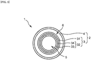
- FIG. 2 is a cross-sectional view showing the catheter in FIG. 1 that is taken along line II-II.
- FIG. 1 shows a configuration example of a catheter which a guide wire (hereinafter may be referred to as simply "GW") is inserted into a shaft from a proximal side to a distal side, which is so-called over-the-wire catheter.
- GW guide wire
- the catheter 1 has a proximal side and a distal side.
- the proximal side of the catheter 1 refers to a direction of a hand side of a user (operator) against an extension direction of the catheter 1
- the distal side refers to an opposite direction to the proximal side (that is, a direction of a treatment target side).
- a direction from the proximal side to the distal side of the catheter 1 is referred to as an axial direction.
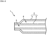
- the catheter 1 includes a shaft 2 having an outer tubular member 4 and an insertion member 3, and at least a part of the insertion member 3 in an axial direction thereof is disposed in the outer tubular member 4.
- the insertion member 3 may be a tubular shape similar to the outer tubular member 4 or may be a solid column shape. In a case where the insertion member 3 is the tubular shape, a guide wire may be inserted into a lumen thereof.
- At least one of the outer tubular member 4 or the insertion member 3 is a multilayer tube having a first layer 31 and a second layer 32 laminated with the first layer 31. That is, as shown in FIGs. 2 and 7 , either the insertion member 3 or the outer tubular member 4 may be the multilayer tube, or, though not illustrated, both the insertion member 3 and the outer tubular member 4 may be the multilayer tubes.
- a material constituting the second layer 32 has a higher crystallinity degree than that of a material constituting the first layer 31. Furthermore, at least one material included in the second layer 32 has preferably a higher crystallinity degree than that of at least one material included in the first layer 31. In addition, a material constituting the second layer 32 has a lower melting point than that of a material constituting the first layer 31. Furthermore, at least one material included in the second layer 32 has preferably a lower melting point than that of at least one material included in the first layer 31. This composition of the first layer 31 and the second layer 32 lowers a coefficient of friction on a contact surface between the insertion member 3 and the outer tubular member 4.
- Examples of a method for measuring the crystallinity degrees of the material constituting in the first layer 31 and the material constituting in the second layer 32 include densimetry, X-ray analysis, infrared spectroscopy, Raman spectroscopy, differential scanning calorimetry (DSC).
- the material constituting the second layer 32 merely needs to have a higher crystallinity degree than that of the material constituting the first layer 31, and may be no limitation is given to a crystallinity degree ratio of the material constituting the second layer 32 to the material constituting the first layer 31.
- the material constituting the second layer 32 has the crystallinity degree that is preferably 1.3 times or more, more preferably 2.0 times or more, and further preferably 3.0 times or more as high as that of the material constituting the first layer 31. Setting the lower limit of the crystallinity degree ratio of the material constituting the second layer 32 to the material constituting the first layer 31 to be within the above range can enhance tube hardness of the multilayer tube upon production thereof.
- the upper limit of the crystallinity degree ratio of the material constituting the second layer 32 to the material constituting the first layer 31 is preferably 10 times or less, more preferably 9 times or less, and further preferably 8 times or less. Setting the upper limit of the crystallinity degree ratio of the material constituting the second layer 32 to the material constituting the first layer 31 to be within the above range can reduce quench distortion and heat shrinkage of the multilayer tube upon production thereof, thus enabling flattening prevention to a great degree.
- the material constituting the second layer 32 merely needs to include a lower melting point (°C) than that of the material constituting the first layer 31.
- a melting point (°C) ratio of the material constituting the second layer 32 to the material constituting the first layer 31 is preferably 0.98 or less, more preferably 0.95 or less, further preferably 0.85 or less, and particularly preferably 0.8 or less.
- the upper limit of the melting point (°C) ratio of the material constituting the second layer 32 to the material constituting the first layer 31 can prevent quench distortion and heat shrinkage of the multilayer tube upon production thereof, consequently being able to prevent the multilayer tube from flattening.
- the lower limit of the melting point (°C) ratio of the material constituting the second layer 32 to the material constituting the first layer 31 may be, for example, 0.3 or more, 0.4 or more, or 0.5 or more.
- the melting point of the material constituting the second layer 32 is preferably lower than the material constituting the first layer 31 by 5°C or more, more preferably 10°C or more lower, further preferably 30°C or more lower, and particularly preferably 40°C or more lower. Setting the lower limit of a difference between the melting points of the material constituting the second layer 32 and of the material constituting the first layer 31 to be within the above range can reduce quench distortion and heat shrinkage of the multilayer tube upon production thereof, consequently rendering the multilayer tube unlikely to flatten. No limitation is given to the upper limit of the difference between the melting points of the material constituting the second layer 32 and of the material constituting the first layer 31. However, the upper limit may be, for example, 200°C or less, 190°C or less, or 180°C or less.
- At least one of the insertion member 3 or the outer tubular member 4 is the multilayer tube, and, in this multilayer tube, the first layer 31 and the second layer 32 have the above-described composition.
- This composition can reduce occurrence of flattening caused by quench distortion of the insertion member 3 and the outer tubular member 4, at least one of which is the multilayer tube, upon production of these members.
- the reduced occurrence of the flattening decreases contact area and then reduces friction between the outer surface of the insertion member 3 and the inner surface of the outer tubular member 4 and between the inner surface of the insertion member 3 and a GW, thus being able to prevent deterioration in slidability.
- the insertion member 3 and the outer tubular member 4 which become flat tend to be deformed in a radial direction when pressure is applied to a circumference of at least one of the insertion member 3 or the outer tubular member 4.
- This tendency leads to increase in friction between the outer surface of the insertion member 3 and the inner surface of the outer tubular member 4 and between the inner surface of the insertion member 3 and a GW, thus causing deterioration in slidability.
- This tendency is decreased when at least one of the insertion member 3 or the outer tubular member 4 is the multilayer tube that is prevented from flattening.
- Such a multilayer tube renders a cross-sectional shape of at least one of the insertion member 3 or the outer tubular member 4 unlikely to be deformed in the radial direction by pressure even though a fluid is supplied into the shaft 2. This prevents the increase in friction between the insertion member 3 and the outer tubular member 4 and between the insertion member 3 and a GW, thus being able to prevent deterioration in slidability.
- a ratio of a cross-sectional area of the second layer 32 to a cross-sectional area of the first layer 31 is 0.7 or less.
- a combination of such a cross-sectional area ratio of the second layer 32 to the first layer 31 and the above-described the material constituting respectively in the first layer 31 and the material constituting respectively in the second layer 32 prevents at least one of the insertion member 3 or the outer tubular member 4, which is the multilayer tube, from flattening, and reduces friction between the insertion member 3 and the outer tubular member 4 and between the insertion member 3 and a GW, thus being able to improve slidability.
- the ratio of the cross-sectional area of the second layer 32 to the cross-sectional area of the first layer 31 (the cross-sectional area of the second layer 32 / the cross-sectional area of the first layer 31) merely needs to be 0.7 or less.
- the ratio of the cross-sectional area of the second layer 32 to the cross-sectional area of the first layer 31 is preferably 0.55 or less, more preferably 0.40 or less, and further preferably 0.30 or less. Setting the upper limit of the cross-sectional area ratio of the second layer 32 to the first layer 31 in this manner can effectively prevent at least one of the insertion member 3 or the outer tubular member 4, which is the multilayer tube, from flattening.
- the multilayer tube has an initial roundness calculated by the equation (1) described below of 92% or more.
- the initial roundness represents a degree of flattening before use of the catheter 1, that is, before the shaft 2 is pressurized. Higher initial roundness of the multilayer tube can bring about less flattening.
- Such composition of the multilayer tube reduces the degree of flattening caused by quench distortion of the multilayer tube upon production thereof. The reduced degree of flattening renders the multilayer tube unlikely to be deformed in the radial direction by pressure even though a fluid is supplied into the shaft 2. This prevention can bring about excellent slidability.
- the initial roundness merely needs to be 92% or more but is preferably 95% or more, more preferably 95.5% or more, further preferably 96% or more, and particularly preferably 97% or more. Setting the initial roundness of the multilayer tube to be within the above range reduces the degree of flattening caused by quench distortion of the multilayer tube upon production thereof. The reduced degree of flattening renders the multilayer tube unlikely to be deformed in the radial direction by pressure even though a fluid is supplied into the shaft 2. This prevention can bring about excellent slidability.
- initial roundness % a minor axis outer diameter of the multilayer tube / a major axis outer diameter of the multilayer tube ⁇ 100
- the hub 20 includes a treatment part 22 communicating with a first lumen 5 that is an insertion passage for a GW and includes a fluid injection part 21 communicating with a second lumen 6 that is a flow passage for a fluid such as a pressurized fluid.
- the treatment part 22 can function as an injection port for a medicament or the like and as a suction port for a fluid or the like in a body lumen, in addition to the function for GW insertion.
- a leak valve To the second lumen 6 may be connected a leak valve.
- Such structure enables drainage of a fluid that is supplied into the second lumen 6, thus being preferable for safety.
- a check valve To the second lumen 6 may be connected a check valve. Such structure prevents backflow of a fluid that is supplied into the second lumen 6 towards a hand side.
- the leak valve and the check valve are preferably provided on the proximal side of the catheter 1.
- the hub 20 may be provided with a button and a lever to operate the leak valve and the check valve.
- a syringe for operating supply and drainage of a fluid into and from the second lumen 6.
- This syringe is preferably a small-diameter syringe for enhancement of operability but not particularly limited thereto.
- the insertion member 3, the outer tubular member 4, and the hub 20 can be joined together by a conventionally known joining means such as adhesive and heat welding. Amongst these, preference is given to junction by the heat welding. Such junction can eliminate leakage of a component of an adhesive, thus being able to produce the catheter 1 having high safety.
- the present invention may be applied to a so-called rapid exchange catheter in which a GW is inserted halfway from the proximal side to the distal side.
- the insertion passage for a GW may be provided on a part of the insertion member including the distal side of the shaft.
- the shaft 2 preferably has the second lumen 6 into which a fluid is supplied between the outside of the insertion member 3 and the inside of the outer tubular member 4.
- the shaft 2 having this structure can enhance rigidity of a distal end thereof owing to a fluid supplied into the second lumen 6, thus being able to improve pushability of the catheter 1.
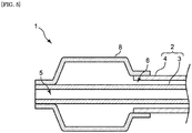
- the shaft 2 has on its distal side a balloon 8 communicating with the second lumen 6, such a fluid supply enables expansion of the balloon 8.
- the shaft 2 may just at least partly have double-tube structure (coaxial structure), this coaxial structure is preferably on the distal side of the shaft 2. That is, the shaft 2 is preferably provided with the second lumen 6 at least on the distal side thereof.
- the second lumen 6 entirely encloses a circumference of the shaft 2 so that an entire circumferential direction of the shaft 2 can be pressurized in a balanced manner upon supply of a fluid into the second lumen 6.
- This balanced pressurization can render flattening of the insertion member 3 and the outer tubular member 4 unlikely to occur.
- passability of a GW in a lesion depends largely upon rigidity of its distal side
- the shaft 2 having the second lumen 6 on the distal side thereof in this manner achieves favorable passability of a GW in a lesion.
- the outer tubular member 4 may be provided to enclose the outside of the insertion member 3 in an entire distal and proximal direction thereof. That is, the shaft 2 may have the coaxial structure in the entire distal and proximal direction of the insertion member 3. Alternatively, the shaft 2 may have the coaxial structure on the distal side and have biaxial structure on the proximal side.
- Rigidity of the entire shaft 2 may be varied in an axial direction thereof by changing, within a span of the second lumen 6 of the shaft 2, an inner diameter or an outer diameter of the insertion member 3, or an inner diameter or an outer diameter of the outer tubular member 4.
- Rigidity of the entire shaft 2 can also be varied by changing Shore D hardness of the material constituting the insertion member 3 or the outer tubular member 4 in the axial direction thereof.
- the Shore D hardness is measured in accordance with ISO868:2003 Testing Methods for Durometer Hardness of Plastics.
- Cross-sectional area of the second lumen 6 may be varied in a major axial direction by changing the outer diameter of the insertion member 3 or the inner diameter of the outer tubular member 4.
- the outer diameter of the insertion member 3 or the inner diameter of the outer tubular member 4 may increase or decrease towards the distal side. This can bring variation to an enhancement rate of rigidity of the shaft 2 in the axial direction upon supply of a fluid into the second lumen 6, thus being able to improve passability of the shaft 2 in a lesion.
- the second lumen 6 is preferably not provided on the distal end of the shaft 2. That is, a distal end of the second lumen 6 is preferably provided more proximally than the distal end of the shaft 2. Specifically, the distal end of the second lumen 6 is preferably provided on a position that is 1 mm or more proximal to the distal end of the shaft 2. This position is more preferably 3 mm or more, and further preferably 5 mm or more proximal to the distal end of the shaft 2. Such a position can prevent rigidity of the distal end of the shaft 2 from being excessively enhanced, thus being able to prevent the distal end from hurting a region other than a lesion owing to inadvertent contact.
- the distal end of the second lumen 6 that is excessively close to the proximal side might deteriorate pushability of a GW on the distal side.
- the distal end of the second lumen 6 is preferably provided on a position that is 35 mm or less proximal to the distal end of the shaft 2. This position is more preferably 30 mm or less proximal to the distal end of the shaft 2.
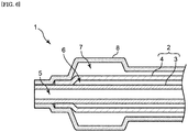
- the shaft 2 preferably has a third lumen 7 into which a fluid is supplied.
- the shaft 2 having this structure can much improve pushability of the shaft 2.
- the catheter 1 preferably further includes on the distal side of the shaft 2 a balloon 8 connected to the third lumen 7.
- the catheter 1 having this structure achieves excellent pushability and enables efficient expansion of a stenosed part of a blood vessel.
- the outer tubular member 4 and the insertion member 3 are preferably relatively movable in the distal and proximal direction. This means that the insertion member 3 can be, without any resistance, inserted into and also slid in a lumen of the outer tubular member 4.
- the outer tubular member 4 and the insertion member 3 that have such structure enable delivery of the insertion member 3, which has a smaller diameter than that of the outer tubular member 4, into a desired region in a body. The delivery of the insertion member 3 thereafter enables the outer tubular member 4 to easily reach, along the insertion member 3, the desired region.
- the insertion member 3 and the outer tubular member 4 may be joined together at a distal end part of the shaft 2. This joint suitably enhances rigidity of the distal end part of the shaft 2, thus being able to improve pushability.
- the insertion member 3 and the outer tubular member 4 are joined at the distal end part of the shaft 2 including the distal end of the shaft 2.
- the insertion member 3 and the outer tubular member 4 are joined more proximally than the distal end of the shaft 2.
- Such a joint of the insertion member 3 and the outer tubular member 4 can prevent rigidity of the distal end of the shaft 2 from being excessively enhanced, thus being able to prevent the distal end of the shaft 2 from hurting a region other than a lesion owing to inadvertent contact.
- rigidity is preferably varied gradually. Such variation in rigidity can enhance kink resistance of the shaft 2.
- Examples of structure that can gradually vary rigidity of the shaft 2 in the axial direction include one having the joint part at which the outer diameter of the outer tubular member 4 gradually increases towards the proximal side.
- the shaft 2 may have an end tip member at its distal end part. Providing the end tip member can prevent the distal end of the shaft 2 from hurting a region other than a lesion owing to inadvertent contact.
- the end tip member may be joined to either the insertion member 3 or the outer tubular member 4 but is more preferably joined to the outer tubular member 4 to allow gradual transition of flexibility of the shaft 2 in the axial direction.
- the end tip member preferably has lower Shore D hardness than that of at least one of the insertion member 3 or the outer tubular member 4. Such an end tip member can prevent the distal end part of the shaft 2 from hurting a region other than a lesion owing to inadvertent contact.
- the shaft 2 preferably has a radiopaque marker disposed on its distal side.
- the radiopaque marker is preferably provided on a distal side of the insertion member 3.
- the radiopaque marker is more preferably provided on a position that is 0 mm or more and 30 mm or less proximal to the distal end of the second lumen 6, and is further preferably provided on a position that is 0 mm or more and 5 mm or less proximal to the distal end of the second lumen 6. This renders it possible to check into where the shaft 2 is inserted.
- a conventionally known marker may be used.
- a radiopaque substance for the radiopaque marker may be, for example, lead, barium, iodine, tungsten, gold, platinum, iridium, stainless steel, titanium, a cobalt chromium alloy or the like.
- the catheter 1 includes the balloon 8 on its distal side
- the catheter 1 is preferably provided with one or more radiopaque markers in a vicinity of the balloon 8. This renders it possible to check where the balloon 8 is.
- the outer tubular member 4 may have a single layer or multiple layers in which the single layers are laminated. That is, the outer tubular member 4 may be the multilayer tube having the first layer 31 and the second layer 32.
- Examples of a method for producing the outer tubular member 4 having the first layer 31 and the second layer 32 include: a method of co-extrusion molding in which the material for the first layer 31 and the material for the second layer 32 are simultaneously extruded; and a method in which the first layer 31 is formed by, for example, coating one surface of an already prepared tubular member that is to be the second layer 32. Amongst these, preference is given to the method for producing by co-extrusion molding the outer tubular member 4 having the first layer 31 and the second layer 32. Such a method can produce the outer tubular member 4 in which the first layer 31 and the second layer 32 respectively have uniform thicknesses.
- the second layer 32 is preferably disposed to become the innermost layer of the outer tubular member 4.
- the outer tubular member 4 having this structure can improve slidability between the outer tubular member 4 and the insertion member 3.
- the outer tubular member 4 may be, for example, a resin tube extruded by extrusion molding.
- a resin forming the outer tubular member 4 include polyamide-based resin, polyester-based resin, polyurethane-based resin, polyolefin-based resin, fluorine-based resin, vinyl chloride-based resin, silicone-based resin and natural rubber. These may be used alone or in combination of two or more kinds. Amongst these, preference is given to the polyamide-based resin, the polyester-based resin, the polyurethane-based resin, the polyolefin-based resin and the fluorine-based resin.
- Rigidity of the outer tubular member 4 may be enhanced by adjusting thickness of the outer tubular member 4.
- the outer tubular member 4 according to the present invention has the thickness of preferably 0.02 mm or more, and more preferably 0.06 mm or more.
- the outer tubular member 4 has the thickness of preferably 1.00 mm or less, more preferably 0.50 mm or less, and further preferably 0.30 mm or less.
- the insertion member 3 may be the same tubular shape as that of the outer tubular member 4, or be a solid column shape.
- the insertion member 3 of the tubular shape can have the first lumen 5 inside in the radial direction, and into this first lumen 5 can be inserted or supplied a GW or a fluid.
- the insertion member 3 of the column shape can impart to itself a function of a GW.
- Examples of a cross-sectional shape of the insertion member 3 of the column shape include a circular shape, an oval shape and a polygonal shape. Amongst these, preference is given to the circular shape to improve slidability with the outer tubular member 4.
- the insertion member 3 may have a single layer or multiple layers in which the single layers are laminated. Amongst these, the insertion member 3 is preferably the multilayer tube having the first layer 31 and the second layer 32.
- the insertion member 3 having this structure can reduce contact areas between the outer surface of the insertion member 3 and the inner surface of the outer tubular member 4, and between the inner surface of the insertion member 3 and a GW and can reduce friction therebetween, thus being able to prevent deterioration in slidability.
- such structure renders the insertion member 3 unlikely to flatten and thus can achieve excellent slidability even though the insertion member 3 is pressurized by a fluid supplied into the shaft 2.
- a method for producing the insertion member 3 having the first layer 31 and the second layer 32 may be the above-exemplified method for producing the outer tubular member 4 having the first layer 31 and the second layer 32.
- both the insertion member 3 and the outer tubular member 4 are more preferably the multilayer tubes.
- the insertion member 3 and the outer tubular member 4 that are structured in this manner render both the insertion member 3 and the outer tubular member 4 unlikely to flatten, thus being able to much improve slidability between the insertion member 3 and the outer tubular member 4.
- the second layer 32 is preferably disposed to become the innermost layer of the insertion member 3.
- the insertion member 3 having this structure can improve slidability between a GW and the insertion member 3. It is also preferable that, the second layer 32 is disposed to become the outermost layer of the insertion member 3.
- the insertion member 3 having such structure can improve slidability between the outer tubular member 4 and the insertion member 3.
- the insertion member 3 preferably has the first lumen 5 into which a guide wire is inserted.
- the insertion member 3 having this structure enables insertion of a GW into the lumen of the insertion member 3, thus enabling the catheter 1 to easily reach an intended region such as a lesion.
- the insertion member 3 may be, for example, a resin tube or a columnar resin member that is extruded by extrusion molding.
- a resin forming the insertion member 3 may be the resin exemplified as one forming the outer tubular member 4.
- the insertion member 3 is the tubular shape
- rigidity of the insertion member 3 may be enhanced by adjusting thickness of the insertion member 3.
- a pressure for example, 14 to 30 atm
- an outer surface of a resin tube used as a shaft of a balloon catheter such a pressure deforms the tube in a radial direction.
- an inner surface of the tube comes into contact with a common GW having an outer diameter of approximately 0.356 mm to 0.39 mm, thus rendering the GW unlikely to slide in a distal and proximal direction along the tube in some cases.
- the insertion member 3 has a thickness of preferably 0.03 mm or more, and more preferably 0.05 mm or more.
- the insertion member 3 has the thickness of preferably 0.20 mm or less, more preferably 0.16 mm or less, and further preferably 0.12 mm or less to prevent the outer diameter of the insertion member 3 from becoming excessively large.
- a ratio of a Shore D hardness of the material constituting the outer tubular member 4 to a Shore hardness of the material constituting the insertion member 3 is preferably 0.9 or more, more preferably 1.0 or more, and further preferably 1.2 or more from a perspective of preventing the first lumen 5 from being deformed in the radial direction by pressure.
- the insertion member 3 preferably has high rigidity in order for its outer diameter not to be varied easily even though expansion pressure is increased to predetermined pressure or more.
- the high rigidity renders the insertion member 3 and the first lumen 5 into which a GW is inserted unlikely to be deformed in the radial direction by pressure even though a fluid is supplied into the second lumen 6. Consequently, this high rigidity can prevent deterioration in slidability.
- the insertion member 3 preferably has high uniformity between its inner and outer diameters in the radial direction in a cross-section perpendicular to the axial direction of the insertion member 3. That is, in the cross-section perpendicular to the axial direction of the insertion member 3, a difference of thickness in the first layer 31 and a difference of thickness in the second layer 32 in the radial direction of the insertion member 3 are preferably small.
- the maximum thickness in the first layer 31 in the radial direction of the insertion member 3 is preferably 1.20 times or less, more preferably 1.10 times or less, and further preferably 1.05 times or less as large as the minimum thickness in the first layer 31 in the cross-section perpendicular to the axial direction of the insertion member 3.
- the insertion member 3 having in the radial direction such a thickness in the first layer 31 can enhance uniformity between inner and outer diameters of the first layer 31.
- the maximum thickness in the second layer 32 in the radial direction of the insertion member 3 is preferably 1.20 times or less, more preferably 1.10 times or less, and further preferably 1.05 times or less as large as the minimum thickness in the second layer 32 in the cross-section perpendicular to the axial direction of the insertion member 3.
- the insertion member 3 having in the radial direction such a thickness in the second layer 32 can enhance uniformity between inner and outer diameters of the second layer 32.
- At least one of the first layer 31 or the second layer 32 having enhanced uniformity between its inner and outer diameters can enhance uniformity between the inner and outer diameters of the insertion member 3 in the radial direction.
- a thickness ratio of the second layer 32 to the first layer 31 (the thickness of the second layer 32/the thickness of the first layer 31) in the radial direction of the insertion member 3 is preferably 0.20 or more, more preferably 0.22 or more, and further preferably 0.25 or more in the cross-section perpendicular to the axial direction of the insertion member 3. Setting the lower limit of the thickness ratio of the second layer 32 to the first layer 31 in this manner enables stable formation of the second layer 32 without breakage.
- the thickness ratio of the second layer 32 to the first layer 31 (the thickness of the second layer 32/the thickness of the first layer 31) in the radial direction of the insertion member 3 is preferably 0.60 or less, more preferably 0.50 or less, further preferably 0.40 or less, and particularly preferably 0.35 or less in the cross-section perpendicular to the axial direction of the insertion member 3. Setting the upper limit of the thickness ratio of the second layer 32 to the first layer 31 in this manner can reduce flattening occurrence of the insertion member 3 caused by quench distortion upon production of the insertion member 3 and can simultaneously enhance uniformity between the inner and outer diameters of the insertion member 3 in the radial direction.
- the insertion member 3 has a roundness after pressure test, which is calculated by the following equation (2) after pressure test, of preferably 75% or more in the cross-section perpendicular to the axial direction of the insertion member 3.
- the roundness after pressure test represents a degree of flattening of the insertion member 3 after use of the catheter 1, and the use of the catheter 1 is simulated by pressure test in which the second lumen 6 is repeatedly pressurized.
- the pressure test is performed by the following steps.
- the core material may be a GW or be a core material of stainless steel, a nickel alloy, a titanium alloy, or the like that resembles a GW. Amongst these, preference is given to the stainless steel core material owing to its easy handleability.
- a pressurized medium is 37°C water.
- the pressurized medium may be a fluid of another kind.
- Examples of the pressurized medium include a liquid such as saline, and a gas such as air and a nitrogen gas.
- a temperature of the pressurized medium may optionally be higher or lower than 37°C, or the like to perform the test simulating a severe environment.
- the pressure which is the rated burst pressure (RBP) of the catheter 1 plus 1 atm of atmospheric pressure, is applied to within the second lumen 6 for 30 seconds.
- This pressure applies a load that deforms the insertion member 3 in the radial direction.
- the RBP is the maximum balloon inflation pressure of a balloon catheter that can be statistically guaranteed.
- 1 atm is 1013hPa.
- step (iv) the pressure within the second lumen 6 is depressurized to 1 atm (atmospheric pressure).
- step (iii) and the step (iv) are repeated 20 times in total. This step (v) enables confirmation of a degree to which the insertion member 3 flattens when a fluid is repeatedly supplied into the second lumen 6.
- roundness after pressure test of the insertion member 3 can be calculated by the following equation (2).
- roundness after pressure test % an outer diameter of the insertion member 3 after the the pressure test at the point of the minor axis outer diameter thereof upon the calculation of the initial roundness / an outer diameter of the insertion member 3 after the pressure test at the point of the major axis outer diameter thereof upon the calculation of the initial roundness ⁇ 100
- a minor axis outer diameter and a major axis outer diameter are measured after the pressure test at the point where the minor axis outer diameter and the major axis outer diameter of the insertion member 3 are measured upon the calculation of the initial roundness.
- the measured values are assigned to the above equation (2) to determine the roundness after pressure test.
- the insertion member 3 having a higher roundness after pressure test can ostensibly cause less flattening of the shaft 2 after pressurization.
- the insertion member 3 is preferably the roundness after pressure test of 75% or more in the cross-section perpendicular to the axial direction of the insertion member 3.
- the roundness after pressure test is preferably 80% or more, more preferably 85% or more, and further preferably 90% or more. Setting the roundness after pressure test of the insertion member 3 to be within the above range reduces deformation of the insertion member 3 in the radial direction after repeated supply of a fluid into the second lumen 6, thus enabling excellent slidability of the insertion member 3.
- an outer diameter reduction rate of the insertion member 3 at a point where the outer diameter of the insertion member 3 becomes smallest is preferably within 10%.
- the outer diameter reduction rate is more preferably within 8%, and further preferably within 6%. Setting the outer diameter reduction rate of the insertion member at the point where the outer diameter of the insertion member 3 becomes smallest to be within the above range renders the first lumen 5 into which a GW is inserted unlikely to be deformed in the radial direction by pressure even though a fluid is supplied into the second lumen 6. Consequently, deterioration in slidability of a GW can be prevented.
- the point where the outer diameter of the insertion member 3 becomes smallest is preferably inside the second lumen 6. This renders the first lumen 5 into which a GW is inserted unlikely to be deformed in the radial direction by pressure even though a fluid is supplied into the second lumen 6. Consequently, deterioration in slidability of a GW can be prevented.
- the point where the outer diameter of the insertion member 3 becomes smallest is preferably on the distal side of the shaft 2.
- the point is more preferably on a position that is 0 cm or more and 100 cm or less, and further preferably 0 cm or more and 60 cm or less proximal to the distal end of the shaft 2. This enhances rigidity of the distal side of the shaft 2, thus improving passability of a GW in a lesion.
- the material constituting the first layer 31 include: a polyamide-based resin such as nylon 12, a nylon 12 elastomer, nylon 6 and aromatic polyamide; a polyimide-based resin; a polyurethane-based resin such as thermoplastic polyurethane; a crystalline thermoplastic resin such as a polyetheretherketone resin and a fluorine-based resin such as polyvinylidene fluoride and polyvinyl fluoride; an amorphous thermoplastic resin such as a polystyrene resin, polyvinyl chloride and an acrylic resin; a thermosetting resin such as a silicone-based resin; and natural rubber. These may be used alone or in combination of two or more kinds.
- thermoplastic resin owing to its easy handleability. More preference is given to the polyamide-based resin, and further preference is given to the nylon 12 and the nylon 12 elastomer. Owing to such at least one material included in the first layer 31, the first layer 31 has a high melting point and a low crystallinity degree. This reduces occurrence of quench distortion of the first layer 31, thus being able to prevent its slidability from deteriorating.
- the material constituting the second layer 32 include: a non-polar polyolefin-based resin such as polyethylene and polypropylene; a polyamide-based resin such as nylon 12, a nylon 12 elastomer, nylon 6 and aromatic polyamide; a polyester-based resin such as a polyetheretherketone resin and polyethylene terephthalate; a thermoplastic resin such as a fluororesin such as polytetrafluoroethylene; a silicone-based resin; and natural rubber. These may be used alone or in combination of two or more kinds. Amongst these, preference is given to the thermoplastic resin owing to its easy handleability. More preference is given to the non-polar polyolefin-based resin.
- a polyethylene-based resin such as high-density polyethylene, medium-density polyethylene and low-density polyethylene, and particular preference is given to the high-density polyethylene and the low-density polyethylene. Owing to such at least one material included in the second layer 32, a surface of the second layer 32 becomes slippery, thus being able to much improve its slidability.
- a classification of the polyethylene such as the high-density polyethylene and the low-density polyethylene is based upon JIS K6922-1 that defines polyethylene having a density of 910 kg/m3 or more and less than 930 kg/m3 as the low-density polyethylene; polyethylene having a density of 930 kg/m3 or more and less than 942 kg/m3 as the medium-density polyethylene; and polyethylene having a density of 942 kg/m3 or more as the high-density polyethylene.
- the material constituting the first layer 31 and the material constituting the second layer 32 are preferably a thermoplastic resin. Such materials constituting the first layer 31 and the second layer 32 facilitate lamination of the first layer 31 and the second layer 32 and also strengthen the lamination of the first layer 31 and the second layer 32.
- the second layer 32 is preferably disposed more inside in the radial direction than the first layer 31.
- the second layer 32 having this structure prevents the multilayer tube from flattening and can improve slidability with a GW and the insertion member 3 that are disposed inside the multilayer tube in the radial direction.
- the second layer 32 is also preferably disposed more outside in the radial direction than the first layer 31.
- the second layer 32 having this structure renders the multilayer tube unlikely to be deformed by pressure when the pressure is applied to the multilayer tube from its outside in the radial direction.
- a ratio of a Shore D hardness of the material constituting the first layer 31 to a Shore D hardness of the material constituting the second layer 32 is preferably 0.9 or more.
- the Shore D hardness ratio is more preferably 1.0 or more, and further preferably 1.1 or more. Setting the lower limit of the ratio of the Shore D hardness of the material constituting the first layer 31 to the Shore D hardness of the material constituting the second layer 32 in this manner can prevent the multilayer tube from being deformed by pressure and then from causing deterioration in its slidability when the pressure is applied to the multilayer tube.
- the upper limit of the ratio of the Shore D hardness of the material constituting the first layer 31 to the Shore D hardness of the material constituting the second layer 32 is not limited but is, for example, preferably 3.0 or less, more preferably 2.5 or less, and further preferably 2.0 or less. Setting the upper limit of the ratio of the Shore D hardness of the material constituting the first layer 31 to the Shore D hardness of the material constituting the second layer 32 in this manner imparts moderate flexibility to the multilayer tube, thus achieving the catheter 1 that easily passes a stenosed part of a blood vessel.
- the second layer 32 may have a layer A 33 and a layer B 34 laminated with the layer A 33.
- the insertion member 3 has the first layer 31 and the second layer 32, and the second layer 32 may have the layer A 33 and the layer B 34.
- the outer tubular member 4 has the first layer 31 and the second layer 32, and the second layer 32 may have the layer A 33 and the layer B 34.
- At least one of the insertion member 3 or the outer tubular member 4 has, from its outside in the radial direction, three layers that are the first layer 31, the layer B 34 and the layer A 33, or that are the layer A 33, the layer B 34 and the first layer 31, and the layer B 34 may join the first layer 31 and the layer A 33.
- the first layer 31 is one side of at least one of the insertion member 3 or the outer tubular member 4
- the layer A 33 is another side of the insertion member 3.
- This structure can join the first layer 31 and the layer A 33 via the layer B 34 even though the at least one material included in the first layer 31 and a material forming the layer A 33 are difficult to be joined.
- the layer B 34 is formed from a material that can be joined to both the at least one material included in the first layer 31 and the material forming the layer A 33. Disposing such a layer B 34 between the first layer 31 and the layer A 33 enables junction of the first layer 31a and the layer A 33.
- Examples of a method for producing the second layer 32 having the layer A 33 and the layer B 34 include a method of co-extrusion molding in which the respective materials for the first layer 31, the layer A 33 and the layer B 34 are simultaneously extruded; and a method in which the layer B 34 is formed by, for example, coating the outside of an already prepared tubular member that is to be the layer A 33, and then the first layer 31 is formed by, for example, coating the outside of the layer B 34.
- Such a method can produce the first layer 31, the layer A 33 and the layer B 34 that respectively have uniform thicknesses.
- the material constituting the layer A 33 preferably has a higher Shore D hardness than that of the material constituting the layer B 34.
- the layer A 33 constitutes one side of the multilayer tube in the radial direction, and thus this side of the multilayer tube can have high firmness. This high firmness can prevent the multilayer tube from being deformed in the radial direction by pressure when a fluid is supplied into the second lumen 6.
- the Shore D hardness of the material constituting the layer A 33 is preferably 1.2 times or more, more preferably 1.3 times or more, and further preferably 1.4 times or more as high as a Shore D hardness of the material constituting the layer B 34. Setting the Shore D hardness of the material constituting the layer A 33 to be within the above range can increase firmness of the one side of the multilayer tube. This increased firmness can prevent the multilayer tube from being deformed by pressure when a fluid is supplied into the second lumen 6.
- the Shore D hardness of the material constituting the layer A 33 is preferably more than 1.0 time, more preferably 1.1 times or more, and further preferably 1.2 times or more as high as the Shore D hardness of the material constituting the first layer 31. Setting the Shore D hardness of the material constituting the layer A 33 to be within the above range can increase firmness of the one side of the multilayer tube. This increased firmness can prevent the multilayer tube from being deformed in the radial direction by pressure when a fluid is supplied into the second lumen 6.
- the material constituting the layer A 33 include a polyolefin-based resin such as polyethylene and polypropylene; a polyester-based resin such as polyethylene terephthalate; and a fluorine-based resin such as polytetrafluoroethylene.
- a polyethylene-based resin owing to its slippery surface. More preference is given to a non-adhesive polyethylene resin, and further preference is given to a non-adhesive high-density polyethylene resin. This can improve slidability of the multilayer tube. Further, by increasing firmness of the layer A 33, the multilayer tube can be prevent from being deformed in the radial direction by pressure.
- the material constituting the layer B 34 include a polyethylene-based resin such as low-density polyethylene and linear low-density polyethylene.
- a polyethylene-based resin such as low-density polyethylene and linear low-density polyethylene.
- a difference of thickness in the layer A 33 and a difference of thickness in the layer B 34 in the radial direction of the multilayer tube are preferably small in the cross-section perpendicular to the axial direction of the multilayer tube.
- the maximum thickness in the layer A 33 in the radial direction of the multilayer tube is preferably 1.20 times or less, more preferably 1.10 times or less, and further preferably 1.05 times or less as large as the minimum thickness in the layer A 33 in the cross-section perpendicular to the axial direction of the multilayer tube.
- the layer A 33 having such a thickness in the radial direction of the multilayer tube can enhance uniformity between its inner and outer diameters.
- the maximum thickness in the layer B 34 in the radial direction of the multilayer tube is preferably 1.20 times or less, more preferably 1.10 times or less, and further preferably 1.05 times or less as large as the minimum thickness in the layer B 34.
- the layer B 34 having such a thickness in the radial direction of the multilayer tube can enhance uniformity between its inner and outer diameters. Enhancing uniformity between the inner and outer diameters of at least one of the layer A 33 or the layer B 34 enhances uniformity between the inner and outer diameters of the second layer. This enhanced uniformity can consequently enhance inner and outer diameters of the multilayer tube in the radial direction.
- the multilayer tube preferably has in the radial direction a thickness ratio of the layer B 34 to the layer A 33 (the thickness of the layer B 34 /the thickness of the layer A 33) of 0.1 or more, more preferably 0.3 or more, and further preferably 0.5 or more in the cross-section perpendicular to the axial direction of the multilayer tube. Setting the lower limit of the thickness ratio of the layer B 34 to the layer A 33 in this manner enables the layer B 34 to sufficiently join the layer A 33 and the first layer.
- the multilayer tube preferably has in the radial direction the thickness ratio of the layer B 34 to the layer A 33 (the thickness of the layer B 34 /the thickness of the layer A 33) of 1.2 or less, more preferably 1.1 or less, and further preferably 1.0 or less. Setting the upper limit of the thickness ratio of the layer B 34 to the layer A 33 in this manner leads to sufficient firmness of the layer A 33.
- the catheter 1 preferably includes the balloon 8 connected on a distal side of the second lumen 6.
- the catheter 1 including the balloon 8 can efficiently expand a stenosed part of a blood vessel. Expanding the balloon 8 in a normal blood vessel before (proximal to) a stenosed part or in a concomitantly used guiding catheter prevents an unexpected shift in position of the catheter 1 in its major axial direction upon operation of a GW. This prevention can further enhance capability of a GW as a backup.
- a material constituting the balloon 8 may be, for example, the material that forms the first layer 31 but is not particularly limited thereto.
- the balloon 8 can be produced to have the same size, shape or the like as that of a balloon of a known balloon catheter.
- a production method of a known balloon can be adopted.
- the balloon 8 may be provided with a reinforcement, a scoring member, cutting member, a medicament layer or a hydrophilic coating layer.
- At least one of the insertion member 3 or the outer tubular member 4 preferably includes a stiffener to enhance rigidity of the insertion member 3 and the outer tubular member 4.
- FIG. 8 is a cross-sectional view showing an example of the insertion member 3 provided with the stiffeners.
- the stiffener 10 is, for example, preferably a wire provided inside at least one of the insertion member 3 or the outer tubular member 4.
- the stiffener 10 is the wire
- at least part of the wire is preferably embedded in a wall of at least one of the insertion member 3 and the outer tubular member 4.
- the stiffener 10 provided in this manner can sufficiently enhance rigidity of the insertion member 3 and the outer tubular member 4.
- the wire used as the stiffener 10 may be, for example, a single metal wire or a twisted metal wire of stainless steel, titanium, a cobalt-chrome alloy or the like.
- the wire may also be a fiber material, such as a polyarylate fiber, an aramid fiber, an ultrahigh molecular weight polyethylene fiber, a PBO fiber and a carbon fiber.
- the fiber material may be a monofilament or a multifilament.
- the wire preferably has higher elasticity than that of the insertion member 3 from a perspective of achieving high firmness of the insertion member 3. For the same reason, the stiffener 10 preferably has higher Shore hardness than that of the insertion member 3.
- the stiffener 10 may be one or more spirally arranged wires or a combination of these along an axial direction inside the insertion member 3 and the outer tubular member 4.
- the stiffener 10 is preferably the wires that are bundled without being woven or the wires that are plaited to further enhance rigidity of the stiffener 10. Amongst these, preference is given to the plaited wires.
- the stiffener 10 may contain a radiopaque substance to render it possible under roentgenoscopy to check where the insertion member 3 and the outer tubular member 4 are.
- the radiopaque substance may be the above-described material. Such a radiopaque substance enables the stiffener 10 to function as a radiopaque marker.
- a method for producing the catheter according to the present invention includes a step of producing by co-extrusion molding the multilayer tube having the first layer 31 and the second layer 32 laminated with the first layer 31.
- the multilayer tube is preferably produced by coextruding the at least one material for the first layer 31 and the at least one material for the second layer 32 simultaneously. Producing the multilayer tube in this manner can lead to uniform thicknesses of both the first layer 31 and the second layer 32, thus further facilitating firm junction of the first layer 31 and the second layer 32.
- a second lumen 6 was provided on a distal side of a shaft 2 and a distal end of the second lumen 6 was proximal to a distal end of the shaft 2.
- the measurement was performed with an insertion member and an outer tubular member that were respectively prepared.
- Firstly prepared by co-extrusion was the insertion member of a tubular shape that had a first layer and a second layer having a layer A and a layer B.
- These layers constituted three-layer structure in which the first layer, the layer B and the layer A were arranged in order from the outside in a radial direction.
- the prepared insertion member was subjected to an annealing treatment at 80°C for 1 hour.
- the first layer was nylon 12 (Nylon 12, Rilsamid (registered trademark) AESNO MED; Arkema, melting point: 169°C, crystallinity degree: 20%, and Shore D hardness: 74).
- the layer B was linear low-density polyethylene (LLDPE, Plexar (registered trademark) PX3080; Equistar Chemical, melting point: 127°C, and crystallinity degree: 40%).
- the layer A was high-density polyethylene (HDPE, Novatec (registered trademark) HB530; Japan Polyethylene Corporation, melting point: 136°C, crystallinity degree: 75%, and Shore D hardness: 71).
- the prepared insertion member had an outer diameter of 0.65 mm and an inner diameter of 0.45 mm. From outer diameters and thicknesses of the first layer and the second layer were respectively determined cross-sectional areas of the first layer and the second layer, and from these cross-sectional areas was calculated a cross-sectional area ratio of the second layer to the first layer. In addition, a minor axis outer diameter and a major axis outer diameter of the insertion member were measured, and from these measured diameters was calculated the initial roundness.
- the outer tubular member was prepared by extrusion molding with nylon 12 (Nylon 12, Rilsamid (registered trademark) AESNO MED; Arkema, melting point: 169°C, crystallinity degree: 20%, and Shore D hardness: 74).
- the prepared outer tubular member had an outer diameter of 1.50 mm and an inner diameter of 1.00 mm.
- the outer tubular member is disposed outside the insertion member in the radial direction, and a pressure test was performed by the following steps.
- the RBP was 30 atm.
- the applied pressure was 31 atm of absolute pressure.
- the core material was a ⁇ 0.36 mm stainless steel core material resembling a GW.
- a major axis outer diameter and a minor axis outer diameter of the insertion member were measured, and from the measured diameters was calculated the roundness after pressure test. This measurement was performed at the same point where the minor axis outer diameter and the major axis outer diameter of the insertion member had been measured upon the calculation of the initial roundness.
- Example 1 Comparative Example 1 Comparative Example 2 First Layer Material Nylon 12 Nylon 12 Nylon 12 Nylon 12 Melting Point (°C) 169 169 169 169 Crystallinity Degree (%) 20 20 20 20 Shore D Hardness 74 74 74 74 Thickness ( ⁇ m) 80 70 50 100 Cross-sectional Area (mm 2 ) 0.143 0.127 0.094 0.173 Second Layer Layer B Material LLDPE LLDPE LLDPE - Melting Point (°C) 127 127 127 - Crystallinity Degree (%) 40 40 40 - Composition Shore D Hardness - - - - Thickness ( ⁇ m) 10 10 10 - Layer A Material HDPE HDPE HDPE - Melting Point (°C) 136 136 - Crystallinity Degree (%) 75 75 75 - Shore D Hardness 71 71 71 - Thickness ( ⁇ m) 10 20 40 -
- Example 1 employed an insertion member in which thicknesses of a first layer, a layer B and a layer A were 80 ⁇ m, 10 pm and 10 ⁇ m respectively.
- a catheter in Example 1 had a smaller cross-sectional area ratio of a second layer to the first layer than that of a catheter in Comparative Example 1.
- the insertion member of the catheter in Example 1 had both a high initial roundness and a high roundness after pressure test.
- Example 2 employed an insertion member in which thicknesses of a first layer and a layer A were 70 pm and 20 pm respectively.
- a catheter in Example 2 had also a smaller cross-sectional area ratio of a second layer to the first layer than that of a catheter in Comparative Example 1.
- the insertion member of the catheter in Example 2 had a high initial roundness and a high roundness after pressure test.
- Comparative Example 1 employed an insertion member in which thicknesses of a first layer and a layer A were 50 pm and 40 pm respectively. This first layer was thinner than those in Examples 1 and 2, and this layer A was thicker than those in Examples 1 and 2.
- a catheter in Comparative Example 1 had a larger cross-sectional area ratio of a second layer to the first layer than those of the catheters in Examples 1 and 2.
- the insertion member of the catheter in Comparative Example 1 had a smaller initial roundness than those of the insertion members in Examples 1 and 2, and had a significantly decreased roundness after pressure test. This indicated that the insertion member of the catheter in Comparative Example 1 was largely deformed in a radial direction by pressure after repeated supply of a fluid into a second lumen. This deformation consequently led to flattening of the insertion member, thus causing significant friction between its inner surface and a GW, and between its outer surface and an outer tubular member.
- Comparative Example 2 employed an insertion member having one-layer structure formed from nylon 12 (Nylon 12, Rilsamid (registered trademark) AESNO MED; Arkema, melting point: 169°C, crystallinity degree: 20%, and Shore D hardness: 74).
- a catheter in Comparative Example 2 had both a higher initial roundness and a higher roundness after pressure test than those of the catheter in Comparative Example 1. Owing to these, the insertion member of the catheter in Comparative Example 2 was unlikely to be deformed in a radial direction by pressure even after repeated supply of a fluid into a second lumen. However, the nylon 12 had poor slidability on its surface, thus causing deterioration in slidability of the insertion member.
- the cross-sectional area ratio of the second layer to the first layer was 0.7 or less; at least one material included in the second layer had a higher crystallinity degree than that of at least one material included in the first layer; at least one material included in the second layer had a lower melting point than that of at least one material included in the first layer; and the insertion member, which was a multilayer tube, had an initial roundness of 92% or more. Owing to the above, the insertion member was unlikely to be deformed in a radial direction by pressure even after a fluid had been supplied into a second lumen.
- the measurement was performed with an insertion member and an outer tubular member having the balloon that were respectively prepared.
- Firstly prepared by co-extrusion was the insertion member of a tubular shape that had a first layer and a second layer having a layer A and a layer B. These layers constituted three-layer structure in which the first layer, the layer B and the layer A were arranged in order from the outside in a radial direction.
- the prepared insertion member was subjected to an annealing treatment at 80°C for 1 hour.
- the first layer was a nylon 12 elastomer (will be described in detail).
- the layer B was linear low-density polyethylene (LLDPE, Plexar (registered trademark) PX3080; Equistar Chemical, melting point: 127°C, and crystallinity degree: 40%).
- the layer A was high-density polyethylene (HDPE, Novatec (registered trademark) HB530; Japan Polyethylene Corporation, melting point: 136°C, crystallinity degree: 75%, and Shore D hardness: 71) or was polypropylene (PP, E111G; Prime Polymer Co., Ltd., melting point: 160°C, crystallinity degree: 60%, and Shore D hardness: 67).
- the prepared insertion member had an outer diameter of 0.55 mm and an inner diameter of 0.45 mm. From outer diameters and thicknesses of the first layer and the second layer were respectively determined cross-sectional areas of the first layer and the second layer, and from these cross-sectional areas was calculated a cross-sectional area ratio of the second layer to the first layer. In addition, a major axis outer diameter and a minor axis outer diameter of the insertion member were measured on a cross-section perpendicular to an axial direction of the insertion member, and from these measured diameters was calculated the initial roundness.
- the outer tubular member was prepared by extrusion molding with a nylon 12 elastomer (Nylon 12 elastomer, PEBAX (registered trademark) 7233 SA01 MED; Arkema, melting point: 174°C, crystallinity degree: 17%, and Shore D hardness: 69).
- the prepared outer tubular member had an outer diameter of 0.85 mm and an inner diameter of 0.70 mm.
- the balloon was prepared by blow molding with the same nylon 12 elastomer as that of the outer tubular member.
- the prepared balloon had an outer diameter of 2.0 mm, a length of 15 mm, and a thickness of 15 pm at a straight tube part thereof.
- a pressure test was performed by the same steps as described above except that the outer tubular member having the balloon was disposed outside the insertion member in the radial direction and the RBP was set to be 14 atm.
- the core material was a ⁇ 0.36 mm stainless steel core material resembling a GW.
- a major axis outer diameter and a minor axis outer diameter of the insertion member were measured, and from the measured diameters was calculated the roundness after pressure test. This measurement was performed at the same point where the major axis outer diameter and the minor axis outer diameter of the insertion member had been measured upon the calculation of the initial roundness.
- Example 3 employed an insertion member in which thicknesses of a first layer, a layer B and a layer A were 37 ⁇ m, 7 pm and 6 pm respectively.
- the first layer was formed from a nylon 12 elastomer (Nylon 12 elastomer, PEBAX (registered trademark) 7433 SA01 MED; Arkema, melting point: 174°C, crystallinity degree: 18%, and Shore D hardness: 73).
- a catheter in Example 3 had a smaller cross-sectional area ratio of a second layer to the first layer than that of a catheter in Comparative Example 5.
- the insertion member of the catheter in Example 3 had both a high initial roundness and a high roundness after pressure test.
- Example 4 employed an insertion member in which a thickness of a first layer was 37 pm.
- the first layer was formed from a nylon 12 elastomer (Nylon 12 elastomer, PEBAX (registered trademark) 7233 SA01 MED; Arkema, melting point: 174°C, crystallinity degree: 17%, Shore D hardness: 69) that was a different material from that in Example 3.
- a catheter in Example 4 also had a smaller cross-sectional area ratio of a second layer to the first layer than that of a catheter in Comparative Example 5.
- the insertion member of the catheter in Example 4 had a high initial roundness and a high roundness after pressure test.
- Example 5 employed an insertion member in which thicknesses of a first layer and a layer A were 34 ⁇ m and 9 pm respectively.
- the layer A was thicker than that in Example 4.
- a catheter in Example 5 had, like Examples 3 and 4, a smaller cross-sectional area ratio of a second layer to the first layer than that of a catheter in Comparative Example 5.
- the insertion member of the catheter in Example 5 had a high initial roundness and a high roundness after pressure test.
- Example 6 employed an insertion member in which thicknesses of a first layer and a layer A were 31 pm and 12 pm respectively.
- the layer A was thicker than that in Example 5.
- a catheter in Example 6 had, like Examples 3 to 5, a cross-sectional area ratio of a second layer to the first layer of 0.7 or less.
- the insertion member of the catheter in Example 6 had also an initial roundness of 92% or more and a roundness after pressure test of 75% or more.
- Example 7 employed an insertion member in which thicknesses of a first layer and a layer A were 31 pm and 12 pm respectively.
- the layer A was formed from polypropylene (PP, E111G; Prime Polymer Co., Ltd., melting point: 160°C, crystallinity degree: 60%, and Shore D hardness: 67) that was a different material from that in Example 6.
- the layer A of a catheter in Example 7 was formed from the different material from those of the catheters in Examples 3 to 6, but the catheter in Example 7 had a smaller cross-sectional area ratio of a second layer to the first layer than that of a catheter in Comparative Example 6.
- the insertion member of the catheter in Example 7 had a higher initial roundness and a higher roundness after pressure test than those of an insertion member of the catheter in Comparative Example 6.
- Comparative Example 3 employed a one-layer structure insertion member having a thickness of 50 pm.
- the insertion member was formed from a nylon 12 elastomer (Nylon 12 elastomer, PEBAX (registered trademark) 7433 SA01 MED; Arkema, melting point: 174°C, crystallinity degree: 18%, Shore D hardness: 73).
- the insertion member of a catheter in Comparative Example 3 had both a high initial roundness and a high roundness after pressure test. Owing to these, the insertion member was unlikely to be deformed in a radial direction by pressure even after repeated supply of a fluid into a second lumen.
- the nylon 12 had poor slidability on its surface, thus causing deterioration in slidability of the insertion member.
- Comparative Example 4 employed a one-layer structure insertion member having a thickness of 50 pm.
- the insertion member was formed from a nylon 12 elastomer (Nylon 12 elastomer, PEBAX (registered trademark) 7233 SA01 MED; Arkema, melting point: 174°C, crystallinity degree: 17%, Shore D hardness: 69).
- the insertion member of a catheter in Comparative Example 4 had both a high initial roundness and a high roundness after pressure test. Owing to these, the insertion member was unlikely to be deformed in a radial direction.
- the nylon 12 had poor slidability on its surface, thus causing deterioration in slidability of the insertion member.
- Comparative Example 5 employed an insertion member in which thicknesses of a first layer and a layer A were 28 ⁇ m and 15 pm respectively. This first layer was thinner than that in Example 6, and this layer A was thicker than that in Example 6.
- the first layer was formed from a nylon 12 elastomer (Nylon 12 elastomer, PEBAX (registered trademark) 7233 SA01 MED; Arkema, melting point: 174°C, crystallinity degree: 17%, Shore D hardness: 69).
- a catheter in Comparative Example 5 had a high cross-sectional area ratio of a second layer to the first layer.
- the insertion member of the catheter in Comparative Example 5 had a smaller initial roundness than that of the insertion member of the catheter in Example 6, and had a significantly decreased roundness after pressure test. This indicated that the insertion member of the catheter in Comparative Example 5 was largely deformed in a radial direction by pressure after repeated supply of a fluid into a second lumen. This deformation consequently led to flattening of the insertion member, thus causing significant friction between its inner surface and a GW, and between its outer surface and an outer tubular member.
- Comparative Example 6 employed an insertion member in which thicknesses of a first layer and a layer A were 28 ⁇ m and 15 pm respectively. The layer A was thicker than that in Example 7.
- a catheter in Comparative Example 6 had a high cross-sectional area ratio of a second layer to the first layer.
- the insertion member of the catheter in Comparative Example 6 had a lower initial roundness and a lower roundness after pressure test than those of the insertion member of the catheter in Example 7. This indicated that the insertion member of the catheter in Comparative Example 6 was largely deformed in a radial direction by pressure after repeated supply of a fluid into a second lumen. This deformation consequently led to flattening of the insertion member, thus deteriorating slidability of the insertion member.
- an insertion member which is a multilayer tube, having the following composition is unlikely to be deformed in a radial direction by pressure and therefore can achieve excellent slidability even after a fluid is supplied into a second lumen: a cross-sectional area ratio of a second layer to a first layer is 0.7 or less; at least one material included in the second layer has a higher crystallinity degree than that of at least one material included in the first layer; and at least one material included in the second layer has a lower melting point than that of at least one material included in the first layer.
- Examples 3 and 4 show that a first layer including at least one material having high Shore hardness can conceivably increase roundness after pressure test.
- the results of Examples 4 to 6 show that an insertion member having a small cross-sectional area ratio of a second layer to a first layer tends to achieve high initial roundness and high roundness after pressure test.
- the results of Examples 6 and 7 show that a layer A can be formed from not only HDPE but also a polyolefin-based resin such as PP.
- the core material having an outer diameter of 0.45 mm could be inserted, though with some resistance, into outer tubular members in Examples 4 to 6 that had equal inner diameters (0.45 mm) to the outer diameter of the core material. However, this core material could not be inserted into an outer tubular member in Comparative Example 5 owing to resistance to a great degree.
- the core material having an outer diameter of 0.44 mm could be inserted into and slid in the outer tubular member in Example 4 without any resistance. Further, the core material having an outer diameter of 0.43 mm could be inserted into and slid in the outer tubular members in Examples 4 to 6 but with some resistance in Comparative Example 5.
- a smaller cross-sectional area ratio of a second layer to a first layer brings about higher initial roundness. Higher initial roundness enables insertion and slide of a member having a larger outer diameter. That is, a smaller cross-sectional area ratio of a second layer to a first layer tends to bring about more improved slidability.
Landscapes
- Health & Medical Sciences (AREA)
- Life Sciences & Earth Sciences (AREA)
- Heart & Thoracic Surgery (AREA)
- General Health & Medical Sciences (AREA)
- Animal Behavior & Ethology (AREA)
- Veterinary Medicine (AREA)
- Public Health (AREA)
- Engineering & Computer Science (AREA)
- Pulmonology (AREA)
- Biomedical Technology (AREA)
- Hematology (AREA)
- Anesthesiology (AREA)
- Biophysics (AREA)
- Child & Adolescent Psychology (AREA)
- Epidemiology (AREA)
- Manufacturing & Machinery (AREA)
- Media Introduction/Drainage Providing Device (AREA)
- Materials For Medical Uses (AREA)
Abstract
Description
- The present invention relates to a catheter in which includes an outer tubular member and an insertion member and a method for producing the same. At least one of the outer tubular member or the insertion member is a multilayer tube having a first layer and a second layer laminated with the first layer.
- It has been known that various diseases are caused by stagnant circulation of blood due to constriction of a blood vessel which is a flow path through which blood is circulated in the body. Particularly when a coronary artery supplying blood to the heart becomes stenosed, serious diseases such as angina or myocardial infarction may be caused. As one of methods for treating such a stenosed part of a blood vessel, angioplasty (for example, PTA and PTCA) has been used for dilating the stenosed part using a balloon catheter or a stent. Angioplasty is a minimally invasive therapy that does not require thoracotomy, such as bypass surgery, thus is widely used.
- In angioplasty, a preliminary step for the expansion of the stenosed part with a balloon catheter or a stent requires insertion of a guide wire into a lesion. For this purpose, there is a catheter including a tubular shaft into whose lumen a guide wire can be inserted. This catheter is required to have excellent slidability between the lumen of the shaft and the guide wire and excellent passability of guide wire. The catheter is also required to have flexibility so that it is unlikely to physically stimulate an inner wall of a blood vessel or the like. Such a catheter is exemplified by one including a shaft having an inner layer and an outer layer (for example, see
Patent Documents 1 and 2). -
- Patent Document 1:
JP-A-2004-33354 - Patent Document 2:
JP-A-2007-29736 - However, the conventional catheters disclosed in
Patent Documents - Hence, an object of the present invention is to provide a catheter which is excellent in slidability and a shaft is hardly flattened after pressurization, and to provide a method for producing the catheter.
- A catheter of the present invention that has overcome the above problems has the following gist. A catheter having a distal side and a proximal side comprising:
- a shaft having an outer tubular member, and
- an insertion member wherein at least a part of the insertion member in an axial direction thereof is disposed in the outer tubular member,
- at least one of the outer tubular member or the insertion member is a multilayer tube having a first layer and a second layer laminated with the first layer,
- in a cross-section perpendicular to an axial direction of the multilayer tube, a ratio of a cross-sectional area of the second layer to a cross-sectional area of the first layer (a cross-sectional area of the second layer / a cross-sectional area of the first layer) is 0.7 or less,
- a material constituting the second layer has a higher crystallinity degree than that of a material constituting the first layer,
- a material constituting the second layer has a lower melting point than that of a material constituting the first layer, and
- in the cross-section perpendicular to the axial direction of the multilayer tube, an initial roundness calculated by the following equation (1) is 92% or more.

- In the catheter of the present invention, the second layer is preferably disposed more inside in a radial direction than the first layer.
- In the catheter of the present invention, the insertion member is preferably the multilayer tube.
- In the catheter of the present invention, the insertion member preferably has a first lumen into which a guide wire is inserted.
- In the catheter of the present invention, the shaft preferably has a second lumen into which a fluid is supplied between the outside of the insertion member and the inside of the outer tubular member.
- In the catheter of the present invention, in a cross-section perpendicular to the axial direction of the insertion member, after the following pressure test, a roundness of the insertion member after the pressure test calculated by the following equation (2) is 75% or more.
-
- (i) disposing a core material within the first lumen,
- (ii) placing the catheter under a 1 atm (atmospheric pressure) and 37°C water environment,
- (iii) applying pressure of rated burst pressure (RBP) + 1 atm (atmospheric pressure) to within the second lumen for 30 seconds,
- (iv) depressurizing the pressure within the second lumen to 1 atm (atmospheric pressure), and
- (v) repeating the above (iii) to (iv) 20 times

- In the catheter of the present invention, when the fluid is supplied with the rated burst pressure (RBP) into the second lumen, an outer diameter reduction rate of the insertion member at a point where an outer diameter of the insertion member becomes smallest is within 10%.
- In the catheter of the present invention, the point where the outer diameter of the insertion member becomes smallest is preferably inside the second lumen.
- In the catheter of the present invention, the second lumen is preferably provided on the distal side of the shaft.
- The catheter of the present invention preferably comprising a balloon connected on the distal side of the second lumen.
- In the catheter of the present invention, the shaft has a third lumen into which a fluid is supplied, and the catheter has a balloon which is connected to the third lumen, on the distal side of the shaft.
- In the catheter of the present invention, a ratio of a Shore hardness of the material constituting the first layer to a Shore hardness of the material constituting the second layer (a Shore hardness of the material constituting the first layer / a Shore hardness of the material constituting the second layer) is preferably 0.9 or more.
- In the catheter of the present invention, the material constituting the first layer and the material constituting the second layer are preferably a thermoplastic resin.
- In the catheter of the present invention, the material constituting the first layer is preferably a polyamide-based resin.
- In the catheter of the present invention, the material constituting the second layer is preferably a polyolefin-based resin.
- In the catheter of the present invention, the polyolefin-based resin is preferably a high-density polyethylene resin or a polypropylene resin.
- In the catheter of the present invention, the second layer preferably has a layer A, and a layer B laminated with the layer A. The layer B preferably joins the first layer and the layer A.
- In the catheter of the present invention, a material constituting the layer B is preferably a linear low-density polyethylene resin.
- In the catheter of the present invention, the outer tubular member and the insertion member are preferably relatively movable in a distal and proximal direction.
- A method for producing the catheter of the present invention preferably comprising a step of producing by co-extrusion molding the multilayer tube having the first layer and the second layer laminated with the first layer.
- The catheter of the present invention can improve slidability between the outer tubular member and the insertion member or between the insertion member and the guide wire. In addition, the catheter can prevent the shaft from flattening after pressurization.
-
-
FIG. 1 is a plan view of a catheter. -
FIG. 2 is a cross-sectional view showing the catheter inFIG. 1 that is taken along line A-A. -
FIG. 3 is a cross-sectional view showing a catheter that is taken along an axial direction thereof. -
FIG. 4 is a cross-sectional view showing another example of the catheter inFIG. 3 that is taken along the axial direction thereof. -
FIG. 5 is a cross-sectional view showing yet another example of the catheter inFIG. 3 that is taken along the axial direction thereof. -
FIG. 6 is a cross-sectional view of still yet another example of the catheter inFIG. 3 that is taken along the axial direction thereof. -
FIG. 7 is a cross-sectional view showing another example of the catheter inFIG. 2 . -
FIG. 8 is a cross-sectional view showing yet another example of the catheter inFIG. 2 . - The present invention will be specifically explained below based on the following embodiments, however, the present invention is not restricted by the embodiments described below of course, and can be certainly put into practice after appropriate modifications within a range meeting the gist of the above and the below, all of which are included in the technical scope of the present invention. In the drawings, hatching, a reference sign for a member may be omitted for convenience, and in such a case, the description and other drawings should be referred to. In addition, sizes of various members in the drawings may differ from the actual sizes thereof, since priority is given to understanding the features of the present invention. In the present description, pressure that is applied to a catheter is expressed as absolute pressure.
- Firstly described is an entire structure of the catheter with
FIG. 1 andFIG. 2 as references.FIG. 1 is a plan view showing the catheter of the present invention, andFIG. 2 is a cross-sectional view showing the catheter inFIG. 1 that is taken along line II-II.FIG. 1 shows a configuration example of a catheter which a guide wire (hereinafter may be referred to as simply "GW") is inserted into a shaft from a proximal side to a distal side, which is so-called over-the-wire catheter. - The
catheter 1 has a proximal side and a distal side. In the present invention, the proximal side of thecatheter 1 refers to a direction of a hand side of a user (operator) against an extension direction of thecatheter 1, and the distal side refers to an opposite direction to the proximal side (that is, a direction of a treatment target side). In addition, a direction from the proximal side to the distal side of thecatheter 1 is referred to as an axial direction. - The
catheter 1 includes ashaft 2 having an outertubular member 4 and aninsertion member 3, and at least a part of theinsertion member 3 in an axial direction thereof is disposed in the outertubular member 4. Theinsertion member 3 may be a tubular shape similar to the outertubular member 4 or may be a solid column shape. In a case where theinsertion member 3 is the tubular shape, a guide wire may be inserted into a lumen thereof. - At least one of the outer
tubular member 4 or theinsertion member 3 is a multilayer tube having afirst layer 31 and asecond layer 32 laminated with thefirst layer 31. That is, as shown inFIGs. 2 and7 , either theinsertion member 3 or the outertubular member 4 may be the multilayer tube, or, though not illustrated, both theinsertion member 3 and the outertubular member 4 may be the multilayer tubes. - A material constituting the
second layer 32 has a higher crystallinity degree than that of a material constituting thefirst layer 31. Furthermore, at least one material included in thesecond layer 32 has preferably a higher crystallinity degree than that of at least one material included in thefirst layer 31. In addition, a material constituting thesecond layer 32 has a lower melting point than that of a material constituting thefirst layer 31. Furthermore, at least one material included in thesecond layer 32 has preferably a lower melting point than that of at least one material included in thefirst layer 31. This composition of thefirst layer 31 and thesecond layer 32 lowers a coefficient of friction on a contact surface between theinsertion member 3 and the outertubular member 4. Examples of a method for measuring the crystallinity degrees of the material constituting in thefirst layer 31 and the material constituting in thesecond layer 32 include densimetry, X-ray analysis, infrared spectroscopy, Raman spectroscopy, differential scanning calorimetry (DSC). - The material constituting the
second layer 32 merely needs to have a higher crystallinity degree than that of the material constituting thefirst layer 31, and may be no limitation is given to a crystallinity degree ratio of the material constituting thesecond layer 32 to the material constituting thefirst layer 31. However, for example, the material constituting thesecond layer 32 has the crystallinity degree that is preferably 1.3 times or more, more preferably 2.0 times or more, and further preferably 3.0 times or more as high as that of the material constituting thefirst layer 31. Setting the lower limit of the crystallinity degree ratio of the material constituting thesecond layer 32 to the material constituting thefirst layer 31 to be within the above range can enhance tube hardness of the multilayer tube upon production thereof. The upper limit of the crystallinity degree ratio of the material constituting thesecond layer 32 to the material constituting thefirst layer 31 is preferably 10 times or less, more preferably 9 times or less, and further preferably 8 times or less. Setting the upper limit of the crystallinity degree ratio of the material constituting thesecond layer 32 to the material constituting thefirst layer 31 to be within the above range can reduce quench distortion and heat shrinkage of the multilayer tube upon production thereof, thus enabling flattening prevention to a great degree. - The material constituting the
second layer 32 merely needs to include a lower melting point (°C) than that of the material constituting thefirst layer 31. Especially, a melting point (°C) ratio of the material constituting thesecond layer 32 to the material constituting the first layer 31 (the melting point (°C) of the material constituting thesecond layer 32 / the melting point (°C) of the material constituting the first layer 31) is preferably 0.98 or less, more preferably 0.95 or less, further preferably 0.85 or less, and particularly preferably 0.8 or less. Setting the upper limit of the melting point (°C) ratio of the material constituting thesecond layer 32 to the material constituting thefirst layer 31 to be within the above range can prevent quench distortion and heat shrinkage of the multilayer tube upon production thereof, consequently being able to prevent the multilayer tube from flattening. No limitation is given to the lower limit of the melting point (°C) ratio of the material constituting thesecond layer 32 to the material constituting thefirst layer 31. However, the lower limit may be, for example, 0.3 or more, 0.4 or more, or 0.5 or more. - The melting point of the material constituting the
second layer 32 is preferably lower than the material constituting thefirst layer 31 by 5°C or more, more preferably 10°C or more lower, further preferably 30°C or more lower, and particularly preferably 40°C or more lower. Setting the lower limit of a difference between the melting points of the material constituting thesecond layer 32 and of the material constituting thefirst layer 31 to be within the above range can reduce quench distortion and heat shrinkage of the multilayer tube upon production thereof, consequently rendering the multilayer tube unlikely to flatten. No limitation is given to the upper limit of the difference between the melting points of the material constituting thesecond layer 32 and of the material constituting thefirst layer 31. However, the upper limit may be, for example, 200°C or less, 190°C or less, or 180°C or less. - When the
insertion member 3 and the outertubular member 4 flatten, such flattening causes friction between an outer surface of theinsertion member 3 and an inner surface of the outertubular member 4 or between an inner surface of theinsertion member 3 and a GW. This friction deteriorates slidability. At least one of theinsertion member 3 or the outertubular member 4 is the multilayer tube, and, in this multilayer tube, thefirst layer 31 and thesecond layer 32 have the above-described composition. This composition can reduce occurrence of flattening caused by quench distortion of theinsertion member 3 and the outertubular member 4, at least one of which is the multilayer tube, upon production of these members. Consequently, the reduced occurrence of the flattening decreases contact area and then reduces friction between the outer surface of theinsertion member 3 and the inner surface of the outertubular member 4 and between the inner surface of theinsertion member 3 and a GW, thus being able to prevent deterioration in slidability. - The
insertion member 3 and the outertubular member 4 which become flat tend to be deformed in a radial direction when pressure is applied to a circumference of at least one of theinsertion member 3 or the outertubular member 4. This tendency leads to increase in friction between the outer surface of theinsertion member 3 and the inner surface of the outertubular member 4 and between the inner surface of theinsertion member 3 and a GW, thus causing deterioration in slidability. This tendency is decreased when at least one of theinsertion member 3 or the outertubular member 4 is the multilayer tube that is prevented from flattening. Such a multilayer tube renders a cross-sectional shape of at least one of theinsertion member 3 or the outertubular member 4 unlikely to be deformed in the radial direction by pressure even though a fluid is supplied into theshaft 2. This prevents the increase in friction between theinsertion member 3 and the outertubular member 4 and between theinsertion member 3 and a GW, thus being able to prevent deterioration in slidability. - In a cross-section perpendicular to an axial direction of the multilayer tube, a ratio of a cross-sectional area of the
second layer 32 to a cross-sectional area of the first layer 31 (a cross-sectional area of thesecond layer 32 / a cross-sectional area of the first layer 31) is 0.7 or less. A combination of such a cross-sectional area ratio of thesecond layer 32 to thefirst layer 31 and the above-described the material constituting respectively in thefirst layer 31 and the material constituting respectively in thesecond layer 32 prevents at least one of theinsertion member 3 or the outertubular member 4, which is the multilayer tube, from flattening, and reduces friction between theinsertion member 3 and the outertubular member 4 and between theinsertion member 3 and a GW, thus being able to improve slidability. - The ratio of the cross-sectional area of the
second layer 32 to the cross-sectional area of the first layer 31 (the cross-sectional area of thesecond layer 32 / the cross-sectional area of the first layer 31) merely needs to be 0.7 or less. Especially, the ratio of the cross-sectional area of thesecond layer 32 to the cross-sectional area of thefirst layer 31 is preferably 0.55 or less, more preferably 0.40 or less, and further preferably 0.30 or less. Setting the upper limit of the cross-sectional area ratio of thesecond layer 32 to thefirst layer 31 in this manner can effectively prevent at least one of theinsertion member 3 or the outertubular member 4, which is the multilayer tube, from flattening. - In the cross-section perpendicular to the axial direction of the multilayer tube, the multilayer tube has an initial roundness calculated by the equation (1) described below of 92% or more. The initial roundness represents a degree of flattening before use of the
catheter 1, that is, before theshaft 2 is pressurized. Higher initial roundness of the multilayer tube can bring about less flattening. Such composition of the multilayer tube reduces the degree of flattening caused by quench distortion of the multilayer tube upon production thereof. The reduced degree of flattening renders the multilayer tube unlikely to be deformed in the radial direction by pressure even though a fluid is supplied into theshaft 2. This prevention can bring about excellent slidability. - In the cross-section perpendicular to the axial direction of the multilayer tube, the initial roundness merely needs to be 92% or more but is preferably 95% or more, more preferably 95.5% or more, further preferably 96% or more, and particularly preferably 97% or more. Setting the initial roundness of the multilayer tube to be within the above range reduces the degree of flattening caused by quench distortion of the multilayer tube upon production thereof. The reduced degree of flattening renders the multilayer tube unlikely to be deformed in the radial direction by pressure even though a fluid is supplied into the
shaft 2. This prevention can bring about excellent slidability. - In the cross-section perpendicular to the axial direction of the multilayer tube, the initial roundness can be calculated by the following equation (1).

- On the proximal side of the
shaft 2 may be provided ahub 20 to improve operability. Thehub 20 includes atreatment part 22 communicating with afirst lumen 5 that is an insertion passage for a GW and includes afluid injection part 21 communicating with asecond lumen 6 that is a flow passage for a fluid such as a pressurized fluid. Thetreatment part 22 can function as an injection port for a medicament or the like and as a suction port for a fluid or the like in a body lumen, in addition to the function for GW insertion. - To the
second lumen 6 may be connected a leak valve. Such structure enables drainage of a fluid that is supplied into thesecond lumen 6, thus being preferable for safety. - To the
second lumen 6 may be connected a check valve. Such structure prevents backflow of a fluid that is supplied into thesecond lumen 6 towards a hand side. - The leak valve and the check valve are preferably provided on the proximal side of the
catheter 1. Thehub 20 may be provided with a button and a lever to operate the leak valve and the check valve. - To the
hub 20 may be connected a syringe for operating supply and drainage of a fluid into and from thesecond lumen 6. This syringe is preferably a small-diameter syringe for enhancement of operability but not particularly limited thereto. - The
insertion member 3, the outertubular member 4, and thehub 20 can be joined together by a conventionally known joining means such as adhesive and heat welding. Amongst these, preference is given to junction by the heat welding. Such junction can eliminate leakage of a component of an adhesive, thus being able to produce thecatheter 1 having high safety. - The present invention may be applied to a so-called rapid exchange catheter in which a GW is inserted halfway from the proximal side to the distal side. In this case, the insertion passage for a GW may be provided on a part of the insertion member including the distal side of the shaft.
- The
shaft 2 preferably has thesecond lumen 6 into which a fluid is supplied between the outside of theinsertion member 3 and the inside of the outertubular member 4. Theshaft 2 having this structure can enhance rigidity of a distal end thereof owing to a fluid supplied into thesecond lumen 6, thus being able to improve pushability of thecatheter 1. In a case where theshaft 2 has on its distal side aballoon 8 communicating with thesecond lumen 6, such a fluid supply enables expansion of theballoon 8. - The
shaft 2 may just at least partly have double-tube structure (coaxial structure), this coaxial structure is preferably on the distal side of theshaft 2. That is, theshaft 2 is preferably provided with thesecond lumen 6 at least on the distal side thereof. In the coaxial structure, thesecond lumen 6 entirely encloses a circumference of theshaft 2 so that an entire circumferential direction of theshaft 2 can be pressurized in a balanced manner upon supply of a fluid into thesecond lumen 6. This balanced pressurization can render flattening of theinsertion member 3 and the outertubular member 4 unlikely to occur. Besides, although passability of a GW in a lesion depends largely upon rigidity of its distal side, theshaft 2 having thesecond lumen 6 on the distal side thereof in this manner achieves favorable passability of a GW in a lesion. - To produce the
shaft 2 having simple structure, the outertubular member 4 may be provided to enclose the outside of theinsertion member 3 in an entire distal and proximal direction thereof. That is, theshaft 2 may have the coaxial structure in the entire distal and proximal direction of theinsertion member 3. Alternatively, theshaft 2 may have the coaxial structure on the distal side and have biaxial structure on the proximal side. - Rigidity of the
entire shaft 2 may be varied in an axial direction thereof by changing, within a span of thesecond lumen 6 of theshaft 2, an inner diameter or an outer diameter of theinsertion member 3, or an inner diameter or an outer diameter of the outertubular member 4. Rigidity of theentire shaft 2 can also be varied by changing Shore D hardness of the material constituting theinsertion member 3 or the outertubular member 4 in the axial direction thereof. The Shore D hardness is measured in accordance with ISO868:2003 Testing Methods for Durometer Hardness of Plastics. - Cross-sectional area of the
second lumen 6 may be varied in a major axial direction by changing the outer diameter of theinsertion member 3 or the inner diameter of the outertubular member 4. For example, the outer diameter of theinsertion member 3 or the inner diameter of the outertubular member 4 may increase or decrease towards the distal side. This can bring variation to an enhancement rate of rigidity of theshaft 2 in the axial direction upon supply of a fluid into thesecond lumen 6, thus being able to improve passability of theshaft 2 in a lesion. - The
second lumen 6 is preferably not provided on the distal end of theshaft 2. That is, a distal end of thesecond lumen 6 is preferably provided more proximally than the distal end of theshaft 2. Specifically, the distal end of thesecond lumen 6 is preferably provided on a position that is 1 mm or more proximal to the distal end of theshaft 2. This position is more preferably 3 mm or more, and further preferably 5 mm or more proximal to the distal end of theshaft 2. Such a position can prevent rigidity of the distal end of theshaft 2 from being excessively enhanced, thus being able to prevent the distal end from hurting a region other than a lesion owing to inadvertent contact. - On the other hand, the distal end of the
second lumen 6 that is excessively close to the proximal side might deteriorate pushability of a GW on the distal side. Hence, the distal end of thesecond lumen 6 is preferably provided on a position that is 35 mm or less proximal to the distal end of theshaft 2. This position is more preferably 30 mm or less proximal to the distal end of theshaft 2. - As shown in
FIG. 6 , theshaft 2 preferably has athird lumen 7 into which a fluid is supplied. Theshaft 2 having this structure can much improve pushability of theshaft 2. Thecatheter 1 preferably further includes on the distal side of the shaft 2 aballoon 8 connected to thethird lumen 7. Thecatheter 1 having this structure achieves excellent pushability and enables efficient expansion of a stenosed part of a blood vessel. - The outer
tubular member 4 and theinsertion member 3 are preferably relatively movable in the distal and proximal direction. This means that theinsertion member 3 can be, without any resistance, inserted into and also slid in a lumen of the outertubular member 4. The outertubular member 4 and theinsertion member 3 that have such structure enable delivery of theinsertion member 3, which has a smaller diameter than that of the outertubular member 4, into a desired region in a body. The delivery of theinsertion member 3 thereafter enables the outertubular member 4 to easily reach, along theinsertion member 3, the desired region. - The
insertion member 3 and the outertubular member 4 may be joined together at a distal end part of theshaft 2. This joint suitably enhances rigidity of the distal end part of theshaft 2, thus being able to improve pushability. For example, inFIG. 3 , theinsertion member 3 and the outertubular member 4 are joined at the distal end part of theshaft 2 including the distal end of theshaft 2. InFIG. 4 , theinsertion member 3 and the outertubular member 4 are joined more proximally than the distal end of theshaft 2. Such a joint of theinsertion member 3 and the outertubular member 4 can prevent rigidity of the distal end of theshaft 2 from being excessively enhanced, thus being able to prevent the distal end of theshaft 2 from hurting a region other than a lesion owing to inadvertent contact. - At a joint part of the
insertion member 3 and the outertubular member 4, rigidity is preferably varied gradually. Such variation in rigidity can enhance kink resistance of theshaft 2. Examples of structure that can gradually vary rigidity of theshaft 2 in the axial direction include one having the joint part at which the outer diameter of the outertubular member 4 gradually increases towards the proximal side. - The
insertion member 3 and the outertubular member 4, though not illustrated, may partly be joined together on a position on which thesecond lumen 6 is provided, to a degree that does not impede fluid communication in the lumen. Partly joining theinsertion member 3 and the outertubular member 4 together can enhance coaxiality of theinsertion member 3 and the outertubular member 4 when theshaft 2 is pushed towards the axial direction upon treatment. - The
shaft 2, though not illustrated, may have an end tip member at its distal end part. Providing the end tip member can prevent the distal end of theshaft 2 from hurting a region other than a lesion owing to inadvertent contact. The end tip member may be joined to either theinsertion member 3 or the outertubular member 4 but is more preferably joined to the outertubular member 4 to allow gradual transition of flexibility of theshaft 2 in the axial direction. - The end tip member preferably has lower Shore D hardness than that of at least one of the
insertion member 3 or the outertubular member 4. Such an end tip member can prevent the distal end part of theshaft 2 from hurting a region other than a lesion owing to inadvertent contact. - The
shaft 2 preferably has a radiopaque marker disposed on its distal side. Specifically, the radiopaque marker is preferably provided on a distal side of theinsertion member 3. The radiopaque marker is more preferably provided on a position that is 0 mm or more and 30 mm or less proximal to the distal end of thesecond lumen 6, and is further preferably provided on a position that is 0 mm or more and 5 mm or less proximal to the distal end of thesecond lumen 6. This renders it possible to check into where theshaft 2 is inserted. For the radiopaque marker, a conventionally known marker may be used. A radiopaque substance for the radiopaque marker may be, for example, lead, barium, iodine, tungsten, gold, platinum, iridium, stainless steel, titanium, a cobalt chromium alloy or the like. - In a case where the
catheter 1 includes theballoon 8 on its distal side, thecatheter 1 is preferably provided with one or more radiopaque markers in a vicinity of theballoon 8. This renders it possible to check where theballoon 8 is. - The outer
tubular member 4 may have a single layer or multiple layers in which the single layers are laminated. That is, the outertubular member 4 may be the multilayer tube having thefirst layer 31 and thesecond layer 32. Examples of a method for producing the outertubular member 4 having thefirst layer 31 and thesecond layer 32 include: a method of co-extrusion molding in which the material for thefirst layer 31 and the material for thesecond layer 32 are simultaneously extruded; and a method in which thefirst layer 31 is formed by, for example, coating one surface of an already prepared tubular member that is to be thesecond layer 32. Amongst these, preference is given to the method for producing by co-extrusion molding the outertubular member 4 having thefirst layer 31 and thesecond layer 32. Such a method can produce the outertubular member 4 in which thefirst layer 31 and thesecond layer 32 respectively have uniform thicknesses. - In a case where the outer
tubular member 4 is the multilayer tube having thefirst layer 31 and thesecond layer 32, thesecond layer 32 is preferably disposed to become the innermost layer of the outertubular member 4. The outertubular member 4 having this structure can improve slidability between the outertubular member 4 and theinsertion member 3. - The outer
tubular member 4 may be, for example, a resin tube extruded by extrusion molding. Examples of a resin forming the outertubular member 4 include polyamide-based resin, polyester-based resin, polyurethane-based resin, polyolefin-based resin, fluorine-based resin, vinyl chloride-based resin, silicone-based resin and natural rubber. These may be used alone or in combination of two or more kinds. Amongst these, preference is given to the polyamide-based resin, the polyester-based resin, the polyurethane-based resin, the polyolefin-based resin and the fluorine-based resin. - Rigidity of the outer
tubular member 4 may be enhanced by adjusting thickness of the outertubular member 4. The outertubular member 4 according to the present invention has the thickness of preferably 0.02 mm or more, and more preferably 0.06 mm or more. In addition, to prevent the outer diameter of the outertubular member 4 from becoming excessively large, the outertubular member 4 has the thickness of preferably 1.00 mm or less, more preferably 0.50 mm or less, and further preferably 0.30 mm or less. - The
insertion member 3 may be the same tubular shape as that of the outertubular member 4, or be a solid column shape. Theinsertion member 3 of the tubular shape can have thefirst lumen 5 inside in the radial direction, and into thisfirst lumen 5 can be inserted or supplied a GW or a fluid. Theinsertion member 3 of the column shape can impart to itself a function of a GW. Examples of a cross-sectional shape of theinsertion member 3 of the column shape include a circular shape, an oval shape and a polygonal shape. Amongst these, preference is given to the circular shape to improve slidability with the outertubular member 4. - The
insertion member 3 may have a single layer or multiple layers in which the single layers are laminated. Amongst these, theinsertion member 3 is preferably the multilayer tube having thefirst layer 31 and thesecond layer 32. Theinsertion member 3 having this structure can reduce contact areas between the outer surface of theinsertion member 3 and the inner surface of the outertubular member 4, and between the inner surface of theinsertion member 3 and a GW and can reduce friction therebetween, thus being able to prevent deterioration in slidability. In addition, such structure renders theinsertion member 3 unlikely to flatten and thus can achieve excellent slidability even though theinsertion member 3 is pressurized by a fluid supplied into theshaft 2. A method for producing theinsertion member 3 having thefirst layer 31 and thesecond layer 32 may be the above-exemplified method for producing the outertubular member 4 having thefirst layer 31 and thesecond layer 32. Besides, both theinsertion member 3 and the outertubular member 4 are more preferably the multilayer tubes. Theinsertion member 3 and the outertubular member 4 that are structured in this manner render both theinsertion member 3 and the outertubular member 4 unlikely to flatten, thus being able to much improve slidability between theinsertion member 3 and the outertubular member 4. - In a case where the
insertion member 3 is the multilayer tube having thefirst layer 31 and thesecond layer 32, thesecond layer 32 is preferably disposed to become the innermost layer of theinsertion member 3. Theinsertion member 3 having this structure can improve slidability between a GW and theinsertion member 3. It is also preferable that, thesecond layer 32 is disposed to become the outermost layer of theinsertion member 3. Theinsertion member 3 having such structure can improve slidability between the outertubular member 4 and theinsertion member 3. - The
insertion member 3 preferably has thefirst lumen 5 into which a guide wire is inserted. Theinsertion member 3 having this structure enables insertion of a GW into the lumen of theinsertion member 3, thus enabling thecatheter 1 to easily reach an intended region such as a lesion. - The
insertion member 3 may be, for example, a resin tube or a columnar resin member that is extruded by extrusion molding. A resin forming theinsertion member 3 may be the resin exemplified as one forming the outertubular member 4. - In a case where the
insertion member 3 is the tubular shape, rigidity of theinsertion member 3 may be enhanced by adjusting thickness of theinsertion member 3. Conventionally, upon applying a pressure (for example, 14 to 30 atm), which is commonly necessary for expansion of a balloon, to an outer surface of a resin tube used as a shaft of a balloon catheter, such a pressure deforms the tube in a radial direction. As a result of the deformation, an inner surface of the tube comes into contact with a common GW having an outer diameter of approximately 0.356 mm to 0.39 mm, thus rendering the GW unlikely to slide in a distal and proximal direction along the tube in some cases. Hence, theinsertion member 3 according to the present invention has a thickness of preferably 0.03 mm or more, and more preferably 0.05 mm or more. In addition, theinsertion member 3 has the thickness of preferably 0.20 mm or less, more preferably 0.16 mm or less, and further preferably 0.12 mm or less to prevent the outer diameter of theinsertion member 3 from becoming excessively large. - In a case where the
insertion member 3 is the tubular shape, a ratio of a Shore D hardness of the material constituting the outertubular member 4 to a Shore hardness of the material constituting theinsertion member 3 is preferably 0.9 or more, more preferably 1.0 or more, and further preferably 1.2 or more from a perspective of preventing thefirst lumen 5 from being deformed in the radial direction by pressure. - The
insertion member 3 preferably has high rigidity in order for its outer diameter not to be varied easily even though expansion pressure is increased to predetermined pressure or more. The high rigidity renders theinsertion member 3 and thefirst lumen 5 into which a GW is inserted unlikely to be deformed in the radial direction by pressure even though a fluid is supplied into thesecond lumen 6. Consequently, this high rigidity can prevent deterioration in slidability. - The
insertion member 3 preferably has high uniformity between its inner and outer diameters in the radial direction in a cross-section perpendicular to the axial direction of theinsertion member 3. That is, in the cross-section perpendicular to the axial direction of theinsertion member 3, a difference of thickness in thefirst layer 31 and a difference of thickness in thesecond layer 32 in the radial direction of theinsertion member 3 are preferably small. - Specifically, the maximum thickness in the
first layer 31 in the radial direction of theinsertion member 3 is preferably 1.20 times or less, more preferably 1.10 times or less, and further preferably 1.05 times or less as large as the minimum thickness in thefirst layer 31 in the cross-section perpendicular to the axial direction of theinsertion member 3. Theinsertion member 3 having in the radial direction such a thickness in thefirst layer 31 can enhance uniformity between inner and outer diameters of thefirst layer 31. - In addition, the maximum thickness in the
second layer 32 in the radial direction of theinsertion member 3 is preferably 1.20 times or less, more preferably 1.10 times or less, and further preferably 1.05 times or less as large as the minimum thickness in thesecond layer 32 in the cross-section perpendicular to the axial direction of theinsertion member 3. Theinsertion member 3 having in the radial direction such a thickness in thesecond layer 32 can enhance uniformity between inner and outer diameters of thesecond layer 32. At least one of thefirst layer 31 or thesecond layer 32 having enhanced uniformity between its inner and outer diameters can enhance uniformity between the inner and outer diameters of theinsertion member 3 in the radial direction. - A thickness ratio of the
second layer 32 to the first layer 31 (the thickness of thesecond layer 32/the thickness of the first layer 31) in the radial direction of theinsertion member 3 is preferably 0.20 or more, more preferably 0.22 or more, and further preferably 0.25 or more in the cross-section perpendicular to the axial direction of theinsertion member 3. Setting the lower limit of the thickness ratio of thesecond layer 32 to thefirst layer 31 in this manner enables stable formation of thesecond layer 32 without breakage. In addition, the thickness ratio of thesecond layer 32 to the first layer 31 (the thickness of thesecond layer 32/the thickness of the first layer 31) in the radial direction of theinsertion member 3 is preferably 0.60 or less, more preferably 0.50 or less, further preferably 0.40 or less, and particularly preferably 0.35 or less in the cross-section perpendicular to the axial direction of theinsertion member 3. Setting the upper limit of the thickness ratio of thesecond layer 32 to thefirst layer 31 in this manner can reduce flattening occurrence of theinsertion member 3 caused by quench distortion upon production of theinsertion member 3 and can simultaneously enhance uniformity between the inner and outer diameters of theinsertion member 3 in the radial direction. - The
insertion member 3 has a roundness after pressure test, which is calculated by the following equation (2) after pressure test, of preferably 75% or more in the cross-section perpendicular to the axial direction of theinsertion member 3. The roundness after pressure test represents a degree of flattening of theinsertion member 3 after use of thecatheter 1, and the use of thecatheter 1 is simulated by pressure test in which thesecond lumen 6 is repeatedly pressurized. - The pressure test is performed by the following steps.
- (i) disposing a core material within the
first lumen 5, - (ii) placing the
catheter 1 under a 1 atm (atmospheric pressure) and 37°C water environment, - (iii) applying pressure of rated burst pressure (RBP) + 1 atm (atmospheric pressure) to within the
second lumen 6 for 30 seconds, - (iv) depressurizing the pressure within the
second lumen 6 to 1 atm (atmospheric pressure), and - (v) repeating the above (iii) to (iv) 20 times
- In the step (i), the core material may be a GW or be a core material of stainless steel, a nickel alloy, a titanium alloy, or the like that resembles a GW. Amongst these, preference is given to the stainless steel core material owing to its easy handleability.
- In the step (ii), to perform the pressure test in an approximation of practical usage of the
catheter 1, a pressurized medium is 37°C water. The pressurized medium may be a fluid of another kind. Examples of the pressurized medium include a liquid such as saline, and a gas such as air and a nitrogen gas. A temperature of the pressurized medium may optionally be higher or lower than 37°C, or the like to perform the test simulating a severe environment. - In the step (iii), the pressure, which is the rated burst pressure (RBP) of the
catheter 1 plus 1 atm of atmospheric pressure, is applied to within thesecond lumen 6 for 30 seconds. This pressure applies a load that deforms theinsertion member 3 in the radial direction. The RBP is the maximum balloon inflation pressure of a balloon catheter that can be statistically guaranteed. Besides, 1 atm is 1013hPa. - In the step (iv), the pressure within the
second lumen 6 is depressurized to 1 atm (atmospheric pressure). In the step (v), the step (iii) and the step (iv) are repeated 20 times in total. This step (v) enables confirmation of a degree to which theinsertion member 3 flattens when a fluid is repeatedly supplied into thesecond lumen 6. - The roundness after pressure test of the
insertion member 3 can be calculated by the following equation (2).
- That is, a minor axis outer diameter and a major axis outer diameter are measured after the pressure test at the point where the minor axis outer diameter and the major axis outer diameter of the
insertion member 3 are measured upon the calculation of the initial roundness. The measured values are assigned to the above equation (2) to determine the roundness after pressure test. Theinsertion member 3 having a higher roundness after pressure test can ostensibly cause less flattening of theshaft 2 after pressurization. - The
insertion member 3 is preferably the roundness after pressure test of 75% or more in the cross-section perpendicular to the axial direction of theinsertion member 3. The roundness after pressure test is preferably 80% or more, more preferably 85% or more, and further preferably 90% or more. Setting the roundness after pressure test of theinsertion member 3 to be within the above range reduces deformation of theinsertion member 3 in the radial direction after repeated supply of a fluid into thesecond lumen 6, thus enabling excellent slidability of theinsertion member 3. - When a fluid is supplied with the RBP into the
second lumen 6, an outer diameter reduction rate of theinsertion member 3 at a point where the outer diameter of theinsertion member 3 becomes smallest is preferably within 10%. The outer diameter reduction rate is more preferably within 8%, and further preferably within 6%. Setting the outer diameter reduction rate of the insertion member at the point where the outer diameter of theinsertion member 3 becomes smallest to be within the above range renders thefirst lumen 5 into which a GW is inserted unlikely to be deformed in the radial direction by pressure even though a fluid is supplied into thesecond lumen 6. Consequently, deterioration in slidability of a GW can be prevented. - The point where the outer diameter of the
insertion member 3 becomes smallest is preferably inside thesecond lumen 6. This renders thefirst lumen 5 into which a GW is inserted unlikely to be deformed in the radial direction by pressure even though a fluid is supplied into thesecond lumen 6. Consequently, deterioration in slidability of a GW can be prevented. - The point where the outer diameter of the
insertion member 3 becomes smallest is preferably on the distal side of theshaft 2. The point is more preferably on a position that is 0 cm or more and 100 cm or less, and further preferably 0 cm or more and 60 cm or less proximal to the distal end of theshaft 2. This enhances rigidity of the distal side of theshaft 2, thus improving passability of a GW in a lesion. - Specific examples of the material constituting the
first layer 31 include: a polyamide-based resin such as nylon 12, a nylon 12 elastomer,nylon 6 and aromatic polyamide; a polyimide-based resin; a polyurethane-based resin such as thermoplastic polyurethane; a crystalline thermoplastic resin such as a polyetheretherketone resin and a fluorine-based resin such as polyvinylidene fluoride and polyvinyl fluoride; an amorphous thermoplastic resin such as a polystyrene resin, polyvinyl chloride and an acrylic resin; a thermosetting resin such as a silicone-based resin; and natural rubber. These may be used alone or in combination of two or more kinds. Amongst these, preference is given to the thermoplastic resin owing to its easy handleability. More preference is given to the polyamide-based resin, and further preference is given to the nylon 12 and the nylon 12 elastomer. Owing to such at least one material included in thefirst layer 31, thefirst layer 31 has a high melting point and a low crystallinity degree. This reduces occurrence of quench distortion of thefirst layer 31, thus being able to prevent its slidability from deteriorating. - Specific examples of the material constituting the
second layer 32 include: a non-polar polyolefin-based resin such as polyethylene and polypropylene; a polyamide-based resin such as nylon 12, a nylon 12 elastomer,nylon 6 and aromatic polyamide; a polyester-based resin such as a polyetheretherketone resin and polyethylene terephthalate; a thermoplastic resin such as a fluororesin such as polytetrafluoroethylene; a silicone-based resin; and natural rubber. These may be used alone or in combination of two or more kinds. Amongst these, preference is given to the thermoplastic resin owing to its easy handleability. More preference is given to the non-polar polyolefin-based resin. Further preference is given to a polyethylene-based resin such as high-density polyethylene, medium-density polyethylene and low-density polyethylene, and particular preference is given to the high-density polyethylene and the low-density polyethylene. Owing to such at least one material included in thesecond layer 32, a surface of thesecond layer 32 becomes slippery, thus being able to much improve its slidability. A classification of the polyethylene such as the high-density polyethylene and the low-density polyethylene is based upon JIS K6922-1 that defines polyethylene having a density of 910 kg/m3 or more and less than 930 kg/m3 as the low-density polyethylene; polyethylene having a density of 930 kg/m3 or more and less than 942 kg/m3 as the medium-density polyethylene; and polyethylene having a density of 942 kg/m3 or more as the high-density polyethylene. - The material constituting the
first layer 31 and the material constituting thesecond layer 32 are preferably a thermoplastic resin. Such materials constituting thefirst layer 31 and thesecond layer 32 facilitate lamination of thefirst layer 31 and thesecond layer 32 and also strengthen the lamination of thefirst layer 31 and thesecond layer 32. - The
second layer 32 is preferably disposed more inside in the radial direction than thefirst layer 31. Thesecond layer 32 having this structure prevents the multilayer tube from flattening and can improve slidability with a GW and theinsertion member 3 that are disposed inside the multilayer tube in the radial direction. Inversely, thesecond layer 32 is also preferably disposed more outside in the radial direction than thefirst layer 31. Thesecond layer 32 having this structure renders the multilayer tube unlikely to be deformed by pressure when the pressure is applied to the multilayer tube from its outside in the radial direction. - A ratio of a Shore D hardness of the material constituting the
first layer 31 to a Shore D hardness of the material constituting the second layer 32 (a Shore D hardness of the material constituting thefirst layer 31 / a Shore D hardness of the material constituting the second layer 32) is preferably 0.9 or more. The Shore D hardness ratio is more preferably 1.0 or more, and further preferably 1.1 or more. Setting the lower limit of the ratio of the Shore D hardness of the material constituting thefirst layer 31 to the Shore D hardness of the material constituting thesecond layer 32 in this manner can prevent the multilayer tube from being deformed by pressure and then from causing deterioration in its slidability when the pressure is applied to the multilayer tube. The upper limit of the ratio of the Shore D hardness of the material constituting thefirst layer 31 to the Shore D hardness of the material constituting thesecond layer 32 is not limited but is, for example, preferably 3.0 or less, more preferably 2.5 or less, and further preferably 2.0 or less. Setting the upper limit of the ratio of the Shore D hardness of the material constituting thefirst layer 31 to the Shore D hardness of the material constituting thesecond layer 32 in this manner imparts moderate flexibility to the multilayer tube, thus achieving thecatheter 1 that easily passes a stenosed part of a blood vessel. - The
second layer 32 may have alayer A 33 and alayer B 34 laminated with thelayer A 33. For example, as shown inFIG. 2 , theinsertion member 3 has thefirst layer 31 and thesecond layer 32, and thesecond layer 32 may have thelayer A 33 and thelayer B 34. As shown inFIG. 7 , the outertubular member 4 has thefirst layer 31 and thesecond layer 32, and thesecond layer 32 may have thelayer A 33 and thelayer B 34. That is, at least one of theinsertion member 3 or the outertubular member 4 has, from its outside in the radial direction, three layers that are thefirst layer 31, thelayer B 34 and thelayer A 33, or that are thelayer A 33, thelayer B 34 and thefirst layer 31, and thelayer B 34 may join thefirst layer 31 and thelayer A 33. In the radial direction, thefirst layer 31 is one side of at least one of theinsertion member 3 or the outertubular member 4, and thelayer A 33 is another side of theinsertion member 3. This structure can join thefirst layer 31 and thelayer A 33 via thelayer B 34 even though the at least one material included in thefirst layer 31 and a material forming thelayer A 33 are difficult to be joined. Specifically, thelayer B 34 is formed from a material that can be joined to both the at least one material included in thefirst layer 31 and the material forming thelayer A 33. Disposing such alayer B 34 between thefirst layer 31 and thelayer A 33 enables junction of the first layer 31a and thelayer A 33. - Examples of a method for producing the
second layer 32 having thelayer A 33 and thelayer B 34 include a method of co-extrusion molding in which the respective materials for thefirst layer 31, thelayer A 33 and thelayer B 34 are simultaneously extruded; and a method in which thelayer B 34 is formed by, for example, coating the outside of an already prepared tubular member that is to be thelayer A 33, and then thefirst layer 31 is formed by, for example, coating the outside of thelayer B 34. Amongst these, preference is given to the method for producing by co-extrusion molding the multilayer tube having thefirst layer 31 and thesecond layer 32 having thelayer A 33 and thelayer B 34. Such a method can produce thefirst layer 31, thelayer A 33 and thelayer B 34 that respectively have uniform thicknesses. - The material constituting the
layer A 33 preferably has a higher Shore D hardness than that of the material constituting thelayer B 34. Thelayer A 33 constitutes one side of the multilayer tube in the radial direction, and thus this side of the multilayer tube can have high firmness. This high firmness can prevent the multilayer tube from being deformed in the radial direction by pressure when a fluid is supplied into thesecond lumen 6. The Shore D hardness of the material constituting thelayer A 33 is preferably 1.2 times or more, more preferably 1.3 times or more, and further preferably 1.4 times or more as high as a Shore D hardness of the material constituting thelayer B 34. Setting the Shore D hardness of the material constituting thelayer A 33 to be within the above range can increase firmness of the one side of the multilayer tube. This increased firmness can prevent the multilayer tube from being deformed by pressure when a fluid is supplied into thesecond lumen 6. - The Shore D hardness of the material constituting the
layer A 33 is preferably more than 1.0 time, more preferably 1.1 times or more, and further preferably 1.2 times or more as high as the Shore D hardness of the material constituting thefirst layer 31. Setting the Shore D hardness of the material constituting thelayer A 33 to be within the above range can increase firmness of the one side of the multilayer tube. This increased firmness can prevent the multilayer tube from being deformed in the radial direction by pressure when a fluid is supplied into thesecond lumen 6. - Specific examples of the material constituting the
layer A 33 include a polyolefin-based resin such as polyethylene and polypropylene; a polyester-based resin such as polyethylene terephthalate; and a fluorine-based resin such as polytetrafluoroethylene. Amongst these, preference is given to a polyethylene-based resin owing to its slippery surface. More preference is given to a non-adhesive polyethylene resin, and further preference is given to a non-adhesive high-density polyethylene resin. This can improve slidability of the multilayer tube. Further, by increasing firmness of thelayer A 33, the multilayer tube can be prevent from being deformed in the radial direction by pressure. - Specific examples of the material constituting the
layer B 34 include a polyethylene-based resin such as low-density polyethylene and linear low-density polyethylene. Amongst these, preference is given to an adhesive polyethylene resin, and more preference is given to an adhesive linear low-density polyethylene resin. This enables firm junction of thelayer A 33 and the first layer via thelayer B 34. - To enhance uniformity between inner and outer diameters of the
second layer 32, a difference of thickness in thelayer A 33 and a difference of thickness in thelayer B 34 in the radial direction of the multilayer tube are preferably small in the cross-section perpendicular to the axial direction of the multilayer tube. Specifically, the maximum thickness in thelayer A 33 in the radial direction of the multilayer tube is preferably 1.20 times or less, more preferably 1.10 times or less, and further preferably 1.05 times or less as large as the minimum thickness in thelayer A 33 in the cross-section perpendicular to the axial direction of the multilayer tube. Thelayer A 33 having such a thickness in the radial direction of the multilayer tube can enhance uniformity between its inner and outer diameters. - In addition, the maximum thickness in the
layer B 34 in the radial direction of the multilayer tube is preferably 1.20 times or less, more preferably 1.10 times or less, and further preferably 1.05 times or less as large as the minimum thickness in thelayer B 34. Thelayer B 34 having such a thickness in the radial direction of the multilayer tube can enhance uniformity between its inner and outer diameters. Enhancing uniformity between the inner and outer diameters of at least one of thelayer A 33 or thelayer B 34 enhances uniformity between the inner and outer diameters of the second layer. This enhanced uniformity can consequently enhance inner and outer diameters of the multilayer tube in the radial direction. - The multilayer tube preferably has in the radial direction a thickness ratio of the
layer B 34 to the layer A 33 (the thickness of thelayer B 34 /the thickness of the layer A 33) of 0.1 or more, more preferably 0.3 or more, and further preferably 0.5 or more in the cross-section perpendicular to the axial direction of the multilayer tube. Setting the lower limit of the thickness ratio of thelayer B 34 to thelayer A 33 in this manner enables thelayer B 34 to sufficiently join thelayer A 33 and the first layer. In addition, the multilayer tube preferably has in the radial direction the thickness ratio of thelayer B 34 to the layer A 33 (the thickness of thelayer B 34 /the thickness of the layer A 33) of 1.2 or less, more preferably 1.1 or less, and further preferably 1.0 or less. Setting the upper limit of the thickness ratio of thelayer B 34 to thelayer A 33 in this manner leads to sufficient firmness of thelayer A 33. - As shown in
FIG. 5 , thecatheter 1 preferably includes theballoon 8 connected on a distal side of thesecond lumen 6. Thecatheter 1 including theballoon 8 can efficiently expand a stenosed part of a blood vessel. Expanding theballoon 8 in a normal blood vessel before (proximal to) a stenosed part or in a concomitantly used guiding catheter prevents an unexpected shift in position of thecatheter 1 in its major axial direction upon operation of a GW. This prevention can further enhance capability of a GW as a backup. - A material constituting the
balloon 8 may be, for example, the material that forms thefirst layer 31 but is not particularly limited thereto. - The
balloon 8 can be produced to have the same size, shape or the like as that of a balloon of a known balloon catheter. As a method for producing theballoon 8, a production method of a known balloon can be adopted. Theballoon 8 may be provided with a reinforcement, a scoring member, cutting member, a medicament layer or a hydrophilic coating layer. - At least one of the
insertion member 3 or the outertubular member 4 preferably includes a stiffener to enhance rigidity of theinsertion member 3 and the outertubular member 4.FIG. 8 is a cross-sectional view showing an example of theinsertion member 3 provided with the stiffeners. As shown inFIG. 8 , thestiffener 10 is, for example, preferably a wire provided inside at least one of theinsertion member 3 or the outertubular member 4. In a case where thestiffener 10 is the wire, at least part of the wire is preferably embedded in a wall of at least one of theinsertion member 3 and the outertubular member 4. Thestiffener 10 provided in this manner can sufficiently enhance rigidity of theinsertion member 3 and the outertubular member 4. - The wire used as the
stiffener 10 may be, for example, a single metal wire or a twisted metal wire of stainless steel, titanium, a cobalt-chrome alloy or the like. The wire may also be a fiber material, such as a polyarylate fiber, an aramid fiber, an ultrahigh molecular weight polyethylene fiber, a PBO fiber and a carbon fiber. The fiber material may be a monofilament or a multifilament. The wire preferably has higher elasticity than that of theinsertion member 3 from a perspective of achieving high firmness of theinsertion member 3. For the same reason, thestiffener 10 preferably has higher Shore hardness than that of theinsertion member 3. - The
stiffener 10 may be one or more spirally arranged wires or a combination of these along an axial direction inside theinsertion member 3 and the outertubular member 4. Thestiffener 10 is preferably the wires that are bundled without being woven or the wires that are plaited to further enhance rigidity of thestiffener 10. Amongst these, preference is given to the plaited wires. - The
stiffener 10 may contain a radiopaque substance to render it possible under roentgenoscopy to check where theinsertion member 3 and the outertubular member 4 are. The radiopaque substance may be the above-described material. Such a radiopaque substance enables thestiffener 10 to function as a radiopaque marker. - A method for producing the catheter according to the present invention includes a step of producing by co-extrusion molding the multilayer tube having the
first layer 31 and thesecond layer 32 laminated with thefirst layer 31. - Specifically, the multilayer tube is preferably produced by coextruding the at least one material for the
first layer 31 and the at least one material for thesecond layer 32 simultaneously. Producing the multilayer tube in this manner can lead to uniform thicknesses of both thefirst layer 31 and thesecond layer 32, thus further facilitating firm junction of thefirst layer 31 and thesecond layer 32. - This application claims the benefit of the priority date of Japanese patent application No.
2017-251953 filed on December 27, 2017 2017-251953 filed on December 27, 2017 - The present invention will be specifically explained below based on the following Examples, however, the present invention is not restricted by the Examples described below of course, and can be certainly put into practice after appropriate modifications within a range meeting the gist of the above and the below, all of which are included in the technical scope of the present invention.
- Described below are the measurement results of an initial roundness and a roundness after pressure test of a
catheter 1, such as one inFIG. 3 , in which asecond lumen 6 was provided on a distal side of ashaft 2 and a distal end of thesecond lumen 6 was proximal to a distal end of theshaft 2. The measurement was performed with an insertion member and an outer tubular member that were respectively prepared. Firstly prepared by co-extrusion was the insertion member of a tubular shape that had a first layer and a second layer having a layer A and a layer B. These layers constituted three-layer structure in which the first layer, the layer B and the layer A were arranged in order from the outside in a radial direction. The prepared insertion member was subjected to an annealing treatment at 80°C for 1 hour. The first layer was nylon 12 (Nylon 12, Rilsamid (registered trademark) AESNO MED; Arkema, melting point: 169°C, crystallinity degree: 20%, and Shore D hardness: 74). The layer B was linear low-density polyethylene (LLDPE, Plexar (registered trademark) PX3080; Equistar Chemical, melting point: 127°C, and crystallinity degree: 40%). The layer A was high-density polyethylene (HDPE, Novatec (registered trademark) HB530; Japan Polyethylene Corporation, melting point: 136°C, crystallinity degree: 75%, and Shore D hardness: 71). The prepared insertion member had an outer diameter of 0.65 mm and an inner diameter of 0.45 mm. From outer diameters and thicknesses of the first layer and the second layer were respectively determined cross-sectional areas of the first layer and the second layer, and from these cross-sectional areas was calculated a cross-sectional area ratio of the second layer to the first layer. In addition, a minor axis outer diameter and a major axis outer diameter of the insertion member were measured, and from these measured diameters was calculated the initial roundness. - The outer tubular member was prepared by extrusion molding with nylon 12 (Nylon 12, Rilsamid (registered trademark) AESNO MED; Arkema, melting point: 169°C, crystallinity degree: 20%, and Shore D hardness: 74). The prepared outer tubular member had an outer diameter of 1.50 mm and an inner diameter of 1.00 mm.
- The outer tubular member is disposed outside the insertion member in the radial direction, and a pressure test was performed by the following steps.
- (i) disposing a core material within a
first lumen 5, - (ii) placing the
catheter 1 under a 1 atm (atmospheric pressure) and 37°C water environment, - (iii) applying pressure of rated burst pressure (RBP) + 1 atm (atmospheric pressure) to the inside of a
second lumen 6 for 30 seconds, - (iv) depressurizing the inside of the
second lumen 6 to 1 atm (atmospheric pressure), and - (v) repeating the above (iii) to (iv) 20 times
- The RBP was 30 atm. Hence, in the step (iii) of this test, the applied pressure was 31 atm of absolute pressure. The core material was a ϕ0.36 mm stainless steel core material resembling a GW. After the pressure test, a major axis outer diameter and a minor axis outer diameter of the insertion member were measured, and from the measured diameters was calculated the roundness after pressure test. This measurement was performed at the same point where the minor axis outer diameter and the major axis outer diameter of the insertion member had been measured upon the calculation of the initial roundness.
- The composition, the initial roundness and the roundness after pressure test of the insertion member are shown in Table 1.
[Table 1] Example 1 Example 2 Comparative Example 1 Comparative Example 2 First Layer Material Nylon 12 Nylon 12 Nylon 12 Nylon 12 Melting Point (°C) 169 169 169 169 Crystallinity Degree (%) 20 20 20 20 Shore D Hardness 74 74 74 74 Thickness (µm) 80 70 50 100 Cross-sectional Area (mm2) 0.143 0.127 0.094 0.173 Second Layer Layer B Material LLDPE LLDPE LLDPE - Melting Point (°C) 127 127 127 - Crystallinity Degree (%) 40 40 40 - Composition Shore D Hardness - - - - Thickness (µm) 10 10 10 - Layer A Material HDPE HDPE HDPE - Melting Point (°C) 136 136 136 - Crystallinity Degree (%) 75 75 75 - Shore D Hardness 71 71 71 - Thickness (µm) 10 20 40 - Cross-sectional Area (mm2) 0.030 0.045 0.079 - Cross-sectional Area Ratio of Second Layer to First Layer 0.206 0.355 0.833 - Initial State Major Axis Outer Diameter (mm) 0.658 0.665 0.669 0.654 Minor Axis Outer Diameter (mm) 0.643 0.634 0.632 0.645 Initial Roundness (%) 97.7 95.3 94.5 98.6 After Pressure Test Major Axis Outer Diameter (mm) 0.674 0.682 0.761 0.658 Minor Axis Outer Diameter (mm) 0.626 0.618 0.538 0.642 Roundness After Pressure Test (%) 92.9 90.6 70.7 97.6 - Example 1 employed an insertion member in which thicknesses of a first layer, a layer B and a layer A were 80 µm, 10 pm and 10 µm respectively. A catheter in Example 1 had a smaller cross-sectional area ratio of a second layer to the first layer than that of a catheter in Comparative Example 1. The insertion member of the catheter in Example 1 had both a high initial roundness and a high roundness after pressure test.
- Example 2 employed an insertion member in which thicknesses of a first layer and a layer A were 70 pm and 20 pm respectively. A catheter in Example 2 had also a smaller cross-sectional area ratio of a second layer to the first layer than that of a catheter in Comparative Example 1. The insertion member of the catheter in Example 2 had a high initial roundness and a high roundness after pressure test.
- Comparative Example 1 employed an insertion member in which thicknesses of a first layer and a layer A were 50 pm and 40 pm respectively. This first layer was thinner than those in Examples 1 and 2, and this layer A was thicker than those in Examples 1 and 2. A catheter in Comparative Example 1 had a larger cross-sectional area ratio of a second layer to the first layer than those of the catheters in Examples 1 and 2. The insertion member of the catheter in Comparative Example 1 had a smaller initial roundness than those of the insertion members in Examples 1 and 2, and had a significantly decreased roundness after pressure test. This indicated that the insertion member of the catheter in Comparative Example 1 was largely deformed in a radial direction by pressure after repeated supply of a fluid into a second lumen. This deformation consequently led to flattening of the insertion member, thus causing significant friction between its inner surface and a GW, and between its outer surface and an outer tubular member.
- Comparative Example 2 employed an insertion member having one-layer structure formed from nylon 12 (Nylon 12, Rilsamid (registered trademark) AESNO MED; Arkema, melting point: 169°C, crystallinity degree: 20%, and Shore D hardness: 74). A catheter in Comparative Example 2 had both a higher initial roundness and a higher roundness after pressure test than those of the catheter in Comparative Example 1. Owing to these, the insertion member of the catheter in Comparative Example 2 was unlikely to be deformed in a radial direction by pressure even after repeated supply of a fluid into a second lumen. However, the nylon 12 had poor slidability on its surface, thus causing deterioration in slidability of the insertion member.
- In Examples 1 and 2, the cross-sectional area ratio of the second layer to the first layer was 0.7 or less; at least one material included in the second layer had a higher crystallinity degree than that of at least one material included in the first layer; at least one material included in the second layer had a lower melting point than that of at least one material included in the first layer; and the insertion member, which was a multilayer tube, had an initial roundness of 92% or more. Owing to the above, the insertion member was unlikely to be deformed in a radial direction by pressure even after a fluid had been supplied into a second lumen. This prevented friction between an inner surface of the insertion member and a GW, and between an outer surface of the insertion member and an outer tubular member, thus being able to bring about excellent slidability. Furthermore, in Examples 1 and 2, a roundness after pressure test was 75% or more, and this proved that the insertion member was unlikely to be deformed in the radial direction by pressure even after repeated supply of a fluid into the second lumen.
- Described below are the measurement results of an initial roundness and a roundness after pressure test of a catheter, such as one in
FIG. 5 , including a balloon connected on a distal side of a second lumen. The measurement was performed with an insertion member and an outer tubular member having the balloon that were respectively prepared. Firstly prepared by co-extrusion was the insertion member of a tubular shape that had a first layer and a second layer having a layer A and a layer B. These layers constituted three-layer structure in which the first layer, the layer B and the layer A were arranged in order from the outside in a radial direction. The prepared insertion member was subjected to an annealing treatment at 80°C for 1 hour. The first layer was a nylon 12 elastomer (will be described in detail). The layer B was linear low-density polyethylene (LLDPE, Plexar (registered trademark) PX3080; Equistar Chemical, melting point: 127°C, and crystallinity degree: 40%). The layer A was high-density polyethylene (HDPE, Novatec (registered trademark) HB530; Japan Polyethylene Corporation, melting point: 136°C, crystallinity degree: 75%, and Shore D hardness: 71) or was polypropylene (PP, E111G; Prime Polymer Co., Ltd., melting point: 160°C, crystallinity degree: 60%, and Shore D hardness: 67). The prepared insertion member had an outer diameter of 0.55 mm and an inner diameter of 0.45 mm. From outer diameters and thicknesses of the first layer and the second layer were respectively determined cross-sectional areas of the first layer and the second layer, and from these cross-sectional areas was calculated a cross-sectional area ratio of the second layer to the first layer. In addition, a major axis outer diameter and a minor axis outer diameter of the insertion member were measured on a cross-section perpendicular to an axial direction of the insertion member, and from these measured diameters was calculated the initial roundness. - The outer tubular member was prepared by extrusion molding with a nylon 12 elastomer (Nylon 12 elastomer, PEBAX (registered trademark) 7233 SA01 MED; Arkema, melting point: 174°C, crystallinity degree: 17%, and Shore D hardness: 69). The prepared outer tubular member had an outer diameter of 0.85 mm and an inner diameter of 0.70 mm. At a tip of this outer tubular member was joined the balloon. The balloon was prepared by blow molding with the same nylon 12 elastomer as that of the outer tubular member. The prepared balloon had an outer diameter of 2.0 mm, a length of 15 mm, and a thickness of 15 pm at a straight tube part thereof.
- A pressure test was performed by the same steps as described above except that the outer tubular member having the balloon was disposed outside the insertion member in the radial direction and the RBP was set to be 14 atm. The core material was a ϕ0.36 mm stainless steel core material resembling a GW. After the pressure test, a major axis outer diameter and a minor axis outer diameter of the insertion member were measured, and from the measured diameters was calculated the roundness after pressure test. This measurement was performed at the same point where the major axis outer diameter and the minor axis outer diameter of the insertion member had been measured upon the calculation of the initial roundness.
- The composition, the initial roundness and the roundness after pressure test of the insertion member are shown in Table 2.
[Table 2] Example 3 Example 4 Example 5 Example 6 Example 7 Comparative Example 3 Comparative Example 4 Comparative Example 5 Comparative Example 6 First Layer Material Nylon 12 Elastomer Nylon 12 Elastomer Nylon 12 Elastomer Nylon 12 Elastomer Nylon 12 Elastomer Nylon 12 Elastomer Nylon 12 Elastomer Nylon 12 Elastomer Nylon 12 Elastomer Melting Point (°C) 174 174 174 174 174 174 174 174 174 Crystallinity Degree (%) 18 17 17 17 17 18 17 17 17 Thickness (µm) 37 37 34 31 31 50 50 28 28 Shore D Hardness 73 69 69 69 69 73 69 69 69 Cross-sectional Area (mm2) 0.0596 0.0605 0.0534 0.0521 0.0504 0.0790 0.0790 0.0459 0.0460 Second Layer Layer B Material LLDPE LLDPE LLDPE LLDPE LLDPE - - LLDPE LLDPE Melting Point (°C) 127 127 127 127 127 - - 127 127 Crystallinity Degree (%) 40 40 40 40 40 - - 40 40 Composition Shore D Hardness - - - - - - - - - Thickness (µm) 7 7 7 7 7 - - 7 7 Layer A Material HDPE HDPE HDPE HDPE PP - - HDPE PP Melting Point (°C) 136 136 136 136 160 - - 136 160 Crystallinity Degree (%) 75 75 75 75 60 - - 75 60 Shore D Hardness 71 71 71 71 67 - - 71 67 Thickness (µm) 6 6 9 12 12 - - 15 15 Cross-sectional Area (mm2) 0.0189 0.0189 0.0248 0.0279 0.0279 - - 0.0326 0.0327 Cross-sectional Area Ratio of Second Layer to First Layer 0.317 0.313 0.465 0.535 0.554 - - 0.710 0.711 Initial State Major Axis Outer Diameter (mm) 0.554 0.556 0.556 0.563 0.557 0.552 0.552 0.572 0.568 Minor Axis Outer Diameter (mm) 0.546 0.546 0.540 0.539 0.541 0.547 0.548 0.528 0.534 Initial Roundness (%) 98.6 982 97.1 95.7 97.1 99.1 99.3 92.3 94.0 After Pressure Test Major Axis Outer Diameter (mm) 0.560 0.563 0.567 0.580 0.573 0.555 0.558 0.631 0.647 Minor Axis Outer Diameter (mm) 0.539 0.538 0.529 0.522 0.525 0.545 0.543 0.469 0.455 Roundness After Pressure Test (%) 96.3 95.6 93.3 90.0 91.6 982 97.3 74.3 70.3 - Example 3 employed an insertion member in which thicknesses of a first layer, a layer B and a layer A were 37 µm, 7 pm and 6 pm respectively. The first layer was formed from a nylon 12 elastomer (Nylon 12 elastomer, PEBAX (registered trademark) 7433 SA01 MED; Arkema, melting point: 174°C, crystallinity degree: 18%, and Shore D hardness: 73). A catheter in Example 3 had a smaller cross-sectional area ratio of a second layer to the first layer than that of a catheter in Comparative Example 5. The insertion member of the catheter in Example 3 had both a high initial roundness and a high roundness after pressure test.
- Example 4 employed an insertion member in which a thickness of a first layer was 37 pm. The first layer was formed from a nylon 12 elastomer (Nylon 12 elastomer, PEBAX (registered trademark) 7233 SA01 MED; Arkema, melting point: 174°C, crystallinity degree: 17%, Shore D hardness: 69) that was a different material from that in Example 3. A catheter in Example 4 also had a smaller cross-sectional area ratio of a second layer to the first layer than that of a catheter in Comparative Example 5. The insertion member of the catheter in Example 4 had a high initial roundness and a high roundness after pressure test.
- Example 5 employed an insertion member in which thicknesses of a first layer and a layer A were 34 µm and 9 pm respectively. The layer A was thicker than that in Example 4. A catheter in Example 5 had, like Examples 3 and 4, a smaller cross-sectional area ratio of a second layer to the first layer than that of a catheter in Comparative Example 5. The insertion member of the catheter in Example 5 had a high initial roundness and a high roundness after pressure test.
- Example 6 employed an insertion member in which thicknesses of a first layer and a layer A were 31 pm and 12 pm respectively. The layer A was thicker than that in Example 5. A catheter in Example 6 had, like Examples 3 to 5, a cross-sectional area ratio of a second layer to the first layer of 0.7 or less. The insertion member of the catheter in Example 6 had also an initial roundness of 92% or more and a roundness after pressure test of 75% or more.
- Example 7 employed an insertion member in which thicknesses of a first layer and a layer A were 31 pm and 12 pm respectively. The layer A was formed from polypropylene (PP, E111G; Prime Polymer Co., Ltd., melting point: 160°C, crystallinity degree: 60%, and Shore D hardness: 67) that was a different material from that in Example 6. The layer A of a catheter in Example 7 was formed from the different material from those of the catheters in Examples 3 to 6, but the catheter in Example 7 had a smaller cross-sectional area ratio of a second layer to the first layer than that of a catheter in Comparative Example 6. The insertion member of the catheter in Example 7 had a higher initial roundness and a higher roundness after pressure test than those of an insertion member of the catheter in Comparative Example 6.
- Comparative Example 3 employed a one-layer structure insertion member having a thickness of 50 pm. The insertion member was formed from a nylon 12 elastomer (Nylon 12 elastomer, PEBAX (registered trademark) 7433 SA01 MED; Arkema, melting point: 174°C, crystallinity degree: 18%, Shore D hardness: 73). The insertion member of a catheter in Comparative Example 3 had both a high initial roundness and a high roundness after pressure test. Owing to these, the insertion member was unlikely to be deformed in a radial direction by pressure even after repeated supply of a fluid into a second lumen. However, the nylon 12 had poor slidability on its surface, thus causing deterioration in slidability of the insertion member.
- Comparative Example 4 employed a one-layer structure insertion member having a thickness of 50 pm. The insertion member was formed from a nylon 12 elastomer (Nylon 12 elastomer, PEBAX (registered trademark) 7233 SA01 MED; Arkema, melting point: 174°C, crystallinity degree: 17%, Shore D hardness: 69). Like the catheter in Comparative Example 3, the insertion member of a catheter in Comparative Example 4 had both a high initial roundness and a high roundness after pressure test. Owing to these, the insertion member was unlikely to be deformed in a radial direction. However, the nylon 12 had poor slidability on its surface, thus causing deterioration in slidability of the insertion member.
- Comparative Example 5 employed an insertion member in which thicknesses of a first layer and a layer A were 28 µm and 15 pm respectively. This first layer was thinner than that in Example 6, and this layer A was thicker than that in Example 6. The first layer was formed from a nylon 12 elastomer (Nylon 12 elastomer, PEBAX (registered trademark) 7233 SA01 MED; Arkema, melting point: 174°C, crystallinity degree: 17%, Shore D hardness: 69). A catheter in Comparative Example 5 had a high cross-sectional area ratio of a second layer to the first layer. The insertion member of the catheter in Comparative Example 5 had a smaller initial roundness than that of the insertion member of the catheter in Example 6, and had a significantly decreased roundness after pressure test. This indicated that the insertion member of the catheter in Comparative Example 5 was largely deformed in a radial direction by pressure after repeated supply of a fluid into a second lumen. This deformation consequently led to flattening of the insertion member, thus causing significant friction between its inner surface and a GW, and between its outer surface and an outer tubular member.
- Comparative Example 6 employed an insertion member in which thicknesses of a first layer and a layer A were 28 µm and 15 pm respectively. The layer A was thicker than that in Example 7. A catheter in Comparative Example 6 had a high cross-sectional area ratio of a second layer to the first layer. The insertion member of the catheter in Comparative Example 6 had a lower initial roundness and a lower roundness after pressure test than those of the insertion member of the catheter in Example 7. This indicated that the insertion member of the catheter in Comparative Example 6 was largely deformed in a radial direction by pressure after repeated supply of a fluid into a second lumen. This deformation consequently led to flattening of the insertion member, thus deteriorating slidability of the insertion member.
- From the above, even with an outer tubular member having a balloon, an insertion member, which is a multilayer tube, having the following composition is unlikely to be deformed in a radial direction by pressure and therefore can achieve excellent slidability even after a fluid is supplied into a second lumen: a cross-sectional area ratio of a second layer to a first layer is 0.7 or less; at least one material included in the second layer has a higher crystallinity degree than that of at least one material included in the first layer; and at least one material included in the second layer has a lower melting point than that of at least one material included in the first layer.
- The results of Examples 3 and 4 show that a first layer including at least one material having high Shore hardness can conceivably increase roundness after pressure test. The results of Examples 4 to 6 show that an insertion member having a small cross-sectional area ratio of a second layer to a first layer tends to achieve high initial roundness and high roundness after pressure test. The results of Examples 6 and 7 show that a layer A can be formed from not only HDPE but also a polyolefin-based resin such as PP.
- Described below is the result of a slidability test of an outer tubular member. This test employed, as the outer tubular member, the multilayer tube prepared as the insertion member in Examples 4 to 6. Into a lumen of the outer tubular member was inserted a round core material made of SUS304 that corresponded to an insertion member. When the round core material could be inserted and slid without any resistance, an outer diameter thereof enabling such an insertion and a slide was checked. Presence of such resistance between the core material and the outer tubular member was judged by a sense of touch.
- The result of the slidability test of the outer tubular member is shown in Table 3. In the test result, "A" indicates that the core material could be inserted into and slid in the outer tubular member without any resistance. "B" indicates that the core material could be inserted into and slid in the outer tubular member though with some resistance. "C" indicates that the core material could not be inserted into the outer tubular member owing to resistance to a great degree.
[Table 3] Outer Diameter of Core Material Example 4 Example 5 Example 6 Comparative Example 5 0.45 mm B B B C 0.44 mm A B B B 0.43 mm A A A B 0.42 mm A A A A - The core material having an outer diameter of 0.45 mm could be inserted, though with some resistance, into outer tubular members in Examples 4 to 6 that had equal inner diameters (0.45 mm) to the outer diameter of the core material. However, this core material could not be inserted into an outer tubular member in Comparative Example 5 owing to resistance to a great degree. The core material having an outer diameter of 0.44 mm could be inserted into and slid in the outer tubular member in Example 4 without any resistance. Further, the core material having an outer diameter of 0.43 mm could be inserted into and slid in the outer tubular members in Examples 4 to 6 but with some resistance in Comparative Example 5.
- From the above, a smaller cross-sectional area ratio of a second layer to a first layer brings about higher initial roundness. Higher initial roundness enables insertion and slide of a member having a larger outer diameter. That is, a smaller cross-sectional area ratio of a second layer to a first layer tends to bring about more improved slidability.
-
- 1:
- a catheter
- 2:
- a shaft
- 3:
- an insertion member
- 4:
- an outer tubular member
- 5:
- a first lumen
- 6:
- a second lumen
- 7:
- a third lumen
- 8:
- a balloon
- 10:
- a stiffener
- 20:
- a hub
- 21:
- a fluid injection part
- 22:
- a treatment part
- 31:
- a first layer
- 32:
- a second layer
- 33:
- a layer A
- 34:
- a layer B
Claims (20)
- A catheter having a distal side and a proximal side comprising:a shaft having an outer tubular member, andan insertion member wherein at least a part of the insertion member in an axial direction thereof is disposed in the outer tubular member,at least one of the outer tubular member or the insertion member is a multilayer tube having a first layer and a second layer laminated with the first layer,in a cross-section perpendicular to an axial direction of the multilayer tube, a ratio of a cross-sectional area of the second layer to a cross-sectional area of the first layer (a cross-sectional area of the second layer/a cross-sectional area of the first layer) is 0.7 or less,a material constituting the second layer has a higher crystallinity degree than that of a material constituting the first layer,a material constituting the second layer has a lower melting point than that of a material constituting the first layer, andin the cross-section perpendicular to the axial direction of the multilayer tube, an initial roundness calculated by the following equation (1) is 92% or more.

- The catheter according to claim 1,
wherein the second layer is disposed more inside in a radial direction than the first layer. - The catheter according to claim 1 or 2,
wherein the insertion member is the multilayer tube. - The catheter according to claim 3,
wherein the insertion member has a first lumen into which a guide wire is inserted. - The catheter according to claim 3 or 4,
wherein the shaft has a second lumen into which a fluid is supplied between the outside of the insertion member and the inside of the outer tubular member. - The catheter according to claim 5,
wherein in a cross-section perpendicular to the axial direction of the insertion member, after the following pressure test, a roundness of the insertion member after the pressure test calculated by the following equation (2) is of 75% or more.
(pressure test)(i) disposing a core material within the first lumen,(ii) placing the catheter under a 1 atm (atmospheric pressure) and 37°C water environment,(iii) applying pressure of rated burst pressure (RBP) + 1 atm (atmospheric pressure) to within the second lumen for 30 seconds,(iv) depressurizing the pressure within the second lumen to 1 atm (atmospheric pressure), and(v) repeating the above (iii) to (iv) 20 times
- The catheter according to claim 5 or 6,
wherein when the fluid is supplied with the rated burst pressure (RBP) into the second lumen, an outer diameter reduction rate of the insertion member at a point where an outer diameter of the insertion member becomes smallest is within 10%. - The catheter according to any one of claims 5 to 7,
wherein the point where the outer diameter of the insertion member becomes smallest is inside the second lumen. - The catheter according to any one of claims 5 to 8,
wherein the second lumen is provided on the distal side of the shaft. - The catheter according to any one of claims 5 to 9,
comprising a balloon connected on the distal side of the second lumen. - The catheter according to any one of claims 5 to 10,
wherein the shaft has a third lumen into which a fluid is supplied, and
the catheter has a balloon which is connected to the third lumen, on the distal side of the shaft. - The catheter according to any one of claims 1 to 11,
wherein a ratio of a Shore hardness of the material constituting the first layer to a Shore hardness of the material constituting the second layer (a Shore hardness of the material constituting the first layer / a Shore hardness of the material constituting the second layer) is 0.9 or more. - The catheter according to any one of claims 1 to 12,
wherein the material constituting the first layer and the material constituting the second layer are a thermoplastic resin. - The catheter according to any one of claims 1 to 13,
wherein the material constituting the first layer is a polyamide-based resin. - The catheter according to any one of claims 1 to 14,
wherein the material constituting the second layer is a polyolefin-based resin. - The catheter according to claim 15,
wherein the polyolefin-based resin is a high-density polyethylene resin or a polypropylene resin. - The catheter according to any one of claims 1 to 16,
wherein the second layer has a layer A, and a layer B laminated with the layer A, and
the layer B joins the first layer and the layer A. - The catheter according to claim 17,
wherein a material constituting the layer B is a linear low-density polyethylene resin. - The catheter according to any one of claims 1 to 18,
wherein the outer tubular member and the insertion member are relatively movable in a distal and proximal direction. - A method for producing the catheter according to any one of claims 1 to 19, the method comprising a step of producing by co-extrusion molding the multilayer tube having the first layer and the second layer laminated with the first layer.
Applications Claiming Priority (2)
| Application Number | Priority Date | Filing Date | Title |
|---|---|---|---|
| JP2017251953 | 2017-12-27 | ||
| PCT/JP2018/045813 WO2019131158A1 (en) | 2017-12-27 | 2018-12-13 | Catheter and method for producing same |
Publications (2)
| Publication Number | Publication Date |
|---|---|
| EP3733236A1 true EP3733236A1 (en) | 2020-11-04 |
| EP3733236A4 EP3733236A4 (en) | 2021-10-27 |
Family
ID=67067049
Family Applications (1)
| Application Number | Title | Priority Date | Filing Date |
|---|---|---|---|
| EP18897817.5A Pending EP3733236A4 (en) | 2017-12-27 | 2018-12-13 | CATHETERS AND METHOD OF MANUFACTURING THEREOF |
Country Status (5)
| Country | Link |
|---|---|
| US (1) | US11684748B2 (en) |
| EP (1) | EP3733236A4 (en) |
| JP (2) | JPWO2019131158A1 (en) |
| CN (1) | CN111542364B (en) |
| WO (1) | WO2019131158A1 (en) |
Cited By (1)
| Publication number | Priority date | Publication date | Assignee | Title |
|---|---|---|---|---|
| EP4477246A4 (en) * | 2022-02-08 | 2025-10-01 | Asahi Intecc Co Ltd | Balloon catheter and method of manufacturing balloon catheter |
Families Citing this family (3)
| Publication number | Priority date | Publication date | Assignee | Title |
|---|---|---|---|---|
| CN116916997B (en) * | 2021-11-09 | 2024-04-26 | 株式会社钟化 | Balloon catheter |
| WO2024071117A1 (en) * | 2022-09-29 | 2024-04-04 | テルモ株式会社 | Balloon catheter |
| WO2024071115A1 (en) * | 2022-09-29 | 2024-04-04 | テルモ株式会社 | Medical long body, and balloon catheter |
Family Cites Families (27)
| Publication number | Priority date | Publication date | Assignee | Title |
|---|---|---|---|---|
| US5415636A (en) | 1994-04-13 | 1995-05-16 | Schneider (Usa) Inc | Dilation-drug delivery catheter |
| US6165166A (en) | 1997-04-25 | 2000-12-26 | Schneider (Usa) Inc. | Trilayer, extruded medical tubing and medical devices incorporating such tubing |
| US6010521A (en) * | 1997-11-25 | 2000-01-04 | Advanced Cardiovasular Systems, Inc. | Catheter member with bondable layer |
| KR101112717B1 (en) * | 1999-05-11 | 2012-03-15 | 가부시키가이샤 가네카 | Balloon catheter |
| US7807211B2 (en) * | 1999-09-03 | 2010-10-05 | Advanced Cardiovascular Systems, Inc. | Thermal treatment of an implantable medical device |
| US7481800B2 (en) * | 2000-02-04 | 2009-01-27 | Conmed Endoscopic Technologies | Triple lumen stone balloon catheter and method |
| WO2001081808A1 (en) * | 2000-04-21 | 2001-11-01 | Kuraray Co., Ltd. | Multilayered tube and medical supply comprising multilayered tube |
| JP3745303B2 (en) * | 2002-04-11 | 2006-02-15 | 朝日インテック株式会社 | Medical guidewire |
| JP2004033354A (en) | 2002-07-01 | 2004-02-05 | Terumo Corp | Catheter and method for manufacturing the same |
| US7273485B2 (en) * | 2003-03-20 | 2007-09-25 | Advanced Cardiovascular Systems, Inc. | Balloon catheter having a shaft with a variable stiffness inner tubular member |
| US7273487B1 (en) * | 2003-12-18 | 2007-09-25 | Advanced Cardiovascular Systems, Inc. | Balloon catheter having a multilayered shaft with variable flexibility |
| US7601285B2 (en) * | 2003-12-31 | 2009-10-13 | Boston Scientific Scimed, Inc. | Medical device with varying physical properties and method for forming same |
| US20060030835A1 (en) | 2004-06-29 | 2006-02-09 | Sherman Darren R | Catheter shaft tubes and methods of making |
| US7166100B2 (en) | 2004-06-29 | 2007-01-23 | Cordis Neurovascular, Inc. | Balloon catheter shaft design |
| SG156632A1 (en) * | 2004-11-26 | 2009-11-26 | Mitsui Chemicals Inc | Medical tube |
| US10029034B2 (en) * | 2005-12-15 | 2018-07-24 | CARDINAL HEALTH SWITZERLAND 515 GmbH | Drug-eluting articles with improved drug release profiles |
| JP4785567B2 (en) * | 2006-03-08 | 2011-10-05 | 株式会社カネカ | catheter |
| US20110245807A1 (en) * | 2008-12-11 | 2011-10-06 | Kaneka Corporation | Medical Tube |
| CN102933253B (en) * | 2010-06-10 | 2015-06-03 | 株式会社钟化 | Medical tube and its manufacturing method |
| JP5829833B2 (en) * | 2011-04-21 | 2015-12-09 | 株式会社グッドマン | Balloon catheter |
| US20150190624A1 (en) * | 2012-08-07 | 2015-07-09 | Polyscientech Inc. | Polyvinyl chloride-free medical tube, and molded articles and medical supplies produced therewith |
| JP2016519589A (en) * | 2013-03-15 | 2016-07-07 | アボット カーディオバスキュラー システムズ インコーポレイテッド | Catheter shaft and method for forming the catheter shaft |
| AU2014262488B2 (en) * | 2013-05-10 | 2018-08-30 | Medtronic, Inc. | System for deploying a device to a distal location across a diseased vessel |
| WO2015153619A1 (en) * | 2014-04-02 | 2015-10-08 | Merit Medical Systems, Inc. | Catheter with catheter tip and related methods |
| CN205322986U (en) | 2015-05-19 | 2016-06-22 | 雅培心血管系统有限公司 | Utricule pipe with integral multilayer distally external member |
| JP6921660B2 (en) | 2016-07-06 | 2021-08-18 | 株式会社カネカ | Guide wire support catheter |
| JP7097876B2 (en) * | 2017-05-15 | 2022-07-08 | テルモ株式会社 | Balloon catheter and method for manufacturing balloon catheter |
-
2018
- 2018-12-13 US US16/957,641 patent/US11684748B2/en active Active
- 2018-12-13 EP EP18897817.5A patent/EP3733236A4/en active Pending
- 2018-12-13 CN CN201880083730.9A patent/CN111542364B/en active Active
- 2018-12-13 WO PCT/JP2018/045813 patent/WO2019131158A1/en not_active Ceased
- 2018-12-13 JP JP2019562967A patent/JPWO2019131158A1/en active Pending
-
2023
- 2023-02-03 JP JP2023015377A patent/JP2023053999A/en active Pending
Cited By (1)
| Publication number | Priority date | Publication date | Assignee | Title |
|---|---|---|---|---|
| EP4477246A4 (en) * | 2022-02-08 | 2025-10-01 | Asahi Intecc Co Ltd | Balloon catheter and method of manufacturing balloon catheter |
Also Published As
| Publication number | Publication date |
|---|---|
| CN111542364A (en) | 2020-08-14 |
| JP2023053999A (en) | 2023-04-13 |
| US11684748B2 (en) | 2023-06-27 |
| EP3733236A4 (en) | 2021-10-27 |
| US20210052850A1 (en) | 2021-02-25 |
| WO2019131158A1 (en) | 2019-07-04 |
| CN111542364B (en) | 2022-07-15 |
| JPWO2019131158A1 (en) | 2020-12-24 |
Similar Documents
| Publication | Publication Date | Title |
|---|---|---|
| US7001420B2 (en) | Coil reinforced multilayered inner tubular member for a balloon catheter | |
| US6648854B1 (en) | Single lumen balloon-tipped micro catheter with reinforced shaft | |
| EP2412399B1 (en) | Methods of forming catheter balloons with integrated non-distensible seals and corresponding balloons | |
| EP3733236A1 (en) | Catheter and method for producing same | |
| US9821147B2 (en) | Multilayer balloon for a catheter | |
| US9381327B2 (en) | Balloon catheter | |
| US7041125B2 (en) | Coil reinforced catheter inner tubular member | |
| US20050288628A1 (en) | Balloon catheter shaft design | |
| CN214074662U (en) | High-pressure-resistance low-compliance balloon dilatation catheter | |
| EP3061469A1 (en) | Multilayer medical balloon | |
| US20160058980A1 (en) | Balloon catheter | |
| US6740073B1 (en) | Guiding catheter reinforcement with angled distal end | |
| US7273487B1 (en) | Balloon catheter having a multilayered shaft with variable flexibility | |
| JP2010115375A (en) | Medical balloon catheter | |
| JP5066992B2 (en) | Balloon catheter | |
| US7331933B2 (en) | Balloon catheter with a compression member for balloon bonding | |
| JP4914282B2 (en) | Catheter with pushability | |
| JP4777036B2 (en) | Balloon manufacturing method and balloon | |
| JP7159409B2 (en) | guidewire support catheter | |
| JP2008104657A (en) | Medical balloon catheter | |
| JP2008264119A (en) | Catheter with pressing property | |
| US20230277807A1 (en) | Microcatheter with multistrand braid design | |
| HK1166727B (en) | Methods of forming catheter balloons with integrated non-distensible seals and corresponding balloons |
Legal Events
| Date | Code | Title | Description |
|---|---|---|---|
| STAA | Information on the status of an ep patent application or granted ep patent |
Free format text: STATUS: THE INTERNATIONAL PUBLICATION HAS BEEN MADE |
|
| PUAI | Public reference made under article 153(3) epc to a published international application that has entered the european phase |
Free format text: ORIGINAL CODE: 0009012 |
|
| STAA | Information on the status of an ep patent application or granted ep patent |
Free format text: STATUS: REQUEST FOR EXAMINATION WAS MADE |
|
| 17P | Request for examination filed |
Effective date: 20200706 |
|
| AK | Designated contracting states |
Kind code of ref document: A1 Designated state(s): AL AT BE BG CH CY CZ DE DK EE ES FI FR GB GR HR HU IE IS IT LI LT LU LV MC MK MT NL NO PL PT RO RS SE SI SK SM TR |
|
| AX | Request for extension of the european patent |
Extension state: BA ME |
|
| DAV | Request for validation of the european patent (deleted) | ||
| DAX | Request for extension of the european patent (deleted) | ||
| A4 | Supplementary search report drawn up and despatched |
Effective date: 20210923 |
|
| RIC1 | Information provided on ipc code assigned before grant |
Ipc: A61M 25/098 20060101ALI20210917BHEP Ipc: A61M 25/00 20060101AFI20210917BHEP |
|
| STAA | Information on the status of an ep patent application or granted ep patent |
Free format text: STATUS: EXAMINATION IS IN PROGRESS |
|
| 17Q | First examination report despatched |
Effective date: 20250423 |