EP3733130B1 - Cardiac valve prosthesis and stent thereof - Google Patents
Cardiac valve prosthesis and stent thereof Download PDFInfo
- Publication number
- EP3733130B1 EP3733130B1 EP18897523.9A EP18897523A EP3733130B1 EP 3733130 B1 EP3733130 B1 EP 3733130B1 EP 18897523 A EP18897523 A EP 18897523A EP 3733130 B1 EP3733130 B1 EP 3733130B1
- Authority
- EP
- European Patent Office
- Prior art keywords
- stent
- intermediate section
- tract
- outflow tract
- inflow
- Prior art date
- Legal status (The legal status is an assumption and is not a legal conclusion. Google has not performed a legal analysis and makes no representation as to the accuracy of the status listed.)
- Active
Links
- 210000003709 heart valve Anatomy 0.000 title claims description 74
- 210000003537 structural cell Anatomy 0.000 claims description 31
- 210000004027 cell Anatomy 0.000 description 35
- 210000001765 aortic valve Anatomy 0.000 description 22
- 210000004115 mitral valve Anatomy 0.000 description 17
- 230000002861 ventricular Effects 0.000 description 17
- 210000002216 heart Anatomy 0.000 description 16
- 238000010586 diagram Methods 0.000 description 13
- 239000008280 blood Substances 0.000 description 12
- 210000004369 blood Anatomy 0.000 description 12
- 238000000034 method Methods 0.000 description 12
- 230000017531 blood circulation Effects 0.000 description 10
- 238000002513 implantation Methods 0.000 description 10
- 238000004873 anchoring Methods 0.000 description 8
- 230000007423 decrease Effects 0.000 description 8
- 239000000470 constituent Substances 0.000 description 7
- 238000013461 design Methods 0.000 description 5
- 239000010432 diamond Substances 0.000 description 5
- 230000006870 function Effects 0.000 description 5
- 210000005240 left ventricle Anatomy 0.000 description 5
- 206010061876 Obstruction Diseases 0.000 description 4
- 210000000709 aorta Anatomy 0.000 description 4
- 210000003748 coronary sinus Anatomy 0.000 description 4
- 230000003205 diastolic effect Effects 0.000 description 4
- 238000006073 displacement reaction Methods 0.000 description 4
- 210000003291 sinus of valsalva Anatomy 0.000 description 4
- 230000003966 vascular damage Effects 0.000 description 4
- 230000002411 adverse Effects 0.000 description 3
- 230000036772 blood pressure Effects 0.000 description 3
- 210000004351 coronary vessel Anatomy 0.000 description 3
- 238000005520 cutting process Methods 0.000 description 3
- 230000000004 hemodynamic effect Effects 0.000 description 3
- 210000005246 left atrium Anatomy 0.000 description 3
- 210000005241 right ventricle Anatomy 0.000 description 3
- 210000001519 tissue Anatomy 0.000 description 3
- 229910001069 Ti alloy Inorganic materials 0.000 description 2
- 230000005856 abnormality Effects 0.000 description 2
- 210000003484 anatomy Anatomy 0.000 description 2
- 230000001174 ascending effect Effects 0.000 description 2
- 230000009286 beneficial effect Effects 0.000 description 2
- 239000000560 biocompatible material Substances 0.000 description 2
- 210000003698 chordae tendineae Anatomy 0.000 description 2
- 208000018578 heart valve disease Diseases 0.000 description 2
- 208000014674 injury Diseases 0.000 description 2
- 239000000463 material Substances 0.000 description 2
- 229910001000 nickel titanium Inorganic materials 0.000 description 2
- 230000008569 process Effects 0.000 description 2
- 230000008439 repair process Effects 0.000 description 2
- 238000011160 research Methods 0.000 description 2
- 238000001356 surgical procedure Methods 0.000 description 2
- 210000000591 tricuspid valve Anatomy 0.000 description 2
- 238000009941 weaving Methods 0.000 description 2
- 238000003466 welding Methods 0.000 description 2
- 208000010392 Bone Fractures Diseases 0.000 description 1
- 206010006580 Bundle branch block left Diseases 0.000 description 1
- 206010006578 Bundle-Branch Block Diseases 0.000 description 1
- 206010017076 Fracture Diseases 0.000 description 1
- 208000031481 Pathologic Constriction Diseases 0.000 description 1
- 206010067171 Regurgitation Diseases 0.000 description 1
- 208000027418 Wounds and injury Diseases 0.000 description 1
- 230000009471 action Effects 0.000 description 1
- 239000000853 adhesive Substances 0.000 description 1
- 230000001070 adhesive effect Effects 0.000 description 1
- 230000032683 aging Effects 0.000 description 1
- 238000013459 approach Methods 0.000 description 1
- 230000004323 axial length Effects 0.000 description 1
- 230000015572 biosynthetic process Effects 0.000 description 1
- 230000000747 cardiac effect Effects 0.000 description 1
- 230000006378 damage Effects 0.000 description 1
- 230000003247 decreasing effect Effects 0.000 description 1
- 230000007547 defect Effects 0.000 description 1
- 238000011161 development Methods 0.000 description 1
- 230000018109 developmental process Effects 0.000 description 1
- 201000010099 disease Diseases 0.000 description 1
- 208000037265 diseases, disorders, signs and symptoms Diseases 0.000 description 1
- 238000009826 distribution Methods 0.000 description 1
- 239000004744 fabric Substances 0.000 description 1
- 210000002837 heart atrium Anatomy 0.000 description 1
- 230000010247 heart contraction Effects 0.000 description 1
- 230000004217 heart function Effects 0.000 description 1
- 210000005003 heart tissue Anatomy 0.000 description 1
- 239000007943 implant Substances 0.000 description 1
- 230000001788 irregular Effects 0.000 description 1
- 238000003698 laser cutting Methods 0.000 description 1
- 201000001715 left bundle branch hemiblock Diseases 0.000 description 1
- 230000007257 malfunction Effects 0.000 description 1
- 238000012986 modification Methods 0.000 description 1
- 230000004048 modification Effects 0.000 description 1
- 210000004165 myocardium Anatomy 0.000 description 1
- 210000000056 organ Anatomy 0.000 description 1
- 210000003540 papillary muscle Anatomy 0.000 description 1
- 230000001575 pathological effect Effects 0.000 description 1
- 210000001147 pulmonary artery Anatomy 0.000 description 1
- 210000003102 pulmonary valve Anatomy 0.000 description 1
- 238000011084 recovery Methods 0.000 description 1
- 210000005245 right atrium Anatomy 0.000 description 1
- 238000004904 shortening Methods 0.000 description 1
- 230000036262 stenosis Effects 0.000 description 1
- 208000037804 stenosis Diseases 0.000 description 1
- 230000007704 transition Effects 0.000 description 1
- 230000008733 trauma Effects 0.000 description 1
Images


Classifications
-
- A—HUMAN NECESSITIES
- A61—MEDICAL OR VETERINARY SCIENCE; HYGIENE
- A61F—FILTERS IMPLANTABLE INTO BLOOD VESSELS; PROSTHESES; DEVICES PROVIDING PATENCY TO, OR PREVENTING COLLAPSING OF, TUBULAR STRUCTURES OF THE BODY, e.g. STENTS; ORTHOPAEDIC, NURSING OR CONTRACEPTIVE DEVICES; FOMENTATION; TREATMENT OR PROTECTION OF EYES OR EARS; BANDAGES, DRESSINGS OR ABSORBENT PADS; FIRST-AID KITS
- A61F2/00—Filters implantable into blood vessels; Prostheses, i.e. artificial substitutes or replacements for parts of the body; Appliances for connecting them with the body; Devices providing patency to, or preventing collapsing of, tubular structures of the body, e.g. stents
- A61F2/02—Prostheses implantable into the body
- A61F2/24—Heart valves ; Vascular valves, e.g. venous valves; Heart implants, e.g. passive devices for improving the function of the native valve or the heart muscle; Transmyocardial revascularisation [TMR] devices; Valves implantable in the body
- A61F2/2412—Heart valves ; Vascular valves, e.g. venous valves; Heart implants, e.g. passive devices for improving the function of the native valve or the heart muscle; Transmyocardial revascularisation [TMR] devices; Valves implantable in the body with soft flexible valve members, e.g. tissue valves shaped like natural valves
- A61F2/2418—Scaffolds therefor, e.g. support stents
-
- A—HUMAN NECESSITIES
- A61—MEDICAL OR VETERINARY SCIENCE; HYGIENE
- A61F—FILTERS IMPLANTABLE INTO BLOOD VESSELS; PROSTHESES; DEVICES PROVIDING PATENCY TO, OR PREVENTING COLLAPSING OF, TUBULAR STRUCTURES OF THE BODY, e.g. STENTS; ORTHOPAEDIC, NURSING OR CONTRACEPTIVE DEVICES; FOMENTATION; TREATMENT OR PROTECTION OF EYES OR EARS; BANDAGES, DRESSINGS OR ABSORBENT PADS; FIRST-AID KITS
- A61F2/00—Filters implantable into blood vessels; Prostheses, i.e. artificial substitutes or replacements for parts of the body; Appliances for connecting them with the body; Devices providing patency to, or preventing collapsing of, tubular structures of the body, e.g. stents
- A61F2/02—Prostheses implantable into the body
- A61F2/24—Heart valves ; Vascular valves, e.g. venous valves; Heart implants, e.g. passive devices for improving the function of the native valve or the heart muscle; Transmyocardial revascularisation [TMR] devices; Valves implantable in the body
- A61F2/2409—Support rings therefor, e.g. for connecting valves to tissue
-
- A—HUMAN NECESSITIES
- A61—MEDICAL OR VETERINARY SCIENCE; HYGIENE
- A61F—FILTERS IMPLANTABLE INTO BLOOD VESSELS; PROSTHESES; DEVICES PROVIDING PATENCY TO, OR PREVENTING COLLAPSING OF, TUBULAR STRUCTURES OF THE BODY, e.g. STENTS; ORTHOPAEDIC, NURSING OR CONTRACEPTIVE DEVICES; FOMENTATION; TREATMENT OR PROTECTION OF EYES OR EARS; BANDAGES, DRESSINGS OR ABSORBENT PADS; FIRST-AID KITS
- A61F2/00—Filters implantable into blood vessels; Prostheses, i.e. artificial substitutes or replacements for parts of the body; Appliances for connecting them with the body; Devices providing patency to, or preventing collapsing of, tubular structures of the body, e.g. stents
- A61F2/02—Prostheses implantable into the body
- A61F2/24—Heart valves ; Vascular valves, e.g. venous valves; Heart implants, e.g. passive devices for improving the function of the native valve or the heart muscle; Transmyocardial revascularisation [TMR] devices; Valves implantable in the body
- A61F2/2427—Devices for manipulating or deploying heart valves during implantation
-
- A—HUMAN NECESSITIES
- A61—MEDICAL OR VETERINARY SCIENCE; HYGIENE
- A61F—FILTERS IMPLANTABLE INTO BLOOD VESSELS; PROSTHESES; DEVICES PROVIDING PATENCY TO, OR PREVENTING COLLAPSING OF, TUBULAR STRUCTURES OF THE BODY, e.g. STENTS; ORTHOPAEDIC, NURSING OR CONTRACEPTIVE DEVICES; FOMENTATION; TREATMENT OR PROTECTION OF EYES OR EARS; BANDAGES, DRESSINGS OR ABSORBENT PADS; FIRST-AID KITS
- A61F2220/00—Fixations or connections for prostheses classified in groups A61F2/00 - A61F2/26 or A61F2/82 or A61F9/00 or A61F11/00 or subgroups thereof
- A61F2220/0008—Fixation appliances for connecting prostheses to the body
- A61F2220/0016—Fixation appliances for connecting prostheses to the body with sharp anchoring protrusions, e.g. barbs, pins, spikes
-
- A—HUMAN NECESSITIES
- A61—MEDICAL OR VETERINARY SCIENCE; HYGIENE
- A61F—FILTERS IMPLANTABLE INTO BLOOD VESSELS; PROSTHESES; DEVICES PROVIDING PATENCY TO, OR PREVENTING COLLAPSING OF, TUBULAR STRUCTURES OF THE BODY, e.g. STENTS; ORTHOPAEDIC, NURSING OR CONTRACEPTIVE DEVICES; FOMENTATION; TREATMENT OR PROTECTION OF EYES OR EARS; BANDAGES, DRESSINGS OR ABSORBENT PADS; FIRST-AID KITS
- A61F2220/00—Fixations or connections for prostheses classified in groups A61F2/00 - A61F2/26 or A61F2/82 or A61F9/00 or A61F11/00 or subgroups thereof
- A61F2220/0025—Connections or couplings between prosthetic parts, e.g. between modular parts; Connecting elements
- A61F2220/0075—Connections or couplings between prosthetic parts, e.g. between modular parts; Connecting elements sutured, ligatured or stitched, retained or tied with a rope, string, thread, wire or cable
Definitions
- the present application relates to the field of medical instruments and, in particular, to a heart valve prosthesis and a stent thereof.
- the heart has four chambers: the left atrium and ventricle on the left side of the heart; and the right atrium and ventricle on the right side of the heart.
- the ventricular inflow tract is formed between the atria and the corresponding ventricle
- the left ventricular outflow tract is formed between the left ventricle and aorta
- the right ventricular outflow tract is formed between the right ventricle and pulmonary artery.
- WO2015/128747 A2 discloses a system for implanting a heart valve including a radially self-expandable tubular body having an inflow end and an outflow end and a projection extending from a side surface of the tubular body toward the inflow end; a valve disposed within and attached to the tubular body; and fabric that forms a pouch between the tubular body and the projection.
- valve prostheses used in interventional transcatheter valve replacement/repair procedures have to address various anatomies and pathological needs.
- the valves in the left and right ventricle inflow tracts are mitral and tricuspid, respectively, and are each an assembly including the annulus, leaflets, chordae tendineae, papillary muscles (and also including the ventricular wall in some literatures).
- the chordae tendineae lies between the leaflets and ventricular wall to serve as a support portion connecting the mitral (or tricuspid) leaflets and the myocardium.
- the anterior mitral annulus is an extension of the non-coronary and left annuli of the aortic valve.
- the valves in left and right ventricular outflow tracts are the aortic and pulmonary valves, respectively, which differ from those in the ventricular inflow tracts in only consisting of the leaflets and annulus.
- the native structures surrounding the aortic valve in the left ventricular outflow tract is complicated, and there are openings of the left and right coronary arteries on the outflow tract side of the leaflets. Therefore, an inappropriate stent design is likely to lead to fatal complications such as obstructions of the coronary artery openings.
- the aortic and mitral valves are more prone to abnormalities. Since the two valves have different surrounding cardiac structures, interventional replacement of them takes different sets of factors into consideration and generally uses distinct artificial valves. For a patient who needs to replace both valves, separate delivery systems and typically separate implantation procedures are therefore required, leading to a long treatment cycle, a high patient cost, an increased intraoperative risk and a high risk of vascular damage due to the multiple establishments of implantation channels.
- a stent for a heart valve prosthesis having a contracted configuration and an expanded configuration, where the stent comprises, along an axis direction of the stent, an inflow tract, an outflow tract and an intermediate section between the inflow and outflow tracts.
- the outflow tract comprises an annular structure and at least two protrusions each formed by extending along the axis direction of the stent.
- the at least two protrusions are each connected to one end of the annular structure away from the intermediate section. Vacant areas are defined between adjacent protrusions.
- the above stent includes, along its axis, the inflow tract, the outflow tract and the intermediate section between the inflow and outflow tracts, the outflow tract including the annular structure and at least two protrusions formed by extending along the axis direction of the stent.
- Each protrusion is connected to one end of the annular structure away from the intermediate section and a vacant area is defined between adjacent protrusions.
- the protrusions not only contribute to providing a space for suturing leaflets in a valve assembly onto the stent, but the vacant area defined by the protrusions is able to minimize the adverse impact on the heart's functions.
- the vacant areas are absent of stent mesh cells and a skirt, which allows reducing overall filling dimension of the outflow tract after the heart valve prosthesis is loaded in a delivery system. Hence, this decreases the required size of the delivery system, thereby enabling the stent suitable for use in the replacements of multiple types of valves such as the aortic and mitral valves, while not requiring multiple delivery systems or multiple implantation procedures.
- three protrusions are provided and the three protrusions are distributed uniformly around a circumference of the annular structure.
- the outflow tract further comprises suture rods connected to one end of a corresponding protrusion away from the intermediate section.
- each of the at least two protrusions has a triangular structure comprising one or more structural cells, which are arranged into one or more rows.
- each of the at least two protrusions is rod-shaped.
- the intermediate section has an inwardly concave profile when the stent is in the expanded configuration.
- each of the at least two protrusions has a stiffness gradually descending along a direction from the intermediate section to the outflow tract.
- the stent further comprises barbs circumferentially distributed on the intermediate section and/or the outflow tract, the barbs extending outwardly from the intermediate section or the outflow tract.
- the outflow tract has an axial height of 5-30mm.
- the intermediate section in the expanded configuration, has a minimum diameter not greater than a minimum diameter of the inflow tract and a maximum diameter not greater than a maximum diameter of the outflow tract.
- the stent further comprises lugs arranged on one end of the inflow tract away from the intermediate section and/or one end of the outflow tract away from the intermediate section.
- a heart valve prosthesis comprises a valve assembly and the stent as defined above, in which the valve assembly is attached to the stent.
- the above heart valve prosthesis is adaptable to multiple valves and the corresponding interventional valve replacement.
- present application provides a heart valve prosthesis and a stent thereof aiming at the problem that the current commercially available interventional valve prostheses are not adaptable to various valves and thus require separate delivery systems and separate implantation procedures.
- a stent for a heart valve prosthesis configured to support an artificial heart valve.
- the stent comprises, along an axis direction of the stent, an inflow tract, an outflow tract and an intermediate section between the inflow and outflow tracts.
- the stent has a contracted configuration and an expanded configuration.
- the outflow tract includes an annular structure and at least two protrusions formed by extending along the axis direction of the stent.
- the at least two protrusions are each connected to one end of the annular structure away from the intermediate section and define vacant areas between adjacent protrusions.
- Each protrusion has a stiffness gradually descending along a direction from the intermediate section to the outflow tract.
- a heart valve prosthesis for replacing a native heart valve.
- a stent 100 for a heart valve prosthesis 10 includes, along an axis thereof, an inflow tract 110, an outflow tract 120 and an intermediate section 130.
- the stent 100 has a contracted configuration for delivery and an expanded configuration for deployment.
- the stent 100 is configured to support an artificial heart valve (that is, a valve assembly 11), and constitutes said heart valve prosthesis 10 together with the valve assembly 11.
- the intermediate section 130 is disposed between the inflow tract 110 and the outflow tract 120.
- the outflow tract 120 is disposed downstream of the inflow tract 110.
- the stent 100 may be a self-expandable stent including a plurality of structural cells, which are interconnected to form a mesh.
- the stent 100 is fabricated from a biocompatible material such as a titanium alloy or a nickel-titanium alloy.
- the structural cells refer to mesh cells made of a biocompatible material such as a titanium alloy or a nickel-titanium alloy and in the shape of diamonds, pentagons, triangles, teardrops or the like.
- the structural cells include first structural cells configured to form the outflow tract 120, second structural cells configured to form the inflow tract 110 and third structural cells configured to form the intermediate section 130.
- the stent 100 may be a balloon-expandable stent including a plurality of structural cells in a mesh form.
- the outflow tract 120 has a mesh structure consisting of one or more rows of first structural cells.
- the plurality of first structural cells interconnect along a circumference of the stent 100 to form a row, and multiple rows of first structural cells interconnect along an axis direction of the stent 100.
- the first structural cells may be in the shape of diamonds, pentagons, triangles, teardrops or other closed loops. In this embodiment, the first structural cells may be diamonds. It should be noted that the number of mesh loops may depend on an actually needed axial height of the outflow tract 120.
- the outflow tract 120 When the stent 100 is released, the outflow tract 120 is located on a hemodynamic outflow side of the native valve.
- the outflow tract 120 in the stent 100 may have an axial height of 5-30 mm.
- the outflow tract 120 may be a spherical structure. That is, the outflow tract 120 extends from its end connected to the intermediate section 130 away from the intermediate section 130 by a certain radius, i.e., radially outward from a center axis of the stent 100.
- the outflow tract 120 may be in the shape of a truncated cone. That is, the end of the outflow tract 120 proximal to the intermediate section 130 has a diameter greater than the end of the outflow tract 120 distal from the intermediate section 130. That is, the diameter of the outflow tract 120 decreases gradually in a direction extending axially away from the intermediate section 130.
- the outflow tract 120 includes the annular structure 121 and protrusions 122 formed by extending along the axial direction.
- the number of the protrusions may be two or more.
- Each of the protrusions 122 is connected to the end of the annular structure 121 away from the intermediate section 130, and the vacant areas 123 are defined between adjacent protrusions 122. These vacant areas 123 can minimize any adverse influence on the heart's functions.
- the vacant areas are absent of stent mesh cells (structural cells) and a skirt, which allows to reduce overall filling dimension of the outflow tract after the heart valve prosthesis 10 is loaded into a delivery system, thus reducing a required footprint of the delivery system and making the stent suitable for use in the replacements of multiple types of valves, such as the aortic and mitral valves.
- the protrusions 122 contribute to providing a space for suturing leaflets in the valve assembly onto the stent 100, so that the sutured leaflets are not affected by the surrounding tissue.
- the outflow tract 120 may be implemented as a mesh structure composed of one or more rows of first structural cells.
- the first structural cell includes a first sub-structural cell 1211 and a second sub-structural cell 1221.
- the annular structure 121 is constructed by the one or more rows of first sub-structural cells 1211 that are sequentially connected along the circumferential direction.
- the annular structure 121 provides sufficient support for the outflow tract of the stent 100 and sufficient counter-traction for the leaflets.
- the outflow tract 120 has a maximum diameter of 21-56 mm.
- the number of the protrusions 122 is three, and the three protrusions 122 are uniformly distributed along the circumferential direction of the annular structure 121. That is, the three protrusions 122 are uniformly distributed with a circumferential angle of 120°. Since the coronary sinus ostium in the aortic valve has a distribution of about 120° and the anterior mitral annulus accounts for one third of the annulus perimeter, by providing three protrusions 122, the stent 100 can be used for both aortic and mitral valves.
- the outflow tract 120 may also include suture rods 124, the suture rod connected to one end of a respective protrusion 122 away from the intermediate section 130 and configured to attach the leaflets.
- holes may be formed in the suture rod 124, through which the leaflets in the valve assembly can be sutured onto the stent 100.
- the leaflets may be attached to the suture rods 124 using an adhesive.
- the present application is not limited to any particular method for attaching the leaflets to the suture rods 124.
- each protrusion 122 in the direction from the intermediate section 130 to the outflow tract 120, has a stiffness gradually descending in order to accommodate varying traction forces at different locations of the stent applied by the leaflets in the heart valve prosthesis 10, thus helping in extending the stent's serve life.
- the end of a leaflet of the heart valve prosthesis attached to both the intermediate section 130 and outflow tract 120 is the attachment end and the other end of the leaflet of the heart valve prosthesis not connected to the stent is the free end.
- the inventors have found from researches that, during opening of the leaflets in the heart valve prosthesis 10 under the action of blood flow, the aligned leaflets will be increasingly separated apart from one another radially while gradually moving axially away from the intermediate section 130 in the blood flow direction, until the aligned leaflets are fully opened, where the free end of each leaflet is farthest away from the stent's center axis.
- the aligned leaflets will be increasingly separated apart from one another radially while gradually moving axially away from the intermediate section 130 in the blood flow direction, until the aligned leaflets are fully opened, where the free end of each leaflet is farthest away from the stent's center axis.
- the leaflets of the heart valve prosthesis 10 are subjected to a pressure towards the inflow tract 110 of the stent due to the back-pressure of blood, which causes the leaflets of the heart valve prosthesis 10 to move radially towards the center axis of the stent and move axially towards inflow tract 110 of the stent.
- leaflets of the heart valve prosthesis 10 are fully closed, free ends of multiple adjacent leaflets closely fit each other while axial displacements of their free ends towards the inflow tract 110 of the stent are occurred.
- the stent 100 reciprocates circumferentially and axially with the opening and closing of the leaflets of the heart valve prosthesis 10. That is to say, the closing of the leaflets of the heart valve prosthesis 10 causes protrusions 122 of the stent 100 to deform radially towards the center axis of the stent and to deform axially towards the intermediate section 130 of the stent 100, in order to resist the pressure of blood.
- protrusions 122 of the stent 100 gradually recover their normal shapes due to the shape memory nature of the stent 100.
- the area of each leaflet of the heart valve prosthesis 10 subjected to the back-pressure of blood in the axial direction gradually decreases, and hence the back-pressure of blood applied to each leaflet gradually decreases due to the constant blood pressure.
- the tractions of the leaflets applied to respective locations of the stent 100 substantially present a trend of axially ascending gradually from the intermediate section 130 to the outflow tract 120, and thus the protrusion 122, along the said direction, should have a stiffness decreasing gradually and a flexibility ascending gradually.
- the stiffer portions of the stent 100 serve as portions of the stent 100 providing higher deformation resistances, while the less stiff portions of the stent 100 serve as portions of the stent 100 having large deformations with the deformation of the leaflets.
- the protrusions 122 of the stent 100 have a reduced risk of fracture and an extended fatigue lifetime.
- the annular structure 121 is provided at a proximal end of the spherical structure, while the suture rods 124 are provided at a distal end of the spherical structure. It should be noted that the proximal and distal ends are mentioned here with respect to the direction of blood flow, which flows from the proximal end towards the distal end.
- the protrusion 122 is formed by one or more rows of the second sub-structural cells 1221.
- the large vacant areas 123 absent of any aforementioned structural cell is defined between protrusions 122.
- one protrusion 122 is a triangular structure extending away from the intermediate section 130 and composed of one second sub-structural cell 1221.
- the second sub-structural cells 1221 may assume either the same shape as or a different shape from the first sub-structural cells 1211.
- any of the protrusions 122 may be a part of a sphere, a cone or a cylinder, and may be a planar triangle or any other shape, as long as it extends from the annular structure 121 along the direction away from the intermediate section 130. Further, all of the protrusions 122 may be of the same shape and size. It should be noted that each of the protrusions 122 may be of a different shape and size. It is also possible that some of them are of the same shape and size but some of them have different shapes and sizes from the others.
- the inflow tract 110 includes mesh structures composed of one or more rows of second structural cells 1111.
- the inflow tract 110 is fabricated from a shape memory and biocompatible tube by cutting, for example, the cold laser cutting.
- the intermediate section 130 and outflow tract 120 can be fabricated by a same cutting method.
- the inflow tract 110, outflow tract 120 and intermediate section 130 may be integrally formed.
- the second structural cells 1111 of the inflow tract 110 may be mesh cells that can form closed shapes, such as diamonds, pentagons, triangles, teardrops or the like, or may be rods.
- the inflow tract 110 may be formed by weaving with filaments. In one embodiment, the weaving filaments may be woven into a sinusoidal or zigzag pattern.
- the inflow tract 110 is located at a hemodynamic inflow side of the native valve and fits tissues around the annulus of the native valve. Specifically, as shown in Fig. 3 , when the heart valve prosthesis 10 using the stent 100 is used to replace the native mitral valve, the inflow tract 110 covers the left atrioventricular ostium. When the heart valve prosthesis 10 using the stent 100 is used to replace the native aortic valve, the inflow tract 110 covers the base of the aortic sinus, as shown in Fig. 4 .
- the shaped of the radial cross-section of the inflow tract 110 may be annulus, D-shaped or flower-shaped or other irregular shape.
- the inflow tract 110 extends axially away from the intermediate section 130.
- the attachment end of the inflow tract 110 to the intermediate section 130 extends outward away from the intermediate section 130 along the axial direction.
- the inflow tract 110 both axially and radially extends away from the intermediate section 130.
- the inflow tract 110 only radially extends away from the intermediate section 130.
- the inflow tract 110 has a minimum diameter greater than the native valve annulus. In one embodiment, the minimum diameter of the inflow tract 110 ranges from 25 mm to 65 mm.
- the inflow tract 110 may extend from the connection connected to the intermediate section 130 by an axial height H of 0-20 mm away from the intermediate section 130.
- H axial height
- the inflow tract 110 of the stent 100 only radially extends away from its connection connected to the intermediate section. That is, all structural cells in the inflow tract 110 lie in the same plane.
- the inflow tract 110 includes a plurality of first constituent cells 111a, the plurality of first constituent cells 111a having different mesh sizes, so that formed inflow tract 110 has a varying diameter along varying directions of its radial cross-section, as shown in Fig. 5 .
- the inflow tract 110 includes a plurality of equally-sized second constituent cells 111b, the plurality of second constituent cells 111b having a same mesh size.
- first and second constituent cells 111a, 111b are different implementations of the structural cells that constitute the inflow tract 110.
- the flat portion of the D-shaped inflow tract can be brought into close contact with the left coronary sinus of the native aortic valve, greatly reducing the risk of left bundle branch block around the left coronary sinus caused by the stent 100.
- the flat portion of the D-shaped inflow tract can be brought into close contact with the native aortic valve, thus avoiding the heart valve prosthesis 10 from impairing the functions of the native aortic valve and reducing the risk of obstruction of the left ventricular outflow tract.
- the inflow tract 110 includes a plurality of equally-sized second structural cells 1111 having the same axial height H, so that the inflow tract 110 has a constant radial diameter. That is, the inflow tract 110 is a cylindrical structure.
- the cross-sectionally annular inflow tract 110 extends radially away from the intermediate section 130 and axially away from the outflow tract 120. In this way, the inflow tract 110 is prevented from damaging the heart tissue due to an excessive radial dimension.
- the inflow tract 110 covers the base of the aortic sinus while extending towards the left ventricle.
- the inflow tract 110 covers the atrioventricular orifice while extending towards the left atrium.
- the inflow tract 110 may be a spherical structure. That is to say, as the height of the inflow tract 110 axially extending away from the transition area 130 increases, the diameter of the radial cross-section of the inflow tract 110 gradually increases and then gradually decreases. It should be noted that the inflow tract 110 may also be in the shape of a truncated cone with a gradually increasing diameter as the inflow tract 110 axially extends away from its connection connected to the intermediate section 130.
- the stent 100 has a contracted configuration for delivery and an expanded configuration for deployment.
- the intermediate section 130 has an inwardly concave profile fitting with the native annulus. This can help in positioning of the stent 100 and providing the stent 100 with an anchoring force.
- the intermediate section 130 has a minimum diameter not greater than the minimum diameter of the inflow tract 110 and a maximum diameter not greater than the maximum diameter of the outflow tract 120, so that the stent 100 is inwardly concave at the intermediate section 130 on the whole.
- the intermediate section 130 fits the native annulus to provide stent 100 with radial support.
- the inwardly concave structure not only helps in positioning of the heart valve prosthesis 10 but also decreases axial movement or displacement of the stent 100 to a certain extent.
- the intermediate section 130 has a mesh structure including one or more rows of third structural cells 1311.
- the third structural cells 1311 in the intermediate section 130 may be in the shape of diamonds. It should be noted that the application is not limited to any particular shape of the third structural cells 1311 in the intermediate section 130, and the structural cells may also have a triangular or any other suitable shape.
- the intermediate section 130 may have an axial height of 3-15 mm.
- the intermediate section 130 may be stiffer than both the inflow tract 110 and the outflow tract 120 in order to further provide radial support to the stent 100. It should be noted that the stiffness of material of the intermediate section 130 is higher than that of material of both the inflow tract 110 and outflow tract 120 to offer the intermediate section 130 a greater stiffness, or the more compact structure of the intermediate section 130 offers itself a greater stiffness.
- the intermediate section 130 fits the native annulus after release of the stent 100. Therefore, the minimum diameter of the intermediate section 130 is greater than the diameter of the native annulus. In one embodiment, the minimum diameter of the intermediate section 130 ranges from 20 mm to 58 mm.
- first structural cells, second structural cells 1111 and third structural cells 131 may be either of the same shape or of different shapes, which can be determined depending on the actual needs.
- the stent 100 of the heart valve prosthesis 10 could be anchored with the aid of the radial support provided by the inwardly concave structure formed at the intermediate section 130.
- the heart valve prosthesis 10 is design to unilateral passive open in the blood flow direction and unilateral passive close against the blood flow direction. In this design, blood constantly pushes against the leaflets in the heart valve prosthesis 10 during closing of the leaflets, thus avoiding axial displacement of the heart valve prosthesis 10 over time due to insufficient anchoring force.
- the stent 100 may further include barbs 140 projecting outwardly from the intermediate section 130 or from the outflow tract 120. That is to say, barbs 140 extend radially along the direction away from the stent 100.
- the barbs 140 may be distributed circumferentially across both the intermediate section 130 and the outflow tract 120. In this case, barbs 140 can be arranged into one or more rows.
- the barbs 140 can be distributed on the annular structure 121 of the outflow tract 120, which can further provide the annular structure 121 with an anchoring force.
- the barbs 140 may be circumferentially distributed only on the intermediate section 130.
- the barbs 140 may be circumferentially distributed only on the outflow tract 120.
- the barbs 140 outwardly projecting from the stent 100 so as to pierce the native valve's leaflets and annulus, providing an anchoring force to the heart valve prosthesis 10.
- the barbs 140 and inwardly concave profile together provide the anchoring force to the stent 100 to avoid movement or displacement of the stent 100.
- anchoring support required by the stent 100 at the native annulus can be reduced, thus avoiding rupture of the native annulus.
- each barb 140 may have a proximal end connected to a node of the mesh structure of the intermediate section 130 or outflow tract 120 and a distal end having a triangular, a tapered shape or other shape that can facilitate to pierce tissues.
- each barb 140 extends both radially and axially with respect to the intermediate section 130 or outflow tract 120. That is, each barb 140 extends away from the intermediate section 130 or outflow tract 120 at an angle with respect to the intermediate section 130 or outflow tract 120. In one embodiment, each barb 140 forms an angle of 20-160° with a normal of an outer surface of the intermediate section 130 or outflow tract 120 at a node of the stent.
- the "stent node” refers to a junction of the barb 140 with the outer surface of the intermediate section 130 or outflow tract 120. Alternatively, the barb 140 may extend radially away from the node.
- the barbs 140 may extend away from the intermediate section 130 or outflow tract 120 along the radial direction of the intermediate section 130 or outflow tract 120 and extend axially towards the inflow tract 110. Specifically, with the barbs 140 distributed on the intermediate section 130 as an example, the barbs 140 each form an angle with the outer surface of the intermediate section 130 and have an end portion pointing toward the inflow tract 110. Likewise, the barbs 140 may be distributed on the outflow tract 120 in the same manner.
- each barb 140 may consist of two portions connected to each other.
- One of two portions may extend in a manner in consistent with radial extension of the intermediate section 130 and have a square or trapezoid cross-sectional shape, while the other portion may have a curved cross-sectional shape.
- the center of the curved cross-section is located at the side where the inflow tract 110 is situated.
- the barb 240 having a configuration of two portions may have a configuration of a combination of an arc portion and a straight portion.
- the arcuate portion is connected to the intermediate section 130 or outflow tract 120 at one end and to the straight portion at the other end, and the straight portion is tangential to the arcuate portion.
- the cross section of the barb structure 140 in the radial direction may also be a curved surface that extending from the junction of the barb 140 with the intermediate section 130 or outflow tract 120. It should be noted that each barb 140 may having a configuration of a combination of multiple curved segments.
- the barb 140 extends a radial length of 0.5-6 millimeters (mm) away from the intermediate section 130 or outflow tract 120. That is, when the barb 140 is arranged on the intermediate section 130, there may be a perpendicular distance of 0.5-6 mm from the end of the barb 140 away from the intermediate section 130 to the end of the barb 140 connected to the intermediate section 130. Similarly, when the barb 140 is arranged on the outflow tract 120, there may also be a perpendicular distance of 0.5-6 mm from the end of the barb 140 away from the outflow tract 120 to the end of the barb 140 connected to the outflow tract 120.
- the barbs 140 and the outflow tract 120 are integrally formed.
- the barbs 140 and the intermediate section 130 may be integrally formed.
- the barbs 140, intermediate section 130 and outflow tract 120 may be integrally formed. It should be noted that such integral formation can be achieved by a cutting technique.
- the barbs 140 may be fixedly coupled to the outflow tract 120, for example, by welding, riveting, or the like.
- the barbs 140 may be alternatively fixed to the intermediate section 130 by welding or riveting or otherwise.
- the stent 100 further includes lugs 150 for fitting the heart valve prosthesis 10 with a delivery system for delivering the heart valve prosthesis 10.
- the lugs 150 are attached to the delivery system to ensure a constant relative position between the heart valve prosthesis 10 and the delivery system in the courses of the heart valve prosthesis 10 being loaded within the delivery system, released from the delivery system and delivered by the delivery system within the body.
- the lugs 150 may be arranged at the end of the inflow tract 110 away from the intermediate section 130, or arranged at the end of the outflow tract 120 away from the intermediate section 130. Still, the lugs 150 may also be arranged at the end of the inflow tract 110 away from the intermediate section 130, and the end of the outflow tract 120 away from the intermediate section 130. The number and locations of the lugs 150 may be determined depending on the actual needs.
- the lugs 150 are the final portions of the heart valve prosthesis 10 detached from the delivery system. Specifically, in the case that the lugs 150 are arranged at the end of the inflow tract 110 away from the intermediate section 130, the outflow tract 120 will be released first during the release. In the case that the lugs 150 are arranged on the end of the outflow tract 120 away from the intermediate section 130, the inflow tract 110 will be released first during the release.
- the release process is a two-way release process which can be performed by release the lugs 150 on either end first or release the lugs 150 on both ends at the same time finally.
- a stent 200 includes an inflow tract 210, an outflow tract 220, an intermediate section 230, barbs 240 and lugs 250.
- the structures of these components in the stent 200, as well as the connections therebetween and the like, are the same as those in the first embodiment and will not be again described here.
- the stent 200 differs from the stent 100 according to the first embodiment in that the outflow tract 220 is cylindrical. That is, the outflow tract 220 extends axially from its end connected to the intermediate section 230 away from the intermediate section 230 with a constant diameter.
- a stent 300 includes an inflow tract 310, an outflow tract 320, an intermediate section 330, barbs 340 and lugs 350.
- the structures of these components in the stent 300, as well as the connections therebetween and the like, are the same as those in the first embodiment and will not be again described here.
- the stent 300 differs from the stent 100 according to the first embodiment in that each protrusion 322 has a triangular structure extending away from the intermediate section 330.
- the triangular structure includes a plurality of second sub-structural cells, each implemented as a mesh cell. The plurality of second sub-structural cells are arranged into multiple rows.
- the three second sub-structural cells are a first cell 3221a, a second cell 3221b and a third cell 3221c.
- the first and second cells 3221a, 3221b are connected to each other and are each connected at one end to the annular structure 321.
- One end of the third cell 3221c is connected to the ends of the first and second cells 3221a, 3221b away from the annular structure 321.
- the other end of the third cell 3221c away from the annular structure 321 is connected to a suture post 324.
- the multiple cells may be arranged in to a single row. In other embodiments, the multiple cells may be arranged into three or more rows.
- the number of the second sub-structural cells may be two, four or more, which is not limited here.
- a stent 400 includes an inflow tract 410, an outflow tract 420, an intermediate section 430, barbs 440 and lugs 450.
- the structures of these components in the stent 400, as well as the connections therebetween and the like, are the same as those in the first embodiment and will not be again described here.
- the stent 400 differs from the stent 100 according to the first embodiment in that each protrusion 422 is rod-shaped structure. One end of the protrusion 422 is connected to the end of the annular structure 421 away from the intermediate section 430, and the other end of the protrusion 422 away from the annular structure 421 is connected to a suture post 424.
- each protrusion 422 may also include a plurality of second sub-structural cells, each implemented as rod-shaped structure and connected sequentially.
- the heart valve prosthesis 10 includes a valve assembly 11 and the stent according to any of the above embodiments, the valve assembly 11 attached to the inside of the stent.
- the valve assembly 11 may include leaflets and a skirt. The leaflets are attached to both the intermediate section and the outflow tract, with the skirt being attached to the inflow tract, intermediate section and the outflow tract, in order to ensure the single blood flow channel and prevent perivalvular leakage.
- the outflow tract includes protrusions and vacant areas and has leaflets sutured at its inner side, the radial diameter of the stent decreases and the axial height of the stent increases after the heart valve prosthesis 10 is loaded into the delivery system. Moreover, since the vacant areas are absent of mesh cells of the stent and a skirt, the space is saved and the diameter of outflow tract in the contracted configuration of the heart valve prosthesis 10 is reduced, thereby reducing the required diameter of the delivery system and risk of vascular damage during delivery.
- the heart valve prosthesis 10 is suitable for use in the replacement of both the aortic and mitral valves, it is possible that such prosthesis may be used to replace the aortic or mitral valve separately, or two such prostheses may be used to successively replace valves in two locations through two times of successive loading of the two prostheses into a same delivery system and two times of successive delivering of the two prostheses in a single implantation channel, thus shortening the time and incisions required by channel establishment, lowering the risk of injury to the patient and bringing down the cost of surgery. It is also possible that two such prostheses may be used to successively replace valves in two locations through one time of delivering of the two prostheses using one delivery system. In this case, two heart valve prostheses 10 are loaded into the delivery system at the same time, and are replaced one by one. This can additionally shorten the surgical time and lower the risk of vascular damage during delivery.
- the vacant areas correspond to the anterior leaflet side of the native mitral valve.
- the leaflets of the heart valve prosthesis 10 are opened naturally by the blood wash.
- blood flows from the ventricle to the aorta.
- the aortic valve is opened and the heart valve prosthesis 10 that replaces the native mitral is closed, as shown in Fig. 12 .
- the path of blood flowing out of the left ventricle is called the left ventricular outflow tract, and the anterior leaflet side of the native value faces this left ventricular outflow tract.
- the stent in the heart valve prosthesis 10 that replaces the native mitral valve has a low height at its subvalvular portion facing the left ventricular outflow tract, it can prevent the left ventricular outflow tract from being blocked to cause malfunction of the heart.
- the arrows in Fig. 11 and Fig. 12 indicate the direction of blood flow.
- the vacant areas correspond to the coronary sinus ostia.
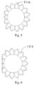
- the left coronary ostium is located in the left aortic sinus and the right coronary ostium is located in the right aortic sinus, an angle of about 120° formed between the left and right coronary ostia. Since the stent of the heart valve prosthesis 10 is uniformly and circumferentially distributed with an angle of 120°, the stent of the heart valve prosthesis 10 will not block the coronary ostia at all. As shown in Fig.
- the above-described stent includes, along its axis direction, the inflow tract, the outflow tract and the intermediate section between the inflow and outflow tracts and has the contracted configuration for delivery and the expanded configuration for deployment.
- the intermediate section In the expanded configuration of the stent, the intermediate section has an inwardly concave profile that fits the anatomy of the native valve annulus, thereby helping in positioning of the stent and providing the stent with an anchoring force.
- the outflow tract includes an annular structure and at least two protrusions formed by the axial extension, the at least two protrusions each connected to the end of the annular structure away from the intermediate section and defines vacant areas between adjacent protrusions.
- protrusions not only provide a space for suturing the leaflets in the valve assembly onto the stent, but also the defined vacant areas minimize the adverse impact on the heart's functions. Meanwhile, since the vacant areas are absent of mesh cells of stent and a skirt, which allows reducing overall filling dimension of the outflow tract after the heart valve prosthesis is loaded in a delivery system. Hence, this decreases the required size of the delivery system, thereby enabling the stent suitable for use in the replacements of multiple types of valves such as the aortic and mitral valves.
Description
- The present application relates to the field of medical instruments and, in particular, to a heart valve prosthesis and a stent thereof.
- The heart has four chambers: the left atrium and ventricle on the left side of the heart; and the right atrium and ventricle on the right side of the heart. In addition, the ventricular inflow tract is formed between the atria and the corresponding ventricle, the left ventricular outflow tract is formed between the left ventricle and aorta and the right ventricular outflow tract is formed between the right ventricle and pulmonary artery. In order to ensure the normal flow of blood in those chambers, there are also "one-way valves" in the ventricular inflow and outflow tracts. Defects in these valves can induce hemodynamic changes and functional abnormalities of heart that are called valvular heart diseases.
- With the development of social economy and the aging of population, the incidence of valvular heart diseases has increased significantly. Studies have shown that this figure has reached up to 13.3% among the aged people of 75 years or older. Surgical treatment remains the first choice for patients with severe valvular diseases. However, for those with advanced ages, complications in multiple organs, a history of thoracotomy or poor heart functions, the surgical approach is associated with high risk and high mortality or even precludes some patients. Transcatheter valve replacement/repair offers advantages such as no need for thoracotomy, minor trauma and rapid recovery. For example,
WO2015/128747 A2 discloses a system for implanting a heart valve including a radially self-expandable tubular body having an inflow end and an outflow end and a projection extending from a side surface of the tubular body toward the inflow end; a valve disposed within and attached to the tubular body; and fabric that forms a pouch between the tubular body and the projection. - The native heart valves' structure varies with their location. For this reason, valve prostheses used in interventional transcatheter valve replacement/repair procedures have to address various anatomies and pathological needs.
- The valves in the left and right ventricle inflow tracts are mitral and tricuspid, respectively, and are each an assembly including the annulus, leaflets, chordae tendineae, papillary muscles (and also including the ventricular wall in some literatures). The chordae tendineae lies between the leaflets and ventricular wall to serve as a support portion connecting the mitral (or tricuspid) leaflets and the myocardium. The anterior mitral annulus is an extension of the non-coronary and left annuli of the aortic valve. During replacement with a prosthetic valve, an inappropriate stent design tends to lead to obstructions of the left ventricular outflow tract.
- The valves in left and right ventricular outflow tracts are the aortic and pulmonary valves, respectively, which differ from those in the ventricular inflow tracts in only consisting of the leaflets and annulus. The native structures surrounding the aortic valve in the left ventricular outflow tract is complicated, and there are openings of the left and right coronary arteries on the outflow tract side of the leaflets. Therefore, an inappropriate stent design is likely to lead to fatal complications such as obstructions of the coronary artery openings.
- Among the above-described heart valves, the aortic and mitral valves are more prone to abnormalities. Since the two valves have different surrounding cardiac structures, interventional replacement of them takes different sets of factors into consideration and generally uses distinct artificial valves. For a patient who needs to replace both valves, separate delivery systems and typically separate implantation procedures are therefore required, leading to a long treatment cycle, a high patient cost, an increased intraoperative risk and a high risk of vascular damage due to the multiple establishments of implantation channels.
- On this basis, there is a need to provide a heart valve prosthesis and a stent thereof aiming at the problem that the current commercially available interventional valve prostheses are not adaptable to various valves and require separate delivery systems and separate implantation procedures.
- A stent for a heart valve prosthesis, the stent having a contracted configuration and an expanded configuration, where the stent comprises, along an axis direction of the stent, an inflow tract, an outflow tract and an intermediate section between the inflow and outflow tracts. The outflow tract comprises an annular structure and at least two protrusions each formed by extending along the axis direction of the stent. The at least two protrusions are each connected to one end of the annular structure away from the intermediate section. Vacant areas are defined between adjacent protrusions.
- The above stent includes, along its axis, the inflow tract, the outflow tract and the intermediate section between the inflow and outflow tracts, the outflow tract including the annular structure and at least two protrusions formed by extending along the axis direction of the stent. Each protrusion is connected to one end of the annular structure away from the intermediate section and a vacant area is defined between adjacent protrusions. The protrusions not only contribute to providing a space for suturing leaflets in a valve assembly onto the stent, but the vacant area defined by the protrusions is able to minimize the adverse impact on the heart's functions. Moreover, the vacant areas are absent of stent mesh cells and a skirt, which allows reducing overall filling dimension of the outflow tract after the heart valve prosthesis is loaded in a delivery system. Hence, this decreases the required size of the delivery system, thereby enabling the stent suitable for use in the replacements of multiple types of valves such as the aortic and mitral valves, while not requiring multiple delivery systems or multiple implantation procedures.
- In one embodiment, three protrusions are provided and the three protrusions are distributed uniformly around a circumference of the annular structure.
- In one embodiment, the outflow tract further comprises suture rods connected to one end of a corresponding protrusion away from the intermediate section.
- In one embodiment, each of the at least two protrusions has a triangular structure comprising one or more structural cells, which are arranged into one or more rows.
- In one embodiment, each of the at least two protrusions is rod-shaped.
- In one embodiment, the intermediate section has an inwardly concave profile when the stent is in the expanded configuration.
- According to the invention, each of the at least two protrusions has a stiffness gradually descending along a direction from the intermediate section to the outflow tract.
- In one embodiment, the stent further comprises barbs circumferentially distributed on the intermediate section and/or the outflow tract, the barbs extending outwardly from the intermediate section or the outflow tract.
- In one embodiment, the outflow tract has an axial height of 5-30mm.
- In one embodiment, in the expanded configuration, the intermediate section has a minimum diameter not greater than a minimum diameter of the inflow tract and a maximum diameter not greater than a maximum diameter of the outflow tract.
- In one embodiment, the stent further comprises lugs arranged on one end of the inflow tract away from the intermediate section and/or one end of the outflow tract away from the intermediate section.
- A heart valve prosthesis comprises a valve assembly and the stent as defined above, in which the valve assembly is attached to the stent.
- The above heart valve prosthesis is adaptable to multiple valves and the corresponding interventional valve replacement.
-
-
Fig. 1 is a structural schematic diagram of a stent of a first embodiment that has been used in a heart valve prosthesis. -
Fig. 2 is a structural schematic diagram of the stent ofFig. 1 . -
Fig. 3 is a structural schematic diagram of the stent ofFig. 1 used to replace a native mitral value. -
Fig. 4 is a structural schematic diagram of the stent ofFig. 1 used to replace a native aortic value. -
Fig. 5 is a structural schematic diagram of an embodiment of an inflow tract ofFig. 1 . -
Fig. 6 is a structural schematic diagram of another embodiment of the inflow tract ofFig. 1 . -
Fig. 7 is a top view of the stent ofFig. 1 . -
Fig. 8 is a structural schematic diagram of a stent according to a second embodiment. -
Fig. 9 is a structural schematic diagram of a stent according to a third embodiment. -
Fig. 10 is a structural schematic diagram of a stent according to a forth embodiment. -
Fig. 11 is a structural schematic diagram of an embodiment of a heart valve prosthesis during a diastolic phase of the heart, when replacing the native mitral valve. -
Fig. 12 is a structural schematic diagram of the heart valve prosthesis ofFig. 11 during a systolic phase of the heart, when replacing the native mitral valve. -
Fig. 13 is a structural schematic diagram of the heart valve prosthesis ofFig. 11 during a systolic phase of the heart, when replacing the native aortic valve. -
Fig. 14 is a structural schematic diagram of the heart valve prosthesis ofFig. 11 during a diastolic phase of the heart, when replacing the native aortic valve. - As mentioned in the Background, present application provides a heart valve prosthesis and a stent thereof aiming at the problem that the current commercially available interventional valve prostheses are not adaptable to various valves and thus require separate delivery systems and separate implantation procedures.
- After further researches, according to the invention, in one embodiment, there is provided a stent for a heart valve prosthesis. The stent is configured to support an artificial heart valve. The stent comprises, along an axis direction of the stent, an inflow tract, an outflow tract and an intermediate section between the inflow and outflow tracts. The stent has a contracted configuration and an expanded configuration. The outflow tract includes an annular structure and at least two protrusions formed by extending along the axis direction of the stent. The at least two protrusions are each connected to one end of the annular structure away from the intermediate section and define vacant areas between adjacent protrusions. Each protrusion has a stiffness gradually descending along a direction from the intermediate section to the outflow tract.
- Further, On the basis of the above stent, there is also provided a heart valve prosthesis for replacing a native heart valve.
- Specific embodiments of present application will be described in detail below in conjunction with the accompany drawings to make the above objects, features and advantages of the present application more apparent and readily understood.
- As shown in
Fig. 1 andFig. 2 , astent 100 for aheart valve prosthesis 10 according to embodiment 1 includes, along an axis thereof, aninflow tract 110, anoutflow tract 120 and anintermediate section 130. Thestent 100 has a contracted configuration for delivery and an expanded configuration for deployment. Thestent 100 is configured to support an artificial heart valve (that is, a valve assembly 11), and constitutes saidheart valve prosthesis 10 together with thevalve assembly 11. Theintermediate section 130 is disposed between theinflow tract 110 and theoutflow tract 120. Depending on the flow direction of blood, theoutflow tract 120 is disposed downstream of theinflow tract 110. - In one embodiment, the
stent 100 may be a self-expandable stent including a plurality of structural cells, which are interconnected to form a mesh. Thestent 100 is fabricated from a biocompatible material such as a titanium alloy or a nickel-titanium alloy. It is noted that the structural cells refer to mesh cells made of a biocompatible material such as a titanium alloy or a nickel-titanium alloy and in the shape of diamonds, pentagons, triangles, teardrops or the like. The structural cells include first structural cells configured to form theoutflow tract 120, second structural cells configured to form theinflow tract 110 and third structural cells configured to form theintermediate section 130. In other embodiments, thestent 100 may be a balloon-expandable stent including a plurality of structural cells in a mesh form. - As shown in
Fig. 2 , theoutflow tract 120 has a mesh structure consisting of one or more rows of first structural cells. The plurality of first structural cells interconnect along a circumference of thestent 100 to form a row, and multiple rows of first structural cells interconnect along an axis direction of thestent 100. The first structural cells may be in the shape of diamonds, pentagons, triangles, teardrops or other closed loops. In this embodiment, the first structural cells may be diamonds. It should be noted that the number of mesh loops may depend on an actually needed axial height of theoutflow tract 120. - When the
stent 100 is released, theoutflow tract 120 is located on a hemodynamic outflow side of the native valve. In one embodiment, theoutflow tract 120 in thestent 100 may have an axial height of 5-30 mm. - Referring again to
Fig. 2 , theoutflow tract 120 may be a spherical structure. That is, theoutflow tract 120 extends from its end connected to theintermediate section 130 away from theintermediate section 130 by a certain radius, i.e., radially outward from a center axis of thestent 100. - It should be noted that, in other embodiments, the
outflow tract 120 may be in the shape of a truncated cone. That is, the end of theoutflow tract 120 proximal to theintermediate section 130 has a diameter greater than the end of theoutflow tract 120 distal from theintermediate section 130. That is, the diameter of theoutflow tract 120 decreases gradually in a direction extending axially away from theintermediate section 130. - The
outflow tract 120 includes theannular structure 121 andprotrusions 122 formed by extending along the axial direction. The number of the protrusions may be two or more. Each of theprotrusions 122 is connected to the end of theannular structure 121 away from theintermediate section 130, and thevacant areas 123 are defined betweenadjacent protrusions 122. Thesevacant areas 123 can minimize any adverse influence on the heart's functions. Moreover, the vacant areas are absent of stent mesh cells (structural cells) and a skirt, which allows to reduce overall filling dimension of the outflow tract after theheart valve prosthesis 10 is loaded into a delivery system, thus reducing a required footprint of the delivery system and making the stent suitable for use in the replacements of multiple types of valves, such as the aortic and mitral valves. In addition, theprotrusions 122 contribute to providing a space for suturing leaflets in the valve assembly onto thestent 100, so that the sutured leaflets are not affected by the surrounding tissue. - One end of the
annular structure 121 in theoutflow tract 120 is connected to the end of theintermediate section 130 away from theinflow tract 110, while the other end of theannular structure 121 is connected to aprotrusion 122. As noted above, theoutflow tract 120 may be implemented as a mesh structure composed of one or more rows of first structural cells. As shown inFig. 2 , the first structural cell includes a firstsub-structural cell 1211 and a secondsub-structural cell 1221. In this case, theannular structure 121 is constructed by the one or more rows of firstsub-structural cells 1211 that are sequentially connected along the circumferential direction. Theannular structure 121 provides sufficient support for the outflow tract of thestent 100 and sufficient counter-traction for the leaflets. In one embodiment, theoutflow tract 120 has a maximum diameter of 21-56 mm. - In one embodiment, the number of the
protrusions 122 is three, and the threeprotrusions 122 are uniformly distributed along the circumferential direction of theannular structure 121. That is, the threeprotrusions 122 are uniformly distributed with a circumferential angle of 120°. Since the coronary sinus ostium in the aortic valve has a distribution of about 120° and the anterior mitral annulus accounts for one third of the annulus perimeter, by providing threeprotrusions 122, thestent 100 can be used for both aortic and mitral valves. In this way, for patients in need of replacing both valves, only one suitable delivery system is required to achieve replacements of two valves through a same implantation channel, and there is no need to implant different valve prostheses in two separate implantation procedures, which allow to save treatment time and costs and reduce risk of vascular damages incurred by the multiple establishments of implantation channels. It should be noted that, since the tricuspid valve is anatomically similar to the mitral valve, the stent can also be used for tricuspid valve replacement. In one embodiment, as shown inFig. 2 , theoutflow tract 120 may also includesuture rods 124, the suture rod connected to one end of arespective protrusion 122 away from theintermediate section 130 and configured to attach the leaflets. It should be noted that holes may be formed in thesuture rod 124, through which the leaflets in the valve assembly can be sutured onto thestent 100. Alternatively, the leaflets may be attached to thesuture rods 124 using an adhesive. The present application is not limited to any particular method for attaching the leaflets to thesuture rods 124. - In one embodiment according to the invention, in the direction from the
intermediate section 130 to theoutflow tract 120, eachprotrusion 122 has a stiffness gradually descending in order to accommodate varying traction forces at different locations of the stent applied by the leaflets in theheart valve prosthesis 10, thus helping in extending the stent's serve life. As shown inFig. 11 , the end of a leaflet of the heart valve prosthesis attached to both theintermediate section 130 andoutflow tract 120 is the attachment end and the other end of the leaflet of the heart valve prosthesis not connected to the stent is the free end. The inventors have found from researches that, during opening of the leaflets in theheart valve prosthesis 10 under the action of blood flow, the aligned leaflets will be increasingly separated apart from one another radially while gradually moving axially away from theintermediate section 130 in the blood flow direction, until the aligned leaflets are fully opened, where the free end of each leaflet is farthest away from the stent's center axis. On the other hand, as shown inFig. 12 , the leaflets of theheart valve prosthesis 10 are subjected to a pressure towards theinflow tract 110 of the stent due to the back-pressure of blood, which causes the leaflets of theheart valve prosthesis 10 to move radially towards the center axis of the stent and move axially towardsinflow tract 110 of the stent. When leaflets of theheart valve prosthesis 10 are fully closed, free ends of multiple adjacent leaflets closely fit each other while axial displacements of their free ends towards theinflow tract 110 of the stent are occurred. - As a bearing member of the leaflets of the
heart valve prosthesis 10 during the movements, thestent 100 reciprocates circumferentially and axially with the opening and closing of the leaflets of theheart valve prosthesis 10. That is to say, the closing of the leaflets of theheart valve prosthesis 10 causesprotrusions 122 of thestent 100 to deform radially towards the center axis of the stent and to deform axially towards theintermediate section 130 of thestent 100, in order to resist the pressure of blood. On the other hand, while the leaflets are open,protrusions 122 of thestent 100 gradually recover their normal shapes due to the shape memory nature of thestent 100. Due to the inherent design characteristics of the leaflets of theheart valve prosthesis 10, from the free end to the attachment end, the area of each leaflet of theheart valve prosthesis 10 subjected to the back-pressure of blood in the axial direction gradually decreases, and hence the back-pressure of blood applied to each leaflet gradually decreases due to the constant blood pressure. As a result, the tractions of the leaflets applied to respective locations of thestent 100 substantially present a trend of axially ascending gradually from theintermediate section 130 to theoutflow tract 120, and thus theprotrusion 122, along the said direction, should have a stiffness decreasing gradually and a flexibility ascending gradually. In this way, when the leaflets are closed, the stiffer portions of thestent 100 serve as portions of thestent 100 providing higher deformation resistances, while the less stiff portions of thestent 100 serve as portions of thestent 100 having large deformations with the deformation of the leaflets. Thus, theprotrusions 122 of thestent 100 have a reduced risk of fracture and an extended fatigue lifetime. - In the case that the
outflow tract 120 is implemented as a spherical structure, theannular structure 121 is provided at a proximal end of the spherical structure, while thesuture rods 124 are provided at a distal end of the spherical structure. It should be noted that the proximal and distal ends are mentioned here with respect to the direction of blood flow, which flows from the proximal end towards the distal end. - Referring again to
Fig. 2 , in one embodiment, theprotrusion 122 is formed by one or more rows of the secondsub-structural cells 1221. The largevacant areas 123 absent of any aforementioned structural cell is defined betweenprotrusions 122. In this embodiment, oneprotrusion 122 is a triangular structure extending away from theintermediate section 130 and composed of one secondsub-structural cell 1221. It should be noted that the secondsub-structural cells 1221 may assume either the same shape as or a different shape from the firstsub-structural cells 1211. - In one embodiment, any of the
protrusions 122 may be a part of a sphere, a cone or a cylinder, and may be a planar triangle or any other shape, as long as it extends from theannular structure 121 along the direction away from theintermediate section 130. Further, all of theprotrusions 122 may be of the same shape and size. It should be noted that each of theprotrusions 122 may be of a different shape and size. It is also possible that some of them are of the same shape and size but some of them have different shapes and sizes from the others. - Referring again to
Fig. 1 andFig .2 , in one embodiment, theinflow tract 110 includes mesh structures composed of one or more rows of secondstructural cells 1111. Theinflow tract 110 is fabricated from a shape memory and biocompatible tube by cutting, for example, the cold laser cutting. It should be noted that theintermediate section 130 andoutflow tract 120 can be fabricated by a same cutting method. In addition, theinflow tract 110,outflow tract 120 andintermediate section 130 may be integrally formed. It should be noted that the secondstructural cells 1111 of theinflow tract 110 may be mesh cells that can form closed shapes, such as diamonds, pentagons, triangles, teardrops or the like, or may be rods. In addition, theinflow tract 110 may be formed by weaving with filaments. In one embodiment, the weaving filaments may be woven into a sinusoidal or zigzag pattern. - When the
stent 100 is used for the aortic and mitral valves and after release of thestent 100, theinflow tract 110 is located at a hemodynamic inflow side of the native valve and fits tissues around the annulus of the native valve. Specifically, as shown inFig. 3 , when theheart valve prosthesis 10 using thestent 100 is used to replace the native mitral valve, theinflow tract 110 covers the left atrioventricular ostium. When theheart valve prosthesis 10 using thestent 100 is used to replace the native aortic valve, theinflow tract 110 covers the base of the aortic sinus, as shown inFig. 4 . - In one embodiment, the shaped of the radial cross-section of the
inflow tract 110 may be annulus, D-shaped or flower-shaped or other irregular shape. In order to ensure the inflow of blood, from the end of theinflow tract 110 connected to theintermediate section 130, theinflow tract 110 extends axially away from theintermediate section 130. In other words, the attachment end of theinflow tract 110 to theintermediate section 130 extends outward away from theintermediate section 130 along the axial direction. In another embodiment, from the end of theinflow tract 110 connected to theintermediate section 130, theinflow tract 110 both axially and radially extends away from theintermediate section 130. In still other embodiments, from the end of theinflow tract 110 connected to theintermediate section 130, theinflow tract 110 only radially extends away from theintermediate section 130. - Further, in order to prevent dislodgement of the heart valve prosthesis of the
stent 100, theinflow tract 110 has a minimum diameter greater than the native valve annulus. In one embodiment, the minimum diameter of theinflow tract 110 ranges from 25 mm to 65 mm. - As shown in
Fig. 1 , theinflow tract 110 may extend from the connection connected to theintermediate section 130 by an axial height H of 0-20 mm away from theintermediate section 130. Here, when the height H is equal to 0 mm, theinflow tract 110 of thestent 100 only radially extends away from its connection connected to the intermediate section. That is, all structural cells in theinflow tract 110 lie in the same plane. - In one embodiment where the
inflow tract 110 has a D-shaped radial cross-section, theinflow tract 110 includes a plurality of firstconstituent cells 111a, the plurality of firstconstituent cells 111a having different mesh sizes, so that formedinflow tract 110 has a varying diameter along varying directions of its radial cross-section, as shown inFig. 5 . In other embodiments, as shown inFig. 6 , theinflow tract 110 includes a plurality of equally-sized secondconstituent cells 111b, the plurality of secondconstituent cells 111b having a same mesh size. In this case, some secondconstituent cells 111b have their axial length longer than the remaining secondconstituent cells 111b, so that formedinflow tract 110 has a varying diameter along varying directions of its radial cross-section. It should be noted that the first and secondconstituent cells inflow tract 110. - Specifically, when the
heart valve prosthesis 10 incorporating thestent 100 is used to replace the native aortic valve, the flat portion of the D-shaped inflow tract can be brought into close contact with the left coronary sinus of the native aortic valve, greatly reducing the risk of left bundle branch block around the left coronary sinus caused by thestent 100. Likewise, when theheart valve prosthesis 10 incorporating thestent 100 is used to replace the native mitral valve, the flat portion of the D-shaped inflow tract can be brought into close contact with the native aortic valve, thus avoiding theheart valve prosthesis 10 from impairing the functions of the native aortic valve and reducing the risk of obstruction of the left ventricular outflow tract. - In case of the
inflow tract 110 having a radial cross-section that is annular, as shown inFig. 2 , theinflow tract 110 includes a plurality of equally-sized secondstructural cells 1111 having the same axial height H, so that theinflow tract 110 has a constant radial diameter. That is, theinflow tract 110 is a cylindrical structure. In this case, the cross-sectionallyannular inflow tract 110 extends radially away from theintermediate section 130 and axially away from theoutflow tract 120. In this way, theinflow tract 110 is prevented from damaging the heart tissue due to an excessive radial dimension. - Specifically, when the
heart valve prosthesis 10 is used to replace the native aortic valve, theinflow tract 110 covers the base of the aortic sinus while extending towards the left ventricle. When theheart valve prosthesis 10 is used to replace the native mitral valve, theinflow tract 110 covers the atrioventricular orifice while extending towards the left atrium. - In an alternative embodiment, the
inflow tract 110 may be a spherical structure. That is to say, as the height of theinflow tract 110 axially extending away from thetransition area 130 increases, the diameter of the radial cross-section of theinflow tract 110 gradually increases and then gradually decreases. It should be noted that theinflow tract 110 may also be in the shape of a truncated cone with a gradually increasing diameter as theinflow tract 110 axially extends away from its connection connected to theintermediate section 130. - In this embodiment, the
stent 100 has a contracted configuration for delivery and an expanded configuration for deployment. In the expanded configuration, theintermediate section 130 has an inwardly concave profile fitting with the native annulus. This can help in positioning of thestent 100 and providing thestent 100 with an anchoring force. Accordingly, in one embodiment, theintermediate section 130 has a minimum diameter not greater than the minimum diameter of theinflow tract 110 and a maximum diameter not greater than the maximum diameter of theoutflow tract 120, so that thestent 100 is inwardly concave at theintermediate section 130 on the whole. After release of thestent 100, theintermediate section 130 fits the native annulus to providestent 100 with radial support. The inwardly concave structure not only helps in positioning of theheart valve prosthesis 10 but also decreases axial movement or displacement of thestent 100 to a certain extent. - Referring to
Fig. 2 , theintermediate section 130 has a mesh structure including one or more rows of thirdstructural cells 1311. In one embodiment, the thirdstructural cells 1311 in theintermediate section 130 may be in the shape of diamonds. It should be noted that the application is not limited to any particular shape of the thirdstructural cells 1311 in theintermediate section 130, and the structural cells may also have a triangular or any other suitable shape. In one embodiment, theintermediate section 130 may have an axial height of 3-15 mm. - In one embodiment, the
intermediate section 130 may be stiffer than both theinflow tract 110 and theoutflow tract 120 in order to further provide radial support to thestent 100. It should be noted that the stiffness of material of theintermediate section 130 is higher than that of material of both theinflow tract 110 andoutflow tract 120 to offer the intermediate section 130 a greater stiffness, or the more compact structure of theintermediate section 130 offers itself a greater stiffness. - The
intermediate section 130 fits the native annulus after release of thestent 100. Therefore, the minimum diameter of theintermediate section 130 is greater than the diameter of the native annulus. In one embodiment, the minimum diameter of theintermediate section 130 ranges from 20 mm to 58 mm. - It should be noted that the first structural cells, second
structural cells 1111 and third structural cells 131 may be either of the same shape or of different shapes, which can be determined depending on the actual needs. - For patients with valve stenosis, the
stent 100 of theheart valve prosthesis 10 could be anchored with the aid of the radial support provided by the inwardly concave structure formed at theintermediate section 130. For regurgitation patients, theheart valve prosthesis 10 is design to unilateral passive open in the blood flow direction and unilateral passive close against the blood flow direction. In this design, blood constantly pushes against the leaflets in theheart valve prosthesis 10 during closing of the leaflets, thus avoiding axial displacement of theheart valve prosthesis 10 over time due to insufficient anchoring force. - Accordingly, in one embodiment, as shown in
Figs. 1 and2 , thestent 100 may further includebarbs 140 projecting outwardly from theintermediate section 130 or from theoutflow tract 120. That is to say,barbs 140 extend radially along the direction away from thestent 100. Thebarbs 140 may be distributed circumferentially across both theintermediate section 130 and theoutflow tract 120. In this case,barbs 140 can be arranged into one or more rows. It should be noted that, in case of thebarbs 140 distributed on theoutflow tract 120, they can be distributed on theannular structure 121 of theoutflow tract 120, which can further provide theannular structure 121 with an anchoring force. In other embodiments, thebarbs 140 may be circumferentially distributed only on theintermediate section 130. Alternatively, thebarbs 140 may be circumferentially distributed only on theoutflow tract 120. - The
barbs 140 outwardly projecting from thestent 100 so as to pierce the native valve's leaflets and annulus, providing an anchoring force to theheart valve prosthesis 10. In this way, thebarbs 140 and inwardly concave profile together provide the anchoring force to thestent 100 to avoid movement or displacement of thestent 100. Further, due to the anchoring force provided by thebarbs 140, anchoring support required by thestent 100 at the native annulus can be reduced, thus avoiding rupture of the native annulus. - Specifically, as shown in
Fig. 7 , eachbarb 140 may have a proximal end connected to a node of the mesh structure of theintermediate section 130 oroutflow tract 120 and a distal end having a triangular, a tapered shape or other shape that can facilitate to pierce tissues. - In one embodiment, each
barb 140 extends both radially and axially with respect to theintermediate section 130 oroutflow tract 120. That is, eachbarb 140 extends away from theintermediate section 130 oroutflow tract 120 at an angle with respect to theintermediate section 130 oroutflow tract 120. In one embodiment, eachbarb 140 forms an angle of 20-160° with a normal of an outer surface of theintermediate section 130 oroutflow tract 120 at a node of the stent. Here, the "stent node" refers to a junction of thebarb 140 with the outer surface of theintermediate section 130 oroutflow tract 120. Alternatively, thebarb 140 may extend radially away from the node. - Further, in one embodiment, the
barbs 140 may extend away from theintermediate section 130 oroutflow tract 120 along the radial direction of theintermediate section 130 oroutflow tract 120 and extend axially towards theinflow tract 110. Specifically, with thebarbs 140 distributed on theintermediate section 130 as an example, thebarbs 140 each form an angle with the outer surface of theintermediate section 130 and have an end portion pointing toward theinflow tract 110. Likewise, thebarbs 140 may be distributed on theoutflow tract 120 in the same manner. - It should be noted that each
barb 140 may consist of two portions connected to each other. One of two portions may extend in a manner in consistent with radial extension of theintermediate section 130 and have a square or trapezoid cross-sectional shape, while the other portion may have a curved cross-sectional shape. In one embodiment, the center of the curved cross-section is located at the side where theinflow tract 110 is situated. - Alternatively, the
barb 240 having a configuration of two portions may have a configuration of a combination of an arc portion and a straight portion. In this case, the arcuate portion is connected to theintermediate section 130 oroutflow tract 120 at one end and to the straight portion at the other end, and the straight portion is tangential to the arcuate portion. - As shown in
Fig. 2 , in one embodiment, the cross section of thebarb structure 140 in the radial direction may also be a curved surface that extending from the junction of thebarb 140 with theintermediate section 130 oroutflow tract 120. It should be noted that eachbarb 140 may having a configuration of a combination of multiple curved segments. - In one embodiment, the
barb 140 extends a radial length of 0.5-6 millimeters (mm) away from theintermediate section 130 oroutflow tract 120. That is, when thebarb 140 is arranged on theintermediate section 130, there may be a perpendicular distance of 0.5-6 mm from the end of thebarb 140 away from theintermediate section 130 to the end of thebarb 140 connected to theintermediate section 130. Similarly, when thebarb 140 is arranged on theoutflow tract 120, there may also be a perpendicular distance of 0.5-6 mm from the end of thebarb 140 away from theoutflow tract 120 to the end of thebarb 140 connected to theoutflow tract 120. - In one embodiment, the
barbs 140 and theoutflow tract 120 are integrally formed. Alternatively, thebarbs 140 and theintermediate section 130 may be integrally formed. Alternatively, thebarbs 140,intermediate section 130 andoutflow tract 120 may be integrally formed. It should be noted that such integral formation can be achieved by a cutting technique. In other embodiments, thebarbs 140 may be fixedly coupled to theoutflow tract 120, for example, by welding, riveting, or the like. Likewise, thebarbs 140 may be alternatively fixed to theintermediate section 130 by welding or riveting or otherwise. - In one embodiment, the
stent 100 further includeslugs 150 for fitting theheart valve prosthesis 10 with a delivery system for delivering theheart valve prosthesis 10. Thelugs 150 are attached to the delivery system to ensure a constant relative position between theheart valve prosthesis 10 and the delivery system in the courses of theheart valve prosthesis 10 being loaded within the delivery system, released from the delivery system and delivered by the delivery system within the body. Depending on the implantation method of theheart valve prosthesis 10 and the function of the delivery system, thelugs 150 may be arranged at the end of theinflow tract 110 away from theintermediate section 130, or arranged at the end of theoutflow tract 120 away from theintermediate section 130. Still, thelugs 150 may also be arranged at the end of theinflow tract 110 away from theintermediate section 130, and the end of theoutflow tract 120 away from theintermediate section 130. The number and locations of thelugs 150 may be determined depending on the actual needs. - The
lugs 150 are the final portions of theheart valve prosthesis 10 detached from the delivery system. Specifically, in the case that thelugs 150 are arranged at the end of theinflow tract 110 away from theintermediate section 130, theoutflow tract 120 will be released first during the release. In the case that thelugs 150 are arranged on the end of theoutflow tract 120 away from theintermediate section 130, theinflow tract 110 will be released first during the release. In the case that thelugs 150 are arranged at both the end of theinflow tract 110 away from theintermediate section 130 and the end of theoutflow tract 120 away from theintermediate section 130, the release process is a two-way release process which can be performed by release thelugs 150 on either end first or release thelugs 150 on both ends at the same time finally. - As shown in
Fig. 8 , astent 200 according to a second embodiment includes aninflow tract 210, anoutflow tract 220, anintermediate section 230,barbs 240 and lugs 250. The structures of these components in thestent 200, as well as the connections therebetween and the like, are the same as those in the first embodiment and will not be again described here. Thestent 200 differs from thestent 100 according to the first embodiment in that theoutflow tract 220 is cylindrical. That is, theoutflow tract 220 extends axially from its end connected to theintermediate section 230 away from theintermediate section 230 with a constant diameter. - As shown in
Fig. 9 , astent 300 according to a third embodiment includes aninflow tract 310, anoutflow tract 320, anintermediate section 330,barbs 340 and lugs 350. The structures of these components in thestent 300, as well as the connections therebetween and the like, are the same as those in the first embodiment and will not be again described here. Thestent 300 differs from thestent 100 according to the first embodiment in that eachprotrusion 322 has a triangular structure extending away from theintermediate section 330. The triangular structure includes a plurality of second sub-structural cells, each implemented as a mesh cell. The plurality of second sub-structural cells are arranged into multiple rows. In this embodiment, three second sub-structural structural cells are provided and arranged into two rows. Referring again toFig. 9 , the three second sub-structural cells are afirst cell 3221a, asecond cell 3221b and athird cell 3221c. The first andsecond cells annular structure 321. One end of thethird cell 3221c is connected to the ends of the first andsecond cells annular structure 321. The other end of thethird cell 3221c away from theannular structure 321 is connected to asuture post 324. It should be noted that the multiple cells may be arranged in to a single row. In other embodiments, the multiple cells may be arranged into three or more rows. In addition, the number of the second sub-structural cells may be two, four or more, which is not limited here. - As shown in
Fig. 10 , astent 400 according to a fourth embodiment includes aninflow tract 410, anoutflow tract 420, anintermediate section 430,barbs 440 and lugs 450. The structures of these components in thestent 400, as well as the connections therebetween and the like, are the same as those in the first embodiment and will not be again described here. Thestent 400 differs from thestent 100 according to the first embodiment in that eachprotrusion 422 is rod-shaped structure. One end of theprotrusion 422 is connected to the end of theannular structure 421 away from theintermediate section 430, and the other end of theprotrusion 422 away from theannular structure 421 is connected to asuture post 424. It should be noted that eachprotrusion 422 may also include a plurality of second sub-structural cells, each implemented as rod-shaped structure and connected sequentially. - As shown in
Fig. 1 , theheart valve prosthesis 10 according to an embodiment includes avalve assembly 11 and the stent according to any of the above embodiments, thevalve assembly 11 attached to the inside of the stent. Specifically, thevalve assembly 11 may include leaflets and a skirt. The leaflets are attached to both the intermediate section and the outflow tract, with the skirt being attached to the inflow tract, intermediate section and the outflow tract, in order to ensure the single blood flow channel and prevent perivalvular leakage. - Since the outflow tract includes protrusions and vacant areas and has leaflets sutured at its inner side, the radial diameter of the stent decreases and the axial height of the stent increases after the
heart valve prosthesis 10 is loaded into the delivery system. Moreover, since the vacant areas are absent of mesh cells of the stent and a skirt, the space is saved and the diameter of outflow tract in the contracted configuration of theheart valve prosthesis 10 is reduced, thereby reducing the required diameter of the delivery system and risk of vascular damage during delivery. - Since the
heart valve prosthesis 10 is suitable for use in the replacement of both the aortic and mitral valves, it is possible that such prosthesis may be used to replace the aortic or mitral valve separately, or two such prostheses may be used to successively replace valves in two locations through two times of successive loading of the two prostheses into a same delivery system and two times of successive delivering of the two prostheses in a single implantation channel, thus shortening the time and incisions required by channel establishment, lowering the risk of injury to the patient and bringing down the cost of surgery. It is also possible that two such prostheses may be used to successively replace valves in two locations through one time of delivering of the two prostheses using one delivery system. In this case, twoheart valve prostheses 10 are loaded into the delivery system at the same time, and are replaced one by one. This can additionally shorten the surgical time and lower the risk of vascular damage during delivery. - Specifically, when the
heart valve prosthesis 10 is used to replace a native mitral valve, the vacant areas correspond to the anterior leaflet side of the native mitral valve. As shown inFig. 11 , during a diastolic phase of the heart, the leaflets of theheart valve prosthesis 10 are opened naturally by the blood wash. During a systolic phase of the heart, blood flows from the ventricle to the aorta. At this time, the aortic valve is opened and theheart valve prosthesis 10 that replaces the native mitral is closed, as shown inFig. 12 . The path of blood flowing out of the left ventricle is called the left ventricular outflow tract, and the anterior leaflet side of the native value faces this left ventricular outflow tract. When the stent in theheart valve prosthesis 10 that replaces the native mitral valve has a low height at its subvalvular portion facing the left ventricular outflow tract, it can prevent the left ventricular outflow tract from being blocked to cause malfunction of the heart. There are vacant areas defined in the outflow tract of the stent in theheart valve prosthesis 10, so that when the vacant areas face the anterior leaflet side of the native valve, the height of the subvalvular portion of the stent facing the left ventricular outflow tract is low. This allows preventing obstruction of the left ventricular outflow tract due to an excessive subvalvular length of the stent on the premise of an ensured normal operation of theheart valve prosthesis 10. It should be noted that the arrows inFig. 11 and Fig. 12 indicate the direction of blood flow. - When the
heart valve prosthesis 10 is used to replace the native aortic valve, the vacant areas correspond to the coronary sinus ostia. During the heart beating, the left coronary ostium is located in the left aortic sinus and the right coronary ostium is located in the right aortic sinus, an angle of about 120° formed between the left and right coronary ostia. Since the stent of theheart valve prosthesis 10 is uniformly and circumferentially distributed with an angle of 120°, the stent of theheart valve prosthesis 10 will not block the coronary ostia at all. As shown inFig. 13 , when the heart contracts, the leaflets of theheart valve prosthesis 10 will be opened naturally by the blood wash, and the blood flows from the left atrium into the ascending aorta. During a diastolic phase of the heart, since the blood pressure in the aorta will be higher than that in the ventricle, the leaflets close under the blood pressure while blood enters into the coronary artery via the coronary ostia, as shown inFig. 14 . It should be noted that the arrows inFig. 13 and Fig. 14 indicate the direction of blood flow. - The above-described stent includes, along its axis direction, the inflow tract, the outflow tract and the intermediate section between the inflow and outflow tracts and has the contracted configuration for delivery and the expanded configuration for deployment. In the expanded configuration of the stent, the intermediate section has an inwardly concave profile that fits the anatomy of the native valve annulus, thereby helping in positioning of the stent and providing the stent with an anchoring force. The outflow tract includes an annular structure and at least two protrusions formed by the axial extension, the at least two protrusions each connected to the end of the annular structure away from the intermediate section and defines vacant areas between adjacent protrusions. These protrusions not only provide a space for suturing the leaflets in the valve assembly onto the stent, but also the defined vacant areas minimize the adverse impact on the heart's functions. Meanwhile, since the vacant areas are absent of mesh cells of stent and a skirt, which allows reducing overall filling dimension of the outflow tract after the heart valve prosthesis is loaded in a delivery system. Hence, this decreases the required size of the delivery system, thereby enabling the stent suitable for use in the replacements of multiple types of valves such as the aortic and mitral valves.
- The features of the above-described embodiments may be combined arbitrarily. While not all possible combinations of these features are described for the sake of brevity, they are all considered within the scope of this specification as long as there is no contradiction therein.
- The foregoing embodiments represent merely a few embodiments of the present application, and have been described above specifically and in detail. However, they are not intended to be understood as limiting the scope of the application. It is noted that, many variations and modifications can be made by those of ordinary skill in the art without departing from the protection scope of the application as defined by the appended claims.
Claims (11)
- A stent (100,200,300,400) for a heart valve prosthesis (10), the stent (100,200,300,400) having a contracted configuration and an expanded configuration, characterized in that, the stent (100,200,300,400) comprises, along an axis direction of the stent (100,200,300,400), an inflow tract (110,210,310,410), an outflow tract (120,220,320,420) and an intermediate section (130,230,330,430) between the inflow tract and outflow tract, the outflow tract (120,220,320,420) comprising an annular structure (121,321,421) and at least two protrusions (122,322,422) each formed by extending along the axis direction of the stent (100,200,300,400), the at least two protrusions (122,322,422) each connected to one end of the annular structure (121,321,421) away from the intermediate section (130,230,330,430), wherein a vacant area (123) is defined between adjacent protrusions (122,322,422),
wherein each protrusion (122,322,422) has a stiffness gradually descending along a direction from the intermediate section (130,230,330,430) to the outflow tract (120,220,320,420). - The stent (100,200,300,400) of claim 1, wherein three protrusions (122,322,422) are provided, the three protrusions (122,322,422) distributed uniformly around a circumference of the annular structure (121,321,421).
- The stent (100,200,300,400) of claim 1 or 2, wherein the outflow tract (120,220,320,420) further comprises a suture rod (124) connected to one end of each protrusion (122,322,422) away from the intermediate section (130,230,330,430).
- The stent (100,200,300,400) of claim 1 or 2, wherein each protrusion (122,322,422) has a triangular structure comprising one or more structural cells, which are arranged into one or more rows.
- The stent (100,200,300,400) of claim 1 or 2, wherein each protrusion (122,322,422) is rod-shaped.
- The stent (100,200,300,400) of claim 1 or 2, wherein the intermediate section (130,230,330,430) has an inwardly concave profile when the stent (100,200,300,400) is in the expanded configuration.
- The stent (100,200,300,400) of claim 1 or 2, further comprising barbs (140,240,340,440) circumferentially distributed on the intermediate section (130,230,330,430) and/or the outflow tract (120,220,320,420), the barbs (140,240,340,440) formed by extending outwardly from the intermediate section (130,230,330,430) or the outflow tract (120,220,320,420).
- The stent (100,200,300,400) of claim 1 or 2, wherein the outflow tract (120,220,320,420) has an axial height of 5-30mm.
- The stent (100,200,300,400) of claim 1 or 2, wherein in the expanded configuration, the intermediate section (130,230,330,430) has a minimum diameter not greater than a minimum diameter of the inflow tract (110,210,310,410) and a maximum diameter not greater than a maximum diameter of the outflow tract (120,220,320,420).
- The stent (100,200,300,400) of claim 1 or 2, further comprising lugs (150,250,350,450) arranged on one end of the inflow tract (110,210,310,410) away from the intermediate section (130,230,330,430) and/or one end of the outflow tract (120,220,320,420) away from the intermediate section (130,230,330,430).
- A heart valve prosthesis (10), characterized in that, comprising a valve assembly and a stent (100,200,300,400) as defined in any of claims 1 to 10, the valve assembly attached to the stent (100,200,300,400).
Applications Claiming Priority (2)
| Application Number | Priority Date | Filing Date | Title |
|---|---|---|---|
| CN201711467178.7A CN109966023A (en) | 2017-12-28 | 2017-12-28 | Heart valve prosthesis and its bracket |
| PCT/CN2018/117163 WO2019128583A1 (en) | 2017-12-28 | 2018-11-23 | Cardiac valve prosthesis and stent thereof |
Publications (3)
| Publication Number | Publication Date |
|---|---|
| EP3733130A1 EP3733130A1 (en) | 2020-11-04 |
| EP3733130A4 EP3733130A4 (en) | 2021-03-17 |
| EP3733130B1 true EP3733130B1 (en) | 2024-01-03 |
Family
ID=67065069
Family Applications (1)
| Application Number | Title | Priority Date | Filing Date |
|---|---|---|---|
| EP18897523.9A Active EP3733130B1 (en) | 2017-12-28 | 2018-11-23 | Cardiac valve prosthesis and stent thereof |
Country Status (5)
| Country | Link |
|---|---|
| US (1) | US11399933B2 (en) |
| EP (1) | EP3733130B1 (en) |
| CN (1) | CN109966023A (en) |
| PT (1) | PT3733130T (en) |
| WO (1) | WO2019128583A1 (en) |
Families Citing this family (5)
| Publication number | Priority date | Publication date | Assignee | Title |
|---|---|---|---|---|
| WO2021115291A1 (en) * | 2019-12-10 | 2021-06-17 | 杭州启明医疗器械股份有限公司 | Valve device stent and valve device |
| CN113288513B (en) * | 2021-05-17 | 2022-04-15 | 金仕生物科技(常熟)有限公司 | Tricuspid valve frame and valve prosthesis thereof |
| CN113599023A (en) * | 2021-07-16 | 2021-11-05 | 复旦大学附属中山医院 | Intervention type artificial heart valve |
| CN115414156B (en) * | 2022-11-07 | 2023-07-14 | 广东捍宇医疗科技有限公司 | Valve device and valve device implantation system |
| CN116616962B (en) * | 2023-07-24 | 2023-12-19 | 乐普(北京)医疗器械股份有限公司 | Suture-free artificial heart valve |
Family Cites Families (29)
| Publication number | Priority date | Publication date | Assignee | Title |
|---|---|---|---|---|
| DE8815082U1 (en) * | 1988-11-29 | 1989-05-18 | Biotronik Mess- Und Therapiegeraete Gmbh & Co Ingenieurbuero Berlin, 1000 Berlin, De | |
| JP2010527745A (en) * | 2007-05-25 | 2010-08-19 | メディカル エントレプレナーズ セカンド インコーポレイテッド | Prosthetic heart valve |
| ES2903231T3 (en) * | 2008-02-26 | 2022-03-31 | Jenavalve Tech Inc | Stent for positioning and anchoring a valve prosthesis at an implantation site in a patient's heart |
| US8313525B2 (en) * | 2008-03-18 | 2012-11-20 | Medtronic Ventor Technologies, Ltd. | Valve suturing and implantation procedures |
| EP3967274B1 (en) * | 2008-04-23 | 2022-08-24 | Medtronic, Inc. | Stented heart valve devices |
| EP3613383B1 (en) * | 2008-11-21 | 2023-08-30 | Percutaneous Cardiovascular Solutions Pty Limited | Heart valve prosthesis |
| CN102113921A (en) * | 2009-12-30 | 2011-07-06 | 微创医疗器械(上海)有限公司 | Intervention-type heart valve |
| US10433956B2 (en) * | 2010-02-24 | 2019-10-08 | Medtronic Ventor Technologies Ltd. | Mitral prosthesis and methods for implantation |
| CN102764169B (en) * | 2012-04-19 | 2015-07-29 | 杭州启明医疗器械有限公司 | Cardiac valve prosthesis and valve bracket thereof |
| CN103006352B (en) * | 2012-12-24 | 2015-05-13 | 杭州启明医疗器械有限公司 | Prosthesis valve and prosthesis valve device |
| CN104000672B (en) * | 2013-02-25 | 2016-06-15 | 上海微创心通医疗科技有限公司 | Heart valve prosthesis |
| US9750603B2 (en) * | 2014-01-27 | 2017-09-05 | Medtronic Vascular Galway | Stented prosthetic heart valve with variable stiffness and methods of use |
| US11672652B2 (en) | 2014-02-18 | 2023-06-13 | St. Jude Medical, Cardiology Division, Inc. | Bowed runners for paravalvular leak protection |
| EP3107495B1 (en) * | 2014-02-18 | 2022-03-30 | St. Jude Medical, Cardiology Division, Inc. | Bowed runners and corresponding valve assemblies for paravalvular leak protection |
| EP3110371B1 (en) * | 2014-02-28 | 2020-01-15 | Highlife SAS | Transcatheter valve prosthesis |
| US10111749B2 (en) | 2014-06-11 | 2018-10-30 | Medtronic Vascular, Inc. | Prosthetic valve with flow director |
| US10213307B2 (en) * | 2014-11-05 | 2019-02-26 | Medtronic Vascular, Inc. | Transcatheter valve prosthesis having an external skirt for sealing and preventing paravalvular leakage |
| EP3028668A1 (en) * | 2014-12-05 | 2016-06-08 | Nvt Ag | Prosthetic heart valve system and delivery system therefor |
| EP3334380B1 (en) * | 2015-08-12 | 2022-03-16 | St. Jude Medical, Cardiology Division, Inc. | Collapsible heart valve including stents with tapered struts |
| US10456243B2 (en) * | 2015-10-09 | 2019-10-29 | Medtronic Vascular, Inc. | Heart valves prostheses and methods for percutaneous heart valve replacement |
| CN105520792B (en) * | 2016-02-02 | 2019-01-04 | 上海纽脉医疗科技有限公司 | A kind of D-shaped insertion type artificial cardiac valve |
| US10052201B2 (en) * | 2016-09-21 | 2018-08-21 | Peijia Medical Co., Ltd. | Valved stent for mitral and tricuspid heart valve replacement |
| CN106420114B (en) * | 2016-10-24 | 2018-06-08 | 宁波健世生物科技有限公司 | A kind of heart valve prosthesis |
| CN106618798B (en) * | 2016-10-24 | 2019-10-11 | 宁波健世生物科技有限公司 | A kind of heart valve prosthesis and its conveying and method for releasing fixed by interventricular septum |
| US10456247B2 (en) * | 2016-11-04 | 2019-10-29 | Highlife Sas | Transcatheter valve prosthesis |
| CN206761798U (en) * | 2016-12-28 | 2017-12-19 | 上海微创心通医疗科技有限公司 | Valve prosthesis |
| CN107088112A (en) * | 2017-05-18 | 2017-08-25 | 金仕生物科技(常熟)有限公司 | One kind is through conduit aortic valve |
| CN107212950B (en) * | 2017-07-12 | 2019-10-18 | 宁波健世生物科技有限公司 | A kind of heart valve prosthesis with clamping device |
| CN208851718U (en) * | 2017-12-28 | 2019-05-14 | 上海微创心通医疗科技有限公司 | Heart valve prosthesis and its bracket |
-
2017
- 2017-12-28 CN CN201711467178.7A patent/CN109966023A/en active Pending
-
2018
- 2018-11-23 WO PCT/CN2018/117163 patent/WO2019128583A1/en unknown
- 2018-11-23 PT PT188975239T patent/PT3733130T/en unknown
- 2018-11-23 EP EP18897523.9A patent/EP3733130B1/en active Active
- 2018-11-23 US US16/958,518 patent/US11399933B2/en active Active
Also Published As
| Publication number | Publication date |
|---|---|
| CN109966023A (en) | 2019-07-05 |
| US20210052379A1 (en) | 2021-02-25 |
| PT3733130T (en) | 2024-02-09 |
| EP3733130A4 (en) | 2021-03-17 |
| EP3733130A1 (en) | 2020-11-04 |
| WO2019128583A1 (en) | 2019-07-04 |
| US11399933B2 (en) | 2022-08-02 |
Similar Documents
| Publication | Publication Date | Title |
|---|---|---|
| US10820993B2 (en) | Stents for prosthetic heart valves | |
| US11284999B2 (en) | Stents for prosthetic heart valves | |
| US10548723B2 (en) | Prosthetic heart valve devices and methods of valve replacement | |
| US10231828B2 (en) | Reduced profile prosthetic heart valve | |
| EP3145449B1 (en) | Self-expanding heart valves for coronary perfusion and sealing | |
| US9962260B2 (en) | Prosthetic mitral valve | |
| EP3733130B1 (en) | Cardiac valve prosthesis and stent thereof | |
| US9226820B2 (en) | Axially anchoring collapsible and re-expandable prosthetic heart valves for various disease states | |
| EP2282700B1 (en) | Stented heart valve devices | |
| US8398704B2 (en) | Stent for the positioning and anchoring of a valvular prosthesis in an implantation site in the heart of a patient | |
| US11717402B2 (en) | Leaflet/cuff attachment compliance for improved durability |
Legal Events
| Date | Code | Title | Description |
|---|---|---|---|
| STAA | Information on the status of an ep patent application or granted ep patent |
Free format text: STATUS: THE INTERNATIONAL PUBLICATION HAS BEEN MADE |
|
| PUAI | Public reference made under article 153(3) epc to a published international application that has entered the european phase |
Free format text: ORIGINAL CODE: 0009012 |
|
| STAA | Information on the status of an ep patent application or granted ep patent |
Free format text: STATUS: REQUEST FOR EXAMINATION WAS MADE |
|
| 17P | Request for examination filed |
Effective date: 20200630 |
|
| AK | Designated contracting states |
Kind code of ref document: A1 Designated state(s): AL AT BE BG CH CY CZ DE DK EE ES FI FR GB GR HR HU IE IS IT LI LT LU LV MC MK MT NL NO PL PT RO RS SE SI SK SM TR |
|
| AX | Request for extension of the european patent |
Extension state: BA ME |
|
| A4 | Supplementary search report drawn up and despatched |
Effective date: 20210212 |
|
| RIC1 | Information provided on ipc code assigned before grant |
Ipc: A61F 2/24 20060101AFI20210208BHEP |
|
| DAV | Request for validation of the european patent (deleted) | ||
| DAX | Request for extension of the european patent (deleted) | ||
| GRAP | Despatch of communication of intention to grant a patent |
Free format text: ORIGINAL CODE: EPIDOSNIGR1 |
|
| STAA | Information on the status of an ep patent application or granted ep patent |
Free format text: STATUS: GRANT OF PATENT IS INTENDED |
|
| INTG | Intention to grant announced |
Effective date: 20230830 |
|
| GRAS | Grant fee paid |
Free format text: ORIGINAL CODE: EPIDOSNIGR3 |
|
| GRAA | (expected) grant |
Free format text: ORIGINAL CODE: 0009210 |
|
| STAA | Information on the status of an ep patent application or granted ep patent |
Free format text: STATUS: THE PATENT HAS BEEN GRANTED |
|
| AK | Designated contracting states |
Kind code of ref document: B1 Designated state(s): AL AT BE BG CH CY CZ DE DK EE ES FI FR GB GR HR HU IE IS IT LI LT LU LV MC MK MT NL NO PL PT RO RS SE SI SK SM TR |
|
| REG | Reference to a national code |
Ref country code: GB Ref legal event code: FG4D |
|
| REG | Reference to a national code |
Ref country code: CH Ref legal event code: EP |
|
| REG | Reference to a national code |
Ref country code: DE Ref legal event code: R096 Ref document number: 602018063805 Country of ref document: DE |
|
| REG | Reference to a national code |
Ref country code: IE Ref legal event code: FG4D |
|
| REG | Reference to a national code |
Ref country code: PT Ref legal event code: SC4A Ref document number: 3733130 Country of ref document: PT Date of ref document: 20240209 Kind code of ref document: T Free format text: AVAILABILITY OF NATIONAL TRANSLATION Effective date: 20240206 |