EP3733111B1 - Laserzielprojektionsvorrichtung und steuerungsverfahren dafür und laserchirurgieinduktionssystem mit laserzielprojektionsvorrichtung - Google Patents
Laserzielprojektionsvorrichtung und steuerungsverfahren dafür und laserchirurgieinduktionssystem mit laserzielprojektionsvorrichtung Download PDFInfo
- Publication number
- EP3733111B1 EP3733111B1 EP18897337.4A EP18897337A EP3733111B1 EP 3733111 B1 EP3733111 B1 EP 3733111B1 EP 18897337 A EP18897337 A EP 18897337A EP 3733111 B1 EP3733111 B1 EP 3733111B1
- Authority
- EP
- European Patent Office
- Prior art keywords
- arm
- laser
- vector
- coordinate system
- line laser
- Prior art date
- Legal status (The legal status is an assumption and is not a legal conclusion. Google has not performed a legal analysis and makes no representation as to the accuracy of the status listed.)
- Active
Links
Images



Classifications
-
- A—HUMAN NECESSITIES
- A61—MEDICAL OR VETERINARY SCIENCE; HYGIENE
- A61B—DIAGNOSIS; SURGERY; IDENTIFICATION
- A61B90/00—Instruments, implements or accessories specially adapted for surgery or diagnosis and not covered by any of the groups A61B1/00 - A61B50/00, e.g. for luxation treatment or for protecting wound edges
- A61B90/39—Markers, e.g. radio-opaque or breast lesions markers
-
- A—HUMAN NECESSITIES
- A61—MEDICAL OR VETERINARY SCIENCE; HYGIENE
- A61B—DIAGNOSIS; SURGERY; IDENTIFICATION
- A61B90/00—Instruments, implements or accessories specially adapted for surgery or diagnosis and not covered by any of the groups A61B1/00 - A61B50/00, e.g. for luxation treatment or for protecting wound edges
- A61B90/36—Image-producing devices or illumination devices not otherwise provided for
- A61B90/361—Image-producing devices, e.g. surgical cameras
-
- A—HUMAN NECESSITIES
- A61—MEDICAL OR VETERINARY SCIENCE; HYGIENE
- A61B—DIAGNOSIS; SURGERY; IDENTIFICATION
- A61B6/00—Apparatus or devices for radiation diagnosis; Apparatus or devices for radiation diagnosis combined with radiation therapy equipment
- A61B6/42—Arrangements for detecting radiation specially adapted for radiation diagnosis
- A61B6/4275—Arrangements for detecting radiation specially adapted for radiation diagnosis using a detector unit almost surrounding the patient, e.g. more than 180°
-
- A—HUMAN NECESSITIES
- A61—MEDICAL OR VETERINARY SCIENCE; HYGIENE
- A61B—DIAGNOSIS; SURGERY; IDENTIFICATION
- A61B6/00—Apparatus or devices for radiation diagnosis; Apparatus or devices for radiation diagnosis combined with radiation therapy equipment
- A61B6/44—Constructional features of apparatus for radiation diagnosis
- A61B6/4429—Constructional features of apparatus for radiation diagnosis related to the mounting of source units and detector units
- A61B6/4435—Constructional features of apparatus for radiation diagnosis related to the mounting of source units and detector units the source unit and the detector unit being coupled by a rigid structure
- A61B6/4441—Constructional features of apparatus for radiation diagnosis related to the mounting of source units and detector units the source unit and the detector unit being coupled by a rigid structure the rigid structure being a C-arm or U-arm
-
- A—HUMAN NECESSITIES
- A61—MEDICAL OR VETERINARY SCIENCE; HYGIENE
- A61B—DIAGNOSIS; SURGERY; IDENTIFICATION
- A61B90/00—Instruments, implements or accessories specially adapted for surgery or diagnosis and not covered by any of the groups A61B1/00 - A61B50/00, e.g. for luxation treatment or for protecting wound edges
- A61B90/10—Instruments, implements or accessories specially adapted for surgery or diagnosis and not covered by any of the groups A61B1/00 - A61B50/00, e.g. for luxation treatment or for protecting wound edges for stereotaxic surgery, e.g. frame-based stereotaxis
- A61B90/11—Instruments, implements or accessories specially adapted for surgery or diagnosis and not covered by any of the groups A61B1/00 - A61B50/00, e.g. for luxation treatment or for protecting wound edges for stereotaxic surgery, e.g. frame-based stereotaxis with guides for needles or instruments, e.g. arcuate slides or ball joints
- A61B90/13—Instruments, implements or accessories specially adapted for surgery or diagnosis and not covered by any of the groups A61B1/00 - A61B50/00, e.g. for luxation treatment or for protecting wound edges for stereotaxic surgery, e.g. frame-based stereotaxis with guides for needles or instruments, e.g. arcuate slides or ball joints guided by light, e.g. laser pointers
-
- A—HUMAN NECESSITIES
- A61—MEDICAL OR VETERINARY SCIENCE; HYGIENE
- A61B—DIAGNOSIS; SURGERY; IDENTIFICATION
- A61B90/00—Instruments, implements or accessories specially adapted for surgery or diagnosis and not covered by any of the groups A61B1/00 - A61B50/00, e.g. for luxation treatment or for protecting wound edges
- A61B90/36—Image-producing devices or illumination devices not otherwise provided for
-
- A—HUMAN NECESSITIES
- A61—MEDICAL OR VETERINARY SCIENCE; HYGIENE
- A61B—DIAGNOSIS; SURGERY; IDENTIFICATION
- A61B90/00—Instruments, implements or accessories specially adapted for surgery or diagnosis and not covered by any of the groups A61B1/00 - A61B50/00, e.g. for luxation treatment or for protecting wound edges
- A61B90/36—Image-producing devices or illumination devices not otherwise provided for
- A61B90/37—Surgical systems with images on a monitor during operation
-
- G—PHYSICS
- G06—COMPUTING OR CALCULATING; COUNTING
- G06F—ELECTRIC DIGITAL DATA PROCESSING
- G06F18/00—Pattern recognition
- G06F18/20—Analysing
- G06F18/22—Matching criteria, e.g. proximity measures
-
- G—PHYSICS
- G06—COMPUTING OR CALCULATING; COUNTING
- G06F—ELECTRIC DIGITAL DATA PROCESSING
- G06F3/00—Input arrangements for transferring data to be processed into a form capable of being handled by the computer; Output arrangements for transferring data from processing unit to output unit, e.g. interface arrangements
- G06F3/01—Input arrangements or combined input and output arrangements for interaction between user and computer
- G06F3/03—Arrangements for converting the position or the displacement of a member into a coded form
- G06F3/041—Digitisers, e.g. for touch screens or touch pads, characterised by the transducing means
- G06F3/042—Digitisers, e.g. for touch screens or touch pads, characterised by the transducing means by opto-electronic means
-
- A—HUMAN NECESSITIES
- A61—MEDICAL OR VETERINARY SCIENCE; HYGIENE
- A61B—DIAGNOSIS; SURGERY; IDENTIFICATION
- A61B17/00—Surgical instruments, devices or methods
- A61B2017/00681—Aspects not otherwise provided for
- A61B2017/00725—Calibration or performance testing
-
- A—HUMAN NECESSITIES
- A61—MEDICAL OR VETERINARY SCIENCE; HYGIENE
- A61B—DIAGNOSIS; SURGERY; IDENTIFICATION
- A61B34/00—Computer-aided surgery; Manipulators or robots specially adapted for use in surgery
- A61B34/10—Computer-aided planning, simulation or modelling of surgical operations
- A61B2034/107—Visualisation of planned trajectories or target regions
-
- A—HUMAN NECESSITIES
- A61—MEDICAL OR VETERINARY SCIENCE; HYGIENE
- A61B—DIAGNOSIS; SURGERY; IDENTIFICATION
- A61B90/00—Instruments, implements or accessories specially adapted for surgery or diagnosis and not covered by any of the groups A61B1/00 - A61B50/00, e.g. for luxation treatment or for protecting wound edges
- A61B90/36—Image-producing devices or illumination devices not otherwise provided for
- A61B2090/364—Correlation of different images or relation of image positions in respect to the body
- A61B2090/366—Correlation of different images or relation of image positions in respect to the body using projection of images directly onto the body
-
- A—HUMAN NECESSITIES
- A61—MEDICAL OR VETERINARY SCIENCE; HYGIENE
- A61B—DIAGNOSIS; SURGERY; IDENTIFICATION
- A61B90/00—Instruments, implements or accessories specially adapted for surgery or diagnosis and not covered by any of the groups A61B1/00 - A61B50/00, e.g. for luxation treatment or for protecting wound edges
- A61B90/36—Image-producing devices or illumination devices not otherwise provided for
- A61B90/37—Surgical systems with images on a monitor during operation
- A61B2090/376—Surgical systems with images on a monitor during operation using X-rays, e.g. fluoroscopy
-
- A—HUMAN NECESSITIES
- A61—MEDICAL OR VETERINARY SCIENCE; HYGIENE
- A61B—DIAGNOSIS; SURGERY; IDENTIFICATION
- A61B90/00—Instruments, implements or accessories specially adapted for surgery or diagnosis and not covered by any of the groups A61B1/00 - A61B50/00, e.g. for luxation treatment or for protecting wound edges
- A61B90/36—Image-producing devices or illumination devices not otherwise provided for
- A61B90/37—Surgical systems with images on a monitor during operation
- A61B2090/376—Surgical systems with images on a monitor during operation using X-rays, e.g. fluoroscopy
- A61B2090/3762—Surgical systems with images on a monitor during operation using X-rays, e.g. fluoroscopy using computed tomography systems [CT]
- A61B2090/3764—Surgical systems with images on a monitor during operation using X-rays, e.g. fluoroscopy using computed tomography systems [CT] with a rotating C-arm having a cone beam emitting source
-
- A—HUMAN NECESSITIES
- A61—MEDICAL OR VETERINARY SCIENCE; HYGIENE
- A61B—DIAGNOSIS; SURGERY; IDENTIFICATION
- A61B90/00—Instruments, implements or accessories specially adapted for surgery or diagnosis and not covered by any of the groups A61B1/00 - A61B50/00, e.g. for luxation treatment or for protecting wound edges
- A61B90/39—Markers, e.g. radio-opaque or breast lesions markers
- A61B2090/3937—Visible markers
-
- A—HUMAN NECESSITIES
- A61—MEDICAL OR VETERINARY SCIENCE; HYGIENE
- A61B—DIAGNOSIS; SURGERY; IDENTIFICATION
- A61B90/00—Instruments, implements or accessories specially adapted for surgery or diagnosis and not covered by any of the groups A61B1/00 - A61B50/00, e.g. for luxation treatment or for protecting wound edges
- A61B90/39—Markers, e.g. radio-opaque or breast lesions markers
- A61B2090/3966—Radiopaque markers visible in an X-ray image
-
- A—HUMAN NECESSITIES
- A61—MEDICAL OR VETERINARY SCIENCE; HYGIENE
- A61B—DIAGNOSIS; SURGERY; IDENTIFICATION
- A61B90/00—Instruments, implements or accessories specially adapted for surgery or diagnosis and not covered by any of the groups A61B1/00 - A61B50/00, e.g. for luxation treatment or for protecting wound edges
- A61B90/39—Markers, e.g. radio-opaque or breast lesions markers
- A61B2090/3983—Reference marker arrangements for use with image guided surgery
-
- G—PHYSICS
- G06—COMPUTING OR CALCULATING; COUNTING
- G06F—ELECTRIC DIGITAL DATA PROCESSING
- G06F3/00—Input arrangements for transferring data to be processed into a form capable of being handled by the computer; Output arrangements for transferring data from processing unit to output unit, e.g. interface arrangements
- G06F3/01—Input arrangements or combined input and output arrangements for interaction between user and computer
- G06F3/048—Interaction techniques based on graphical user interfaces [GUI]
- G06F3/0487—Interaction techniques based on graphical user interfaces [GUI] using specific features provided by the input device, e.g. functions controlled by the rotation of a mouse with dual sensing arrangements, or of the nature of the input device, e.g. tap gestures based on pressure sensed by a digitiser
- G06F3/0488—Interaction techniques based on graphical user interfaces [GUI] using specific features provided by the input device, e.g. functions controlled by the rotation of a mouse with dual sensing arrangements, or of the nature of the input device, e.g. tap gestures based on pressure sensed by a digitiser using a touch-screen or digitiser, e.g. input of commands through traced gestures
-
- G—PHYSICS
- G06—COMPUTING OR CALCULATING; COUNTING
- G06T—IMAGE DATA PROCESSING OR GENERATION, IN GENERAL
- G06T2207/00—Indexing scheme for image analysis or image enhancement
- G06T2207/30—Subject of image; Context of image processing
- G06T2207/30204—Marker
Definitions
- This disclosure relates to a laser guidance system including a laser projection apparatus and a control method thereof, and more particularly, to a laser projection apparatus for projecting an insertion location and posture of a fixing screw, a drill, a guide, or the like onto an affected part during a surgical operation, a control method thereof, and a laser guidance system including the laser projection apparatus.
- the medical staff when marking a surgical perforation point using a writing instrument based on the manual work of a medical staff, especially when a perforation is necessary, the medical staff must rely on a 2D image of a fluoroscopy device (or, a C-armed fluoroscopy).
- the fluoroscopy device does not provide any important information as to whether to enter the affected part at the skin of the patient perpendicularly or at a slanted angle. Therefore, the surgical operation has to be inevitably performed depending on the surgical experience or intuition of the medical staff.
- the results of the surgery in the operating room depend largely on the surgical experience of the medical staff performing the surgery or the medical interpretation ability on the affected part image information.
- a continuous preparation training for accurate surgical performance is required for a considerable period of time, and as a result, there is a problem of increased expenditure of human labor and material expenses for the required training.
- an image of a patient is acquired by using equipment such as a computed tomography (CT) or a magnetic resonance (MR) device, and a marker or the like is installed in a certain place, such as the leg of a patient, in the operating room (the marker is an auxiliary tool for aligning coordinates), and the image taken through MRI in the operating room must be matched (coordinate matching) using the corresponding marker.
- CT computed tomography
- MR magnetic resonance
- a mobile C-arm fluoroscopy (hereinafter, referred to as a C-arm) is frequently used to check the condition of bone, establish a surgical plan such as osteotomy and alteration correction, and then perform the surgery.
- a k-wire stainless-steel wire
- a C-arm image is taken, and a location between the bone and the k-wire is measured to make a surgical plan.
- the laser projection apparatus is a device that displays lines planned in the C-arm image directly on the affected part, and it is essential to accurately match the positions of the C-arm and a laser target device required to use the apparatus.
- US 2014/107473 A1 shows a laser guidance system wherein two lasers are rotated so that each laser line passes through the camera's axis.
- US 2012/022508 A1 discloses a laser projection apparatus suitable for projecting planned operation information of an insertion location and an insertion angle on a image photographed using a closed tube fluoroscopy device directly onto an affected part.
- the laser projection apparatus comprises: a line laser module configured to generate a line laser and to form a plane by rotating around an origin; a matching unit configured to calculate a coordinate representing the insertion location in a coordinate system based on closed tube fluoroscopy, calculate an insertional vector according to the coordinate representing the insertion location and the insertion angle, and calculate a vector perpendicular to the plane formed by the line laser in the coordinate system according to the insertional vector; and a control unit configured to control the line laser module based on the vector perpendicular to the plane.
- US 2010/246778 A1 shows a C-arm fluoroscopy device with two lasers and two cameras.
- DE 10 2011 004 747 A1 shows laser projectors, each provided with a laser and a rotating mirror driven by a motor, and the rotation angle of the two motors are controlled in such a way that the line laser beams of the two lasers intersect each other to specify the guided direction for the puncture needle.
- KR 20160007700 A shows a C-arm laser guidance system with only one laser.
- the laser projection apparatus projects operation information of an insertion location and an insertion angle planned on a C-arm image photographed using a C-arm fluoroscopy (hereinafter, a C-arm) directly to an affected part and comprises: a line laser module configured to generate a line laser to form a plane by rotating around an origin; a matching unit configured to calculate a coordinate representing the insertion location in a C-arm coordinate system based on the C-arm, calculate an insertional vector according to the coordinate representing the insertion location and the insertion angle, and calculate a vector perpendicular to the plane formed by the line laser in the C-arm coordinate system according to the insertional vector; and a control unit configured to control the line laser module based on the vector perpendicular to the plane formed by the line laser.
- the matching unit may be configured to calculate a coordinate representing the origin in the C-arm coordinate system, and calculate the vector perpendicular to the plane formed by the line laser by performing vector product to a vector connecting the coordinate representing the insertion location and the coordinate representing the origin and the insertional vector.
- the matching unit may be configured to transform the vector perpendicular to the plane formed by the line laser in the C-arm coordinate system into a line laser module coordinate system based on the line laser module.
- the matching unit may be configured to calculate an extrinsic parameter of a C-arm marker located at the line laser module in the C-arm image, derive a transformation matrix between the C-arm coordinate system and a C-arm marker coordinate system based on the C-arm marker, derive a transformation matrix between the C-arm marker coordinate system and a line laser module coordinate system based on the line laser module, and derive a transformation matrix between the C-arm coordinate system and the line laser module coordinate system.
- the line laser module includes: a green laser configured to generate a laser beam; a rotation line generator configured to transform the laser beam into a line laser rotating around the origin; a rotating mirror configured to change a rotation central axis of the line laser; a first motor connected to the rotation line generator to operate under the control of the control unit; and a second motor connected to the rotating mirror to operate under the control of the control unit.
- control unit may be configured to control the first motor and the second motor by calculating steering angles of the first motor and the second motor, respectively, from the vector perpendicular to the plane formed by the line laser.
- the line laser module may further include a calibration tool to which a calibration pattern is attached, and the calibration tool may be located between the line laser module and the C-arm.
- the laser projection apparatus projects operation information of an insertion location and an insertion angle planned on a C-arm image photographed using a C-arm fluoroscopy (hereinafter, a C-arm) directly to an affected part and comprises: calculating a coordinate representing the insertion location in a C-arm coordinate system based on the C-arm; calculating an insertional vector according to the coordinate representing the insertion location and the insertion angle; calculating a vector perpendicular to a plane formed by a line laser generated by the laser projection apparatus in the C-arm coordinate system according to the insertional vector; and controlling the line laser to be generated based on the vector perpendicular to the plane formed by the line laser.
- a C-arm C-arm fluoroscopy
- said step of calculating a vector perpendicular to a plane formed by a line laser generated by the laser projection apparatus in the C-arm coordinate system according to the insertional vector may include calculating a coordinate representing an origin for rotation of the line laser in the C-arm coordinate system, and calculating the vector perpendicular to the plane formed by the line laser by performing vector product to a vector connecting the coordinate representing the insertion location and the coordinate representing the origin and the insertional vector.
- control method may further comprise transforming the vector perpendicular to the plane formed by the line laser in the C-arm coordinate system into a line laser module coordinate system based on the line laser module.
- control method may further comprise calculating an extrinsic parameter of a C-arm marker located at the line laser module in the C-arm image, deriving a transformation matrix between the C-arm coordinate system and a C-arm marker coordinate system based on the C-arm marker, deriving a transformation matrix between the C-arm marker coordinate system and a line laser module coordinate system based on the line laser module, and deriving a transformation matrix between the C-arm coordinate system and the line laser module coordinate system.
- the line laser module includes: a green laser configured to generate a laser beam; a rotation line generator configured to transform the laser beam into a line laser rotating around an origin; a rotating mirror configured to change a rotation central axis of the line laser; a first motor connected to the rotation line generator to operate under the control of the control unit; and a second motor connected to the rotating mirror to operate under the control of the control unit, and said step of controlling the line laser to be generated based on the vector perpendicular to the plane formed by the line laser may include controlling the first motor and the second motor.
- said step of controlling the line laser to be generated based on the vector perpendicular to the plane formed by the line laser may include controlling the first motor and the second motor by calculating steering angles of the first motor and the second motor, respectively, from the vector perpendicular to the plane formed by the line laser.
- a laser guidance system comprises: a C-arm fluoroscopy (hereinafter, a C-arm); a display device configured to display an image photographed using the C-arm and receive operation information of an insertion location and an insertion angle from a user; and at least two laser projection apparatuses of the invention, configured to project the operation information directly to an affected part.
- the laser projection apparatus includes: a line laser module configured to generate a line laser to form a plane by rotating around an origin; a matching unit configured to calculate a coordinate representing the insertion location in a C-arm coordinate system based on the C-arm, calculate an insertional vector according to the coordinate representing the insertion location and the insertion angle, and calculate a vector perpendicular to the plane formed by the line laser in the C-arm coordinate system according to the insertional vector; and a control unit configured to control the line laser module based on the vector perpendicular to the plane formed by the line laser.
- the operation information may be displayed as an intersection point of line lasers generated from the at least two laser projection apparatuses.
- the matching unit may be configured to calculate a coordinate representing the origin in the C-arm coordinate system, and calculate the vector perpendicular to the plane formed by the line laser by performing vector product to a vector connecting the coordinate representing the insertion location and the coordinate representing the origin and the insertional vector.
- the line laser module includes: a green laser configured to generate a laser beam; a rotation line generator configured to transform the laser beam into a line laser rotating around the origin; a rotating mirror configured to change a rotation central axis of the line laser; a first motor connected to the rotation line generator to operate under the control of the control unit; and a second motor connected to the rotating mirror to operate under the control of the control unit.
- control unit may be configured to control the first motor and the second motor by calculating steering angles of the first motor and the second motor, respectively, from the vector perpendicular to the plane formed by the line laser.
- the line laser module may further include a calibration tool located between the line laser module and the C-arm so that a calibration pattern is attached thereto.
- the display device may include: a panel configured to display an image photographed using the C-arm; and an interface unit configured to provide a user interface allowing a touch input of a user to the panel and detect a touch input applied by the user.
- the operation information of the insertion location and the insertion angle planned on the C-arm image is directly displayed on the affected part as an intersection point of two line lasers, it is possible to help a the user (for example, a doctor) to precisely and easily perform a surgical operation.
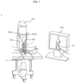
- FIG. 1 is a diagram showing a laser guidance system according to an embodiment of the present invention.
- a laser guidance system 1 guides an insertion location and posture of a fixing screw, a drill, a guide, or the like in a surgical operation to help a user (for example, a doctor) to precisely and easily perform the surgical operation.
- the laser guidance system 1 includes a C-arm fluoroscopy (hereinafter, a C-arm) 100, a display device 200 and laser projection apparatuses 300a, 300b, and may display operation information of an insertion location and an insertion angle planned on a C-arm image photographed using the C-arm 100 directly displayed on an affected part as an intersection point P of two line lasers 32a, 32b.
- a C-arm fluoroscopy hereinafter, a C-arm
- a display device 200 and laser projection apparatuses 300a, 300b
- laser projection apparatuses 300a, 300b may display operation information of an insertion location and an insertion angle planned on a C-arm image photographed using the C-arm 100 directly displayed on an affected part as an intersection point P of two line lasers 32a, 32b.
- the C-arm 100 is a device that scans the human body and photographs a surgical site, and a C-arm image, which is an image photographed by the C-arm, may be a 2D C-arm fluoroscopic image.
- the C-arm 100 may transmit the photographed image to the display device 200.
- the display device 200 may output the C-arm image and receive operation information from a user.
- the display device 200 may include a display panel displaying the C-arm image and an interface unit that provides a user interface (Ul) for allowing a user to apply a touch input and senses a touch input applied by the user. That is, the display device 200 provides a function for a user to graphically display and change operation information directly on the C-arm image, and thus the display panel may include a touch screen function or a separate touch pad.
- the display device 200 is configured as a display panel having a touch screen function as shown in FIG. 1 , the user may plan the operation information on the C-arm image displayed on the display panel by using an electrical pen 42 or by hand.
- the laser projection apparatuses 300a, 300b are devices that generate a line laser and projects the line laser on an affected part according to the operation information planned on the C-arm image, and the laser projection apparatuses 300a, 300b may be coupled to the C-arm 100 as shown in FIG. 1 .
- the laser projection apparatuses 300a, 300b may perform position matching between the C-arm 100 and the laser projection apparatuses 300a, 300b in order to project line lasers at a position according to the operation information planned on the C-arm image.
- the laser guidance system 1 may display the operation information on the affected part as an intersection point P of two line lasers 32a, 32b. Therefore, at least two laser projection apparatuses 300a, 300b may be provided.
- the laser projection apparatuses 300a, 300b will be described in more detail with reference to FIGS. 2 to 9 .
- FIG. 2 is a control block diagram showing the laser projection apparatus of FIG. 1 .
- the laser projection apparatus 300 may include a line laser module 310 for generating a line laser, a matching unit 320 for performing position matching between the C-arm 100 and the laser projection apparatus 300, and a control unit 330 for controlling the line laser module 310 according to the matching result.
- a line laser module 310 for generating a line laser
- a matching unit 320 for performing position matching between the C-arm 100 and the laser projection apparatus 300
- a control unit 330 for controlling the line laser module 310 according to the matching result.
- the line laser module 310 may generate a line laser.
- the configuration of the line laser module 310 for this function will be described with reference to FIG. 3 .
- FIG. 3 is a diagram schematically showing a line laser module.
- the line laser module 310 may be implemented to include a green laser 311, a rotation line generator 312, a rotating mirror 313, a first motor 314 and a second motor 315, and these configurations may be accommodated in a housing that defines the appearance of the line laser module 310.
- the green laser 311 may generate a laser beam.
- the configuration for laser generation is defined as the green laser 311 that generates a green laser beam, but the color of the laser beam is not limited.
- the rotation line generator 312 may transform the laser beam to the line laser 32 by rotating the laser beam around an origin. That is, the rotation line generator 312 may rotate the laser beam so that the laser beam consequently forms a plane and thus is transformed into the line laser 32 projected in a line form on the target.
- the rotation line generator 312 may receive two degree of freedom movement by the first motor 314.
- the rotation line generator 312 may rotate according to the operation of the first motor 314, so that the laser beam is rotated around the origin and transformed into the line laser 32.
- a rotation angle ( ⁇ 1 ) of the line laser 32 may be a rotation angle ( ⁇ 1 ) of the first motor 314, and its value may be calculated by the matching unit 320 and control unit 330, which is explained below.
- the rotating mirror 313 may be located to face the rotation line generator 312 to reflect the line laser 32.
- the rotating mirror 313 may change the direction of a rotation central axis of line laser 32. If the direction of the rotation central axis of the line laser 32 is changed, the direction (n l ) of the plane formed by the line laser 32 may be changed.
- Two degree of freedom movement of the rotating mirror 313 may be supported by the second motor 315.
- the rotating mirror 313 may change a direction (n m ) of the rotating mirror 313 according to the operation of the second motor 315.
- the rotating mirror 313 may reflect the line laser 32 at an angle of 45° with respect to the direction (n m ) of the rotating mirror 313.
- the line laser 32 may be projected on a target according to the direction (n m ) of the rotating mirror 313.
- the direction (n m ) of the rotating mirror 313 may be determined according to a rotation angle ( ⁇ 2 ) of the second motor 315, and the rotation angle ( ⁇ 2 ) may be calculated by the matching unit 320 and control unit 330, explained later.
- the first motor 314 and the second motor 315 may have two degree of freedom steering.
- the first motor 314 and the second motor 315 may operate under control of the control unit 330.
- the first motor 314 may be connected to the rotation line generator 312 to provide two degree of freedom movement to the rotation line generator 312.
- the second motor 315 may be connected to the rotating mirror 313 to provide two degree of freedom movement to the rotating mirror 313.
- the rotation angles ( ⁇ 1 , ⁇ 2 ) of the first motor 314 and the second motor 315 may be calculated from a vector ( Norm V L ) perpendicular to the plane formed by the line laser 32 projected to the affected part, respectively. This will be described later in detail.
- the laser projection apparatus 300 performs position matching between the C-arm 100 and the laser projection apparatus 300.
- the line laser module 310 may further include a calibration tool 336, and a C-arm marker appearing on the C-arm image may be attached to a predetermined position of the calibration tool 336 so as to check the position of the line laser module 310 based on the C-arm 100.
- FIG. 4 shows an example of a calibration tool included in the line laser module.
- the calibration tool 336 may have a checkerboard-shaped calibration pattern attached to a lower surface thereof.
- the calibration tool 336 may be mounted to the line laser module 310 to be located between the line laser module 310 and the C-arm 100. Therefore, the line laser 32 may be projected to the affected part through the calibration tool 336, and the calibration pattern may be projected on the C-arm image.
- the matching unit 320 performs calculation for position matching between the C-arm 100 and the laser projection apparatus 300, and may calculate a vertical vector ( Norm V L ) that is perpendicular to the plane formed by the line laser 32 in order to calculate the rotation angles ( ⁇ 1 , ⁇ 2 ) of the first motor 314 and the second motor 315, respectively.
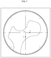
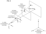
- FIGS. 5 to 7 are diagrams for illustrating coordinate systems used for matching positions of a C-arm and a laser projection apparatus.
- ⁇ C ⁇ represents a C-arm coordinate system based on the C-arm 100.
- ⁇ L1 ⁇ and ⁇ L2 ⁇ represent line laser module coordinate systems based on a first laser projection apparatus 31a and a second laser projection apparatus 31b, respectively, and more specifically, they are coordinate systems based on the origin of the line laser output from the line laser module 310 included in each laser projection apparatus 300.
- ⁇ M1 ⁇ and ⁇ M2 ⁇ represent C-arm marker coordinate systems based on C-arm markers attached to the first laser projection apparatus 31a and the second laser projection apparatus 31b, respectively.
- the matching unit 320 may derive a transformation matrix T M L between ⁇ M ⁇ and ⁇ L ⁇ and may also derive a transformation matrix T C M between ⁇ C ⁇ and ⁇ M ⁇ .
- the matching unit 320 may derive a transformation matrix T C L between ⁇ L ⁇ and ⁇ C ⁇ by using T M L and T C M , and may express the coordinate of ⁇ L1 ⁇ or ⁇ L2 ⁇ as a coordinate of ⁇ C ⁇ by using this transformation matrix.
- ⁇ i ⁇ represents a C-arm image coordinate system based on the C-arm image, which is a bi-axis coordinate system, unlike the tri-axial coordinate systems ⁇ C ⁇ , ⁇ L ⁇ , ⁇ M ⁇ .
- the matching unit 320 may calculate the coordinate of ⁇ i ⁇ in ⁇ C ⁇ .
- the matching unit 320 may first derive a transformation matrix T C M between ⁇ C ⁇ and ⁇ L ⁇ .
- the matching unit 320 may derive the transformation matrix T C M between ⁇ C ⁇ and ⁇ L ⁇ using the known Zhang's camera calibration method.
- a C-arm marker may be attached to the laser projection apparatus 300, and the C-arm marker may appear on the C-arm image.
- the matching unit 320 may calculate an extrinsic parameter of the C-arm marker using the Zhang's camera calibration method on the C-arm image.
- the matching unit 320 may calculate the extrinsic parameter of the C-arm marker based on a calibration pattern projected on the C-arm image.
- the specifications of the calibration tool 336 and the design information of the calibration pattern thereof may be stored in advance.
- the matching unit 320 may derive the transformation matrix T C M between ⁇ C ⁇ and ⁇ L ⁇ according to the extrinsic parameter of the C-arm marker, and may transform any one coordinate of ⁇ C ⁇ into a coordinate value of ⁇ M ⁇ by using the transformation matrix cT.
- the matching unit 320 may derive a transformation matrix T M L between ⁇ M ⁇ and ⁇ L ⁇ .
- the coordinate system ⁇ L ⁇ based on the origin of the line laser output from the line laser module 310 is the same as a coordinate system obtained by rotating the coordinate system ⁇ M ⁇ by 180° about the y-axis of based on the C-arm marker. Therefore, the matching unit 320 may derive the transformation matrix T M L between ⁇ M ⁇ and ⁇ L ⁇ as in Equation 1 below, and transform any one coordinate of ⁇ M ⁇ to the coordinate value of ⁇ L ⁇ using the transformation matrix T M L .
- T M L ⁇ 1 0 0 x 0 1 0 y 0 0 ⁇ 1 z 0 0 0 1
- x, y and z are determined according to the design of the calibration tool 336, and may be determined according to a distance between the origin of the line laser output from the line laser module 310 and the origin of the calibration pattern.
- the matching unit 320 may derive the transformation matrix C L T between ⁇ C ⁇ and ⁇ L ⁇ using T C M and T M L derived as above.
- the matching unit 320 may derive a transformation matrix T C L1 between ⁇ C ⁇ and ⁇ L1 ⁇ using T C M1 and T M1 L1 as in Equation 2 below, and may transform any one coordinate of ⁇ C ⁇ into a coordinate value of ⁇ L1 ⁇ using the transformation matrix T C L1 .
- the matching unit 320 may derive a transformation matrix T C L2 between ⁇ C ⁇ and ⁇ L2 ⁇ using C M 2 T and M 2 L 2 T as in Equation 3 below, and may transform any one coordinate of ⁇ C ⁇ into a coordinate value of ⁇ L2 ⁇ using the transformation matrix C L 2 T .
- the matching unit 320 may transform one point P img (x, y) of ⁇ i ⁇ into one point P (X c , Y c , Z c ) of ⁇ C ⁇ .
- P img (x, y) may be an insertion location displayed on the C-arm image by the user.
- the matching unit 320 may transform ⁇ i ⁇ into a normal coordinate system, and then transform into ⁇ C ⁇ in the normal coordinate system. This will be described with reference to FIG. 8 .
- FIG. 8 is a diagram for illustrating a method of displaying a point of a C-arm image coordinate system based on a C-arm image as a point of a C-arm coordinate system based on the C-arm.
- the matching unit 320 may obtain an intrinsic parameter k of the C-arm as in Equation 4 using the known Zhang's method, and may obtain a parameter for transforming ⁇ i ⁇ into a normal coordinate system as in Equations 5 and 6 below.
- the matching unit 320 may transform the normal coordinate system into ⁇ C ⁇ .
- the C-arm image is a plane parallel to the intensifier of the C-arm 100, and the distance between the C-arm 100 and a photographing target may checked in advance. For example, if the distance from the origin of ⁇ C ⁇ to the photographing target is d, P (X c , Y c , Z c ) may be calculated as in Equation 7 below.
- X C u ⁇ d
- Y C v ⁇ d
- Z C d
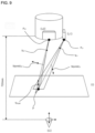
- the matching unit 320 may calculate an insertional vector according to the insertion angle received from the user. In addition, the matching unit 320 may calculate a coordinate representing the origin of the line laser module 310 in ⁇ C ⁇ . In addition, the matching unit 320 may calculate a vector ( Norm V L ) perpendicular to the plane formed by the line laser 32 according to the insertional vector and the coordinates representing the origin of the line laser module 310. This will be described with reference to FIG. 9 .
- FIG. 9 is a diagram for illustrating a vector calculated by a matching unit depicted in FIG. 2 .
- the matching unit 320 may calculate an insertional vector (V target ) according to the insertion angle ( ⁇ ) input by the user at the coordinate P (X c , Y c , Z c ) representing the insertion location in ⁇ C ⁇ .
- the matching unit 320 may calculate the coordinates (P L1 , P L2 ) representing the origin of the line laser module 310 in ⁇ C ⁇ by using the transformation matrix C L T between ⁇ C ⁇ and ⁇ L ⁇ as in Equation 8 below.
- P L 1 T L 1 L 1 C P 0 0,0
- P L 2 T L 2 L 2 C P 0 0,0
- the matching unit 320 may calculate a vector ( Norm V L ) perpendicular to the plane formed by the line laser 32 in ⁇ C ⁇ as in Equation 9 below.
- the matching unit 320 may calculate the vector ( Norm V L ) perpendicular to the plane formed by the line laser 32 by performing vector product a vector connecting the coordinate representing the origin of the line laser module 310 in ⁇ C ⁇ and the coordinate representing the insertion location and the insertional vector.
- V L 1 Norm V target ⁇ PP L 1 ⁇
- V L 2 Norm V target ⁇ PP L 2 ⁇
- the matching unit 320 may transform the vector ( Norm V L ) into a vector based on ⁇ L ⁇ , and the resulting vector of the line laser 32 may be expressed as in Equation 10 below.
- V L 1 R C L 1 V L 1 Norm
- V L 2 R C L 2 V L 2 Norm
- the control unit 330 may control the line laser module 310 based on the vector ( Norm V L ) perpendicular to the plane formed by the line laser 32 so that the line laser 32 according to Equation 10 may be projected onto the affected part. That is, the control unit 330 may control the first motor 314 and the second motor 315 by calculating the steering angles of the first motor 314 and the second motor 315 of the line laser module 310, respectively.
- the steering angle of the first motor 314 is referred to as a first rotation angle ( ⁇ 1 )
- the steering angle of the second motor 315 is referred to as a second rotation angle ( ⁇ 2 ).
- Equation 11 the vector ( Norm V L ) perpendicular to the plane formed by the line laser 32 may be expressed as in Equation 11 below.
- NormV L n l ⁇ 2 n l ⁇ n m n m
- n l may represent a direction facing the plane formed by the line laser 32
- n m may represent a direction of the rotating mirror 313.
- n l , n m and n l ⁇ n m may be expressed as in Equation 12 below by using the first rotation angle ( ⁇ 1 ) and the second rotation angle ( ⁇ 2 ).
- n l 0 cos ⁇ 1 sin ⁇ 2
- n m ⁇ 2 2 ⁇ 2 2 sin ⁇ 2 2 2 cos ⁇ 2
- n l ⁇ n m sin ⁇ 1 ⁇ ⁇ 2 2
- Equation 12 the vector ( Norm V L ) perpendicular to the plane formed by the line laser 32 may be expressed as in Equation 13 below.
- NormV L sin ⁇ 1 ⁇ ⁇ 2 cos ⁇ 1 ⁇ ⁇ 2 cos ⁇ 2 cos ⁇ 1 ⁇ ⁇ 2 sin ⁇ 2
- the control unit 330 may calculate the first rotation angle ( ⁇ 1 ) and the second rotation angle ( ⁇ 2 ), respectively, based on Equation 13. For example, the control unit 330 may calculate ⁇ 1 - ⁇ 2 by comparing the x value of the vector ( Norm V L ) perpendicular to the plane formed by the line laser 32 with sin( ⁇ 1 - ⁇ 2 ), calculate second rotation angle ( ⁇ 2 ) by applying the calculated ⁇ 1 - ⁇ 2 value to the y and z values of the vector ( Norm V L ) perpendicular to the plane formed by the line laser 32 first, and then calculate the first rotation angle ( ⁇ 1 ).
- the control unit 330 may control the first motor 314 and the second motor 315 according to the first rotation angle ( ⁇ 1 ) and the second rotation angle ( ⁇ 2 ) calculated as above.
- FIG. 10 a control method of the laser projection apparatus according to an embodiment of the present invention as shown in FIG. 2 will be described.
- FIG. 10 is a flowchart for illustrating a control method of the laser projection apparatus according to an embodiment of the present invention as shown in FIG. 2 .
- the laser projection apparatus 300 may calculate a coordinate representing the insertion location in the C-arm coordinate system (500).
- the laser projection apparatus 300 may transform P img (x, y), which is an insertion location displayed on the C-arm image by the user in ⁇ i ⁇ , into a point P (X c , Y c , Z c ) of ⁇ C ⁇ according to Equations 4 to 7.
- the laser projection apparatus 300 may transform ⁇ i ⁇ into a normal coordinate system, and then transform into ⁇ C ⁇ in the normal coordinate system.
- the laser projection apparatus 300 may calculate an insertional vector according to the coordinate representing the insertion location and the insertion angle (510).
- the laser projection apparatus 300 may calculate the insertional vector (V target ) according to the insertion angle ( ⁇ ) input by the user at the coordinate P (X c , Y c , Z c ) indicating the insertion location in ⁇ C ⁇ .
- the laser projection apparatus 300 may calculate the coordinate (P L1 , P L2 ) representing the origin of the line laser module 310 in the C-arm coordinate system (520).
- the laser projection apparatus 300 may calculate the coordinate (P L1 , P L2 ) representing the origin of the line laser module 310 in ⁇ C ⁇ using the transformation matrix C L T between ⁇ C ⁇ and ⁇ L ⁇ , as in Equation 8.
- the laser projection apparatus 300 may calculate a vector ( Norm V L ) perpendicular to the plane formed by the line laser 32 in the C-arm coordinate system according to the insertional vector (530).
- the laser projection apparatus 300 may calculate vector ( Norm V L ) perpendicular to the plane formed by the line laser 32 by performing vector product to a vector connecting the coordinate representing the origin of the line laser module 310 in ⁇ C ⁇ and the coordinate representing the insertion location and the insertional vector, as in Equation 9.
- the laser projection apparatus 300 may transform the vector ( Norm V L ) perpendicular to the plane formed by line laser 32 in the C-arm coordinate system into a line laser module coordinate system (540).
- the laser projection apparatus 300 may transform the vector ( Norm V L ) perpendicular to the plane formed by the line laser 32 based on ⁇ C ⁇ into a vector based on ⁇ L ⁇ , as in Equation 10.
- the laser projection apparatus 300 may control to generate the line laser 32 based on the vector ( Norm V L ) perpendicular to the plane formed by the line laser 32 (550).
- the laser projection apparatus 300 may control the first motor 314 and the second motor 315 by calculating the first rotation angle ( ⁇ 1 ) of the first motor 314 connected to the rotation line generator 312 that converts the laser beam into the line laser 32 based on Equation 13 and calculating the second rotation angle ( ⁇ 2 ) of the second motor 315 connected to the rotating mirror 313 that converts the rotation central axis of the line laser 32.
- the control method of laser projection apparatus may be implemented in the form of an application or program commands executable by various computer components and be recorded on a computer-readable recording medium.
- the computer-readable recording medium may include program commands, data files, data structures or the like solely or in combination.
- the program commands recorded on the computer-readable recording medium may be specially designed or configured for the present disclosure or known to and available by computer software engineers.
- the computer-readable recording medium includes, for example, magnetic media such as a hard disk, a floppy disk and a magnetic tape, optical media such as CD-ROM and DVD, magneto-optical media such as a floptical disk, hardware devices such as ROM, RAM and a flash memory, specially configured to store and perform program commands, or the like.
- the program commands include not only machine codes made by a complier but also high-level language codes executable by a computer by using an interpreter.
- the hardware device may be configured to operate as at least one software module to perform the operations of the present invention, or vice versa.
Landscapes
- Health & Medical Sciences (AREA)
- Life Sciences & Earth Sciences (AREA)
- Engineering & Computer Science (AREA)
- Surgery (AREA)
- Medical Informatics (AREA)
- Nuclear Medicine, Radiotherapy & Molecular Imaging (AREA)
- Molecular Biology (AREA)
- Heart & Thoracic Surgery (AREA)
- Pathology (AREA)
- Biomedical Technology (AREA)
- Animal Behavior & Ethology (AREA)
- General Health & Medical Sciences (AREA)
- Public Health (AREA)
- Veterinary Medicine (AREA)
- Oral & Maxillofacial Surgery (AREA)
- Physics & Mathematics (AREA)
- Theoretical Computer Science (AREA)
- General Engineering & Computer Science (AREA)
- Radiology & Medical Imaging (AREA)
- Optics & Photonics (AREA)
- General Physics & Mathematics (AREA)
- High Energy & Nuclear Physics (AREA)
- Biophysics (AREA)
- Data Mining & Analysis (AREA)
- Human Computer Interaction (AREA)
- Gynecology & Obstetrics (AREA)
- Bioinformatics & Computational Biology (AREA)
- Bioinformatics & Cheminformatics (AREA)
- Artificial Intelligence (AREA)
- Computer Vision & Pattern Recognition (AREA)
- Evolutionary Biology (AREA)
- Evolutionary Computation (AREA)
- Length Measuring Devices By Optical Means (AREA)
- Apparatus For Radiation Diagnosis (AREA)
- Laser Surgery Devices (AREA)
- Multimedia (AREA)
- Signal Processing (AREA)
Claims (13)
- Laserführungssystem (1), das zumindest zwei Laserprojektionsvorrichtungen (300, 300a, 300b, 31a, 31b) aufweist, um Bedienungsinformation eines Einführorts (P) und eines Einführwinkels (α), die von einem Benutzer auf einer Anzeigevorrichtung (200), die ein mittels einer C-Arm-Fluoroskopievorrichtung (100) fotografiertes C-Arm-Bild anzeigt, geplant wird, direkt auf ein betroffenes Teil zu projizieren,
wobei jede der Laser-Projektionsvorrichtungen aufweist:ein Linienlasermodul (310), das einen grünen Laser (311) aufweist, der konfiguriert ist, um einen Laserstrahl zu erzeugen, einen Rotationsliniengenerator (312), der konfiguriert ist, um durch Drehung des Laserstrahls um einen Ursprung den Laserstrahl in einen Linienlaser (32) umzuwandeln, um eine Ebene zu bilden, einen Rotationsspiegel (313), der konfiguriert ist, um eine Rotationsmittelachse des Linienlasers (32) zu ändern, einen ersten Motor (314), der mit dem Rotationsliniengenerator (312) verbunden und konfiguriert ist, um unter der Steuerung der Steuereinheit (330) zu arbeiten, sowie einen zweiten Motor (315), der mit dem Rotationsspiegel (313) verbunden und konfiguriert ist, um unter der Steuerung der Steuereinheit (330) zu arbeiten,eine Abgleicheinheit (320), die konfiguriert ist, um eine den Einführort (P) repräsentierende Koordinate in einem auf dem C-Arm-Fluoroskopiebild basierenden C-Arm-Koordinatensystem (C) zu berechnen, um einen Positionsabgleich zwischen der C-Arm-Fluoroskopievorrichtung (100) und jeder Laserprojektionsvorrichtung (300, 300a, 300b, 31a, 31b) durchzuführen, um einen Einführvektor (Vtarget) gemäß der den Einführort (P) repräsentierenden Koordinate und dem vom Benutzer eingegebenen Einsetzwinkel (α) zu berechnen; undeine Steuereinheit (330), die konfiguriert ist, um das Lasermodul (310) zu steuern,dadurch gekennzeichnet, dassdie Abgleicheinheit (320) ferner konfiguriert ist, um einen Vektor (NormVL), der senkrecht zu der Ebene ist, die durch den Linienlaser (32a, 32b) in dem C-Arm-Koordinatensystem (C) gebildet ist, gemäß dem Einführvektor (Vtarget) von dem Benutzer zu berechnen; unddie Steuereinheit (330) ferner konfiguriert ist, um Rotationswinkel (θ1, θ2) des ersten Motors (314) und des zweiten Motors (315) basierend auf dem Vektor (NormVL) zu steuern, der senkrecht zu der Ebene ist, die durch den auf das betroffene Teil projizierten Linienlaser (32) gebildet ist. - Das Laserführungssystem von Anspruch 1, wobei die Abgleicheinheit (320) ferner konfiguriert ist, um eine Koordinate zu berechnen, die den Ursprung in dem C-Arm-Koordinatensystem (C) repräsentiert, und um den zur Ebene senkrechten Vektor (NormVL), durch Ausführung eines Vektorprodukts zwischen einem Vektor, der die den Einführort (P) repräsentierende Koordinate mit der den Ursprung repräsentierenden Koordinate verbindet, und dem Einführvektor (Vtarget) zu berechnen;
wobei die Abgleicheinheit (320) bevorzugt ferner konfiguriert ist, um den Vektor (NormVL), der senkrecht zu der Ebene in dem C-Arm-Koordinatensystem (C) ist, in ein Linienlasermodul-Koordinatensystem (L) umzuwandeln, wobei das Linienlasermodul-Koordinatensystem (L) auf dem Linienlasermodul (310) beruht. - Das Laserführungssystem von Anspruch 1,
wobei die Abgleicheinheit (320) ferner konfiguriert ist, um in dem C-Arm-Bild einen extrinsischen Parameter eines an dem Linienlasermodul (310) angeordneten C-Arm-Markers zu berechnen, eine Transformationsmatrix zwischen dem C-Arm-Koordinatensystem (C) und einem auf dem C-Arm-Marker basierenden C-Arm-Markerkoordinatensystem (M) herzuleiten, eine Transformationsmatrix zwischen dem C-Arm-Markerkoordinatensystem (M) und einem auf dem Linienlasermodul (310) basierenden Linienlasermodul-Koordinatensystem (L) herzuleiten, und eine Transformationsmatrix zwischen dem C-Arm-Koordinatensystem (C) und dem Linienlasermodul-Koordinatensystem (L) herzuleiten. - Das Laserführungssystem von Anspruch 1,
wobei die Steuereinheit (330) ferner konfiguriert ist, um den ersten Motor (314) und den zweiten Motor (315) durch Berechnen jeweiliger Lenkwinkel des ersten Motors und des zweiten Motors aus dem zur Ebene senkrechten Vektor (NormVL) zu steuern. - Das Laserführungssystem von Anspruch 1,wobei das Linienlasermodul (310) ferner ein Kalibrierinstrument (336) aufweist, an dem ein Kalibriermuster angebracht ist, undwobei das Kalibrierinstrument (336) zwischen dem Linienlasermodul (310) und der C-Arm-Fluoroskopievorrichtung (100) angeordnet ist.
- Steuerverfahren einer Laserprojektionsvorrichtung (300, 300a, 300b, 31a, 31b), um Bedienungsinformation eines Einführorts (P) und eines Einführwinkels (α), die von einem Benutzer auf einer Anzeigevorrichtung (200), die ein mittels einer C-Arm-Fluoroskopievorrichtung (100) fotografiertes C-Arm-Bild anzeigt, geplant wird, direkt auf ein betroffenes Teil zu projizieren, wobei das Steuerverfahren aufweist:Berechnen einer Koordinate, die den Einführort (P) in einem auf dem C-Arm-Fluoroskopiebild basierenden C-Arm-Koordinatensystem (C) repräsentiert;Berechnen eines Einführvektors (Vtarget) gemäß der Eingabe vom Benutzer an der Koordinate (P (Xe, Yc, Zc)), die den Einführort (P) und den Einführwinkel (α) repräsentiert,Berechnen eines Vektors (NormVL), der senkrecht zu einer Ebene ist, die durch einen von der Laserprojektionsvorrichtung (300) erzeugten Linienlaser (32) in dem C-Arm-Koordinatensystem (C) gebildet ist, gemäß dem Einführvektor (Vtarget), wobei der Linienlaser (32) durch ein Linienlasermodul (310) der Laserprojektionsvorrichtung (300) erzeugt wird, wobei das Linienlasermodul (310) aufweist: einen grünen Laser (311), der konfiguriert ist, um einen Laserstrahl zu erzeugen; einen Rotationsliniengenerator (312), der konfiguriert ist, um durch Drehung des Laserstrahls um einen Ursprung den Laserstrahl in den Linienlaser (32) umzuwandeln,; einen Rotationsspiegel (313), der konfiguriert ist, um eine Rotationsmittelachse des Linienlasers (32) zu ändern; einen ersten Motor (314), der mit dem Rotationsliniengenerator (312) verbunden ist; sowie einen zweiten Motor (315), der mit dem Rotationsspiegel (313) verbunden ist; undSteuern des von der Laserprojektionsvorrichtung (300) zu erzeugenden Linienlasers (32) durch Steuern von Rotationswinkeln (θ1, θ2) des ersten Motors (314) und des zweiten Motors (315) basierend auf dem zur Ebene senkrechten Vektor (NormVL).
- Das Steuerverfahren von Anspruch 6,
wobei das Berechnen des zur Ebene senkrechten Vektors (NormVL) aufweist:Berechnen einer Koordinate, die einen Ursprung zur Rotation des Linienlasers in dem C-Arm-Koordinatensystem (C) repräsentiert; undBerechnen des zur Ebene senkrechten Vektors (NormVL) durch Ausführung eines Vektorprodukts zwischen einem Vektor, der die den Einführort repräsentierende Koordinate mit dem den Ursprung repräsentierenden Koordinate verbindet, und dem Einführvektor (Vtarget). - Das Steuerverfahren von Anspruch 6, das ferner aufweist:
Umwandeln des zur Ebene senkrechten Vektors (NormVL) in dem C-Arm-Koordinatensystem (C) in ein Linienlasermodul-Koordinatensystem (L). - Das Steuerverfahren von Anspruch 6, das ferner aufweist:
Berechnen eines extrinsischen Parameters eines C-Arm-Markers in dem C-Arm-Bild, Herleiten einer Transformationsmatrix zwischen dem C-Arm-Koordinatensystem (C) und einem auf dem C-Arm-Marker basierenden C-Arm-Markerkoordinatensystem (M), Herleiten einer Transformationsmatrix zwischen dem C-Arm-Markerkoordinatensystem (M) und einem Linienlasermodul-Koordinatensystem (L), und Herleiten einer Transformationsmatrix zwischen dem C-Arm-Koordinatensystem (C) und dem Linienlasermodul-Koordinatensystem (L). - Das Steuerverfahren von Anspruch 6,
wobei das Steuern des zu erzeugenden Linienlasers (32) ferner aufweist:
Steuern des ersten Motors (314) und des zweiten Motors (315) durch Berechnen jeweiliger Lenkwinkel des ersten Motors und des zweiten Motors aus dem zur Ebene senkrechten Vektor (NormVL). - Laserführungssystem, welches aufweist:eine C-Arm-Fluoroskopievorrichtung (100);eine Anzeigevorrichtung (200), die konfiguriert ist, um ein mittels einer C-Arm-Fluoroskopievorrichtung (100) fotografiertes Bild anzuzeigen, und um Benutzerbedienungsinformation eines Einführorts (P) und eines Einführwinkels (α) zu empfangen; undzumindest zwei Laserprojektionsvorrichtungen (300a, 300b), jeweils nach einem der Ansprüche 1 bis 5, die konfiguriert sind, um die Bedienungsinformation direkt auf ein betroffenes Teil zu projizieren.
- Das Laserführungssystem von Anspruch 11, wobei die Bedienungsinformation als Schnittpunkt von Linienlasern (32) angezeigt wird, der aus den zumindest zwei Laserprojektionsvorrichtungen (300a, 300b) erzeugt wird.
- Das Laserführungssystem von Anspruch 11, wobei die Anzeigevorrichtung (200) aufweist:eine Tafel, die konfiguriert ist, um das mittels der C-Arm-Fluoroskopievorrichtung (100) fotografierte Bild anzuzeigen; undeine Benutzerschnittstelle (UI), die in der Tafel vorgesehen und konfiguriert ist, um eine vom Benutzer angewendete Berührungseingabe zu detektieren.
Applications Claiming Priority (2)
| Application Number | Priority Date | Filing Date | Title |
|---|---|---|---|
| KR1020170180581A KR102114089B1 (ko) | 2017-12-27 | 2017-12-27 | 레이저 표적 투영장치 및 그 제어방법, 레이저 표적 투영장치를 포함하는 레이저 수술 유도 시스템 |
| PCT/KR2018/016393 WO2019132427A1 (ko) | 2017-12-27 | 2018-12-20 | 레이저 표적 투영장치 및 그 제어방법, 레이저 표적 투영장치를 포함하는 레이저 수술 유도 시스템 |
Publications (3)
| Publication Number | Publication Date |
|---|---|
| EP3733111A1 EP3733111A1 (de) | 2020-11-04 |
| EP3733111A4 EP3733111A4 (de) | 2021-10-20 |
| EP3733111B1 true EP3733111B1 (de) | 2023-07-26 |
Family
ID=67063888
Family Applications (1)
| Application Number | Title | Priority Date | Filing Date |
|---|---|---|---|
| EP18897337.4A Active EP3733111B1 (de) | 2017-12-27 | 2018-12-20 | Laserzielprojektionsvorrichtung und steuerungsverfahren dafür und laserchirurgieinduktionssystem mit laserzielprojektionsvorrichtung |
Country Status (4)
| Country | Link |
|---|---|
| US (1) | US11534261B2 (de) |
| EP (1) | EP3733111B1 (de) |
| KR (1) | KR102114089B1 (de) |
| WO (1) | WO2019132427A1 (de) |
Families Citing this family (14)
| Publication number | Priority date | Publication date | Assignee | Title |
|---|---|---|---|---|
| US10881362B2 (en) * | 2018-11-20 | 2021-01-05 | General Electric Company | Systems for laser alignment |
| CN110634551A (zh) * | 2019-10-15 | 2019-12-31 | 北京爱康宜诚医疗器材有限公司 | 截骨量的测量方法、测量装置、存储介质和处理器 |
| CN111419266A (zh) * | 2020-04-01 | 2020-07-17 | 杨军 | 实现c臂机精准拍摄的辅助装置及可精准拍摄的c臂机 |
| KR102388282B1 (ko) * | 2020-05-18 | 2022-04-18 | 박상호 | 씨암용 영상 처리 장치 |
| KR102446345B1 (ko) * | 2020-06-23 | 2022-09-23 | 한림대학교 산학협력단 | 유방 영상에 의해 획득된 병변부 판단 시스템의 제어 방법, 장치 및 프로그램 |
| CN112800582B (zh) * | 2020-12-30 | 2022-05-24 | 华南理工大学 | 一种结构光视觉传感器仿真激光线生成方法 |
| WO2022161610A1 (en) * | 2021-01-28 | 2022-08-04 | Brainlab Ag | Positioning medical views in augmented reality |
| CN113298875B (zh) * | 2021-07-28 | 2021-10-15 | 浙江华睿科技股份有限公司 | 激光定位数据的校验方法、装置、电子设备及存储介质 |
| CN114305732A (zh) * | 2022-01-27 | 2022-04-12 | 庄源东 | 一种基于术中透视影像的同轴可旋转激光定位及引导系统 |
| DE102022115822A1 (de) * | 2022-06-24 | 2024-01-04 | B. Braun New Ventures GmbH | Laser-Führungsroboter zur visuellen Projektion einer Führung eines Operationsplans, Projektionsverfahren und Laser-Führungsroboter-System |
| CN115399881B (zh) * | 2022-09-28 | 2025-07-22 | 佗道医疗科技有限公司 | 一种激光导航校准方法 |
| CN118279355B (zh) * | 2024-02-19 | 2025-11-18 | 南京诺源医疗器械有限公司 | 荧光内镜的校准方法及系统 |
| KR102923387B1 (ko) | 2025-05-20 | 2026-02-04 | 황인성 | C-암 방사선 영상장치용 치료 가이드 시스템 |
| KR102923388B1 (ko) | 2025-06-10 | 2026-02-04 | 황인성 | C-암 방사선 영상장치용 가이드광 조사장치 및 이를 이용한 치료 가이드 시스템 |
Family Cites Families (20)
| Publication number | Priority date | Publication date | Assignee | Title |
|---|---|---|---|---|
| JP3792257B2 (ja) | 1996-04-29 | 2006-07-05 | ノーザン・デジタル・インコーポレーテッド | 画像誘導手術システム |
| US6031888A (en) * | 1997-11-26 | 2000-02-29 | Picker International, Inc. | Fluoro-assist feature for a diagnostic imaging device |
| US7853311B1 (en) * | 1999-04-23 | 2010-12-14 | 3M Innovative Properties Company | Surgical targeting system |
| JP4110457B2 (ja) * | 2002-06-05 | 2008-07-02 | 株式会社日立メディコ | 医療画像診断装置 |
| KR100731052B1 (ko) | 2006-01-23 | 2007-06-22 | 한양대학교 산학협력단 | 미세침습 수술을 위한 컴퓨터통합 수술 보조시스템 |
| EP2004071B1 (de) * | 2006-03-30 | 2013-05-15 | Koninklijke Philips Electronics N.V. | Targeting-vorrichtung, computerlesbarer datenträger und programmelement |
| US8118818B2 (en) * | 2006-12-15 | 2012-02-21 | Ao Technology Ag | Method and device for computer assisted distal locking of intramedullary nails |
| US9119572B2 (en) * | 2007-10-24 | 2015-09-01 | Josef Gorek | Monitoring trajectory of surgical instrument during the placement of a pedicle screw |
| DE102009014154B4 (de) * | 2009-03-24 | 2021-01-07 | Siemens Healthcare Gmbh | Verfahren zur Kalibrierung der Position von einem Laserfächerstrahl zur Projektionsgeometrie eines Röntgengerätes und Röntgengerät |
| KR101152177B1 (ko) * | 2009-04-09 | 2012-06-18 | 의료법인 우리들의료재단 | 수술위치 자동 유도 방법 및 그 시스템과 수술위치의 유도기능을 갖춘 장치 |
| CA2744123C (en) * | 2010-06-22 | 2019-07-23 | Queen's University At Kingston | C-arm rotation encoding methods and apparatus |
| DE102010031943A1 (de) * | 2010-07-22 | 2012-01-26 | Siemens Aktiengesellschaft | Verfahren zur Markierung eines vorbestimmten Führungswegs eines medizinischen Instruments und Orientierungsvorrichtung |
| DE102011004747B4 (de) * | 2011-02-25 | 2019-05-23 | Siemens Healthcare Gmbh | Bildgebendes medizinisches Gerät mit wenigstens zwei Vorrichtungen zur Kennzeichnung jeweils einer Ebene im Raum |
| CN103945764B (zh) * | 2011-11-11 | 2016-11-16 | 皇家飞利浦有限公司 | 具有扩展的视场的c型臂系统 |
| US20140107473A1 (en) * | 2012-10-17 | 2014-04-17 | Cincinnati Children's Hospital Medical Center | Laser Guidance System for Interventions |
| US10433911B2 (en) * | 2013-09-18 | 2019-10-08 | iMIRGE Medical INC. | Optical targeting and visualization of trajectories |
| KR101650620B1 (ko) * | 2014-06-24 | 2016-08-24 | 경북대학교 산학협력단 | 레이저 수술 유도 장치 및 방법, 이를 수행하기 위한 기록 매체 |
| AU2016225968B2 (en) * | 2015-03-05 | 2020-07-23 | Think Surgical, Inc. | Methods for locating and tracking a tool axis |
| WO2017004482A1 (en) * | 2015-07-02 | 2017-01-05 | Board Of Regents, The University Of Texas System | Utilization of laser interstitial thermotherapy guided with real time thermal mri |
| WO2018168766A1 (ja) * | 2017-03-14 | 2018-09-20 | 国立大学法人北海道大学 | 放射線治療装置 |
-
2017
- 2017-12-27 KR KR1020170180581A patent/KR102114089B1/ko active Active
-
2018
- 2018-12-20 US US16/956,847 patent/US11534261B2/en active Active
- 2018-12-20 WO PCT/KR2018/016393 patent/WO2019132427A1/ko not_active Ceased
- 2018-12-20 EP EP18897337.4A patent/EP3733111B1/de active Active
Also Published As
| Publication number | Publication date |
|---|---|
| EP3733111A4 (de) | 2021-10-20 |
| US11534261B2 (en) | 2022-12-27 |
| WO2019132427A1 (ko) | 2019-07-04 |
| KR102114089B1 (ko) | 2020-05-22 |
| KR20190078853A (ko) | 2019-07-05 |
| EP3733111A1 (de) | 2020-11-04 |
| US20200322582A1 (en) | 2020-10-08 |
Similar Documents
| Publication | Publication Date | Title |
|---|---|---|
| US11534261B2 (en) | Laser projection apparatus, control method thereof, and laser guidance system including the apparatus | |
| EP3939509B1 (de) | Medizinisches bildgebungssystem auf c-arm-basis | |
| JP5065783B2 (ja) | 定位手術処置装置および方法 | |
| EP3254621B1 (de) | Spezialkalibrator für 3d-bilder, chirurgisches ortungssystem und verfahren | |
| KR102166149B1 (ko) | 페디클 스크류 고정 플래닝 시스템 및 방법 | |
| EP3256067B1 (de) | Elektronische vorrichtung zur bestimmung der ausrichtung eines instruments | |
| US10835318B2 (en) | Orthopedic fixation control and manipulation | |
| CN103607959B (zh) | 用于三维超声中导管的可视化的mpr 切片选择 | |
| CN111212609A (zh) | 使用用于将医疗设备放置在骨骼中的具有形状对准的增强现实的系统和方法 | |
| US20050251113A1 (en) | Computer assisted intramedullary rod surgery system with enhanced features | |
| EP2835150A1 (de) | Strahlentherapiesystem | |
| US20200085281A1 (en) | Method for supporting a user, computer program product, data medium and imaging system | |
| US20140107473A1 (en) | Laser Guidance System for Interventions | |
| CN104203142A (zh) | 手术辅助装置以及手术辅助程序 | |
| USRE40176E1 (en) | Apparatus and method for planning a stereotactic surgical procedure using coordinated fluoroscopy | |
| CN105555221A (zh) | 医疗针头路径显示 | |
| CN112515766B (zh) | 用于将x射线图像数据组与导航系统配准的方法和系统 | |
| US11304757B2 (en) | Orthopedic fixation control and visualization | |
| Majak et al. | Augmented reality visualization for aiding biopsy procedure according to computed tomography based virtual plan | |
| CN115645050B (zh) | 手术导航系统 | |
| KR102612603B1 (ko) | 2d-3d 이미지 정합 방법 및 이를 수행하는 수술용 로봇 시스템 | |
| Doke et al. | Fluoroscopy-based laser guidance system for linear surgical tool insertion depth control | |
| CN110114032B (zh) | 激光目标投影装置与C-arm影像的匹配方法、用于执行其的记录介质以及包括匹配单元的激光手术导引系统 | |
| CN119970168B (zh) | 导航穿刺方法、装置、设备及存储介质 | |
| US20230270507A1 (en) | Surgical Imaging And Display System, And Related Methods |
Legal Events
| Date | Code | Title | Description |
|---|---|---|---|
| STAA | Information on the status of an ep patent application or granted ep patent |
Free format text: STATUS: THE INTERNATIONAL PUBLICATION HAS BEEN MADE |
|
| PUAI | Public reference made under article 153(3) epc to a published international application that has entered the european phase |
Free format text: ORIGINAL CODE: 0009012 |
|
| STAA | Information on the status of an ep patent application or granted ep patent |
Free format text: STATUS: REQUEST FOR EXAMINATION WAS MADE |
|
| 17P | Request for examination filed |
Effective date: 20200623 |
|
| AK | Designated contracting states |
Kind code of ref document: A1 Designated state(s): AL AT BE BG CH CY CZ DE DK EE ES FI FR GB GR HR HU IE IS IT LI LT LU LV MC MK MT NL NO PL PT RO RS SE SI SK SM TR |
|
| AX | Request for extension of the european patent |
Extension state: BA ME |
|
| RIN1 | Information on inventor provided before grant (corrected) |
Inventor name: YU, JIHUN Inventor name: LEE, HYUNWOO Inventor name: JOUNG, SANGHYUN Inventor name: PARK, CHULWOO Inventor name: PARK, ILHYUNG Inventor name: PARK, YOUNGKYUN |
|
| DAV | Request for validation of the european patent (deleted) | ||
| DAX | Request for extension of the european patent (deleted) | ||
| A4 | Supplementary search report drawn up and despatched |
Effective date: 20210921 |
|
| RIC1 | Information provided on ipc code assigned before grant |
Ipc: A61B 34/10 20160101ALN20210915BHEP Ipc: A61B 90/13 20160101ALI20210915BHEP Ipc: G06F 3/0488 20130101ALI20210915BHEP Ipc: A61B 6/00 20060101ALI20210915BHEP Ipc: A61B 90/00 20160101AFI20210915BHEP |
|
| GRAP | Despatch of communication of intention to grant a patent |
Free format text: ORIGINAL CODE: EPIDOSNIGR1 |
|
| STAA | Information on the status of an ep patent application or granted ep patent |
Free format text: STATUS: GRANT OF PATENT IS INTENDED |
|
| RIC1 | Information provided on ipc code assigned before grant |
Ipc: A61B 34/10 20160101ALN20230213BHEP Ipc: A61B 17/00 20060101ALI20230213BHEP Ipc: A61B 90/13 20160101ALI20230213BHEP Ipc: G06F 3/0488 20130101ALI20230213BHEP Ipc: A61B 6/00 20060101ALI20230213BHEP Ipc: A61B 90/00 20160101AFI20230213BHEP |
|
| INTG | Intention to grant announced |
Effective date: 20230307 |
|
| GRAS | Grant fee paid |
Free format text: ORIGINAL CODE: EPIDOSNIGR3 |
|
| GRAA | (expected) grant |
Free format text: ORIGINAL CODE: 0009210 |
|
| STAA | Information on the status of an ep patent application or granted ep patent |
Free format text: STATUS: THE PATENT HAS BEEN GRANTED |
|
| AK | Designated contracting states |
Kind code of ref document: B1 Designated state(s): AL AT BE BG CH CY CZ DE DK EE ES FI FR GB GR HR HU IE IS IT LI LT LU LV MC MK MT NL NO PL PT RO RS SE SI SK SM TR |
|
| REG | Reference to a national code |
Ref country code: CH Ref legal event code: EP |
|
| REG | Reference to a national code |
Ref country code: IE Ref legal event code: FG4D |
|
| REG | Reference to a national code |
Ref country code: DE Ref legal event code: R096 Ref document number: 602018054309 Country of ref document: DE |
|
| P01 | Opt-out of the competence of the unified patent court (upc) registered |
Effective date: 20230728 |
|
| REG | Reference to a national code |
Ref country code: LT Ref legal event code: MG9D |
|
| REG | Reference to a national code |
Ref country code: NL Ref legal event code: MP Effective date: 20230726 |
|
| REG | Reference to a national code |
Ref country code: AT Ref legal event code: MK05 Ref document number: 1591046 Country of ref document: AT Kind code of ref document: T Effective date: 20230726 |
|
| PG25 | Lapsed in a contracting state [announced via postgrant information from national office to epo] |
Ref country code: NL Free format text: LAPSE BECAUSE OF FAILURE TO SUBMIT A TRANSLATION OF THE DESCRIPTION OR TO PAY THE FEE WITHIN THE PRESCRIBED TIME-LIMIT Effective date: 20230726 |
|
| PG25 | Lapsed in a contracting state [announced via postgrant information from national office to epo] |
Ref country code: GR Free format text: LAPSE BECAUSE OF FAILURE TO SUBMIT A TRANSLATION OF THE DESCRIPTION OR TO PAY THE FEE WITHIN THE PRESCRIBED TIME-LIMIT Effective date: 20231027 |
|
| PG25 | Lapsed in a contracting state [announced via postgrant information from national office to epo] |
Ref country code: IS Free format text: LAPSE BECAUSE OF FAILURE TO SUBMIT A TRANSLATION OF THE DESCRIPTION OR TO PAY THE FEE WITHIN THE PRESCRIBED TIME-LIMIT Effective date: 20231126 |
|
| PG25 | Lapsed in a contracting state [announced via postgrant information from national office to epo] |
Ref country code: SE Free format text: LAPSE BECAUSE OF FAILURE TO SUBMIT A TRANSLATION OF THE DESCRIPTION OR TO PAY THE FEE WITHIN THE PRESCRIBED TIME-LIMIT Effective date: 20230726 Ref country code: RS Free format text: LAPSE BECAUSE OF FAILURE TO SUBMIT A TRANSLATION OF THE DESCRIPTION OR TO PAY THE FEE WITHIN THE PRESCRIBED TIME-LIMIT Effective date: 20230726 Ref country code: PT Free format text: LAPSE BECAUSE OF FAILURE TO SUBMIT A TRANSLATION OF THE DESCRIPTION OR TO PAY THE FEE WITHIN THE PRESCRIBED TIME-LIMIT Effective date: 20231127 Ref country code: NO Free format text: LAPSE BECAUSE OF FAILURE TO SUBMIT A TRANSLATION OF THE DESCRIPTION OR TO PAY THE FEE WITHIN THE PRESCRIBED TIME-LIMIT Effective date: 20231026 Ref country code: LV Free format text: LAPSE BECAUSE OF FAILURE TO SUBMIT A TRANSLATION OF THE DESCRIPTION OR TO PAY THE FEE WITHIN THE PRESCRIBED TIME-LIMIT Effective date: 20230726 Ref country code: LT Free format text: LAPSE BECAUSE OF FAILURE TO SUBMIT A TRANSLATION OF THE DESCRIPTION OR TO PAY THE FEE WITHIN THE PRESCRIBED TIME-LIMIT Effective date: 20230726 Ref country code: IS Free format text: LAPSE BECAUSE OF FAILURE TO SUBMIT A TRANSLATION OF THE DESCRIPTION OR TO PAY THE FEE WITHIN THE PRESCRIBED TIME-LIMIT Effective date: 20231126 Ref country code: HR Free format text: LAPSE BECAUSE OF FAILURE TO SUBMIT A TRANSLATION OF THE DESCRIPTION OR TO PAY THE FEE WITHIN THE PRESCRIBED TIME-LIMIT Effective date: 20230726 Ref country code: GR Free format text: LAPSE BECAUSE OF FAILURE TO SUBMIT A TRANSLATION OF THE DESCRIPTION OR TO PAY THE FEE WITHIN THE PRESCRIBED TIME-LIMIT Effective date: 20231027 Ref country code: FI Free format text: LAPSE BECAUSE OF FAILURE TO SUBMIT A TRANSLATION OF THE DESCRIPTION OR TO PAY THE FEE WITHIN THE PRESCRIBED TIME-LIMIT Effective date: 20230726 Ref country code: AT Free format text: LAPSE BECAUSE OF FAILURE TO SUBMIT A TRANSLATION OF THE DESCRIPTION OR TO PAY THE FEE WITHIN THE PRESCRIBED TIME-LIMIT Effective date: 20230726 |
|
| PG25 | Lapsed in a contracting state [announced via postgrant information from national office to epo] |
Ref country code: PL Free format text: LAPSE BECAUSE OF FAILURE TO SUBMIT A TRANSLATION OF THE DESCRIPTION OR TO PAY THE FEE WITHIN THE PRESCRIBED TIME-LIMIT Effective date: 20230726 |
|
| PG25 | Lapsed in a contracting state [announced via postgrant information from national office to epo] |
Ref country code: ES Free format text: LAPSE BECAUSE OF FAILURE TO SUBMIT A TRANSLATION OF THE DESCRIPTION OR TO PAY THE FEE WITHIN THE PRESCRIBED TIME-LIMIT Effective date: 20230726 |
|
| REG | Reference to a national code |
Ref country code: DE Ref legal event code: R097 Ref document number: 602018054309 Country of ref document: DE |
|
| PG25 | Lapsed in a contracting state [announced via postgrant information from national office to epo] |
Ref country code: SM Free format text: LAPSE BECAUSE OF FAILURE TO SUBMIT A TRANSLATION OF THE DESCRIPTION OR TO PAY THE FEE WITHIN THE PRESCRIBED TIME-LIMIT Effective date: 20230726 Ref country code: RO Free format text: LAPSE BECAUSE OF FAILURE TO SUBMIT A TRANSLATION OF THE DESCRIPTION OR TO PAY THE FEE WITHIN THE PRESCRIBED TIME-LIMIT Effective date: 20230726 Ref country code: ES Free format text: LAPSE BECAUSE OF FAILURE TO SUBMIT A TRANSLATION OF THE DESCRIPTION OR TO PAY THE FEE WITHIN THE PRESCRIBED TIME-LIMIT Effective date: 20230726 Ref country code: EE Free format text: LAPSE BECAUSE OF FAILURE TO SUBMIT A TRANSLATION OF THE DESCRIPTION OR TO PAY THE FEE WITHIN THE PRESCRIBED TIME-LIMIT Effective date: 20230726 Ref country code: DK Free format text: LAPSE BECAUSE OF FAILURE TO SUBMIT A TRANSLATION OF THE DESCRIPTION OR TO PAY THE FEE WITHIN THE PRESCRIBED TIME-LIMIT Effective date: 20230726 Ref country code: CZ Free format text: LAPSE BECAUSE OF FAILURE TO SUBMIT A TRANSLATION OF THE DESCRIPTION OR TO PAY THE FEE WITHIN THE PRESCRIBED TIME-LIMIT Effective date: 20230726 Ref country code: SK Free format text: LAPSE BECAUSE OF FAILURE TO SUBMIT A TRANSLATION OF THE DESCRIPTION OR TO PAY THE FEE WITHIN THE PRESCRIBED TIME-LIMIT Effective date: 20230726 |
|
| PG25 | Lapsed in a contracting state [announced via postgrant information from national office to epo] |
Ref country code: IT Free format text: LAPSE BECAUSE OF FAILURE TO SUBMIT A TRANSLATION OF THE DESCRIPTION OR TO PAY THE FEE WITHIN THE PRESCRIBED TIME-LIMIT Effective date: 20230726 |
|
| PLBE | No opposition filed within time limit |
Free format text: ORIGINAL CODE: 0009261 |
|
| STAA | Information on the status of an ep patent application or granted ep patent |
Free format text: STATUS: NO OPPOSITION FILED WITHIN TIME LIMIT |
|
| 26N | No opposition filed |
Effective date: 20240429 |
|
| PG25 | Lapsed in a contracting state [announced via postgrant information from national office to epo] |
Ref country code: SI Free format text: LAPSE BECAUSE OF FAILURE TO SUBMIT A TRANSLATION OF THE DESCRIPTION OR TO PAY THE FEE WITHIN THE PRESCRIBED TIME-LIMIT Effective date: 20230726 |
|
| REG | Reference to a national code |
Ref country code: CH Ref legal event code: PL |
|
| PG25 | Lapsed in a contracting state [announced via postgrant information from national office to epo] |
Ref country code: LU Free format text: LAPSE BECAUSE OF NON-PAYMENT OF DUE FEES Effective date: 20231220 |
|
| PG25 | Lapsed in a contracting state [announced via postgrant information from national office to epo] |
Ref country code: MC Free format text: LAPSE BECAUSE OF FAILURE TO SUBMIT A TRANSLATION OF THE DESCRIPTION OR TO PAY THE FEE WITHIN THE PRESCRIBED TIME-LIMIT Effective date: 20230726 |
|
| REG | Reference to a national code |
Ref country code: BE Ref legal event code: MM Effective date: 20231231 |
|
| PG25 | Lapsed in a contracting state [announced via postgrant information from national office to epo] |
Ref country code: MC Free format text: LAPSE BECAUSE OF FAILURE TO SUBMIT A TRANSLATION OF THE DESCRIPTION OR TO PAY THE FEE WITHIN THE PRESCRIBED TIME-LIMIT Effective date: 20230726 Ref country code: LU Free format text: LAPSE BECAUSE OF NON-PAYMENT OF DUE FEES Effective date: 20231220 |
|
| REG | Reference to a national code |
Ref country code: IE Ref legal event code: MM4A |
|
| PG25 | Lapsed in a contracting state [announced via postgrant information from national office to epo] |
Ref country code: IE Free format text: LAPSE BECAUSE OF NON-PAYMENT OF DUE FEES Effective date: 20231220 |
|
| PG25 | Lapsed in a contracting state [announced via postgrant information from national office to epo] |
Ref country code: BE Free format text: LAPSE BECAUSE OF NON-PAYMENT OF DUE FEES Effective date: 20231231 |
|
| PG25 | Lapsed in a contracting state [announced via postgrant information from national office to epo] |
Ref country code: CH Free format text: LAPSE BECAUSE OF NON-PAYMENT OF DUE FEES Effective date: 20231231 |
|
| PG25 | Lapsed in a contracting state [announced via postgrant information from national office to epo] |
Ref country code: IE Free format text: LAPSE BECAUSE OF NON-PAYMENT OF DUE FEES Effective date: 20231220 Ref country code: CH Free format text: LAPSE BECAUSE OF NON-PAYMENT OF DUE FEES Effective date: 20231231 Ref country code: BE Free format text: LAPSE BECAUSE OF NON-PAYMENT OF DUE FEES Effective date: 20231231 |
|
| PG25 | Lapsed in a contracting state [announced via postgrant information from national office to epo] |
Ref country code: BG Free format text: LAPSE BECAUSE OF FAILURE TO SUBMIT A TRANSLATION OF THE DESCRIPTION OR TO PAY THE FEE WITHIN THE PRESCRIBED TIME-LIMIT Effective date: 20230726 |
|
| PG25 | Lapsed in a contracting state [announced via postgrant information from national office to epo] |
Ref country code: BG Free format text: LAPSE BECAUSE OF FAILURE TO SUBMIT A TRANSLATION OF THE DESCRIPTION OR TO PAY THE FEE WITHIN THE PRESCRIBED TIME-LIMIT Effective date: 20230726 |
|
| PG25 | Lapsed in a contracting state [announced via postgrant information from national office to epo] |
Ref country code: CY Free format text: LAPSE BECAUSE OF FAILURE TO SUBMIT A TRANSLATION OF THE DESCRIPTION OR TO PAY THE FEE WITHIN THE PRESCRIBED TIME-LIMIT; INVALID AB INITIO Effective date: 20181220 |
|
| PG25 | Lapsed in a contracting state [announced via postgrant information from national office to epo] |
Ref country code: HU Free format text: LAPSE BECAUSE OF FAILURE TO SUBMIT A TRANSLATION OF THE DESCRIPTION OR TO PAY THE FEE WITHIN THE PRESCRIBED TIME-LIMIT; INVALID AB INITIO Effective date: 20181220 |
|
| PG25 | Lapsed in a contracting state [announced via postgrant information from national office to epo] |
Ref country code: TR Free format text: LAPSE BECAUSE OF FAILURE TO SUBMIT A TRANSLATION OF THE DESCRIPTION OR TO PAY THE FEE WITHIN THE PRESCRIBED TIME-LIMIT Effective date: 20230726 |
|
| PGFP | Annual fee paid to national office [announced via postgrant information from national office to epo] |
Ref country code: GB Payment date: 20251219 Year of fee payment: 8 |
|
| PGFP | Annual fee paid to national office [announced via postgrant information from national office to epo] |
Ref country code: FR Payment date: 20251229 Year of fee payment: 8 |
|
| PGFP | Annual fee paid to national office [announced via postgrant information from national office to epo] |
Ref country code: DE Payment date: 20251229 Year of fee payment: 8 |