EP3733073B1 - Multifunktionales röntgen-, tomographie- und fluoroskopiegerät - Google Patents
Multifunktionales röntgen-, tomographie- und fluoroskopiegerät Download PDFInfo
- Publication number
- EP3733073B1 EP3733073B1 EP18857389.3A EP18857389A EP3733073B1 EP 3733073 B1 EP3733073 B1 EP 3733073B1 EP 18857389 A EP18857389 A EP 18857389A EP 3733073 B1 EP3733073 B1 EP 3733073B1
- Authority
- EP
- European Patent Office
- Prior art keywords
- frame
- tomography
- board
- radiography
- fluoroscopy
- Prior art date
- Legal status (The legal status is an assumption and is not a legal conclusion. Google has not performed a legal analysis and makes no representation as to the accuracy of the status listed.)
- Active
Links
Images


Classifications
-
- A—HUMAN NECESSITIES
- A61—MEDICAL OR VETERINARY SCIENCE; HYGIENE
- A61B—DIAGNOSIS; SURGERY; IDENTIFICATION
- A61B6/00—Apparatus or devices for radiation diagnosis; Apparatus or devices for radiation diagnosis combined with radiation therapy equipment
- A61B6/42—Arrangements for detecting radiation specially adapted for radiation diagnosis
-
- A—HUMAN NECESSITIES
- A61—MEDICAL OR VETERINARY SCIENCE; HYGIENE
- A61B—DIAGNOSIS; SURGERY; IDENTIFICATION
- A61B6/00—Apparatus or devices for radiation diagnosis; Apparatus or devices for radiation diagnosis combined with radiation therapy equipment
- A61B6/02—Arrangements for diagnosis sequentially in different planes; Stereoscopic radiation diagnosis
- A61B6/03—Computed tomography [CT]
- A61B6/032—Transmission computed tomography [CT]
-
- A—HUMAN NECESSITIES
- A61—MEDICAL OR VETERINARY SCIENCE; HYGIENE
- A61B—DIAGNOSIS; SURGERY; IDENTIFICATION
- A61B6/00—Apparatus or devices for radiation diagnosis; Apparatus or devices for radiation diagnosis combined with radiation therapy equipment
- A61B6/04—Positioning of patients; Tiltable beds or the like
- A61B6/0407—Supports, e.g. tables or beds, for the body or parts of the body
-
- A—HUMAN NECESSITIES
- A61—MEDICAL OR VETERINARY SCIENCE; HYGIENE
- A61B—DIAGNOSIS; SURGERY; IDENTIFICATION
- A61B6/00—Apparatus or devices for radiation diagnosis; Apparatus or devices for radiation diagnosis combined with radiation therapy equipment
- A61B6/06—Diaphragms
-
- A—HUMAN NECESSITIES
- A61—MEDICAL OR VETERINARY SCIENCE; HYGIENE
- A61B—DIAGNOSIS; SURGERY; IDENTIFICATION
- A61B6/00—Apparatus or devices for radiation diagnosis; Apparatus or devices for radiation diagnosis combined with radiation therapy equipment
- A61B6/44—Constructional features of apparatus for radiation diagnosis
- A61B6/4429—Constructional features of apparatus for radiation diagnosis related to the mounting of source units and detector units
- A61B6/4435—Constructional features of apparatus for radiation diagnosis related to the mounting of source units and detector units the source unit and the detector unit being coupled by a rigid structure
- A61B6/4441—Constructional features of apparatus for radiation diagnosis related to the mounting of source units and detector units the source unit and the detector unit being coupled by a rigid structure the rigid structure being a C-arm or U-arm
-
- A—HUMAN NECESSITIES
- A61—MEDICAL OR VETERINARY SCIENCE; HYGIENE
- A61B—DIAGNOSIS; SURGERY; IDENTIFICATION
- A61B6/00—Apparatus or devices for radiation diagnosis; Apparatus or devices for radiation diagnosis combined with radiation therapy equipment
- A61B6/44—Constructional features of apparatus for radiation diagnosis
- A61B6/4429—Constructional features of apparatus for radiation diagnosis related to the mounting of source units and detector units
- A61B6/4452—Constructional features of apparatus for radiation diagnosis related to the mounting of source units and detector units the source unit and the detector unit being able to move relative to each other
-
- A—HUMAN NECESSITIES
- A61—MEDICAL OR VETERINARY SCIENCE; HYGIENE
- A61B—DIAGNOSIS; SURGERY; IDENTIFICATION
- A61B6/00—Apparatus or devices for radiation diagnosis; Apparatus or devices for radiation diagnosis combined with radiation therapy equipment
- A61B6/46—Arrangements for interfacing with the operator or the patient
- A61B6/461—Displaying means of special interest
- A61B6/466—Displaying means of special interest adapted to display 3D data
-
- A—HUMAN NECESSITIES
- A61—MEDICAL OR VETERINARY SCIENCE; HYGIENE
- A61B—DIAGNOSIS; SURGERY; IDENTIFICATION
- A61B6/00—Apparatus or devices for radiation diagnosis; Apparatus or devices for radiation diagnosis combined with radiation therapy equipment
- A61B6/48—Diagnostic techniques
- A61B6/486—Diagnostic techniques involving generating temporal series of image data
- A61B6/487—Diagnostic techniques involving generating temporal series of image data involving fluoroscopy
-
- A—HUMAN NECESSITIES
- A61—MEDICAL OR VETERINARY SCIENCE; HYGIENE
- A61B—DIAGNOSIS; SURGERY; IDENTIFICATION
- A61B6/00—Apparatus or devices for radiation diagnosis; Apparatus or devices for radiation diagnosis combined with radiation therapy equipment
- A61B6/52—Devices using data or image processing specially adapted for radiation diagnosis
- A61B6/5211—Devices using data or image processing specially adapted for radiation diagnosis involving processing of medical diagnostic data
-
- G—PHYSICS
- G01—MEASURING; TESTING
- G01T—MEASUREMENT OF NUCLEAR OR X-RADIATION
- G01T1/00—Measuring X-radiation, gamma radiation, corpuscular radiation, or cosmic radiation
- G01T1/16—Measuring radiation intensity
- G01T1/28—Measuring radiation intensity with secondary-emission detectors
Definitions
- the object of the present invention is universal equipment for the performance of radiography, tomography and fluoroscopy enabling the taking of conventional two-dimensional radiographs, three-dimensional tomographs and fluoroscopic images.
- the present invention is characterised by the particular characteristics presented by each of the elements forming part the equipment and the interconnection between the same, in such a way that the same is constituted as a versatile item of equipment providing multiple functions, such as the performance of two-dimensional radiographs and three-dimensional tomographs, and likewise fluoroscopy.
- the present invention is included in the field of x-ray machines designed for the examination of both humans and animals.
- All the above equipment presents aspects that are amenable to improvement, in some cases because they do not permit the execution of 2D radiographs throughout the length of the patient, enabling the viewing of the entirety of the same; in others it is not possible to perform 3D tomography, in others because it is not possible to extend the field of view and perform large-scale 3D tomographs.
- the object of the present invention is equipment such as that described below and whose essential nature is revealed in the first claim; it being possible to perform both two-dimensional radiographs and three-dimensional tomographs, and also fluoroscopic images, it also being a compact item of equipment which does not require large spaces for its installation, and which in turn enables simple access to the patient during the obtaining of the images.
- the equipment for the performance of radiography, tomography and fluoroscopy comprises:
- the C-shaped arch comprises:
- the emission assembly may feature an asymmetric collimator comprising a number of blinds which may move independently and asymmetrically as required, in order to prevent the undesired irradiation of areas.
- the "flat panel” or receiver presents the possibility of lateral displacement in a direction transversal to the greater dimension of the board and toward both sides, this enabling an increase in the field of view for tomography.
- the arch is configured so as to rotate in both directions (clockwise and anti-clockwise) with regard to an imaginary axis parallel to the greater dimension of the board.
- the arch may feature means which enables it to rotate in such a way that it may remain horizontal with regard to the plane of the floor; furthermore, the column further comprises means enabling it, in addition to its horizontal displacement, to be displaced or rotated with regard to a vertical axis passing through the column itself in such a way as to permit the arch to be disposed in a horizontal position without interfering with the table.
- this is compact equipment which does not require large spaces for its installation; it enables access to the patient during the obtaining of images; it presents an ample field of view for the performance of radiographs on patients (be they animal or human) of any size, and further enables simple accommodation of the patient on the board, this being height-adjustable.
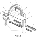
- a radiography x-ray machine may be observed; this comprises, among other elements, a board (1) supported by a number of height-adjustable motorised legs (2), enabling the board (1) to float with regard to the remainder of the equipment, and to move on the plane thereof. It further comprises a C-shaped arch (3) disposed transversally to the greater dimension (D) of the board (1), in such a way that the latter is housed within the internal space comprised between the two free extremities (3' and 3") of the arch (3).
- the arch (3) is slidingly installed on a column (4) by means of a transmission mechanism (5), which may be a linear guide or a roller bearing.
- Said transmission mechanism (5) or roller bearing is configured in order to slide or roll along the extension of the arch (3) while the latter rotates with regard to an imaginary rotational axis (13) parallel to the greater dimension (D) of the board (1).
- the column (4) in turn is disposed on a rail (12) located parallel to the greater dimension (D) of the board, along which the column (4), attached to the arch (3) is displaced longitudinally with regard to said board (1).
- the C-shaped arch (3) presents at its lower extremity (3') a "flat panel” or x-ray receiver (6), while at its upper extremity it holds the x-ray emission assembly (7), comprised of an x-ray tube (8) and a collimator (9).
- the arch (3) is linked to the x-ray emission assembly (7) by means of a connecting element (14).
- the x-ray emission assembly may include a screen or monitor (10) for the viewing of the images captured.
- the screen or monitor may also be disposed beside the equipment, as portrayed in figure 1 , or may be installed on the arch at the extremity where the x-ray tube is located.
- Figure 2 portrays one of the particular characteristics of the equipment, this being the possibility that the "flat panel” (6) or receiver is configured so as to make possible its lateral displacement in an orientation transversal to the greater dimension of the board, and in both directions, a feature which enables an increase in the field of view (11) in tomography.
- the "flat panel" or receiver is configured to take several photographs simultaneously, enabling the performance of real-time fluoroscopy.
- the arch (3) is configured to rotate in both directions around an imaginary rotational axis (13) parallel to the greater dimension (D) of the board (1), in such a way that it enables the obtaining of the complete image of the patient without the need to perform a complete 360o rotation of the C-shaped arch (3).
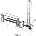
- Figure 4 portrays an additional embodiment of the invention wherein the guide rail (12) presents a length greater than the dimension of the table, formed by the board (1) and the legs (2), and, furthermore, the arch (3) presents the particular characteristic of the possibility of rotation with regard to a horizontal axis (15) with regard to the plane of the floor, and passing through the point of attachment to the column (4), where the column (4) presents a greater height than that portrayed in the previous embodiments.
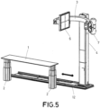
- Figure 4 portrays the arch (3) at the lowest position on the column (4), while figure 5 portrays the arch (3) at the highest position.
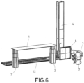
- Figure 6 portrays the arch (3) at the lowest position possible, where the arch has been moved along its point of connection, with the column (4) close to the receiver (6).
- Figure 7 portrays the arch (3) at the highest position on the column (4), where the arch has been moved along its point of connection, with the column (4) close to the x-ray emission assembly (7).
- the multi-purpose equipment for the performance of radiography, tomography and fluoroscopy comprises:
- the equipment comprises a rail (12) that can be coupled to the floor and parallel to the longer side of the board (1), on which the first body (16) and the frame (3) are displaced in a direction parallel to the longer side of the board (1).
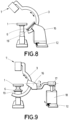
- the equipment shown in Figure 8 is mostly known because the x-ray tube of the radiation emission assembly is intended to perform 2D and 3D radiographs of the patient and real-time fluoroscopy, and the x-ray detection assembly comprises a dynamic flat panel (6) intended to receive x-rays for performing 2D and 3D radiographs and taking various simultaneous photographs to perform real-time fluoroscopy.
- the first body (16) internally comprises a second drive unit and a second transmission mechanism that facilitate the guided displacement of the first body (16) on the rail (12).
- FIG. 9 shows another embodiment of the equipment portrayed in Figure 9 , wherein, unlike Figure 8 , the first body (16) is mounted in a rotational mechanism (17) that facilitates the total rotation of the first body (16) and frame (3) around a horizontal axis contained in the plane of the frame (3); moreover, it is observed that the equipment comprises a second body (18) with respect to which the height of the rotational mechanism (17) can be displaced and therefore, the first body (16) and the frame (3), the second body (18) having a third drive unit and a third transmission mechanism that facilitate the guided displacement of the second body (18) on the rail (12) in a direction parallel to the longer side of the board (1).
- the dynamic flat panel (6) is mounted on the lower end of the frame (3) with intermediation of a structure (19) that enables the displacement of the board (1) in a direction perpendicular to the plane of the frame (3).
Landscapes
- Health & Medical Sciences (AREA)
- Life Sciences & Earth Sciences (AREA)
- Engineering & Computer Science (AREA)
- Medical Informatics (AREA)
- Physics & Mathematics (AREA)
- High Energy & Nuclear Physics (AREA)
- Molecular Biology (AREA)
- General Health & Medical Sciences (AREA)
- Surgery (AREA)
- Veterinary Medicine (AREA)
- Nuclear Medicine, Radiotherapy & Molecular Imaging (AREA)
- Optics & Photonics (AREA)
- Pathology (AREA)
- Radiology & Medical Imaging (AREA)
- Biomedical Technology (AREA)
- Heart & Thoracic Surgery (AREA)
- Biophysics (AREA)
- Animal Behavior & Ethology (AREA)
- Public Health (AREA)
- General Physics & Mathematics (AREA)
- Spectroscopy & Molecular Physics (AREA)
- Human Computer Interaction (AREA)
- Pulmonology (AREA)
- Theoretical Computer Science (AREA)
- Computer Vision & Pattern Recognition (AREA)
- Apparatus For Radiation Diagnosis (AREA)
Claims (11)
- Multifunktionales Röntgen-, Tomografie- und Fluoroskopiegerät, das Folgendes umfasst:einen Tisch, der mit einer Platte (1) versehen ist, die längere Seiten und kürzere Seiten aufweist, wobei die Platte (1) anhand von Mitteln höhenverstellbarer Beine, die die Platte (1) tragen, vertikal verschiebbar ist,einen Rahmen (3), der im Wesentlichen C-förmig und zur längeren Seite der Platte (1) schräg verschoben ist, die für eine Drehbewegung in beide Richtungen um eine zentrale Drehachse senkrecht zur Ebene des Rahmens (3) konfiguriert ist, wobei der Rahmen (3) mit einem oberen äußersten Ende (3") und einem unteren äußerstes Ende (3') versehen ist,einen ersten Körper (16), an dem der Rahmen (3) befestigt ist, der eine erste Antriebseinheit und einen ersten Übertragungsmechanismus (5) beinhaltet, der die gleitende Drehbewegung des Rahmens (3) bewirkt,eine Strahlungsemissionsanordnung (7), die am oberen äußersten Ende (3") des Rahmens (1) eingerichtet ist und eine Röntgenröhre (8) und einen Kollimator (9) umfasst,eine Röntgendetektionseinheit, die am unteren äußersten Ende (3') des Rahmens (3) befestigt ist,eine Schiene (12), die dazu konfiguriert ist, mit dem Boden und parallel zur längeren Seite der Platte (1) gekoppelt zu werden, und auf der der erste Körper (16) und der Rahmen (3) in eine Richtung parallel zur längeren Seite der Platte (1) verschoben werden kann,dadurch gekennzeichnet, dass die Röntgenröhre der Strahlungsemissionsanordnung (7) dazu konfiguriert ist, 2D-Röntgenaufnahmen und 3D-Tomografien des Patienten und Echtzeitfluoroskopie durchzuführen, unddie Röntgendetektionseinheit eine dynamische flache Tafel (6) umfasst, die dazu konfiguriert ist, Röntgenstrahlen zur Durchführung von 2D-Röntgenaufnahmen und 3D-Tomografien zu empfangen und mehrere aufeinander folgende Fotografien aufzunehmen, um Echtzeitfluoroskopie durchzuführen, wobei die flache Tafel seitlich in eine Ausrichtung verschiebbar ist, die schräg zur größeren Abmessung der Platte und in beide Richtungen ist, was eine Vergrößerung des Sichtfelds in der Tomografie ermöglicht,und dass das Gerät ferner ein Verbindungselement (14) umfasst, das sich vom oberen äußersten Ende (3") des Rahmens (3) erstreckt und die Strahlungsemissionsanordnung (7) mit dem oberen äußersten Ende (3") verbindet.
- Multifunktionales Röntgen-, Tomografie- und Fluoroskopiegerät nach Anspruch 1, wobei der Kollimator asymmetrisch ist, umfassend eine Anzahl von Blenden, die sich bei Bedarf unabhängig und asymmetrisch bewegen können, um die Bestrahlung unerwünschter Stellen zu verhindern.
- Multifunktionales Röntgen-, Tomografie- und Fluoroskopiegerät nach Anspruch 1, wobei es ferner einen Bildschirm oder Monitor (10) zum Betrachten der erfassten Bilder umfasst.
- Multifunktionales Röntgen-, Tomografie- und Fluoroskopiegerät nach Anspruch 3, wobei der Bildschirm oder Monitor (10) an dem Bogen an dem äußersten Ende, an dem sich die Röntgenröhre (8) befindet, befestigt ist.
- Multifunktionales Röntgen-, Tomografie- und Fluoroskopiegerät nach Anspruch 1, wobei der erste Körper (16) eine zweite Antriebseinheit und einen zweiten Übertragungsmechanismus umfasst, die die geführte Verschiebung des ersten Körpers (16) auf der Schiene (12) erleichtern.
- Multifunktionales Röntgen-, Tomografie- und Fluoroskopiegerät nach Anspruch 1, wobei es ferner einen Drehmechanismus (17) umfasst, an dem der erste Körper (16) befestigt ist und der die Gesamtdrehung des ersten Körpers (16) und des Rahmens (3) um eine in der Ebene des Rahmens (3) enthaltene horizontale Achse vereinfacht; zudem umfasst es einen zweiten Körper (18), in Bezug auf den der Drehmechanismus (17) in der Höhe verschoben werden kann und damit der erste Körper (16) und der Rahmen (3), wobei der zweite Körper (18) eine dritte Antriebseinheit und einen dritten Übertragungsmechanismus aufweist, die die geführte Verschiebung des zweiten Körpers (18) auf der Schiene (12) in eine Richtung parallel zur längeren Seite der Platte (1) erleichtern.
- Multifunktionales Röntgen-, Tomografie- und Fluoroskopiegerät nach Anspruch 1, wobei die dynamische flache Tafel (6) am unteren Ende des Rahmens (3) unter Vermittlung einer Struktur (19) befestigt ist, die die Verschiebung der flachen Tafel (6) in eine Richtung senkrecht zur Ebene des Rahmens (3) und in beide Richtungen ermöglicht, um das Sichtfeld in der Tomografie zu vergrößern.
- Multifunktionales Röntgen-, Tomografie- und Fluoroskopiegerät nach Anspruch 1, wobei der erste Körper (16) eine Säule (4) umfasst, in der der Bogen anhand von Mitteln des Übertragungsmechanismus (5) gleitend installiert ist.
- Multifunktionales Röntgen-, Tomografie- und Fluoroskopiegerät nach Anspruch 8, wobei der Übertragungsmechanismus (5) ein Rollenlager ist.
- Multifunktionales Röntgen-, Tomografie- und Fluoroskopiegerät nach Anspruch 1, wobei der Tisch mit den höhenverstellbaren Beinen (2), die die Platte (1) tragen, bestückt ist.
- Multifunktionales Röntgen-, Tomografie- und Fluoroskopiegerät nach Anspruch 1, wobei die Platte (1) eine frei bewegliche Platte ist.
Applications Claiming Priority (2)
| Application Number | Priority Date | Filing Date | Title |
|---|---|---|---|
| ES201731485A ES2689375A1 (es) | 2017-12-28 | 2017-12-28 | Equipo multifunción para hacer radiografías, tomografía y fluoroscopia |
| PCT/ES2018/070837 WO2019129912A1 (es) | 2017-12-28 | 2018-12-28 | Equipo multifunción para hacer radiografías, tomografía y fluoroscopia |
Publications (3)
| Publication Number | Publication Date |
|---|---|
| EP3733073A1 EP3733073A1 (de) | 2020-11-04 |
| EP3733073B1 true EP3733073B1 (de) | 2025-06-18 |
| EP3733073C0 EP3733073C0 (de) | 2025-06-18 |
Family
ID=64095687
Family Applications (1)
| Application Number | Title | Priority Date | Filing Date |
|---|---|---|---|
| EP18857389.3A Active EP3733073B1 (de) | 2017-12-28 | 2018-12-28 | Multifunktionales röntgen-, tomographie- und fluoroskopiegerät |
Country Status (5)
| Country | Link |
|---|---|
| US (1) | US11304670B2 (de) |
| EP (1) | EP3733073B1 (de) |
| ES (2) | ES2689375A1 (de) |
| HU (1) | HUE073190T2 (de) |
| WO (1) | WO2019129912A1 (de) |
Families Citing this family (3)
| Publication number | Priority date | Publication date | Assignee | Title |
|---|---|---|---|---|
| CN115151192A (zh) * | 2020-02-19 | 2022-10-04 | 皇家飞利浦有限公司 | 将医学仪器临时连接到对象支持撑体 |
| CN111999757A (zh) * | 2020-09-06 | 2020-11-27 | 蔡云 | 一种放射诊疗设备的放射防护性能检测设备及其操作方法 |
| KR102699891B1 (ko) * | 2021-04-15 | 2024-08-28 | (주)씨비에이치 | 의료용 테이블 |
Family Cites Families (12)
| Publication number | Priority date | Publication date | Assignee | Title |
|---|---|---|---|---|
| US3838287A (en) * | 1973-11-07 | 1974-09-24 | Gen Electric | Fluoroscopic localization system for angular radiography |
| US5995581A (en) * | 1996-02-15 | 1999-11-30 | Kabushiki Kaisha Toshiba | CR image-based positioning for X-ray CT scan |
| US6666579B2 (en) * | 2000-12-28 | 2003-12-23 | Ge Medical Systems Global Technology Company, Llc | Method and apparatus for obtaining and displaying computed tomography images using a fluoroscopy imaging system |
| DE10211016A1 (de) * | 2002-03-13 | 2003-09-25 | Philips Intellectual Property | Röntgengerät mit lageveränderlichem Röntgendetektor |
| JP4434701B2 (ja) | 2003-11-21 | 2010-03-17 | 株式会社東芝 | 寝台装置 |
| US7539284B2 (en) * | 2005-02-11 | 2009-05-26 | Besson Guy M | Method and system for dynamic low dose X-ray imaging |
| RU2573047C2 (ru) * | 2009-05-08 | 2016-01-20 | Конинклейке Филипс Электроникс Н.В. | Узел ручного перемещения с поддержкой от двигательного привода, рентгеновская система, содержащая такой узел, способ и применение |
| US20130345543A1 (en) * | 2012-04-20 | 2013-12-26 | Siemens Medical Solutions Usa, Inc. | Status Indicator Lights for a Medical Imaging System |
| DE102013220204A1 (de) * | 2013-10-07 | 2015-04-09 | Siemens Aktiengesellschaft | Röntgenbildgebungsgerät mit Bodenstativ und C-Bogen |
| KR102076527B1 (ko) * | 2014-08-27 | 2020-04-02 | 삼성전자주식회사 | 방사선 촬영 장치 및 방사선 촬영 장치의 제어 방법 |
| US9968502B2 (en) * | 2015-06-30 | 2018-05-15 | Allen Medical Systems, Inc. | System and process of locating a medical imaging device |
| DE102015222076A1 (de) * | 2015-11-10 | 2017-05-11 | Siemens Healthcare Gmbh | Röntgeneinrichtung |
-
2017
- 2017-12-28 ES ES201731485A patent/ES2689375A1/es active Pending
-
2018
- 2018-12-28 ES ES18857389T patent/ES3037740T3/es active Active
- 2018-12-28 US US16/958,036 patent/US11304670B2/en active Active
- 2018-12-28 WO PCT/ES2018/070837 patent/WO2019129912A1/es not_active Ceased
- 2018-12-28 HU HUE18857389A patent/HUE073190T2/hu unknown
- 2018-12-28 EP EP18857389.3A patent/EP3733073B1/de active Active
Also Published As
| Publication number | Publication date |
|---|---|
| HUE073190T2 (hu) | 2026-01-28 |
| US20210059620A1 (en) | 2021-03-04 |
| EP3733073C0 (de) | 2025-06-18 |
| ES3037740T3 (en) | 2025-10-06 |
| US11304670B2 (en) | 2022-04-19 |
| EP3733073A1 (de) | 2020-11-04 |
| ES2689375A1 (es) | 2018-11-13 |
| WO2019129912A1 (es) | 2019-07-04 |
Similar Documents
| Publication | Publication Date | Title |
|---|---|---|
| EP2369995B1 (de) | Medizinische radiografie in 3d | |
| EP2168484B1 (de) | Röntgengerät zur Brustuntersuchung mit einer in eine Patientenliege integrierten Gantry | |
| CA2727236C (en) | X-ray apparatus for tomosynthesis | |
| EP3733073B1 (de) | Multifunktionales röntgen-, tomographie- und fluoroskopiegerät | |
| KR101103133B1 (ko) | 방사선 촬영 장치 | |
| KR101457099B1 (ko) | 의료용 3d 디지털 방사선 촬영 시스템의 튜브 지지대, 메인 구동부 및 이를 이용한 촬영 포지션 조정 방법 | |
| CN102791198A (zh) | 断层摄像装置 | |
| US9730652B2 (en) | Device and method for radiographic and nuclear imaging of an object | |
| RU2562013C1 (ru) | Универсальный рентгеновский комплекс | |
| KR101259700B1 (ko) | 엑스선 ct촬영 장치 | |
| KR101812923B1 (ko) | 이동형 의료진단기기 | |
| KR101591784B1 (ko) | 길이조절이 가능한 검출기 암 및 이를 구비한 레일시스템 | |
| CN113476069A (zh) | Ct扫描装置和ct扫描系统 | |
| US7357574B2 (en) | Radiographic imaging apparatus | |
| US7556427B2 (en) | X-ray radiography apparatus and X-ray generator moving device | |
| KR20220016205A (ko) | Ct 이미징 장치 | |
| CN214907106U (zh) | 一种x射线三维成像机 | |
| KR20220016916A (ko) | Ct 이미징 장치 | |
| EP3195803B1 (de) | Röntgentisch und röntgensystem damit | |
| CN210408449U (zh) | 一种新型一体化锥束ct | |
| JP5099055B2 (ja) | 放射線断層撮影装置 | |
| KR101528809B1 (ko) | 방사선 경사각 투시·촬영장치와 그 방법 | |
| KR20240013158A (ko) | 이미징 디바이스 및 이미징 방법 | |
| KR20140118443A (ko) | 맘모그래피 장치 및 그의 위치 정렬 제어 방법 | |
| JP3908711B2 (ja) | X線撮影装置 |
Legal Events
| Date | Code | Title | Description |
|---|---|---|---|
| STAA | Information on the status of an ep patent application or granted ep patent |
Free format text: STATUS: UNKNOWN |
|
| STAA | Information on the status of an ep patent application or granted ep patent |
Free format text: STATUS: THE INTERNATIONAL PUBLICATION HAS BEEN MADE |
|
| PUAI | Public reference made under article 153(3) epc to a published international application that has entered the european phase |
Free format text: ORIGINAL CODE: 0009012 |
|
| STAA | Information on the status of an ep patent application or granted ep patent |
Free format text: STATUS: REQUEST FOR EXAMINATION WAS MADE |
|
| 17P | Request for examination filed |
Effective date: 20200525 |
|
| AK | Designated contracting states |
Kind code of ref document: A1 Designated state(s): AL AT BE BG CH CY CZ DE DK EE ES FI FR GB GR HR HU IE IS IT LI LT LU LV MC MK MT NL NO PL PT RO RS SE SI SK SM TR |
|
| AX | Request for extension of the european patent |
Extension state: BA ME |
|
| DAV | Request for validation of the european patent (deleted) | ||
| DAX | Request for extension of the european patent (deleted) | ||
| STAA | Information on the status of an ep patent application or granted ep patent |
Free format text: STATUS: EXAMINATION IS IN PROGRESS |
|
| 17Q | First examination report despatched |
Effective date: 20230419 |
|
| GRAP | Despatch of communication of intention to grant a patent |
Free format text: ORIGINAL CODE: EPIDOSNIGR1 |
|
| STAA | Information on the status of an ep patent application or granted ep patent |
Free format text: STATUS: GRANT OF PATENT IS INTENDED |
|
| INTG | Intention to grant announced |
Effective date: 20250401 |
|
| GRAS | Grant fee paid |
Free format text: ORIGINAL CODE: EPIDOSNIGR3 |
|
| GRAA | (expected) grant |
Free format text: ORIGINAL CODE: 0009210 |
|
| STAA | Information on the status of an ep patent application or granted ep patent |
Free format text: STATUS: THE PATENT HAS BEEN GRANTED |
|
| AK | Designated contracting states |
Kind code of ref document: B1 Designated state(s): AL AT BE BG CH CY CZ DE DK EE ES FI FR GB GR HR HU IE IS IT LI LT LU LV MC MK MT NL NO PL PT RO RS SE SI SK SM TR |
|
| REG | Reference to a national code |
Ref country code: GB Ref legal event code: FG4D |
|
| REG | Reference to a national code |
Ref country code: CH Ref legal event code: EP |
|
| REG | Reference to a national code |
Ref country code: DE Ref legal event code: R096 Ref document number: 602018082750 Country of ref document: DE |
|
| REG | Reference to a national code |
Ref country code: CH Ref legal event code: EP |
|
| REG | Reference to a national code |
Ref country code: IE Ref legal event code: FG4D |
|
| U01 | Request for unitary effect filed |
Effective date: 20250709 |
|
| U07 | Unitary effect registered |
Designated state(s): AT BE BG DE DK EE FI FR IT LT LU LV MT NL PT RO SE SI Effective date: 20250715 |
|
| REG | Reference to a national code |
Ref country code: ES Ref legal event code: FG2A Ref document number: 3037740 Country of ref document: ES Kind code of ref document: T3 Effective date: 20251006 |
|
| PG25 | Lapsed in a contracting state [announced via postgrant information from national office to epo] |
Ref country code: GR Free format text: LAPSE BECAUSE OF FAILURE TO SUBMIT A TRANSLATION OF THE DESCRIPTION OR TO PAY THE FEE WITHIN THE PRESCRIBED TIME-LIMIT Effective date: 20250919 Ref country code: NO Free format text: LAPSE BECAUSE OF FAILURE TO SUBMIT A TRANSLATION OF THE DESCRIPTION OR TO PAY THE FEE WITHIN THE PRESCRIBED TIME-LIMIT Effective date: 20250918 |
|
| PG25 | Lapsed in a contracting state [announced via postgrant information from national office to epo] |
Ref country code: HR Free format text: LAPSE BECAUSE OF FAILURE TO SUBMIT A TRANSLATION OF THE DESCRIPTION OR TO PAY THE FEE WITHIN THE PRESCRIBED TIME-LIMIT Effective date: 20250618 |
|
| PG25 | Lapsed in a contracting state [announced via postgrant information from national office to epo] |
Ref country code: RS Free format text: LAPSE BECAUSE OF FAILURE TO SUBMIT A TRANSLATION OF THE DESCRIPTION OR TO PAY THE FEE WITHIN THE PRESCRIBED TIME-LIMIT Effective date: 20250918 |
|
| U20 | Renewal fee for the european patent with unitary effect paid |
Year of fee payment: 8 Effective date: 20251022 |
|
| PG25 | Lapsed in a contracting state [announced via postgrant information from national office to epo] |
Ref country code: IS Free format text: LAPSE BECAUSE OF FAILURE TO SUBMIT A TRANSLATION OF THE DESCRIPTION OR TO PAY THE FEE WITHIN THE PRESCRIBED TIME-LIMIT Effective date: 20251018 |
|
| PG25 | Lapsed in a contracting state [announced via postgrant information from national office to epo] |
Ref country code: SM Free format text: LAPSE BECAUSE OF FAILURE TO SUBMIT A TRANSLATION OF THE DESCRIPTION OR TO PAY THE FEE WITHIN THE PRESCRIBED TIME-LIMIT Effective date: 20250618 |
|
| PGFP | Annual fee paid to national office [announced via postgrant information from national office to epo] |
Ref country code: HU Payment date: 20251205 Year of fee payment: 8 |
|
| PG25 | Lapsed in a contracting state [announced via postgrant information from national office to epo] |
Ref country code: CZ Free format text: LAPSE BECAUSE OF FAILURE TO SUBMIT A TRANSLATION OF THE DESCRIPTION OR TO PAY THE FEE WITHIN THE PRESCRIBED TIME-LIMIT Effective date: 20250618 |
|
| PG25 | Lapsed in a contracting state [announced via postgrant information from national office to epo] |
Ref country code: PL Free format text: LAPSE BECAUSE OF FAILURE TO SUBMIT A TRANSLATION OF THE DESCRIPTION OR TO PAY THE FEE WITHIN THE PRESCRIBED TIME-LIMIT Effective date: 20250618 |
|
| PG25 | Lapsed in a contracting state [announced via postgrant information from national office to epo] |
Ref country code: SK Free format text: LAPSE BECAUSE OF FAILURE TO SUBMIT A TRANSLATION OF THE DESCRIPTION OR TO PAY THE FEE WITHIN THE PRESCRIBED TIME-LIMIT Effective date: 20250618 |
|
| REG | Reference to a national code |
Ref country code: HU Ref legal event code: AG4A Ref document number: E073190 Country of ref document: HU |