EP3733043A1 - Endoscopic device - Google Patents
Endoscopic device Download PDFInfo
- Publication number
- EP3733043A1 EP3733043A1 EP20171798.0A EP20171798A EP3733043A1 EP 3733043 A1 EP3733043 A1 EP 3733043A1 EP 20171798 A EP20171798 A EP 20171798A EP 3733043 A1 EP3733043 A1 EP 3733043A1
- Authority
- EP
- European Patent Office
- Prior art keywords
- fin
- base body
- endoscopic device
- section
- main
- Prior art date
- Legal status (The legal status is an assumption and is not a legal conclusion. Google has not performed a legal analysis and makes no representation as to the accuracy of the status listed.)
- Granted
Links
- 239000000463 material Substances 0.000 claims description 12
- 238000004519 manufacturing process Methods 0.000 claims description 8
- 229920002725 thermoplastic elastomer Polymers 0.000 claims description 7
- 230000007423 decrease Effects 0.000 claims description 6
- 238000000034 method Methods 0.000 description 40
- 239000004033 plastic Substances 0.000 description 5
- 239000013013 elastic material Substances 0.000 description 4
- 238000001746 injection moulding Methods 0.000 description 3
- 238000009423 ventilation Methods 0.000 description 2
- 239000000853 adhesive Substances 0.000 description 1
- 230000001070 adhesive effect Effects 0.000 description 1
- 230000009286 beneficial effect Effects 0.000 description 1
- 238000005266 casting Methods 0.000 description 1
- 238000010276 construction Methods 0.000 description 1
- 230000003247 decreasing effect Effects 0.000 description 1
- 238000011161 development Methods 0.000 description 1
- 230000018109 developmental process Effects 0.000 description 1
- 238000010586 diagram Methods 0.000 description 1
- 230000000694 effects Effects 0.000 description 1
- 238000003780 insertion Methods 0.000 description 1
- 230000037431 insertion Effects 0.000 description 1
- 230000003068 static effect Effects 0.000 description 1
- 210000003437 trachea Anatomy 0.000 description 1
- 230000007704 transition Effects 0.000 description 1
- 238000009827 uniform distribution Methods 0.000 description 1
- 238000003466 welding Methods 0.000 description 1
Images


Classifications
-
- A—HUMAN NECESSITIES
- A61—MEDICAL OR VETERINARY SCIENCE; HYGIENE
- A61B—DIAGNOSIS; SURGERY; IDENTIFICATION
- A61B1/00—Instruments for performing medical examinations of the interior of cavities or tubes of the body by visual or photographical inspection, e.g. endoscopes; Illuminating arrangements therefor
- A61B1/005—Flexible endoscopes
- A61B1/0051—Flexible endoscopes with controlled bending of insertion part
- A61B1/0055—Constructional details of insertion parts, e.g. vertebral elements
-
- A—HUMAN NECESSITIES
- A61—MEDICAL OR VETERINARY SCIENCE; HYGIENE
- A61B—DIAGNOSIS; SURGERY; IDENTIFICATION
- A61B1/00—Instruments for performing medical examinations of the interior of cavities or tubes of the body by visual or photographical inspection, e.g. endoscopes; Illuminating arrangements therefor
- A61B1/00064—Constructional details of the endoscope body
- A61B1/00066—Proximal part of endoscope body, e.g. handles
-
- A—HUMAN NECESSITIES
- A61—MEDICAL OR VETERINARY SCIENCE; HYGIENE
- A61B—DIAGNOSIS; SURGERY; IDENTIFICATION
- A61B1/00—Instruments for performing medical examinations of the interior of cavities or tubes of the body by visual or photographical inspection, e.g. endoscopes; Illuminating arrangements therefor
- A61B1/00064—Constructional details of the endoscope body
- A61B1/00105—Constructional details of the endoscope body characterised by modular construction
-
- A—HUMAN NECESSITIES
- A61—MEDICAL OR VETERINARY SCIENCE; HYGIENE
- A61B—DIAGNOSIS; SURGERY; IDENTIFICATION
- A61B1/00—Instruments for performing medical examinations of the interior of cavities or tubes of the body by visual or photographical inspection, e.g. endoscopes; Illuminating arrangements therefor
- A61B1/00112—Connection or coupling means
- A61B1/00121—Connectors, fasteners and adapters, e.g. on the endoscope handle
- A61B1/00128—Connectors, fasteners and adapters, e.g. on the endoscope handle mechanical, e.g. for tubes or pipes
-
- A—HUMAN NECESSITIES
- A61—MEDICAL OR VETERINARY SCIENCE; HYGIENE
- A61B—DIAGNOSIS; SURGERY; IDENTIFICATION
- A61B1/00—Instruments for performing medical examinations of the interior of cavities or tubes of the body by visual or photographical inspection, e.g. endoscopes; Illuminating arrangements therefor
- A61B1/00131—Accessories for endoscopes
- A61B1/00135—Oversleeves mounted on the endoscope prior to insertion
-
- A—HUMAN NECESSITIES
- A61—MEDICAL OR VETERINARY SCIENCE; HYGIENE
- A61B—DIAGNOSIS; SURGERY; IDENTIFICATION
- A61B1/00—Instruments for performing medical examinations of the interior of cavities or tubes of the body by visual or photographical inspection, e.g. endoscopes; Illuminating arrangements therefor
- A61B1/00131—Accessories for endoscopes
- A61B1/0014—Fastening element for attaching accessories to the outside of an endoscope, e.g. clips, clamps or bands
-
- A—HUMAN NECESSITIES
- A61—MEDICAL OR VETERINARY SCIENCE; HYGIENE
- A61B—DIAGNOSIS; SURGERY; IDENTIFICATION
- A61B1/00—Instruments for performing medical examinations of the interior of cavities or tubes of the body by visual or photographical inspection, e.g. endoscopes; Illuminating arrangements therefor
- A61B1/005—Flexible endoscopes
-
- A—HUMAN NECESSITIES
- A61—MEDICAL OR VETERINARY SCIENCE; HYGIENE
- A61B—DIAGNOSIS; SURGERY; IDENTIFICATION
- A61B1/00—Instruments for performing medical examinations of the interior of cavities or tubes of the body by visual or photographical inspection, e.g. endoscopes; Illuminating arrangements therefor
- A61B1/267—Instruments for performing medical examinations of the interior of cavities or tubes of the body by visual or photographical inspection, e.g. endoscopes; Illuminating arrangements therefor for the respiratory tract, e.g. laryngoscopes, bronchoscopes
- A61B1/2676—Bronchoscopes
-
- A—HUMAN NECESSITIES
- A61—MEDICAL OR VETERINARY SCIENCE; HYGIENE
- A61M—DEVICES FOR INTRODUCING MEDIA INTO, OR ONTO, THE BODY; DEVICES FOR TRANSDUCING BODY MEDIA OR FOR TAKING MEDIA FROM THE BODY; DEVICES FOR PRODUCING OR ENDING SLEEP OR STUPOR
- A61M16/00—Devices for influencing the respiratory system of patients by gas treatment, e.g. mouth-to-mouth respiration; Tracheal tubes
- A61M16/04—Tracheal tubes
- A61M16/0463—Tracheal tubes combined with suction tubes, catheters or the like; Outside connections
-
- A—HUMAN NECESSITIES
- A61—MEDICAL OR VETERINARY SCIENCE; HYGIENE
- A61B—DIAGNOSIS; SURGERY; IDENTIFICATION
- A61B1/00—Instruments for performing medical examinations of the interior of cavities or tubes of the body by visual or photographical inspection, e.g. endoscopes; Illuminating arrangements therefor
- A61B1/267—Instruments for performing medical examinations of the interior of cavities or tubes of the body by visual or photographical inspection, e.g. endoscopes; Illuminating arrangements therefor for the respiratory tract, e.g. laryngoscopes, bronchoscopes
Definitions
- the invention relates to an endoscopic device according to the preamble of claim 1.
- the kink protection has a cylindrical base body and, for the optional connection of the kink protection with a tube, at least one quick connector which has several annular ribs arranged concentrically and offset along a cylinder axis of the base body and extending at least substantially perpendicularly from the base body.
- the object of the invention is in particular to provide a device of the generic type with improved properties with regard to safety.
- the object is achieved according to the invention by the features of claim 1, while advantageous configurations and developments of the invention can be found in the subclaims.
- the invention is based on an endoscopic device with at least one flexible endoscope shaft and with at least one kink protection assigned to the endoscope shaft, which is set up for an optional connection of the kink protection with a tube, and which has at least one, at least partially conical and / or cylindrical base body, which has a main direction of extent and a main extent along the main direction of extent, and the kink protection for connection to the tube at least one quick connector comprises, which has at least one fin that is at least substantially perpendicular to the base body.
- the fin have an extension which extends along the main direction of extent of the base body over at least 50%, in particular over at least 60%, preferably over at least 70% and particularly preferably over at least 80% of the main extent of the base body.
- the hold of the tube on the kink protection can advantageously be improved, as a result of which accidental detachment can be avoided and safety can be increased.
- Safety when removing the tube can further advantageously be improved, since the kink protection does not suddenly lose its clamping force due to the present embodiment, but can be released evenly and slowly.
- the quick connector advantageously achieves a secure connection even with tubes which have different inside diameters, for example due to manufacturing tolerances.
- An “endoscopic device” is to be understood as meaning, in particular, a preferably functional component, in particular a subassembly and / or a construction and / or a functional component of an endoscope.
- the endoscopic device can preferably form the endoscope at least partially, preferably at least to a large extent and particularly preferably completely.
- the endoscopic device is approximately set up to be introduced at least partially and preferably at least for the most part into an in particular artificial and / or natural cavity, in particular a body cavity, in particular in order to examine it.
- the endoscopic device can be a medical and / or industrial endoscopic device.
- the term “set up” is to be understood in particular as specifically programmed, designed, designed and / or equipped.
- a component is set up for a specific function should be understood in particular to mean that the component fulfills and / or executes this specific function in at least one application and / or operating state.
- An “endoscope shaft” is to be understood in particular as an elongated part of an endoscope which is approximately designed to be inserted into an in particular artificial and / or natural cavity, in particular a body cavity.
- An "elongated part” should in particular be a component be understood, the main extent of which is at least a factor of five, preferably at least a factor of ten and particularly preferably at least a factor of twenty larger than a largest extent of the component perpendicular to its main extent, so in particular a diameter of the component.
- a “main extension” of a component is to be understood in particular to mean its longest extension along its main direction of extension.
- a "main direction of extent” of a component is to be understood in particular as a direction which runs parallel to a longest edge of a smallest imaginary cuboid which just completely surrounds the component and which preferably runs through a geometric center and / or through a center of mass of the component.
- the endoscope shaft in particular has a distal end section and a proximal end section.
- An “end section” of a component is to be understood in particular as a section which, starting from one end of the component to the center of the component, extends by at most 10 cm, preferably by at most 5 cm and particularly preferably by at most 3 cm.
- a “distal end section” of a component is to be understood in particular as an end section which, starting from a distal end of the component, extends in the proximal direction.
- a “proximal end section” of a component is to be understood in particular as an end section which, starting from a proximal end of the component, extends in the distal direction.
- “Distal” is to be understood to mean facing a patient and / or facing away from an operator in particular during operation. In particular, proximal is the opposite of distal.
- Proximal is to be understood to mean facing away from a patient and / or facing an operator during operation.
- the endoscopic device has in particular at least one handle.
- the handle is arranged approximately on the proximal end section of the endoscope shaft.
- the handle is designed in particular for manual operation of the endoscopic device.
- the handle includes approximately at least one handle and / or at least one operating element, such as a switch, button or the like, which is preferably arranged on the handle.
- a "kink protection" is to be understood in particular as a component which is designed to prevent the endoscope shaft from kinking, in particular at the proximal end section of the endoscope shaft, preferably in the transition area of the endoscope shaft to the handle. In particular, the kink protection is considered as a whole free of one Rotational symmetry.
- the kink protection preferably has a mirror symmetry, wherein a mirror plane of the mirror symmetry corresponds to at least one main plane of extent of a fin.
- a “main extension plane” of a component is to be understood in particular as a plane which is parallel to a largest side surface of a smallest imaginary cuboid, which just completely encloses the component, and in particular runs through the center of the cuboid.
- the tube is in particular a ventilation tube or endotracheal tube which is designed to be inserted into a trachea.
- the tube has, in particular, a channel which is set up to receive the endoscope shaft.
- a “quick connector” is to be understood as meaning, in particular, a component which is designed to connect at least two components to one another in a detachable manner and without tools.
- the quick connector is preferably provided to form a non-positive and / or positive connection, such as a clamp connection.
- "At least substantially perpendicular” is to be understood as meaning, in particular, an alignment of a direction relative to a reference direction, in particular in a plane, the direction and the reference direction at an angle of 90 °, in particular taking into account a maximum deviation of less than 8 °, advantageously of less than 5 ° and particularly advantageously of less than 2 °.
- a main plane of extent of the fin is at least substantially parallel to the main direction of extent of the base body.
- "At least essentially parallel” is to be understood as meaning, in particular, an alignment of a direction relative to a reference direction, in particular in a plane, the direction and the reference direction at an angle of 0 °, in particular taking into account a maximum deviation of less than 8 °, advantageously of less than 5 ° and particularly advantageously of less than 2 °.
- the fin has at least one outer edge facing away from the base body, an angle of the outer edge decreasing relative to the main direction of extent along the main extent of the base body, in particular in the proximal direction. It can be beneficial a security can be further improved since a tube can be centered along the fin during an insertion process. It is also advantageously possible to easily connect a tube to the kink protection.
- the angle can decrease continuously and / or in steps.
- the fin has different sections in which the angle gradually decreases.
- the angle is at most 80 ° in a first section of the fin, at most 10 ° in at least a second section of the fin and / or at most 5 ° in at least a third section of the fin.
- the fin is set up to bend laterally when making contact, in particular with the tube. Security can advantageously be further improved. In particular, an advantageous clamping of a tube on the kink protection can be achieved.
- the fact that the fin is set up to hide itself laterally should be understood in particular to mean that the fins are deformed convexly and / or concavely out of this plane relative to their main extension plane.
- the fin has a maximum height relative to the base body which corresponds to at least twice the thickness of the fin. Security can advantageously be further improved. In particular, a particularly easy deflection of the fin can be achieved. The thickness is measured particularly perpendicular to the main extension plane of the fin.
- the fin is at least partially, preferably at least to a large extent and particularly preferably completely, elastic. It is advantageous to further improve safety during assembly and / or disassembly of the tube.
- An “elastic component” is to be understood in particular as a component which, when deformed from a basic position, tends to return to the basic position by itself.
- the fin consists at least partially, preferably at least to a large extent and particularly preferably completely, of a material which has a Shore value of at least 40, in particular at least 50, preferably at least 60, and / or at most 90, in particular at most 80 , preferably at most 70.
- security can advantageously be further improved. In particular, this enables a good compromise between lighter Assembly or disassembly and a secure hold of the tube can be found on the kink protection.
- the expression "at least to a large extent” should be understood to mean in particular at least 55%, preferably at least 65%, preferably at least 75%, particularly preferably at least 85% and very particularly preferably at least 95%, and advantageously completely in particular with reference to a volume and / or a mass of a component.
- the Shore value is particularly preferably at least essentially 65.
- “At least essentially” should be understood to include, in particular, a maximum deviation of at most 10%, preferably of at most 5% and particularly preferably of at most 2%.
- the fin consists at least partially, preferably at least to a large extent and particularly preferably completely, from a material, in particular the aforementioned material, which is a thermoplastic elastomer.
- a material in particular the aforementioned material, which is a thermoplastic elastomer.
- security can be further improved.
- the thermoplastic elastomer is preferably the thermoplastic elastomer known under the brand name Mediprene.
- the base body have at least one conical section and at least one cylindrical section.
- security can be further improved.
- a clamping effect of the fin between the tube and the base body can advantageously be improved.
- the base body can have at least two cylindrical sections, which are preferably connected to one another by at least one conical section.
- the base body has at least one section, in particular a cylindrical section, in which the base body, cut perpendicular to its main direction of extent, has at least one circular cross-section.
- the base body, cut perpendicular to its main direction of extent at least in sections have a cross section deviating from a circular shape.
- at least one conical section of the main body, cut perpendicular to its main direction of extent has at least one cross section deviating from a circular ring shape.
- the Base body cut in the conical section perpendicular to its main direction of extent at least one oval-ring-shaped cross section.
- the base body is preferably free of rotational symmetry. It is conceivable that individual sections, such as a conical section and / or a circular ring-shaped section, have rotational symmetry, but these are arranged offset from one another along their respective rotational symmetry axes so that the base body having the sections is free of rotational symmetry as a whole. Alternatively, the base body could have a finite rotational symmetry.
- the base body preferably has n-fold rotational symmetry, where n is a number that is infinitely different. Particularly preferably, n is an even number and is very particularly preferably the value two.
- the fin be designed in one piece with the base body. As a result, security can be further improved. In particular, it can be avoided that individual fins become detached from the base body during use and could lead to an unintentional breaking of the connection between the tube and the kink protection.
- "In one piece” is to be understood in particular to be at least cohesively connected, for example by a welding process, an adhesive process, an injection molding process and / or another process that appears sensible to a person skilled in the art, and / or advantageously formed in one piece, for example by a production from a casting and / or by production in a single or multi-component injection molding process and advantageously from a single blank.
- the quick connector has at least one further fin which is essentially identical to the fin.
- security can advantageously be further improved.
- a clamping force can also advantageously be increased.
- the fin and the further fin are in particular arranged at a distance from one another in the circumferential direction around the base body.
- the value of the number m is particularly preferably three.
- the fin and the further fin are arranged on the base body with rotational symmetry relative to one another about an axis of rotational symmetry.
- security can advantageously be increased further.
- a symmetrical arrangement of the tube around the kink protection can advantageously be achieved, as a result of which, in particular, pulling the tube onto the kink protection can be made more secure.
- this arrangement enables a uniform distribution of clamping forces to be achieved.
- the rotational symmetry has the value I, which is preferably different from the value n and very particularly preferably is equal to the value m.
- an axis of rotational symmetry of the annular section of the base body corresponds to the rotationally symmetrical axis of the fins.
- the rotational symmetry axis of the fins is different from a main direction of extent of the base body. This advantageously further increases security.
- An orientation of the kink protection relative to the tube can also advantageously be determined, as a result of which a poka-yoke-like assignment can be achieved.
- an axis of rotational symmetry about which the fins are arranged rotationally symmetrical is parallel to the main direction of extent of the main body.
- the axis of rotational symmetry about which the fins are arranged rotationally symmetrical is preferably arranged offset parallel to the main direction of extent of the base body.
- the endoscopic device include the tube.
- the tube is designed to correspond to the endoscope shaft, the kink protection and / or the quick connector.
- an endoscope with at least the endoscopic device is claimed. This makes it possible to provide an endoscope with improved properties with regard to safety.
- a method for assembling and / or disassembling the endoscopic device is also claimed. In this way, an assembly and / or disassembly process can be achieved safely.
- a method for producing the endoscopic device is also claimed. In this way, a safe endoscopic device can be provided. In particular, it can be avoided that individual components of the endoscopic device, such as the fin of the kink protection, can become detached and endanger a secure connection.
- the endoscopic device according to the invention and / or the method according to the invention should / should not be restricted to the application and embodiment described above.
- the endoscopic device according to the invention and / or the method according to the invention can have a number of individual elements, components and units as well as method steps that differs from a number of individual elements, components and units as well as method steps mentioned herein.
- values lying within the stated limits should also be deemed disclosed and can be used as desired.
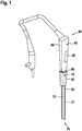
- Fig. 1 shows a schematic representation of an endoscope 60 with an endoscopic device in a perspective view.
- the endoscopic device forms the endoscope 60 completely.
- the endoscopic device could also be just a component, an assembly of the endoscope 60 or the like.
- the endoscopic device has a handle 62.
- the handle 62 has at least one handle 64.
- the handle 62 has a housing 66.
- the housing 66 is used to arrange further components of the endoscopic device.
- a deflection mechanism for deflecting the endoscope shaft 10 is arranged in the housing 66.
- the handle 62 has an operating element 68.
- the Operating element 68 is set up to operate a deflection of an endoscope shaft 10.
- the operating element 68 is operatively connected to the deflection mechanism.
- the endoscopic device has the endoscope shaft 10.
- the endoscope shaft 10 is flexible. Furthermore, the endoscope shaft 10 can be deflected at least in sections. The endoscope shaft 10 can be deflected by means of the deflection mechanism. The endoscope shaft 10 is operatively connected to the operating element 68 via the deflection mechanism.
- the endoscopic device has a tube 20.
- the tube 20 is a ventilation tube or an endotracheal tube.
- the tube 20 is adapted to be inserted into a windpipe.
- the tube 20 has a channel 70 which is set up to receive the endoscope shaft 10.
- the endoscope shaft 10 is at least partially insertable into the tube 20.
- the tube 20 has a proximal end section 92.
- the proximal end section 92 is designed as a hollow cylinder.
- the proximal end section 92 of the tube 20 is designed to accommodate the kink protection 12.
- the endoscopic device has at least one kink protection 12.
- the kink protection 12 is assigned to the endoscope shaft 10.
- the kink protection 12 is designed to prevent kinking and, in particular, damage to the endoscope shaft 10 associated therewith.
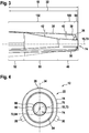
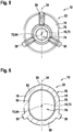
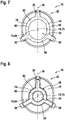
- Figs. 2 to 5 show a schematic representation of the kink protection 12 in different perspective views. Also show the Figures 6 to 8 a schematic representation of the kink protection 12 in different sectional views.
- the kink protection 12 has a base body 14.
- the base body 14 is free from rotational symmetry.
- the main body 14 has a main direction of extent 16.
- the main body 14 has a main extension 18 along the main extension direction 16.
- the base body 14 also has a recess 74.
- the recess 74 is designed to receive the endoscope shaft 10.
- a smallest inside diameter of the recess 74 corresponds at least to a largest outside diameter of the endoscope shaft 10.
- the base body 14 has a jacket 76.
- the jacket 76 extends over the main extension 18 of the base body 14.
- the jacket 76 has an outer surface 78.
- the jacket 76 also has an inner surface 80.
- the jacket 76 has a wall 82.
- the wall 82 is delimited by the inner surface 80 and the outer surface 78.
- the inner surface 80 delimits the recess 74.
- the wall 82 has a wall thickness.
- the wall thickness of the wall 80 is essentially constant along a main extension 18 of the base body 14.
- the base body 14 is at least partially elastic. In the present case, the base body 14 is formed at least to a large extent in one piece.
- the base body 14 has a Shore value of at least 40. Furthermore, the base body 14 has a Shore value of at most 80. In the present case, the base body 14 has a Shore value of at least substantially 62.
- the main body 14 consists at least partially of a medical plastic.
- the main body consists at least for the most part of a medical plastic.
- the medical plastic is designed to withstand autoclaving processes.
- the plastic is a thermoplastic elastomer.
- the thermoplastic elastomer is known under the brand name Mediprene.
- the base body 14 has at least one cylindrical section 48 (cf. Fig. 8 ).
- the cylindrical section 48 is a distal section of the base body 14.
- the recess 74 extends at least through the cylindrical section 48.
- the cylindrical section 48 has an outer diameter.
- the cylindrical section 48 has an inner diameter.
- the inner diameter corresponds to an outer diameter of the endoscope shaft 10.
- the cylindrical section has an axis 72 of rotational symmetry.
- the main direction of extent 16 of the base body is offset at least parallel to the rotational symmetry axis 72.
- the base body 14 has at least one further cylindrical section 52.
- the further cylindrical section 52 is a proximal section of the base body 14.
- the recess 74 extends through the further cylindrical section 52.
- the base body 14 has an annular cross section 54 (cf. Fig. 8 ).
- the further cylindrical section 52 has a further outer diameter.
- the further outside diameter of the cylindrical section 52 is larger than the outside diameter of the cylindrical section 48.
- the cylindrical section 52 has a further inside diameter.
- the further inside diameter corresponds at least essentially to an outside diameter of the handle 62.
- the further inside diameter of the further cylindrical section 52 is larger than the inside diameter of the cylindrical section 48.
- the further inside diameter of the further cylindrical section 52 is larger than the outside diameter of the cylindrical section 48.
- the base body 14 has an oval-ring-shaped cross section 58 (cf. Fig. 6 ).
- the further cylindrical section 52 has an axis of rotational symmetry 73.
- the main direction of extent 16 of the base body is identical to the rotational symmetry axis 73.
- the base body has at least one conical section 50.
- the conical section 50 is a central section of the base body 14.
- the recess 74 extends through the conical section 50.
- the conical section 50 is arranged between the cylindrical section 48 and the further cylindrical section 52.
- the conical section 50 connects the cylindrical section 48 and the further cylindrical section 52 to one another.
- the conical section 50 has an outer diameter.
- the outer diameter of the conical section increases along a main direction of extent of the base body from the outer diameter of the cylindrical section 48 to the further outer radius of the further cylindrical section 52.
- the conical section 50 has an inner radius.
- the inner radius of the conical section 50 increases from the inner radius of the cylindrical section 48 to the further inner radius of the further cylindrical section 48. In the present case, the diameter increases continuously. Alternatively, the diameter could be increased gradually.
- the base body 14 has an oval-ring-shaped cross section 56 (cf. Fig. 6 ).
- the kink protection 12 has at least one connecting element 84 (cf. Fig. 4 ).
- the connecting element 84 is arranged on the base body 14.
- the connecting element 84 is in section 52 arranged.
- the connecting element 84 is arranged on the inner surface 80.
- the connecting element 84 is designed as an annular lip.
- the connecting element 84 is formed in one piece with the base body 14. If the kink protection 12 is pushed onto the endoscope shaft 10 up to the handle 62, the connecting element 84 establishes a connection between the kink protection 12 and the handle 62.
- the handle 62 has a connecting element 86 which corresponds to the connecting element 84 and which engages behind the connecting element 84 during a connection.
- the kink protection 12 has at least one locking element 88 (cf. Fig. 4 ).
- the kink protection has at least one further locking element 90, which is arranged at a distance from the locking element 88. Only one locking element 88 is described in more detail below. The description can be transferred to the further locking element 90.
- the locking element 88 is arranged on the base body 14.
- the locking element 88 is arranged in section 48.
- the locking element 88 is arranged on the inner surface 80.
- the locking element 88 is designed as an annular lip.
- the locking element 88 is formed in one piece with the base body 14. If the kink protection 12 is pushed onto the endoscope shaft 10, the locking element 88 is clamped with the endoscope shaft 10.
- the kink protection 12 has at least one quick connector 22 for a releasable connection to the tube 20.
- the quick connector 22 is set up for a form-fitting and / or force-fitting connection with the tube 20.
- the quick connector 22 has at least one fin 26.
- the fin 26 is arranged so as to be at least substantially perpendicular to the base body 14.
- the fin 26 is perpendicular to the jacket 76 of the base body 14.
- the fin 26 is set up to bend laterally when contact is made by the tube 20.
- the fin 26 has an extension 32 along the main extension direction 16 of the base body 14, which extends at least over 50% of the main extension 18 of the base body 14 (cf. Fig. 3 ). In the present case, the extension 18 of the fin 26 even extends over at least 80% of the main extension 18 of the base body 14.
- a main extension plane 34 of the fin 26 is oriented at least substantially parallel to the main extension direction 16 of the base body 14. More precisely, the main extension direction 16 of the base body 14 lies in the main extension plane 34 of the fin 26.
- the fin 26 has at least one outer edge 36 facing away from the base body 14.
- An angle 38, 40, 42 of the outer edge 36 relative to the main direction of extent 16 decreases along the main extent 18 of the base body 14, in particular in the proximal direction.
- the angle 38, 40, 42 decreases in steps.
- the angle 38, 40, 42 could also decrease continuously.
- the fin 26 has at least a first section 98.
- the first section 98 extends within a region of the cylindrical section 48 of the base body 14. In the first section 98, the outer edge 36 has an angle 38 relative to the main direction of extent 16 of at most 80 °.
- the fin 26 has a second section 100.
- the second section 100 extends in a region of the cylindrical section 48 of the base body 14. In the second section 100, the outer edge 36 of the fin 26 has an angle 40 relative to the main direction of extent 16 of at most 10 °.
- the fin 26 has a third section 102.
- the third section 102 extends over an area of the cylindrical section 48, the conical section 50 and the cylindrical section 52 of the base body 14.
- the outer edge 36 of the fin 26 has an angle 38, 40, 42 relative to the main direction of extent 16 of at most 5 °.
- the second section 100 is arranged behind the first section 98 when viewed in the proximal direction.
- the third section 102 is arranged behind the second section 100, viewed in the proximal direction.
- the second section 100 connects the first section 98 and the third section 102 to one another.
- the fin 26 has a height 44 relative to the base body 14. Furthermore, the fin 26 has a thickness 46. The thickness 46 is measured perpendicular to the main extension plane 34 of the fin 26. The height 44 of the fin 26 corresponds to at least double the thickness 46 of the fin 26, in particular in the first section 98 of the fin 26. Due to different sections of the base body 14 and the fin 26, a relative height 44 of the fin 26, viewed in the proximal direction, increases relative to Base body 14 measured down.
- the fin 26 is at least partially formed from an elastic material.
- the elastic material has a Shore value of at least 40. Furthermore, the elastic material has a Shore value of at most 80. In the present case, the elastic material has a Shore value of at least substantially 62.
- the material is a medical plastic.
- the material is a thermoplastic elastomer. In the present case, the material is known under the brand name Mediprene.
- the fin 26 is formed in one piece with the base body 14.
- the fin 26 is made of the same material as the base body 14.
- the fin 26 and the base body 14 form an injection-molded assembly.
- the fins 26, 28, 30 and the base body 14 could be manufactured separately from one another.
- the fin 26 and the base body 14 could then be connected to one another.
- the fin 26 and the base body 14 could be welded or glued to one another.
- a production of the base body and the fin 26 by a multi-component injection molding is conceivable.
- the quick connector 22 has at least one further fin 28.
- the further fin 28 is at least substantially identical to the fin 26.
- the quick connector 22 has at least one additional fin 30.
- the additional fin 30 is at least substantially identical to the fin 26.
- the quick connector 22 accordingly has a total of three fins 26, 28, 30.
- the quick connector 22 could comprise a number of fins 26, 28, 30 that differs from the number shown here, in order to vary a clamping force, for example.
- the fins 26, 28, 30 are arranged rotationally symmetrically to one another on the base body 14.
- the fins 26, 28, 30 are arranged on the base body 14 in accordance with a three-fold rotational symmetry.
- the degree of rotational symmetry can be varied via the number of fins.
- a rotational symmetry axis 94 of the rotational symmetry of the fins 26, 28, 30 is different from the rotational symmetry axis 73.
- the rotational symmetry axis 94 is identical to the rotational symmetry axis 72.
- the rotational symmetry axis 94 of the fins 26, 28, 30 is parallel to the main direction of extent 16 of the base body 14
- the axis of rotational symmetry 94 of the fins 26, 28, 30 is offset parallel to the main direction of extent 16 of the base body 14.
- the anti-kink protection 12 itself has no rotational symmetry as a whole.
- the kink protection 12 has a mirror symmetry.
- a mirror plane of the mirror symmetry of the kink protection 12 corresponds to the main extension plane 34 of the fin 26.
- Fig. 9 a schematic flow chart of a method for producing the endoscopic device is shown.
- the method comprises at least one method step 120.
- method step 120 a shape is generated which corresponds to a negative of the desired kink protection 12.
- the method comprises at least one further method step 122.
- the material is liquefied.
- the material is poured into the mold.
- the material is hardened in the mold.
- the kink protection 12 is formed.
- the method comprises a further method step 124.
- the kink protection 12 is removed from the mold. The kink protection 12 is then ready for use.
- Fig 10 a schematic flow chart of an exemplary method for assembling and / or disassembling the kink protection 12 is shown.
- the method comprises at least one method step 126.
- the endoscope shaft 10 is inserted into the recess 74 of the kink protection 12.
- the kink protection 12 is guided in the proximal direction along the endoscope shaft 10.
- the kink protection 12 is guided along the endoscope shaft 10 until the handle 62 is reached. Furthermore, the kink protection 12 is connected to the handle 62.
- the method comprises at least one further method step 128.
- the tube 20 is guided onto the endoscope shaft 10.
- the tube 20 is guided onto the endoscope shaft 10 until the proximal end section of the tube 20 comes into contact with the kink protection 12.
- the method comprises at least one further method step 130.
- the tube 20 is connected to the kink protection 12 by means of the quick connector 22.
- the proximal end section 92 of the tube 20 is guided over the fins 26, 28, 30 of the kink protection 12.
- the proximal end section 92 of the tube 20 presses the fins 26, 28, 30 to the side, so that they deform laterally and jam within the end section.
- the fins 26, 28, 30 clamp the tube 20 from the inside with the kink protection 12.
- the tube 22 can be dismantled in that the tube 20 is subjected to a force in the distal direction which is greater than the clamping force acting on the tube 20 by the fins 26, 28, 30.
- the tube 20 can be rotated relative to the kink protection 12 in order to overcome static friction of the fins 26, 28, 30 laterally and thus to reduce a clamping force acting on the inner wall of the tube.
Landscapes
- Health & Medical Sciences (AREA)
- Life Sciences & Earth Sciences (AREA)
- Surgery (AREA)
- Engineering & Computer Science (AREA)
- Biomedical Technology (AREA)
- Veterinary Medicine (AREA)
- Public Health (AREA)
- General Health & Medical Sciences (AREA)
- Animal Behavior & Ethology (AREA)
- Heart & Thoracic Surgery (AREA)
- Medical Informatics (AREA)
- Biophysics (AREA)
- Physics & Mathematics (AREA)
- Molecular Biology (AREA)
- Pathology (AREA)
- Optics & Photonics (AREA)
- Nuclear Medicine, Radiotherapy & Molecular Imaging (AREA)
- Radiology & Medical Imaging (AREA)
- Pulmonology (AREA)
- Mechanical Engineering (AREA)
- Emergency Medicine (AREA)
- Anesthesiology (AREA)
- Hematology (AREA)
- Otolaryngology (AREA)
- Physiology (AREA)
- Endoscopes (AREA)
Abstract
Die Erfindung geht aus von einer endoskopischen Vorrichtung mit wenigstens einem flexiblen Endoskopschaft (10) und mit wenigstens einem den Endoskopschaft (10) zugeordneten Knickschutz (12), welcher wenigstens einen, zumindest abschnittsweise konisch und/oder zylindrisch ausgebildeten Grundkörper (14), der eine Haupterstreckungsrichtung (16) sowie eine Haupterstreckung (18) entlang der Haupterstreckungsrichtung (16) aufweist, umfasst, und der Knickschutz (12) wenigstens einen zu einer wahlweisen Verbindung mit einem Tubus (20) eingerichteten Schnellverbinder (22) umfasst, welcher wenigstens eine, zumindest im Wesentlichen senkrecht auf dem Grundkörper (14) stehende Finne (26, 28, 30) aufweist.The invention is based on an endoscopic device with at least one flexible endoscope shaft (10) and with at least one kink protection (12) assigned to the endoscope shaft (10), which has at least one, at least partially conical and / or cylindrical base body (14), the one Main extension direction (16) and a main extension (18) along the main extension direction (16) comprises, and the kink protection (12) comprises at least one quick connector (22) which is set up for an optional connection to a tube (20) and which has at least one, at least has fin (26, 28, 30) which are essentially perpendicular to the base body (14).
Es wird vorgeschlagen, dass die Finne (26, 28, 30) eine Erstreckung (32) aufweist, welche sich entlang der Haupterstreckungsrichtung (16) des Grundkörpers (14) wenigstens über 50 % der Haupterstreckung (18) des Grundkörpers (14) erstreckt.

Description
Die Erfindung betrifft eine endoskopische Vorrichtung gemäß dem Oberbegriff des Anspruch 1.The invention relates to an endoscopic device according to the preamble of claim 1.
Aus der
Die Aufgabe der Erfindung besteht insbesondere darin, eine gattungsgemäße Vorrichtung mit verbesserten Eigenschaften hinsichtlich Sicherheit bereitzustellen. Die Aufgabe wird erfindungsgemäß durch die Merkmale des Patentanspruchs 1 gelöst, während vorteilhafte Ausgestaltungen und Weiterbildungen der Erfindung den Unteransprüchen entnommen werden können.The object of the invention is in particular to provide a device of the generic type with improved properties with regard to safety. The object is achieved according to the invention by the features of claim 1, while advantageous configurations and developments of the invention can be found in the subclaims.
Die Erfindung geht aus von einer endoskopischen Vorrichtung mit wenigstens einem flexiblen Endoskopschaft und mit wenigstens einem den Endoskopschaft zugeordneten Knickschutz, welcher zu einer wahlweisen Verbindung des Knickschutzes mit einem Tubus eingerichtet ist, und welcher wenigstens einen, zumindest abschnittsweise konisch und/oder zylindrisch ausgebildeten Grundkörper, der eine Haupterstreckungsrichtung sowie eine Haupterstreckung entlang der Haupterstreckungsrichtung aufweist, umfasst, und der Knickschutz zur Verbindung mit dem Tubus wenigstens einen Schnellverbinder umfasst, welcher wenigstens eine zumindest im Wesentlichen senkrecht auf dem Grundkörper stehende Finne aufweist.The invention is based on an endoscopic device with at least one flexible endoscope shaft and with at least one kink protection assigned to the endoscope shaft, which is set up for an optional connection of the kink protection with a tube, and which has at least one, at least partially conical and / or cylindrical base body, which has a main direction of extent and a main extent along the main direction of extent, and the kink protection for connection to the tube at least one quick connector comprises, which has at least one fin that is at least substantially perpendicular to the base body.
Es wird vorgeschlagen, dass die Finne eine Erstreckung aufweist, welche sich entlang der Haupterstreckungsrichtung des Grundkörpers über zumindest 50 %, insbesondere über zumindest 60%, vorzugsweise über zumindest 70 % und besonders bevorzugt über zumindest 80 %, der Haupterstreckung des Grundkörpers erstreckt.It is proposed that the fin have an extension which extends along the main direction of extent of the base body over at least 50%, in particular over at least 60%, preferably over at least 70% and particularly preferably over at least 80% of the main extent of the base body.
Hierdurch kann vorteilhaft ein Halt des Tubus an dem Knickschutz verbessert werden, wodurch ein versehentliches ablösen vermieden und eine Sicherheit erhöht werden kann. Weiter vorteilhaft kann eine Sicherheit beim Entfernen des Tubus verbessert werden, da der Knickschutz aufgrund der vorliegenden Ausgestaltung nicht plötzlich seine Klemmkraft verliert, sondern gleichmäßig und langsam gelöst werden kann. Ferner vorteilhaft erzielt der Schnellverbinder auch eine sichere Verbindung auch mit Tuben welche beispielsweise aufgrund von Herstellungstoleranzen verschiedene Innendurchmesser aufweisen.As a result, the hold of the tube on the kink protection can advantageously be improved, as a result of which accidental detachment can be avoided and safety can be increased. Safety when removing the tube can further advantageously be improved, since the kink protection does not suddenly lose its clamping force due to the present embodiment, but can be released evenly and slowly. Furthermore, the quick connector advantageously achieves a secure connection even with tubes which have different inside diameters, for example due to manufacturing tolerances.
Unter einer "endoskopischen Vorrichtung" soll insbesondere ein, vorzugsweise funktionsfähiger Bestandteil, insbesondere eine Unterbaugruppe und/oder eine Konstruktions- und/oder eine Funktionskomponente eines Endoskops verstanden werden. Vorzugsweise kann die endoskopische Vorrichtung das Endoskop zumindest teilweise, vorzugsweise zumindest zu einem Großteil und besonders bevorzugt vollständig ausbilden. In etwa ist die endoskopische Vorrichtung dazu eingerichtet, zumindest teilweise und vorzugsweise zumindest zu einem Großteil in eine insbesondere künstliche und/oder natürliche Kavität, insbesondere Körperkavität, eingeführt zu werden und zwar insbesondere um diese zu begutachten. Bei der endoskopischen Vorrichtung kann es sich um eine medizinische und/oder industrielle endoskopische Vorrichtung handeln. Unter "eingerichtet" soll insbesondere speziell programmiert, ausgebildet, ausgelegt und/oder ausgestattet verstanden werden. Darunter, dass ein Bauteil zu einer bestimmten Funktion eingerichtet ist, soll insbesondere verstanden werden, dass das Bauteil diese bestimmte Funktion in zumindest einem Anwendungs- und/oder Betriebszustand erfüllt und/oder ausführt. Unter einem "Endoskopschaft" soll insbesondere ein länglicher Teil eines Endoskops verstanden werden, welcher in etwa dazu ausgebildet ist, in eine insbesondere künstliche und/oder natürliche Kavität, insbesondere Körperkavität, eingeführt zu werden. Unter einem "länglichen Teil" soll insbesondere ein Bauteil verstanden werden, dessen Haupterstreckung zumindest um einen Faktor fünf, vorzugsweise zumindest um einen Faktor zehn und besonders bevorzugt zumindest um einen Faktor zwanzig größer ist als eine größte Erstreckung des Bauteils senkrecht zu dessen Haupterstreckung, also insbesondere einem Durchmesser des Bauteils. Unter einer "Haupterstreckung" eines Bauteils, soll insbesondere dessen längste Erstreckung entlang dessen Haupterstreckungsrichtung verstanden werden. Unter einer "Haupterstreckungsrichtung" eines Bauteils soll insbesondere eine Richtung verstanden werden, welche parallel zu einer längsten Kante eines kleinsten gedachten Quaders verläuft, welcher das Bauteil gerade noch vollständig umschließt und welche vorzugsweise durch ein geometrischen Mittelpunkt und/oder durch einen Massenmittelpunkt des Bauteils verläuft. Der Endoskopschaft weist insbesondere einen distalen Endabschnitt und einen proximalen Endabschnitt auf. Unter einem "Endabschnitt" eines Bauteils soll insbesondere ein Abschnitt verstanden werden, welcher sich ausgehend von einem Ende des Bauteils zur Mitte des Bauteils hin, um höchstens 10 cm, vorzugsweise um höchstens 5 cm und besonders bevorzugt um höchstens 3 cm, erstreckt. Unter einem "distalen Endabschnitt" eines Bauteils soll insbesondere ein Endabschnitt verstanden werden, welcher sich ausgehend von einem distalen Ende des Bauteils in proximaler Richtung erstreckt. Unter einem "proximalen Endabschnitt" eines Bauteils soll insbesondere ein Endabschnitt verstanden werden, welcher sich ausgehend von einem proximalen Ende des Bauteils in distaler Richtung erstreckt. Unter "distal" soll insbesondere bei einer Bedienung einem Patienten zugewandt und/oder einem Bediener abgewandt verstanden werden. Insbesondere ist proximal das Gegenteil von distal. Unter "proximal" soll insbesondere bei einer Bedienung einem Patienten abgewandt und/oder einem Bediener zugewandt verstanden werden. Ferner weist die endoskopische Vorrichtung insbesondere zumindest eine Handhabe auf. Die Handhabe ist in etwa am proximalen Endabschnitt des Endoskopschafts angeordnet. Die Handhabe ist insbesondere für eine manuelle Bedienung der endoskopischen Vorrichtung ausgebildet. Die Handhabe umfasst in etwa zumindest einen Handgriff und/oder zumindest ein Bedienelement, wie beispielsweise ein Schalter, Knopf oder dergleichen, welches vorzugsweise am Handgriff angeordnet ist. Unter einem "Knickschutz" soll insbesondere ein Bauteil verstanden werden, welche dazu eingerichtet ist, ein Abknicken des Endoskopschafts zu vermeiden und zwar insbesondere am proximalen Endabschnitt des Endoskopschafts, vorzugsweise im Übergangsbereich des Endoskopschafts zur Handhabe. Insbesondere ist der Knickschutz als Ganzes betrachtet frei von einer Drehsymmetrie. Vorzugsweise weist der Knickschutz eine Spiegelsymmetrie auf, wobei eine Spiegelebene der Spiegelsymmetrie wenigstens einer Haupterstreckungsebene einer Finne entspricht. Unter einer "Haupterstreckungsebene" eines Bauteils soll insbesondere eine Ebene verstanden werden, welche parallel zu einer größten Seitenfläche eines kleinsten gedachten Quaders ist, welcher das Bauteil gerade noch vollständig umschließt, und insbesondere durch den Mittelpunkt des Quaders verläuft. Bei dem Tubus handelt es sich insbesondere um einen Beatmungstubus oder Endotrachealtubus, welcher dazu eingerichtet ist, in eine Luftröhre eingeführt zu werden. Der Tubus weist insbesondere einen Kanal auf, welcher dazu eingerichtet ist, den Endoskopschaft aufzunehmen. Unter einem "Schnellverbinder" soll insbesondere ein Bauteil verstanden werden, welches dazu eingerichtet ist, wenigstens zwei Bauteile lösbar und werkzeuglos miteinander zu verbinden. Vorzugsweise ist der Schnellverbinder zur Ausbildung einer kraft- und/oder formschlüssigen Verbindung vorgesehen, wie beispielsweise einer Klemmverbindung. Unter "zumindest im Wesentlichen senkrecht" soll insbesondere eine Ausrichtung einer Richtung relativ zu einer Bezugsrichtung, insbesondere in einer Ebene, verstanden werden, wobei die Richtung und die Bezugsrichtung einen Winkel von 90°, insbesondere unter Berücksichtigung einer maximalen Abweichung von kleiner als 8°, vorteilhaft von kleiner als 5° und besonders vorteilhaft von kleiner als 2° einschließt.An “endoscopic device” is to be understood as meaning, in particular, a preferably functional component, in particular a subassembly and / or a construction and / or a functional component of an endoscope. The endoscopic device can preferably form the endoscope at least partially, preferably at least to a large extent and particularly preferably completely. The endoscopic device is approximately set up to be introduced at least partially and preferably at least for the most part into an in particular artificial and / or natural cavity, in particular a body cavity, in particular in order to examine it. The endoscopic device can be a medical and / or industrial endoscopic device. The term “set up” is to be understood in particular as specifically programmed, designed, designed and / or equipped. The fact that a component is set up for a specific function should be understood in particular to mean that the component fulfills and / or executes this specific function in at least one application and / or operating state. An “endoscope shaft” is to be understood in particular as an elongated part of an endoscope which is approximately designed to be inserted into an in particular artificial and / or natural cavity, in particular a body cavity. An "elongated part" should in particular be a component be understood, the main extent of which is at least a factor of five, preferably at least a factor of ten and particularly preferably at least a factor of twenty larger than a largest extent of the component perpendicular to its main extent, so in particular a diameter of the component. A “main extension” of a component is to be understood in particular to mean its longest extension along its main direction of extension. A "main direction of extent" of a component is to be understood in particular as a direction which runs parallel to a longest edge of a smallest imaginary cuboid which just completely surrounds the component and which preferably runs through a geometric center and / or through a center of mass of the component. The endoscope shaft in particular has a distal end section and a proximal end section. An "end section" of a component is to be understood in particular as a section which, starting from one end of the component to the center of the component, extends by at most 10 cm, preferably by at most 5 cm and particularly preferably by at most 3 cm. A “distal end section” of a component is to be understood in particular as an end section which, starting from a distal end of the component, extends in the proximal direction. A “proximal end section” of a component is to be understood in particular as an end section which, starting from a proximal end of the component, extends in the distal direction. “Distal” is to be understood to mean facing a patient and / or facing away from an operator in particular during operation. In particular, proximal is the opposite of distal. “Proximal” is to be understood to mean facing away from a patient and / or facing an operator during operation. Furthermore, the endoscopic device has in particular at least one handle. The handle is arranged approximately on the proximal end section of the endoscope shaft. The handle is designed in particular for manual operation of the endoscopic device. The handle includes approximately at least one handle and / or at least one operating element, such as a switch, button or the like, which is preferably arranged on the handle. A "kink protection" is to be understood in particular as a component which is designed to prevent the endoscope shaft from kinking, in particular at the proximal end section of the endoscope shaft, preferably in the transition area of the endoscope shaft to the handle. In particular, the kink protection is considered as a whole free of one Rotational symmetry. The kink protection preferably has a mirror symmetry, wherein a mirror plane of the mirror symmetry corresponds to at least one main plane of extent of a fin. A “main extension plane” of a component is to be understood in particular as a plane which is parallel to a largest side surface of a smallest imaginary cuboid, which just completely encloses the component, and in particular runs through the center of the cuboid. The tube is in particular a ventilation tube or endotracheal tube which is designed to be inserted into a trachea. The tube has, in particular, a channel which is set up to receive the endoscope shaft. A "quick connector" is to be understood as meaning, in particular, a component which is designed to connect at least two components to one another in a detachable manner and without tools. The quick connector is preferably provided to form a non-positive and / or positive connection, such as a clamp connection. "At least substantially perpendicular" is to be understood as meaning, in particular, an alignment of a direction relative to a reference direction, in particular in a plane, the direction and the reference direction at an angle of 90 °, in particular taking into account a maximum deviation of less than 8 °, advantageously of less than 5 ° and particularly advantageously of less than 2 °.
Es wäre denkbar, dass sich die Finne gewindeartig um den Grundkörper windet. Um insbesondere jedoch ein sicheres und leicht gängiges Abziehen des Tubus zu erzielen wird vorgeschlagen, dass eine Haupterstreckungsebene der Finne zumindest im Wesentlichen parallel zu Haupterstreckungsrichtung des Grundkörpers ausgerichtet ist. Unter "zumindest im Wesentlichen parallel" soll insbesondere eine Ausrichtung einer Richtung relativ zu einer Bezugsrichtung, insbesondere in einer Ebene, verstanden werden, wobei die Richtung und die Bezugsrichtung einen Winkel von 0°, insbesondere unter Berücksichtigung einer maximalen Abweichung von kleiner als 8°, vorteilhaft von kleiner als 5° und besonders vorteilhaft von kleiner als 2° einschließt.It would be conceivable that the fin winds around the base body like a thread. In order, however, in particular to achieve safe and easy removal of the tube, it is proposed that a main plane of extent of the fin is at least substantially parallel to the main direction of extent of the base body. "At least essentially parallel" is to be understood as meaning, in particular, an alignment of a direction relative to a reference direction, in particular in a plane, the direction and the reference direction at an angle of 0 °, in particular taking into account a maximum deviation of less than 8 °, advantageously of less than 5 ° and particularly advantageously of less than 2 °.
Ferner wird vorgeschlagen, dass die Finne wenigstens eine dem Grundkörper abgewandte Außenkante aufweist, wobei ein Winkel der Außenkante relativ zur Haupterstreckungsrichtung entlang der Haupterstreckung des Grundkörpers, insbesondere in proximaler Richtung hin, abnimmt. Es kann vorteilhaft eine Sicherheit weiter verbessert werden, da ein Tubus entlang der Finne bei einem Einführvorgang zentriert werden kann. Weiter vorteilhaft kann ein leicht gängiges Verbinden eines Tubus mit dem Knickschutz erreicht werden. Der Winkel kann dabei kontinuierlich und/oder Stufenweise abnehmen. Insbesondere weist die Finne verschiedene Abschnitte auf, in welchen der Winkel stufenweise abnimmt. Insbesondere beträgt der Winkel in einem ersten Abschnitt der Finne höchstens 80°, in wenigstens einem zweiten Abschnitt der Finne höchstens 10° und/oder in wenigstens einem dritten Abschnitt der Finne höchstens 5°.It is further proposed that the fin has at least one outer edge facing away from the base body, an angle of the outer edge decreasing relative to the main direction of extent along the main extent of the base body, in particular in the proximal direction. It can be beneficial a security can be further improved since a tube can be centered along the fin during an insertion process. It is also advantageously possible to easily connect a tube to the kink protection. The angle can decrease continuously and / or in steps. In particular, the fin has different sections in which the angle gradually decreases. In particular, the angle is at most 80 ° in a first section of the fin, at most 10 ° in at least a second section of the fin and / or at most 5 ° in at least a third section of the fin.
Es wird vorgeschlagen, dass die Finne dazu eingerichtet ist, sich bei einer Kontaktierung, insbesondere mit dem Tubus, seitlich zu verbiegen. Es kann vorteilhaft eine Sicherheit weiter verbessert werden. Insbesondere kann ein vorteilhaftes Verklemmen eines Tubus am Knickschutz erzielt werden. Darunter, dass die Finne dazu eingerichtet ist, sich seitlich zu verbergen, soll insbesondere versstanden werden, dass sich die Finnen relativ zu ihrer Haupterstreckungsebene betrachtet aus dieser heraus konvex und/oder konkav verformt.It is proposed that the fin is set up to bend laterally when making contact, in particular with the tube. Security can advantageously be further improved. In particular, an advantageous clamping of a tube on the kink protection can be achieved. The fact that the fin is set up to hide itself laterally should be understood in particular to mean that the fins are deformed convexly and / or concavely out of this plane relative to their main extension plane.
Es wird vorgeschlagen, dass die Finne eine maximale Höhe relativ zum Grundkörper aufweist, welche wenigstens einer doppelten Dicke der Finne entspricht. Es kann vorteilhaft eine Sicherheit weiter verbessert werden. Insbesondere kann ein besonders leichtes Auslenken der Finne erzielt werden. Die Dicke ist dabei insbesondere senkrecht zur Haupterstreckungsebene der Finne gemessen.It is proposed that the fin has a maximum height relative to the base body which corresponds to at least twice the thickness of the fin. Security can advantageously be further improved. In particular, a particularly easy deflection of the fin can be achieved. The thickness is measured particularly perpendicular to the main extension plane of the fin.
Es wird vorgeschlagen, dass die Finne wenigstens teilweise, vorzugsweise zumindest zu einem Großteil und besonders bevorzugt vollständig, elastisch ausgebildet ist. Es kann vorteilhaft eine Sicherheit bei einer Montage und/oder Demontage des Tubus weiter verbessert werden. Unter einem "elastischen Bauteil" soll insbesondere ein Bauteil verstanden werden, welches bei einer Verformung aus einer Grundstellung heraus wieder von alleine in die Grundstellung strebt.It is proposed that the fin is at least partially, preferably at least to a large extent and particularly preferably completely, elastic. It is advantageous to further improve safety during assembly and / or disassembly of the tube. An “elastic component” is to be understood in particular as a component which, when deformed from a basic position, tends to return to the basic position by itself.
Es wird weiter vorgeschlagen, dass die Finne wenigstens teilweise, vorzugsweise zumindest zu einem Großteil und besonders bevorzugt vollständig, aus einem Material besteht, welches einen Shorewert von wenigstens 40, insbesondere wenigstens 50, vorzugsweise wenigstens 60, und/oder höchstens 90, insbesondere höchstens 80, vorzugsweise höchstens 70 aufweist. Hierdurch kann vorteilhaft eine Sicherheit weiter verbessert werden. Insbesondere kann hierdurch ein guter Kompromiss zwischen leichter Montage bzw. Demontage und sicherem Halt des Tubus an dem Knickschutz gefunden werden. Unter dem Ausdruck "zumindest zu einem Großteil" soll dabei insbesondere zumindest zu 55 %, vorzugsweiser zumindest zu 65 %, bevorzugt zumindest zu 75 %, besonders bevorzugt zumindest zu 85 % und ganz besonders bevorzugt zumindest zu 95 %, sowie vorteilhaft vollständig verstanden werden und zwar insbesondere mit Bezug auf ein Volumen und/oder eine Masse eines Bauteils. Besonders bevorzugt beträgt der Shorewert zumindest im Wesentlichen 65. Unter "zumindest im Wesentlichen" soll insbesondere eine maximale Abweichung von höchstens 10 %, vorzugsweise von höchstens 5 % und besonders bevorzugt von höchstens 2 % umfassend verstanden werden.It is further proposed that the fin consists at least partially, preferably at least to a large extent and particularly preferably completely, of a material which has a Shore value of at least 40, in particular at least 50, preferably at least 60, and / or at most 90, in particular at most 80 , preferably at most 70. As a result, security can advantageously be further improved. In particular, this enables a good compromise between lighter Assembly or disassembly and a secure hold of the tube can be found on the kink protection. The expression "at least to a large extent" should be understood to mean in particular at least 55%, preferably at least 65%, preferably at least 75%, particularly preferably at least 85% and very particularly preferably at least 95%, and advantageously completely in particular with reference to a volume and / or a mass of a component. The Shore value is particularly preferably at least essentially 65. “At least essentially” should be understood to include, in particular, a maximum deviation of at most 10%, preferably of at most 5% and particularly preferably of at most 2%.
Es wird ferner vorgeschlagen, dass die Finne wenigstens teilweise, vorzugsweise zumindest zu einem Großteil und besonders bevorzugt vollständig, aus einem Material, insbesondere das vorbenannte Material besteht, bei welchem es sich um ein thermoplastisches Elastomer handelt. Insbesondere kann eine Sicherheit weiter verbessert werden. Das thermoplastische Elastomer ist vorzugsweise das thermoplastische Elastomer, welches unter dem Markennamen Mediprene bekannt ist.It is further proposed that the fin consists at least partially, preferably at least to a large extent and particularly preferably completely, from a material, in particular the aforementioned material, which is a thermoplastic elastomer. In particular, security can be further improved. The thermoplastic elastomer is preferably the thermoplastic elastomer known under the brand name Mediprene.
Des Weiteren wir vorgeschlagen, dass der Grundkörper zumindest einen konischen Abschnitt und wenigstens einen zylindrischen Abschnitt aufweist. Insbesondere kann eine Sicherheit weiter verbessert werden. Insbesondere kann vorteilhaft eine Klemmwirkung der Finne zwischen Tubus und Grundkörper verbessert werden. Insbesondere kann der Grundkörper zumindest zwei zylindrische Abschnitte aufweisen, welche vorzugsweise durch wenigstens einen konischen Abschnitt miteinander verbunden sind.Furthermore, we propose that the base body have at least one conical section and at least one cylindrical section. In particular, security can be further improved. In particular, a clamping effect of the fin between the tube and the base body can advantageously be improved. In particular, the base body can have at least two cylindrical sections, which are preferably connected to one another by at least one conical section.
Der Grundkörper weist wenigstens einen Abschnitt, insbesondere einen zylindrischen Abschnitt auf, in welchem der Grundkörper senkrecht zu dessen Haupterstreckungsrichtung geschnitten wenigstens eine kreisringförmige Form Querschnitt aufweist. Um insbesondere einen sicheren Halt zu ermöglichen und eine Orientierung des Tubus relativ zum Knickschutz klar zu definieren, wird vorgeschlagen, dass der Grundkörper senkrecht zu dessen Haupterstreckungsrichtung geschnitten wenigstens abschnittsweise einen von einer kreisringförmigen Form abweichenden Querschnitt aufweist. Insbesondere weist wenigstens ein konischer Abschnitt des Grundkörpers senkrecht zu dessen Haupterstreckungsrichtung geschnitten wenigstens einen von einer Kreisringform abweichenden Querschnitt auf. Vorzugsweise weist der Grundkörper im konischen Abschnitt senkrecht zu dessen Haupterstreckungsrichtung geschnitten wenigstens einen ovalringförmigen Querschnitt auf. Vorzugsweise ist der Grundkörper frei von einer Drehsymmetrie. Denkbar ist, dass einzelne Abschnitte, wie beispielsweise ein konischer Abschnitt und/oder ein kreisringförmiger Abschnitt eine Drehsymmetrie aufweisen, diese jedoch entlang ihrer jeweiligen Drehsymmetrieachsen zueinander versetzt angeordnet sind, sodass der die Abschnitte aufweisende Grundkörper insgesamt von einer Drehsymmetrie frei ist. Alternativ könnte der Grundkörper eine endliche Drehsymmetrie auf. Vorzugsweise weist der Grundkörper eine n-zählige Drehsymmetrie auf, wobei n eine von unendlich verschiedener Zahl ist. Besonders bevorzugt ist n eine gerade Zahl und beträgt ganz besonders bevorzugt den Wert zwei.The base body has at least one section, in particular a cylindrical section, in which the base body, cut perpendicular to its main direction of extent, has at least one circular cross-section. In order to enable in particular a secure hold and to clearly define an orientation of the tube relative to the kink protection, it is proposed that the base body, cut perpendicular to its main direction of extent, at least in sections have a cross section deviating from a circular shape. In particular, at least one conical section of the main body, cut perpendicular to its main direction of extent, has at least one cross section deviating from a circular ring shape. Preferably, the Base body cut in the conical section perpendicular to its main direction of extent at least one oval-ring-shaped cross section. The base body is preferably free of rotational symmetry. It is conceivable that individual sections, such as a conical section and / or a circular ring-shaped section, have rotational symmetry, but these are arranged offset from one another along their respective rotational symmetry axes so that the base body having the sections is free of rotational symmetry as a whole. Alternatively, the base body could have a finite rotational symmetry. The base body preferably has n-fold rotational symmetry, where n is a number that is infinitely different. Particularly preferably, n is an even number and is very particularly preferably the value two.
Es wird vorgeschlagen, dass die Finne einstückig mit dem Grundkörper ausgebildet ist. Hierdurch kann eine Sicherheit weiter verbessert werden. Insbesondere kann vermieden werden, dass sich einzelne Finnen vom Grundkörper bei einer Benutzung lösen und zu einem ungewollten aufheben der Verbindung des Tubus mit dem Knickschutz führen könnten. Unter "einstückig" soll insbesondere zumindest stoffschlüssig verbunden, beispielsweise durch einen Schweißprozess, einen Klebeprozess, einen Anspritzprozess und/oder einen anderen, dem Fachmann als sinnvoll erscheinenden Prozess, und/oder vorteilhaft in einem Stück geformt verstanden werden, wie beispielsweise durch eine Herstellung aus einem Guss und/oder durch eine Herstellung in einem Ein- oder Mehrkomponentenspritzverfahren und vorteilhaft aus einem einzelnen Rohling.It is proposed that the fin be designed in one piece with the base body. As a result, security can be further improved. In particular, it can be avoided that individual fins become detached from the base body during use and could lead to an unintentional breaking of the connection between the tube and the kink protection. "In one piece" is to be understood in particular to be at least cohesively connected, for example by a welding process, an adhesive process, an injection molding process and / or another process that appears sensible to a person skilled in the art, and / or advantageously formed in one piece, for example by a production from a casting and / or by production in a single or multi-component injection molding process and advantageously from a single blank.
Es wird vorgeschlagen, dass der Schnellverbinder wenigstens eine weitere Finne aufweist, welche im Wesentlichen identisch zu der Finne ausgebildet ist. Hierdurch kann vorteilhaft eine Sicherheit weiter verbessert werden. Weiter vorteilhaft kann eine Klemmkraft erhöht werden. Die Finne und die weitere Finne sind insbesondere zueinander in Umfangsrichtung um den Grundkörper beabstandet angeordnet. Insbesondere weist der Schnellverbinder eine Anzahl von m Finnen auf, wobei insbesondere gelten soll m= n+1 und somit vorzugsweise eine ungerade Zahl ist. Besonders bevorzugt beträgt der Wert der Zahl m drei.It is proposed that the quick connector has at least one further fin which is essentially identical to the fin. As a result, security can advantageously be further improved. A clamping force can also advantageously be increased. The fin and the further fin are in particular arranged at a distance from one another in the circumferential direction around the base body. In particular, the quick connector has a number of m fins, with m = n + 1 and thus preferably being an odd number. The value of the number m is particularly preferably three.
Es wird vorgeschlagen, dass die Finne und die weitere Finne um eine Drehsymmetrieachse relativ zueinander Drehsymmetrisch an dem Grundkörper angeordnet sind. Hierdurch kann vorteilhaft eine Sicherheit weiter erhöht werden. Weiter vorteilhaft kann eine symmetrische Anordnung des Tubus um den Knickschutz erzielt werden, wodurch insbesondere ein Aufziehen des Tubus auf den Knickschutz sicherer gestaltet werden kann. Insbesondere kann durch diese Anordnung eine gleichmäßige Verteilung von Klemmkräften erzielt werden. Insbesondere weist die Drehsymmetrie den Wert I auf, welcher vorzugsweise von dem Wert n verschieden ist und ganz besonders bevorzugt gleich dem Wert m ist. Insbesondere entspricht eine Drehsymmetrieachse des ringförmigen Abschnitts des Grundkörpers der Drehsymmetrieachse der Finnen.It is proposed that the fin and the further fin are arranged on the base body with rotational symmetry relative to one another about an axis of rotational symmetry. As a result, security can advantageously be increased further. Continue A symmetrical arrangement of the tube around the kink protection can advantageously be achieved, as a result of which, in particular, pulling the tube onto the kink protection can be made more secure. In particular, this arrangement enables a uniform distribution of clamping forces to be achieved. In particular, the rotational symmetry has the value I, which is preferably different from the value n and very particularly preferably is equal to the value m. In particular, an axis of rotational symmetry of the annular section of the base body corresponds to the rotationally symmetrical axis of the fins.
Es wird vorgeschlagen, dass die Drehsymmetrieachse der Finnen verschieden ist von einer Haupterstreckungsrichtung des Grundkörpers. Hierdurch lässt sich vorteilhaft eine Sicherheit weiter erhöhen. Weiter vorteilhaft kann eine Orientierung des Knickschutzes relativ zum Tubus festgelegt werden, wodurch sich eine poka-yoke artige Zuordnung erzielen lässt. Insbesondere ist eine Drehsymmetrieachse, um welche die Finnen drehsymmetrisch angeordnet sind parallel zur Haupterstreckungsrichtung des Grundkörpers. Vorzugsweise ist die Drehsymmetrieachse, um welche die Finnen drehsymmetrisch angeordnet sind, parallel versetzt zur Haupterstreckungsrichtung des Grundkörpers angeordnet.It is proposed that the rotational symmetry axis of the fins is different from a main direction of extent of the base body. This advantageously further increases security. An orientation of the kink protection relative to the tube can also advantageously be determined, as a result of which a poka-yoke-like assignment can be achieved. In particular, an axis of rotational symmetry about which the fins are arranged rotationally symmetrical is parallel to the main direction of extent of the main body. The axis of rotational symmetry about which the fins are arranged rotationally symmetrical is preferably arranged offset parallel to the main direction of extent of the base body.
Um die Sicherheit weiter zu erhöhen wird vorgeschlagen, dass die endoskopische Vorrichtung den Tubus umfasst. Insbesondere ist der Tubus korrespondierend zu dem Endoskopschaft, dem Knickschutz und/oder dem Schnellverbinder ausgebildet.In order to further increase safety, it is proposed that the endoscopic device include the tube. In particular, the tube is designed to correspond to the endoscope shaft, the kink protection and / or the quick connector.
Ferner wird ein Endoskop mit wenigstens der endoskopischen Vorrichtung beansprucht. Hierdurch kann ein Endoskop mit verbesserten Eigenschaften bezüglich einer Sicherheit bereitgestellt werden.Furthermore, an endoscope with at least the endoscopic device is claimed. This makes it possible to provide an endoscope with improved properties with regard to safety.
Ferner wird ein Verfahren zur Montage und/oder Demontage der endoskopischen Vorrichtung beansprucht. Hierdurch kann sicher eine Montage und/oder Demontagevorgang erzielt werden.A method for assembling and / or disassembling the endoscopic device is also claimed. In this way, an assembly and / or disassembly process can be achieved safely.
Ferner wird ein Verfahren zur Herstellung der endoskopischen Vorrichtung beansprucht. Hierdurch kann eine sichere endoskopische Vorrichtung bereitgestellt werden. Insbesondere kann vermieden werden, dass sich einzelne Komponenten der endoskopischen Vorrichtung, wie beispielsweise die Finne des Knickschutzes, lösen können und eine sicher Verbindung gefährden.A method for producing the endoscopic device is also claimed. In this way, a safe endoscopic device can be provided. In particular, it can be avoided that individual components of the endoscopic device, such as the fin of the kink protection, can become detached and endanger a secure connection.
Die erfindungsgemäße endoskopische Vorrichtung und/oder das erfindungsgemäße Verfahren sollen/soll hierbei nicht auf die oben beschriebene Anwendung und Ausführungsform beschränkt sein. Insbesondere kann die erfindungsgemäße endoskopische Vorrichtung und/oder das erfindungsgemäße Verfahren zu einer Erfüllung einer hierin beschriebenen Funktionsweise eine von einer hierin genannten Anzahl von einzelnen Elementen, Bauteilen und Einheiten sowie Verfahrensschritten abweichende Anzahl aufweisen. Zudem sollen bei den in dieser Offenbarung angegebenen Wertebereichen auch innerhalb der genannten Grenzen liegende Werte als offenbart und als beliebig einsetzbar gelten.The endoscopic device according to the invention and / or the method according to the invention should / should not be restricted to the application and embodiment described above. In particular, the endoscopic device according to the invention and / or the method according to the invention can have a number of individual elements, components and units as well as method steps that differs from a number of individual elements, components and units as well as method steps mentioned herein. In addition, in the case of the value ranges specified in this disclosure, values lying within the stated limits should also be deemed disclosed and can be used as desired.
Es wird insbesondere darauf hingewiesen, dass alle in Bezug auf die Vorrichtung beschriebenen Merkmale und Eigenschaften, aber auch Verfahrensweisen sinngemäß übertragbar und im Sinne der Erfindung einsetzbar und als mitoffenbart gelten. Gleiches gilt auch in umgekehrter Richtung. Das bedeutet, dass auch in Bezug auf das Verfahren genannte bauliche, also vorrichtungsgemäße Merkmale im Rahmen der Vorrichtungsansprüche berücksichtigt, beansprucht und ebenfalls zur Offenbarung gezählt werden können.It is pointed out in particular that all the features and properties described in relation to the device, but also procedures, can be transferred and used in the sense of the invention and are considered to be also disclosed. The same also applies in the opposite direction. This means that the structural features mentioned in relation to the method, that is, features according to the device, can be taken into account, claimed and also counted as part of the disclosure within the scope of the device claims.
Falls von einem bestimmten Bauteil mehr als ein Exemplar vorhanden ist, ist nur eines davon in den Figuren und in der Beschreibung mit einem Bezugszeichen versehen. Die Beschreibung dieses Exemplars kann entsprechend auf die anderen Exemplare von dem Bauteil übertragen werden.If there is more than one example of a certain component, only one of them is provided with a reference symbol in the figures and in the description. The description of this copy can be transferred accordingly to the other copies of the component.
Weitere Vorteile ergeben sich aus der folgenden Zeichnungsbeschreibung. In den Zeichnungen ist ein Ausführungsbeispiel der Erfindung dargestellt. Die Zeichnungen, die Beschreibung und die Ansprüche enthalten zahlreiche Merkmale in Kombination. Der Fachmann wird die Merkmale zweckmäßigerweise auch einzeln betrachten und zu sinnvollen weiteren Kombinationen zusammenfassen.Further advantages emerge from the following description of the drawings. In the drawings, an embodiment of the invention is shown. The drawings, the description and the claims contain numerous features in combination. The person skilled in the art will expediently also consider the features individually and combine them into useful further combinations.
Es zeigen:
- Fig. 1
- eine schematische Darstellung eines Endoskops mit einer endoskopischen Vorrichtung in einer perspektivischen Ansicht,
- Fig. 2
- eine schematische Darstellung eines Teils der endoskopischen Vorrichtung mit einem Knickschutz in einer perspektivischen Ansicht,
- Fig. 3
- eine schematische Darstellung des Knickschutzes in einer Seitenansicht,
- Fig. 4
- eine schematische Darstellung des Knickschutzes in einer Rückansicht,
- Fig. 5
- eine schematische Darstellung des Knickschutzes in einer Frontansicht,
- Fig. 6
- eine schematische Darstellung des Knickschutzes in einer Schnittansicht,
- Fig. 7
- eine schematische Darstellung des Knickschutzes in einer weiteren Schnittansicht,
- Fig. 8
- eine schematische Darstellung des Knickschutzes in einer zusätzlichen Schnittansicht,
- Fig. 9
- einen schematischen Ablaufplan eines beispielhaften Verfahrens zur Herstellung der endoskopischen Vorrichtung und
- Fig. 10
- einen schematischen Ablaufplan eines beispielhaften Verfahrens zur Montag und/oder Demontage der endoskopische Vorrichtung.
- Fig. 1
- a schematic representation of an endoscope with an endoscopic device in a perspective view,
- Fig. 2
- a schematic representation of part of the endoscopic device with a kink protection in a perspective view,
- Fig. 3
- a schematic representation of the kink protection in a side view,
- Fig. 4
- a schematic representation of the kink protection in a rear view,
- Fig. 5
- a schematic representation of the kink protection in a front view,
- Fig. 6
- a schematic representation of the kink protection in a sectional view,
- Fig. 7
- a schematic representation of the kink protection in a further sectional view,
- Fig. 8
- a schematic representation of the kink protection in an additional sectional view,
- Fig. 9
- a schematic flow diagram of an exemplary method for producing the endoscopic device and
- Fig. 10
- a schematic flow chart of an exemplary method for assembling and / or disassembling the endoscopic device.
Die endoskopische Vorrichtung weist eine Handhabe 62 auf. Die Handhabe 62 weist zumindest einen Handgriff 64 auf. Die Handhabe 62 weist ein Gehäuse 66 auf. Das Gehäuse 66 dient zur Anordnung weiterer Bauteile der endoskopischen Vorrichtung. Beispielsweise ist eine Ablenkungsmechanik zum Ablenken des Endoskopschafts 10 in dem Gehäuse 66 angeordnet. Die Handhabe 62 weist ein Bedienelement 68 auf. Das Bedienelement 68 ist zu einer Bedienung einer Ablenkung eines Endoskopschafts 10 eingerichtet. Das Bedienelement 68 ist mit der Ablenkmechanik wirkverbunden.The endoscopic device has a
Die endoskopische Vorrichtung weist den Endoskopschaft 10 auf. Der Endoskopschaft 10 ist flexibel ausgebildet. Ferner ist der Endoskopschaft 10 wenigstens abschnittsweise ablenkbar. Der Endoskopschaft 10 ist mittels der Ablenkmechanik ablenkbar. Der Endoskopschaft 10 ist über die Ablenkmechanik mit dem Bedienelement 68 wirkverbunden.The endoscopic device has the
Die endoskopische Vorrichtung weist einen Tubus 20 auf. Bei dem Tubus 20 handelt es sich um einen Beatmungstubus oder einen Endotrachealtubus. Der Tubus 20 ist dazu eingerichtet, in eine Luftröhre eingeführt zu werden. Der Tubus 20 weist einen Kanal 70 auf, welcher dazu eingerichtet ist, den Endoskopschaft 10 aufzunehmen. Der Endoskopschaft 10 ist wenigstens teilweise in den Tubus 20 einführbar. Der Tubus 20 weist einen proximalen Endabschnitt 92 auf. Der proximale Endabschnitt 92 ist als ein Hohlzylinder ausgebildet. Der proximale Endabschnitt 92 des Tubus 20 ist zu einer Aufnahme des Knickschutzes 12 eingerichtet.The endoscopic device has a
Die endoskopische Vorrichtung weist wenigstens einen Knickschutz 12 auf. Der Knickschutz 12 ist dem Endoskopschaft 10 zugeordnet. Der Knickschutz 12 ist dazu eingerichtet, ein Abknicken und insbesondere eine damit verbundene Beschädigung des Endoskopschafts 10 zu vermeiden.The endoscopic device has at least one
Der Knickschutz 12 weist einen Grundkörper 14 auf. Der Grundkörper 14 ist frei von einer Drehsymmetrie. Der Grundkörper 14 weist eine Haupterstreckungsrichtung 16 auf. Der Grundkörper 14 weist einer Haupterstreckung 18 entlang der Haupterstreckungsrichtung 16 auf.The
Der Grundkörper 14 weist ferner eine Ausnehmung 74 auf. Die Ausnehmung 74 ist zur Aufnahme des Endoskopschafts 10 eingerichtet. Ein geringster Innendurchmesser der Ausnehmung 74 entspricht zumindest einem größten Außendurchmesser des Endoskopschafts 10.The
Der Grundkörper 14 weist einen Mantel 76 auf. Der Mantel 76 erstreckt sich auf die Haupterstreckung 18 des Grundkörpers 14. Der Mantel 76 weist eine Außenfläche 78 auf. Ferner weist der Mantel 76 eine Innenfläche 80 auf. Der Mantel 76 weist eine Wandung 82 auf. Die Wandung 82 ist von der Innenfläche 80 und der Außenfläche 78 begrenzt. Die Innenfläche 80 begrenzt die Ausnehmung 74. Die Wandung 82 weist eine Wandstärke auf. Die Wandstärke der Wandung 80 ist entlang einer Haupterstreckung 18 des Grundkörpers 14 im Wesentlichen konstant.The
Der Grundkörper 14 ist wenigstens teilweise elastisch ausgebildet. Im vorliegenden Fall ist der Grundkörper 14 zumindest zu einem Großteil einstückig ausgebildet. Der Grundkörper 14 weist einen Shorewert von wenigstens 40 auf. Ferner weist der Grundkörper 14 einen Shorewert von höchstens 80 aufweist. Im vorliegenden Fall weist der Grundkörper 14 weist einen Shorewert von zumindest im Wesentlichen 62 auf.The
Der Grundkörper 14 besteht zumindest teilweise aus einem medizinischen Kunststoff. Im vorliegenden Fall besteht der Grundkörper zumindest zu einem Großteil aus einem medizinischen Kunststoff. Der medizinische Kunststoff ist dazu eingerichtet, Autoklavierprozesse zu wiederstehen. Bei dem Kunststoff handelt es sich um ein thermoplastisches Elastomer. Im vorliegenden Fall ist das thermoplastische Elastomer unter dem Markennamen Mediprene bekannt.The
Der Grundkörper 14 weist wenigstens einen zylindrischen Abschnitt 48 auf (vgl.
Zudem weist der Grundkörper 14 wenigstens einen weiteren zylindrischen Abschnitt 52 auf. Der weitere zylindrische Abschnitt 52 ist ein proximaler Abschnitt des Grundkörpers 14. Die Ausnehmung 74 erstreckt sich durch den weiteren zylindrischen Abschnitt 52. Im Bereich des zylindrischen Abschnitts 52 weist der Grundkörper 14 einen kreisringförmigen Querschnitt 54 auf (vgl.
Der weitere zylindrische Abschnitt 52 weist einen weiteren Außendurchmesser auf. Der weitere Außendurchmesser des zylindrischen Abschnitts 52 ist größer als der Außendurchmesser des zylindrischen Abschnitts 48. Ferner weist er zylindrische Abschnitt 52 einen weiteren Innendurchmesser auf. Der weitere Innendurchmesser entspricht zumindest im Wesentlichen einem Außendurchmesser der Handhabe 62. Der weitere Innendurchmesser des weiteren zylindrischen Abschnitts 52 ist größer als der Innendurchmesser des zylindrischen Abschnitts 48. Ferner ist der weitere Innendurchmesser des Weiteren zylindrischen Abschnitts 52 größer als der Außendurchmesser des zylindrischen Abschnitts 48. Im Bereich des weitere zylindrischen Abschnitts 52 weist der Grundkörper 14 einen ovalringförmigen Querschnitt 58 auf (vgl.
Ferner weist der Grundkörper wenigstens einen konischen Abschnitt 50 auf. Der konische Abschnitt 50 ist ein mittlerer Abschnitt des Grundkörpers 14. Die Ausnehmung 74 erstreckt sich durch den konischen Abschnitt 50. Der konische Abschnitt 50 ist zwischen dem zylindrischen Abschnitt 48und dem weiteren zylindrischen Abschnitt 52 angeordnet. Der konische Abschnitt 50 verbindet den zylindrischen Abschnitt 48 und den weiteren zylindrischen Abschnitt 52 miteinander. Der konische Abschnitt 50 weist einen Außendurchmesser auf. Der Außendurchmesser des konischen Abschnitts vergrößert sich entlang einer Haupterstreckungsrichtung des Grundkörpers von dem Außendurchmesser des zylindrischen Abschnitts 48 hin zum weiteren Außenradius des weiteren zylindrischen Abschnitts 52. Der konische Abschnitt 50 weist einen Innenradius auf. Der Innenradius deskonischen Abschnitts 50 vergrößert sich von dem Innenradius des zylindrischen Abschnitts 48 hin zum weiteren Innenradius des weiteren zylindrischen Abschnitts 48. Die Vergrößerung der Durchmesser erfolgt im vorliegenden Fall kontinuierlich. Alternativ könnte die Vergrößerung der Durchmesser schrittweise erfolgen. Im Bereich des konischen Abschnitts 50 weist der Grundkörper 14 einen ovalringförmigen Querschnitt 56 auf (vgl.
Zu einer Verbindung des Knickschutzes 12 mit der Handhabe 62, weist der Knickschutz 12 wenigstens ein Verbindungselement 84 auf (vgl.
Zu einer Arretierung des Knickschutzes 12 mit dem Endoskopschaft 10, weist der Knickschutz 12 wenigstens ein Arretierelement 88 auf (vgl.
Der Knickschutz 12 weist zu einer lösbaren Verbindung mit dem Tubus 20 wenigstens einen Schnellverbinder 22 auf. Der Schnellverbinder 22 ist zu einer form- und/oder kraftschlüssigen Verbindung mit dem Tubus 20 eingerichtet. Der Schnellverbinder 22 weist wenigstens eine Finne 26 auf. Die Finne 26 ist zumindest im Wesentlichen senkrecht auf dem Grundkörper 14 stehend angeordnet. Die Finne 26 steht senkrecht auf dem Mantel 76 des Grundkörpers 14. Die Finne 26 ist dazu eingerichtet, sich bei einer Kontaktierung durch den Tubus 20 seitlich zu verbiegen.The
Die Finne 26 weist eine Erstreckung 32 entlang der Haupterstreckungsrichtung 16 des Grundkörpers 14, welche sich wenigstens über 50 % der Haupterstreckung 18 des Grundkörpers 14 erstreckt (vgl.
Ferner ist eine Haupterstreckungsebene 34 der Finne 26 zumindest im Wesentlichen parallel zu Haupterstreckungsrichtung 16 des Grundkörpers 14 ausgerichtet. Genauer gesagt liegt die Haupterstreckungsrichtung 16 des Grundkörpers 14 in der Haupterstreckungsebene 34 der Finne 26.Furthermore, a
Die Finne 26 weist wenigstens eine dem Grundkörper 14 abgewandte Außenkante 36 auf. Ein Winkel 38, 40, 42 der Außenkante 36 relativ zur Haupterstreckungsrichtung 16 nimmt entlang der Haupterstreckung 18 des Grundkörpers 14 ab und zwar insbesondere in proximaler Richtung. Im vorliegenden Fall nimmt der Winkel 38, 40, 42 stufenweise ab. Alternativ könnte der Winkel 38, 40, 42 auch kontinuierlich abnehmen.The
Die Finne 26 weist wenigstens einen ersten Abschnitt 98 auf. Der erste Abschnitt 98 erstreckt sich innerhalb eines Bereichs des zylindrischen Abschnitts 48 des Grundkörpers 14. Im ersten Abschnitt 98 weist die Außenkante 36 einen Winkel 38 relativ zur Haupterstreckungsrichtung 16 von höchstens 80° auf. Ferner weist die Finne 26 einen zweiten Abschnitt 100 auf. Der zweite Abschnitt 100 erstreckt sich in einem Bereich des zylindrischen Abschnitts 48 des Grundkörpers 14. Im zweiten Abschnitt 100 weist die Außenkante 36 der Finne 26 einen Winkel 40 relativ zur Haupterstreckungsrichtung 16 von höchstens 10° auf. Ferner weist die Finne 26 einen dritten Abschnitt 102 auf. Der dritte Abschnitt 102 erstreckt sich über einen Bereich des zylindrischen Abschnitts 48, des konischen Abschnitts 50 sowie des zylindrischen Abschnitts 52 des Grundkörpers 14. Im dritten Abschnitt 102 weist die Außenkante 36 der Finne 26 einen Winkel 38, 40, 42 relativ zur Haupterstreckungsrichtung 16 von höchstens 5° auf. Der zweite Abschnitt 100 ist in proximal Richtung betrachtet hinter dem ersten Abschnitt 98 angeordnet. Der dritte Abschnitt 102 ist in proximal Richtung betrachtet hinter dem zweiten Abschnitt 100 angeordnet. Der zweite Abschnitt 100 verbindet den ersten Abschnitt 98 und den dritten Abschnitt 102 miteinander.The
Die Finne 26 weist eine Höhe 44 relativ zum Grundkörper 14 auf. Ferner weist die Finne 26 eine Dicke 46 auf. Die Dicke 46 ist senkrecht zur Haupterstreckungsebene 34 der Finne 26 gemessen. Die Höhe 44 der Finne 26 entspricht wenigstens einer doppelten Dicke 46 der Finne 26 und zwar insbesondere im ersten Abschnitt 98 der Finne 26. Aufgrund verschiedener Abschnitte des Grundkörpers 14 und der Finne 26 nimmt eine relative Höhe 44 der Finne 26 in proximaler Richtung betrachtet relativ zum Grundkörper 14 gemessen hin ab.The
Die Finne 26 ist wenigstens teilweise aus einem elastischen Material ausgebildet. Das elastische Material weist einen Shorewert von wenigstens 40 auf. Ferner weist das elastische Material einen Shorewert von höchstens 80 auf. Im vorliegenden Fall weist das elastische Material einen Shorewert von zumindest im Wesentlichen 62 auf. Bei dem Material handelt es sich um einen medizinischen Kunststoff. Das Material ist ein thermoplastisches Elastomer. Im vorliegenden Fall ist das Material unter dem Markennamen Mediprene bekannt.The
Die Finne 26 ist im vorliegenden Fall einstückig mit dem Grundkörper 14 ausgebildet. Die Finne 26 ist im vorliegenden Fall aus dem gleichen Material wie der Grundkörper 14. Die Finne 26 und der Grundkörper 14 bilden eine Spritzgussbaugruppe aus. Alternativ könnten die Finnen 26, 28, 30 und der Grundkörper 14 voneinander separat hergestellt werden. Die Finne 26 und der Grundkörper 14 könnten dann miteinander verbunden werden. Beispielsweise könnten die Finne 26 und der Grundkörper 14 miteinander verschweiß oder verklebt werden. Ferner ist eine Herstellung des Grundkörpers und der Finne 26 durch einen Mehrkomponentenspritzguss denkbar.In the present case, the
Der Schnellverbinder 22 weist wenigstens eine weitere Finne 28 auf. Die weitere Finne 28 ist zumindest im Wesentlichen identisch zur Finne 26 ausgebildet. Im vorliegenden Fall weist der Schnellverbinder 22 wenigstens eine zusätzliche Finne 30 auf. Die zusätzliche Finne 30 ist zumindest im Wesentlichen identisch zur Finne 26 ausgebildet. Demnach weist der Schnellverbinder 22 insgesamt drei Finnen 26, 28, 30 auf. Ferner könnte der Schnellverbinder 22 eine von der hier gezeigten abweichende Anzahl an Finnen 26, 28, 30 umfassen, um beispielsweise eine Klemmkraft zu variieren.The
Die Finnen 26, 28, 30 sind zueinander drehsymmetrisch an dem Grundkörper 14 angeordnet. Im vorliegenden Fall sind die Finnen 26, 28, 30 entsprechend einer dreifachen Drehsymmetrie an dem Grundkörper 14 angeordnet. Der Grad der Drehsymmetrie kann dabei über die Anzahl von Finnen varriert werden. Eine Drehsymmetrieachse 94 der Drehsymmetrie der Finnen 26, 28, 30 ist verschieden von der Drehsymmetrieachse 73. Die Drehsymmetrisachse 94 ist identisch mit der Drehsymmetrieachse 72. Die Drehsymmetrieachse 94 der Finnen 26, 28, 30 ist parallel zu der Haupterstreckungsrichtung 16 des Grundkörpers 14. Die Drehsymmetrieachse 94 der Finnen 26, 28, 30 ist parallel zur Haupterstreckungsrichtung 16 des Grundkörpers 14 versetzt.The
Aufgrund der Tatsache, dass der Grundkörper 14 frei von einer Drehsymmetrie ist und die Finnen 26, 28, 30 in einer dreifachen Drehsymmetrie entsprechend angeordnet sind weist der Knickschutz 12 insgesamt selbst keine Drehsymmetrie auf. Der Knickschutz 12 weist eine Spiegelsymmetrie auf. Eine Spiegelebene der Spiegelsymmetrie des Knickschutzes 12 entspricht der Haupterstreckungsebene 34 der Finne 26.Due to the fact that the
In
Das Verfahren umfasst zumindest einen Verfahrensschritt 120. In dem Verfahrensschritt 120 wird eine Form erzeugt, welche einem Negativ des gewünschten Knickschutzes 12 entspricht.The method comprises at least one
Das Verfahren umfasst wenigstens einen weiteren Verfahrensschritt 122. In dem weiteren Verfahrensschritt 122 wird das Material verflüssigt. Das Material wird in die Form gegeben. Das Material wird in der Form ausgehärtet. Der Knickschutz 12 bildet sich aus.The method comprises at least one
Das Verfahren umfasst einen weiteren Verfahrensschritt 124. In dem weiteren Verfahrensschritt 124 wird der Knickschutz 12 aus der Form entnommen. Daraufhin ist der Knickschutz 12 einsatzbereit.The method comprises a
In
Das Verfahren umfasst wenigstens einen Verfahrensschritt 126. In dem Verfahrensschritt 126 wird der Endoskopschaft 10 in die Ausnehmung 74 des Knickschutzes 12 eingeführt. Der Knickschutz 12 wird in proximal Richtung entlang dem Endoskopschaft 10 geführt.
Der Knickschutz 12 wird bis zum Erreichen der Handhabe 62 entlang dem Endoskopschaft 10 geführt. Ferner wird der Knickschutz 12 mit der Handhabe 62 verbunden.The method comprises at least one
The
Das Verfahren umfasst wenigstens einen weiteren Verfahrensschritt 128. In dem weiteren Verfahrensschritt 128 wird der Tubus 20 auf den Endoskopschaft 10 geführt. Der Tubus 20 wird auf den Endoskopschaft 10 geführt, bis der proximale Endabschnitt des Tubus 20 mit dem Knickschutz 12 in Kontakt kommt.The method comprises at least one
Das Verfahren umfasst wenigstens einen weiteren Verfahrensschritt 130. In dem weiteren Verfahrensschritt 130 wird der Tubus 20 mittels des Schnellverbinders 22 mit dem Knickschutz 12 verbunden. Der proximale Endabschnitt 92 des Tubus 20 wird über die Finnen 26, 28, 30 des Knickschutzes 12 geführt. Dabei drückt der proximale Endabschnitt 92 des Tubus 20 die Finnen 26, 28, 30 zur Seite, sodass sich diese seitlich verformen und innerhalb des Endabschnitts verklemmen. Die Finne 26, 28, 30 verklemmen den Tubus 20 von Innen mit dem Knickschutz 12.The method comprises at least one
Ferner kann der Tubus 22 demontiert werden, indem der Tubus 20 in distaler Richtung mit einer Kraft beaufschlagt wird, welche größer ist als die den Finnen 26, 28, 30 auf den Tubus 20 wirkende Klemmkraft. Alternativ oder zusätzlich kann der Tubus 20 relativ zum Knickschutz 12 gedreht werden, um derart eine Haftreibung der Finnen 26, 28, 30 seitlich zu überwinden und so eine auf die Innenwand des Tubus wirkende Klemmkraft zu reduzieren.
Claims (18)
Applications Claiming Priority (1)
| Application Number | Priority Date | Filing Date | Title |
|---|---|---|---|
| DE102019111347.4A DE102019111347B4 (en) | 2019-05-02 | 2019-05-02 | Endoscopic device |
Publications (2)
| Publication Number | Publication Date |
|---|---|
| EP3733043A1 true EP3733043A1 (en) | 2020-11-04 |
| EP3733043B1 EP3733043B1 (en) | 2023-04-26 |
Family
ID=70476006
Family Applications (1)
| Application Number | Title | Priority Date | Filing Date |
|---|---|---|---|
| EP20171798.0A Active EP3733043B1 (en) | 2019-05-02 | 2020-04-28 | Endoscopic device |
Country Status (4)
| Country | Link |
|---|---|
| US (1) | US11678792B2 (en) |
| EP (1) | EP3733043B1 (en) |
| CN (1) | CN111870210A (en) |
| DE (1) | DE102019111347B4 (en) |
Families Citing this family (1)
| Publication number | Priority date | Publication date | Assignee | Title |
|---|---|---|---|---|
| DE102020130715A1 (en) | 2020-11-20 | 2022-05-25 | Karl Storz SE & Co. KG Intellectual Property | Endoscopic device |
Citations (5)
| Publication number | Priority date | Publication date | Assignee | Title |
|---|---|---|---|---|
| DE19916047A1 (en) * | 1998-04-10 | 1999-10-14 | Asahi Optical Co Ltd | Connection for endoscopic treatment instrument |
| DE20003797U1 (en) * | 1999-08-24 | 2000-06-29 | Storz Karl Gmbh & Co Kg | Flexible encoscope with coupling device for a tube |
| US20030220545A1 (en) * | 2002-05-22 | 2003-11-27 | Pentax Corporation | Outer sheathed endoscope |
| EP2000078A1 (en) * | 2003-06-20 | 2008-12-10 | Contura A/S | Endoscopic attachment device |
| US10149605B2 (en) | 2008-12-10 | 2018-12-11 | Ambu A/S | Endoscope bending section control mechanism |
Family Cites Families (9)
| Publication number | Priority date | Publication date | Assignee | Title |
|---|---|---|---|---|
| DE19636272A1 (en) * | 1996-09-06 | 1998-03-12 | Star Gmbh | Linear guide device |
| US5906594A (en) * | 1997-01-08 | 1999-05-25 | Symbiosis Corporation | Endoscopic infusion needle having dual distal stops |
| US6464632B1 (en) * | 1999-02-13 | 2002-10-15 | James M. Taylor | Flexible inner liner for the working channel of an endoscope |
| US6454702B1 (en) * | 1999-10-14 | 2002-09-24 | Scimed Life Systems, Inc. | Endoscope and endoscopic instrument system having reduced backlash when moving the endoscopic instrument within a working channel of the endoscope |
| JP4611511B2 (en) | 2000-12-08 | 2011-01-12 | Hoya株式会社 | Endoscopic tube treatment device |
| US7758497B2 (en) * | 2003-06-20 | 2010-07-20 | Contura A/S | Endoscopic attachment device |
| JP5121132B2 (en) | 2005-11-02 | 2013-01-16 | オリンパスメディカルシステムズ株式会社 | Endoscope system and operation assist device for endoscope |
| US20110230878A1 (en) * | 2010-03-16 | 2011-09-22 | Shawn Ryan | Ablation Handle Attachment |
| BR112015022230A2 (en) * | 2013-03-11 | 2017-07-18 | Boston Scient Scimed Inc | medical device handles and related methods of use |
-
2019
- 2019-05-02 DE DE102019111347.4A patent/DE102019111347B4/en active Active
-
2020
- 2020-04-09 US US16/844,644 patent/US11678792B2/en active Active
- 2020-04-27 CN CN202010344035.2A patent/CN111870210A/en active Pending
- 2020-04-28 EP EP20171798.0A patent/EP3733043B1/en active Active
Patent Citations (5)
| Publication number | Priority date | Publication date | Assignee | Title |
|---|---|---|---|---|
| DE19916047A1 (en) * | 1998-04-10 | 1999-10-14 | Asahi Optical Co Ltd | Connection for endoscopic treatment instrument |
| DE20003797U1 (en) * | 1999-08-24 | 2000-06-29 | Storz Karl Gmbh & Co Kg | Flexible encoscope with coupling device for a tube |
| US20030220545A1 (en) * | 2002-05-22 | 2003-11-27 | Pentax Corporation | Outer sheathed endoscope |
| EP2000078A1 (en) * | 2003-06-20 | 2008-12-10 | Contura A/S | Endoscopic attachment device |
| US10149605B2 (en) | 2008-12-10 | 2018-12-11 | Ambu A/S | Endoscope bending section control mechanism |
Also Published As
| Publication number | Publication date |
|---|---|
| CN111870210A (en) | 2020-11-03 |
| US20200345208A1 (en) | 2020-11-05 |
| DE102019111347B4 (en) | 2023-01-26 |
| EP3733043B1 (en) | 2023-04-26 |
| US11678792B2 (en) | 2023-06-20 |
| DE102019111347A1 (en) | 2020-11-05 |
Similar Documents
| Publication | Publication Date | Title |
|---|---|---|
| DE3025785C2 (en) | Dilator, method for its use and device for carrying out the method | |
| DE60200308T2 (en) | Trocar with reinforced obturator | |
| DE602005000994T2 (en) | Female plug-in element | |
| DE102010011926A1 (en) | Laparoscopic needle holder | |
| DE3014852A1 (en) | RIGID ENDOSCOPE | |
| EP0682921B1 (en) | Medical or dental handpiece | |
| EP3733043B1 (en) | Endoscopic device | |
| DE102005011917B4 (en) | Dental instrument | |
| EP3586792B1 (en) | Dental apparatus for probing spaces between teeth | |
| WO1998003121A1 (en) | Trocar sheath for endoscopic use | |
| DE102020130715A1 (en) | Endoscopic device | |
| EP2392274A1 (en) | Device for inserting a medium or an instrument into the human body | |
| DE7822205U1 (en) | MEDICAL SUCTION TUBE | |
| DE102017103267A1 (en) | Endoscope, endoscope head and method for manufacturing an endoscope | |
| DE10151756C1 (en) | Tampon making machine comprises cylindrical press made up of radial jaws, piston for ejecting tampons from press having central pressing face and star-shaped additional pressing face | |
| DE102017209389B4 (en) | Interdental cleaning device and method for producing an interdental cleaning device | |
| DE102007002486B4 (en) | Surgical jet cutting applicator for producing a flat jet and method of making the applicator | |
| EP1303219B1 (en) | Medical instrument, especially a resectoscope | |
| EP1062902A2 (en) | Hose coupling | |
| DE102020109867B4 (en) | Intraocular lens injector with a specific piercing tip of a hollow needle | |
| WO2005009517A1 (en) | Medical injection syringe | |
| EP1057613A1 (en) | Method for producing a bent hose | |
| DE2315056A1 (en) | ENDOSCOPE GUIDE TUBE | |
| DE102015122199A1 (en) | Combination, arrangement, holding means, dental tool and dental kit | |
| DE102009030313A1 (en) | Dilatation device for percutaneous dilatative tracheostomy |
Legal Events
| Date | Code | Title | Description |
|---|---|---|---|
| PUAI | Public reference made under article 153(3) epc to a published international application that has entered the european phase |
Free format text: ORIGINAL CODE: 0009012 |
|
| STAA | Information on the status of an ep patent application or granted ep patent |
Free format text: STATUS: THE APPLICATION HAS BEEN PUBLISHED |
|
| AK | Designated contracting states |
Kind code of ref document: A1 Designated state(s): AL AT BE BG CH CY CZ DE DK EE ES FI FR GB GR HR HU IE IS IT LI LT LU LV MC MK MT NL NO PL PT RO RS SE SI SK SM TR |
|
| AX | Request for extension of the european patent |
Extension state: BA ME |
|
| STAA | Information on the status of an ep patent application or granted ep patent |
Free format text: STATUS: REQUEST FOR EXAMINATION WAS MADE |
|
| 17P | Request for examination filed |
Effective date: 20210225 |
|
| RBV | Designated contracting states (corrected) |
Designated state(s): AL AT BE BG CH CY CZ DE DK EE ES FI FR GB GR HR HU IE IS IT LI LT LU LV MC MK MT NL NO PL PT RO RS SE SI SK SM TR |
|
| STAA | Information on the status of an ep patent application or granted ep patent |
Free format text: STATUS: EXAMINATION IS IN PROGRESS |
|
| 17Q | First examination report despatched |
Effective date: 20210520 |
|
| GRAP | Despatch of communication of intention to grant a patent |
Free format text: ORIGINAL CODE: EPIDOSNIGR1 |
|
| STAA | Information on the status of an ep patent application or granted ep patent |
Free format text: STATUS: GRANT OF PATENT IS INTENDED |
|
| RIC1 | Information provided on ipc code assigned before grant |
Ipc: A61B 1/267 20060101ALN20220420BHEP Ipc: A61B 1/00 20060101AFI20220420BHEP |
|
| INTG | Intention to grant announced |
Effective date: 20220510 |
|
| GRAJ | Information related to disapproval of communication of intention to grant by the applicant or resumption of examination proceedings by the epo deleted |
Free format text: ORIGINAL CODE: EPIDOSDIGR1 |
|
| STAA | Information on the status of an ep patent application or granted ep patent |
Free format text: STATUS: EXAMINATION IS IN PROGRESS |
|
| INTC | Intention to grant announced (deleted) | ||
| RIC1 | Information provided on ipc code assigned before grant |
Ipc: A61B 1/267 20060101ALN20220920BHEP Ipc: A61B 1/00 20060101AFI20220920BHEP |
|
| GRAP | Despatch of communication of intention to grant a patent |
Free format text: ORIGINAL CODE: EPIDOSNIGR1 |
|
| STAA | Information on the status of an ep patent application or granted ep patent |
Free format text: STATUS: GRANT OF PATENT IS INTENDED |
|
| RIC1 | Information provided on ipc code assigned before grant |
Ipc: A61B 1/267 20060101ALN20221024BHEP Ipc: A61B 1/00 20060101AFI20221024BHEP |
|
| INTG | Intention to grant announced |
Effective date: 20221115 |
|
| GRAS | Grant fee paid |
Free format text: ORIGINAL CODE: EPIDOSNIGR3 |
|
| GRAA | (expected) grant |
Free format text: ORIGINAL CODE: 0009210 |
|
| STAA | Information on the status of an ep patent application or granted ep patent |
Free format text: STATUS: THE PATENT HAS BEEN GRANTED |
|
| AK | Designated contracting states |
Kind code of ref document: B1 Designated state(s): AL AT BE BG CH CY CZ DE DK EE ES FI FR GB GR HR HU IE IS IT LI LT LU LV MC MK MT NL NO PL PT RO RS SE SI SK SM TR |
|
| REG | Reference to a national code |
Ref country code: GB Ref legal event code: FG4D Free format text: NOT ENGLISH |
|
| REG | Reference to a national code |
Ref country code: CH Ref legal event code: EP |
|
| REG | Reference to a national code |
Ref country code: DE Ref legal event code: R096 Ref document number: 502020003059 Country of ref document: DE |
|
| REG | Reference to a national code |
Ref country code: AT Ref legal event code: REF Ref document number: 1562253 Country of ref document: AT Kind code of ref document: T Effective date: 20230515 |
|
| REG | Reference to a national code |
Ref country code: IE Ref legal event code: FG4D Free format text: LANGUAGE OF EP DOCUMENT: GERMAN |
|
| P01 | Opt-out of the competence of the unified patent court (upc) registered |
Effective date: 20230527 |
|
| REG | Reference to a national code |
Ref country code: EE Ref legal event code: FG4A Ref document number: E023297 Country of ref document: EE Effective date: 20230531 |
|
| PGFP | Annual fee paid to national office [announced via postgrant information from national office to epo] |
Ref country code: IT Payment date: 20230501 Year of fee payment: 4 Ref country code: FR Payment date: 20230531 Year of fee payment: 4 Ref country code: EE Payment date: 20230601 Year of fee payment: 4 Ref country code: DE Payment date: 20230531 Year of fee payment: 4 Ref country code: CH Payment date: 20230605 Year of fee payment: 4 |
|
| REG | Reference to a national code |
Ref country code: LT Ref legal event code: MG9D |
|
| REG | Reference to a national code |
Ref country code: NL Ref legal event code: MP Effective date: 20230426 |
|
| PG25 | Lapsed in a contracting state [announced via postgrant information from national office to epo] |
Ref country code: NL Free format text: LAPSE BECAUSE OF FAILURE TO SUBMIT A TRANSLATION OF THE DESCRIPTION OR TO PAY THE FEE WITHIN THE PRESCRIBED TIME-LIMIT Effective date: 20230426 |
|
| PG25 | Lapsed in a contracting state [announced via postgrant information from national office to epo] |
Ref country code: SE Free format text: LAPSE BECAUSE OF FAILURE TO SUBMIT A TRANSLATION OF THE DESCRIPTION OR TO PAY THE FEE WITHIN THE PRESCRIBED TIME-LIMIT Effective date: 20230426 Ref country code: PT Free format text: LAPSE BECAUSE OF FAILURE TO SUBMIT A TRANSLATION OF THE DESCRIPTION OR TO PAY THE FEE WITHIN THE PRESCRIBED TIME-LIMIT Effective date: 20230828 Ref country code: NO Free format text: LAPSE BECAUSE OF FAILURE TO SUBMIT A TRANSLATION OF THE DESCRIPTION OR TO PAY THE FEE WITHIN THE PRESCRIBED TIME-LIMIT Effective date: 20230726 Ref country code: ES Free format text: LAPSE BECAUSE OF FAILURE TO SUBMIT A TRANSLATION OF THE DESCRIPTION OR TO PAY THE FEE WITHIN THE PRESCRIBED TIME-LIMIT Effective date: 20230426 |
|
| PG25 | Lapsed in a contracting state [announced via postgrant information from national office to epo] |
Ref country code: RS Free format text: LAPSE BECAUSE OF FAILURE TO SUBMIT A TRANSLATION OF THE DESCRIPTION OR TO PAY THE FEE WITHIN THE PRESCRIBED TIME-LIMIT Effective date: 20230426 Ref country code: PL Free format text: LAPSE BECAUSE OF FAILURE TO SUBMIT A TRANSLATION OF THE DESCRIPTION OR TO PAY THE FEE WITHIN THE PRESCRIBED TIME-LIMIT Effective date: 20230426 Ref country code: LV Free format text: LAPSE BECAUSE OF FAILURE TO SUBMIT A TRANSLATION OF THE DESCRIPTION OR TO PAY THE FEE WITHIN THE PRESCRIBED TIME-LIMIT Effective date: 20230426 Ref country code: LT Free format text: LAPSE BECAUSE OF FAILURE TO SUBMIT A TRANSLATION OF THE DESCRIPTION OR TO PAY THE FEE WITHIN THE PRESCRIBED TIME-LIMIT Effective date: 20230426 Ref country code: IS Free format text: LAPSE BECAUSE OF FAILURE TO SUBMIT A TRANSLATION OF THE DESCRIPTION OR TO PAY THE FEE WITHIN THE PRESCRIBED TIME-LIMIT Effective date: 20230826 Ref country code: HR Free format text: LAPSE BECAUSE OF FAILURE TO SUBMIT A TRANSLATION OF THE DESCRIPTION OR TO PAY THE FEE WITHIN THE PRESCRIBED TIME-LIMIT Effective date: 20230426 Ref country code: GR Free format text: LAPSE BECAUSE OF FAILURE TO SUBMIT A TRANSLATION OF THE DESCRIPTION OR TO PAY THE FEE WITHIN THE PRESCRIBED TIME-LIMIT Effective date: 20230727 |
|
| PG25 | Lapsed in a contracting state [announced via postgrant information from national office to epo] |
Ref country code: LU Free format text: LAPSE BECAUSE OF NON-PAYMENT OF DUE FEES Effective date: 20230428 Ref country code: FI Free format text: LAPSE BECAUSE OF FAILURE TO SUBMIT A TRANSLATION OF THE DESCRIPTION OR TO PAY THE FEE WITHIN THE PRESCRIBED TIME-LIMIT Effective date: 20230426 |
|
| REG | Reference to a national code |
Ref country code: BE Ref legal event code: MM Effective date: 20230430 |
|
| PG25 | Lapsed in a contracting state [announced via postgrant information from national office to epo] |
Ref country code: SK Free format text: LAPSE BECAUSE OF FAILURE TO SUBMIT A TRANSLATION OF THE DESCRIPTION OR TO PAY THE FEE WITHIN THE PRESCRIBED TIME-LIMIT Effective date: 20230426 |
|
| PG25 | Lapsed in a contracting state [announced via postgrant information from national office to epo] |
Ref country code: MC Free format text: LAPSE BECAUSE OF FAILURE TO SUBMIT A TRANSLATION OF THE DESCRIPTION OR TO PAY THE FEE WITHIN THE PRESCRIBED TIME-LIMIT Effective date: 20230426 |
|
| REG | Reference to a national code |
Ref country code: DE Ref legal event code: R097 Ref document number: 502020003059 Country of ref document: DE |
|
| PG25 | Lapsed in a contracting state [announced via postgrant information from national office to epo] |
Ref country code: SM Free format text: LAPSE BECAUSE OF FAILURE TO SUBMIT A TRANSLATION OF THE DESCRIPTION OR TO PAY THE FEE WITHIN THE PRESCRIBED TIME-LIMIT Effective date: 20230426 Ref country code: SK Free format text: LAPSE BECAUSE OF FAILURE TO SUBMIT A TRANSLATION OF THE DESCRIPTION OR TO PAY THE FEE WITHIN THE PRESCRIBED TIME-LIMIT Effective date: 20230426 Ref country code: RO Free format text: LAPSE BECAUSE OF FAILURE TO SUBMIT A TRANSLATION OF THE DESCRIPTION OR TO PAY THE FEE WITHIN THE PRESCRIBED TIME-LIMIT Effective date: 20230426 Ref country code: MC Free format text: LAPSE BECAUSE OF FAILURE TO SUBMIT A TRANSLATION OF THE DESCRIPTION OR TO PAY THE FEE WITHIN THE PRESCRIBED TIME-LIMIT Effective date: 20230426 Ref country code: DK Free format text: LAPSE BECAUSE OF FAILURE TO SUBMIT A TRANSLATION OF THE DESCRIPTION OR TO PAY THE FEE WITHIN THE PRESCRIBED TIME-LIMIT Effective date: 20230426 Ref country code: CZ Free format text: LAPSE BECAUSE OF FAILURE TO SUBMIT A TRANSLATION OF THE DESCRIPTION OR TO PAY THE FEE WITHIN THE PRESCRIBED TIME-LIMIT Effective date: 20230426 |
|
| REG | Reference to a national code |
Ref country code: IE Ref legal event code: MM4A |
|
| PG25 | Lapsed in a contracting state [announced via postgrant information from national office to epo] |
Ref country code: BE Free format text: LAPSE BECAUSE OF NON-PAYMENT OF DUE FEES Effective date: 20230430 |
|
| PLBE | No opposition filed within time limit |
Free format text: ORIGINAL CODE: 0009261 |
|
| STAA | Information on the status of an ep patent application or granted ep patent |
Free format text: STATUS: NO OPPOSITION FILED WITHIN TIME LIMIT |
|
| 26N | No opposition filed |
Effective date: 20240129 |
|
| PG25 | Lapsed in a contracting state [announced via postgrant information from national office to epo] |
Ref country code: IE Free format text: LAPSE BECAUSE OF NON-PAYMENT OF DUE FEES Effective date: 20230428 |
|
| PG25 | Lapsed in a contracting state [announced via postgrant information from national office to epo] |
Ref country code: IE Free format text: LAPSE BECAUSE OF NON-PAYMENT OF DUE FEES Effective date: 20230428 |
|
| PG25 | Lapsed in a contracting state [announced via postgrant information from national office to epo] |
Ref country code: SI Free format text: LAPSE BECAUSE OF FAILURE TO SUBMIT A TRANSLATION OF THE DESCRIPTION OR TO PAY THE FEE WITHIN THE PRESCRIBED TIME-LIMIT Effective date: 20230426 |