EP3732948A1 - Schneidwerk - Google Patents
Schneidwerk Download PDFInfo
- Publication number
- EP3732948A1 EP3732948A1 EP20151431.2A EP20151431A EP3732948A1 EP 3732948 A1 EP3732948 A1 EP 3732948A1 EP 20151431 A EP20151431 A EP 20151431A EP 3732948 A1 EP3732948 A1 EP 3732948A1
- Authority
- EP
- European Patent Office
- Prior art keywords
- cutting
- knife
- frame
- cutter bar
- cutting unit
- Prior art date
- Legal status (The legal status is an assumption and is not a legal conclusion. Google has not performed a legal analysis and makes no representation as to the accuracy of the status listed.)
- Granted
Links
Images




Classifications
-
- A—HUMAN NECESSITIES
- A01—AGRICULTURE; FORESTRY; ANIMAL HUSBANDRY; HUNTING; TRAPPING; FISHING
- A01D—HARVESTING; MOWING
- A01D34/00—Mowers; Mowing apparatus of harvesters
- A01D34/01—Mowers; Mowing apparatus of harvesters characterised by features relating to the type of cutting apparatus
- A01D34/02—Mowers; Mowing apparatus of harvesters characterised by features relating to the type of cutting apparatus having reciprocating cutters
- A01D34/13—Cutting apparatus
- A01D34/23—Cutting apparatus with additional vertical cutter-bar
-
- A—HUMAN NECESSITIES
- A01—AGRICULTURE; FORESTRY; ANIMAL HUSBANDRY; HUNTING; TRAPPING; FISHING
- A01D—HARVESTING; MOWING
- A01D34/00—Mowers; Mowing apparatus of harvesters
- A01D34/01—Mowers; Mowing apparatus of harvesters characterised by features relating to the type of cutting apparatus
- A01D34/02—Mowers; Mowing apparatus of harvesters characterised by features relating to the type of cutting apparatus having reciprocating cutters
- A01D34/30—Driving mechanisms for the cutters
-
- A—HUMAN NECESSITIES
- A01—AGRICULTURE; FORESTRY; ANIMAL HUSBANDRY; HUNTING; TRAPPING; FISHING
- A01D—HARVESTING; MOWING
- A01D63/00—Outside dividers
- A01D63/04—Non-rotating dividers
-
- A—HUMAN NECESSITIES
- A01—AGRICULTURE; FORESTRY; ANIMAL HUSBANDRY; HUNTING; TRAPPING; FISHING
- A01D—HARVESTING; MOWING
- A01D41/00—Combines, i.e. harvesters or mowers combined with threshing devices
- A01D41/12—Details of combines
- A01D41/14—Mowing tables
- A01D41/148—Telescopic headers
Definitions
- the present invention relates to a cutting unit according to the preamble of claim 1.
- Cutting units are used to harvest different types of fruit such as grain, rapeseed and the like.
- a cutting unit comprises a frame and a cutting unit trough arranged on it, a cutting table arranged in front of the cutting unit trough with a cutter bar arranged thereon and driven in an oscillating manner by at least one gear, a rotary driven reel which is guided by means of support arms on the cutting unit trough and can be adjusted in or against the mowing direction as well as at least one separating knife which is detachably arranged at the end of the frame and which extends essentially vertically to the knife bar.
- Individual components of the cutting units can be adapted to the respective type of crop to be harvested by means of a specific setting, such as the extension length of a reel.
- additional components can be mounted on the cutting unit, in the case of rape, among other things, the cutting knives or so-called rape knives.
- the laterally arranged cutting knives are used to cut strongly intertwined crops on both sides of the cutting unit in a vertical plane in order to reduce harvest losses.
- the separating knives ensure good separation of the stalks between the crop that is still standing and the crop to be picked up by the cutting table. Crop losses associated with the use of a conventional passive stalk divider are thus avoided.
- the cutting unit is mounted on a receiving device of a combine harvester, which provides the driving forces necessary for the operation of the cutting unit. To do this, the cutting unit is connected to a Hydraulic system of the combine and connected to a mechanical drive train of the combine.
- a cutter of the type mentioned is from the EP 2 647 276 A1 known.
- This includes a cutting unit with a frame and a cutting unit trough arranged on it, a cutting table upstream of the cutting unit trough with an oscillating driven cutter bar arranged thereon, a rotatably driven reel which is guided by means of support arms on the cutting unit trough and can be adjusted in or opposite to the mowing direction, as well as at least one separating knife which is detachably arranged at the end of the frame and which extends essentially vertically to the knife bar.
- a transmission is arranged at the end of each side on the side walls of the frame pointing in the mowing direction, each of which converts a rotational movement of a drive shaft arranged on the cutting unit into an oscillating translational movement of the mowing knives.
- the gears are designed as bevel gears, a bevel gear being connected to a horizontal output shaft driven by a combine harvester.
- the bevel gear drives a bevel gear arranged at an angle of 90 °, which transmits the rotational movement to a gear arranged below the driven bevel gear for driving the cutter bar.
- a horizontally running output shaft is connected to the bevel gear arranged on the output shaft and serves to drive one of the separating knives arranged at the end of the frame.
- the invention is based on the object of developing a cutting mechanism in such a way that it is characterized by increased functional reliability.
- a cutting unit is proposed, with a frame and a cutting unit trough arranged thereon, a cutting table upstream of the cutting unit trough with a cutter bar arranged thereon and driven in an oscillating manner by at least one gear, a rotary driven reel, which is guided by means of support arms on the cutting unit trough and opposite this is adjustable in or against a mowing direction, as well as at least one separating knife which is detachably arranged at the end of the frame and which extends essentially vertically to the cutter bar, the cutting table being displaceable in relation to the cutting unit recess in or against the mowing direction, with a drive device of at least one Cutting knife is located in an area close to the ground, the drive device being connected to the cutter bar by a coupling gear which transmits the oscillating movement of the cutter bar to the at least one cutting knife.
- the cutting table can be adjusted along a travel path, which, starting from a starting position, is extended in the mowing direction, which corresponds to a positive travel path.
- the cutting table can be moved beyond the starting position against the mowing direction, which corresponds to a negative travel path.
- the positive travel is greater than the negative travel.
- the reel is moved according to the traverse path of the cutting table in order to avoid collisions. Moving the reel against the mowing direction is possible when the cutting knife is installed due to the collision-free arrangement of the cutting knife drive device.
- Arrangement of the drive device close to the ground means that the components of the drive device which are arranged on the cutting table side are at the same height as the at least one gear or below the at least one gear that drives the cutter bar are arranged.
- the coupling gear can comprise a coupling rod which is hinged to the cutter bar and extends essentially parallel to the cutter bar and which, with its free end, engages a coupling element that is connected to an output shaft in a rotationally fixed manner.
- the coupling rod can transmit the oscillating movement of the cutter bar uniformly to the output shaft, so that the output shaft performs a pendulum movement within an angular range around a starting position.
- the drive device can preferably comprise a drive shaft which is detachably connected to the output shaft by a coupling.
- the coupling can preferably be designed as a claw coupling.
- the clutch designed as a claw clutch, acts as an overload protection for the respective cutting knife.
- a spring force can be applied to the dog clutch. The spring force is applied to the claw coupling on the side of the attachment so that the cutting knife can be coupled without play.
- two levers can be articulated eccentrically to the longitudinal axis of the drive shaft at the free end of the drive shaft, one lever being connected to an upper knife and the other lever being connected to a lower knife of the separating knife, the upper knife and the lower knife being arranged parallel to one another.
- the two levers linked eccentrically to the longitudinal axis of the drive shaft transmit the pendulum movement of the drive shaft to the upper cutter or the lower cutter, so that they can execute an oscillating translational movement.
- the cutting knife can have a support frame on which the upper knife and the lower knife are arranged, which point in the mowing direction when the cutting knife is mounted on the cutting unit, with means for releasable connection to the frame on the side of the supporting frame facing away from the upper knife and the lower knife respectively arranged at the outer ends of the frame side walls are provided.
- the adjustment path of the two levers arranged at the free end of the drive shaft is limited in the vertical direction by a respective limiting means.
- the respective limiting means can be designed as a stop which limits the vertical movement of a transmission element arranged at the end of the levers in both directions, upwards and downwards.
- the transmission elements transmit the pendulum movement of the levers around the drive shaft as an up and down movement to the upper knife or lower knife.
- the means can preferably comprise a half-shell-shaped section in the area of the cutting knife close to the bottom and a quick release fastener arranged at a distance therefrom on the support frame, wherein the half-shell-shaped section can be brought into engagement with a pivot axis which is arranged in the area close to the bottom on the frame or side wall and runs essentially parallel to the cutter bar.
- the support frame can be brought into positive engagement with the pivot axis and pivoted about it in the direction of the cutting mechanism.
- the quick release fastener can have a hook-shaped section which can be brought into engagement with a recess in the frame of the cutting mechanism.
- the quick release fastener can with a Be executed toggle lever assembly. This creates a backlash-free and torque-resistant connection between the support frame of the cutting knife and the frame of the cutting unit.
- a stalk divider that can be pivoted about an axis of rotation can be detachably mounted instead of the cutting knife.
- the attachment of the stalk divider takes place on a horizontally running axis of rotation on the frame so that the stalk divider can be deflected around this in the vertical direction. This enables different height settings of the stalk divider.
- a height adjustment element can be releasably attached to the frame to limit the deflection of the stalk divider in the vertical direction, the height adjustment element being engageable by at least one half-shell-shaped section with the pivot axis arranged on the frame near the ground.
- the height adjustment element is preferably designed as an elongated, plate-shaped component and at the same time functions as an adapter for attaching the stalk divider.
- the height adjustment element can have a fastening means at an end opposite the half-shell-shaped section, by means of which the height adjustment element can be connected to the frame in a non-positive and / or positive manner. The height adjustment element is thus arranged using at least some of the means arranged on the frame, which are also used for the detachable connection of the cutting knife.
- an elongated hole can preferably be provided in the height adjustment element, through which a support arm of the stalk divider extends.
- the support arm extending through the elongated hole is releasably articulated with a free end on the axis of rotation of the frame.
- the support arm of the straw divider is held by a receptacle which is displaceable in the longitudinal direction of the height adjustment element, ie in the vertical direction.
- the receptacle is arranged in the lower area of the elongated hole facing the cutter bar. The recording is open at the top.
- the support arm can thus be placed in the receptacle and is held in the receptacle due to gravity.
- a plate-shaped section which can be displaced relative to the height adjustment element, is arranged below the receptacle.
- the plate-shaped section can be fixed in various height positions by means of a locking device. By moving and then locking the plate-shaped section, the height of the stalk divider can be adjusted.
- Fig. 1 shows a schematic representation of a cutting mechanism 1 with separating knives 7 arranged at the ends.
- the cutting mechanism 1 is received by a combine harvester (not shown) and driven by it. This is done the cutting unit 1 is coupled to a mechanical drive train of the combine harvester.
- a connection of the cutting mechanism 1 to a hydraulic system of the combine harvester can be provided in order to hydraulically drive components of the cutting mechanism 1, for example a reel 3.
- the reel 3 is guided on the cutting unit trough 2b by means of support arms 3a and can be adjusted in or against a mowing direction relative to this.
- the cutting mechanism 1 can be connected to a control device 8 of the combine harvester by at least one supply line 10.
- the cutting mechanism 1 is assigned an operating device 9, which is preferably arranged in a cabin of the combine harvester.
- the operating device 9 can be integrated into the control device 8 of the combine harvester.
- the operating device 9 can also be arranged directly on the cutting mechanism 1.
- the cutting mechanism 1 comprises a frame 2 with a cutting table 2a, to which a cutting trough 2b is connected.
- the cutting table 2a is separated from the cutting mechanism recess 2b and is designed to be longitudinally displaceable with respect to it.
- the longitudinal displaceability of the cutting table 2a enables adaptation to different types of crops.
- the cutting table 2a can be adjusted along a travel path, this being extended in the mowing direction starting from a starting position AP, which corresponds to a positive travel path PVF.
- the cutting table 2a can be moved beyond the starting position AP against the mowing direction, which corresponds to a negative travel path NVF.
- the positive travel path PVF is greater than the negative travel path NVF of the cutting table 2a.
- a horizontally running, driven knife bar 4 is arranged on the front edge of the cutting table 2a and has mowing knives 5 arranged on at least one knife rail 5a which can be moved back and forth.
- the oscillating movement of the cutter bar 4 is illustrated by the arrow MB.
- multi-part side walls 6 are arranged on both outer ends, which point in the mowing direction or the direction of travel of the combine harvester.
- the multi-part side walls 6 are partially longitudinally displaceable together with the cutting table 2a.
- Farther Separating knives 7 which can be releasably fastened to the frame 2 and which extend essentially vertically to the knife bar 4 are arranged at each end.
- the cutting knives 7 can be displaced collision-free together with the cutting table 2a and the displaceable parts of the side walls 6 along the entire travel path, ie along both the positive travel path PVF and the negative travel path NVF.
- the cutting knives 7 each have cutter bars 11 which are driven in an oscillating manner and are arranged parallel to one another.
- the cutter bars 11 are guided in the vertical direction by guide elements 21.
- Upper cutter 12 and lower cutter 13 are arranged on each cutter bar 11.
- the upper cutter 12 and lower cutter 13 move in an oscillating manner in the vertical direction (arrow 15).
- the upper cutter 12 and the lower cutter 13 move in opposite directions.
- each cutting knife 7 has a support frame 14.
- the operating device 9 can serve to operate the cutting mechanism 1, at least in order to be able to switch on and off at least one of the cutting knives 7 while the cutter bar 4 is in operation.
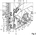
- FIG. 2 a schematic representation of a drive device 16 for mechanically driving the cutting knife 7 is shown.
- the ones in the Fig. 2 The drive device 16 shown is used on both sides of the cutting mechanism 1 to drive the respective cutting knife 7. Because of the identical design of the two drive devices 16 of the respective cutting knife 7, the following description of the FIG Fig. 2 drive device 16 shown correspondingly also for the oppositely arranged - not shown - drive device.
- the cutter bar 4 is driven by at least one gear 17 arranged at the end of the frame 2.
- the at least one gear 17 is connected to a drive shaft designed as a cardan shaft, which is arranged on the cutting unit 1.
- the respective gear 17 causes a rotational movement the drive shaft is converted into an oscillating translational movement of the mowing knives 5 arranged on the knife bar 5a.
- the respective drive device 16 of the cutting knife 7 comprises an output shaft 18 on which a compression spring 22 is arranged, a clutch 19 designed as a claw clutch, with two clutch halves 23, 24, and a drive shaft 20.
- One clutch half 23 is arranged at the end of the output shaft 18
- the other coupling half 24 is arranged at the end on the opposite drive shaft 20.
- the output shaft 18 and the coupling half 23 form components of the drive device 16 arranged on the cutterbar side, while the coupling half 24 and the output shaft 20 form the components of the drive device 16 arranged on the cutting blade side.
- the drive device 16 is arranged in a region of the cutting mechanism 1 close to the ground. Arrangement of the drive device 16 close to the ground means that the components of the drive device 16, which are arranged on the cutting table side of the cutting unit 1, are arranged at the same height as the at least one gear 17 or below the at least one gear 17 that drives the cutter bar 4. As a result, a collision-free displacement of the cutting knife 7 with respect to the reel 3 is achieved.
- a limiting means 25 is provided on each cutter bar 11 to limit the translational movement of the upper cutter 12 and lower cutter 13 in order to limit the vertical movements of the upper cutter 12 and lower cutter 13 both upwards and downwards in the event that the coupling 19 blocks .
- a transmission element 26 is arranged on each cutter bar 11, which is guided in the vertical direction in the delimitation means 25, which is designed as an elongated hole.
- two levers 27, 28 are spaced apart from each other and articulated eccentrically to the longitudinal axis of the drive shaft 20, one lever 27, 28 with the upper knife 12 and the other lever 28 with the lower knife 13 of the cutting knife 7 through the respective transmission element 26 is connected.
- a half-shell-shaped section 30 is arranged at the end of the floor panel 29 facing the cutting table 2a.
- the half-shell-shaped section 30 can be brought into positive engagement with a pivot axis 31 which is arranged in the region near the bottom on the frame 2 and runs essentially parallel to the cutter bar 4.
- the support frame 14 can be pivoted about the pivot axis 31.
- the representation in Fig. 2 shows the cutting knife 7 in its locked position on the cutting mechanism 1.
- a quick release fastener 32 is arranged on the support frame 14, which is detachably connected to the frame 2.
- the quick release fastener 32 has a hook-shaped section 33 which can be brought into engagement with a recess 34 in the frame 2.
- the quick release fastener 32 can be designed as a type of toggle lever arrangement.
- the hook-shaped section 33 which engages in the recess 34 to fix the support frame 14 enables a backlash-free and torque-resistant connection of the support frame 14 to the frame 2.
- FIG. 3 shows a partial view of the cutting mechanism 1 obliquely from the front.
- a coupling gear 35 is arranged on the cutter bar 4 adjacent to the side wall 6.
- the coupling gear 35 comprises a holding element 37 which is fastened to the cutter bar 4.
- a coupling rod 36 which runs essentially parallel to the cutter bar 4 and extends into the interior of the side wall 6, is articulated on the holding element 37.
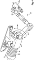
- Fig. 4 a view of the cutter-side components of the drive device 16 and the coupling gear 35 is shown.
- the coupling rod 36 is articulated with its free end to a coupling element 38.
- the coupling element 38 is connected non-rotatably to the output shaft 18 of the drive device 16.
- the output shaft 18 is rotatably mounted in a hollow cylindrical section 39 which is fastened to the frame 2 or the side wall 6.
- the oscillating The translational movement (arrow MB) of the cutter bar 4 is converted by the coupling gear 35 into a pendulum movement PB of the output shaft 18 of the drive device 16.
- Fig. 5 shows an illustration of the components of the drive device 16 on the cutting blade side.
- the two levers 27, 28 are articulated eccentrically to the longitudinal axis 40 of the drive shaft 20.
- the lever 27 is connected to the upper knife 12 and the other lever 28 is connected to the lower knife 13 of the separating knife 7.
- the levers 27, 28 have at their end facing away from the drive shaft 18 bearing points 41, in which the respective transmission element 26 of the upper cutter 12 or lower cutter 13 is articulated.
- the pendulum movement PB of the output shaft 18 is transmitted to the drive shaft 20 by the coupling 19.
- the levers 27 and 28, which are eccentrically articulated to the free end of the drive shaft 20, are excited to a vertically directed up and down movement 42 by the transmitted pendulum movement PB.
- the levers 27, 28 move in opposite directions, which leads to the corresponding movement (arrow 15) of the upper knife 12 and the lower knife 13.
- Fig. 6 a partial view of the cutting mechanism and a height adjustment element 43 for the height-adjustable attachment of an exchangeable stalk divider is shown.
- the stalk divider (not shown) is releasably attached to the side wall 6 of the frame 2 instead of the cutting knife 7.
- the height adjustment element 43 has at least one half-shell-shaped section 44 which can be brought into engagement with the pivot axis 31 arranged on the side wall 6 of the frame 2 in the area close to the floor.
- the height adjustment element 43 is preferably designed as an elongated, plate-shaped component and at the same time functions as an adapter for attaching the stalk divider.
- the height adjustment element 43 can have a fastening means 45 at an end opposite the half-shell-shaped section, by means of which the height adjustment element 43 can be connected to the side wall 6 on the frame 2 in a non-positive and / or positive manner.
- the arrangement of the height adjustment element 43 is thus carried out using at least some of the means arranged on the side wall 6 of the frame 2, ie the pivot axis 31, which is also used for the detachable connection of the cutting knife 7.
- an elongated hole 46 is provided in the height adjustment element 43, through which a - not shown - support arm of the stalk divider extends.
- the support arm extending through the elongated hole 46 is releasably articulated with a free end on a pivot axis in the interior of the side wall 6 of the frame 2.
- the support arm of the straw divider is held by a receptacle 47 which is displaceable in the longitudinal direction of the height adjustment element 43.
- the receptacle 47 is arranged in the lower region of the elongated hole 46 facing the cutter bar 4.
- the receptacle 47 is designed to be open at the top.
- the support arm can thus be placed in the receptacle 47 and is held in the receptacle 47 due to the force of gravity.
- a plate-shaped section 48 which, together with the receptacle 47, can be displaced relative to the height adjustment element 43 in the longitudinal direction, that is to say in the vertical direction.
- the plate-shaped section 48 can be fixed in different height positions by means of a locking device 49. By moving and then locking the plate-shaped section 48, the height of the stalk divider can be adjusted.
Landscapes
- Life Sciences & Earth Sciences (AREA)
- Environmental Sciences (AREA)
- Harvester Elements (AREA)
Abstract
Description
- Die vorliegende Erfindung betrifft ein Schneidwerk gemäß dem Oberbegriff des Anspruches 1.
- Schneidwerke kommen zum Ernten von unterschiedlichen Fruchtarten wie Getreide, Raps und dergleichen zum Einsatz. Ein Schneidwerk umfasst einen Rahmen und eine daran angeordnete Schneidwerksmulde, einen der Schneidwerksmulde vorgeordneten Schneidtisch mit einem daran angeordneten, durch zumindest ein Getriebe oszillierend angetriebenen Messerbalken, eine rotativ angetriebenen Haspel, die mittels Tragarmen an der Schneidwerksmulde geführt und gegenüber dieser in oder entgegen der Mährichtung verstellbar ist, sowie zumindest einem endseitig an dem Rahmen lösbar angeordneten Trennmesser, welches sich im Wesentlichen vertikal zu dem Messerbalken erstreckt. Einzelne Komponenten der Schneidwerke sind an die jeweilige zu erntende Fruchtart durch eine gezielte Einstellung anpassbar, wie beispielsweise die Ausfahrlänge einer Haspel. Weiterhin sind zusätzliche Komponenten an dem Schneidwerk montierbar, im Fall unter anderem von Raps die Trennmesser oder sogenannten Rapsmesser. Die seitlich angeordneten Trennmesser dienen dazu, stark ineinander verschlungenes Erntegut beiderseits des Schneidwerks in einer vertikalen Ebene zu zerteilen, um Ernteverluste zu reduzieren. Bei Sonderkulturen wie beispielsweise Raps, die eine starke Verwachsung der Stängel und Fruchtteile ineinander zeigen, gewährleisten die Trennmesser eine gute Trennung des Halmgutes zwischen dem noch stehenden und dem vom Schneidtisch aufzunehmenden Erntegutes. Ernteverluste, die mit der Verwendung eines üblichen passiven Halmteilers einhergingen, werden so vermieden. Das Schneidwerk wird an einer Aufnahmevorrichtung eines Mähdreschers aufgenommen, welcher die für den Betrieb des Schneidwerkes notwendigen Antriebskräfte bereitstellt. Hierzu wird das Schneidwerk an ein Hydrauliksystem des Mähdreschers sowie an einen mechanischen Antriebsstrang des Mähdreschers anschlossen.
- Ein Schneidwerk der eingangs genannten Art ist aus der
EP 2 647 276 A1 bekannt. Darin wird ein Schneidwerk mit einem Rahmen und einer daran angeordneten Schneidwerksmulde, einem der Schneidwerksmulde vorgeordneten Schneidtisch mit einem daran angeordneten oszillierend angetriebenen Messerbalken, einer rotativ angetriebenen Haspel, die mittels Tragarmen an der Schneidwerksmulde geführt und gegenüber dieser in oder entgegen der Mährichtung verstellbar ist, sowie zumindest einem endseitig an dem Rahmen lösbar angeordneten Trennmesser, welches sich im Wesentlichen vertikal zu dem Messerbalken erstreckt beschrieben. Zum Antreiben von an dem Mähbalken angeordneten Mähmessern ist jeweils ein Getriebe endseitig an in Mährichtung weisenden Seitenwänden des Rahmens angeordnet, welche jeweils eine Rotationsbewegung einer an dem Schneidwerk angeordneten Antriebswelle in eine oszillierend translatorische Bewegung der Mähmesser umsetzen. Die Getriebe sind als Kegelradgetriebe ausgeführt, wobei ein Kegelrad mit einer von einem Mähdrescher angetriebenen, horizontal verlaufenden Abtriebswelle verbunden ist. Das Kegelrad treibt ein unter einem Winkel von 90° angeordnetes Kegelrad an, welches die Rotationsbewegung an ein unterhalb des angetriebenen Kegelrades nachgeordnetes Getriebe zum Antreiben an den Messerbalken überträgt. An dem an der Abtriebswelle angeordneten Kegelrad ist eine ebenfalls horizontal verlaufende Ausgangswelle angeschlossen, welcher dem Antrieb eines der endseitig an dem Rahmen angeordneten Trennmesser dient. - Ausgehend vom vorstehend genannten Stand der Technik liegt der Erfindung die Aufgabe zugrunde, ein Schneidwerk in der Weise weiterzubilden, dass es sich durch eine erhöhte Funktionssicherheit auszeichnet.
- Diese Aufgabe wird erfindungsgemäß durch ein Schneidwerk gemäß den Merkmalen des Anspruches 1 gelöst.
- Gemäß dem Anspruch 1 wird ein Schneidwerk vorgeschlagen, mit einem Rahmen und einer daran angeordneten Schneidwerksmulde, einem der Schneidwerksmulde vorgeordneten Schneidtisch mit einem daran angeordneten, durch zumindest ein Getriebe oszillierend angetriebenen Messerbalken, einer rotativ angetriebenen Haspel, die mittels Tragarmen an der Schneidwerksmulde geführt und gegenüber dieser in oder entgegen einer Mährichtung verstellbar ist, sowie zumindest einem endseitig an dem Rahmen lösbar angeordneten Trennmesser, welches sich im Wesentlichen vertikal zu dem Messerbalken erstreckt, wobei der Schneidtisch gegenüber der Schneidwerksmulde in oder entgegen der Mährichtung verschiebbar ist, wobei eine Antriebsvorrichtung des zumindest einen Trennmessers in einem bodennahen Bereich befindet, wobei die Antriebsvorrichtung durch ein Koppelgetriebe mit dem Messerbalken verbunden ist, welches die oszillierende Bewegung des Messerbalkens auf das zumindest eine Trennmesser übertragt. Durch die bodennahe Anordnung der Antriebsvorrichtung des zumindest einen Trennmessers kann eine Kollision zwischen diesem und der Haspel vermieden werden, insbesondere dann, wenn der Schneidtisch und die Haspel, beispielsweise zu Transportzwecken, entgegen der Mährichtung vollständig eingefahren werden muss. Der Schneidtisch ist entlang eines Verfahrweges verstellbar, wobei dieser ausgehend von einer Ausgangsposition in Mährichtung ausgefahren wird, was einem positiven Verfahrweg entspricht. Darüber hinaus ist der Schneidtisch über die Ausgangsposition entgegen der Mährichtung verfahrbar, was einem negativen Verfahrweg entspricht. Der positive Verfahrweg ist größer als der negative Verfahrweg. Die Haspel wird entsprechend des Verfahrweges des Schneidtisches verfahren, um Kollisionen zu vermeiden. Das Verfahren der Haspel entgegen der Mährichtung ist bei montiertem Trennmesser aufgrund der kollisionsfreien Anordnung der Antriebsvorrichtung des Trennmessers möglich. Dies ermöglicht darüber hinaus den Einsatz der Trennmesser beim Ernten von Getreide oder Bohnen, wenn der Pflanzenbestand stark verschlungen ist, wobei der Schneidtisch und die Haspel entlang des negativen Verfahrweges verstellt werden. Bodennahe Anordnung der Antriebsvorrichtung bedeutet, dass die Komponenten der Antriebsvorrichtung, die schneidtischseitig angeordnet sind, auf gleicher Höhe mit dem zumindest einen Getriebe oder unterhalb des zumindest einen Getriebes, das den Messerbalken antreibt, angeordnet sind.
- Hierbei kann das Koppelgetriebe eine an dem Messerbalken angelenkte, sich im Wesentlichen parallel zu dem Messerbalken erstreckende Koppelstange umfassen, welche mit ihrem freien Ende an einem drehfest mit einer Abtriebswelle verbunden Koppelelement angreift. Die Koppelstange kann die oszillierende Bewegung des Messerbalkens gleichförmig auf die Abtriebswelle übertragen, so dass diese innerhalb eines Winkelbereichs um eine Ausgangslage eine Pendelbewegung ausführt.
- Bevorzugt kann die Antriebsvorrichtung eine Antriebswelle umfassen, die durch eine Kupplung mit der Abtriebswelle lösbar verbunden ist. Die Kupplung kann bevorzugt als eine Klauenkupplung ausgeführt sein. Durch die Kupplung können die an dem Trennmesser angeordnete Antriebswelle und die an dem Schneidwerk angeordnete Abtriebswelle getrennt werden, um die Trennmesser vom Schneidwerk lösen zu können. Die als Klauenkupplung ausgeführte Kupplung fungiert dabei als Überlastsicherung für das jeweilige Trennmesser. Hierzu kann die Klauenkupplung mit einer Federkraft beaufschlagt sein. Die Beaufschlagung der Klauenkupplung mit der Federkraft erfolgt auf Seiten des Vorsatzgerätes, so dass ein spielfreies Ankoppeln des Trennmessers möglich ist.
- Weiterhin können am freien Ende der Antriebswelle zwei Hebel exzentrisch zur Längsachse der Antriebswelle angelenkt sein, wobei ein Hebel mit einem Obermesser und der andere Hebel mit einem Untermesser des Trennmessers verbunden ist, wobei das Obermesser und das Untermesser parallel zueinander angeordnet sind. Die beiden exzentrisch zur Längsachse der Antriebswelle angelenkten Hebel übertragen die Pendelbewegung der Antriebswelle auf das Obermesser bzw. das Untermesser, so dass diese eine oszillierende translatorische Bewegung ausführen können.
- Insbesondere kann das Trennmesser einen Tragrahmen aufweisen, an welchem das Obermesser und das Untermesser angeordnet sind, welche in an dem Schneidwerk montierter Position des Trennmessers in Mährichtung weisen, wobei auf der dem Obermesser und dem Untermesser abgewandten Seite des Tragrahmens Mittel zur lösbaren Verbindung mit dem Rahmen respektive an den äußeren Enden des Rahmens angeordneten Seitenwänden vorgesehen sind.
- Zur Begrenzung der translatorischen Bewegung von Obermesser und Untermesser ist vorgesehen, dass für den Fall einer blockierenden Kupplung der Verstellweg der beiden an dem freien Ende der Antriebswelle angeordneten Hebel in vertikaler Richtung durch jeweils ein Begrenzungsmittel limitiert ist. Das jeweilige Begrenzungsmittel kann dazu als ein Anschlag ausgeführt sein, welcher die vertikale Bewegung von einem jeweils endseitig an den Hebeln angeordneten Übertragungselement in beiden Richtungen, nach oben und nach unten, begrenzt. Die Übertragungselemente übertragen die Pendelbewegung der Hebel um die Antriebswelle als Auf- und Abbewegung auf das Obermesser bzw. Untermesser.
- Bevorzugt können die Mittel einen halbschalenförmigen Abschnitt im bodennahen Bereich des Trennmessers und einen hierzu beabstandet am Tragrahmen angeordneten Schnellspannverschluss umfassen, wobei der halbschalenförmige Abschnitt mit einer im bodennahen Bereich am Rahmen respektive Seitenwand angeordneten, im Wesentlichen parallel zum Messerbalken verlaufenden Schwenkachse in Eingriff bringbar ist. Mittels des halbschalenförmigen Abschnitts lässt sich der Tragrahmen formschlüssig mit der Schwenkachse in Eingriff bringen und um diese in Richtung des Schneidwerks schwenken.
- Weiterhin kann der Schnellspannverschluss einen hakenförmigen Abschnitt aufweisen, welcher mit einer Ausnehmung im Rahmen des Schneidwerks in Eingriff bringbar ist. Um den hakenförmigen Abschnitt in seiner in Eingriff mit der Ausnehmung gebrachten Position zu fixieren, kann der Schnellspannverschluss mit einer Kniehebelanordnung ausgeführt sein. Hierdurch wird eine spielfreie und drehmomentsteife Verbindung zwischen dem Tragrahmen des Trennmessers und dem Rahmen des Schneidwerks geschaffen.
- Gemäß einer bevorzugten Weiterbildung kann an dem Rahmen ein um eine Drehachse schwenkbarer Halmteiler anstelle des Trennmessers lösbar montiert sein. Die Befestigung des Halmteilers erfolgt dabei an einer horizontal verlaufenden Drehachse an dem Rahmen, so dass der Halmteiler um diese in vertikaler Richtung ausgelenkt werden kann. Dies ermöglicht unterschiedliche Höheneinstellungen des Halmteilers.
- Dabei kann an dem Rahmen zur Begrenzung der Auslenkung des Halmteilers in vertikaler Richtung ein Höheneinstellelement lösbar befestigt ist, wobei das Höheneinstellelement durch zumindest einen halbschalenförmigen Abschnitt mit der im bodennahen Bereich am Rahmen angeordneten Schwenkachse in Eingriff bringbar ist. Das Höheneinstellelement ist bevorzugt als ein längliches, plattenförmiges Bauteil ausgeführt und fungiert zugleich als Adapter für die Anbringung des Halmteilers. Das Höheneinstellelement kann an einem dem halbschalenförmigen Abschnitt gegenüberliegenden Ende ein Befestigungsmittel aufweisen, durch welches das Höheneinstellelement kraft- und/oder formschlüssig mit dem Rahmen verbindbar ist. Die Anordnung des Höheneinstellelementes erfolgt somit unter Verwendung zumindest eines Teils der am Rahmen angeordneten Mittel, die auch zur lösbaren Verbindung des Trennmessers verwendet werden.
- Bevorzugt kann zur Begrenzung der vertikalen Auslenkung und zur Führung des Halmteilers in dem Höheneinstellelement ein Langloch vorgesehen sein, durch das sich ein Tragarm des Halmteilers erstreckt. Der sich durch das Langloch erstreckende Tragarm ist mit einem freien Ende an der Drehachse des Rahmens lösbar angelenkt. Der Tragarm des Halmteilers ist von einer Aufnahme gehalten, welche in Längsrichtung des Höheneinstellelementes, d.h. in vertikaler Richtung, verschieblich ist. Die Aufnahme ist im unteren, dem Messerbalken zugewandten Bereich des Langlochs angeordnet. Die Aufnahme ist nach oben hin offen ausgeführt.
- Der Tragarm kann somit der in der Aufnahme abgelegt werden und wird aufgrund der Schwerkraft in der Aufnahme gehalten. Unterhalb der Aufnahme ist ein plattenförmiger Abschnitt angeordnet, der relativ zu dem Höheneinstellelement verschiebbar ist. Mittels einer Arretiervorrichtung ist der plattenförmige Abschnitt in verschiedenen Höhenpositionen festlegbar. Durch das Verschieben und anschließende Arretieren des plattenförmigen Abschnitts lässt sich die Höhe des Halmteilers einstellen.
- Die vorliegende Erfindung wird nachstehend anhand eines in den Zeichnungen dargestellten Ausführungsbeispieles näher erläutert.
- Es zeigen:
- Fig. 1
- eine schematische Darstellung eines Schneidwerks mit daran angeordneten Trennmessern;
- Fig. 2
- eine Teilansicht einer Antriebsvorrichtung des Trennmessers;
- Fig. 3
- eine Teilansicht des Schneidwerks von schräg vorne;
- Fig. 4
- eine Ansicht schneidwerkseitiger Komponenten der Antriebsvorrichtung sowie ein Koppelgetriebe;
- Fig. 5
- eine Ansicht trennmesserseitiger Komponenten der Antriebsvorrichtung; und
- Fig. 6
- eine Teilansicht des Schneidwerks sowie eines Höheneinstellelementes zur höhenverstellbaren Anbringung eines Halmteilers.
-
Fig. 1 zeigt eine schematische Darstellung eines Schneidwerks 1 mit endseitig angeordneten Trennmessern 7. Das Schneidwerk 1 wird von einem - nicht dargestellten - Mähdrescher aufgenommen und durch diesen angetrieben. Hierzu wird das Schneidwerk 1 mit einem mechanischen Antriebsstrang des Mähdreschers gekoppelt. Zudem kann eine Anbindung des Schneidwerks 1 an ein Hydrauliksystem des Mähdreschers vorgesehen sein, um Komponenten des Schneidwerks 1, wie beispielsweise eine Haspel 3, hydraulisch anzutreiben. Die Haspel 3 ist mittels Tragarmen 3a an der Schneidwerksmulde 2b geführt und gegenüber dieser in oder entgegen einer Mährichtung verstellbar. Weiterhin kann das Schneidwerk 1 durch zumindest eine Zuleitung 10 mit einer Steuerungsvorrichtung 8 des Mähdreschers verbunden. Weiterhin ist dem Schneidwerk 1 eine Bedieneinrichtung 9 zugeordnet, welche vorzugsweise in einer Kabine des Mähdreschers angeordnet ist. Dabei kann die Bedieneinrichtung 9 in die Steuerungsvorrichtung 8 des Mähdreschers integriert sein. Die Bedieneinrichtung 9 kann auch unmittelbar an dem Schneidwerk 1 angeordnet sein. - Das Schneidwerk 1 umfasst einen Rahmen 2 mit einem Schneidtisch 2a, an den sich eine Schneidmulde 2b anschließt. In der schematischen Darstellung ist der Schneidtisch 2a von der Schneidwerksmulde 2b separiert und gegenüber dieser längsverschiebbar ausgeführt. Die Längsverschiebbarkeit des Schneidtischs 2a ermöglicht eine Anpassung an unterschiedliche Erntegutarten. Hierzu ist der Schneidtisch 2a entlang eines Verfahrweges verstellbar, wobei dieser ausgehend von einer Ausgangsposition AP in Mährichtung ausgefahren wird, was einem positiven Verfahrweg PVF entspricht. Darüber hinaus ist der Schneidtisch 2a über die Ausgangsposition AP hinweg entgegen der Mährichtung verfahrbar, was einem negativen Verfahrweg NVF entspricht. Der positive Verfahrweg PVF ist größer als der negative Verfahrweg NVF des Schneidtisches 2a. An der Vorderkante des Schneidtischs 2a ist ein horizontal verlaufender, angetriebener Messerbalken 4 angeordnet ist, der an zumindest einer hin und her beweglichen Messerschiene 5a angeordnete Mähmesser 5 aufweist. Die oszillierende Bewegung des Messerbalkens 4 wird durch den Pfeil MB veranschaulicht. An dem Rahmen 2 sind an beiden außenseitigen Enden mehrteilige Seitenwände 6 angeordnet, die in Mährichtung respektive Fahrrichtung des Mähdreschers weisen. Die mehrteiligen Seitenwände 6 sind partiell zusammen mit dem Schneidtisch 2a längsverschiebbar. Weiterhin sind jeweils endseitig an dem Rahmen 2 lösbar befestigbare Trennmesser 7 angeordnet, welche sich im Wesentlichen vertikal zu dem Messerbalken 4 erstrecken. Die Trennmesser 7 sind gemeinsam mit dem Schneidtisch 2a und den verschiebbaren Teilen der Seitenwänden 6 entlang des gesamten Verfahrweges, d.h. sowohl entlang des positiven Verfahrweges PVF als auch des negativen Verfahrweges NVF, kollisionsfrei verschiebbar. Die Trennmesser 7 weisen jeweils oszillierend angetriebene, parallel zueinander angeordnete Mähbalken 11 auf. Die Mähbalken 11 sind in vertikaler Richtung durch Führungselemente 21 geführt. An jeweils einem Mähbalken 11 sind Obermesser 12 bzw. Untermesser 13 angeordnet. Die Obermesser 12 und Untermesser 13 bewegen sich oszillierend in vertikaler Richtung (Pfeil 15). Dabei bewegen sich das Obermesser 12 und das Untermesser 13 gegenläufig. Zur Anbringung der Trennmesser 7 an dem Schneidtisch 2a weist jedes Trennmesser 7 einen Tragrahmen 14 auf. Die Bedieneinrichtung 9 kann der Bedienung des Schneidwerkes 1 dienen, zumindest um zumindest eines der Trennmesser 7 im laufenden Betrieb des Messerbalkens 4 zu- und abschalten zu können.
- In
Fig. 2 ist eine schematische Darstellung einer Antriebsvorrichtung 16 zum mechanischen Antreiben des Trennmessers 7 gezeigt. Die in derFig. 2 dargestellte Antriebsvorrichtung 16 kommt auf beiden Seiten des Schneidwerks 1 zum Antreiben des jeweiligen Trennmessers 7 zum Einsatz. Wegen der identischen Ausgestaltung der beiden Antriebsvorrichtungen 16 des jeweiligen Trennmessers 7 gilt die nachfolgende Beschreibung der inFig. 2 gezeigten Antriebsvorrichtung 16 entsprechend auch für die gegenüberliegend angeordnete - nicht dargestellte - Antriebsvorrichtung. - Der Messerbalken 4 wird durch zumindest ein endseitig an dem Rahmen 2 angeordnetes Getriebe 17 angetrieben. Das zumindest eine Getriebe 17 ist mit einer als Gelenkwelle ausgeführten Antriebswelle verbunden, die an dem Schneidwerk 1 angeordnet ist. Durch das jeweilige Getriebe 17 wird eine Rotationsbewegung der Antriebswelle in eine oszillierende translatorische Bewegung der an der Messerschiene 5a angeordneten Mähmesser 5 umgesetzt. Die jeweilige Antriebsvorrichtung 16 der Trennmesser 7 umfasst eine Abtriebswelle 18, auf welcher eine Druckfeder 22 angeordnet ist, eine als Klauenkupplung ausgeführte Kupplung 19, mit zwei Kupplungshälften 23, 24, sowie eine Antriebswelle 20. Die eine Kupplungshälfte 23 ist endseitig an der Abtriebswelle 18 angeordnet, während die andere Kupplungshälfte 24 endseitig an der gegenüberliegenden Antriebswelle 20 angeordnet ist. Die Abtriebswelle 18 und die Kupplungshälfte 23 bilden schneidwerkseitig angeordnete Komponenten der Antriebsvorrichtung 16, während die Kupplungshälfte 24 und die Abtriebswelle 20 die trennmesserseitig angeordneten Komponenten der Antriebsvorrichtung 16 bilden. Die Antriebsvorrichtung 16 ist in einem bodennahen Bereich des Schneidwerks 1 angeordnet. Bodennahe Anordnung der Antriebsvorrichtung 16 bedeutet, dass die Komponenten der Antriebsvorrichtung 16, die schneidtischseitig am Schneidwerk 1 angeordnet sind, auf gleicher Höhe mit dem zumindest einen Getriebe 17 oder unterhalb des zumindest einen Getriebes 17, das den Messerbalken 4 antreibt, angeordnet sind. Hierdurch wird ein gegenüber der Haspel 3 kollisionsfreies Verschieben der Trennmesser 7 erreicht.
- An dem jeweiligen Mähbalken 11 ist zur Begrenzung der translatorischen Bewegung von Obermesser 12 und Untermesser 13 jeweils ein Begrenzungsmittel 25 vorgesehen, um für den Fall, dass die Kupplung 19 blockiert, die von Obermesser 12 und Untermesser 13 sowohl aufwärts als auch abwärts gerichteten Vertikalbewegungen zu begrenzen. Hierzu ist an jedem Mähbalken 11 ein Übertragungselement 26 angeordnet, welches in vertikaler Richtung in dem als Langloch ausgeführten Begrenzungsmittel 25 geführt ist. An dem freien Ende der Antriebswelle 20 sind zwei Hebel 27, 28 beabstandet zueinander und exzentrisch zur Längsachse der Antriebswelle 20 an dieser angelenkt, wobei ein Hebel 27, 28 mit dem Obermesser 12 und der andere Hebel 28 mit dem Untermesser 13 des Trennmessers 7 durch das jeweilige Übertragungselement 26 verbunden ist.
- An dem Tragrahmen 14 ist ein sich im Wesentlichen in horizontaler Richtung erstreckendes Bodenblech 29 angeordnet, oberhalb dessen sich die Komponenten der Antriebsvorrichtung 16 befinden. Am dem Schneidtisch 2a zugewandten Ende des Bodenblechs 29 ist ein halbschalenförmiger Abschnitt 30 angeordnet. Der halbschalenförmige Abschnitt 30 lässt sich mit einer mit einer im bodennahen Bereich am Rahmen 2 angeordneten, im Wesentlichen parallel zum Messerbalken 4 verlaufenden Schwenkachse 31 in formschlüssig Eingriff bringen. Der Tragrahmen 14 ist um die Schwenkachse 31 schwenkbar. Die Darstellung in
Fig. 2 zeigt das Trennmesser 7 in seiner an dem Schneidwerk 1 arretierten Position. Hierzu ist ein Schnellspannverschluss 32 an dem Tragrahmen 14 angeordnet, welcher mit dem Rahmen 2 lösbar verbunden ist. Der Schnellspannverschluss 32 weist einen hakenförmigen Abschnitt 33 auf, welcher mit einer Ausnehmung 34 im Rahmen 2 in Eingriff bringbar ist. Der Schnellspannverschluss 32 kann als eine Art Kniehebelanordnung ausgeführt sein. Der zur Fixierung des Tragrahmens 14 in die Ausnehmung 34 eingreifende hakenförmigen Abschnitt 33 ermöglicht eine spielfreie und drehmomentsteife Verbindung des Tragrahmens 14 am Rahmen 2. - Die Darstellung in
Fig. 3 zeigt eine Teilansicht des Schneidwerks 1 von schräg vorne. Benachbart zur Seitenwand 6 ist ein Koppelgetriebe 35 an dem Messerbalken 4 angeordnet. Das Koppelgetriebe 35 umfasst ein Halteelement 37, welches an dem Messerbalken 4 befestigt ist. An dem Halteelement 37 ist eine Koppelstange 36 angelenkt, die im Wesentlichen parallel zum Messerbalken 4 verläuft und sich in das Innere der Seitenwand 6 erstreckt. - In
Fig. 4 ist eine Ansicht der schneidwerkseitigen Komponenten der Antriebsvorrichtung 16 sowie das Koppelgetriebe 35 dargestellt. Die Koppelstange 36 ist mit ihrem freien Ende an einem Koppelelement 38 angelenkt. Das Koppelelement 38 ist drehfest mit der Abtriebswelle 18 der Antriebsvorrichtung 16 verbunden. Die Abtriebswelle 18 ist hierfür in einem hohlzylindrischen Abschnitt 39 drehbar gelagert, der an dem Rahmen 2 bzw. der Seitenwand 6 befestigt ist. Die oszillierende translatorische Bewegung (Pfeil MB) des Messerbalkens 4 wird von dem Koppelgetriebe 35 in eine Pendelbewegung PB der Abtriebswelle 18 der Antriebsvorrichtung 16 überführt. -
Fig. 5 zeigt eine Darstellung der trennmesserseitigen Komponenten der Antriebsvorrichtung 16. Am freien Ende der Antriebswelle 20 sind die zwei Hebel 27, 28 exzentrisch zur Längsachse 40 der Antriebswelle 20 angelenkt. Der Hebel 27 ist mit dem Obermesser 12 und der andere Hebel 28 mit dem Untermesser 13 des Trennmessers 7 verbunden. Die Hebel 27, 28 weisen an ihrem der Antriebswelle 18 abgewandten Ende Lagerstellen 41 auf, in welchen das jeweilige Übertragungselement 26 von Obermesser 12 bzw. Untermesser 13 angelenkt ist. Die Pendelbewegung PB der Abtriebswelle 18 wird durch die Kupplung 19 auf die Antriebswelle 20 übertragen. Die exzentrisch an dem freien Ende der Antriebswelle 20 angelenkten Hebel 27 und 28 werden durch die übertrage Pendelbewegung PB zu einer vertikal gerichteten Auf- und Abbewegung 42 angeregt. Dabei bewegen sich die Hebel 27, 28 gegensinnig, was zu der korrespondierenden Bewegung (Pfeil 15) von Obermesser 12 und Untermesser 13 führt. - In
Fig. 6 ist eine Teilansicht des Schneidwerks sowie ein Höheneinstellelement 43 zur höhenverstellbaren Anbringung eines auswechselbaren Halmteilers dargestellt. Dabei wird der - nicht dargestellte - Halmteiler anstelle des Trennmesser 7 an der Seitenwand 6 des Rahmens 2 lösbar befestigt. Hierzu weist das Höheneinstellelement 43 zumindest einen halbschalenförmigen Abschnitt 44 auf, welcher mit der im bodennahen Bereich an der Seitenwand 6 des Rahmens 2 angeordneten Schwenkachse 31 in Eingriff bringbar ist. Das Höheneinstellelement 43 ist bevorzugt als ein längliches, plattenförmiges Bauteil ausgeführt und fungiert zugleich als Adapter für die Anbringung des Halmteilers. Das Höheneinstellelement 43 kann an einem dem halbschalenförmigen Abschnitt gegenüberliegenden Ende ein Befestigungsmittel 45 aufweisen, durch welches das Höheneinstellelement 43 kraft-und/oder formschlüssig mit der Seitenwand 6 an dem Rahmen 2 verbindbar ist. Die Anordnung des Höheneinstellelementes 43 erfolgt somit unter Verwendung zumindest eines Teils der an der Seitenwand 6 des Rahmens 2 angeordneten Mittel, d.h. der Schwenkachse 31, die auch zur lösbaren Verbindung des Trennmessers 7 verwendet wird. - Zur Begrenzung der vertikalen Auslenkung und zur Führung des Halmteilers ist ein Langloch 46 in dem Höheneinstellelement 43 vorgesehen, durch welches sich ein - nicht dargestellter - Tragarm des Halmteilers erstreckt. Der sich durch das Langloch 46 erstreckende Tragarm ist mit einem freien Ende an einer Schwenkachse im Inneren der Seitenwand 6 des Rahmens 2 lösbar angelenkt. Der Tragarm des Halmteilers ist von einer Aufnahme 47 gehalten, welche in Längsrichtung des Höheneinstellelementes 43 verschieblich ist. Die Aufnahme 47 ist im unteren, dem Messerbalken 4 zugewandten Bereich des Langlochs 46 angeordnet. Die Aufnahme 47 ist nach oben hin offen ausgeführt. Der Tragarm kann somit der in der Aufnahme 47 abgelegt werden und wird aufgrund der Schwerkraft in der Aufnahme 47 gehalten. Unterhalb der Aufnahme 47 ist ein plattenförmiger Abschnitt 48 angeordnet, der gemeinsam mit der Aufnahme 47 relativ zu dem Höheneinstellelement 43 in Längsrichtung, d.h. vertikaler Richtung, verschiebbar ist. Mittels einer Arretiervorrichtung 49 ist der plattenförmige Abschnitt 48 in verschiedenen Höhenpositionen festlegbar. Durch das Verschieben und anschließende Arretieren des plattenförmigen Abschnitts 48 lässt sich die Höhe des Halmteilers einstellen.
Bezugszeichenliste 1 Schneidwerk 27 Hebel 2 Rahmen 28 Hebel 2a Schneidtisch 29 Bodenblech 2b Schneidmulde 30 Abschnitt 3 Haspel 31 Schwenkachse 3a Tragarm 32 Schnellspannverschluss 4 Messerbalken 33 Abschnitt 5 Mähmesser 34 Ausnehmung 5a Messerschiene 35 Koppelgetriebe 6 Seitenwand 36 Koppelstange 7 Trennmesser 37 Halteelement 8 Steuerungsvorrichtung 38 Koppelelement 9 Bedieneinrichtung 39 Abschnitt 10 Zuleitung 40 Längsachse 11 Mähbalken 41 Lagerstelle 12 Obermesser 42 Auf- und Abbewegung 13 Untermesser 43 Höheneinstellelement 14 Tragrahmen 44 Abschnitt 15 Pfeil 45 Befestigungsmittel 16 Antriebsvorrichtung 46 Langloch 17 Getriebe 47 Aufnahme 18 Abtriebswelle 48 Abschnitt 19 Kupplung 49 Arretiervorrichtung 20 Antriebswelle 21 Führungselement MB Pfeil 22 Druckfeder AP Ausgangspunkt 23 Kupplungshälfte PVF Positiver Verfahrweg 24 Kupplungshälfte NVF Negativer Verfahrweg 25 Begrenzungsmittel PB Pendelbewegung 26 Übertragungselement
Claims (10)
- Schneidwerk (1), mit einem Rahmen (2) und einer daran angeordneten Schneidwerksmulde (2b), einem der Schneidwerksmulde (2b) vorgeordneten Schneidtisch (2a) mit einem daran angeordneten, durch zumindest ein Getriebe (17) oszillierend angetriebenen Messerbalken (4), einer rotativ angetriebenen Haspel (3), die mittels Tragarmen (3a) an der Schneidwerksmulde (2b) geführt und gegenüber dieser in oder entgegen einer Mährichtung verstellbar ist, sowie zumindest einem endseitig an dem Rahmen (2) lösbar angeordneten Trennmesser (7), welches sich im Wesentlichen vertikal zu dem Messerbalken (4) erstreckt, dadurch gekennzeichnet, dass der Schneidtisch (2a) gegenüber der Schneidwerksmulde (2b) in oder entgegen der Mährichtung verschiebbar ist, wobei eine Antriebsvorrichtung (16) des zumindest einen Trennmessers (7) in einem bodennahen Bereich befindet, wobei die Antriebsvorrichtung (16) durch ein Koppelgetriebe (35) mit dem Messerbalken (4) verbunden ist, welches die oszillierende Bewegung des Messerbalkens (4) auf das zumindest eine Trennmesser (7) übertragt.
- Schneidwerk (1) nach Anspruch 1, dadurch gekennzeichnet, dass das Koppelgetriebe (35) eine an dem Messerbalken (4) angelenkte, sich im Wesentlichen parallel zu dem Messerbalken (4) erstreckende Koppelstange (36) umfasst, welche mit ihrem freien Ende an einem drehfest mit einer Abtriebswelle (18) verbunden Koppelelement (38) angreift.
- Schneidwerk (1) nach Anspruch 2, dadurch gekennzeichnet, dass die Antriebsvorrichtung (16) eine Antriebswelle (20) umfasst, die durch eine Kupplung (19) mit der Abtriebswelle (18) lösbar verbunden ist.
- Schneidwerk (1) nach Anspruch 3, dadurch gekennzeichnet, dass am freien Ende der Antriebswelle (20) zwei Hebel (27, 28) exzentrisch zur Längsachse (40) der Antriebswelle (20) angelenkt sind, wobei ein Hebel (27) mit einem Obermesser (12) und der andere Hebel (28) mit einem Untermesser (13) des Trennmessers (7) verbunden ist, wobei das Obermesser (12) und das Untermesser (13) parallel zueinander angeordnet sind.
- Schneidwerk (1) nach Anspruch 4, dadurch gekennzeichnet, dass das Trennmesser (7) einen Tragrahmen (14) aufweist, an welchem das Obermesser (12) und das Untermesser (13) angeordnet sind, welche in an dem Schneidwerk (1) montierter Position des Trennmessers (7) in Mährichtung weisen, wobei auf der dem Obermesser (12) und Untermesser (13) abgewandten Seite des Tragrahmens (14) Mittel zur lösbaren Verbindung mit dem Rahmen (2) vorgesehen sind.
- Schneidwerk (1) nach Anspruch 5, dadurch gekennzeichnet, dass die Mittel einen halbschalenförmigen Abschnitt (30) im bodennahen Bereich des Trennmessers (7) und einen hierzu beabstandet am Tragrahmen (14) angeordneten Schnellspannverschluss (32) umfassen, wobei der halbschalenförmige Abschnitt (30) mit einer im bodennahen Bereich am Rahmen (2) angeordneten Schwenkachse (31) in Eingriff bringbar ist.
- Schneidwerk (1) nach Anspruch 6, dadurch gekennzeichnet, dass der Schnellspannverschluss (32) einen hakenförmigen Abschnitt (33) aufweist, welcher mit einer Ausnehmung (34) im Rahmen (2) in Eingriff bringbar ist.
- Schneidwerk (1) nach einem der Ansprüche 1 bis 7, dadurch gekennzeichnet, dass an dem Rahmen (2) ein um eine Drehachse schwenkbarer Halmteiler anstelle des Trennmessers (7) lösbar montiert ist.
- Schneidwerk (1) nach Anspruch 8, dadurch gekennzeichnet, dass an dem Rahmen (2) zur Begrenzung der Auslenkung des Halmteilers in vertikaler Richtung ein Höheneinstellelement (43) lösbar befestigt ist, wobei das Höheneinstellelement (43) durch zumindest einen halbschalenförmigen Abschnitt (44) mit der im bodennahen Bereich am Rahmen (2) angeordneten Schwenkachse (31) in Eingriff bringbar ist.
- Schneidwerk (1) nach Anspruch 8 oder 9, dadurch gekennzeichnet, dass zur Begrenzung der Auslenkung und zur Führung des Halmteilers gegenüber dem Höheneinstellelement (43) ein Langloch (46) vorgesehen ist, durch das sich ein Tragarm des Halmteilers erstreckt.
Applications Claiming Priority (1)
| Application Number | Priority Date | Filing Date | Title |
|---|---|---|---|
| DE102019111212.5A DE102019111212A1 (de) | 2019-04-30 | 2019-04-30 | Schneidwerk |
Publications (2)
| Publication Number | Publication Date |
|---|---|
| EP3732948A1 true EP3732948A1 (de) | 2020-11-04 |
| EP3732948B1 EP3732948B1 (de) | 2023-03-08 |
Family
ID=69159663
Family Applications (1)
| Application Number | Title | Priority Date | Filing Date |
|---|---|---|---|
| EP20151431.2A Active EP3732948B1 (de) | 2019-04-30 | 2020-01-13 | Schneidwerk |
Country Status (3)
| Country | Link |
|---|---|
| EP (1) | EP3732948B1 (de) |
| DE (1) | DE102019111212A1 (de) |
| HU (1) | HUE062020T2 (de) |
Cited By (3)
| Publication number | Priority date | Publication date | Assignee | Title |
|---|---|---|---|---|
| CN115226483A (zh) * | 2022-08-22 | 2022-10-25 | 农业农村部南京农业机械化研究所 | 一种切割装置及双侧铺放油菜割晒机 |
| WO2023180253A1 (en) | 2022-03-21 | 2023-09-28 | Msr Technology Aps | Haulm lifting and separating apparatus |
| US12490673B2 (en) | 2019-02-15 | 2025-12-09 | Msr Technology Aps | Haulm cutting apparatus |
Citations (7)
| Publication number | Priority date | Publication date | Assignee | Title |
|---|---|---|---|---|
| US2277297A (en) * | 1940-09-26 | 1942-03-24 | George L Cadwell | Reaper attachment |
| DE3139601A1 (de) * | 1981-10-06 | 1983-04-21 | Karl 7115 Kupferzell Schrack | "vorrichtung zum anbau eines seitenschneidwerkes an einen maehdrescher" |
| WO2003049532A1 (de) * | 2001-12-11 | 2003-06-19 | Franz Schrattenecker | Schneidwerk für einen mähdrescher |
| WO2013089224A1 (ja) * | 2011-12-14 | 2013-06-20 | ヤンマー株式会社 | 穀稈刈取装置 |
| EP2647276A1 (de) | 2012-04-05 | 2013-10-09 | Deere & Company | Kopf- und Halmteilermesser |
| US9615512B2 (en) * | 2015-06-10 | 2017-04-11 | Jose Luis Allochis | Articulated lateral crop divider for a flexible harvesting header |
| EP3607811A1 (de) * | 2018-08-08 | 2020-02-12 | CLAAS Selbstfahrende Erntemaschinen GmbH | Schneidwerk |
-
2019
- 2019-04-30 DE DE102019111212.5A patent/DE102019111212A1/de not_active Withdrawn
-
2020
- 2020-01-13 HU HUE20151431A patent/HUE062020T2/hu unknown
- 2020-01-13 EP EP20151431.2A patent/EP3732948B1/de active Active
Patent Citations (7)
| Publication number | Priority date | Publication date | Assignee | Title |
|---|---|---|---|---|
| US2277297A (en) * | 1940-09-26 | 1942-03-24 | George L Cadwell | Reaper attachment |
| DE3139601A1 (de) * | 1981-10-06 | 1983-04-21 | Karl 7115 Kupferzell Schrack | "vorrichtung zum anbau eines seitenschneidwerkes an einen maehdrescher" |
| WO2003049532A1 (de) * | 2001-12-11 | 2003-06-19 | Franz Schrattenecker | Schneidwerk für einen mähdrescher |
| WO2013089224A1 (ja) * | 2011-12-14 | 2013-06-20 | ヤンマー株式会社 | 穀稈刈取装置 |
| EP2647276A1 (de) | 2012-04-05 | 2013-10-09 | Deere & Company | Kopf- und Halmteilermesser |
| US9615512B2 (en) * | 2015-06-10 | 2017-04-11 | Jose Luis Allochis | Articulated lateral crop divider for a flexible harvesting header |
| EP3607811A1 (de) * | 2018-08-08 | 2020-02-12 | CLAAS Selbstfahrende Erntemaschinen GmbH | Schneidwerk |
Cited By (4)
| Publication number | Priority date | Publication date | Assignee | Title |
|---|---|---|---|---|
| US12490673B2 (en) | 2019-02-15 | 2025-12-09 | Msr Technology Aps | Haulm cutting apparatus |
| WO2023180253A1 (en) | 2022-03-21 | 2023-09-28 | Msr Technology Aps | Haulm lifting and separating apparatus |
| CN115226483A (zh) * | 2022-08-22 | 2022-10-25 | 农业农村部南京农业机械化研究所 | 一种切割装置及双侧铺放油菜割晒机 |
| CN115226483B (zh) * | 2022-08-22 | 2023-08-22 | 农业农村部南京农业机械化研究所 | 一种切割装置及双侧铺放油菜割晒机 |
Also Published As
| Publication number | Publication date |
|---|---|
| HUE062020T2 (hu) | 2023-09-28 |
| EP3732948B1 (de) | 2023-03-08 |
| DE102019111212A1 (de) | 2020-11-05 |
Similar Documents
| Publication | Publication Date | Title |
|---|---|---|
| EP1709858B1 (de) | Erntevorsatz für landwirtschaftliche Erntemaschinen | |
| EP1444881B1 (de) | Antriebssystem für einen Erntevorsatz einer Erntemaschine | |
| EP2111740B1 (de) | Erntevorsatzgerät zum Ernten von stängeligem Erntegut | |
| DE3324458A1 (de) | Maiserntemaschine | |
| EP3732948B1 (de) | Schneidwerk | |
| DE102004042437A1 (de) | Vorsatzgerät für Erntemaschinen | |
| EP3791709B1 (de) | Messerklinge für eine schneidvorrichtung | |
| EP1062860A2 (de) | Zuführkanal für ein Erntefahrzeug, insbesondere für eine landwirtschaftliche Aufsammelballenpresse | |
| EP3628142A1 (de) | Schneidwerk für eine landwirtschaftliche erntemaschine sowie verfahren zum betrieb eines schneidwerks | |
| EP2572568A1 (de) | Maispflücker mit Mitnehmervorrichtung | |
| EP2366272B1 (de) | Zwischen Betriebs- und Transportstellung bewegbarer Erntevorsatz | |
| EP3607811B1 (de) | Schneidwerk | |
| DE202008005596U1 (de) | Erntevorsatzgerät zum Ernten von stängeligem Erntegut | |
| DE102012102084B4 (de) | Verlade- und Transportvorrichtung für landwirtschaftliche Schneidwerke | |
| EP3269222B1 (de) | Antriebsanordnung zum antrieb eines mähwerksbalkens eines schneidwerks | |
| EP3957151B1 (de) | Seitenschneidwerk | |
| DE2362540A1 (de) | Schlepper mit anbaugeraet zum laub-, insbesondere rebenschneiden | |
| EP4122308A1 (de) | Portalschneidwerk | |
| EP1378160A1 (de) | Mäh- und Fördereinrichtung für stängeliges Erntegut | |
| DE102021105150A1 (de) | Schneidwerk | |
| EP3957149A1 (de) | Schneidwerk | |
| EP3090623B1 (de) | Selbstfahrender feldhäcksler | |
| AT501972B1 (de) | Mähmaschine | |
| DE19621656C2 (de) | Mähdrescher mit einem aus zwei Schneidwerkshälften bestehenden Schneidwerk | |
| BE1031908B1 (de) | Erntevorsatz für eine selbstfahrende Erntemaschine |
Legal Events
| Date | Code | Title | Description |
|---|---|---|---|
| PUAI | Public reference made under article 153(3) epc to a published international application that has entered the european phase |
Free format text: ORIGINAL CODE: 0009012 |
|
| STAA | Information on the status of an ep patent application or granted ep patent |
Free format text: STATUS: THE APPLICATION HAS BEEN PUBLISHED |
|
| AK | Designated contracting states |
Kind code of ref document: A1 Designated state(s): AL AT BE BG CH CY CZ DE DK EE ES FI FR GB GR HR HU IE IS IT LI LT LU LV MC MK MT NL NO PL PT RO RS SE SI SK SM TR |
|
| AX | Request for extension of the european patent |
Extension state: BA ME |
|
| STAA | Information on the status of an ep patent application or granted ep patent |
Free format text: STATUS: REQUEST FOR EXAMINATION WAS MADE |
|
| 17P | Request for examination filed |
Effective date: 20210504 |
|
| RBV | Designated contracting states (corrected) |
Designated state(s): AL AT BE BG CH CY CZ DE DK EE ES FI FR GB GR HR HU IE IS IT LI LT LU LV MC MK MT NL NO PL PT RO RS SE SI SK SM TR |
|
| RIC1 | Information provided on ipc code assigned before grant |
Ipc: A01D 41/14 20060101ALN20220810BHEP Ipc: A01D 63/04 20060101ALI20220810BHEP Ipc: A01D 34/30 20060101ALI20220810BHEP Ipc: A01D 34/23 20060101AFI20220810BHEP |
|
| GRAP | Despatch of communication of intention to grant a patent |
Free format text: ORIGINAL CODE: EPIDOSNIGR1 |
|
| STAA | Information on the status of an ep patent application or granted ep patent |
Free format text: STATUS: GRANT OF PATENT IS INTENDED |
|
| RIC1 | Information provided on ipc code assigned before grant |
Ipc: A01D 41/14 20060101ALN20220915BHEP Ipc: A01D 63/04 20060101ALI20220915BHEP Ipc: A01D 34/30 20060101ALI20220915BHEP Ipc: A01D 34/23 20060101AFI20220915BHEP |
|
| INTG | Intention to grant announced |
Effective date: 20221011 |
|
| GRAS | Grant fee paid |
Free format text: ORIGINAL CODE: EPIDOSNIGR3 |
|
| GRAA | (expected) grant |
Free format text: ORIGINAL CODE: 0009210 |
|
| STAA | Information on the status of an ep patent application or granted ep patent |
Free format text: STATUS: THE PATENT HAS BEEN GRANTED |
|
| AK | Designated contracting states |
Kind code of ref document: B1 Designated state(s): AL AT BE BG CH CY CZ DE DK EE ES FI FR GB GR HR HU IE IS IT LI LT LU LV MC MK MT NL NO PL PT RO RS SE SI SK SM TR |
|
| REG | Reference to a national code |
Ref country code: CH Ref legal event code: EP Ref country code: AT Ref legal event code: REF Ref document number: 1551942 Country of ref document: AT Kind code of ref document: T Effective date: 20230315 |
|
| REG | Reference to a national code |
Ref country code: IE Ref legal event code: FG4D Free format text: LANGUAGE OF EP DOCUMENT: GERMAN |
|
| REG | Reference to a national code |
Ref country code: DE Ref legal event code: R096 Ref document number: 502020002652 Country of ref document: DE |
|
| P01 | Opt-out of the competence of the unified patent court (upc) registered |
Effective date: 20230516 |
|
| REG | Reference to a national code |
Ref country code: LT Ref legal event code: MG9D |
|
| REG | Reference to a national code |
Ref country code: NL Ref legal event code: MP Effective date: 20230308 |
|
| PG25 | Lapsed in a contracting state [announced via postgrant information from national office to epo] |
Ref country code: RS Free format text: LAPSE BECAUSE OF FAILURE TO SUBMIT A TRANSLATION OF THE DESCRIPTION OR TO PAY THE FEE WITHIN THE PRESCRIBED TIME-LIMIT Effective date: 20230308 Ref country code: NO Free format text: LAPSE BECAUSE OF FAILURE TO SUBMIT A TRANSLATION OF THE DESCRIPTION OR TO PAY THE FEE WITHIN THE PRESCRIBED TIME-LIMIT Effective date: 20230608 Ref country code: LV Free format text: LAPSE BECAUSE OF FAILURE TO SUBMIT A TRANSLATION OF THE DESCRIPTION OR TO PAY THE FEE WITHIN THE PRESCRIBED TIME-LIMIT Effective date: 20230308 Ref country code: LT Free format text: LAPSE BECAUSE OF FAILURE TO SUBMIT A TRANSLATION OF THE DESCRIPTION OR TO PAY THE FEE WITHIN THE PRESCRIBED TIME-LIMIT Effective date: 20230308 Ref country code: HR Free format text: LAPSE BECAUSE OF FAILURE TO SUBMIT A TRANSLATION OF THE DESCRIPTION OR TO PAY THE FEE WITHIN THE PRESCRIBED TIME-LIMIT Effective date: 20230308 Ref country code: ES Free format text: LAPSE BECAUSE OF FAILURE TO SUBMIT A TRANSLATION OF THE DESCRIPTION OR TO PAY THE FEE WITHIN THE PRESCRIBED TIME-LIMIT Effective date: 20230308 |
|
| PG25 | Lapsed in a contracting state [announced via postgrant information from national office to epo] |
Ref country code: SE Free format text: LAPSE BECAUSE OF FAILURE TO SUBMIT A TRANSLATION OF THE DESCRIPTION OR TO PAY THE FEE WITHIN THE PRESCRIBED TIME-LIMIT Effective date: 20230308 Ref country code: NL Free format text: LAPSE BECAUSE OF FAILURE TO SUBMIT A TRANSLATION OF THE DESCRIPTION OR TO PAY THE FEE WITHIN THE PRESCRIBED TIME-LIMIT Effective date: 20230308 Ref country code: GR Free format text: LAPSE BECAUSE OF FAILURE TO SUBMIT A TRANSLATION OF THE DESCRIPTION OR TO PAY THE FEE WITHIN THE PRESCRIBED TIME-LIMIT Effective date: 20230609 Ref country code: FI Free format text: LAPSE BECAUSE OF FAILURE TO SUBMIT A TRANSLATION OF THE DESCRIPTION OR TO PAY THE FEE WITHIN THE PRESCRIBED TIME-LIMIT Effective date: 20230308 |
|
| REG | Reference to a national code |
Ref country code: HU Ref legal event code: AG4A Ref document number: E062020 Country of ref document: HU |
|
| PG25 | Lapsed in a contracting state [announced via postgrant information from national office to epo] |
Ref country code: SM Free format text: LAPSE BECAUSE OF FAILURE TO SUBMIT A TRANSLATION OF THE DESCRIPTION OR TO PAY THE FEE WITHIN THE PRESCRIBED TIME-LIMIT Effective date: 20230308 Ref country code: RO Free format text: LAPSE BECAUSE OF FAILURE TO SUBMIT A TRANSLATION OF THE DESCRIPTION OR TO PAY THE FEE WITHIN THE PRESCRIBED TIME-LIMIT Effective date: 20230308 Ref country code: PT Free format text: LAPSE BECAUSE OF FAILURE TO SUBMIT A TRANSLATION OF THE DESCRIPTION OR TO PAY THE FEE WITHIN THE PRESCRIBED TIME-LIMIT Effective date: 20230710 Ref country code: EE Free format text: LAPSE BECAUSE OF FAILURE TO SUBMIT A TRANSLATION OF THE DESCRIPTION OR TO PAY THE FEE WITHIN THE PRESCRIBED TIME-LIMIT Effective date: 20230308 Ref country code: CZ Free format text: LAPSE BECAUSE OF FAILURE TO SUBMIT A TRANSLATION OF THE DESCRIPTION OR TO PAY THE FEE WITHIN THE PRESCRIBED TIME-LIMIT Effective date: 20230308 |
|
| PG25 | Lapsed in a contracting state [announced via postgrant information from national office to epo] |
Ref country code: SK Free format text: LAPSE BECAUSE OF FAILURE TO SUBMIT A TRANSLATION OF THE DESCRIPTION OR TO PAY THE FEE WITHIN THE PRESCRIBED TIME-LIMIT Effective date: 20230308 Ref country code: PL Free format text: LAPSE BECAUSE OF FAILURE TO SUBMIT A TRANSLATION OF THE DESCRIPTION OR TO PAY THE FEE WITHIN THE PRESCRIBED TIME-LIMIT Effective date: 20230308 Ref country code: IS Free format text: LAPSE BECAUSE OF FAILURE TO SUBMIT A TRANSLATION OF THE DESCRIPTION OR TO PAY THE FEE WITHIN THE PRESCRIBED TIME-LIMIT Effective date: 20230708 |
|
| REG | Reference to a national code |
Ref country code: DE Ref legal event code: R097 Ref document number: 502020002652 Country of ref document: DE |
|
| PLBE | No opposition filed within time limit |
Free format text: ORIGINAL CODE: 0009261 |
|
| STAA | Information on the status of an ep patent application or granted ep patent |
Free format text: STATUS: NO OPPOSITION FILED WITHIN TIME LIMIT |
|
| PG25 | Lapsed in a contracting state [announced via postgrant information from national office to epo] |
Ref country code: SI Free format text: LAPSE BECAUSE OF FAILURE TO SUBMIT A TRANSLATION OF THE DESCRIPTION OR TO PAY THE FEE WITHIN THE PRESCRIBED TIME-LIMIT Effective date: 20230308 Ref country code: DK Free format text: LAPSE BECAUSE OF FAILURE TO SUBMIT A TRANSLATION OF THE DESCRIPTION OR TO PAY THE FEE WITHIN THE PRESCRIBED TIME-LIMIT Effective date: 20230308 |
|
| 26N | No opposition filed |
Effective date: 20231211 |
|
| PG25 | Lapsed in a contracting state [announced via postgrant information from national office to epo] |
Ref country code: IT Free format text: LAPSE BECAUSE OF FAILURE TO SUBMIT A TRANSLATION OF THE DESCRIPTION OR TO PAY THE FEE WITHIN THE PRESCRIBED TIME-LIMIT Effective date: 20230308 |
|
| PG25 | Lapsed in a contracting state [announced via postgrant information from national office to epo] |
Ref country code: MC Free format text: LAPSE BECAUSE OF FAILURE TO SUBMIT A TRANSLATION OF THE DESCRIPTION OR TO PAY THE FEE WITHIN THE PRESCRIBED TIME-LIMIT Effective date: 20230308 |
|
| PG25 | Lapsed in a contracting state [announced via postgrant information from national office to epo] |
Ref country code: MC Free format text: LAPSE BECAUSE OF FAILURE TO SUBMIT A TRANSLATION OF THE DESCRIPTION OR TO PAY THE FEE WITHIN THE PRESCRIBED TIME-LIMIT Effective date: 20230308 |
|
| REG | Reference to a national code |
Ref country code: CH Ref legal event code: PL |
|
| PG25 | Lapsed in a contracting state [announced via postgrant information from national office to epo] |
Ref country code: LU Free format text: LAPSE BECAUSE OF NON-PAYMENT OF DUE FEES Effective date: 20240113 |
|
| GBPC | Gb: european patent ceased through non-payment of renewal fee |
Effective date: 20240113 |
|
| PG25 | Lapsed in a contracting state [announced via postgrant information from national office to epo] |
Ref country code: LU Free format text: LAPSE BECAUSE OF NON-PAYMENT OF DUE FEES Effective date: 20240113 |
|
| PG25 | Lapsed in a contracting state [announced via postgrant information from national office to epo] |
Ref country code: GB Free format text: LAPSE BECAUSE OF NON-PAYMENT OF DUE FEES Effective date: 20240113 |
|
| PG25 | Lapsed in a contracting state [announced via postgrant information from national office to epo] |
Ref country code: FR Free format text: LAPSE BECAUSE OF NON-PAYMENT OF DUE FEES Effective date: 20240131 |
|
| PG25 | Lapsed in a contracting state [announced via postgrant information from national office to epo] |
Ref country code: CH Free format text: LAPSE BECAUSE OF NON-PAYMENT OF DUE FEES Effective date: 20240131 |
|
| PG25 | Lapsed in a contracting state [announced via postgrant information from national office to epo] |
Ref country code: GB Free format text: LAPSE BECAUSE OF NON-PAYMENT OF DUE FEES Effective date: 20240113 Ref country code: FR Free format text: LAPSE BECAUSE OF NON-PAYMENT OF DUE FEES Effective date: 20240131 Ref country code: CH Free format text: LAPSE BECAUSE OF NON-PAYMENT OF DUE FEES Effective date: 20240131 |
|
| PG25 | Lapsed in a contracting state [announced via postgrant information from national office to epo] |
Ref country code: BG Free format text: LAPSE BECAUSE OF FAILURE TO SUBMIT A TRANSLATION OF THE DESCRIPTION OR TO PAY THE FEE WITHIN THE PRESCRIBED TIME-LIMIT Effective date: 20230308 |
|
| PG25 | Lapsed in a contracting state [announced via postgrant information from national office to epo] |
Ref country code: BG Free format text: LAPSE BECAUSE OF FAILURE TO SUBMIT A TRANSLATION OF THE DESCRIPTION OR TO PAY THE FEE WITHIN THE PRESCRIBED TIME-LIMIT Effective date: 20230308 |
|
| PG25 | Lapsed in a contracting state [announced via postgrant information from national office to epo] |
Ref country code: IE Free format text: LAPSE BECAUSE OF NON-PAYMENT OF DUE FEES Effective date: 20240113 |
|
| PG25 | Lapsed in a contracting state [announced via postgrant information from national office to epo] |
Ref country code: IE Free format text: LAPSE BECAUSE OF NON-PAYMENT OF DUE FEES Effective date: 20240113 |
|
| PGFP | Annual fee paid to national office [announced via postgrant information from national office to epo] |
Ref country code: AT Payment date: 20250417 Year of fee payment: 5 |
|
| PG25 | Lapsed in a contracting state [announced via postgrant information from national office to epo] |
Ref country code: CY Free format text: LAPSE BECAUSE OF FAILURE TO SUBMIT A TRANSLATION OF THE DESCRIPTION OR TO PAY THE FEE WITHIN THE PRESCRIBED TIME-LIMIT; INVALID AB INITIO Effective date: 20200113 |
|
| PG25 | Lapsed in a contracting state [announced via postgrant information from national office to epo] |
Ref country code: TR Free format text: LAPSE BECAUSE OF FAILURE TO SUBMIT A TRANSLATION OF THE DESCRIPTION OR TO PAY THE FEE WITHIN THE PRESCRIBED TIME-LIMIT Effective date: 20230308 |
|
| PGFP | Annual fee paid to national office [announced via postgrant information from national office to epo] |
Ref country code: HU Payment date: 20260123 Year of fee payment: 7 |
|
| REG | Reference to a national code |
Ref country code: AT Ref legal event code: MM01 Ref document number: 1551942 Country of ref document: AT Kind code of ref document: T Effective date: 20250113 |
|
| PGFP | Annual fee paid to national office [announced via postgrant information from national office to epo] |
Ref country code: DE Payment date: 20260121 Year of fee payment: 7 |
|
| PG25 | Lapsed in a contracting state [announced via postgrant information from national office to epo] |
Ref country code: AT Free format text: LAPSE BECAUSE OF NON-PAYMENT OF DUE FEES Effective date: 20250113 |
|
| PGFP | Annual fee paid to national office [announced via postgrant information from national office to epo] |
Ref country code: BE Payment date: 20260121 Year of fee payment: 7 |