EP3732077B1 - A holder for holding an aerosol-generating device and a packet of aerosol-generating articles - Google Patents
A holder for holding an aerosol-generating device and a packet of aerosol-generating articles Download PDFInfo
- Publication number
- EP3732077B1 EP3732077B1 EP18826396.6A EP18826396A EP3732077B1 EP 3732077 B1 EP3732077 B1 EP 3732077B1 EP 18826396 A EP18826396 A EP 18826396A EP 3732077 B1 EP3732077 B1 EP 3732077B1
- Authority
- EP
- European Patent Office
- Prior art keywords
- aerosol
- wall
- holder
- side wall
- generating device
- Prior art date
- Legal status (The legal status is an assumption and is not a legal conclusion. Google has not performed a legal analysis and makes no representation as to the accuracy of the status listed.)
- Active
Links
Images

Classifications
-
- A—HUMAN NECESSITIES
- A24—TOBACCO; CIGARS; CIGARETTES; SIMULATED SMOKING DEVICES; SMOKERS' REQUISITES
- A24F—SMOKERS' REQUISITES; MATCH BOXES; SIMULATED SMOKING DEVICES
- A24F15/00—Receptacles or boxes specially adapted for cigars, cigarettes, simulated smoking devices or cigarettes therefor
- A24F15/12—Receptacles or boxes specially adapted for cigars, cigarettes, simulated smoking devices or cigarettes therefor for pocket use
- A24F15/18—Receptacles or boxes specially adapted for cigars, cigarettes, simulated smoking devices or cigarettes therefor for pocket use combined with other objects
-
- A—HUMAN NECESSITIES
- A24—TOBACCO; CIGARS; CIGARETTES; SIMULATED SMOKING DEVICES; SMOKERS' REQUISITES
- A24F—SMOKERS' REQUISITES; MATCH BOXES; SIMULATED SMOKING DEVICES
- A24F13/00—Appliances for smoking cigars or cigarettes
- A24F13/02—Cigar or cigarette holders
-
- A—HUMAN NECESSITIES
- A24—TOBACCO; CIGARS; CIGARETTES; SIMULATED SMOKING DEVICES; SMOKERS' REQUISITES
- A24F—SMOKERS' REQUISITES; MATCH BOXES; SIMULATED SMOKING DEVICES
- A24F13/00—Appliances for smoking cigars or cigarettes
- A24F13/02—Cigar or cigarette holders
- A24F13/10—Cigar or cigarette holders with end-ejectors
-
- A—HUMAN NECESSITIES
- A24—TOBACCO; CIGARS; CIGARETTES; SIMULATED SMOKING DEVICES; SMOKERS' REQUISITES
- A24F—SMOKERS' REQUISITES; MATCH BOXES; SIMULATED SMOKING DEVICES
- A24F13/00—Appliances for smoking cigars or cigarettes
- A24F13/02—Cigar or cigarette holders
- A24F13/14—Protecting cases
-
- A—HUMAN NECESSITIES
- A24—TOBACCO; CIGARS; CIGARETTES; SIMULATED SMOKING DEVICES; SMOKERS' REQUISITES
- A24F—SMOKERS' REQUISITES; MATCH BOXES; SIMULATED SMOKING DEVICES
- A24F15/00—Receptacles or boxes specially adapted for cigars, cigarettes, simulated smoking devices or cigarettes therefor
- A24F15/01—Receptacles or boxes specially adapted for cigars, cigarettes, simulated smoking devices or cigarettes therefor specially adapted for simulated smoking devices or cigarettes therefor
-
- A—HUMAN NECESSITIES
- A24—TOBACCO; CIGARS; CIGARETTES; SIMULATED SMOKING DEVICES; SMOKERS' REQUISITES
- A24F—SMOKERS' REQUISITES; MATCH BOXES; SIMULATED SMOKING DEVICES
- A24F15/00—Receptacles or boxes specially adapted for cigars, cigarettes, simulated smoking devices or cigarettes therefor
- A24F15/12—Receptacles or boxes specially adapted for cigars, cigarettes, simulated smoking devices or cigarettes therefor for pocket use
- A24F15/14—Receptacles or boxes specially adapted for cigars, cigarettes, simulated smoking devices or cigarettes therefor for pocket use with appliances for releasing a single cigar or cigarette
-
- B—PERFORMING OPERATIONS; TRANSPORTING
- B60—VEHICLES IN GENERAL
- B60R—VEHICLES, VEHICLE FITTINGS, OR VEHICLE PARTS, NOT OTHERWISE PROVIDED FOR
- B60R11/00—Arrangements for holding or mounting articles, not otherwise provided for
-
- A—HUMAN NECESSITIES
- A24—TOBACCO; CIGARS; CIGARETTES; SIMULATED SMOKING DEVICES; SMOKERS' REQUISITES
- A24F—SMOKERS' REQUISITES; MATCH BOXES; SIMULATED SMOKING DEVICES
- A24F15/00—Receptacles or boxes specially adapted for cigars, cigarettes, simulated smoking devices or cigarettes therefor
- A24F15/20—Receptacles or boxes specially adapted for cigars, cigarettes, simulated smoking devices or cigarettes therefor with separate compartments for each cigar or cigarette
-
- B—PERFORMING OPERATIONS; TRANSPORTING
- B60—VEHICLES IN GENERAL
- B60N—SEATS SPECIALLY ADAPTED FOR VEHICLES; VEHICLE PASSENGER ACCOMMODATION NOT OTHERWISE PROVIDED FOR
- B60N3/00—Arrangements or adaptations of other passenger fittings, not otherwise provided for
- B60N3/12—Arrangements or adaptations of other passenger fittings, not otherwise provided for of receptacles for cigarettes or the like
-
- B—PERFORMING OPERATIONS; TRANSPORTING
- B60—VEHICLES IN GENERAL
- B60R—VEHICLES, VEHICLE FITTINGS, OR VEHICLE PARTS, NOT OTHERWISE PROVIDED FOR
- B60R11/00—Arrangements for holding or mounting articles, not otherwise provided for
- B60R2011/0001—Arrangements for holding or mounting articles, not otherwise provided for characterised by position
- B60R2011/0003—Arrangements for holding or mounting articles, not otherwise provided for characterised by position inside the vehicle
- B60R2011/0008—Ventilation grilles
Definitions
- the present invention relates to a holder for use with consumer articles.
- the invention relates to holders that may simultaneously hold two consumer articles even when the articles are different consumer articles.
- Holders for holding consumer articles are known in the art. Such devices typically hold or contain a single consumer article.
- the holder may be intended to protect the consumer article and prevent it being damaged.
- the holder may be intended to hold the consumer article in a specific position or location to improve ease of access.
- US 3986649 A provides a storage bin for loose articles of various sizes adapted to be mounted on a vehicle seat or other substantially upright support.
- the storage bin supports flat or elongated articles, such as magazines in a passage in the storage bin, and other articles can be stored within compartments in the storage bin.
- KR 2016 0004039 U provides a cigarette holder provided with a main body formed to surround a part of each surface except the lid of the cigarette holder, a cigarette pack storage space formed in the main body for accommodating the cigarette pack, and a lighter.
- a holder for holding an aerosol-generating device and a packet of aerosol-generating articles comprising a back wall and a support structure mounted on a front face of the back wall.
- the support structure comprises a first side wall projecting from the front face of the back wall, a second side wall projecting from the front face of the back wall, the second side wall positioned opposite the first side wall and a base wall projecting from the front face of the back wall, and positioned proximate the first side wall, wherein the base wall is configured to support one or more of the aerosol-generating device and the packet of aerosol-generating articles.
- the support structure further providing an intermediate wall projecting from the front face of the back wall, the intermediate wall positioned between the first and second side walls, wherein the intermediate wall is separated from the first side wall by a first predetermined distance such that the intermediate and first side walls are configured to hold the aerosol-generating device by interference fit, and the intermediate wall is separated from the second side wall by a second predetermined distance such that the intermediate and second side walls are configured to hold the packet of aerosol-generating articles by interference fit.
- the first side wall comprises a back edge adjacent to the back wall and a front edge opposite the back edge, the first side wall further comprising a projection, the projection positioned adjacent the front edge of the first side wall and directed towards the intermediate wall, the projection configured to retain the aerosol-generating device between the first side wall and intermediate wall.
- the projection of the first side wall is elongate and extends parallel to the front edge of the first side wall.
- consumer article relates to an article that may be used by a consumer in any one of a manner of ways.
- the article may be a single use article that must be disposed of after use.
- the article may be reusable, and the consumer may wish to be able to replace or store the article in a holder between uses. Examples of consumer articles, such as aerosol-generating articles and aerosol-generating devices are given below.
- consumer articles may also refer to packages or containers of any of the articles discussed above.
- aerosol-generating article refers to an article comprising an aerosol-forming substrate that is capable of releasing volatile compounds that can form an aerosol.
- the aerosol-forming substrate may release volatile compounds when heated.
- the aerosol-generating article may be a cigarette and the aerosol-forming substrate may comprise a tobacco rod.
- the aerosol-generating article may be designed to be heated within an aerosol-generating device, for example with an electrical heater.
- aerosol-forming substrate relates to a substrate capable of releasing volatile compounds that can form an aerosol.
- the volatile compounds may be released by heating the aerosol-forming substrate.
- the aerosol-forming substrate may be may be adsorbed, coated, impregnated or otherwise loaded onto a carrier or support.
- a suitable aerosol-forming substrate may comprise nicotine, a plant-based material, a homogenised plant-based material, at least one aerosol-former or other additives or ingredients, such as flavourants.
- a suitable substrate is preferably in liquid form.
- aerosol-generating device relates to a device that interacts with aerosol-forming substrate of an aerosol-generating article to generate an aerosol.
- An aerosol-generating device may comprise one or more components used to supply energy from a power supply to an aerosol-forming substrate of an aerosol-generating article to generate an aerosol that is inhalable by a user.
- An aerosol-generating device may comprise a power supply which may be an external power supply or an on-board power supply forming part of the aerosol-generating device.
- An aerosol-generating device may interact with an aerosol-forming substrate or an aerosol-generating article to generate an aerosol that is directly inhalable by a user.
- top, bottom, side, “front”, “back”, “lower” and “upper” refer to the relative positions of portions of holders according to the invention and components thereof when the holder is in an upright position as shown in the example embodiments in the accompanying figures. When describing holders according to the present invention, these terms are used irrespective of the orientation of the holder being described.
- the present invention which is defined in claims 1 and 8, provides a holder having a support structure that defines a first region for holding a first consumer article and a second region for holding a second consumer article.
- the two consumer articles may be held one on each side of the intermediate wall. In this arrangement the two consumer articles may be held close to one another. This may facilitate easy access by a user to both consumer articles. A user may not need to spend time and effort locating one consumer article and then the other consumer article.
- the consumer articles are allowed to be held between two opposing side walls by an interference fit.
- the friction created between the consumer article and the side walls each side of it may prevent the consumer article from falling or being accidentally removed from the holder.
- the advantage of using an interference fit is that there are not complex or moving parts that are required to either insert into or remove a consumer article from the holder.
- a consumer article may be slid into the holder of the present invention.
- a consumer article may be slid between the opposing side walls from one end of the channel defined by the walls.
- a consumer article may be slid between the opposing side walls from the front edge opposing the back wall.
- a user may slide a consumer article into the holder from whichever direction is most convenient.
- the base wall may provide additional support to a consumer article.
- a consumer article within the holder may be seated on the base wall. This is particularly advantageous for heavier consumer articles that may not be firmly held by interference fit alone, or for consumer articles with outer surface texture that does not allow for a strong interference fit.
- the first side wall, the second side wall and the intermediate wall may extend substantially perpendicularly to the back wall, in a forwards direction.
- one or more of the first side wall, the second side wall and the intermediate wall may extend at a non-perpendicular angle to the back wall.
- one or more of the walls may be inclined towards each other in order to improve the retention of the consumer articles within the holder.
- the projection may be separated from the back wall by a distance equal to a dimension of a first consumer article.
- the projection may prevent a consumer article held within the holder from falling away from the back wall.
- the projection may extend over halfway across a face of the consumer article. Alternatively, the projection may extend less than halfway across a face of the consumer article.
- the projection may allow a consumer article to be inserted into the holder by passing the projection such that there is a snap-fit connection between the consumer article and the holder.
- An elongate projection may extend substantially along the full length of the first side wall. Alternatively, an elongate projection may extend less than halfway along the length of the first side wall. Alternatively, the projection may be a round or circular projection.
- the first side wall and the base wall of the support structure are connected at a corner of the back wall such that the first side wall and the base wall together form a seat for the first consumer article.
- the first side wall and base wall may form a right angled corner.
- the first side wall and base wall may form a curved corner. The curve of the corner between the first side wall and the base wall may conform to a corner of a consumer article to be received in the holder.
- the first consumer article is an aerosol-generating device and the second consumer article is a packet of aerosol-generating articles, wherein the aerosol-generating articles will typically be intended for use with the aerosol-generating device.
- An aerosol-generating device requires some form of aerosol-forming substrate to act on to generate the aerosol.
- the aerosol-generating device includes a form of heater to heat aerosol-generating articles of aerosol-forming substrate.
- Such aerosol-forming articles are typically single use articles. Therefore, a packet of such aerosol-forming articles may be required to accompany an aerosol-generating device if a user wishes to use the device more than once in an outing. It may be convenient for a user to store or hold the packet of aerosol-forming articles in the same position as the aerosol-forming device when not using the device. In this way the packet of aerosol-forming articles and the aerosol-forming device may be less likely to be separated.
- the first predetermined distance is such that the holder is adapted to hold an aerosol-generating device with the widest side of the aerosol-generating device adjacent the back wall.
- the aerosol-generating device may be held with one face of the aerosol-generating device abutting the back wall of the holder.
- the aerosol-generating device may be held with opposing side faces of the aerosol-generating device abutting the first side wall and intermediate wall of the holder respectively.
- the aerosol-generating device may be held flush against the back wall of the holder, extending as little as possible from the holder, in order to minimise the risk of the aerosol-generating device being knocked from the holder.
- the first predetermined distance is such that the holder is adapted to hold an aerosol-generating device with the narrowest side of the aerosol-generating article adjacent the back wall.
- the first predetermined distance may be minimised, and the overall width of the holder may be minimised.
- the holder further comprises an attachment mechanism on a back face of the back wall, the back face opposite the front face on which the support structure is mounted.
- An attachment mechanism may allow the holder to be attached to a structure or surface in order to position the holder in a location convenient for use.
- the attachment mechanism may allow the holder to be attached to a bag or carrier so that the holder can be transported by a user.
- the attachment mechanism may allow the holder to be attached to a surface or table top so that the holder can be easily accessed by a user and the holder can be prevented from moving on the surface or table top.
- the attachment mechanism may allow the holder to be attached inside or outside of a pocket of a garment so that a user can carry the holder on their person.
- the attachment mechanism comprises at least two projections defining a groove therebetween, the groove configured to receive a part of an air vent of a car.
- the at least two projections are substantially parallel to each other. It may be particularly useful to provide a holder in a car or similar vehicle that allows a user to access consumer articles with ease because the user's attention may be focussed on driving or operating the car or vehicle. It may be particularly useful to provide a holder in a car or vehicle that can be accessed single-handedly as a user may be required to retain one hand on the steering wheel of the car or vehicle.
- the use of a groove may allow the holder to be slid on and off the flaps of an air vent in a car of vehicle.
- the attachment means may retain the holder on the air vent by interference fit with the flap of the air vent.
- An air vent is typically within easy reach of a driver of a car or vehicle. Therefore, locating the holder on the air vent may allow the holder to also be within easy reach of a driver.
- the holder may be removed by a user when the user exits the vehicle.
- the attachment mechanism may be a clamp configured to attach to the air vent of a car.
- the attachment mechanism may be a clip configured to attach to the air vent of a car.
- the attachment mechanism may include a magnet configured to attach the holder to a metal portion of a car or vehicle dashboard, or to a complimentary magnet attached to a car or vehicle dashboard.
- the attachment mechanism may include a sucker portion configured to attach the holder to a car or vehicle dashboard by suction.
- a holder for holding an aerosol-generating device and a packet of aerosol-generating articles comprising a back wall, a support structure mounted on a first face of the back wall, and a receptacle mounted on a second face of the back wall, wherein the first face is opposite the second face.
- the support structure comprises a first side wall projecting from the first face of the back wall, and a second side wall projecting from the first face of the back wall, wherein the second side wall is positioned opposite the first side wall and is separated from the first side wall by a predetermined distance such that the first and second side walls are configured to hold the aerosol-generating device and the packet of aerosol-generating articles by interference fit.
- the first side wall projects further from the back wall than the second side wall projects from the back wall.
- the receptacle defines one or more compartments.
- interference fit to retain consumer articles provides a holder that is easy for a user to access from multiple directions or positions. Consumer articles can be slid between the opposing walls from any direction and retained between the walls. Additionally, retaining two consumer articles together between opposing side walls ensures that the two articles are retained together. This may ensure that the consumer articles can both be accessed at the same time in order to be used together.
- the first side wall and the second side wall may extend substantially perpendicularly to the back wall, in a forwards direction.
- the first side wall and the second side wall may extend at a non-perpendicular angle to the back wall.
- the first side wall and the second side wall may be inclined towards each other in order to improve the retention of the consumer articles within the holder.
- the receptacle may provide a means for storing waste generated by either of the held consumer articles. This may prevent a user having to store waste on their person until a suitable time or place is found to dispose of the waste. Having the receptacle on the same holder as the consumer articles may keep all elements associated with the consumer articles in a single place. This may minimise mess and waste and may facilitate easy use.
- the receptacle comprises a main body having a closed bottom end and an open top end.
- the main body may be formed from side walls extending from the back side of the back wall, and a back wall.
- the closed bottom end may extend between the back side of the back wall and the side walls and back wall of the main body.
- the back side of the back wall and the side walls and back wall of the main body may define the open top end at an end of the walls distal to the closed bottom end.
- the receptacle may act as a container to receive waste consumer articles until they can be safely disposed of. Waste consumer articles may be used aerosol-generating articles. Waste consumer articles may be inserted through the open top end and retained by the main body and closed bottom end of the receptacle.
- the receptacle may comprise a lid configured to cover the open top end.
- the lid may be a hinged lid.
- the lid may be openable inwardly.
- the lid may be biased in a closed position in which the lid covers the open top end of the receptacle.
- the lid may be openable by applying a force on the lid towards the inside of the receptacle.
- the lid may prevent waste consumer articles escaping the receptacle after being inserted.
- the lid may prevent odours from waste consumer articles escaping the receptacle.
- the receptacle may comprise a cover over the open top end.
- the cover may be fixedly connected to the open top end of the receptacle.
- the cover may include a region of resiliently deformable material, the region of resiliently deformable material including at least one slit extending through the resiliently deformable material.
- a waste consumer article can be pushed through the at least one slit, forcing the material of the cover downwards such that the waste consumer article can be inserted into the receptacle.
- the material of the cover may be able to return to its original position after a consumer article is inserted through the slits into the receptacle.
- the cover may prevent waste consumer articles escaping the receptacle after being inserted.
- the cover may prevent odours from waste consumer articles escaping the receptacle.
- the at least one slit may comprise any suitable number of slits.
- the at least one slit may be a single slit.
- the at least one slit may comprise two, three, four, or more slits.
- the at least one slit may comprise two slits extending through the resiliently deformable material, the two slits overlapping perpendicular to each other.
- the two slits may form a cross shape.
- the receptacle comprises an aperture in the bottom end and a flap configured to cover the aperture.
- the aperture may allow waste consumer articles to be emptied from the receptacle. Waste consumer articles may be dropped from the receptacle via gravity through the aperture.
- the flap may be positionable in a first closed position and a second open position. In the closed position, the flap may prevent the contents of the receptacle from escaping through the aperture. In the open position, the contents of the receptacle may be able to pass through the aperture and exit the receptacle.
- the flap may include a locking means configured to retain the flap in the closed position.
- An aerosol-generating device may be held adjacent to the first, longer, side wall.
- a packet of aerosol-generating articles may be held adjacent to the second, shorter, side wall.
- a longer first side wall may extend from the back wall the same distance that an aerosol-generating device held in the holder extends from the back wall, such that the first side wall abuts the aerosol-generating device along the full width or depth of the aerosol-generating device, depending on the orientation of the aerosol-generating device in the holder. Maximising the connection between the first side wall and the aerosol-generating device may maximise the retaining force imparted by the first side wall and the aerosol-generating device.
- the second side wall may extend from the back wall a distance equal to only half the height of the packet of aerosol-generating articles when the packet of aerosol-generating articles is orientated such that the base of the packet is adjacent to the back wall of the holder.
- the second side wall may terminate at a predetermined extent such that the second side wall does not cover the lid of the packet of aerosol-generating articles.
- a user is able to open and close the lid of the packet of aerosol-generating articles to remove an aerosol-generating article without removing the packet from the holder.
- the shorter second side wall may also prevent the second side wall catching or otherwise interfering with a bottom edge of the lid of the packet of aerosol-generating articles when the packet is inserted into the holder.
- Holders according to the present invention may be formed of any suitable material or combination of materials.
- holders according to the present invention are formed of a moulded plastic material.
- FIG. 1 shows a schematic representation of a holder according to a first aspect of the present invention.
- the holder 10 is formed of a back wall 3, a first side wall 1, an intermediate wall 2, a second side wall 4 and a base wall 16.
- Each of the first side wall 1, the intermediate side wall 2, the second side wall 4 and the base wall 16 extend perpendicularly forwards from a front face 12 of the back wall 3.
- the base wall 16 is connected to the first side wall 1 at a rounded corner 8.
- the base wall 16 extends perpendicular to the first side wall 1.
- the first side wall 1, second side wall 4 and intermediate wall 2 are positioned parallel to each other, with each wall extending substantially vertically.
- the first side wall 1 is positioned along one edge of the back wall 3.
- the second side wall 4 is positioned along an edge of the back wall 3 opposite the first side wall.
- the base wall 16 is positioned along an edge of the back wall 3 that extends between the first side wall 1 and the second side wall 4.
- the first side wall 1, intermediate wall 2 and base wall 16 together with the back wall 3 define a first holding region.
- the second side wall 4 and intermediate wall 2 together with the back wall 3 define a second holding region.
- the first side wall 1 includes a lip 14 extending along an inner face of the front edge of the first side wall 1 and projecting towards the intermediate wall 2.
- Figure 2a shows a perspective view of an aerosol-generating device 5 held within the first holding region of the holder 10.
- the aerosol-generating device 5 abuts each of the first side wall 1, intermediate wall 2 and the base wall 16 as well as the back wall 3 in order to be retained on the holder 10 by interference fit. Additionally, the aerosol-generating device 5 is positioned between the lip 14 and the back wall 3. The lip 14 prevents the aerosol-generating device 5 from falling forwards out of the holder 10.
- Figure 2b shows a packet of aerosol-generating articles 6 held within the second holding region of the holder 10.
- the packet of aerosol-generating devices 6 abuts each of the second side wall 4 and the intermediate side wall 2 in order to be retained on the holder 10 by interference fit.
- Figure 3 shows a side view of the holder 10 including an aerosol-generating device 5 and a packet of aerosol-generating articles 6.
- Extending from a back face 18 of the back wall 3 is an attachment mechanism 20.
- the attachment mechanism 20 extends perpendicularly outwards from the back face 18 back wall 3.
- the attachment mechanism 20 is formed of two parallel projections 22 and 22' defining a groove 24 between the two projections 22 and 22'.
- the two projections 22 and 22' are joined at the base 26 of the attachment mechanism 20.
- the base 26 of the attachment mechanism 20 has a large surface area.
- the base 26 of the attachment mechanism 20 connects to the back face 18 back wall 3 of the holder 10, as shown in Figure 4 .
- Each of the two projections 22 and 22' taper away from the base 26 such that the projections are narrow at the tips 28.
- the attachment mechanism 20 is configured to attach to the air vents of vehicles in particular.
- a flap of an air vent can be received in the groove 24 in order to position the holder 10 on the dashboard of a vehicle.
- FIG. 5 shows a holder 30 according to a second aspect of the present invention.
- the holder 30 is formed of a back wall 33, a first side wall 31, a second side wall 34 and a receptacle 32.
- the first side wall 31 and the second side wall 34 extend perpendicularly from a first face of the back wall 33.
- the first side wall 31 and the second side wall 34 are positioned parallel to each other, with each side wall extending substantially vertically.
- the first side wall 31 is positioned along one edge of the back wall 33.
- the second side wall 34 is positioned along an edge of the back wall 33 opposite the first side wall.
- the receptacle 32 is positioned on a second face of the back wall 33, opposite the first face.
- the receptacle 32 extends across the whole of the second face of the back wall 33.
- the receptacle 32 is defined by two opposing side walls 35, a back wall 36, a top cover 39 and a bottom wall 40.
- an aerosol-generating device 5 and a packet of aerosol-generating articles 6 are inserted into the holder by sliding from the distal edge of the first side wall 31 to the back wall 33.
- the aerosol-generating device 5 and packet of aerosol-generating articles 6 are then held simultaneously between the first side wall 31 and the second side wall 34.
- the width of the aerosol-generating device 5 and the packet of aerosol-generating articles 6 together is substantially equal to the distance between the first side wall 31 and the second side wall 34, such that the aerosol-generating device 5 and the packet of aerosol-generating articles 6 are held in position via interference fit.
- An opening 42 is located within the top cover 39 of the receptacle 32.
- the opening 42 is defined by two slits extending through the top cover 39.
- the slits overlie each other and one slit is perpendicular to the other slit such that the two slits together form a cross.
- the top cover 39 surrounding the cross is formed of a resiliently deformable material.
- the top cover 39 may be hingedly connected to the second face of the back wall 33.
- the top cover 39 in this embodiment may be opened by a user to allow waste consumer articles to be inserted into the receptacle 32.
- the top cover 39 may be opened and the holder 30 tipped in order that the consumer articles within the receptacle 32 can fall out, as shown in Figure 9a .
- the bottom wall 40 includes an aperture 46 to allow the contents of the receptacle 32 to be removed. Waste aerosol-generating articles can be ejected through the aperture 46 at a convenient time.
- the aperture 46 is covered by a hinged lid 44 as shown in Figures 9a and 9b .
- the hinged lid 44 has a locking means to retain the hinged lid 44 in a closed position such that it covers the aperture 42. A user may activate the locking means in order to open the hinged lid 44 such that waste can be emptied from the receptacle 32.
Landscapes
- Engineering & Computer Science (AREA)
- Mechanical Engineering (AREA)
- Transportation (AREA)
- Details Of Rigid Or Semi-Rigid Containers (AREA)
- Containers And Packaging Bodies Having A Special Means To Remove Contents (AREA)
- Packaging Of Annular Or Rod-Shaped Articles, Wearing Apparel, Cassettes, Or The Like (AREA)
- Packages (AREA)
Description
- The present invention relates to a holder for use with consumer articles. In particular, the invention relates to holders that may simultaneously hold two consumer articles even when the articles are different consumer articles.
- Holders for holding consumer articles are known in the art. Such devices typically hold or contain a single consumer article. The holder may be intended to protect the consumer article and prevent it being damaged. The holder may be intended to hold the consumer article in a specific position or location to improve ease of access.
- In relation to consumer articles such as aerosol-generating articles, it is often necessary for a consumer to carry multiple items at one time. When using conventional cigarettes, a lighter or box of matches is also necessary. For self-assembled or 'roll your own' cigarettes, the tobacco, paper and filters are all required in order to assemble a cigarette. In modern smoking articles in which aerosol-generating devices are used to heat but not burn tobacco rods, both the disposable rods and the device itself may be required. For e-cigarettes and other vaping devices, replacement cartridges or containers of replacement liquid may be necessary as well as the device itself. Many of the disposable elements that are required in the sorts of articles discussed above are not suitable for disposal in all places. A consumer often has to retain used disposable elements until they can be conveniently disposed of, which may prevent further use of the related articles.
-
US 3986649 A provides a storage bin for loose articles of various sizes adapted to be mounted on a vehicle seat or other substantially upright support. The storage bin supports flat or elongated articles, such as magazines in a passage in the storage bin, and other articles can be stored within compartments in the storage bin. - KR 2016 0004039 U provides a cigarette holder provided with a main body formed to surround a part of each surface except the lid of the cigarette holder, a cigarette pack storage space formed in the main body for accommodating the cigarette pack, and a lighter.
- It can be burdensome on the consumer to have to transport multiple items. If one is lost or damaged then it may prevent any of the articles being usable. Additionally, it may be difficult to keep all necessary articles conveniently to hand due to the variety in articles required. Finally, it may seem particularly burdensome to transport used disposable articles. Therefore, it would be desirable to provide a holder for holding two or more consumer articles simultaneously. Additionally, it would be desirable to provide a holder for holding two or more consumer articles simultaneously while also providing means for holding used articles.
- The invention is defined in
claims 1 and 8. - According to a first aspect of the invention there is provided a holder for holding an aerosol-generating device and a packet of aerosol-generating articles, the holder comprising a back wall and a support structure mounted on a front face of the back wall. The support structure comprises a first side wall projecting from the front face of the back wall, a second side wall projecting from the front face of the back wall, the second side wall positioned opposite the first side wall and a base wall projecting from the front face of the back wall, and positioned proximate the first side wall, wherein the base wall is configured to support one or more of the aerosol-generating device and the packet of aerosol-generating articles. The support structure further providing an intermediate wall projecting from the front face of the back wall, the intermediate wall positioned between the first and second side walls, wherein the intermediate wall is separated from the first side wall by a first predetermined distance such that the intermediate and first side walls are configured to hold the aerosol-generating device by interference fit, and the intermediate wall is separated from the second side wall by a second predetermined distance such that the intermediate and second side walls are configured to hold the packet of aerosol-generating articles by interference fit.
- The first side wall comprises a back edge adjacent to the back wall and a front edge opposite the back edge, the first side wall further comprising a projection, the projection positioned adjacent the front edge of the first side wall and directed towards the intermediate wall, the projection configured to retain the aerosol-generating device between the first side wall and intermediate wall.
- The projection of the first side wall is elongate and extends parallel to the front edge of the first side wall.
- As used herein, "consumer article" relates to an article that may be used by a consumer in any one of a manner of ways. The article may be a single use article that must be disposed of after use. The article may be reusable, and the consumer may wish to be able to replace or store the article in a holder between uses. Examples of consumer articles, such as aerosol-generating articles and aerosol-generating devices are given below. The term consumer articles may also refer to packages or containers of any of the articles discussed above.
- As used herein, the term "aerosol-generating article" refers to an article comprising an aerosol-forming substrate that is capable of releasing volatile compounds that can form an aerosol. The aerosol-forming substrate may release volatile compounds when heated. The aerosol-generating article may be a cigarette and the aerosol-forming substrate may comprise a tobacco rod. The aerosol-generating article may be designed to be heated within an aerosol-generating device, for example with an electrical heater.
- As used herein, the term "aerosol-forming substrate" relates to a substrate capable of releasing volatile compounds that can form an aerosol. The volatile compounds may be released by heating the aerosol-forming substrate. The aerosol-forming substrate may be may be adsorbed, coated, impregnated or otherwise loaded onto a carrier or support. A suitable aerosol-forming substrate may comprise nicotine, a plant-based material, a homogenised plant-based material, at least one aerosol-former or other additives or ingredients, such as flavourants. A suitable substrate is preferably in liquid form.
- As used herein, "aerosol-generating device" relates to a device that interacts with aerosol-forming substrate of an aerosol-generating article to generate an aerosol. An aerosol-generating device may comprise one or more components used to supply energy from a power supply to an aerosol-forming substrate of an aerosol-generating article to generate an aerosol that is inhalable by a user. An aerosol-generating device may comprise a power supply which may be an external power supply or an on-board power supply forming part of the aerosol-generating device. An aerosol-generating device may interact with an aerosol-forming substrate or an aerosol-generating article to generate an aerosol that is directly inhalable by a user.
- As used herein, the terms "top", "bottom", "side", "front", "back", "lower" and "upper" refer to the relative positions of portions of holders according to the invention and components thereof when the holder is in an upright position as shown in the example embodiments in the accompanying figures. When describing holders according to the present invention, these terms are used irrespective of the orientation of the holder being described.
- The present invention, which is defined in
claims 1 and 8, provides a holder having a support structure that defines a first region for holding a first consumer article and a second region for holding a second consumer article. The two consumer articles may be held one on each side of the intermediate wall. In this arrangement the two consumer articles may be held close to one another. This may facilitate easy access by a user to both consumer articles. A user may not need to spend time and effort locating one consumer article and then the other consumer article. - The consumer articles are allowed to be held between two opposing side walls by an interference fit. The friction created between the consumer article and the side walls each side of it may prevent the consumer article from falling or being accidentally removed from the holder. The advantage of using an interference fit is that there are not complex or moving parts that are required to either insert into or remove a consumer article from the holder. A consumer article may be slid into the holder of the present invention. A consumer article may be slid between the opposing side walls from one end of the channel defined by the walls. Alternatively, a consumer article may be slid between the opposing side walls from the front edge opposing the back wall. Depending on the positioning of the present invention in use, a user may slide a consumer article into the holder from whichever direction is most convenient.
- The base wall may provide additional support to a consumer article. A consumer article within the holder may be seated on the base wall. This is particularly advantageous for heavier consumer articles that may not be firmly held by interference fit alone, or for consumer articles with outer surface texture that does not allow for a strong interference fit.
- The first side wall, the second side wall and the intermediate wall may extend substantially perpendicularly to the back wall, in a forwards direction. Alternatively, one or more of the first side wall, the second side wall and the intermediate wall may extend at a non-perpendicular angle to the back wall. For example, one or more of the walls may be inclined towards each other in order to improve the retention of the consumer articles within the holder.
- The projection may be separated from the back wall by a distance equal to a dimension of a first consumer article. The projection may prevent a consumer article held within the holder from falling away from the back wall. The projection may extend over halfway across a face of the consumer article. Alternatively, the projection may extend less than halfway across a face of the consumer article. The projection may allow a consumer article to be inserted into the holder by passing the projection such that there is a snap-fit connection between the consumer article and the holder.
- An elongate projection may extend substantially along the full length of the first side wall. Alternatively, an elongate projection may extend less than halfway along the length of the first side wall. Alternatively, the projection may be a round or circular projection.
- Preferably, the first side wall and the base wall of the support structure are connected at a corner of the back wall such that the first side wall and the base wall together form a seat for the first consumer article. The first side wall and base wall may form a right angled corner. Alternatively, the first side wall and base wall may form a curved corner. The curve of the corner between the first side wall and the base wall may conform to a corner of a consumer article to be received in the holder.
- According to the invention, the first consumer article is an aerosol-generating device and the second consumer article is a packet of aerosol-generating articles, wherein the aerosol-generating articles will typically be intended for use with the aerosol-generating device. An aerosol-generating device requires some form of aerosol-forming substrate to act on to generate the aerosol. Preferably, the aerosol-generating device includes a form of heater to heat aerosol-generating articles of aerosol-forming substrate. Such aerosol-forming articles are typically single use articles. Therefore, a packet of such aerosol-forming articles may be required to accompany an aerosol-generating device if a user wishes to use the device more than once in an outing. It may be convenient for a user to store or hold the packet of aerosol-forming articles in the same position as the aerosol-forming device when not using the device. In this way the packet of aerosol-forming articles and the aerosol-forming device may be less likely to be separated.
- Preferably, the first predetermined distance is such that the holder is adapted to hold an aerosol-generating device with the widest side of the aerosol-generating device adjacent the back wall. The aerosol-generating device may be held with one face of the aerosol-generating device abutting the back wall of the holder. The aerosol-generating device may be held with opposing side faces of the aerosol-generating device abutting the first side wall and intermediate wall of the holder respectively. In this arrangement, the aerosol-generating device may be held flush against the back wall of the holder, extending as little as possible from the holder, in order to minimise the risk of the aerosol-generating device being knocked from the holder.
- Alternatively, the first predetermined distance is such that the holder is adapted to hold an aerosol-generating device with the narrowest side of the aerosol-generating article adjacent the back wall. In this arrangement, the first predetermined distance may be minimised, and the overall width of the holder may be minimised.
- Preferably, the holder further comprises an attachment mechanism on a back face of the back wall, the back face opposite the front face on which the support structure is mounted. An attachment mechanism may allow the holder to be attached to a structure or surface in order to position the holder in a location convenient for use. The attachment mechanism may allow the holder to be attached to a bag or carrier so that the holder can be transported by a user. The attachment mechanism may allow the holder to be attached to a surface or table top so that the holder can be easily accessed by a user and the holder can be prevented from moving on the surface or table top. The attachment mechanism may allow the holder to be attached inside or outside of a pocket of a garment so that a user can carry the holder on their person.
- Preferably, the attachment mechanism comprises at least two projections defining a groove therebetween, the groove configured to receive a part of an air vent of a car. Preferably, the at least two projections are substantially parallel to each other. It may be particularly useful to provide a holder in a car or similar vehicle that allows a user to access consumer articles with ease because the user's attention may be focussed on driving or operating the car or vehicle. It may be particularly useful to provide a holder in a car or vehicle that can be accessed single-handedly as a user may be required to retain one hand on the steering wheel of the car or vehicle.
- The use of a groove may allow the holder to be slid on and off the flaps of an air vent in a car of vehicle. The attachment means may retain the holder on the air vent by interference fit with the flap of the air vent. An air vent is typically within easy reach of a driver of a car or vehicle. Therefore, locating the holder on the air vent may allow the holder to also be within easy reach of a driver. The holder may be removed by a user when the user exits the vehicle.
- Alternatively, the attachment mechanism may be a clamp configured to attach to the air vent of a car. Alternatively, the attachment mechanism may be a clip configured to attach to the air vent of a car. Alternatively, or in addition, the attachment mechanism may include a magnet configured to attach the holder to a metal portion of a car or vehicle dashboard, or to a complimentary magnet attached to a car or vehicle dashboard. Alternatively, the attachment mechanism may include a sucker portion configured to attach the holder to a car or vehicle dashboard by suction.
- According to a second aspect of the present invention, there is provided a holder for holding an aerosol-generating device and a packet of aerosol-generating articles comprising a back wall, a support structure mounted on a first face of the back wall, and a receptacle mounted on a second face of the back wall, wherein the first face is opposite the second face. The support structure comprises a first side wall projecting from the first face of the back wall, and a second side wall projecting from the first face of the back wall, wherein the second side wall is positioned opposite the first side wall and is separated from the first side wall by a predetermined distance such that the first and second side walls are configured to hold the aerosol-generating device and the packet of aerosol-generating articles by interference fit. The first side wall projects further from the back wall than the second side wall projects from the back wall. The receptacle defines one or more compartments.
- The use of interference fit to retain consumer articles provides a holder that is easy for a user to access from multiple directions or positions. Consumer articles can be slid between the opposing walls from any direction and retained between the walls. Additionally, retaining two consumer articles together between opposing side walls ensures that the two articles are retained together. This may ensure that the consumer articles can both be accessed at the same time in order to be used together.
- The first side wall and the second side wall may extend substantially perpendicularly to the back wall, in a forwards direction. Alternatively, the first side wall and the second side wall may extend at a non-perpendicular angle to the back wall. For example, the first side wall and the second side wall may be inclined towards each other in order to improve the retention of the consumer articles within the holder.
- The receptacle may provide a means for storing waste generated by either of the held consumer articles. This may prevent a user having to store waste on their person until a suitable time or place is found to dispose of the waste. Having the receptacle on the same holder as the consumer articles may keep all elements associated with the consumer articles in a single place. This may minimise mess and waste and may facilitate easy use.
- Preferably, the receptacle comprises a main body having a closed bottom end and an open top end. The main body may be formed from side walls extending from the back side of the back wall, and a back wall. The closed bottom end may extend between the back side of the back wall and the side walls and back wall of the main body. The back side of the back wall and the side walls and back wall of the main body may define the open top end at an end of the walls distal to the closed bottom end. The receptacle may act as a container to receive waste consumer articles until they can be safely disposed of. Waste consumer articles may be used aerosol-generating articles. Waste consumer articles may be inserted through the open top end and retained by the main body and closed bottom end of the receptacle.
- The receptacle may comprise a lid configured to cover the open top end. The lid may be a hinged lid. The lid may be openable inwardly. The lid may be biased in a closed position in which the lid covers the open top end of the receptacle. The lid may be openable by applying a force on the lid towards the inside of the receptacle. The lid may prevent waste consumer articles escaping the receptacle after being inserted. The lid may prevent odours from waste consumer articles escaping the receptacle.
- Alternatively, the receptacle may comprise a cover over the open top end. The cover may be fixedly connected to the open top end of the receptacle. The cover may include a region of resiliently deformable material, the region of resiliently deformable material including at least one slit extending through the resiliently deformable material. A waste consumer article can be pushed through the at least one slit, forcing the material of the cover downwards such that the waste consumer article can be inserted into the receptacle. The material of the cover may be able to return to its original position after a consumer article is inserted through the slits into the receptacle. The cover may prevent waste consumer articles escaping the receptacle after being inserted. The cover may prevent odours from waste consumer articles escaping the receptacle.
- The at least one slit may comprise any suitable number of slits. The at least one slit may be a single slit. The at least one slit may comprise two, three, four, or more slits. The at least one slit may comprise two slits extending through the resiliently deformable material, the two slits overlapping perpendicular to each other. The two slits may form a cross shape.
- Preferably, the receptacle comprises an aperture in the bottom end and a flap configured to cover the aperture. The aperture may allow waste consumer articles to be emptied from the receptacle. Waste consumer articles may be dropped from the receptacle via gravity through the aperture. The flap may be positionable in a first closed position and a second open position. In the closed position, the flap may prevent the contents of the receptacle from escaping through the aperture. In the open position, the contents of the receptacle may be able to pass through the aperture and exit the receptacle. The flap may include a locking means configured to retain the flap in the closed position.
- An aerosol-generating device may be held adjacent to the first, longer, side wall. A packet of aerosol-generating articles may be held adjacent to the second, shorter, side wall. A longer first side wall may extend from the back wall the same distance that an aerosol-generating device held in the holder extends from the back wall, such that the first side wall abuts the aerosol-generating device along the full width or depth of the aerosol-generating device, depending on the orientation of the aerosol-generating device in the holder. Maximising the connection between the first side wall and the aerosol-generating device may maximise the retaining force imparted by the first side wall and the aerosol-generating device. The second side wall may extend from the back wall a distance equal to only half the height of the packet of aerosol-generating articles when the packet of aerosol-generating articles is orientated such that the base of the packet is adjacent to the back wall of the holder. The second side wall may terminate at a predetermined extent such that the second side wall does not cover the lid of the packet of aerosol-generating articles. In this arrangement, a user is able to open and close the lid of the packet of aerosol-generating articles to remove an aerosol-generating article without removing the packet from the holder. The shorter second side wall may also prevent the second side wall catching or otherwise interfering with a bottom edge of the lid of the packet of aerosol-generating articles when the packet is inserted into the holder.
- Holders according to the present invention may be formed of any suitable material or combination of materials. Preferably, holders according to the present invention are formed of a moulded plastic material.
- Particular embodiments will now be discussed in detail and shown by way of example only in the following Figures, in which:
-
Figure 1 shows a perspective view of a holder according to a first aspect of the present invention; -
Figures 2a and 2b show perspective views of the holder ofFigure 1 , holding one and two consumer articles respectively; -
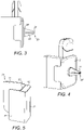
Figure 3 is a side view of the holder ofFigure 1 ; -
Figure 4 is a perspective view of the holder ofFigure 1 ; -
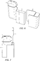
Figure 5 is a perspective view of a holder according to a second aspect of the present invention; -
Figure 6 is a perspective view of the holder ofFigure 5 with consumer articles; -
Figure 7 is a perspective view of the holder ofFigure 5 with a first article insertion configuration; -
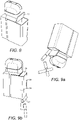
Figure 8 is a perspective view of the holder ofFigure 5 with a second article insertion configuration; -
Figure 9a is a perspective view of the holder ofFigure 8 ejecting consumer articles, andFigure 9b is a perspective view of the holder ofFigure 7 ejecting consumer articles. -
Figure 1 shows a schematic representation of a holder according to a first aspect of the present invention. Theholder 10 is formed of aback wall 3, a first side wall 1, anintermediate wall 2, a second side wall 4 and abase wall 16. Each of the first side wall 1, theintermediate side wall 2, the second side wall 4 and thebase wall 16 extend perpendicularly forwards from afront face 12 of theback wall 3. Thebase wall 16 is connected to the first side wall 1 at arounded corner 8. Thebase wall 16 extends perpendicular to the first side wall 1. - The first side wall 1, second side wall 4 and
intermediate wall 2 are positioned parallel to each other, with each wall extending substantially vertically. The first side wall 1 is positioned along one edge of theback wall 3. The second side wall 4 is positioned along an edge of theback wall 3 opposite the first side wall. Thebase wall 16 is positioned along an edge of theback wall 3 that extends between the first side wall 1 and the second side wall 4. - The first side wall 1,
intermediate wall 2 andbase wall 16 together with theback wall 3 define a first holding region. The second side wall 4 andintermediate wall 2 together with theback wall 3 define a second holding region. The first side wall 1 includes alip 14 extending along an inner face of the front edge of the first side wall 1 and projecting towards theintermediate wall 2. -
Figure 2a shows a perspective view of an aerosol-generatingdevice 5 held within the first holding region of theholder 10. The aerosol-generatingdevice 5 abuts each of the first side wall 1,intermediate wall 2 and thebase wall 16 as well as theback wall 3 in order to be retained on theholder 10 by interference fit. Additionally, the aerosol-generatingdevice 5 is positioned between thelip 14 and theback wall 3. Thelip 14 prevents the aerosol-generatingdevice 5 from falling forwards out of theholder 10. -
Figure 2b shows a packet of aerosol-generatingarticles 6 held within the second holding region of theholder 10. The packet of aerosol-generatingdevices 6 abuts each of the second side wall 4 and theintermediate side wall 2 in order to be retained on theholder 10 by interference fit. -
Figure 3 shows a side view of theholder 10 including an aerosol-generatingdevice 5 and a packet of aerosol-generatingarticles 6. Extending from a back face 18 of theback wall 3 is anattachment mechanism 20. Theattachment mechanism 20 extends perpendicularly outwards from the back face 18back wall 3. Theattachment mechanism 20 is formed of twoparallel projections 22 and 22' defining agroove 24 between the twoprojections 22 and 22'. The twoprojections 22 and 22' are joined at thebase 26 of theattachment mechanism 20. Thebase 26 of theattachment mechanism 20 has a large surface area. Thebase 26 of theattachment mechanism 20 connects to the back face 18back wall 3 of theholder 10, as shown inFigure 4 . Each of the twoprojections 22 and 22' taper away from the base 26 such that the projections are narrow at thetips 28. - The
attachment mechanism 20 is configured to attach to the air vents of vehicles in particular. A flap of an air vent can be received in thegroove 24 in order to position theholder 10 on the dashboard of a vehicle. -
Figure 5 shows aholder 30 according to a second aspect of the present invention. Theholder 30 is formed of aback wall 33, afirst side wall 31, asecond side wall 34 and areceptacle 32. Thefirst side wall 31 and thesecond side wall 34 extend perpendicularly from a first face of theback wall 33. Thefirst side wall 31 and thesecond side wall 34 are positioned parallel to each other, with each side wall extending substantially vertically. Thefirst side wall 31 is positioned along one edge of theback wall 33. Thesecond side wall 34 is positioned along an edge of theback wall 33 opposite the first side wall. - The
receptacle 32 is positioned on a second face of theback wall 33, opposite the first face. Thereceptacle 32 extends across the whole of the second face of theback wall 33. Thereceptacle 32 is defined by two opposingside walls 35, aback wall 36, atop cover 39 and a bottom wall 40. - As shown in
Figure 6 , an aerosol-generatingdevice 5 and a packet of aerosol-generatingarticles 6 are inserted into the holder by sliding from the distal edge of thefirst side wall 31 to theback wall 33. The aerosol-generatingdevice 5 and packet of aerosol-generatingarticles 6 are then held simultaneously between thefirst side wall 31 and thesecond side wall 34. The width of the aerosol-generatingdevice 5 and the packet of aerosol-generatingarticles 6 together is substantially equal to the distance between thefirst side wall 31 and thesecond side wall 34, such that the aerosol-generatingdevice 5 and the packet of aerosol-generatingarticles 6 are held in position via interference fit. - An
opening 42 is located within thetop cover 39 of thereceptacle 32. Theopening 42 is defined by two slits extending through thetop cover 39. The slits overlie each other and one slit is perpendicular to the other slit such that the two slits together form a cross. Thetop cover 39 surrounding the cross is formed of a resiliently deformable material. With this construction, a waste item, such as a used aerosol-generating article, may be pushed through theopening 42, as shown inFigure 7 , deforming the material either side of the slits, in order to enter thereceptacle 32. Once the article is inserted, the material either side of the slits will return to its original position such that the waste and any odours generated by it are prevented from escaping from thereceptacle 32. - In an alternative embodiment, as shown in
Figure 8 , thetop cover 39 may be hingedly connected to the second face of theback wall 33. Thetop cover 39 in this embodiment may be opened by a user to allow waste consumer articles to be inserted into thereceptacle 32. In order to empty the contents of thereceptacle 32, thetop cover 39 may be opened and theholder 30 tipped in order that the consumer articles within thereceptacle 32 can fall out, as shown inFigure 9a . - In the first embodiment, in which the
top cover 39 is fixedly attached to the main body of thereceptacle 32, the bottom wall 40 includes an aperture 46 to allow the contents of thereceptacle 32 to be removed. Waste aerosol-generating articles can be ejected through the aperture 46 at a convenient time. The aperture 46 is covered by a hingedlid 44 as shown inFigures 9a and 9b . The hingedlid 44 has a locking means to retain the hingedlid 44 in a closed position such that it covers theaperture 42. A user may activate the locking means in order to open the hingedlid 44 such that waste can be emptied from thereceptacle 32.
Claims (12)
- A holder (30) for holding an aerosol-generating device (5) and a packet of aerosol-generating articles (6), the holder (30) comprising;a back wall (33), a support structure mounted on a first face of the back wall (33), and a receptacle (32) mounted on a second face of the back wall (33), wherein the first face is opposite the second face;the support structure comprisinga first side wall (31) projecting from the first face of the back wall (33);a second side wall (34) projecting from the first face of the back wall (33), wherein the second side wall (34) is positioned opposite the first side wall (31) and is separated from the first side wall (31) by a predetermined distance such that the first and second side walls (31, 34) are configured to hold the aerosol-generating device (5) and the packet of aerosol-generating articles (6) by interference fit, and wherein the first side wall (31) projects further from the back wall (33) than the second side wall (34) projects from the back wall (33); andthe receptacle (32) defining one or more compartments.
- The holder (30) of claim 1, wherein the receptacle (32) comprises a main body having a closed bottom end and an open top end.
- The holder (30) of claim 2, wherein the receptacle (32) comprises a lid (39) configured to cover the open top end.
- The holder (30) of claim 3, wherein the lid (39) is a hinged lid.
- The holder (30) of claim 2, wherein the receptacle (32) comprises a cover (39) over the open top end, and the cover (39) includes a region of resiliently deformable material, the region of resiliently deformable material including at least one slit extending through the resiliently deformable material.
- The holder (30) of claim 5, wherein the at least one slit comprises two slits extending through the resiliently deformable material, the two slits overlying each other to define a cross shape.
- The holder (30) of any of claims 2 to 6, wherein the receptacle (32) comprises an aperture (46) in the bottom end and a flap (44) configured to cover the aperture (46).
- A holder (10) for holding an aerosol-generating device (5) and a packet of aerosol-generating articles (6), the holder (10) comprising;a back wall (3) and a support structure mounted on a front face of the back wall (3);the support structure comprising;a first side wall (1) projecting from the front face of the back wall (3);a second side wall (4) projecting from the front face of the back wall (3), the second side wall (4) positioned opposite the first side wall (1);a base wall (16) projecting from the front face of the back wall (3), and positioned proximate the first side wall (1), wherein the base wall (16) is configured to support one or more of the aerosol-generating device (5) and the packet of aerosol-generating articles (6); andan intermediate wall (2) projecting from the front face of the back wall (3), the intermediate wall (2) positioned between the first and second side walls (1, 4), wherein the intermediate wall (2) is separated from the first side wall (1) by a first predetermined distance such that the intermediate and first side walls (1, 2) are configured to hold the aerosol-generating device (5) by interference fit, and the intermediate wall (2) is separated from the second side wall (4) by a second predetermined distance such that the intermediate and second side walls (2, 4) are configured to hold the packet of aerosol-generating articles (6) by interference fit, wherein the first side wall (1) comprises a back edge adjacent to the back wall (3) and a front edge opposite the back edge, the first side wall (1) further comprising a projection, the projection positioned adjacent the front edge of the first side wall (1) and directed towards the intermediate wall (2), the projection configured to retain the aerosol-generating device (5) between the first side wall (1) and intermediate wall (2), wherein the projection of the first side wall (1) is elongate and extends parallel to the front edge of the first side wall (1).
- The holder (10) of claim 8, wherein the first side wall (1) and the base wall (16) of the support structure are connected at a corner (8) of the back wall (3) such that the first side wall (1) and the base wall (3) together form a seat for the aerosol-generating device (5).
- The holder (10) of claim 8 or 9, wherein the first predetermined distance is such that the holder (10) is adapted to hold the aerosol-generating device (5) with the widest side of the aerosol-generating device (5) adjacent the back wall (3).
- The holder (10) of claim 8 or 9, wherein the first predetermined distance is such that the holder (10) is adapted to hold the aerosol-generating device (5) with the narrowest side of the aerosol-generating article (6) adjacent the back wall (30).
- The holder (10) of any of claims 8 to 11, further comprising an attachment mechanism (20) on a back face (18) of the back wall (3), the back face (18) opposite the front face.
Applications Claiming Priority (2)
| Application Number | Priority Date | Filing Date | Title |
|---|---|---|---|
| EP17210856 | 2017-12-28 | ||
| PCT/EP2018/086844 WO2019129764A2 (en) | 2017-12-28 | 2018-12-24 | A holder for two or more consumer articles |
Publications (2)
| Publication Number | Publication Date |
|---|---|
| EP3732077A2 EP3732077A2 (en) | 2020-11-04 |
| EP3732077B1 true EP3732077B1 (en) | 2022-06-08 |
Family
ID=60813733
Family Applications (1)
| Application Number | Title | Priority Date | Filing Date |
|---|---|---|---|
| EP18826396.6A Active EP3732077B1 (en) | 2017-12-28 | 2018-12-24 | A holder for holding an aerosol-generating device and a packet of aerosol-generating articles |
Country Status (8)
| Country | Link |
|---|---|
| US (1) | US20210068453A1 (en) |
| EP (1) | EP3732077B1 (en) |
| JP (1) | JP7414719B2 (en) |
| KR (1) | KR102684902B1 (en) |
| CN (1) | CN111448101B (en) |
| BR (1) | BR112020010190B1 (en) |
| RU (1) | RU2762971C1 (en) |
| WO (1) | WO2019129764A2 (en) |
Families Citing this family (1)
| Publication number | Priority date | Publication date | Assignee | Title |
|---|---|---|---|---|
| WO2023012362A2 (en) * | 2021-08-05 | 2023-02-09 | Philip Morris Products S.A. | Container having a mounting mechanism |
Citations (1)
| Publication number | Priority date | Publication date | Assignee | Title |
|---|---|---|---|---|
| USD750612S1 (en) * | 2014-05-26 | 2016-03-01 | Ko-An Chen | Car air vent mount holder for cellphones |
Family Cites Families (30)
| Publication number | Priority date | Publication date | Assignee | Title |
|---|---|---|---|---|
| JPS4124296Y1 (en) * | 1965-05-12 | 1966-12-10 | ||
| US3986649A (en) * | 1973-11-19 | 1976-10-19 | Heimstra Frederick A | Suspended storage device |
| JPS53122265U (en) * | 1977-03-05 | 1978-09-28 | ||
| FR2403755A1 (en) * | 1977-09-21 | 1979-04-20 | Aerflam Srl | POCKET ACCESSORY FOR SMOKERS CONSTITUTED BY A JUNCTION BODY ALLOWING TO ASSOCIATE A PACK OF CIGARETTES OR SIMILAR WITH A LIGHTER |
| JPS62107254U (en) * | 1985-12-16 | 1987-07-09 | ||
| US4852729A (en) * | 1988-03-01 | 1989-08-01 | Conte John R | Cigarette-lighter holder |
| JPH0263695U (en) * | 1988-11-04 | 1990-05-14 | ||
| JPH0660398U (en) * | 1993-02-01 | 1994-08-23 | 真史 藤田 | Cigarette and igniter holder |
| JP3005730U (en) | 1994-06-28 | 1995-01-10 | レック株式会社 | Hanging hanger with pen holder |
| JPH10281467A (en) * | 1997-04-04 | 1998-10-23 | Hidemasa Matano | Metallic fastener for cigarette package and lighter |
| US5918734A (en) * | 1997-08-04 | 1999-07-06 | Devens; C. Scott | Cigarette packaging with integral lighter receptacle |
| JPH11141875A (en) * | 1997-11-11 | 1999-05-28 | Seiko Kogyo Kk | Lighter with cutter device for cigar |
| KR200176276Y1 (en) * | 1999-10-06 | 2000-03-15 | 주식회사비룡화학 | Case for the pack of cigarettes |
| US6430782B1 (en) * | 2000-06-28 | 2002-08-13 | David Torres | Cigarette lighter clip |
| US6693850B2 (en) | 2001-10-03 | 2004-02-17 | Azanaw Mulaw | Cigarette case with lighter and clock |
| US20050100847A1 (en) * | 2003-11-10 | 2005-05-12 | Wen-Cheng Chung | Lighter case attachable to a cigarette pack |
| WO2006012753A1 (en) * | 2004-08-04 | 2006-02-09 | Taketray Gmbh | Portable container for the ecological disposal of problematic small wastes |
| CN200966312Y (en) * | 2006-11-03 | 2007-10-31 | 张志明 | Environment-protecting type multifunctional cigarette (tool) box |
| KR20100000905A (en) * | 2008-06-26 | 2010-01-06 | 이종협 | Tobacco case |
| KR20100077079A (en) * | 2008-12-27 | 2010-07-07 | 윤슬기 | Tobacco case |
| EP2454956A1 (en) | 2010-11-19 | 2012-05-23 | Philip Morris Products S.A. | An electrically heated smoking system comprising at least two units |
| US20130200124A1 (en) * | 2012-02-03 | 2013-08-08 | Bur-Nie Industries, Llc | Condiment holder for vehicles |
| CN103844356A (en) * | 2014-01-11 | 2014-06-11 | 杨永康 | Cigarette lighter clamp |
| US9602646B2 (en) * | 2014-01-29 | 2017-03-21 | Vaportronix Llc | Combination mobile phone case and electronic cigarette |
| CN103802712A (en) * | 2014-02-27 | 2014-05-21 | 范绍明 | Vehicle-mounted cigarette lighting device |
| CN203986088U (en) * | 2014-06-09 | 2014-12-10 | 广东中烟工业有限责任公司 | A kind of stub treating apparatus cigarette case that is provided with |
| CN204483013U (en) * | 2014-09-11 | 2015-07-22 | 王金海 | Combination cigarette case |
| KR200483697Y1 (en) * | 2016-06-10 | 2017-06-14 | 이문희 | Holder for a cigar box and a lighter |
| KR200484634Y1 (en) * | 2016-06-10 | 2017-10-10 | 이문희 | Holder for a cigar box and a lighter |
| JP3211659U (en) | 2017-05-16 | 2017-07-27 | 豊 榊田 | Smoking case equipment |
-
2018
- 2018-12-24 JP JP2020534441A patent/JP7414719B2/en active Active
- 2018-12-24 CN CN201880078717.4A patent/CN111448101B/en active Active
- 2018-12-24 KR KR1020207019110A patent/KR102684902B1/en active Active
- 2018-12-24 BR BR112020010190-7A patent/BR112020010190B1/en active IP Right Grant
- 2018-12-24 WO PCT/EP2018/086844 patent/WO2019129764A2/en not_active Ceased
- 2018-12-24 EP EP18826396.6A patent/EP3732077B1/en active Active
- 2018-12-24 US US16/958,363 patent/US20210068453A1/en not_active Abandoned
- 2018-12-24 RU RU2020122695A patent/RU2762971C1/en active
Patent Citations (1)
| Publication number | Priority date | Publication date | Assignee | Title |
|---|---|---|---|---|
| USD750612S1 (en) * | 2014-05-26 | 2016-03-01 | Ko-An Chen | Car air vent mount holder for cellphones |
Also Published As
| Publication number | Publication date |
|---|---|
| KR102684902B1 (en) | 2024-07-15 |
| KR20200100093A (en) | 2020-08-25 |
| BR112020010190B1 (en) | 2023-11-21 |
| WO2019129764A3 (en) | 2019-08-01 |
| JP2021509263A (en) | 2021-03-25 |
| EP3732077A2 (en) | 2020-11-04 |
| US20210068453A1 (en) | 2021-03-11 |
| CN111448101A (en) | 2020-07-24 |
| BR112020010190A2 (en) | 2020-11-03 |
| JP7414719B2 (en) | 2024-01-16 |
| WO2019129764A2 (en) | 2019-07-04 |
| CN111448101B (en) | 2023-01-24 |
| RU2762971C1 (en) | 2021-12-24 |
Similar Documents
| Publication | Publication Date | Title |
|---|---|---|
| CN205700927U (en) | Tobacco grinding device | |
| US5630503A (en) | Combination cigarette pack and lighter holder | |
| US20060243611A1 (en) | Cigarette package | |
| EP1078594A1 (en) | Flat article dispensing device | |
| HUP0400158A2 (en) | A box with a flapping lid | |
| US20020000389A1 (en) | Packaging system with a receptacle for storing debris | |
| JP2001511368A (en) | Cigarette lighter case | |
| US20210068453A1 (en) | A holder for holding an aerosol-generating device and a packet of aerosol-generating articles | |
| KR102708931B1 (en) | Containers for consumer goods including means of dispensing | |
| US6138822A (en) | Cigarette packaging system with an ashtray unit | |
| JP7417518B2 (en) | Receptacle for aerosol generating articles | |
| EP2404514A1 (en) | Package, in particular for smoking articles | |
| WO2008146175A2 (en) | Package with tray enclosure | |
| EP3727939B1 (en) | Container with support means | |
| US20020020640A1 (en) | Packaging system with a receptacle for storing debris | |
| JP2021506680A (en) | Child resistant container | |
| US20120247997A1 (en) | Chewing gum cover with wrapper pocket | |
| BR112020002653B1 (en) | RECEPTACLE FOR STORAGE OF ONE OR MORE AEROSOL GENERATOR ARTICLES AND KIT | |
| HK1160741A (en) | Package, in particular for smoking articles | |
| JPH0518977U (en) | Car accessory tray |
Legal Events
| Date | Code | Title | Description |
|---|---|---|---|
| STAA | Information on the status of an ep patent application or granted ep patent |
Free format text: STATUS: UNKNOWN |
|
| STAA | Information on the status of an ep patent application or granted ep patent |
Free format text: STATUS: THE INTERNATIONAL PUBLICATION HAS BEEN MADE |
|
| PUAI | Public reference made under article 153(3) epc to a published international application that has entered the european phase |
Free format text: ORIGINAL CODE: 0009012 |
|
| STAA | Information on the status of an ep patent application or granted ep patent |
Free format text: STATUS: REQUEST FOR EXAMINATION WAS MADE |
|
| 17P | Request for examination filed |
Effective date: 20200611 |
|
| AK | Designated contracting states |
Kind code of ref document: A2 Designated state(s): AL AT BE BG CH CY CZ DE DK EE ES FI FR GB GR HR HU IE IS IT LI LT LU LV MC MK MT NL NO PL PT RO RS SE SI SK SM TR |
|
| AX | Request for extension of the european patent |
Extension state: BA ME |
|
| DAV | Request for validation of the european patent (deleted) | ||
| DAX | Request for extension of the european patent (deleted) | ||
| GRAP | Despatch of communication of intention to grant a patent |
Free format text: ORIGINAL CODE: EPIDOSNIGR1 |
|
| STAA | Information on the status of an ep patent application or granted ep patent |
Free format text: STATUS: GRANT OF PATENT IS INTENDED |
|
| INTG | Intention to grant announced |
Effective date: 20211215 |
|
| GRAS | Grant fee paid |
Free format text: ORIGINAL CODE: EPIDOSNIGR3 |
|
| GRAA | (expected) grant |
Free format text: ORIGINAL CODE: 0009210 |
|
| STAA | Information on the status of an ep patent application or granted ep patent |
Free format text: STATUS: THE PATENT HAS BEEN GRANTED |
|
| AK | Designated contracting states |
Kind code of ref document: B1 Designated state(s): AL AT BE BG CH CY CZ DE DK EE ES FI FR GB GR HR HU IE IS IT LI LT LU LV MC MK MT NL NO PL PT RO RS SE SI SK SM TR |
|
| REG | Reference to a national code |
Ref country code: AT Ref legal event code: REF Ref document number: 1496711 Country of ref document: AT Kind code of ref document: T Effective date: 20220615 Ref country code: CH Ref legal event code: EP |
|
| REG | Reference to a national code |
Ref country code: DE Ref legal event code: R096 Ref document number: 602018036598 Country of ref document: DE |
|
| REG | Reference to a national code |
Ref country code: IE Ref legal event code: FG4D |
|
| REG | Reference to a national code |
Ref country code: NL Ref legal event code: FP |
|
| REG | Reference to a national code |
Ref country code: LT Ref legal event code: MG9D |
|
| PG25 | Lapsed in a contracting state [announced via postgrant information from national office to epo] |
Ref country code: SE Free format text: LAPSE BECAUSE OF FAILURE TO SUBMIT A TRANSLATION OF THE DESCRIPTION OR TO PAY THE FEE WITHIN THE PRESCRIBED TIME-LIMIT Effective date: 20220608 Ref country code: NO Free format text: LAPSE BECAUSE OF FAILURE TO SUBMIT A TRANSLATION OF THE DESCRIPTION OR TO PAY THE FEE WITHIN THE PRESCRIBED TIME-LIMIT Effective date: 20220908 Ref country code: LT Free format text: LAPSE BECAUSE OF FAILURE TO SUBMIT A TRANSLATION OF THE DESCRIPTION OR TO PAY THE FEE WITHIN THE PRESCRIBED TIME-LIMIT Effective date: 20220608 Ref country code: HR Free format text: LAPSE BECAUSE OF FAILURE TO SUBMIT A TRANSLATION OF THE DESCRIPTION OR TO PAY THE FEE WITHIN THE PRESCRIBED TIME-LIMIT Effective date: 20220608 Ref country code: GR Free format text: LAPSE BECAUSE OF FAILURE TO SUBMIT A TRANSLATION OF THE DESCRIPTION OR TO PAY THE FEE WITHIN THE PRESCRIBED TIME-LIMIT Effective date: 20220909 Ref country code: FI Free format text: LAPSE BECAUSE OF FAILURE TO SUBMIT A TRANSLATION OF THE DESCRIPTION OR TO PAY THE FEE WITHIN THE PRESCRIBED TIME-LIMIT Effective date: 20220608 Ref country code: BG Free format text: LAPSE BECAUSE OF FAILURE TO SUBMIT A TRANSLATION OF THE DESCRIPTION OR TO PAY THE FEE WITHIN THE PRESCRIBED TIME-LIMIT Effective date: 20220908 |
|
| REG | Reference to a national code |
Ref country code: AT Ref legal event code: MK05 Ref document number: 1496711 Country of ref document: AT Kind code of ref document: T Effective date: 20220608 |
|
| PG25 | Lapsed in a contracting state [announced via postgrant information from national office to epo] |
Ref country code: RS Free format text: LAPSE BECAUSE OF FAILURE TO SUBMIT A TRANSLATION OF THE DESCRIPTION OR TO PAY THE FEE WITHIN THE PRESCRIBED TIME-LIMIT Effective date: 20220608 Ref country code: LV Free format text: LAPSE BECAUSE OF FAILURE TO SUBMIT A TRANSLATION OF THE DESCRIPTION OR TO PAY THE FEE WITHIN THE PRESCRIBED TIME-LIMIT Effective date: 20220608 |
|
| PG25 | Lapsed in a contracting state [announced via postgrant information from national office to epo] |
Ref country code: SM Free format text: LAPSE BECAUSE OF FAILURE TO SUBMIT A TRANSLATION OF THE DESCRIPTION OR TO PAY THE FEE WITHIN THE PRESCRIBED TIME-LIMIT Effective date: 20220608 Ref country code: SK Free format text: LAPSE BECAUSE OF FAILURE TO SUBMIT A TRANSLATION OF THE DESCRIPTION OR TO PAY THE FEE WITHIN THE PRESCRIBED TIME-LIMIT Effective date: 20220608 Ref country code: RO Free format text: LAPSE BECAUSE OF FAILURE TO SUBMIT A TRANSLATION OF THE DESCRIPTION OR TO PAY THE FEE WITHIN THE PRESCRIBED TIME-LIMIT Effective date: 20220608 Ref country code: PT Free format text: LAPSE BECAUSE OF FAILURE TO SUBMIT A TRANSLATION OF THE DESCRIPTION OR TO PAY THE FEE WITHIN THE PRESCRIBED TIME-LIMIT Effective date: 20221010 Ref country code: ES Free format text: LAPSE BECAUSE OF FAILURE TO SUBMIT A TRANSLATION OF THE DESCRIPTION OR TO PAY THE FEE WITHIN THE PRESCRIBED TIME-LIMIT Effective date: 20220608 Ref country code: EE Free format text: LAPSE BECAUSE OF FAILURE TO SUBMIT A TRANSLATION OF THE DESCRIPTION OR TO PAY THE FEE WITHIN THE PRESCRIBED TIME-LIMIT Effective date: 20220608 Ref country code: CZ Free format text: LAPSE BECAUSE OF FAILURE TO SUBMIT A TRANSLATION OF THE DESCRIPTION OR TO PAY THE FEE WITHIN THE PRESCRIBED TIME-LIMIT Effective date: 20220608 Ref country code: AT Free format text: LAPSE BECAUSE OF FAILURE TO SUBMIT A TRANSLATION OF THE DESCRIPTION OR TO PAY THE FEE WITHIN THE PRESCRIBED TIME-LIMIT Effective date: 20220608 |
|
| PG25 | Lapsed in a contracting state [announced via postgrant information from national office to epo] |
Ref country code: PL Free format text: LAPSE BECAUSE OF FAILURE TO SUBMIT A TRANSLATION OF THE DESCRIPTION OR TO PAY THE FEE WITHIN THE PRESCRIBED TIME-LIMIT Effective date: 20220608 Ref country code: IS Free format text: LAPSE BECAUSE OF FAILURE TO SUBMIT A TRANSLATION OF THE DESCRIPTION OR TO PAY THE FEE WITHIN THE PRESCRIBED TIME-LIMIT Effective date: 20221008 |
|
| REG | Reference to a national code |
Ref country code: DE Ref legal event code: R097 Ref document number: 602018036598 Country of ref document: DE |
|
| PG25 | Lapsed in a contracting state [announced via postgrant information from national office to epo] |
Ref country code: AL Free format text: LAPSE BECAUSE OF FAILURE TO SUBMIT A TRANSLATION OF THE DESCRIPTION OR TO PAY THE FEE WITHIN THE PRESCRIBED TIME-LIMIT Effective date: 20220608 |
|
| PLBE | No opposition filed within time limit |
Free format text: ORIGINAL CODE: 0009261 |
|
| STAA | Information on the status of an ep patent application or granted ep patent |
Free format text: STATUS: NO OPPOSITION FILED WITHIN TIME LIMIT |
|
| PG25 | Lapsed in a contracting state [announced via postgrant information from national office to epo] |
Ref country code: DK Free format text: LAPSE BECAUSE OF FAILURE TO SUBMIT A TRANSLATION OF THE DESCRIPTION OR TO PAY THE FEE WITHIN THE PRESCRIBED TIME-LIMIT Effective date: 20220608 |
|
| 26N | No opposition filed |
Effective date: 20230310 |
|
| PG25 | Lapsed in a contracting state [announced via postgrant information from national office to epo] |
Ref country code: SI Free format text: LAPSE BECAUSE OF FAILURE TO SUBMIT A TRANSLATION OF THE DESCRIPTION OR TO PAY THE FEE WITHIN THE PRESCRIBED TIME-LIMIT Effective date: 20220608 |
|
| P01 | Opt-out of the competence of the unified patent court (upc) registered |
Effective date: 20230529 |
|
| REG | Reference to a national code |
Ref country code: BE Ref legal event code: MM Effective date: 20221231 |
|
| PG25 | Lapsed in a contracting state [announced via postgrant information from national office to epo] |
Ref country code: LU Free format text: LAPSE BECAUSE OF NON-PAYMENT OF DUE FEES Effective date: 20221224 |
|
| PG25 | Lapsed in a contracting state [announced via postgrant information from national office to epo] |
Ref country code: IE Free format text: LAPSE BECAUSE OF NON-PAYMENT OF DUE FEES Effective date: 20221224 |
|
| PG25 | Lapsed in a contracting state [announced via postgrant information from national office to epo] |
Ref country code: BE Free format text: LAPSE BECAUSE OF NON-PAYMENT OF DUE FEES Effective date: 20221231 |
|
| PG25 | Lapsed in a contracting state [announced via postgrant information from national office to epo] |
Ref country code: CY Free format text: LAPSE BECAUSE OF FAILURE TO SUBMIT A TRANSLATION OF THE DESCRIPTION OR TO PAY THE FEE WITHIN THE PRESCRIBED TIME-LIMIT Effective date: 20220608 |
|
| PG25 | Lapsed in a contracting state [announced via postgrant information from national office to epo] |
Ref country code: MK Free format text: LAPSE BECAUSE OF FAILURE TO SUBMIT A TRANSLATION OF THE DESCRIPTION OR TO PAY THE FEE WITHIN THE PRESCRIBED TIME-LIMIT Effective date: 20220608 Ref country code: HU Free format text: LAPSE BECAUSE OF FAILURE TO SUBMIT A TRANSLATION OF THE DESCRIPTION OR TO PAY THE FEE WITHIN THE PRESCRIBED TIME-LIMIT; INVALID AB INITIO Effective date: 20181224 |
|
| PG25 | Lapsed in a contracting state [announced via postgrant information from national office to epo] |
Ref country code: MC Free format text: LAPSE BECAUSE OF FAILURE TO SUBMIT A TRANSLATION OF THE DESCRIPTION OR TO PAY THE FEE WITHIN THE PRESCRIBED TIME-LIMIT Effective date: 20220608 |
|
| PG25 | Lapsed in a contracting state [announced via postgrant information from national office to epo] |
Ref country code: TR Free format text: LAPSE BECAUSE OF FAILURE TO SUBMIT A TRANSLATION OF THE DESCRIPTION OR TO PAY THE FEE WITHIN THE PRESCRIBED TIME-LIMIT Effective date: 20220608 Ref country code: MC Free format text: LAPSE BECAUSE OF FAILURE TO SUBMIT A TRANSLATION OF THE DESCRIPTION OR TO PAY THE FEE WITHIN THE PRESCRIBED TIME-LIMIT Effective date: 20220608 |
|
| PG25 | Lapsed in a contracting state [announced via postgrant information from national office to epo] |
Ref country code: MT Free format text: LAPSE BECAUSE OF FAILURE TO SUBMIT A TRANSLATION OF THE DESCRIPTION OR TO PAY THE FEE WITHIN THE PRESCRIBED TIME-LIMIT Effective date: 20220608 |
|
| PG25 | Lapsed in a contracting state [announced via postgrant information from national office to epo] |
Ref country code: BG Free format text: LAPSE BECAUSE OF FAILURE TO SUBMIT A TRANSLATION OF THE DESCRIPTION OR TO PAY THE FEE WITHIN THE PRESCRIBED TIME-LIMIT Effective date: 20220608 |
|
| PG25 | Lapsed in a contracting state [announced via postgrant information from national office to epo] |
Ref country code: BG Free format text: LAPSE BECAUSE OF FAILURE TO SUBMIT A TRANSLATION OF THE DESCRIPTION OR TO PAY THE FEE WITHIN THE PRESCRIBED TIME-LIMIT Effective date: 20220608 |
|
| REG | Reference to a national code |
Ref country code: CH Ref legal event code: U11 Free format text: ST27 STATUS EVENT CODE: U-0-0-U10-U11 (AS PROVIDED BY THE NATIONAL OFFICE) Effective date: 20260101 |
|
| PGFP | Annual fee paid to national office [announced via postgrant information from national office to epo] |
Ref country code: DE Payment date: 20251211 Year of fee payment: 8 |
|
| PGFP | Annual fee paid to national office [announced via postgrant information from national office to epo] |
Ref country code: GB Payment date: 20251219 Year of fee payment: 8 |
|
| PGFP | Annual fee paid to national office [announced via postgrant information from national office to epo] |
Ref country code: IT Payment date: 20251222 Year of fee payment: 8 |
|
| PGFP | Annual fee paid to national office [announced via postgrant information from national office to epo] |
Ref country code: NL Payment date: 20251219 Year of fee payment: 8 Ref country code: FR Payment date: 20251229 Year of fee payment: 8 |
|
| PGFP | Annual fee paid to national office [announced via postgrant information from national office to epo] |
Ref country code: CH Payment date: 20260101 Year of fee payment: 8 |