EP3731616A1 - Tape feeder - Google Patents
Tape feeder Download PDFInfo
- Publication number
- EP3731616A1 EP3731616A1 EP17935787.6A EP17935787A EP3731616A1 EP 3731616 A1 EP3731616 A1 EP 3731616A1 EP 17935787 A EP17935787 A EP 17935787A EP 3731616 A1 EP3731616 A1 EP 3731616A1
- Authority
- EP
- European Patent Office
- Prior art keywords
- tape
- width
- section
- conveyance path
- feeder
- Prior art date
- Legal status (The legal status is an assumption and is not a legal conclusion. Google has not performed a legal analysis and makes no representation as to the accuracy of the status listed.)
- Granted
Links
Images




Classifications
-
- H—ELECTRICITY
- H05—ELECTRIC TECHNIQUES NOT OTHERWISE PROVIDED FOR
- H05K—PRINTED CIRCUITS; CASINGS OR CONSTRUCTIONAL DETAILS OF ELECTRIC APPARATUS; MANUFACTURE OF ASSEMBLAGES OF ELECTRICAL COMPONENTS
- H05K13/00—Apparatus or processes specially adapted for manufacturing or adjusting assemblages of electric components
- H05K13/04—Mounting of components, e.g. of leadless components
- H05K13/0417—Feeding with belts or tapes
- H05K13/0419—Feeding with belts or tapes tape feeders
-
- H—ELECTRICITY
- H05—ELECTRIC TECHNIQUES NOT OTHERWISE PROVIDED FOR
- H05K—PRINTED CIRCUITS; CASINGS OR CONSTRUCTIONAL DETAILS OF ELECTRIC APPARATUS; MANUFACTURE OF ASSEMBLAGES OF ELECTRICAL COMPONENTS
- H05K13/00—Apparatus or processes specially adapted for manufacturing or adjusting assemblages of electric components
- H05K13/02—Feeding of components
Definitions
- the present disclosure relates to a tape feeder for supplying electronic components to an electronic component mounting machine.
- a tape feeder is provided with a conveyance path for feeding tape containing electronic components.
- the tape is conveyed through the conveyance path by the sprockets.
- the extraction position of the electronic component is set.
- a suction nozzle of the electronic component mounting machine conveys the electronic component from the extraction position to a predetermined coordinate on a board.
- Patent Literature 1 discloses an electronic component supply device including a tape holding member.
- the tape holding member has a leaf spring shape.
- the tape holding member is in elastic contact with the side face of the tape in the path width direction.
- the tape is offset in the path width direction by the tape holding member. Therefore, according to the electronic component supply device of Patent Literature 1, it is possible to suppress the deviation of the tape in the path width direction.
- Patent Literature 1 JP-A-2000-40897
- an object of the present disclosure is to provide a tape feeder capable of partially adjusting a path width of a conveyance path.
- a tape feeder including: a feeder main body including a conveyance path through which a tape having electronic components accommodated therein is conveyed and which has a base width section wider than the tape and a narrow width section narrower than the base width section; and a width regulating section that abuts against the tape conveyed through the conveyance path from a path width direction of the conveyance path so as to set the narrow width section on the conveyance path.
- the "path width direction” means a direction intersecting with the extending direction of the conveyance path.
- the conveyance path of the tape feeder has the base width section and the narrow width section.
- the base width section is wider than the tape. Therefore, the tape can be smoothly conveyed.
- the narrow width section is narrower than the base width section. Therefore, it is possible to suppress the deviation of the tape in the path width direction.
- the front-rear direction corresponds to the "path length direction” in the present disclosure
- the left-right direction corresponds to the "path width direction” in the present disclosure, respectively.
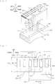
- Fig. 1 illustrates a top view of the tape feeder of the present embodiment.
- Fig. 2 illustrates a transmission right view of the same tape feeder.
- Fig. 3 illustrates an enlarged view of a frame III of Fig. 1 .
- Fig. 4 illustrates a perspective view of the frame III.
- Fig. 5 illustrates an exploded perspective view of the frame III.
- Tape feeder 1 is exchangeably disposed in an electronic component mounting machine (not illustrated). Tape feeder 1 includes feeder main body 2, width regulating block 3, tape 4, reel 5, reel holder 6, and sprocket 7.
- Feeder main body 2 has a narrow box shape that extends in the front-rear direction and the up-down direction.
- Feeder main body 2 includes conveyance path A, guide wall 20, and recessed portion 21. Conveyance path A, guide wall 20, recessed portion 21 are disposed on the upper face of feeder main body 2.
- Guide wall 20 is disposed along the right edge of the upper face of feeder main body 2. Guide wall 20 extends in the front-rear direction. Left face (the inner face in the path width direction) of guide wall 20 is guide section 200. Guide section 200 has a planar shape that extends in the front-rear direction and the up-down direction.
- Recessed portion 21 is recessed in the vicinity of the left edge of the upper face of feeder main body 2.
- Width regulating block 3 includes base section 30 and regulating section 31.
- Base section 30 has a cylindrical shape.
- Base section 30 is accommodated in recessed portion 21.
- Regulating section 31 is continuously formed on the upper side of base section 30.
- Regulating section 31 has a semicylindrical shape.
- Regulating section 31 protrudes from the upper face of feeder main body 2.
- Regulating section 31 includes abutting section 310.
- Abutting section 310 has a planar shape that extends in the front-rear direction and the up-down direction.
- Conveyance path A extends in the front-rear direction.
- extraction position B is set.
- electronic component P is extracted from component accommodation section 400 of tape 4 to be described later by a suction nozzle (not illustrated) of the electronic component mounting machine.
- the electronic component P that has been extracted is mounted with a predetermined mounting coordinate on the board (not illustrated).
- Recessed portion 21 is disposed in front of the extraction position B. Recessed portion 21 and extraction position B are arranged adjacent to each other in the front-rear direction. Specifically, as illustrated in Fig.
- interval C which is the distance between a pair of component accommodation sections 400 (specifically, the center of component accommodation section 400 in the front-rear direction) adjacent to each other in the front-rear direction.
- Conveyance path A includes base width section A1 and narrow width section A2.
- Narrow width section A2 is disposed between width regulating block 3 on the left side and guide wall 20 on the right side.
- the left edge of narrow width section A2 is defined by abutting section 310.
- the right edge of narrow width section A2 is defined by guide section 200.
- Base width section A1 is set at a part other than narrow width section A2 in conveyance path A.
- the left edge of base width section A1 is defined by the left edge of the upper face of feeder main body 2.
- the right edge of base width section A1 is defined by guide section 200.
- Sprocket 7 is accommodated inside feeder main body 2. Sprocket 7 is intermittently rotatable by a motor (not illustrated). Multiple teeth 70 are arranged at the outer peripheral edge of sprocket 7.
- Reel holder 6 is disposed on the rear side of feeder main body 2. Reel 5 is accommodated in reel holder 6, while being capable of being extracted.
- Tape 4 is wound around shaft section 50 of reel 5. Tape 4 is pulled out from the upper portion of reel 5 to the rear side. Tape 4 which has been pulled out extends in the front-rear direction along conveyance path A. Tape 4 includes carrier tape 40 and cover tape 41.
- Carrier tape 40 includes multiple component accommodation sections 400 and multiple feed holes 401.
- Multiple component accommodation sections 400 are each recessed on the upper face of carrier tape 40.
- Multiple component accommodation sections 400 are distanced from each other at predetermined intervals, and are arranged side by side in the front-rear direction (the longitudinal direction of carrier tape 40).
- electronic components P are accommodated.
- Multiple feed holes 401 each pass through carrier tape 40 in the up-down direction.
- Multiple feed holes 401 are distanced from each other at predetermined intervals, and are arranged side by side in the front-rear direction.
- Multiple feed holes 401 are arranged on the right side (one side of carrier tape 40 in the short direction) of multiple component accommodation sections 400.
- Cover tape 41 is laminated on the upper side (outer side in the radial direction in a state of being wound around reel 5) of carrier tape 40. Cover tape 41 seals multiple component accommodation sections 400 from the upper side.
- tape 4 is conveyed by sprocket 7.
- teeth 70 project from the upper face of feeder main body 2. Projecting teeth 70 mesh with feed holes 401 of tape 4. Subsequently, teeth 70 rotate from the front side toward the rear side. At this time, teeth 70 conveys feed hole 401, that is, tape 4, from the front side toward the rear side.
- conveyance path A has base width section A1 and narrow width section A2. Left-right direction width D1 of base width section A1 is wider than left-right direction width D3 of tape 4. Therefore, in base width section A1, tape 4 can be smoothly conveyed.
- Left-right direction width D2 of narrow width section A2 is narrower than left-right direction width D1 of base width section A1. Therefore, in narrow width section A2, the deviation (for example, meandering, curvature or the like) of tape 4 in the left-right direction can be suppressed. Suppressing the deviation of tape 4 in the left-right direction makes it possible to suppress the deviation of the actual position of electronic component P with respect to extraction position B in the left-right direction. Therefore, the deviation of the suction position of the suction nozzle with respect to electronic component P in the left-right direction can be suppressed.
- the deviation in the left-right direction between the center of gravity of the to-be-suctioned surface of electronic component P and the center of gravity of the nozzle tip of the suction nozzle can be suppressed. Accordingly, it is possible to improve the positional accuracy of electronic component P on the board.
- abutting section 310 is made of an elastic body (for example, rubber sponge or the like) (it is needless to say that an aspect in which abutting section 310 is made of an elastic body is also included in the present disclosure), there is a case where abutting section 310 is worn by sliding contact with carrier tape 40.
- width regulating block 3, that is, abutting section 310 is made of a rigid body (for example, metal, resin or the like). Therefore, by sliding contact with carrier tape 40, abutting section 310 is unlikely to wear. Therefore, the deviation of tape 4 in the left-right direction can be suppressed for a long period of time.
- width regulating block 3 can be attachable to and detachable from recessed portion 21 of feeder main body 2. Therefore, the "tape deviation suppressing function" can be added to the existing tape feeder only by additionally disposing width regulating block 3 in the tape feeder. Further, by exchanging width regulating block 3 for each predetermined operation time (or every predetermined tape conveying distance), it is possible to suppress the deterioration (decrease in the tape deviation suppressing function) of abutting section 310 due to wear.
- width regulating block 3 is disposed in the vicinity of extraction position B. Width regulating block 3 and extraction position B are distanced from each other by interval C, and are arranged to be adjacent to each other. Therefore, it is possible to suppress the deviation of tape 4 in the left-right direction at extraction position B.
- tape feed section (a section in which teeth 70 of sprocket 7 are inserted into feed holes 401) E illustrated in Fig. 2 and width regulating block 3 are arranged at the same position in the front-rear direction, in other words, tape feed section E and narrow width section A2 are arranged side by side in the left-right direction, are assumed (it is needless to say that an aspect in which tape feed section E and narrow width section A2 are arranged side by side in the left-right direction is also included in the present disclosure).
- tape feed section E and narrow width section A2 are arranged side by side in the left-right direction
- tape feed section E and width regulating block 3 are disposed to be deviated in the front-rear direction. Therefore, when teeth 70 of sprocket 7 enter feed holes 401, tape 4 is likely to be shifted in the left-right direction in accordance with the insertion position of teeth 70. Therefore, teeth 70 of sprocket 7 are likely to enter feed holes 401.
- Fig. 6 illustrates a top view of the vicinity of the width regulating block of the tape feeder according to another (first) embodiment.
- Fig. 7 illustrates a top view of the vicinity of the width regulating block of the tape feeder according to another (second) embodiment. Portions corresponding to those in Fig. 3 will be given the same reference numerals.
- width regulating block 3 in which abutting section 310 is disposed to be offset leftward (offset outward in the path width direction) may be used.
- width regulating block 3 in which abutting section 310 is disposed to be offset rightward (offset inward in the path width direction) may be used. Abutting section 310 is in line contact with tape 4.
- multiple width regulating blocks 3 in accordance with left-right direction width D3 of each tape 4 may be prepared.
- width regulating block 3 in accordance with the type of tape 4 regardless of left-right direction width D3 of tape 4
- the deviation of tape 4 in the left-right direction can be suppressed.
- Fig. 8 illustrates a top view of the tape feeder according to another (third) embodiment, in the vicinity of the width regulating block when the tape having a wide width is conveyed.
- Fig. 9 illustrates a top view of the tape feeder in the vicinity of the width regulating block when the tape having a narrow width is conveyed. Portions corresponding to those in Fig. 3 will be given the same reference numerals.
- regulating section 31 includes first member 31a and second member 31b.
- First member 31a is continuous with base section 30 (refer to Fig. 5 ).
- First member 31a has guide surface 310a that extends in the oblique direction (a direction intersecting with the front-rear direction and the left-right direction).
- Second member 31b includes guided surface 310b that extends in the oblique direction, and abutting section 310.
- Guided surface 310b, that is, second member 31b are slidable with respect to guide surface 310a, that is, first member 31a, in the oblique direction.
- guided surface 310b may be slide in the left-front direction (one side in the oblique direction) along guide surface 310a in a way such that left-right direction width D4 of regulating section 31 becomes narrow.
- the guided surface 310b may be slid in the right-rear direction (the other side in the oblique direction) along guide surface 310a such that left-right direction width D4 of regulating section 31 becomes wide.
- width regulating block 3 that can change left-right direction width D4 (the position in the left-right direction of abutting section 310) of regulating section 31 may be prepared.
- width regulating block 3 can be shared between multiple types of tapes 4 having widths different from each other.
- guide wall 20 may be disposed only on one side in the left-right direction of the upper face of feeder main body 2.
- tape 4 having a wide width is likely to be conveyed.
- left-right direction width D2 of narrow width section A2 may be wider than left-right direction width D3 of tape 4.
- a relationship of D1 > D2 > D3 may be established.
- left-right direction width D2 of narrow width section A2 may be equal to or less than left-right direction width D3 of tape 4.
- a relationship of D1 > D3 ⁇ D2 may be established.
- Abutting section 310 of width regulating block 3 may be made of an elastic body.
- the abutting section may be made of rubber, sponge, or leaf spring.
- Abutting section 310 may be made of a low friction material.
- the abutting section may be made of fluorine resin, polyamide, or polyacetal.
- an elastic body (a leaf spring or the like) or a low friction material (film) for abutting section 310 may be arranged in combination.
- Regulating section 31 may be rotatable around an axis in the up-down direction with respect to base section 30. In this case, regulating section 31 can be rotated in accordance with the movement of tape 4. Therefore, abutting section 310 is unlikely to wear. Therefore, the deviation of tape 4 in the left-right direction can be suppressed for a long period of time.
- the shapes of base section 30 and regulating section 31 are not particularly limited.
- a pillar shape (a columnar shape, a polygonal columnar shape (a triangular columnar shape, a quadrangular columnar shape), a pillar shape obtained by removing a part of these shapes (partially cylindrical shape or the like), a tubular shape (a cylindrical shape, a polygonal cylindrical shape (a triangular cylindrical shape, a quadrangular cylindrical shape), a tubular shape obtained by removing a part of these shape (partially cylindrical shape or the like) may be employed.
- a width varying mechanism of regulating section 31 is not particularly limited.
- first member 31a and second member 31b are juxtaposed in the left-right direction, and the gap width between first member 31a and second member 31b is adjusted by a width adjusting member (a spacer or the like), and accordingly, left-right direction width D4 of regulating section 31 may be adjusted.
- Multiple width regulating blocks 3 may be arranged on single conveyance path A.
- Single width regulating block 3 may include multiple abutting sections 310.
- the shape of abutting section 310 is not particularly limited. A planar shape, a curved shape, or the like may be employed.
- Abutting section 310 may be in contact with tape 4 in at least one aspect among point contact, line contact, and surface contact.
- the position (position of abutting section 310) of width regulating block 3 with respect to extraction position B is not particularly limited.
- the position may be within (interval C ⁇ 2) on the front side and may be within (interval C ⁇ 4) on the rear side from extraction position B.
- abutting section 310 may extend over the entire length of the region illustrated in Fig. 3 in the front-rear direction.
- each position may be within (interval C ⁇ 2) in the front-rear direction from the extraction position B. In this case, the deviation of tape 4 in the left-right direction at extraction position B can be suppressed.
- Width regulating block 3 may be attached to feeder main body 2 by a method such as concavo-convex fitting, screwing, magnetic suctioning, bonding or the like.
- the width regulating section integrated with feeder main body 2 may be disposed. Further, feeder main body 2 may not include guide wall 20. Feeder main body 2 may include a pair of left and right guide walls 20. Guide wall 20 may be partially disposed with respect to the entire length of conveyance path A.
Landscapes
- Engineering & Computer Science (AREA)
- Manufacturing & Machinery (AREA)
- Microelectronics & Electronic Packaging (AREA)
- Supply And Installment Of Electrical Components (AREA)
Abstract
Description
- The present disclosure relates to a tape feeder for supplying electronic components to an electronic component mounting machine.
- A tape feeder is provided with a conveyance path for feeding tape containing electronic components. The tape is conveyed through the conveyance path by the sprockets. At the downstream end of the conveyance path, the extraction position of the electronic component is set. A suction nozzle of the electronic component mounting machine conveys the electronic component from the extraction position to a predetermined coordinate on a board. When the tape is deviated in the path width direction, with respect to the extraction position, the actual position of the electronic component may be deviated in the path width direction. Therefore, the suction position of a suction nozzle with respect to the electronic component is deviated. Therefore, such a deviation lowers the positional accuracy of the electronic component with respect to the board.
- In this regard,
Patent Literature 1 discloses an electronic component supply device including a tape holding member. The tape holding member has a leaf spring shape. The tape holding member is in elastic contact with the side face of the tape in the path width direction. The tape is offset in the path width direction by the tape holding member. Therefore, according to the electronic component supply device ofPatent Literature 1, it is possible to suppress the deviation of the tape in the path width direction. - Patent Literature 1:
JP-A-2000-40897 - However, according to the electronic component supply device of
Patent Literature 1, the conveyance path of the tape is entirely offset in the path width direction. In this regard, the path width of the conveyance path itself is invariant over the entire length of the conveyance path. Here, an object of the present disclosure is to provide a tape feeder capable of partially adjusting a path width of a conveyance path. - In order to solve the above problems, according to the present disclosure, there is provided a tape feeder including: a feeder main body including a conveyance path through which a tape having electronic components accommodated therein is conveyed and which has a base width section wider than the tape and a narrow width section narrower than the base width section; and a width regulating section that abuts against the tape conveyed through the conveyance path from a path width direction of the conveyance path so as to set the narrow width section on the conveyance path. Here, the "path width direction" means a direction intersecting with the extending direction of the conveyance path.
- The conveyance path of the tape feeder has the base width section and the narrow width section. The base width section is wider than the tape. Therefore, the tape can be smoothly conveyed. The narrow width section is narrower than the base width section. Therefore, it is possible to suppress the deviation of the tape in the path width direction.
-
-
Fig. 1 is a top view of a tape feeder according to one embodiment of the present disclosure. -
Fig. 2 is a transmission right view of the tape feeder. -
Fig. 3 is an enlarged view of a frame III ofFig. 1 . -
Fig. 4 is a perspective view of the frame III. -
Fig. 5 is an exploded perspective view of the frame III. -
Fig. 6 is a top view of the vicinity of a width regulating block of the tape feeder according to another (first) embodiment. -
Fig. 7 is a top view of the vicinity of the width regulating block of the tape feeder according to another (second) embodiment. -
Fig. 8 is a top view of the tape feeder according to another (third) embodiment, in the vicinity of the width regulating block when the tape having a wide width is conveyed. -
Fig. 9 is a top view of the tape feeder in the vicinity of the width regulating block when the tape having a narrow width is conveyed. - Embodiments of a tape feeder of the present disclosure will be described below. In the following drawings, the front-rear direction corresponds to the "path length direction" in the present disclosure, and the left-right direction corresponds to the "path width direction" in the present disclosure, respectively.
- First, a configuration of the tape feeder of the present embodiment will be described.
Fig. 1 illustrates a top view of the tape feeder of the present embodiment.Fig. 2 illustrates a transmission right view of the same tape feeder.Fig. 3 illustrates an enlarged view of a frame III ofFig. 1 .Fig. 4 illustrates a perspective view of the frame III.Fig. 5 illustrates an exploded perspective view of the frame III. -
Tape feeder 1 is exchangeably disposed in an electronic component mounting machine (not illustrated).Tape feeder 1 includes feedermain body 2,width regulating block 3,tape 4,reel 5, reel holder 6, andsprocket 7. - Feeder
main body 2 has a narrow box shape that extends in the front-rear direction and the up-down direction. Feedermain body 2 includes conveyance path A,guide wall 20, and recessedportion 21. Conveyance path A,guide wall 20, recessedportion 21 are disposed on the upper face of feedermain body 2. -
Guide wall 20 is disposed along the right edge of the upper face of feedermain body 2.Guide wall 20 extends in the front-rear direction. Left face (the inner face in the path width direction) ofguide wall 20 isguide section 200.Guide section 200 has a planar shape that extends in the front-rear direction and the up-down direction. - Recessed
portion 21 is recessed in the vicinity of the left edge of the upper face of feedermain body 2.Width regulating block 3 includesbase section 30 and regulatingsection 31.Base section 30 has a cylindrical shape.Base section 30 is accommodated inrecessed portion 21. Regulatingsection 31 is continuously formed on the upper side ofbase section 30. Regulatingsection 31 has a semicylindrical shape. Regulatingsection 31 protrudes from the upper face of feedermain body 2. Regulatingsection 31 includes abuttingsection 310. Abuttingsection 310 has a planar shape that extends in the front-rear direction and the up-down direction. - Conveyance path A extends in the front-rear direction. In the vicinity of the tail end (the end on the electronic component mounting machine side) of conveyance path A, extraction position B is set. At extraction position B, electronic component P is extracted from
component accommodation section 400 oftape 4 to be described later by a suction nozzle (not illustrated) of the electronic component mounting machine. The electronic component P that has been extracted is mounted with a predetermined mounting coordinate on the board (not illustrated). Recessedportion 21 is disposed in front of the extraction position B. Recessedportion 21 and extraction position B are arranged adjacent to each other in the front-rear direction. Specifically, as illustrated inFig. 3 , recessedportion 21 and extraction position B are distanced from each other by interval C which is the distance between a pair of component accommodation sections 400 (specifically, the center ofcomponent accommodation section 400 in the front-rear direction) adjacent to each other in the front-rear direction. - Conveyance path A includes base width section A1 and narrow width section A2. Narrow width section A2 is disposed between
width regulating block 3 on the left side and guidewall 20 on the right side. The left edge of narrow width section A2 is defined by abuttingsection 310. The right edge of narrow width section A2 is defined byguide section 200. Base width section A1 is set at a part other than narrow width section A2 in conveyance path A. The left edge of base width section A1 is defined by the left edge of the upper face of feedermain body 2. The right edge of base width section A1 is defined byguide section 200. Assuming that the width of base width section A1 in the left-right direction is D1, the width of narrow width section A2 in the left-right direction is D2, and the width oftape 4 in the left-right direction is D3, a relationship of D1 > D2 = D3 is established. -
Sprocket 7 is accommodated inside feedermain body 2.Sprocket 7 is intermittently rotatable by a motor (not illustrated).Multiple teeth 70 are arranged at the outer peripheral edge ofsprocket 7. Reel holder 6 is disposed on the rear side of feedermain body 2.Reel 5 is accommodated in reel holder 6, while being capable of being extracted. -
Tape 4 is wound aroundshaft section 50 ofreel 5.Tape 4 is pulled out from the upper portion ofreel 5 to the rear side.Tape 4 which has been pulled out extends in the front-rear direction along conveyancepath A. Tape 4 includescarrier tape 40 and cover tape 41. -
Carrier tape 40 includes multiplecomponent accommodation sections 400 and multiple feed holes 401. Multiplecomponent accommodation sections 400 are each recessed on the upper face ofcarrier tape 40. Multiplecomponent accommodation sections 400 are distanced from each other at predetermined intervals, and are arranged side by side in the front-rear direction (the longitudinal direction of carrier tape 40). In multiplecomponent accommodation sections 400, respectively, electronic components P are accommodated. Multiple feed holes 401 each pass throughcarrier tape 40 in the up-down direction. Multiple feed holes 401 are distanced from each other at predetermined intervals, and are arranged side by side in the front-rear direction. Multiple feed holes 401 are arranged on the right side (one side ofcarrier tape 40 in the short direction) of multiplecomponent accommodation sections 400. - Cover tape 41 is laminated on the upper side (outer side in the radial direction in a state of being wound around reel 5) of
carrier tape 40. Cover tape 41 seals multiplecomponent accommodation sections 400 from the upper side. - Next, the effects of the tape feeder of the present embodiment will be described.
Tape 4 is conveyed bysprocket 7. Whensprocket 7 rotates,teeth 70 project from the upper face of feedermain body 2. Projectingteeth 70 mesh withfeed holes 401 oftape 4. Subsequently,teeth 70 rotate from the front side toward the rear side. At this time,teeth 70 conveysfeed hole 401, that is,tape 4, from the front side toward the rear side. In this manner,tape 4 is conveyed through conveyance path A. Here, conveyance path A has base width section A1 and narrow width section A2. Left-right direction width D1 of base width section A1 is wider than left-right direction width D3 oftape 4. Therefore, in base width section A1,tape 4 can be smoothly conveyed. - Left-right direction width D2 of narrow width section A2 is narrower than left-right direction width D1 of base width section A1. Therefore, in narrow width section A2, the deviation (for example, meandering, curvature or the like) of
tape 4 in the left-right direction can be suppressed. Suppressing the deviation oftape 4 in the left-right direction makes it possible to suppress the deviation of the actual position of electronic component P with respect to extraction position B in the left-right direction. Therefore, the deviation of the suction position of the suction nozzle with respect to electronic component P in the left-right direction can be suppressed. Specifically, the deviation in the left-right direction between the center of gravity of the to-be-suctioned surface of electronic component P and the center of gravity of the nozzle tip of the suction nozzle can be suppressed. Accordingly, it is possible to improve the positional accuracy of electronic component P on the board. - Further, in narrow width section A2, the left edge of
carrier tape 40 is in sliding contact withabutting section 310 ofwidth regulating block 3. In a case where abuttingsection 310 is made of an elastic body (for example, rubber sponge or the like) (it is needless to say that an aspect in which abuttingsection 310 is made of an elastic body is also included in the present disclosure), there is a case where abuttingsection 310 is worn by sliding contact withcarrier tape 40. In this regard,width regulating block 3, that is, abuttingsection 310 is made of a rigid body (for example, metal, resin or the like). Therefore, by sliding contact withcarrier tape 40, abuttingsection 310 is unlikely to wear. Therefore, the deviation oftape 4 in the left-right direction can be suppressed for a long period of time. - Further,
width regulating block 3 can be attachable to and detachable from recessedportion 21 of feedermain body 2. Therefore, the "tape deviation suppressing function" can be added to the existing tape feeder only by additionally disposingwidth regulating block 3 in the tape feeder. Further, by exchangingwidth regulating block 3 for each predetermined operation time (or every predetermined tape conveying distance), it is possible to suppress the deterioration (decrease in the tape deviation suppressing function) of abuttingsection 310 due to wear. - Further,
width regulating block 3 is disposed in the vicinity of extraction position B.Width regulating block 3 and extraction position B are distanced from each other by interval C, and are arranged to be adjacent to each other. Therefore, it is possible to suppress the deviation oftape 4 in the left-right direction at extraction position B. - Further, another case may be considered such that tape feed section (a section in which
teeth 70 ofsprocket 7 are inserted into feed holes 401) E illustrated inFig. 2 andwidth regulating block 3 are arranged at the same position in the front-rear direction, in other words, tape feed section E and narrow width section A2 are arranged side by side in the left-right direction, are assumed (it is needless to say that an aspect in which tape feed section E and narrow width section A2 are arranged side by side in the left-right direction is also included in the present disclosure). In this case, whenteeth 70 ofsprocket 7enter feed holes 401,tape 4 is unlikely to be shifted in the left-right direction. Therefore,teeth 70 ofsprocket 7 are unlikely to enter feed holes 401. In this regard, according totape feeder 1 of the present embodiment, tape feed section E andwidth regulating block 3 are disposed to be deviated in the front-rear direction. Therefore, whenteeth 70 ofsprocket 7enter feed holes 401,tape 4 is likely to be shifted in the left-right direction in accordance with the insertion position ofteeth 70. Therefore,teeth 70 ofsprocket 7 are likely to enter feed holes 401. - Embodiments of the tape feeder of the present disclosure have been described above. However, the embodiments are not particularly limited to the above-described aspects. It is also possible to implement the present invention in various modifications and improvements which can be made by those skilled in the art.
-
Fig. 6 illustrates a top view of the vicinity of the width regulating block of the tape feeder according to another (first) embodiment.Fig. 7 illustrates a top view of the vicinity of the width regulating block of the tape feeder according to another (second) embodiment. Portions corresponding to those inFig. 3 will be given the same reference numerals. - As illustrated in
Fig. 6 , in a case wheretape 4 having left-right direction width D3 wider than that inFig. 3 is conveyed,width regulating block 3 in which abuttingsection 310 is disposed to be offset leftward (offset outward in the path width direction) may be used. As illustrated inFig. 7 , in a case wheretape 4 having left-right direction width D3 narrower than that inFig. 3 is conveyed,width regulating block 3 in which abuttingsection 310 is disposed to be offset rightward (offset inward in the path width direction) may be used. Abuttingsection 310 is in line contact withtape 4. - In this manner, in a case where
tape feeder 1 is shared between multiple types oftapes 4 having widths different from each other, multiplewidth regulating blocks 3 in accordance with left-right direction width D3 of eachtape 4 may be prepared. In this case, by exchangingwidth regulating block 3 in accordance with the type oftape 4, regardless of left-right direction width D3 oftape 4, the deviation oftape 4 in the left-right direction can be suppressed. -
Fig. 8 illustrates a top view of the tape feeder according to another (third) embodiment, in the vicinity of the width regulating block when the tape having a wide width is conveyed.Fig. 9 illustrates a top view of the tape feeder in the vicinity of the width regulating block when the tape having a narrow width is conveyed. Portions corresponding to those inFig. 3 will be given the same reference numerals. - As illustrated in
Figs. 8 and9 , regulatingsection 31 includes first member 31a and second member 31b. First member 31a is continuous with base section 30 (refer toFig. 5 ). First member 31a has guide surface 310a that extends in the oblique direction (a direction intersecting with the front-rear direction and the left-right direction). Second member 31b includes guidedsurface 310b that extends in the oblique direction, and abuttingsection 310. Guidedsurface 310b, that is, second member 31b are slidable with respect to guide surface 310a, that is, first member 31a, in the oblique direction. - As illustrated in
Fig. 8 , in a case wheretape 4 having left-right direction width D3 wider than that of being illustrated inFig. 9 is conveyed, guidedsurface 310b may be slide in the left-front direction (one side in the oblique direction) along guide surface 310a in a way such that left-right direction width D4 of regulatingsection 31 becomes narrow. As illustrated inFig. 9 , in a case wheretape 4 having left-right direction width D3 narrower than that inFig. 8 is conveyed, the guidedsurface 310b may be slid in the right-rear direction (the other side in the oblique direction) along guide surface 310a such that left-right direction width D4 of regulatingsection 31 becomes wide. - In this manner, in a case of sharing
tape feeder 1 between multiple types oftapes 4 having widths different from each other,width regulating block 3 that can change left-right direction width D4 (the position in the left-right direction of abutting section 310) of regulatingsection 31 may be prepared. In this case,width regulating block 3 can be shared between multiple types oftapes 4 having widths different from each other. - Further, in a case of sharing
tape feeder 1 between multiple types oftapes 4 having widths different from each other, guidewall 20 may be disposed only on one side in the left-right direction of the upper face of feedermain body 2. In this case, as compared with a case of arrangingguide walls 20 on both sides in the left-right direction of the upper face of feedermain body 2,tape 4 having a wide width is likely to be conveyed. Further, left-right direction width D2 of narrow width section A2 may be wider than left-right direction width D3 oftape 4. In other words, a relationship of D1 > D2 > D3 may be established. Further, left-right direction width D2 of narrow width section A2 may be equal to or less than left-right direction width D3 oftape 4. In other words, a relationship of D1 > D3 ≥ D2 may be established. - Abutting
section 310 ofwidth regulating block 3 may be made of an elastic body. For example, the abutting section may be made of rubber, sponge, or leaf spring. Abuttingsection 310 may be made of a low friction material. For example, the abutting section may be made of fluorine resin, polyamide, or polyacetal. Further, inwidth regulating block 3 made of a rigid body, an elastic body (a leaf spring or the like) or a low friction material (film) for abuttingsection 310, may be arranged in combination. Regulatingsection 31 may be rotatable around an axis in the up-down direction with respect tobase section 30. In this case, regulatingsection 31 can be rotated in accordance with the movement oftape 4. Therefore, abuttingsection 310 is unlikely to wear. Therefore, the deviation oftape 4 in the left-right direction can be suppressed for a long period of time. - The shapes of
base section 30 and regulatingsection 31 are not particularly limited. For example, a pillar shape (a columnar shape, a polygonal columnar shape (a triangular columnar shape, a quadrangular columnar shape), a pillar shape obtained by removing a part of these shapes (partially cylindrical shape or the like), a tubular shape (a cylindrical shape, a polygonal cylindrical shape (a triangular cylindrical shape, a quadrangular cylindrical shape), a tubular shape obtained by removing a part of these shape (partially cylindrical shape or the like) may be employed. As illustrated inFigs. 8 and9 , in a case where the regulatingsection 31 has a width varying function, a width varying mechanism of regulatingsection 31 is not particularly limited. For example, first member 31a and second member 31b are juxtaposed in the left-right direction, and the gap width between first member 31a and second member 31b is adjusted by a width adjusting member (a spacer or the like), and accordingly, left-right direction width D4 of regulatingsection 31 may be adjusted. Multiplewidth regulating blocks 3 may be arranged on single conveyance path A. Singlewidth regulating block 3 may include multiple abuttingsections 310. The shape of abuttingsection 310 is not particularly limited. A planar shape, a curved shape, or the like may be employed. Abuttingsection 310 may be in contact withtape 4 in at least one aspect among point contact, line contact, and surface contact. - The position (position of abutting section 310) of
width regulating block 3 with respect to extraction position B is not particularly limited. For example, as illustrated inFig. 3 , including extraction position B, the position may be within (interval C×2) on the front side and may be within (interval C×4) on the rear side from extraction position B. In other words, abuttingsection 310 may extend over the entire length of the region illustrated inFig. 3 in the front-rear direction. Preferably, including extraction position B, each position may be within (interval C×2) in the front-rear direction from the extraction position B. In this case, the deviation oftape 4 in the left-right direction at extraction position B can be suppressed. Attaching method ofwidth regulating block 3 with respect to feedermain body 2 is not particularly limited.Width regulating block 3 may be attached to feedermain body 2 by a method such as concavo-convex fitting, screwing, magnetic suctioning, bonding or the like. - Instead of
width regulating block 3, the width regulating section integrated with feedermain body 2 may be disposed. Further, feedermain body 2 may not includeguide wall 20. Feedermain body 2 may include a pair of left andright guide walls 20.Guide wall 20 may be partially disposed with respect to the entire length of conveyance path A. - 1: tape feeder, 2: feeder main body, 3: width regulating block, 4: tape, 5: reel, 6: reel holder, 7: sprocket, 20: guide wall, 21: recessed portion, 30: base section, 31: regulating section, 31a: first member, 31b: second member, 40: carrier tape, 41: cover tape, 50: shaft section, 70: tooth, 200: guide section, 310: abutting section, 310a: guide surface, 310b: guided surface, 400: component accommodation section, 401: feed hole, A: conveyance path, A1: base width section, A2: narrow width section, B: extraction position, C: interval, E: tape feed section, P: electronic component
Claims (3)
- A tape feeder comprising:a feeder main body including a conveyance path through which a tape having electronic components accommodated therein is conveyed, and conveyance path having a base width section wider than the tape and a narrow width section narrower than the base width section; anda width regulating section that abuts against the tape conveyed through the conveyance path from a path width direction of the conveyance path so as to set the narrow width section on the conveyance path.
- The tape feeder according to claim 1,
wherein the width regulating section is a width regulating block attachable to and detachable from the feeder main body. - The tape feeder according to claim 1 or 2,
wherein the conveyance path has an extraction position at which the electronic component is extracted from the tape, and
wherein the width regulating section is disposed in the vicinity of the extraction position.
Applications Claiming Priority (1)
| Application Number | Priority Date | Filing Date | Title |
|---|---|---|---|
| PCT/JP2017/046031 WO2019123621A1 (en) | 2017-12-21 | 2017-12-21 | Tape feeder |
Publications (3)
| Publication Number | Publication Date |
|---|---|
| EP3731616A1 true EP3731616A1 (en) | 2020-10-28 |
| EP3731616A4 EP3731616A4 (en) | 2020-12-02 |
| EP3731616B1 EP3731616B1 (en) | 2024-07-31 |
Family
ID=66993297
Family Applications (1)
| Application Number | Title | Priority Date | Filing Date |
|---|---|---|---|
| EP17935787.6A Active EP3731616B1 (en) | 2017-12-21 | 2017-12-21 | Tape feeder |
Country Status (4)
| Country | Link |
|---|---|
| EP (1) | EP3731616B1 (en) |
| JP (1) | JP6917473B2 (en) |
| CN (1) | CN111512711B (en) |
| WO (1) | WO2019123621A1 (en) |
Families Citing this family (1)
| Publication number | Priority date | Publication date | Assignee | Title |
|---|---|---|---|---|
| JP7526956B2 (en) * | 2020-02-14 | 2024-08-02 | パナソニックIpマネジメント株式会社 | Tape feeder |
Family Cites Families (7)
| Publication number | Priority date | Publication date | Assignee | Title |
|---|---|---|---|---|
| JPH0228999A (en) * | 1988-07-19 | 1990-01-31 | Sanyo Electric Co Ltd | Part feeder |
| JP3467079B2 (en) * | 1994-07-07 | 2003-11-17 | 富士機械製造株式会社 | Electronic component supply cartridge |
| US5941674A (en) * | 1996-06-12 | 1999-08-24 | Tempo G | Interchangeable electronic carrier tape feeder adaptable to various surface mount assembly machines |
| JP3982914B2 (en) | 1998-07-22 | 2007-09-26 | 松下電器産業株式会社 | Electronic component supply apparatus and electronic component supply method |
| KR101251565B1 (en) * | 2008-03-21 | 2013-04-08 | 삼성테크윈 주식회사 | Unit for adjusting width and tape feeder |
| KR101575283B1 (en) * | 2009-04-01 | 2015-12-10 | 한화테크윈 주식회사 | Variable tape feeder |
| JP6492289B2 (en) * | 2015-10-14 | 2019-04-03 | パナソニックIpマネジメント株式会社 | Component supply device and component mounting device |
-
2017
- 2017-12-21 EP EP17935787.6A patent/EP3731616B1/en active Active
- 2017-12-21 JP JP2019559975A patent/JP6917473B2/en active Active
- 2017-12-21 CN CN201780097726.3A patent/CN111512711B/en active Active
- 2017-12-21 WO PCT/JP2017/046031 patent/WO2019123621A1/en not_active Ceased
Also Published As
| Publication number | Publication date |
|---|---|
| JPWO2019123621A1 (en) | 2020-10-22 |
| JP6917473B2 (en) | 2021-08-11 |
| EP3731616B1 (en) | 2024-07-31 |
| CN111512711A (en) | 2020-08-07 |
| WO2019123621A1 (en) | 2019-06-27 |
| CN111512711B (en) | 2021-09-07 |
| EP3731616A4 (en) | 2020-12-02 |
Similar Documents
| Publication | Publication Date | Title |
|---|---|---|
| CN101803491B (en) | Tape feeder | |
| CN110583106B (en) | Component supply trolley and component mounting device | |
| US10375868B2 (en) | Tape feeder | |
| JP2014233777A (en) | Fastener transport device and fastener transport method | |
| EP3419401A1 (en) | Component mounting line | |
| EP3731616B1 (en) | Tape feeder | |
| CN112106458B (en) | Component supply device | |
| CN110476494B (en) | Tape discharge guide structure, component supply device, and component mounter | |
| WO2008044638A1 (en) | Part feeder, and surface mounting machine | |
| JP2017028041A (en) | Tape feeder | |
| KR101744609B1 (en) | Component feeding device and component mounting device | |
| JPWO2018154671A1 (en) | Tape feeder | |
| JP7488159B2 (en) | Tape feeder and component mounting device | |
| KR102255258B1 (en) | A tape feeder | |
| JP5881373B2 (en) | Electronic component feeder | |
| JP7022209B2 (en) | Tape feeder | |
| CN109565951B (en) | Component supply device | |
| CN110024504B (en) | component supply device | |
| JP6761862B2 (en) | Feeder device | |
| CN104025730B (en) | Tape feeder | |
| JP7763872B2 (en) | Positioning structure, component mounting machine, and substrate manufacturing method | |
| CN113645827A (en) | Reel holding device and parts supply system | |
| KR20210123253A (en) | A Feeder for a Carrier Tape | |
| CN110383967A (en) | Tape feeder | |
| JP6921548B2 (en) | Reel holder |
Legal Events
| Date | Code | Title | Description |
|---|---|---|---|
| STAA | Information on the status of an ep patent application or granted ep patent |
Free format text: STATUS: THE INTERNATIONAL PUBLICATION HAS BEEN MADE |
|
| PUAI | Public reference made under article 153(3) epc to a published international application that has entered the european phase |
Free format text: ORIGINAL CODE: 0009012 |
|
| STAA | Information on the status of an ep patent application or granted ep patent |
Free format text: STATUS: REQUEST FOR EXAMINATION WAS MADE |
|
| 17P | Request for examination filed |
Effective date: 20200609 |
|
| AK | Designated contracting states |
Kind code of ref document: A1 Designated state(s): AL AT BE BG CH CY CZ DE DK EE ES FI FR GB GR HR HU IE IS IT LI LT LU LV MC MK MT NL NO PL PT RO RS SE SI SK SM TR |
|
| AX | Request for extension of the european patent |
Extension state: BA ME |
|
| A4 | Supplementary search report drawn up and despatched |
Effective date: 20201029 |
|
| RIC1 | Information provided on ipc code assigned before grant |
Ipc: H05K 13/04 20060101ALI20201023BHEP Ipc: H05K 13/02 20060101AFI20201023BHEP |
|
| DAV | Request for validation of the european patent (deleted) | ||
| DAX | Request for extension of the european patent (deleted) | ||
| STAA | Information on the status of an ep patent application or granted ep patent |
Free format text: STATUS: EXAMINATION IS IN PROGRESS |
|
| 17Q | First examination report despatched |
Effective date: 20220721 |
|
| P01 | Opt-out of the competence of the unified patent court (upc) registered |
Effective date: 20230328 |
|
| GRAP | Despatch of communication of intention to grant a patent |
Free format text: ORIGINAL CODE: EPIDOSNIGR1 |
|
| STAA | Information on the status of an ep patent application or granted ep patent |
Free format text: STATUS: GRANT OF PATENT IS INTENDED |
|
| INTG | Intention to grant announced |
Effective date: 20240416 |
|
| GRAS | Grant fee paid |
Free format text: ORIGINAL CODE: EPIDOSNIGR3 |
|
| GRAA | (expected) grant |
Free format text: ORIGINAL CODE: 0009210 |
|
| STAA | Information on the status of an ep patent application or granted ep patent |
Free format text: STATUS: THE PATENT HAS BEEN GRANTED |
|
| AK | Designated contracting states |
Kind code of ref document: B1 Designated state(s): AL AT BE BG CH CY CZ DE DK EE ES FI FR GB GR HR HU IE IS IT LI LT LU LV MC MK MT NL NO PL PT RO RS SE SI SK SM TR |
|
| REG | Reference to a national code |
Ref country code: CH Ref legal event code: EP Ref country code: GB Ref legal event code: FG4D |
|
| REG | Reference to a national code |
Ref country code: DE Ref legal event code: R096 Ref document number: 602017083790 Country of ref document: DE |
|
| REG | Reference to a national code |
Ref country code: IE Ref legal event code: FG4D |
|
| REG | Reference to a national code |
Ref country code: LT Ref legal event code: MG9D |
|
| REG | Reference to a national code |
Ref country code: NL Ref legal event code: MP Effective date: 20240731 |
|
| PG25 | Lapsed in a contracting state [announced via postgrant information from national office to epo] |
Ref country code: PT Free format text: LAPSE BECAUSE OF FAILURE TO SUBMIT A TRANSLATION OF THE DESCRIPTION OR TO PAY THE FEE WITHIN THE PRESCRIBED TIME-LIMIT Effective date: 20241202 |
|
| REG | Reference to a national code |
Ref country code: AT Ref legal event code: MK05 Ref document number: 1709818 Country of ref document: AT Kind code of ref document: T Effective date: 20240731 |
|
| PG25 | Lapsed in a contracting state [announced via postgrant information from national office to epo] |
Ref country code: PT Free format text: LAPSE BECAUSE OF FAILURE TO SUBMIT A TRANSLATION OF THE DESCRIPTION OR TO PAY THE FEE WITHIN THE PRESCRIBED TIME-LIMIT Effective date: 20241202 |
|
| PG25 | Lapsed in a contracting state [announced via postgrant information from national office to epo] |
Ref country code: NO Free format text: LAPSE BECAUSE OF FAILURE TO SUBMIT A TRANSLATION OF THE DESCRIPTION OR TO PAY THE FEE WITHIN THE PRESCRIBED TIME-LIMIT Effective date: 20241031 |
|
| PG25 | Lapsed in a contracting state [announced via postgrant information from national office to epo] |
Ref country code: FI Free format text: LAPSE BECAUSE OF FAILURE TO SUBMIT A TRANSLATION OF THE DESCRIPTION OR TO PAY THE FEE WITHIN THE PRESCRIBED TIME-LIMIT Effective date: 20240731 Ref country code: NL Free format text: LAPSE BECAUSE OF FAILURE TO SUBMIT A TRANSLATION OF THE DESCRIPTION OR TO PAY THE FEE WITHIN THE PRESCRIBED TIME-LIMIT Effective date: 20240731 Ref country code: PL Free format text: LAPSE BECAUSE OF FAILURE TO SUBMIT A TRANSLATION OF THE DESCRIPTION OR TO PAY THE FEE WITHIN THE PRESCRIBED TIME-LIMIT Effective date: 20240731 Ref country code: GR Free format text: LAPSE BECAUSE OF FAILURE TO SUBMIT A TRANSLATION OF THE DESCRIPTION OR TO PAY THE FEE WITHIN THE PRESCRIBED TIME-LIMIT Effective date: 20241101 |
|
| PG25 | Lapsed in a contracting state [announced via postgrant information from national office to epo] |
Ref country code: BG Free format text: LAPSE BECAUSE OF FAILURE TO SUBMIT A TRANSLATION OF THE DESCRIPTION OR TO PAY THE FEE WITHIN THE PRESCRIBED TIME-LIMIT Effective date: 20240731 |
|
| PG25 | Lapsed in a contracting state [announced via postgrant information from national office to epo] |
Ref country code: LV Free format text: LAPSE BECAUSE OF FAILURE TO SUBMIT A TRANSLATION OF THE DESCRIPTION OR TO PAY THE FEE WITHIN THE PRESCRIBED TIME-LIMIT Effective date: 20240731 |
|
| PG25 | Lapsed in a contracting state [announced via postgrant information from national office to epo] |
Ref country code: AT Free format text: LAPSE BECAUSE OF FAILURE TO SUBMIT A TRANSLATION OF THE DESCRIPTION OR TO PAY THE FEE WITHIN THE PRESCRIBED TIME-LIMIT Effective date: 20240731 Ref country code: IS Free format text: LAPSE BECAUSE OF FAILURE TO SUBMIT A TRANSLATION OF THE DESCRIPTION OR TO PAY THE FEE WITHIN THE PRESCRIBED TIME-LIMIT Effective date: 20241130 |
|
| PG25 | Lapsed in a contracting state [announced via postgrant information from national office to epo] |
Ref country code: HR Free format text: LAPSE BECAUSE OF FAILURE TO SUBMIT A TRANSLATION OF THE DESCRIPTION OR TO PAY THE FEE WITHIN THE PRESCRIBED TIME-LIMIT Effective date: 20240731 |
|
| PG25 | Lapsed in a contracting state [announced via postgrant information from national office to epo] |
Ref country code: RS Free format text: LAPSE BECAUSE OF FAILURE TO SUBMIT A TRANSLATION OF THE DESCRIPTION OR TO PAY THE FEE WITHIN THE PRESCRIBED TIME-LIMIT Effective date: 20241031 Ref country code: ES Free format text: LAPSE BECAUSE OF FAILURE TO SUBMIT A TRANSLATION OF THE DESCRIPTION OR TO PAY THE FEE WITHIN THE PRESCRIBED TIME-LIMIT Effective date: 20240731 |
|
| PG25 | Lapsed in a contracting state [announced via postgrant information from national office to epo] |
Ref country code: RS Free format text: LAPSE BECAUSE OF FAILURE TO SUBMIT A TRANSLATION OF THE DESCRIPTION OR TO PAY THE FEE WITHIN THE PRESCRIBED TIME-LIMIT Effective date: 20241031 Ref country code: PL Free format text: LAPSE BECAUSE OF FAILURE TO SUBMIT A TRANSLATION OF THE DESCRIPTION OR TO PAY THE FEE WITHIN THE PRESCRIBED TIME-LIMIT Effective date: 20240731 Ref country code: NO Free format text: LAPSE BECAUSE OF FAILURE TO SUBMIT A TRANSLATION OF THE DESCRIPTION OR TO PAY THE FEE WITHIN THE PRESCRIBED TIME-LIMIT Effective date: 20241031 Ref country code: NL Free format text: LAPSE BECAUSE OF FAILURE TO SUBMIT A TRANSLATION OF THE DESCRIPTION OR TO PAY THE FEE WITHIN THE PRESCRIBED TIME-LIMIT Effective date: 20240731 Ref country code: LV Free format text: LAPSE BECAUSE OF FAILURE TO SUBMIT A TRANSLATION OF THE DESCRIPTION OR TO PAY THE FEE WITHIN THE PRESCRIBED TIME-LIMIT Effective date: 20240731 Ref country code: IS Free format text: LAPSE BECAUSE OF FAILURE TO SUBMIT A TRANSLATION OF THE DESCRIPTION OR TO PAY THE FEE WITHIN THE PRESCRIBED TIME-LIMIT Effective date: 20241130 Ref country code: HR Free format text: LAPSE BECAUSE OF FAILURE TO SUBMIT A TRANSLATION OF THE DESCRIPTION OR TO PAY THE FEE WITHIN THE PRESCRIBED TIME-LIMIT Effective date: 20240731 Ref country code: GR Free format text: LAPSE BECAUSE OF FAILURE TO SUBMIT A TRANSLATION OF THE DESCRIPTION OR TO PAY THE FEE WITHIN THE PRESCRIBED TIME-LIMIT Effective date: 20241101 Ref country code: FI Free format text: LAPSE BECAUSE OF FAILURE TO SUBMIT A TRANSLATION OF THE DESCRIPTION OR TO PAY THE FEE WITHIN THE PRESCRIBED TIME-LIMIT Effective date: 20240731 Ref country code: ES Free format text: LAPSE BECAUSE OF FAILURE TO SUBMIT A TRANSLATION OF THE DESCRIPTION OR TO PAY THE FEE WITHIN THE PRESCRIBED TIME-LIMIT Effective date: 20240731 Ref country code: BG Free format text: LAPSE BECAUSE OF FAILURE TO SUBMIT A TRANSLATION OF THE DESCRIPTION OR TO PAY THE FEE WITHIN THE PRESCRIBED TIME-LIMIT Effective date: 20240731 Ref country code: AT Free format text: LAPSE BECAUSE OF FAILURE TO SUBMIT A TRANSLATION OF THE DESCRIPTION OR TO PAY THE FEE WITHIN THE PRESCRIBED TIME-LIMIT Effective date: 20240731 |
|
| PG25 | Lapsed in a contracting state [announced via postgrant information from national office to epo] |
Ref country code: SM Free format text: LAPSE BECAUSE OF FAILURE TO SUBMIT A TRANSLATION OF THE DESCRIPTION OR TO PAY THE FEE WITHIN THE PRESCRIBED TIME-LIMIT Effective date: 20240731 Ref country code: DK Free format text: LAPSE BECAUSE OF FAILURE TO SUBMIT A TRANSLATION OF THE DESCRIPTION OR TO PAY THE FEE WITHIN THE PRESCRIBED TIME-LIMIT Effective date: 20240731 Ref country code: RO Free format text: LAPSE BECAUSE OF FAILURE TO SUBMIT A TRANSLATION OF THE DESCRIPTION OR TO PAY THE FEE WITHIN THE PRESCRIBED TIME-LIMIT Effective date: 20240731 |
|
| PG25 | Lapsed in a contracting state [announced via postgrant information from national office to epo] |
Ref country code: EE Free format text: LAPSE BECAUSE OF FAILURE TO SUBMIT A TRANSLATION OF THE DESCRIPTION OR TO PAY THE FEE WITHIN THE PRESCRIBED TIME-LIMIT Effective date: 20240731 |
|
| PG25 | Lapsed in a contracting state [announced via postgrant information from national office to epo] |
Ref country code: CZ Free format text: LAPSE BECAUSE OF FAILURE TO SUBMIT A TRANSLATION OF THE DESCRIPTION OR TO PAY THE FEE WITHIN THE PRESCRIBED TIME-LIMIT Effective date: 20240731 |
|
| PG25 | Lapsed in a contracting state [announced via postgrant information from national office to epo] |
Ref country code: SK Free format text: LAPSE BECAUSE OF FAILURE TO SUBMIT A TRANSLATION OF THE DESCRIPTION OR TO PAY THE FEE WITHIN THE PRESCRIBED TIME-LIMIT Effective date: 20240731 Ref country code: IT Free format text: LAPSE BECAUSE OF FAILURE TO SUBMIT A TRANSLATION OF THE DESCRIPTION OR TO PAY THE FEE WITHIN THE PRESCRIBED TIME-LIMIT Effective date: 20240731 |
|
| REG | Reference to a national code |
Ref country code: DE Ref legal event code: R097 Ref document number: 602017083790 Country of ref document: DE |
|
| PLBE | No opposition filed within time limit |
Free format text: ORIGINAL CODE: 0009261 |
|
| STAA | Information on the status of an ep patent application or granted ep patent |
Free format text: STATUS: NO OPPOSITION FILED WITHIN TIME LIMIT |
|
| PG25 | Lapsed in a contracting state [announced via postgrant information from national office to epo] |
Ref country code: MC Free format text: LAPSE BECAUSE OF FAILURE TO SUBMIT A TRANSLATION OF THE DESCRIPTION OR TO PAY THE FEE WITHIN THE PRESCRIBED TIME-LIMIT Effective date: 20240731 |
|
| 26N | No opposition filed |
Effective date: 20250501 |
|
| REG | Reference to a national code |
Ref country code: CH Ref legal event code: PL |
|
| PG25 | Lapsed in a contracting state [announced via postgrant information from national office to epo] |
Ref country code: LU Free format text: LAPSE BECAUSE OF NON-PAYMENT OF DUE FEES Effective date: 20241221 |
|
| GBPC | Gb: european patent ceased through non-payment of renewal fee |
Effective date: 20241221 |
|
| PG25 | Lapsed in a contracting state [announced via postgrant information from national office to epo] |
Ref country code: SE Free format text: LAPSE BECAUSE OF FAILURE TO SUBMIT A TRANSLATION OF THE DESCRIPTION OR TO PAY THE FEE WITHIN THE PRESCRIBED TIME-LIMIT Effective date: 20240731 |
|
| REG | Reference to a national code |
Ref country code: BE Ref legal event code: MM Effective date: 20241231 |
|
| PG25 | Lapsed in a contracting state [announced via postgrant information from national office to epo] |
Ref country code: BE Free format text: LAPSE BECAUSE OF NON-PAYMENT OF DUE FEES Effective date: 20241231 Ref country code: GB Free format text: LAPSE BECAUSE OF NON-PAYMENT OF DUE FEES Effective date: 20241221 |
|
| PG25 | Lapsed in a contracting state [announced via postgrant information from national office to epo] |
Ref country code: FR Free format text: LAPSE BECAUSE OF NON-PAYMENT OF DUE FEES Effective date: 20241231 |
|
| PG25 | Lapsed in a contracting state [announced via postgrant information from national office to epo] |
Ref country code: CH Free format text: LAPSE BECAUSE OF NON-PAYMENT OF DUE FEES Effective date: 20241231 |
|
| PG25 | Lapsed in a contracting state [announced via postgrant information from national office to epo] |
Ref country code: IE Free format text: LAPSE BECAUSE OF NON-PAYMENT OF DUE FEES Effective date: 20241221 |
|
| PGFP | Annual fee paid to national office [announced via postgrant information from national office to epo] |
Ref country code: DE Payment date: 20251028 Year of fee payment: 9 |
|
| PG25 | Lapsed in a contracting state [announced via postgrant information from national office to epo] |
Ref country code: CY Free format text: LAPSE BECAUSE OF FAILURE TO SUBMIT A TRANSLATION OF THE DESCRIPTION OR TO PAY THE FEE WITHIN THE PRESCRIBED TIME-LIMIT Effective date: 20240731 |