EP3731613A1 - Procédé d'intégration d'un caloduc à une plaque destinée à former un contact électrique - Google Patents
Procédé d'intégration d'un caloduc à une plaque destinée à former un contact électrique Download PDFInfo
- Publication number
- EP3731613A1 EP3731613A1 EP20181973.7A EP20181973A EP3731613A1 EP 3731613 A1 EP3731613 A1 EP 3731613A1 EP 20181973 A EP20181973 A EP 20181973A EP 3731613 A1 EP3731613 A1 EP 3731613A1
- Authority
- EP
- European Patent Office
- Prior art keywords
- tube
- groove
- section
- plate
- heat pipe
- Prior art date
- Legal status (The legal status is an assumption and is not a legal conclusion. Google has not performed a legal analysis and makes no representation as to the accuracy of the status listed.)
- Granted
Links
Images



Classifications
-
- H—ELECTRICITY
- H05—ELECTRIC TECHNIQUES NOT OTHERWISE PROVIDED FOR
- H05K—PRINTED CIRCUITS; CASINGS OR CONSTRUCTIONAL DETAILS OF ELECTRIC APPARATUS; MANUFACTURE OF ASSEMBLAGES OF ELECTRICAL COMPONENTS
- H05K7/00—Constructional details common to different types of electric apparatus
- H05K7/20—Modifications to facilitate cooling, ventilating, or heating
- H05K7/2029—Modifications to facilitate cooling, ventilating, or heating using a liquid coolant with phase change in electronic enclosures
- H05K7/20336—Heat pipes, e.g. wicks or capillary pumps
-
- F—MECHANICAL ENGINEERING; LIGHTING; HEATING; WEAPONS; BLASTING
- F28—HEAT EXCHANGE IN GENERAL
- F28D—HEAT-EXCHANGE APPARATUS, NOT PROVIDED FOR IN ANOTHER SUBCLASS, IN WHICH THE HEAT-EXCHANGE MEDIA DO NOT COME INTO DIRECT CONTACT
- F28D15/00—Heat-exchange apparatus with the intermediate heat-transfer medium in closed tubes passing into or through the conduit walls ; Heat-exchange apparatus employing intermediate heat-transfer medium or bodies
- F28D15/02—Heat-exchange apparatus with the intermediate heat-transfer medium in closed tubes passing into or through the conduit walls ; Heat-exchange apparatus employing intermediate heat-transfer medium or bodies in which the medium condenses and evaporates, e.g. heat pipes
- F28D15/0233—Heat-exchange apparatus with the intermediate heat-transfer medium in closed tubes passing into or through the conduit walls ; Heat-exchange apparatus employing intermediate heat-transfer medium or bodies in which the medium condenses and evaporates, e.g. heat pipes the conduits having a particular shape, e.g. non-circular cross-section, annular
-
- F—MECHANICAL ENGINEERING; LIGHTING; HEATING; WEAPONS; BLASTING
- F28—HEAT EXCHANGE IN GENERAL
- F28D—HEAT-EXCHANGE APPARATUS, NOT PROVIDED FOR IN ANOTHER SUBCLASS, IN WHICH THE HEAT-EXCHANGE MEDIA DO NOT COME INTO DIRECT CONTACT
- F28D15/00—Heat-exchange apparatus with the intermediate heat-transfer medium in closed tubes passing into or through the conduit walls ; Heat-exchange apparatus employing intermediate heat-transfer medium or bodies
- F28D15/02—Heat-exchange apparatus with the intermediate heat-transfer medium in closed tubes passing into or through the conduit walls ; Heat-exchange apparatus employing intermediate heat-transfer medium or bodies in which the medium condenses and evaporates, e.g. heat pipes
- F28D15/0275—Arrangements for coupling heat-pipes together or with other structures, e.g. with base blocks; Heat pipe cores
-
- F—MECHANICAL ENGINEERING; LIGHTING; HEATING; WEAPONS; BLASTING
- F28—HEAT EXCHANGE IN GENERAL
- F28F—DETAILS OF HEAT-EXCHANGE AND HEAT-TRANSFER APPARATUS, OF GENERAL APPLICATION
- F28F13/00—Arrangements for modifying heat-transfer, e.g. increasing, decreasing
- F28F13/06—Arrangements for modifying heat-transfer, e.g. increasing, decreasing by affecting the pattern of flow of the heat-exchange media
- F28F13/12—Arrangements for modifying heat-transfer, e.g. increasing, decreasing by affecting the pattern of flow of the heat-exchange media by creating turbulence, e.g. by stirring, by increasing the force of circulation
-
- H—ELECTRICITY
- H10—SEMICONDUCTOR DEVICES; ELECTRIC SOLID-STATE DEVICES NOT OTHERWISE PROVIDED FOR
- H10W—GENERIC PACKAGES, INTERCONNECTIONS, CONNECTORS OR OTHER CONSTRUCTIONAL DETAILS OF DEVICES COVERED BY CLASS H10
- H10W40/00—Arrangements for thermal protection or thermal control
- H10W40/70—Fillings or auxiliary members in containers or in encapsulations for thermal protection or control
- H10W40/73—Fillings or auxiliary members in containers or in encapsulations for thermal protection or control for cooling by change of state
-
- H—ELECTRICITY
- H10—SEMICONDUCTOR DEVICES; ELECTRIC SOLID-STATE DEVICES NOT OTHERWISE PROVIDED FOR
- H10W—GENERIC PACKAGES, INTERCONNECTIONS, CONNECTORS OR OTHER CONSTRUCTIONAL DETAILS OF DEVICES COVERED BY CLASS H10
- H10W70/00—Package substrates; Interposers; Redistribution layers [RDL]
- H10W70/01—Manufacture or treatment
- H10W70/02—Manufacture or treatment of conductive package substrates serving as an interconnection, e.g. of metal plates
- H10W70/027—Mechanical treatments, e.g. deforming, punching or cutting
-
- F—MECHANICAL ENGINEERING; LIGHTING; HEATING; WEAPONS; BLASTING
- F28—HEAT EXCHANGE IN GENERAL
- F28F—DETAILS OF HEAT-EXCHANGE AND HEAT-TRANSFER APPARATUS, OF GENERAL APPLICATION
- F28F2225/00—Reinforcing means
- F28F2225/04—Reinforcing means for conduits
-
- F—MECHANICAL ENGINEERING; LIGHTING; HEATING; WEAPONS; BLASTING
- F28—HEAT EXCHANGE IN GENERAL
- F28F—DETAILS OF HEAT-EXCHANGE AND HEAT-TRANSFER APPARATUS, OF GENERAL APPLICATION
- F28F2255/00—Heat exchanger elements made of materials having special features or resulting from particular manufacturing processes
- F28F2255/08—Heat exchanger elements made of materials having special features or resulting from particular manufacturing processes pressed; stamped; deep-drawn
Definitions
- the present invention relates to the field of thermal management, and in particular of heat transfers, for cooling electrical appliances.
- the present invention relates to thermal management in a confined section of an electrical appliance.
- the present invention therefore implements a heat pipe integrated directly into a metal part or plate forming a contact and / or an electrical connection.
- the part or the plate is notably non-planar.
- Heat pipes are thermal systems used for cooling devices.
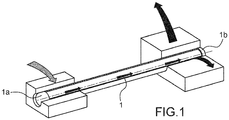
- a heat pipe as shown on figure 1 , comprises in this regard a hermetic enclosure, for example in the form of a hollow tube, which contains a fluid intended to be in a state of liquid-vapor equilibrium.
- one end 1a of heat pipe 1 is in contact with an element to be cooled.
- the fluid in the liquid state at the end 1a vaporizes by absorbing the thermal energy emitted by the element to be cooled, and therefore circulates along the heat pipe to reach another end 1b of said heat pipe at which its thermal energy is dissipated so that said fluid returns to the liquid state.
- a heat sink for example a finned heat sink, is generally arranged at the end 1b.
- the integration of the heat pipe into the element to be cooled is generally carried out by means of an interface, and in particular a plate, intended to ensure thermal contact between the heat pipe and said element.
- a section, called a hot section, of the heat pipe which extends from the end 1a, is inserted into an orifice machined in the interface.
- the thermal contact between the element to be cooled and the heat pipe, mediated by the plate, is not optimum and correspondingly degrades the cooling efficiency of the element to be cooled.
- An aim of the present invention is therefore to provide a method of integrating a heat pipe with a non-planar electrical contact element.
- Another object of the present invention is to provide a method of integrating a heat pipe as close as possible to a hot point of electrical equipment.
- Another aim of the present invention is to provide a method making it possible to optimize the thermal contact between a heat pipe and an element to be cooled.
- the objects of the invention are, at least in part, achieved by a method of integrating a heat pipe with a plate according to the terms of claim 1.
- step c) is carried out so that during folding the two lateral edges of the groove deform and crimp the first section.
- the folding step c) is performed by means of a punch exerting a force at the first section, advantageously, the end of the punch in contact with the first section during the execution of step c) has a shape conforming to said first section.
- the metal plate is placed on a guide having a V-shaped section and the opening of which defines the bending angle of said plate.
- the bending angle ⁇ is between 45 ° and 135 °.
- the groove has a width of between 1.25 and 2.5 times the diameter D.
- the groove has a depth of between 0.3 and 0.9 times the diameter D.
- the groove has a radius of curvature of between 0.25 and 2 times the radius R of the tube.
- the thickness of the metal plate is less than the diameter D.
- the groove is formed according to at least one of the techniques among: machining, drilling, water jet cutting, laser cutting, chemical engraving.
- the metal plate and the groove are formed by additive manufacturing.
- the tube before the folding step, has a filling configured to prevent any deformation of the tube during the folding step b).
- the filling comprises a gas.
- the filling comprises a powder, in particular sand.
- a fluid intended to ensure the transport of heat in the tube of the heat pipe is injected into said tube after bending step c).
- the tube is filled with a fluid intended to ensure the transport of heat in the heat pipe tube is injected into said tube before step b).
- the tube comprises an insert in its internal volume intended to apply a force against the internal surface of the tube and to limit any deformation of the tube during the execution of step c).
- the insert comprises an axis which extends in the direction of extension of the tube, and from which extend fins which exert a force against the internal wall of the tube.
- the fins are in flexion.
- the insert comprises a metal.
- a heat dissipation device in particular a finned heat sink, is arranged at a second end, opposite the first end, of the tube.
- the plate is integrated into an electrical device, at the end of step c), in order to ensure an electrical connection.
- the present invention relates to a method of integrating a heat pipe and a plate intended to form an electrical contact within an electrical device.
- the heat pipe is directly in the volume of the plate to be cooled. It is in particular integrated into the plate via a groove. Folding makes it possible in particular to grip the heat pipe in the groove.
- the method according to the present invention does not require any recourse to an intermediate plate, and makes it possible to integrate the heat pipe as close as possible to the hot source (s) of the device.
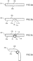
- the figures 2a to 2d and 3a to 3d illustrate the method of integrating a heat pipe 10 with a plate 20 intended to form an electrical contact within one or more electrical devices.
- the plate 20 comprises a metallic species, and is in particular a thermal conductor.
- the plate 20 can in particular comprise copper or aluminum.
- the invention should not be limited to these two materials alone, and those skilled in the art may consider any other metal which may be suitable depending on the intended application.
- the plate 20 is flat and comprises two faces, called main faces 20a and 20b, parallel to each other and connected by a contour 20c ( figures 2a and 3a ).
- the plate 20 has a thickness E defined by the distance between the two main faces 20a and 20b.
- the method according to the present invention comprises a step a) of forming a groove 30 on the main face 20a ( figures 2b and 3b ).
- groove is meant a recessed, narrow and elongated part.
- the groove according to the present invention comprises two edges 31a and 31b which extend in the direction of elongation of said groove.
- the groove is also delimited by a surface, called the contact surface 31c, between the two edges 31a and 31b.
- Groove 30 may be formed by a material subtraction technique.
- step b) can be performed according to one of the methods chosen from: machining, drilling, water jet cutting, laser cutting, chemical etching.
- the plate 20 provided with the groove 30 can be formed by an additive manufacturing technique.
- the method according to the present invention also comprises a step b) of positioning, in the groove 30, a first section 11a of a heat pipe 11 tube 10 ( figure 2c and 3c ).
- the first section 11a extends in particular from one end of the tube 11, called the first end 12a.
- the first section 11a is further delimited by a section of the outer surface of the tube 11, called the first surface 11b.
- the tube may comprise, before execution of step b), a fluid intended to ensure the exchange and transport of heat.
- the tube does not include the fluid intended to ensure the exchanges and transport of heat.
- the tube can include a filling configured to prevent any deformation of the tube during a bending step c) explained below and shown in figures 2d and 3d .
- Step c) of folding the plate 20 is carried out so as to close the groove 30 and thus clamp the first section 11a in said groove 30.
- step c) of folding the plate 20 can be performed so that the contact surface 31c delimiting the groove 30 is fully in contact with the first surface 11b delimiting the first section 11a.
- This aspect thus makes it possible to optimize heat exchanges likely to occur between the plate 20 and the tube 11.
- step c) can be carried out so that the edges 31a and 31b of the groove deform and crimp the first section 11a.
- the crimping comprises a deformation of the edges 31a and 31b of the groove 30 so that the latter conform to the profile of the tube 11.
- the figure 4 illustrates the effect of the crimping of the tube 11 by the edges 31a and 31b of the groove at the level of the zone A. More particularly, during the crimping, the edges 31a and 31b can operate a junction and thus close the groove 30 on the tube 11.
- the bending step c) can be carried out by exerting a force on the tube 11 (for example at the level of the first section 11a) by means of a punch 100 ( figures 5a and 5b ).
- the plate 20 rests on a support 110 which has a V-shaped transverse profile and whose opening defines the bending angle of the plate 20 at the end of step c).
- step c the punch 100 is brought into contact with the tube 11, in particular with the first section 11a, and a pushing force is then applied to said punch 100 so that the latter forces the bending. of the plate.
- the thrust ceases when the plate is folded in accordance with the support 110.
- the end 101 of the punch 100 in contact with the tube 11 can advantageously have a shape conforming to the external surface of the tube 11.
- the contact surface between the punch 100 and the first section 11a can be adjusted so as to allow the deformation of the edges 31a and 31b of the groove 30, and more particularly to allow a rise (the crimping) of said edges 31a and 31b by deformation on the external surface of the first section (zones "B" and "C” figure 5b ).
- the bending angle ⁇ can be between 45 ° and 135 °, and for example equal to 90 °.
- This bending angle can in particular be imposed by the V-shaped opening angle of the support 110 illustrated in figures 5a and 5b .
- the thickness of the plate 20 is advantageously less than the diameter D.
- step c the quality of the contact between the first section and the groove at the end of step c) could depend on the geometric characteristics of the groove.
- the adjustment of the latter according to the diameter D of the tube 11 considered advantageously makes it possible to optimize the thermal contact between said tube 11 and the plate 20.
- the groove 30 advantageously has a width of between 1.25 and 2.5 times the diameter D of the tube 11.
- the groove 30 has a depth of between 0.3 and 0.9 times the diameter D of the tube 11.
- the groove has a radius of curvature from one and the other of the edges 31a and 31b between 0, 25 and 2 times the radius R of the tube.
- radius of curvature from an edge is meant the radius of curvature of a section of the transverse profile of the groove and which extends from said edge.
- a fluid intended to ensure the transport of heat is present in the internal volume of the tube 11 forming the heat pipe 10.
- the tube 11 may include a filling configured to prevent any deformation of the tube during a bending step c).
- This filling can in particular comprise a powder, for example sand, or even a shaft with an external diameter slightly less than the internal diameter of the tube (by less is meant between 5% to 15% less than the internal diameter of the tube).
- Step c) is then followed by a step of removing the filling and possibly cleaning the inside of the tube 11.
- the fluid intended to ensure the transport of heat in the tube 11 of the heat pipe 10 can be injected into said tube.
- the tube 11 may include an insert 40 introduced into its internal volume before or after the execution of step c) of folding.
- the insert 40 is intended in particular to apply a force against the internal surface of the tube and to limit any deformation of the tube during the execution of step c).
- the insert 40 helps to maintain the internal surface of the tube 11 so as to avoid the deformation of the latter during the execution of step c).
- the insert 40 as shown in figures 6 and 7 , comprises an axis 41 which extends in the direction of extension of the tube 11, and from which extend curved fins 42 which exert a force against the internal wall of the tube.
- the fins 42 are flexed.
- the fins can advantageously be arranged in rows which extend along the shaft, and regularly spaced along each row.
- the insert can include three rows of fins.
- the insert may comprise a metal, for example copper, and thus participate in the transport of heat and consequently improve the performance of the heat pipe.
- the implementation of the insert makes it possible in particular to improve the thermal resistance to the evaporator (its conductance will be better), and also to increase the boiling limit of the device (dryout of the wall and interruption of the transmission of heat flow between the hot source and the heat transfer fluid of the heat pipe).
- the method according to the present invention can also comprise the installation of a heat dissipation device 50, in particular a finned heatsink, at a second end, opposite the first end, of the tube.
- a heat dissipation device 50 in particular a finned heatsink
- the figure 8 is a photograph of a heat pipe tube integrated into a plate according to the terms of the present invention.
- the method can include the integration of the folded plate and provided with the heat pipe in an electrical device in order to ensure an electrical connection.
- the present invention thus makes it possible to integrate a heat pipe as close as possible to an element to be cooled of an electrical appliance despite the space constraints and / or the non-flatness of said source likely to appear.
- the method according to the present invention makes it possible to optimize the thermal contact between the heat pipe and the element to be cooled.
- the invention also relates to a heat pipe provided with an insert 40 described above.
Landscapes
- Engineering & Computer Science (AREA)
- Physics & Mathematics (AREA)
- Thermal Sciences (AREA)
- Mechanical Engineering (AREA)
- General Engineering & Computer Science (AREA)
- Microelectronics & Electronic Packaging (AREA)
- Life Sciences & Earth Sciences (AREA)
- Sustainable Development (AREA)
- Cooling Or The Like Of Electrical Apparatus (AREA)
Abstract
a) une étape de formation d'une gorge sur une face principale d'une plaque (20) métallique ;
b) une étape de positionnement d'une première section d'un tube (11) de caloduc (10), de diamètre D, dans la gorge, la première section s'étendant à partir d'une première extrémité dudit tube ;
c) une étape de pliage de la plaque (20) de manière à refermer la gorge et ainsi enserrer la première section dans ladite gorge.
Description
- La présente invention se rapporte au domaine de la gestion thermique, et notamment des transferts thermiques, pour le refroidissement d'appareils électriques.
- En particulier, la présente invention se rapporte à la gestion thermique dans une section confinée d'un appareil électrique. La présente invention met donc en œuvre un caloduc intégré directement à une pièce ou plaque métallique formant un contact et/ou une liaison électrique. La pièce ou la plaque est notamment non plane.
- Les caloducs, bien connus de l'homme du métier, sont des systèmes thermiques mis en œuvre pour le refroidissement de dispositifs.
- Un caloduc, tel qu'illustré à la
figure 1 , comprend à cet égard une enceinte hermétique, par exemple sous forme de tube creux, qui renferme un fluide destiné à être dans un état d'équilibre liquide-vapeur. - En fonctionnement, une extrémité la du caloduc 1 est en contact avec un élément à refroidir.
- Le fluide à l'état liquide au niveau de l'extrémité la se vaporise en absorbant l'énergie thermique émise par l'élément à refroidir, et circule donc le long du caloduc pour atteindre une autre extrémité 1b dudit caloduc au niveau de laquelle son énergie thermique est dissipée de sorte que ledit fluide retourne à l'état liquide.
- Un dissipateur thermique, par exemple un dissipateur à ailettes, est généralement agencé au niveau de l'extrémité 1b.
- L'intégration du caloduc à l'élément à refroidir s'effectue généralement au moyen d'une interface, et notamment d'une platine, destinée à assurer un contact thermique entre le caloduc et ledit élément.
- En particulier, une section, dite section chaude, du caloduc qui s'étend à partir de l'extrémité la, est insérée dans un orifice usiné dans l'interface.
- Le maintien mécanique du caloduc dans la platine peut être obtenu de diverses manières parmi lesquelles on peut citer :
- un montage en force ;
- un montage par écrasement ;
- un montage par application d'une pression interne dans le caloduc permettant de plaquer les parois de la section chaude contre celles de l'orifice ménagé dans l'interface ;
- un montage par olivage ;
- un montage par brasage ;
- un montage par collage.
- Toutefois ces techniques ne sont pas satisfaisantes.
- En effet, le contact thermique entre l'élément à refroidir et le caloduc, médié par la platine, n'est pas optimum et dégrade d'autant l'efficacité du refroidissement de l'élément à refroidir.
- L'optimisation de ce contact thermique reste par ailleurs compliquée à mettre œuvre à un coût acceptable.
- En outre, dès lors qu'il existe une contrainte d'espace et/ou que la zone à refroidir n'est pas plane, l'emploi d'un caloduc intégré à une platine reste compliqué, voire impossible à mettre en œuvre.
- Une telle contrainte existe notamment dès lors que l'élément à refroidir est un appareil électrique, et plus particulièrement lorsqu'il s'agit de refroidir ce dernier au niveau de bornes électriques ou d'éléments de connexion électriques.
- Ces éléments représentent généralement des points chauds au niveau desquels la gestion thermique présente un réel problème.
- Les documents
US 5 826 645 ,US 2016/282054 etUS 2011/162206 divulguent chacun un procédé d'intégration d'un caloduc. Toutefois, les procédés divulgués dans ces documents, dans la mesure où ils ne permettent pas de répondre favorablement aux problématiques décrites ci-avant, ne sont pas non satisfaisants. - Un but de la présente invention est donc de proposer un procédé d'intégration d'un caloduc avec un élément de contact électrique non plan.
- Un autre but de la présente invention est de proposer un procédé d'intégration d'un caloduc au plus près d'un point chaud d'un équipement électrique.
- Un autre but de la présente invention est de proposer un procédé permettant d'optimiser le contact thermique entre un caloduc et un élément à refroidir.
- Les buts de l'invention sont, au moins en partie, atteints par un procédé d'intégration d'un caloduc à une plaque selon les termes de la revendication 1.
- En particulier, les buts de l'invention sont, au moins en partie, atteints par un procédé d'intégration d'un caloduc à une plaque destinée à former un contact électrique au sein d'un ou plusieurs appareils électriques, le procédé comprenant :
- a) une étape de formation d'une gorge, délimitée par une surface de contact, sur une face principale d'une plaque métallique ;
- b) une étape de positionnement d'une première section d'un tube de caloduc, de diamètre D, dans la gorge, la première section s'étendant à partir d'une première extrémité dudit tube et est délimitée par une première surface ;
- c) une étape de pliage de la plaque de manière à refermer la gorge et ainsi enserrer la première section dans ladite gorge, le pliage étant en outre exécuté de sorte que la surface de contact soit intégralement en contact avec la première surface.
- Selon un mode de mise en œuvre, l'étape c) est exécutée de sorte que lors du pliage les deux bords latéraux de la gorge se déforment et viennent sertir la première section.
- Selon un mode de mise en œuvre, l'étape c) de pliage est exécuté au moyen d'un poinçon exerçant une force au niveau de la première section, avantageusement, l'extrémité du poinçon en contact avec la première section lors de l'exécution de l'étape c) présente une forme conforme à ladite première section.
- Selon un mode de mise en œuvre, lors de l'exécution de l'étape c), la plaque métallique est posée sur un guide présentant une section en V et dont l'ouverture définie l'angle de pliage de ladite plaque.
- Selon un mode de mise en œuvre, l'angle θ de pliage est compris entre 45° et 135°.
- Selon un mode de mise en œuvre, la gorge présente une largeur comprise entre 1,25 et 2,5 fois le diamètre D.
- Selon un mode de mise en œuvre, la gorge présente une profondeur comprise entre 0,3 et 0,9 fois le diamètre D.
- Selon un mode de mise en œuvre, la gorge présente un rayon de courbure compris entre 0,25 et 2 fois le rayon R du tube.
- Selon un mode de mise en œuvre, l'épaisseur de la plaque métallique est inférieure au diamètre D.
- Selon un mode de mise en œuvre, la gorge est formée selon au moins une des techniques parmi : usinage, perçage, découpe au jet d'eau, découpe laser, gravure chimique.
- Selon un mode de mise en œuvre, la plaque métallique ainsi que la gorge sont formées par fabrication additive.
- Selon un mode de mise en œuvre, avant l'étape de pliage, le tube présente un remplissage configuré pour prévenir toute déformation du tube lors de l'étape b) de pliage.
- Selon un mode de mise en œuvre, le remplissage comprend un gaz.
- Selon un mode de mise en œuvre, le remplissage comprend une poudre, notamment du sable.
- Selon un mode de mise en œuvre, un fluide destiné à assurer le transport de chaleur dans le tube du caloduc est injecté dans ledit tube après l'étape c) de pliage.
- Selon un mode de mise en œuvre, le tube est rempli d'un fluide destiné à assurer le transport de chaleur dans le tube du caloduc est injecté dans ledit tube avant l'étape b).
- Selon un mode de mise en œuvre, le tube comprend un insert dans son volume interne destiné à appliquer une force contre la surface interne du tube et limiter toute déformation du tube lors de l'exécution de l'étape c).
- Selon un mode de mise en œuvre, l'insert comprend un axe qui s'étend selon la direction d'extension du tube, et à partir duquel s'étendent des ailettes qui exercent une force contre la paroi interne du tube.
- Selon un mode de mise en œuvre, les ailettes sont en flexion.
- Selon un mode de mise en œuvre, l'insert comprend un métal.
- Selon un mode de mise en œuvre, un dispositif de dissipation de chaleur, notamment un dissipateur à ailettes, est disposé au niveau d'une seconde extrémité, opposée à la première extrémité, du tube.
- Selon un mode de mise en œuvre, plaque est intégrée à un appareil électrique, à l'issue de l'étape c), afin d'assurer une connexion électrique.
- D'autres caractéristiques et avantages apparaîtront dans la description qui va suivre d'un procédé d'intégration d'un caloduc à une plaque selon l'invention, donnés à titre d'exemples non limitatifs, en référence aux dessins annexés dans lesquels :
- La
figure 1 est une illustration d'un caloduc et de son fonctionnement ; - Les
figures 2a, 2b, 2c, 2d sont des illustrations, en perspective, des différentes étapes mises en œuvre dans le cadre de la présente invention ; - Les
figures 3a, 3b, 3c, 3d sont des illustrations, selon un plan de coupe transversal à la gorge, des différentes étapes mises en œuvre dans le cadre de la présente invention ; - La
figure 4 est une représentation schématique du sertissage du tube du caloduc par les bords de la gorge ; - Les
figures 5a, 5b illustrent de manière schématique un exemple de mise en œuvre de l'étape c), respectivement avant et après pliage, mettant notamment en œuvre un poinçon et un guide de pliage sur lequel repose la plaque par une face opposée à la face sur laquelle la gorge est formée ; - La
figure 6 est une représentation schématique selon une vue en perspective d'un insert susceptible d'être mis en œuvre dans la cadre de la présente invention ; - La
figure 7 est une représentation schématique selon un plan de coupe transversal du tube dans lequel est inséré l'insert avec des ailettes en flexion, les flèches indiquant les directions de poussée des différentes ailettes ; - La
figure 8 est une photographie d'un tube de caloduc intégré à une plaque selon les termes de la présente invention. - La présente invention concerne un procédé d'intégration d'un caloduc et d'une plaque destinée à former un contact électrique au sein d'un appareil électrique.
- Le caloduc est directement dans le volume de plaque à refroidir. Il est notamment intégré à la plaque via une gorge. Le pliage permet notamment d'enserrer le caloduc dans la gorge.
- Le procédé selon la présente invention ne nécessite aucun recours à une platine intermédiaire, et permet d'intégrer le caloduc au plus près de la ou des sources chaudes de l'appareil.
- Les
figures 2a à 2d et3a à 3d illustrent le procédé d'intégration d'un caloduc 10 à une plaque 20 destinée à former un contact électrique au sein d'un ou plusieurs appareils électriques. - La plaque 20 comprend une espèce métallique, et est notamment un conducteur thermique. La plaque 20 peut en particulier comprendre du cuivre ou de l'aluminium. Toutefois, l'invention ne doit pas être limitée à ces deux seuls matériaux, et l'homme du métier pourra considérer tout autre métal susceptible de convenir en fonction de l'application visée.
- La plaque 20 est plane et comprend deux faces, dites faces principales 20a et 20b, parallèles entre elles et reliées par un contour 20c (
figures 2a et3a ). - La plaque 20 présente une épaisseur E définie par la distance entre les deux faces principales 20a et 20b.
- Le procédé selon la présente invention comprend une étape a) de formation d'une gorge 30 sur la face principale 20a (
figures 2b et3b ). - Par « gorge », on entend une partie évidée, étroite et allongée. La gorge selon la présente invention comprend deux bords 31a et 31b qui s'étendent selon la direction d'élongation de ladite gorge. La gorge est également délimitée par une surface, dite surface de contact 31c, entre les deux bords 31a et 31b.
- La gorge 30 peut être formée par une technique de soustraction de matière.
- Par exemple, l'étape b) peut être exécutée selon l'une des méthodes choisie parmi : usinage, perçage, découpe au jet d'eau, découpe laser, gravure chimique.
- De manière alternative, la plaque 20 pourvue de la gorge 30 peut être formée par une technique de fabrication additive.
- Le procédé selon la présente invention comprend également une étape b) de positionnement, dans la gorge 30, d'une première section 11a d'un tube 11 de caloduc 10 (
figure 2c et3c ). - La première section 11a s'étend notamment à partir d'une extrémité du tube 11, dite première extrémité 12a. La première section 11a est par ailleurs délimité par une section de la surface externe du tube 11, dite première surface 11b.
- Selon une première variante de la présente invention, le tube peut comprendre, avant exécution de l'étape b), un fluide destiné à assurer les échanges et transport de chaleur.
- Selon une seconde variante de l'invention, le tube ne comprend pas le fluide destiné à assurer les échanges et transport de chaleur. Le tube peut en revanche comprendre un remplissage configuré pour prévenir toute déformation du tube lors d'une étape c) de pliage explicité ci-après et représentée aux
figures 2d et3d . - L'étape c) de pliage de la plaque 20 est exécutée de manière à refermer la gorge 30 et ainsi enserrer la première section 11a dans ladite gorge 30.
- Plus particulièrement, l'étape c) de pliage de la plaque 20 peut être exécuté de sorte que la surface de contact 31c délimitant la gorge 30 soit intégralement en contact avec de la première surface 11b délimitant la première section 11a.
- Cet aspect permet ainsi d'optimiser des échanges thermiques susceptibles d'intervenir entre la plaque 20 et le tube 11.
- En outre, l'étape c) peut être exécutée de sorte que les bords 31a et 31b de la gorge se déforment et viennent sertir la première section 11a. Plus particulièrement, le sertissage comprend une déformation des bords 31a et 31b de la gorge 30 de sorte que ces derniers viennent épouser le profil du tube 11. La
figure 4 illustre l'effet du sertissage du tube 11 par les bords 31a et 31b de la gorge au niveau de la zone A. Plus particulièrement, lors du sertissage, les bords 31a et 31b peuvent opérer une jonction et ainsi refermer la gorge 30 sur le tube 11. - L'étape c) de pliage peut être exécutée en exerçant une force sur le tube 11 (par exemple au niveau de la première section 11a) au moyen d'un poinçon 100 (
figures 5a et 5b ). - Selon cet exemple particulier, la plaque 20 repose sur un support 110 qui présente un profil transversal en forme de V et dont l'ouverture définie l'angle de pliage de la plaque 20 à l'issue de l'étape c).
- Lors de l'exécution de l'étape c), le poinçon 100 est mis en contact avec le tube 11, notamment avec la première section 11a, et une force de poussée est alors appliquée audit poinçon 100 de sorte que ce dernier force le pliage de la plaque. La poussée cesse dès lors que la plaque est pliée de manière conforme au support 110.
- L'extrémité 101 du poinçon 100 en contact avec le tube 11 peut avantageusement présenter une forme conforme à la surface externe du tube 11.
- La surface de contact entre le poinçon 100 et la première section 11a peut être ajustée de manière à permettre la déformation des bords 31a et 31b de la gorge 30, et plus particulièrement autoriser une remontée (le sertissage) desdits bords 31a et 31b par déformation sur la surface externe de la première section (zones « B » et « C »
figure 5b ). - L'angle θ de pliage peut être compris entre 45 ° et 135 °, et par exemple égal à 90°.
- Cet angle de pliage peut notamment être imposé par l'angle d'ouverture en V du support 110 illustré aux
figures 5a et 5b . - L'épaisseur de la plaque 20 est avantageusement inférieure au diamètre D.
- Les inventeurs ont remarqué que la qualité du contact entre la première section et la gorge à l'issue de l'étape c) pouvait dépendre des caractéristiques géométriques de la gorge.
- Plus particulièrement, l'ajustement de ces dernières en fonction du diamètre D du tube 11 considéré permet avantageusement d'optimiser le contact thermique entre ledit tube 11 et la plaque 20.
- Notamment, la gorge 30 présente avantageusement une largeur comprise entre 1,25 et 2,5 fois le diamètre D du tube 11.
- De manière complémentaire ou alternative, la gorge 30 présente une profondeur comprise entre 0,3 et 0,9 fois le diamètre D du tube 11.
- Toujours de manière complémentaire ou alternative à l'une et/ou l'autre des caractéristiques géométriques reprises ci-avant, la gorge présente un rayon de courbure à partir de l'un et l'autre des bords 31a et 31b compris entre 0,25 et 2 fois le rayon R du tube.
- Par « rayon de courbure à partir d'un bord », on entend le rayon de courbure d'une section du profil transversal de la gorge et qui s'étend à partir dudit bord.
- Selon la première variante présentée précédemment, un fluide destinée à assurer le transport de chaleur est présent dans le volume interne du tube 11 formant le caloduc 10.
- Selon la seconde variante présentée précédemment, le tube 11 peut comprendre un remplissage configuré pour prévenir toute déformation du tube lors d'une étape c) de pliage.
- Ce remplissage peut notamment comprendre une poudre, par exemple du sable, ou encore un arbre de diamètre externe légèrement inférieur au diamètre interne du tube (par inférieur, on entend entre 5% à 15% inférieur au diamètre interne du tube).
- L'étape c) est alors suivie d'une étape de retrait du remplissage et éventuellement de nettoyage de l'intérieur du tube 11.
- Le fluide destiné à assurer le transport de chaleur dans le tube 11 du caloduc 10 peut être injecté dans ledit tube.
- Quel que soit la variante considérée, le tube 11 peut comprendre un insert 40 introduit dans son volume interne avant ou après l'exécution de l'étape c) de pliage.
- L'insert 40 est notamment destiné à appliquer une force contre la surface interne du tube et limiter toute déformation du tube lors de l'exécution de l'étape c).
- En d'autres termes, l'insert 40 aide au maintien de la surface interne du tube 11 de manière à éviter la déformation de ce dernier lors de l'exécution de l'étape c).
- L'insert 40, tel que représenté aux
figures 6 et 7 , comprend un axe 41 qui s'étend selon la direction d'extension du tube 11, et à partir duquel s'étendent des ailettes 42 courbées qui exercent une force contre la paroi interne du tube. - En d'autres termes, les ailettes 42 sont en flexion.
- Les ailettes peuvent avantageusement être agencées en rangées qui s'étendent le long de l'arbre, et régulièrement espacées le long de chaque rangée.
- Par exemple, l'insert peut comprendre trois rangées d'ailettes.
- L'insert peut comprendre un métal, par exemple du cuivre, et ainsi participer au transport de chaleur et par voie de conséquence améliorer les performances du caloduc. La mise en œuvre de l'insert permet notamment d'améliorer la résistance thermique à l'évaporateur (sa conductance sera meilleure), et également d'augmenter la limite d'ébullition du dispositif (dryout de la paroi et interruption de la transmission du flux thermique entre la source chaude et le fluide caloporteur du caloduc).
- Le procédé selon la présente invention peut également comprendre l'installation d'un dispositif de dissipation de chaleur 50, notamment un dissipateur à ailettes, au niveau d'une seconde extrémité, opposée à la première extrémité, du tube.
- La
figure 8 est une photographie d'un tube de caloduc intégré à une plaque selon les termes de la présente invention. - Enfin le procédé peut comprendre l'intégration de la plaque pliée et pourvue du caloduc dans un appareil électrique afin d'assurer une connexion électrique.
- La présente invention permet ainsi d'intégrer un caloduc au plus près d'un élément à refroidir d'un appareil électrique malgré les contraintes d'espace et/ou de non planéité de ladite source susceptible d'apparaître.
- Par ailleurs, le procédé selon la présente invention permet d'optimiser le contact thermique entre le caloduc et l'élément à refroidir.
- L'invention concerne également un caloduc pourvu d'un insert 40 décrit ci-avant.
Claims (14)
- Procédé d'intégration d'un caloduc (10) à une plaque (20) destinée à former un contact électrique au sein d'un ou plusieurs appareils électriques, le procédé comprenant :a) une étape de formation d'une gorge (30), délimitée par une surface de contact (31c), sur une face principale (20a) d'une plaque (20) métallique ;b) une étape de positionnement d'une première section (11a) d'un tube (11) de caloduc (10), de diamètre D, dans la gorge (30), la première section (11a) s'étendant à partir d'une première extrémité (12a) dudit tube (11) et est délimitée par une première surface (11b) ;c) une étape de pliage de la plaque (20) de manière à refermer la gorge (30) et ainsi enserrer la première section (11a) dans ladite gorge (30), le pliage étant en outre exécuté de sorte que la surface de contact (31c) soit intégralement en contact avec la première surface (11b), avantageusement, l'étape c) est exécutée de sorte que lors du pliage, les deux bords (31a, 31b) latéraux de la gorge (30) se déforment et viennent sertir la première section (11a).
- Procédé selon la revendication 1, dans lequel l'étape c) de pliage est exécuté au moyen d'un poinçon exerçant une force au niveau de la première section (11a), avantageusement, l'extrémité (101) du poinçon (100) en contact avec la première section (11a) lors de l'exécution de l'étape c) présente une forme conforme à ladite première section (11a), encore plus avantageusement lors de l'exécution de l'étape c), la plaque (20) métallique est posée sur un support (110) présentant une section en V et dont l'ouverture définie l'angle de pliage de ladite plaque (20).
- Procédé selon la revendication 1 ou 2, dans lequel l'angle θ de pliage est compris entre 45 ° et 135 °.
- Procédé selon l'une des revendications 1 à 3, dans lequel la gorge (30) présente une largeur comprise entre 1,25 et 2,5 fois le diamètre D.
- Procédé selon l'une des revendications 1 à 4, dans lequel la gorge (30) présente une profondeur comprise entre 0,3 et 0,9 fois le diamètre D.
- Procédé selon l'une des revendications 1 à 5, dans lequel la gorge (30) présente un rayon de courbure à partir de l'un et l'autre des bords (31a, 31b) de ladite gorge (30) compris entre 0,25 et 2 fois le rayon R du tube (11).
- Procédé selon l'une des revendications 1 à 6, dans lequel l'épaisseur de la plaque (20) métallique est inférieure au diamètre D.
- Procédé selon l'une des revendications 1 à 7, dans lequel la gorge (30) est formée selon au moins une des techniques parmi : usinage, perçage, découpe au jet d'eau, découpe laser, gravure chimique.
- Procédé selon l'une des revendications 1 à 7, dans lequel la plaque (20) métallique ainsi que la gorge (30) sont formées par fabrication additive.
- Procédé selon l'une des revendications 1 à 9, dans lequel, avant l'étape de pliage, le tube (11) présente un remplissage configuré pour prévenir toute déformation du tube (11) lors de l'étape c) de pliage, avantageusement, le remplissage comprend un gaz ou une poudre, et notamment du sable.
- Procédé selon l'une des revendications 1 à 10, dans lequel un fluide destiné à assurer le transport de chaleur dans le tube (11) du caloduc (10) est injecté dans ledit tube (11) après l'étape c) de pliage.
- Procédé selon l'une des revendications 1 à 9, dans lequel le tube (11) est rempli d'un fluide destiné à assurer le transport de chaleur dans le tube (11) du caloduc (10) est injecté dans ledit tube (11) avant l'étape b), avantageusement, le tube (11) comprend un insert (40) dans son volume interne destiné à appliquer une force contre la surface interne du tube (11) et limiter toute déformation du tube (11) lors de l'exécution de l'étape c), plus avantageusement, l'insert (40) comprend un axe (41) qui s'étend selon la direction d'extension du tube (11), et à partir duquel s'étendent des ailettes courbées qui exercent une force contre la paroi interne du tube (11), encore plus avantageusement les ailettes sont en flexion.
- Procédé selon l'une des revendications 1 à 12, dans lequel un dispositif de dissipation de chaleur, notamment un dissipateur à ailettes, est disposé au niveau d'une seconde extrémité, opposée à la première extrémité (12a), du tube (11).
- Procédé selon l'une des revendications 1 à 13, dans lequel la plaque (20) est intégrée à un appareil électrique, à l'issue de l'étape c), afin d'assurer une connexion électrique.
Applications Claiming Priority (2)
| Application Number | Priority Date | Filing Date | Title |
|---|---|---|---|
| FR1904362A FR3095559A1 (fr) | 2019-04-25 | 2019-04-25 | Procédé de commande d’un convertisseur dc/ac |
| FR1907133A FR3098079B1 (fr) | 2019-06-28 | 2019-06-28 | Procédé d’intégration d’un caloduc à une plaque destinée à former un contact électrique |
Publications (2)
| Publication Number | Publication Date |
|---|---|
| EP3731613A1 true EP3731613A1 (fr) | 2020-10-28 |
| EP3731613B1 EP3731613B1 (fr) | 2022-12-21 |
Family
ID=72560276
Family Applications (1)
| Application Number | Title | Priority Date | Filing Date |
|---|---|---|---|
| EP20181973.7A Active EP3731613B1 (fr) | 2019-04-25 | 2020-06-24 | Procédé d'intégration d'un caloduc à une plaque destinée à former un contact électrique |
Country Status (1)
| Country | Link |
|---|---|
| EP (1) | EP3731613B1 (fr) |
Citations (3)
| Publication number | Priority date | Publication date | Assignee | Title |
|---|---|---|---|---|
| US5826645A (en) | 1997-04-23 | 1998-10-27 | Thermal Corp. | Integrated circuit heat sink with rotatable heat pipe |
| US20110162206A1 (en) | 2010-01-07 | 2011-07-07 | Shyh-Ming Chen | Method for connecting heat-dissipating fin and heat pipe |
| US20160282054A1 (en) | 2013-12-24 | 2016-09-29 | Furukawa Electric Co., Ltd. | Heat receiving structure and heat sink |
-
2020
- 2020-06-24 EP EP20181973.7A patent/EP3731613B1/fr active Active
Patent Citations (3)
| Publication number | Priority date | Publication date | Assignee | Title |
|---|---|---|---|---|
| US5826645A (en) | 1997-04-23 | 1998-10-27 | Thermal Corp. | Integrated circuit heat sink with rotatable heat pipe |
| US20110162206A1 (en) | 2010-01-07 | 2011-07-07 | Shyh-Ming Chen | Method for connecting heat-dissipating fin and heat pipe |
| US20160282054A1 (en) | 2013-12-24 | 2016-09-29 | Furukawa Electric Co., Ltd. | Heat receiving structure and heat sink |
Also Published As
| Publication number | Publication date |
|---|---|
| EP3731613B1 (fr) | 2022-12-21 |
Similar Documents
| Publication | Publication Date | Title |
|---|---|---|
| EP2711299B1 (fr) | Structure thermomécanique adaptée pour un environnement spatial | |
| FR2686765A1 (fr) | Dispositif de fixation, notamment pour la fixation d'un composant electronique sur une paroi d'un dissipateur thermique . | |
| WO2007104857A1 (fr) | Echangeur de chaleur et son procede de fabrication | |
| WO2011042491A1 (fr) | Plaque collectrice pour un echangeur de chaleur et echangeur de chaleur correspondant | |
| EP3731613B1 (fr) | Procédé d'intégration d'un caloduc à une plaque destinée à former un contact électrique | |
| EP3532791B1 (fr) | Plaque collectrice pour échangeur de chaleur de véhicule automobile | |
| FR3098079A1 (fr) | Procédé d’intégration d’un caloduc à une plaque destinée à former un contact électrique | |
| EP3167177B1 (fr) | Culasse, element et semelle de moteur a piston | |
| EP1174673A2 (fr) | Module d'échange de chaleur, notamment pour véhicule automobile, et procédé de fabrication de ce module | |
| EP3540359B1 (fr) | Dispositif de conduction thermique et système de dissipation de chaleur associé | |
| WO2024027962A1 (fr) | Echangeur de chaleur | |
| EP3491316B1 (fr) | Plaque collectrice, boite collectrice et echangeur thermique correspondants | |
| EP3140603A1 (fr) | Tube plat pour échangeur de chaleur | |
| WO2019229369A1 (fr) | Boite collectrice et échangeur thermique correspondant | |
| EP3577408B1 (fr) | Collecteur pour échangeur de chaleur | |
| FR2685816A1 (fr) | Systeme de refroidissement pour module "multi-puces". | |
| FR3090841A1 (fr) | Tube pour bloc de chauffage, bloc de chauffage associé et procédé de fabrication dudit bloc | |
| EP3814692B1 (fr) | Bloc de chauffage electrique | |
| EP3182814B1 (fr) | Circuit de refroidissement et dispositif electrique comprenant le circuit de refroidissement | |
| FR3002619B1 (fr) | Appareil de chauffage a fluide caloporteur | |
| EP4482272A1 (fr) | Carte électronique equipée d'un dispositif de dissipation thermique et appareil comprenant une telle carte électronique | |
| WO2017046485A1 (fr) | Module et dispositif thermo électrique, notamment destinés a générer un courant électrique dans un véhicule automobile, et procédé de fabrication d'un tel module | |
| WO2004025204A2 (fr) | Module d'echange de chaleur, en particulier pour les vehicules automobiles | |
| FR2742219A1 (fr) | Evaporateur de boucle fluide a pompage capillaire | |
| EP0792718A1 (fr) | Procédé de fabrication d'un échangeur thermique |
Legal Events
| Date | Code | Title | Description |
|---|---|---|---|
| PUAI | Public reference made under article 153(3) epc to a published international application that has entered the european phase |
Free format text: ORIGINAL CODE: 0009012 |
|
| STAA | Information on the status of an ep patent application or granted ep patent |
Free format text: STATUS: REQUEST FOR EXAMINATION WAS MADE |
|
| 17P | Request for examination filed |
Effective date: 20200624 |
|
| AK | Designated contracting states |
Kind code of ref document: A1 Designated state(s): AL AT BE BG CH CY CZ DE DK EE ES FI FR GB GR HR HU IE IS IT LI LT LU LV MC MK MT NL NO PL PT RO RS SE SI SK SM TR |
|
| AX | Request for extension of the european patent |
Extension state: BA ME |
|
| GRAP | Despatch of communication of intention to grant a patent |
Free format text: ORIGINAL CODE: EPIDOSNIGR1 |
|
| STAA | Information on the status of an ep patent application or granted ep patent |
Free format text: STATUS: GRANT OF PATENT IS INTENDED |
|
| INTG | Intention to grant announced |
Effective date: 20220718 |
|
| GRAS | Grant fee paid |
Free format text: ORIGINAL CODE: EPIDOSNIGR3 |
|
| GRAA | (expected) grant |
Free format text: ORIGINAL CODE: 0009210 |
|
| STAA | Information on the status of an ep patent application or granted ep patent |
Free format text: STATUS: THE PATENT HAS BEEN GRANTED |
|
| AK | Designated contracting states |
Kind code of ref document: B1 Designated state(s): AL AT BE BG CH CY CZ DE DK EE ES FI FR GB GR HR HU IE IS IT LI LT LU LV MC MK MT NL NO PL PT RO RS SE SI SK SM TR |
|
| REG | Reference to a national code |
Ref country code: GB Ref legal event code: FG4D Free format text: NOT ENGLISH |
|
| REG | Reference to a national code |
Ref country code: DE Ref legal event code: R096 Ref document number: 602020007024 Country of ref document: DE |
|
| REG | Reference to a national code |
Ref country code: CH Ref legal event code: EP |
|
| REG | Reference to a national code |
Ref country code: AT Ref legal event code: REF Ref document number: 1539845 Country of ref document: AT Kind code of ref document: T Effective date: 20230115 |
|
| REG | Reference to a national code |
Ref country code: IE Ref legal event code: FG4D Free format text: LANGUAGE OF EP DOCUMENT: FRENCH |
|
| REG | Reference to a national code |
Ref country code: SE Ref legal event code: TRGR |
|
| REG | Reference to a national code |
Ref country code: LT Ref legal event code: MG9D |
|
| REG | Reference to a national code |
Ref country code: NL Ref legal event code: MP Effective date: 20221221 |
|
| PG25 | Lapsed in a contracting state [announced via postgrant information from national office to epo] |
Ref country code: NO Free format text: LAPSE BECAUSE OF FAILURE TO SUBMIT A TRANSLATION OF THE DESCRIPTION OR TO PAY THE FEE WITHIN THE PRESCRIBED TIME-LIMIT Effective date: 20230321 Ref country code: LT Free format text: LAPSE BECAUSE OF FAILURE TO SUBMIT A TRANSLATION OF THE DESCRIPTION OR TO PAY THE FEE WITHIN THE PRESCRIBED TIME-LIMIT Effective date: 20221221 Ref country code: FI Free format text: LAPSE BECAUSE OF FAILURE TO SUBMIT A TRANSLATION OF THE DESCRIPTION OR TO PAY THE FEE WITHIN THE PRESCRIBED TIME-LIMIT Effective date: 20221221 |
|
| REG | Reference to a national code |
Ref country code: AT Ref legal event code: MK05 Ref document number: 1539845 Country of ref document: AT Kind code of ref document: T Effective date: 20221221 |
|
| PG25 | Lapsed in a contracting state [announced via postgrant information from national office to epo] |
Ref country code: RS Free format text: LAPSE BECAUSE OF FAILURE TO SUBMIT A TRANSLATION OF THE DESCRIPTION OR TO PAY THE FEE WITHIN THE PRESCRIBED TIME-LIMIT Effective date: 20221221 Ref country code: LV Free format text: LAPSE BECAUSE OF FAILURE TO SUBMIT A TRANSLATION OF THE DESCRIPTION OR TO PAY THE FEE WITHIN THE PRESCRIBED TIME-LIMIT Effective date: 20221221 Ref country code: HR Free format text: LAPSE BECAUSE OF FAILURE TO SUBMIT A TRANSLATION OF THE DESCRIPTION OR TO PAY THE FEE WITHIN THE PRESCRIBED TIME-LIMIT Effective date: 20221221 Ref country code: GR Free format text: LAPSE BECAUSE OF FAILURE TO SUBMIT A TRANSLATION OF THE DESCRIPTION OR TO PAY THE FEE WITHIN THE PRESCRIBED TIME-LIMIT Effective date: 20230322 |
|
| PG25 | Lapsed in a contracting state [announced via postgrant information from national office to epo] |
Ref country code: NL Free format text: LAPSE BECAUSE OF FAILURE TO SUBMIT A TRANSLATION OF THE DESCRIPTION OR TO PAY THE FEE WITHIN THE PRESCRIBED TIME-LIMIT Effective date: 20221221 |
|
| PG25 | Lapsed in a contracting state [announced via postgrant information from national office to epo] |
Ref country code: SM Free format text: LAPSE BECAUSE OF FAILURE TO SUBMIT A TRANSLATION OF THE DESCRIPTION OR TO PAY THE FEE WITHIN THE PRESCRIBED TIME-LIMIT Effective date: 20221221 Ref country code: RO Free format text: LAPSE BECAUSE OF FAILURE TO SUBMIT A TRANSLATION OF THE DESCRIPTION OR TO PAY THE FEE WITHIN THE PRESCRIBED TIME-LIMIT Effective date: 20221221 Ref country code: PT Free format text: LAPSE BECAUSE OF FAILURE TO SUBMIT A TRANSLATION OF THE DESCRIPTION OR TO PAY THE FEE WITHIN THE PRESCRIBED TIME-LIMIT Effective date: 20230421 Ref country code: ES Free format text: LAPSE BECAUSE OF FAILURE TO SUBMIT A TRANSLATION OF THE DESCRIPTION OR TO PAY THE FEE WITHIN THE PRESCRIBED TIME-LIMIT Effective date: 20221221 Ref country code: EE Free format text: LAPSE BECAUSE OF FAILURE TO SUBMIT A TRANSLATION OF THE DESCRIPTION OR TO PAY THE FEE WITHIN THE PRESCRIBED TIME-LIMIT Effective date: 20221221 Ref country code: CZ Free format text: LAPSE BECAUSE OF FAILURE TO SUBMIT A TRANSLATION OF THE DESCRIPTION OR TO PAY THE FEE WITHIN THE PRESCRIBED TIME-LIMIT Effective date: 20221221 Ref country code: AT Free format text: LAPSE BECAUSE OF FAILURE TO SUBMIT A TRANSLATION OF THE DESCRIPTION OR TO PAY THE FEE WITHIN THE PRESCRIBED TIME-LIMIT Effective date: 20221221 |
|
| PG25 | Lapsed in a contracting state [announced via postgrant information from national office to epo] |
Ref country code: SK Free format text: LAPSE BECAUSE OF FAILURE TO SUBMIT A TRANSLATION OF THE DESCRIPTION OR TO PAY THE FEE WITHIN THE PRESCRIBED TIME-LIMIT Effective date: 20221221 Ref country code: PL Free format text: LAPSE BECAUSE OF FAILURE TO SUBMIT A TRANSLATION OF THE DESCRIPTION OR TO PAY THE FEE WITHIN THE PRESCRIBED TIME-LIMIT Effective date: 20221221 Ref country code: IS Free format text: LAPSE BECAUSE OF FAILURE TO SUBMIT A TRANSLATION OF THE DESCRIPTION OR TO PAY THE FEE WITHIN THE PRESCRIBED TIME-LIMIT Effective date: 20230421 Ref country code: AL Free format text: LAPSE BECAUSE OF FAILURE TO SUBMIT A TRANSLATION OF THE DESCRIPTION OR TO PAY THE FEE WITHIN THE PRESCRIBED TIME-LIMIT Effective date: 20221221 |
|
| REG | Reference to a national code |
Ref country code: DE Ref legal event code: R097 Ref document number: 602020007024 Country of ref document: DE |
|
| PLBE | No opposition filed within time limit |
Free format text: ORIGINAL CODE: 0009261 |
|
| STAA | Information on the status of an ep patent application or granted ep patent |
Free format text: STATUS: NO OPPOSITION FILED WITHIN TIME LIMIT |
|
| PG25 | Lapsed in a contracting state [announced via postgrant information from national office to epo] |
Ref country code: DK Free format text: LAPSE BECAUSE OF FAILURE TO SUBMIT A TRANSLATION OF THE DESCRIPTION OR TO PAY THE FEE WITHIN THE PRESCRIBED TIME-LIMIT Effective date: 20221221 |
|
| 26N | No opposition filed |
Effective date: 20230922 |
|
| PG25 | Lapsed in a contracting state [announced via postgrant information from national office to epo] |
Ref country code: MC Free format text: LAPSE BECAUSE OF FAILURE TO SUBMIT A TRANSLATION OF THE DESCRIPTION OR TO PAY THE FEE WITHIN THE PRESCRIBED TIME-LIMIT Effective date: 20221221 |
|
| PG25 | Lapsed in a contracting state [announced via postgrant information from national office to epo] |
Ref country code: SI Free format text: LAPSE BECAUSE OF FAILURE TO SUBMIT A TRANSLATION OF THE DESCRIPTION OR TO PAY THE FEE WITHIN THE PRESCRIBED TIME-LIMIT Effective date: 20221221 Ref country code: MC Free format text: LAPSE BECAUSE OF FAILURE TO SUBMIT A TRANSLATION OF THE DESCRIPTION OR TO PAY THE FEE WITHIN THE PRESCRIBED TIME-LIMIT Effective date: 20221221 |
|
| REG | Reference to a national code |
Ref country code: CH Ref legal event code: PL |
|
| REG | Reference to a national code |
Ref country code: BE Ref legal event code: MM Effective date: 20230630 |
|
| PG25 | Lapsed in a contracting state [announced via postgrant information from national office to epo] |
Ref country code: LU Free format text: LAPSE BECAUSE OF NON-PAYMENT OF DUE FEES Effective date: 20230624 |
|
| REG | Reference to a national code |
Ref country code: IE Ref legal event code: MM4A |
|
| PG25 | Lapsed in a contracting state [announced via postgrant information from national office to epo] |
Ref country code: LU Free format text: LAPSE BECAUSE OF NON-PAYMENT OF DUE FEES Effective date: 20230624 |
|
| PG25 | Lapsed in a contracting state [announced via postgrant information from national office to epo] |
Ref country code: IE Free format text: LAPSE BECAUSE OF NON-PAYMENT OF DUE FEES Effective date: 20230624 |
|
| PG25 | Lapsed in a contracting state [announced via postgrant information from national office to epo] |
Ref country code: IE Free format text: LAPSE BECAUSE OF NON-PAYMENT OF DUE FEES Effective date: 20230624 Ref country code: CH Free format text: LAPSE BECAUSE OF NON-PAYMENT OF DUE FEES Effective date: 20230630 |
|
| PG25 | Lapsed in a contracting state [announced via postgrant information from national office to epo] |
Ref country code: IT Free format text: LAPSE BECAUSE OF FAILURE TO SUBMIT A TRANSLATION OF THE DESCRIPTION OR TO PAY THE FEE WITHIN THE PRESCRIBED TIME-LIMIT Effective date: 20221221 Ref country code: BE Free format text: LAPSE BECAUSE OF NON-PAYMENT OF DUE FEES Effective date: 20230630 |
|
| PG25 | Lapsed in a contracting state [announced via postgrant information from national office to epo] |
Ref country code: BG Free format text: LAPSE BECAUSE OF FAILURE TO SUBMIT A TRANSLATION OF THE DESCRIPTION OR TO PAY THE FEE WITHIN THE PRESCRIBED TIME-LIMIT Effective date: 20221221 |
|
| PG25 | Lapsed in a contracting state [announced via postgrant information from national office to epo] |
Ref country code: BG Free format text: LAPSE BECAUSE OF FAILURE TO SUBMIT A TRANSLATION OF THE DESCRIPTION OR TO PAY THE FEE WITHIN THE PRESCRIBED TIME-LIMIT Effective date: 20221221 |
|
| PGFP | Annual fee paid to national office [announced via postgrant information from national office to epo] |
Ref country code: DE Payment date: 20250618 Year of fee payment: 6 |
|
| PGFP | Annual fee paid to national office [announced via postgrant information from national office to epo] |
Ref country code: GB Payment date: 20250625 Year of fee payment: 6 |
|
| PGFP | Annual fee paid to national office [announced via postgrant information from national office to epo] |
Ref country code: FR Payment date: 20250623 Year of fee payment: 6 |
|
| PG25 | Lapsed in a contracting state [announced via postgrant information from national office to epo] |
Ref country code: CY Free format text: LAPSE BECAUSE OF FAILURE TO SUBMIT A TRANSLATION OF THE DESCRIPTION OR TO PAY THE FEE WITHIN THE PRESCRIBED TIME-LIMIT; INVALID AB INITIO Effective date: 20200624 |
|
| PGFP | Annual fee paid to national office [announced via postgrant information from national office to epo] |
Ref country code: SE Payment date: 20250618 Year of fee payment: 6 |
|
| PG25 | Lapsed in a contracting state [announced via postgrant information from national office to epo] |
Ref country code: HU Free format text: LAPSE BECAUSE OF FAILURE TO SUBMIT A TRANSLATION OF THE DESCRIPTION OR TO PAY THE FEE WITHIN THE PRESCRIBED TIME-LIMIT; INVALID AB INITIO Effective date: 20200624 |
|
| PG25 | Lapsed in a contracting state [announced via postgrant information from national office to epo] |
Ref country code: TR Free format text: LAPSE BECAUSE OF FAILURE TO SUBMIT A TRANSLATION OF THE DESCRIPTION OR TO PAY THE FEE WITHIN THE PRESCRIBED TIME-LIMIT Effective date: 20221221 |