EP3731484B1 - Procédé et dispositif de transmission de données - Google Patents
Procédé et dispositif de transmission de données Download PDFInfo
- Publication number
- EP3731484B1 EP3731484B1 EP19738167.6A EP19738167A EP3731484B1 EP 3731484 B1 EP3731484 B1 EP 3731484B1 EP 19738167 A EP19738167 A EP 19738167A EP 3731484 B1 EP3731484 B1 EP 3731484B1
- Authority
- EP
- European Patent Office
- Prior art keywords
- data
- message
- terminal
- communications device
- base station
- Prior art date
- Legal status (The legal status is an assumption and is not a legal conclusion. Google has not performed a legal analysis and makes no representation as to the accuracy of the status listed.)
- Active
Links
- 230000005540 biological transmission Effects 0.000 title claims description 213
- 238000000034 method Methods 0.000 title claims description 159
- 238000004891 communication Methods 0.000 claims description 269
- 238000012545 processing Methods 0.000 claims description 54
- 230000006835 compression Effects 0.000 claims description 53
- 238000007906 compression Methods 0.000 claims description 53
- 230000005641 tunneling Effects 0.000 claims description 5
- 230000006870 function Effects 0.000 description 69
- 230000008569 process Effects 0.000 description 62
- 230000004044 response Effects 0.000 description 28
- 238000010586 diagram Methods 0.000 description 26
- 238000005516 engineering process Methods 0.000 description 21
- 230000004048 modification Effects 0.000 description 16
- 238000012986 modification Methods 0.000 description 16
- 235000008694 Humulus lupulus Nutrition 0.000 description 12
- 238000007726 management method Methods 0.000 description 12
- 230000011664 signaling Effects 0.000 description 12
- 230000006837 decompression Effects 0.000 description 11
- 230000002093 peripheral effect Effects 0.000 description 10
- 238000004590 computer program Methods 0.000 description 8
- 239000000872 buffer Substances 0.000 description 6
- 230000004913 activation Effects 0.000 description 5
- 230000008859 change Effects 0.000 description 5
- 230000003287 optical effect Effects 0.000 description 5
- 230000003068 static effect Effects 0.000 description 5
- 239000000284 extract Substances 0.000 description 4
- 230000003993 interaction Effects 0.000 description 4
- 238000005259 measurement Methods 0.000 description 4
- 238000010295 mobile communication Methods 0.000 description 4
- 230000001174 ascending effect Effects 0.000 description 3
- 230000008878 coupling Effects 0.000 description 3
- 238000010168 coupling process Methods 0.000 description 3
- 238000005859 coupling reaction Methods 0.000 description 3
- 238000009795 derivation Methods 0.000 description 3
- 230000000977 initiatory effect Effects 0.000 description 3
- 230000033001 locomotion Effects 0.000 description 3
- 230000007774 longterm Effects 0.000 description 3
- 102100034112 Alkyldihydroxyacetonephosphate synthase, peroxisomal Human genes 0.000 description 2
- 101000799143 Homo sapiens Alkyldihydroxyacetonephosphate synthase, peroxisomal Proteins 0.000 description 2
- 230000008901 benefit Effects 0.000 description 2
- 238000013500 data storage Methods 0.000 description 2
- 238000013461 design Methods 0.000 description 2
- 238000001514 detection method Methods 0.000 description 2
- 238000007667 floating Methods 0.000 description 2
- 238000013507 mapping Methods 0.000 description 2
- 230000008520 organization Effects 0.000 description 2
- 230000000737 periodic effect Effects 0.000 description 2
- 238000002360 preparation method Methods 0.000 description 2
- 239000007787 solid Substances 0.000 description 2
- 230000005236 sound signal Effects 0.000 description 2
- 239000002699 waste material Substances 0.000 description 2
- JZEPSDIWGBJOEH-UHFFFAOYSA-N 4-decylbicyclo[2.2.1]hept-2-ene Chemical compound C1CC2C=CC1(CCCCCCCCCC)C2 JZEPSDIWGBJOEH-UHFFFAOYSA-N 0.000 description 1
- 101100150274 Caenorhabditis elegans srb-2 gene Proteins 0.000 description 1
- 101100150275 Caenorhabditis elegans srb-3 gene Proteins 0.000 description 1
- 101000741965 Homo sapiens Inactive tyrosine-protein kinase PRAG1 Proteins 0.000 description 1
- 101100240462 Homo sapiens RASAL2 gene Proteins 0.000 description 1
- 102100038659 Inactive tyrosine-protein kinase PRAG1 Human genes 0.000 description 1
- 102100035410 Ras GTPase-activating protein nGAP Human genes 0.000 description 1
- 230000001133 acceleration Effects 0.000 description 1
- 230000006978 adaptation Effects 0.000 description 1
- 238000003491 array Methods 0.000 description 1
- 230000003190 augmentative effect Effects 0.000 description 1
- 230000009849 deactivation Effects 0.000 description 1
- 238000007599 discharging Methods 0.000 description 1
- 238000000802 evaporation-induced self-assembly Methods 0.000 description 1
- 230000005484 gravity Effects 0.000 description 1
- 239000004973 liquid crystal related substance Substances 0.000 description 1
- 239000000463 material Substances 0.000 description 1
- 239000002184 metal Substances 0.000 description 1
- 239000000203 mixture Substances 0.000 description 1
- 239000013307 optical fiber Substances 0.000 description 1
- 239000004065 semiconductor Substances 0.000 description 1
- 238000010897 surface acoustic wave method Methods 0.000 description 1
- 238000012546 transfer Methods 0.000 description 1
- CSRZQMIRAZTJOY-UHFFFAOYSA-N trimethylsilyl iodide Substances C[Si](C)(C)I CSRZQMIRAZTJOY-UHFFFAOYSA-N 0.000 description 1
- 238000012795 verification Methods 0.000 description 1
- 230000000007 visual effect Effects 0.000 description 1
Images


Classifications
-
- H—ELECTRICITY
- H04—ELECTRIC COMMUNICATION TECHNIQUE
- H04L—TRANSMISSION OF DIGITAL INFORMATION, e.g. TELEGRAPHIC COMMUNICATION
- H04L69/00—Network arrangements, protocols or services independent of the application payload and not provided for in the other groups of this subclass
- H04L69/30—Definitions, standards or architectural aspects of layered protocol stacks
- H04L69/32—Architecture of open systems interconnection [OSI] 7-layer type protocol stacks, e.g. the interfaces between the data link level and the physical level
- H04L69/321—Interlayer communication protocols or service data unit [SDU] definitions; Interfaces between layers
-
- H—ELECTRICITY
- H04—ELECTRIC COMMUNICATION TECHNIQUE
- H04W—WIRELESS COMMUNICATION NETWORKS
- H04W40/00—Communication routing or communication path finding
- H04W40/02—Communication route or path selection, e.g. power-based or shortest path routing
- H04W40/22—Communication route or path selection, e.g. power-based or shortest path routing using selective relaying for reaching a BTS [Base Transceiver Station] or an access point
-
- H—ELECTRICITY
- H04—ELECTRIC COMMUNICATION TECHNIQUE
- H04L—TRANSMISSION OF DIGITAL INFORMATION, e.g. TELEGRAPHIC COMMUNICATION
- H04L69/00—Network arrangements, protocols or services independent of the application payload and not provided for in the other groups of this subclass
- H04L69/06—Notations for structuring of protocol data, e.g. abstract syntax notation one [ASN.1]
-
- H—ELECTRICITY
- H04—ELECTRIC COMMUNICATION TECHNIQUE
- H04L—TRANSMISSION OF DIGITAL INFORMATION, e.g. TELEGRAPHIC COMMUNICATION
- H04L69/00—Network arrangements, protocols or services independent of the application payload and not provided for in the other groups of this subclass
- H04L69/30—Definitions, standards or architectural aspects of layered protocol stacks
- H04L69/32—Architecture of open systems interconnection [OSI] 7-layer type protocol stacks, e.g. the interfaces between the data link level and the physical level
- H04L69/322—Intralayer communication protocols among peer entities or protocol data unit [PDU] definitions
- H04L69/324—Intralayer communication protocols among peer entities or protocol data unit [PDU] definitions in the data link layer [OSI layer 2], e.g. HDLC
-
- H—ELECTRICITY
- H04—ELECTRIC COMMUNICATION TECHNIQUE
- H04L—TRANSMISSION OF DIGITAL INFORMATION, e.g. TELEGRAPHIC COMMUNICATION
- H04L69/00—Network arrangements, protocols or services independent of the application payload and not provided for in the other groups of this subclass
- H04L69/30—Definitions, standards or architectural aspects of layered protocol stacks
- H04L69/32—Architecture of open systems interconnection [OSI] 7-layer type protocol stacks, e.g. the interfaces between the data link level and the physical level
- H04L69/322—Intralayer communication protocols among peer entities or protocol data unit [PDU] definitions
- H04L69/326—Intralayer communication protocols among peer entities or protocol data unit [PDU] definitions in the transport layer [OSI layer 4]
-
- H—ELECTRICITY
- H04—ELECTRIC COMMUNICATION TECHNIQUE
- H04W—WIRELESS COMMUNICATION NETWORKS
- H04W24/00—Supervisory, monitoring or testing arrangements
- H04W24/10—Scheduling measurement reports ; Arrangements for measurement reports
Definitions
- Embodiments of this application relate to the field of communication technologies, and in particular, to a data transmission method and apparatus for a relay system.
- a relay node has features such as wireless self-backhaul and flexible placement.
- a peer packet data convergence protocol Packet Data Convergence Protocol, PDCP
- UE User Equipment
- UE peer Radio link control protocol
- RLC Radio Link Control
- the RN needs to complete processing only at a physical layer (Physical Layer, PHY), a media access control (Media Access Control, MAC) layer, and an RLC layer.
- PHY Physical Layer
- MAC media access control
- RLC Radio Link Control
- a protocol architecture of the RN is referred to as a layer 2 (Layer2, L2) architecture.
- US 20121182929A1 discloses to implement detection on the datatype of the data to be transmitted, a data packet type detection functions needs to be added for the PDCP entity to detect whether the data to be transmitted is the control plane signalling or the user plane data.
- US2015/296414A1 discloses data PUD and control PDU are generated by the transmitter side of the PDCP entity.
- a header compression (HC) feedback packet for informing a header compressor of the situation of a header decompressor; PDCP layer allocates a sequence number to each PDCP SDU; COUNT based on PDCP SN.
- Embodiments of this application provide a data transmission method and apparatus, so that an RN can quickly identify and process data received by the RN.
- a data transmission method applied to a first communications device or a chip in the first communications device wherein the first communications device is an intermediate forwarding node, a serving node of a terminal, a donor base station, or a distributed unit DU in a donor base station system and a peer PDCP layer of the terminal is placed in the donor base station and a peer RLC layer of the terminal is placed in a relay node that is the serving node of the terminal, and the data transmission method comprises: obtaining (S250) first data; and sending (S251) a first message to a second communications device, wherein the first message comprises the first data and a type identifier, the type identifier is used to indicate a type of the first data, and the type of the first data comprises at least one of user plane data, a status report, a control plane message, and a radio resource control, RRC, message of the terminal; and if the first communications device is the intermediate forwarding node, the second communications device is a previous-hop
- a data transmission method applied to a donor base station or a chip in the donor base station wherein a peer PDCP layer of the terminal is placed in the donor base station and a peer RLC layer of a terminal is placed in a relay node that is a serving node of the terminal, and the data transmission method comprises: receiving (S251;S260) a first message sent by a first communications device, wherein the first message comprises first data and a type identifier, the type identifier is used to indicate a type of the first data, and the type of the first data comprises at least one of user plane data, a status report, a control plane message, and a radio resource control, RRC, message of a terminal; determining (S261) the type of the first data based on the type identifier; and processing (S262) the first data based on the type of the first data, wherein if the first data is the user plane data, the first message comprises first indication information and a global sequence number, SN, of
- a data transmission apparatus configured to perform the data transmission method according to the first aspect.
- a data transmission apparatus configured to perform the data transmission method according to the second aspect.
- a donor base station system is a base station system that provides wireless access for a relay node, and is connected to the relay node through a wireless Un interface.
- the donor base station system may be an independent donor base station (e.g. Donor evolved Node Base Station, DeNB), or may include a centralized unit (Centralized Unit, CU) and a distributed unit (Distributed Unit, DU).
- DeNB Donor evolved Node Base Station
- CU Centralized Unit
- DU distributed Unit
- the CU is mainly responsible for centralized radio resource and connection management control, and has a function of a wireless higher-layer protocol stack, such as a radio resource control (Radio Resource Control, RRC) layer and a PDCP layer.
- the CU can also support movement of some core network functions to an access network, which is referred to as an edge computing network, and can meet a higher requirement, on a network latency, of an emerging service (such as a video, online shopping, or virtual/augmented reality) in a future communications network.
- the DU has a distributed user plane processing function, and mainly has a physical layer function and a layer 2 function that has a relatively high real-time requirement.
- the CU has the RRC layer and the PDCP layer, and the DU has an RLC layer, a MAC layer, and a PHY layer.
- the CU may be deployed in a centralized manner, and deployment of the DU depends on an actual network environment. For example, for a core urban area, or an area with relatively high traffic density, a relatively small inter-site distance, or a limited equipment room resource, for example, a college or a large performance venue, the DU may be deployed in a centralized manner. For an area with relatively sparse traffic, a relatively large inter-site distance, or the like, for example, an area such as a suburban county or a mountain area, DUs may be deployed in a distributed manner.
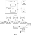
- FIG. 1 is a schematic structural diagram of a base station system including a CU and a DU in a 5th generation communications technology (the 5 Generation Mobile Communication Technology, 5G) system.
- 5G 5th generation communications technology
- the CU communicates with the DU through a CU-DU interface.
- the interface may be configured to transmit a control plane message between the CU and the DU, an RRC message of UE served by the base station system, data of UE served by the base station system, or the like.
- the CU-DU interface is referred to as an F1 interface
- a control plane of the CU-DU interface is referred to as an F1-C
- a user plane of the CU-DU interface is referred to as an F1-U.
- a control plane message, between the CU and the DU, carried on the F1-C is referred to as an F1 application protocol (F1 Application Protocol, F1AP) message.
- F1 application protocol F1 Application Protocol
- the F1AP message may be divided into two parts: a common message (Common Message, or Non UE Associated) and a UE-associated message (UE Associated).
- the common message may be used for management of the F1 interface, an update of a CU/DU configuration, cell management, and the like.
- the UE-associated message may be used to establish/manage/update/delete a UE context, and exchange a quality of service (Quality of Service, QoS) parameter of UE, a protocol stack configuration of the UE, and the like.
- QoS Quality of Service
- the UE-associated message may be further used to transmit an RRC message of the UE.
- a PDCP protocol data unit in an RRC message transmitted over a signaling radio bearer (Signaling Radio Bearers, SRB) 1/SRB 2/ SRB 1S/SRB 2S/SRB 3 of the UE and an RRC PDU in an RRC message transmitted by an SRB 0 are included in the F1AP message for transmission as an RRC container (Container).
- the F1-U transmits data of the UE.
- the PDCP PDU of the UE is encapsulated in a general packet radio service tunneling protocol-user plane (General Packet Radio Service Tunneling Protocol-User Plane, GTP-U) data packet for transmission.
- GTP-U General Packet Radio Service Tunneling Protocol-User Plane
- a DRB of the UE may be identified by using a GTP TEID.
- Un interface A backhaul link of an RN is referred to as a Un interface.
- the Un interface includes a radio transmission interface for communication between the RN and a donor base station system, and a radio transmission interface for communication between RNs.
- Uu interface An access link used by an RN or a donor base station system to serve UE is referred to as a Uu interface.
- a multi-relay network includes a terminal, a plurality of RNs, and a donor base station system. Data or signaling is forwarded by the plurality of RNs from a source (for example, the terminal or the donor base station system) to a sink (for example, the donor base station system or the terminal).
- a source for example, the terminal or the donor base station system
- a sink for example, the donor base station system or the terminal.
- a serving node is a node that is directly connected to a terminal through an air interface in a network and that provides the terminal with control plane message and user plane data transmission.
- An intermediate forwarding node is a node that provides relay transmission for another RN and a node that provides relay transmission for a terminal for which another RN provides a service.
- a level of a quantity of hops may be used to describe a location of an RN in a network.
- a level of a quantity of hops of an RN that directly communicates with a donor base station system is 1, and a level of a quantity of hops of an RN that communicates with the donor base station system by using another RN is 2. The rest can be reduced by analogy.
- a multi-hop relay network includes a donor base station, a relay node 1 to a relay node 4, and a terminal 1 to a terminal 6.
- the donor base station directly communicates with the relay node 1 and the relay node 4.
- An interface between the donor base station and the relay node 1 is a Un1 interface
- an interface between the donor base station and the relay node 4 is a Un4 interface.
- An interface between the relay node 1 and the relay node 2 is a Un2 interface
- an interface between the relay node 2 and the relay node 3 is a Un3 interface.
- the terminal 1 communicates with the relay node 1 through a Uu1 interface
- the terminal 2 communicates with the relay node 2 through a Uu2 interface
- the terminal 3 communicates with the relay node 3 through a Uu3 interface
- the terminal 4 communicates with the relay node 4 through a Uu4 interface
- the terminal 5 communicates with the relay node 1 through a Uu5 interface
- the terminal 6 communicates with the relay node 4 through a Uu6 interface.
- the donor base station directly communicates with the relay node 1 and the relay node 4, levels of quantities of hops of the relay node 1 and the relay node 4 are 1. Because the relay node 2 communicates with the donor base station through the relay node 1, a level of a quantity of hops of the relay node 2 is 2. Similarly, a level of a quantity of hops of the relay node 5 is also 2. Because the relay node 3 communicates with the Donor node through the relay node 2 and the relay node 1, a level of a quantity of hops of the relay node 3 is 3.
- the relay node 1 is an intermediate forwarding node of the relay node 2, the relay node 1 and the relay node 2 are intermediate forwarding nodes of the relay node 3, the relay node 1 and the relay node 2 are intermediate forwarding nodes of the terminal 3 and the terminal 5, and the like.
- the relay node 1 is a serving node of the terminal 1
- the relay node 2 is a serving node of the terminal 2
- the relay node 3 is a serving node of the terminal 3 and the terminal 5
- the relay node 4 is a serving node of the terminal 4 and the terminal 6.
- a previous-hop node of the intermediate forwarding node is the donor base station or the DU in the donor base station system.
- the intermediate forwarding node may be referred to as a next-hop node of the donor base station or the DU in the donor base station system.
- each node has a complete protocol stack.
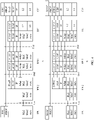
- FIG. 3 shows a protocol stack architecture of each node in a network including an RN.
- the protocol stack architecture includes a control-plane protocol stack architecture and a user-plane protocol stack architecture.
- a in FIG. 3 shows control-plane protocol stacks of UE, an RN, a donor base station, and a mobility management module (Mobility Management Entity, MME) (denoted as MME-UE in the figure) that provides a service for the UE.
- the control-plane protocol stack of the UE includes a non-access stratum (non-Access Stratum, NAS), a radio resource control (Radio Resource Control, RRC) layer, a PDCP layer, an RLC layer, a MAC layer, and a PHY layer from top to bottom.
- NAS non-access stratum
- RRC Radio Resource Control
- the control-plane protocol stack used by the RN to communicate with the UE includes an RRC layer, a PDCP layer, an RLC layer, a MAC layer, and a PHY layer from top to bottom.
- the control-plane protocol stack used by the RN to communicate with the donor base station includes an S1 application protocol (S1 Application Protocol, S1-AP) layer, a stream control transmission protocol (Stream Control Transmission Protocol, SCTP) layer, an internet protocol (Internet Protocol, IP) layer, a PDCP layer, an RLC layer, a MAC layer, and a PHY layer from top to bottom.
- the control-plane protocol stack used by the donor base station to communicate with the RN includes an S1-AP layer, an SCTP layer, an IP layer, a PDCP layer, an RLC layer, a MAC layer, and a PHY layer from top to bottom.
- the protocol stack used by the donor base station to communicate with the MME-UE includes an S1-AP layer, an SCTP layer, an IP layer, a data link layer (also referred to as an L2 layer), and a physical layer (also referred to as an L1 layer) from top to bottom.
- the protocol stacks of the MME-UE include a NAS, an S1-AP layer, an SCTP layer, an IP layer, an L2 layer, and an L1 layer from top to bottom.
- An R10 relay control plane has a complete protocol stack.
- An RRC message of the UE is terminated at the RN, and the RN provides a proxy (proxy) of an S 1/X2 message for the UE.
- An S 1 interface is an interface between the donor base station and a core network (Core Net, CN) control plane entity, and an X2 interface may be an interface between the donor base station and the RN (or between RNs).
- FIG. 3 shows user-plane protocol stacks of UE, an RN, a donor base station, and a serving gateway (Serving Gateway, SGW)/public data network gateway (Public Data Network Gateway, PGW) (denoted as SGW-UE/PGW-UE in the figure) that provides a service for the UE.
- the user-plane protocol stack of the UE includes an IP layer, a PDCP layer, an RLC layer, a MAC layer, and a PHY layer from top to bottom.
- the user-plane protocol stack used by the RN to communicate with the UE includes a PDCP layer, an RLC layer, a MAC layer, and a PHY layer from top to bottom.
- the user-plane protocol stack used by the RN to communicate with the donor base station includes a general packet radio service tunneling protocol user plane (General Packet Radio Service Tunneling Protocol-User Plane, GTP-U) layer, a user datagram protocol (User Datagram Protocol, UDP) layer, an IP layer, a PDCP layer, an RLC layer, a MAC layer, and a PHY layer from top to bottom.
- GTP-U General Packet Radio Service Tunneling Protocol-User Plane
- UDP User Datagram Protocol
- the user-plane protocol stack used by the donor base station to communicate with the SGW-UE/PGW-UE includes a GTP-U layer, a UDP layer, an IP layer, an L2 layer, and an L1 layer from top to bottom.
- the SGW-UE/PGW-UE includes an IP layer, a GTP-U layer, a UDP layer, an IP layer, an L2 layer, and an L1 layer from top to bottom.
- An R10 relay user plane also has a complete protocol stack, can provide an air interface data radio bearer (Data Radio Bearer, DRB) transmission service for the UE, and can aggregate data of a plurality of UEs and forward the data to the donor base station through a backhaul link.
- DRB Air interface data radio bearer
- the RN on a control plane, the RN generates a UE-associated (UE associated) S1 message for the UE.
- the RN On a user plane, the RN encapsulates a GTP-format data packet of an S 1 interface for the UE.
- the donor base station provides a proxy (proxy) service for a message or data of the S1 interface, and sends the message or data to a corresponding core network node.
- a DRB on a same Un interface carries user plane data of a plurality of UEs
- the UEs may be distinguished by using a GTP tunnel, for example, a TEID.
- a DRB on a same Un interface carries control plane S1AP messages of a plurality of UEs
- the UEs may be distinguished by using UE S1AP IDs in the S1AP messages.
- the user plane data and S 1AP messages may be distinguished by using an IP address. In other words, different IP addresses are assigned to a GTP-U tunnel on a user plane and an SCTP connection on a control plane.
- the donor base station After receiving an S1AP message sent by the RN, the donor base station replaces an IP address in the S1AP message with an IP address of the MME-UE, and replaces a UE S1AP ID of a Un interface in the message with an ID allocated by the donor base station/MME to the UE on an S1-MME.
- the donor base station After receiving a GTP-U data packet sent by the RN, the donor base station replaces an IP address in the GTP-U data packet with an IP address of the SGW-UE, and replaces an uplink/downlink TEID in the GTP-U data packet with an uplink/downlink TEID allocated by the corresponding SGW/Donor base station to an evolved packet system bearer (Evolved Packet System bearer, EPS-bearer) of the UE.
- Evolved Packet System bearer Evolved Packet System bearer, EPS-bearer
- the RN has features such as wireless self-backhaul and flexible deployment, can reduce trenching and cabling costs when a conventional base station is placed on a wired backhaul link, and is applicable to initial-stage network deployment of a 5G network and an evolved communications system.
- an R10 RN can support only a relatively simple placement scenario, for example, a scenario in which there is a single hop and single donor base station, does not support a multi-hop relay network, and cannot meet a requirement for future network diversification.
- Uu and Un interfaces have complete control-plane and user-plane protocol stacks.
- uplink and downlink data packets of the UE need to be processed at the PDCP layer of the RN, increasing a processing latency.
- the peer PDCP layer of the UE is be placed in the donor base station system, and the peer RLC layer of the UE is be placed in the RN.
- the RN needs to complete processing only at the PHY layer, the MAC layer, and the RLC layer.
- a protocol architecture of the RN is referred to as an L2 architecture.
- An architecture in which the peer RLC layer of the UE is placed in the RN and the peer PDCP layer of the UE is placed in the donor base station system is similar to the CU-DU architecture (referring to FIG. 1 ).
- the donor base station system may be considered as the CU, and the RN may be considered as the DU.
- the donor base station system communicates with the RN through a radio interface.
- the donor base station system directly communicates with a one-hop RN, and the donor base station system cannot directly communicate with an RN whose quantity of hops is greater than 1, and relaying by using an RN located between the donor base station system and the RN is required (it should be noted that, a location relationship herein is a location relationship in a communication connection, rather than a geographical location relationship). Therefore, a design of a protocol stack of a multi-hop L2 relay network may borrow ideas from a CU-DU interface protocol design.
- signaling exchange between the RN and the donor base station system is performed based on an F1AP procedure and an F1AP information element, and user data is encapsulated and sent based on a GTP-U protocol stack architecture of an F1-U.
- the RN may also perform signaling exchange with the donor base station system by using an RRC message of the RN, to manage a context of the UE, transfer configuration information for the UE, and the like.
- an existing RRC function and procedure do not support UE-associated information exchange between the RN and the donor base station. Therefore, a new RRC procedure and a new RRC information element need to be defined, thereby increasing standardization work of implementing the multi-hop relay network.
- designing of an air interface between the RN and the donor base station system based on an F1 interface may introduce as few new signaling procedures and information elements as possible.
- data transmission may be completed based on a hop-by-hop architecture (Hop by Hop) or an end-to-end architecture.
- the end-to-end architecture includes an end-to-end architecture between the RN and the DU, and an end-to-end architecture between the RN and the CU.
- a multi-hop relay network 1 is used as an example for description.
- the multi-hop relay network 1 includes a CU, a DU, an RN 1, an RN 2, and UE.
- An interface between the RN 1 and the DU is Un1
- an interface between the RN 1 and the RN 2 is Un2
- an interface between the RN 2 and the UE is Uu.
- the multi-hop relay network 1 is merely an example for describing the multi-hop relay network, and is not a limitation on the multi-hop relay network.
- the multi-hop relay network in this embodiment of this application may include a plurality of RNs.
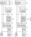
- a in FIG. 4 shows control-plane protocol stacks of nodes in the multi-hop relay network 1 in the architecture
- B in FIG. 4 shows user-plane protocol stacks of nodes in the multi-hop relay network 1 in the architecture.
- Adap. in FIG. 4 indicates an adaptation layer. It can be learned with reference to FIG. 3 that, an F1AP layer of the RN in FIG. 4 is similar to the S1-AP layer of the RN in FIG. 3 , and F1AP layers of the DU and the CU in FIG. 4 are similar to the S1-AP layer of the base station in FIG. 3 .
- a peer RRC layer and PDCP layer of the UE are placed on the CU, and a peer RLC layer of the UE is placed on the RN 2.
- the RN 2 In an uplink transmission process, the RN 2 generates a UE-associated F1AP message, and sends the generated F1AP message to the RN 1 through the Un2 interface. Specially, for an uplink RRC message of the UE, after receiving the RRC message of the UE through the Uu interface, the RN 2 processes the RRC message to the RLC layer, carrying an RLC SDU or a PDCP PDU into the F1AP message, and sends the F1AP message to the RN 1.
- the RN 1 After receiving the F1AP message through the Un2 interface, the RN 1 processes the received F1AP message (for example, the RN 1 replaces a UE-associated UE F1AP ID and/or TEID in an F1AP message body with an identifier corresponding to the UE on the Un1 interface, and other content remains unchanged), sends the processed F1AP message to the DU through the Un1 interface.
- the DU processes the received F1AP message (for example, the DU replaces the UE-associated UE F1AP ID and/or TEID in the F1AP message body with an identifier corresponding to the UE on the F1 interface, and other content remains unchanged), and sends the processed F1AP message to the CU through the F1 interface.
- the CU processes the received F1AP message (for example, the CU extracts an RRC message from the F1AP message and performs RRC layer processing; optionally, before performing the RRC layer processing, the CU first performs PDCP processing).
- the CU In a downlink transmission process, the CU generates a UE-associated F1AP message, and sends the F1AP message to the DU through the F1 interface.
- the DU processes the received F1AP message (for example, the DU replaces a UE-associated UE F1AP ID and/or TEID, on the F1 interface, in the F1AP message body with the identifier corresponding to the UE on the Un1 interface, and other content remains unchanged), and sends the processed F1AP message to the RN 1 through the Un1 interface.
- the CU adds the RRC message to the F1AP message, and sends the F1AP message to the DU.
- the RN 1 processes the received F1AP message (for example, the RN 1 replaces a UE-associated UE F1AP ID and/or TEID, on Un1, in the F1AP message body with an identifier corresponding to the UE on the Un2 interface, and other content remains unchanged), and sends the processed F1AP message to the RN 2 through the Un2 interface.
- the RN 2 processes the received F1AP message, for example, extracts a downlink RRC message from the F1AP message, performs processing of the peer RLC layer of the UE on the extracted downlink RRC message, and then sends the downlink RRC message to the UE through the Uu interface.
- a peer PDCP layer of UE is placed on a CU, and a peer RLC layer of the UE is placed on an RN 2.
- the RN 2 receives data, such as data carried over a UE DRB, of the UE through a Uu interface, processes the received data to the RLC layer, encapsulates an RLC SDU/PDCP PDCU into GTP-U data, and sends the GTP-U data to an RN 1 through a Un2 interface.
- the RN 1 processes the received GTP-U data (for example, the RN 1 replaces a TEID corresponding to the UE on the Un2 interface with a TEID corresponding to the UE on a Un1 interface, and content of data of the UE remains unchanged), and sends the processed GTP-U data to a DU through the Un1 interface.
- the DU processes the received GTP-U data (for example, the DU replaces a GTP TEID with a corresponding TEID on an F1 interface, and the content of the data of the UE remains unchanged), and sends the processed GTP-U data to the CU through the F1 interface.
- the CU processes the received GTP-U data (for example, the CU extracts the data of the UE, and the data of the UE may be a PDCP PDU/RLC SDU), and performs PDCP layer processing.
- the CU In a downlink transmission process, the CU encapsulates the data (for example, a DRB PDCP PDU) of the UE into GTP-U data, and sends the GTP-U data to the DU through the F1 interface.
- the DU processes the received GTP-U data (for example, the DU replaces a TEID corresponding to the UE on the F1 interface with a TEID corresponding to the UE on the Un1 interface, and the content of data of the UE remains unchanged), and sends the processed GTP-U data to the RN 1 through the Un1 interface.
- the RN 1 processes the received GTP-U data (for example, the RN 1 replaces a TEID corresponding to the UE on the Un1 interface with a TEID corresponding to the UE on the Un2 interface, and the content of data of the UE remains unchanged), and sends the processed GTP-U data to the RN 2 through the Un2 interface.
- the RN 2 processes the received GTP-U data, for example, extracts a PDCP PDU/RLC SDU from the GTP-U data, performs processing of the peer RLC layer of the UE on the GTP-U data, and sends the GTP-U data to the UE through the Uu interface.
- each node in a data transmission path can perceive information about each UE, maintain a context of the UE, and manage the UE and collect statistics on data of the UE, to ensure QoS of the UE.
- a UE identifier (for example, a UE F1AP ID/TEID) is maintained by each transmission channel. For example, a UE identifier on the Un2 interface is allocated by the RN 2 or the RN 1, a UE identifier on the Un1 interface is allocated by the RN 1 or the DU, and a UE identifier on the F1 interface is allocated by the DU or the CU.
- an intermediate forwarding node on two transmission channels needs to replace identifiers of UEs on the two transmission channels (optionally, the intermediate forwarding node determines/maintains a mapping relationship between the identifiers of the UEs on two transmission channels).
- an F1AP message/GTP-U data needs to be parsed and encapsulated, thereby reducing a forwarding speed of UE signaling/data.
- a in FIG. 5 shows control-plane protocol stacks of nodes in a multi-hop relay network 1 in the architecture
- B in FIG. 5 shows user-plane protocol stacks of nodes in the multi-hop relay network 1 in the architecture.
- a node other than an RN 2 receives data sent by a previous node/next node of the node, the node does not need to process/parse data at an F1AP protocol layer/GTP-U protocol layer, but directly forwards the data.
- a in FIG. 6 shows control-plane protocol stacks of nodes in a multi-hop relay network 1 in the architecture
- B in FIG. 6 shows user-plane protocol stacks of nodes in the multi-hop relay network 1 in the architecture.
- the node does not need to process/parse data at an F1AP protocol layer/GTP-U protocol layer, but directly forwards the data.
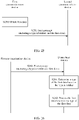
- an embodiment of this application provides a data transmission method. After obtaining first data, a first communications device (or a chip in a first communications device) sends, to a second communications device, a first message that includes the first data and a type identifier used to indicate a type of the first data.
- the first data may be at least one of user plane data (for example, a PDCP PDU of a terminal), a status report, a control plane message, and an RRC message of the terminal. It can be learned that for different types of data, in the data transmission method provided in this embodiment of this application, a unified message format is used for transmission. In this way, a time for each node in a multi-hop relay network to process a message in the format can be effectively reduced.
- the second communications device in this embodiment of this application may directly determine the type of the first data based on the type identifier, and further process the first message by using a method corresponding to the type of the first data, thereby further improving processing efficiency of each node in the multi-hop relay network.
- the first communications device in this embodiment of this application may be an intermediate forwarding node, a serving node of the terminal, a donor base station, or a DU in a donor base station system. If the first communications device is the intermediate forwarding node, the second communications device is a previous-hop device or a next-hop device of the intermediate forwarding node. If the first communications device is the serving node of the terminal, the second communications device is a previous-hop device of the serving node of the terminal. If the first communications device is the donor base station or the DU in the donor base station system, the second communications device is a next-hop device of the first communications device.
- the data transmission method provided in this embodiment of this application is applicable to a communications system.
- the communications system may be a 5G system, an LTE system, or another communications system including at least one RN. This is not specifically limited in this embodiment of this application.
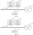
- Both the donor base station and any relay node in FIG. 2 may be the first communications device.
- the communications system includes a terminal 70, an RN 71, an RN 72, and a donor base station system 73.
- the terminal 70 communicates with the RN 72 through a Uu interface
- the RN 72 communicates with the RN 71 through a Un2 interface
- the RN 71 communicates with the donor base station system 73 through a Un1 interface.
- FIG. 7 is merely an example of the communications system provided in this embodiment of this application, and does not specifically limit the communications system.
- both the RN 71 and the RN 72 may provide a service for a plurality of terminals, or the communications system may include at least one RN between the RN 71 and the RN 72.
- the terminal 70 in this embodiment of this application may be a mobile phone (a mobile phone 800 shown in FIG. 8 ), a tablet computer, a personal computer (Personal Computer, PC), a personal digital assistant (Personal Digital Assistant, PDA), a smartwatch, a netbook, a wearable electronic device, or the like that can implement data transmission with the RN 72 on a control plane and a user plane.
- a specific form of the device is not specially limited in this embodiment of this application.
- the mobile phone 800 may specifically include components such as a processor 801, a radio frequency (Radio Frequency, RF) circuit 802, a memory 803, a touchscreen 804, a Bluetooth apparatus 805, one or more sensors 806, a wireless fidelity (Wireless Fidelity, Wi-Fi) apparatus 807, a positioning apparatus 808, an audio frequency circuit 809, a peripheral interface 810, and a power supply apparatus 811. These components may perform communication by using one or more communications buses or signal cables (not shown in FIG. 8 ).
- a hardware structure shown in FIG. 8 does not constitute a limitation on the mobile phone, and the mobile phone 800 may include more or fewer components than those shown in the figure, may combine some components, or may have different component arrangements.
- the following describes all components of the mobile phone 800 in detail with reference to FIG. 8 .
- the processor 801 is a control center of the mobile phone 800.
- the processor 801 is connected to parts of the mobile phone 800 through various interfaces and cables, runs or executes an application program stored in the memory 803, and invokes data stored in the memory 803, to perform various functions of the mobile phone 800 and process data.
- the processor 801 may include one or more processing units.
- the processor 801 may further include a fingerprint verification chip, configured to verify a collected fingerprint.
- the radio frequency circuit 802 may be configured to send and receive a radio signal in an information receiving and sending process or a call process. Particularly, after receiving downlink data from a base station, the radio frequency circuit 802 may send the downlink data to the processor 801 for processing, and sends related uplink data to the base station.
- the radio frequency circuit includes but is not limited to an antenna, at least one amplifier, a transceiver, a coupler, a low noise amplifier, a duplexer, and the like.
- the radio frequency circuit 802 may further communicate with another device through wireless communication.
- the wireless communication may use any communication standard or protocol, including but not limited to a global system for mobile communications, a general packet radio service, code division multiple access, wideband code division multiple access, long term evolution, an email, a short message service, and the like.
- the memory 803 is configured to store the application program and the data.
- the processor 801 performs various functions and data processing of the mobile phone 800 by running the application program and the data that are stored in the memory 803.
- the memory 803 mainly includes a program storage area and a data storage area.
- the program storage area may store an operating system, and an application program required by at least one function (for example, a sound playback function or an image processing function).
- the data storage area may store data (for example, audio data or a phone book) created when the mobile phone 800 is used.
- the memory 803 may include a high-speed random access memory (RAM), and may further include a non-volatile memory such as a magnetic disk storage device, a flash memory, or another volatile solid-state storage device.
- the memory 803 may store various operating systems such as an iOS operating system and an Android operating system.
- the memory 803 may be independent, and is connected to the processor 801 by using the communications bus; or the memory 803 may be integrated with the processor 801.
- the touchscreen 804 may specifically include a touchpad 804-1 and a display 804-2.
- the touchpad 804-1 can collect a touch event performed by a user of the mobile phone 800 on or near the mobile phone 800 (for example, an operation performed by the user on the touchpad 804-1 or near the touchpad 804-1 by using a finger or any suitable object such as a stylus), and send collected touch information to another component (such as the processor 801).
- the touch event of the user near the touch panel 804-1 may be referred to as floating touch.
- the floating touch may mean that the user does not need to directly touch the touch panel to select, move, or drag a target (for example, an icon), and instead, the user only needs to be near a device to implement a desired function.
- the touchpad 804-1 may be implemented in a plurality of types such as a resistive type, a capacitive type, an infrared type, and a surface acoustic wave type.
- the display 804-2 may be configured to display information entered by the user or information provided for the user, and menus of the mobile phone 800.
- the display 804-2 may be configured in a form such as a liquid crystal display or an organic light emitting diode.
- the touchpad 804-1 may cover the display 804-2. After detecting the touch event on or near the touchpad 804-1, the touchpad 804-1 transmits the touch event to the processor 801 to determine a type of the touch event. Then the processor 801 may provide a corresponding visual output on the display 804-2 based on the type of the touch event.
- the touchpad 804-1 and the display 804-2 are used as two independent components to implement input and output functions of the mobile phone 800 in FIG.
- the touchpad 804-1 and the display 804-2 may be integrated to implement the input and output functions of the mobile phone 800.
- the touchscreen 804 is formed by stacking a plurality of layers of materials. In this embodiment of this application, only the touchpad (layer) and the display screen (layer) are displayed, and another layer is not recorded in this embodiment of this application.
- the touchpad 804-1 may be disposed on a front side of the mobile phone 800 in a full panel form
- the display screen 804-2 may also be disposed on the front side of the mobile phone 800 in a full panel form. In this way, a bezel-less structure can be implemented on the front side of the mobile phone.
- the mobile phone 800 may further have a fingerprint recognition function.
- a fingerprint recognizer 812 may be disposed on a back side of the mobile phone 800 (for example, below a rear-facing camera), or a fingerprint recognizer 812 may be configured on the front side of the mobile phone 800 (for example, below the touchscreen 804).
- a fingerprint collection device 812 may be disposed on the touchscreen 804 to implement the fingerprint recognition function.
- the fingerprint collection device 812 and the touchscreen 804 may be integrated to implement the fingerprint recognition function of the mobile phone 800.
- the fingerprint collection device 812 is disposed on the touchscreen 804, and may be a part of the touchscreen 804, or may be disposed on the touchscreen 804 in another manner.
- a main component of the fingerprint collection device 812 is a fingerprint sensor.
- the fingerprint sensor may use any type of sensing technology, including but not limited to an optical, capacitive, piezoelectric, or ultrasonic sensing technology.
- the mobile phone 800 may further include a Bluetooth apparatus 805, configured to implement data exchange between the mobile phone 800 and another short-range device (for example, a mobile phone or a smartwatch).
- the Bluetooth apparatus may be an integrated circuit, a Bluetooth chip, or the like.
- the mobile phone 800 may further include at least one type of sensor 806, such as a light sensor, a motion sensor, and another sensor.
- the light sensor may include an ambient light sensor and a proximity sensor.
- the ambient light sensor may adjust luminance of the display of the touchscreen 804 based on intensity of ambient light.
- the proximity sensor may power off the display when the mobile phone 800 is moved to an ear.
- an accelerometer sensor can detect a value of an acceleration in each direction (usually, three axes), can detect a value and a direction of gravity in a static state, and can be used in an application for identifying a mobile phone posture (such as switching between a landscape orientation and a portrait orientation, a related game, and magnetometer posture calibration), a function related to vibration identification (such as a pedometer and a strike), and the like.
- Other sensors such as a gyroscope, a barometer, a hygrometer, a thermometer, and an infrared sensor may also be disposed in the mobile phone 800. Details are not described herein.
- the Wi-Fi apparatus 807 is configured to provide the mobile phone 800 with network access that complies with a Wi-Fi-related standard protocol.
- the mobile phone 800 may access a Wi-Fi access point by using the Wi-Fi apparatus 807, to help the user send and receive an email, browse a web page, access streaming media, and the like.
- the Wi-Fi apparatus 807 provides a wireless broadband internet access for the user.
- the Wi-Fi apparatus 807 may alternatively be used as a Wi-Fi wireless access point, and may provide Wi-Fi network access for another device.
- the positioning apparatus 808 is configured to provide a geographic location for the mobile phone 800. It may be understood that the positioning apparatus 808 may be specifically a receiver of a positioning system such as a global positioning system (Global Positioning System, GPS), a BeiDou navigation satellite system, or a Russian GLONASS. After receiving the geographic location sent by the positioning system, the positioning apparatus 808 sends this information to the processor 801 for processing, or sends this information to the memory 803 for storage. In some other embodiments, the positioning apparatus 808 may alternatively be a receiver of an assisted global positioning system (Assisted Global Positioning System, AGPS). The AGPS system assists the positioning apparatus 808 as an assisted server, to implement ranging and positioning services.
- AGPS assisted Global Positioning System
- the assisted positioning server communicates with a device such as the positioning apparatus 808 (namely, the GPS receiver) of the mobile phone 800 by using a wireless communications network, to provide positioning assistance.
- the positioning apparatus 808 may be alternatively a positioning technology based on a Wi-Fi access point.
- Each Wi-Fi access point has a globally unique MAC address, and the device can scan and collect a broadcast signal of a surrounding Wi-Fi access point when Wi-Fi is enabled. Therefore, the device can obtain a MAC address broadcast by the Wi-Fi access point.
- the device sends such data (for example, the MAC address) that can identify the Wi-Fi access point to a location server by using a wireless communications network.
- the location server retrieves a geographic location of each Wi-Fi access point, calculates a geographic location of the device with reference to strength of the Wi-Fi broadcast signal, and sends the geographic location of the device to the positioning apparatus 808 of the device.
- the audio circuit 809, a speaker 813, and a microphone 814 may provide an audio interface between the user and the mobile phone 800.
- the audio circuit 809 may convert received audio data into an electrical signal and transmit the electrical signal to the speaker 813.
- the speaker 813 converts the electrical signal into a sound signal for output.
- the microphone 814 converts a collected sound signal into an electrical signal.
- the audio circuit 809 receives the electrical signal, converts the electrical signal into audio data, and outputs the audio data to the RF circuit 802 to send the audio data to, for example, another mobile phone, or outputs the audio data to the memory 803 for further processing.
- the peripheral interface 810 is configured to provide various interfaces for an external input/output device (for example, a keyboard, a mouse, an external display, an external memory, or a subscriber identification module card).
- an external input/output device for example, a keyboard, a mouse, an external display, an external memory, or a subscriber identification module card.
- the peripheral interface 810 is connected to the mouse by using a universal serial bus (Universal Serial Bus, USB) interface, and the peripheral interface 810 is connected, by using a metal contact on a card slot of the subscriber identification module card, to the subscriber identification module (Subscriber Identification Module, SIM) card provided by a telecommunications operator.
- the peripheral interface 810 may be configured to couple the external input/output peripheral device to the processor 801 and the memory 803.
- the mobile phone 800 may communicate with another device in a device group through the peripheral interface 810.
- the mobile phone 800 may receive, through the peripheral interface 810, display data sent by another device for display. This is not limited in this embodiment of this application.
- the mobile phone 800 may further include the power supply apparatus 811 (for example, a battery and a power management chip) that supplies power to the components.
- the battery may be logically connected to the processor 801 by using the power management chip, so that functions such as charging, discharging, and power consumption management are implemented by using the power supply apparatus 811.
- the mobile phone 800 may further include a camera (a front-facing camera and/or a rear-facing camera), a flash, a micro projection apparatus, a near field communication (Near Field Communication, NFC) apparatus, and the like. Details are not described herein.
- a camera a front-facing camera and/or a rear-facing camera
- a flash a flash
- a micro projection apparatus a near field communication (Near Field Communication, NFC) apparatus, and the like. Details are not described herein.
- NFC Near Field Communication
- FIG. 9 is a schematic composition diagram of an RN according to an embodiment of this application.
- the RN may include at least one processor 91, a memory 92, a transceiver 93, and a bus 94.
- the processor 91 is a control center of the RN, and may be a processor, or may be a collective name of a plurality of processing elements.
- the processor 91 is a CPU, or an application-specific integrated circuit (Application Specific Integrated Circuit, ASIC), or one or more integrated circuits configured to implement this embodiment of this application, for example, one or more microprocessors (Digital Signal Processor, DSP) or one or more field programmable gate arrays (Field Programmable Gate Array, FPGA).
- DSP Digital Signal Processor
- FPGA Field Programmable Gate Array
- the processor 91 may implement various functions of the RN by running or executing a software program stored in the memory 92 and invoking data stored in the memory 92.
- the processor 91 may include one or more CPUs, such as a CPU 0 and a CPU 1 shown in FIG. 9 .
- the RN may include a plurality of processors, for example, the processor 91 and a processor 95 shown in FIG. 9 .
- Each of the processors may be a single-core processor (single-CPU) or may be a multi-core processor (multi-CPU).
- the processor herein may refer to one or more devices, circuits, and/or processing cores configured to process data (for example, a computer program instruction).
- the memory 92 may be a read-only memory (Read-Only Memory, ROM) or another type of static storage device that can store static information and an instruction, a random access memory (Random Access Memory, RAM) or another type of dynamic storage device that can store information and an instruction, or may be an electrically erasable programmable read-only memory (Electrically Erasable Programmable Read-Only Memory, EEPROM), a compact disc read-only memory (Compact Disc Read-Only Memory, CD-ROM) or another compact disc storage, an optical disc storage (including a compact disc, a laser disc, an optical disc, a digital versatile disc, a Blu-ray disc, or the like), a magnetic disk storage medium or another magnetic storage device, or any other medium that can be configured to carry or store expected program code in a form of an instruction or a data structure and that can be accessed by a computer. However, this is not limited thereto.
- the memory 92 may exist independently, and be connected to the processor 91 by using the bus 94
- the memory 92 is configured to store a software program that performs the solution of this application, and the processor 91 controls execution of the software program.
- the transceiver 93 is configured to communicate with another device or a communications network.
- the transceiver 93 is configured to communicate with the communications network, such as the Ethernet, a radio access network (radio access network, RAN), or a wireless local area network (Wireless Local Area Networks, WLAN).
- the transceiver 93 may include all or a part of a baseband processor, and may further optionally include an RF processor.
- the RF processor is configured to send and receive an RF signal.
- the baseband processor is configured to process a baseband signal converted from the RF signal or a baseband signal to be converted into the RF signal.
- the bus 94 may be an industry standard architecture (Industry Standard Architecture, ISA) bus, a peripheral component interconnect (Peripheral Component Interconnect, PCI) bus, an extended industry standard architecture (Extended Industry Standard Architecture, EISA) bus, or the like.
- the bus may be classified into an address bus, a data bus, a control bus, and the like. For ease of representation, only one thick line is used to represent the bus in FIG. 9 , but this does not mean that there is only one bus or only one type of bus.
- a device structure shown in FIG. 9 does not constitute a limitation on the RN.
- a quantity of components included may be greater or less than that shown in the figure, or some components are combined, or component arrangements are different.
- the donor base station system 73 in this embodiment of this application may be an independent donor base station, and the donor base station may be a base station (Base Station, BS) or a base station controller in wireless communication, or the like.
- the donor base station may include a DU 730 and a CU 731. Because the donor base station system 73 may include the DU 730 and the CU 731, the DU 730 and the CU 731 are represented by dashed-line boxes in FIG. 7 .
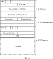
- main functions of the donor base station system 73 include one or more of the following functions: radio resource management, IP header compression and user data stream encryption, MME selection when a terminal is attached, routing of user plane data to an SGW, paging message organization and sending, broadcast message organization and sending, measurement for mobility or scheduling, measurement report configuration, and the like.
- a name of the donor base station may be different.
- the name of the donor base station is an evolved NodeB (evolved NodeB, eNB or eNodeB).
- the name of the donor base station is NodeB (Node B).
- the name of the donor base station is gNB. With evolution of communications technologies, the name may change.
- the donor base station may be another apparatus that provides a wireless communication function for a terminal device.
- FIG. 10 shows a hardware structure of the donor base station.
- the donor base station may include at least one processor 101, a memory 102, a transceiver 103, and a bus 104.
- the processor 101 may include one or more CPUs, such as a CPU 0 and a CPU 1 in FIG. 10 .
- the donor base station may include a plurality of processors, for example, the processor 101 and a processor 105 shown in FIG. 10 .
- a device structure shown in FIG. 10 does not constitute a limitation on the donor base station.
- a quantity of components included may be greater or less than that shown in the figure, or some components are combined, or component arrangements are different.
- a unified message format is used for transmission.
- a time for each node in a multi-hop relay network to process a message in the format can be effectively reduced. Therefore, RNs and the donor base station system in this embodiment of this application all have a function of supporting generation/parsing of messages in the same format.
- an independent protocol layer having a corresponding function is added to protocol stacks of the RNs and the donor base station system, or a corresponding function is added to an existing protocol layer (for example, an RLC layer or a PDCP layer), to support the function of generating/parsing the messages in the same format.
- an existing protocol layer for example, an RLC layer or a PDCP layer
- an independent protocol layer having a corresponding function is added to a protocol stack of the DU, or a corresponding function is added to an existing protocol layer (for example, an RLC layer).
- the added protocol layer may be referred to as an integrated access and backhaul (Integrated Access link and Backhaul link, IAB) function protocol layer, or may have another name. This is not specifically limited in this embodiment of this application.
- IAB Integrated Access link and Backhaul link
- the IAB function protocol layer is used as an example for description in this embodiment of this application.
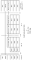
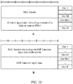
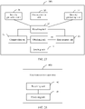
- FIG. 11A and FIG. 11B show control-plane protocol stacks and user-plane protocol stacks of nodes according to an embodiment of this application.
- the donor base station system 73 includes the DU 730 and the CU 731
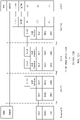
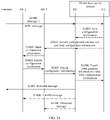
- FIG. 12A and FIG. 12B show control-plane protocol stacks and user-plane protocol stacks of nodes in a hop-by-hop architecture according to an embodiment of this application
- FIG. 13A and FIG. 13B show control-plane protocol stacks and user-plane protocol stacks of nodes in an end-to-end architecture from an RN 72 to the DU 730 according to an embodiment of this application.
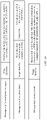
- FIG. 14A and FIG. 14B show control-plane protocol stacks and user-plane protocol stacks of nodes according to an embodiment of this application.
- FIG. 15A and FIG. 15B show control-plane protocol stacks and user-plane protocol stacks of nodes according to an embodiment of this application.
- an F1 interface provides a method for interaction between a CU and a DU in a base station system, and a signaling procedure is defined in an F1AP to support a function of the F1 interface.
- a similar interface may be established between an RN and a donor base station system/previous-hop RN, and is used for interaction between the RN and the donor base station system/previous-hop RN.
- a name of the interface (which may be the F1 interface, or another interface that has a similar function of transferring UE-associated information to perform UE context management, UE configuration, and the like) is not limited.
- the interface is referred to as an F1-like interface in this embodiment of this application.
- the unified message format means including a type identifier and first data.
- the type identifier is used to indicate a type of the first data.
- the type of the first data includes at least one of user plane data, a status report, a control plane message, and an RRC message of a terminal.
- the first data in this embodiment of this application is the user plane data.
- the user plane data includes a PDCP PDU/RLC PDU/H-RLC PDU belonging to a DRB of a terminal, and the user plane data of the terminal may be similar to a data packet in a GTP-U format.
- H-RLC is one of a plurality of parts (which may be referred to as subprotocol layers) into which that an existing RLC protocol layer is divided according to functions, and is responsible for completing functions such as an ARQ.
- the IAB function protocol layer may transmit the user plane data in one of the following two manners.
- Manner 1 The user plane data (the PDCP PDU RLC PDU/H-RLC PDU belonging to the DRB of the terminal) is carried on a user plane of the F1-like interface for transmission.
- a user-plane protocol stack of the F1-like interface may include any one or any combination of a plurality of the following: a GTP-U layer, a UDP layer, and an IP layer.
- Manner 2 The user plane data (the PDCP PDU RLC PDU/H-RLC PDU belonging to the DRB of the terminal) is directly carried in the IAB function protocol layer for transmission.
- the user plane data is directly carried in a PDU of the IAB function protocol layer.
- the first message in this embodiment of this application further includes first indication information, and the first indication information is used to indicate a DRB of the terminal to which the user plane data belongs.
- the first indication information may be user plane transport layer information, and the user plane transport layer information may include any one or any combination of a plurality of pieces of the following information: a TEID, a source IP address, a destination IP address, a source port number, and a destination port number.
- the first message sent by the IAB function protocol layer needs to include an additional terminal identifier, DRB identifier information, and the like.
- the first indication information may include any one or a combination of a plurality of pieces of the following information: a TEID, a source IP address, a destination IP address, a source port number, a destination port number, a terminal identifier, and a DRB identifier.
- the first message further includes a global sequence number (Sequence Number, SN) of the user plane data.
- the global SN of the user plane data is classified into an SN of the user plane data in the DRB of the terminal and an SN of the user plane data in a DRB of the RN.
- the SN of the user plane data in the DRB of the terminal is generated by the donor base station system and the terminal/a serving node of the terminal and is maintained by a donor base station, an intermediate forwarding node, and the serving node of the terminal.
- the intermediate forwarding node does not change the SN, and therefore the SN is referred to as a global SN.
- the SN of the user plane data in the DRB of the terminal may be a PDCP SN and/or an HFN of the terminal, or may be an RLC SN of the terminal.
- the two SNs are generated by the donor base station system (corresponding to downlink data) and the terminal (corresponding to uplink data), or may be GTP-U SNs or newly defined SNs, for example, SNs inside the IAB function protocol layer, referred to as IAB SNs of the terminal for short.
- the two SNs are generated by the donor base station system (corresponding to downlink data) and the serving node (corresponding to uplink data) of the terminal.
- the SN of the user plane data in the DRB of the RN is an SN maintained between the RN and the donor base station system that are directly connected through an air interface or between the RNs, and referred to as an RN DRB SN for short.
- the RN DRB SN may be an RN PDCP SN (if a Un interface protocol stack has an RN PDCP protocol layer, and the IAB function protocol layer is below the RN PDCP protocol layer, or the IAB function protocol layer and the RN PDCP protocol layer are disposed together, the RN PDCP SN may be identified in the IAB function protocol layer), or may be a newly defined SN, for example, an SN inside the IAB function protocol layer, referred to as an RN IAB SN for short.
- Data for example, a PDU session and a QoS flow (whose identifier is referred to as a QoS flow identifier, QFI)) of the terminal generally has a requirement on a QoS parameter.
- the QoS parameter is, for example, a GBR (Guranteed Bit Rate, guaranteed bit rate), a latency (latency)/an end-to-end latency, a jitter, a packet loss rate, a forwarding priority, and a voice MOS value.
- the donor base station system sends the QoS parameter to the RN and the intermediate node that serve the terminal.
- Radio Access Network Radio Access Network
- each RAN node may limit a rate of a non-GBR service of the terminal, so that the rate does not exceed an AMBR (Aggregate Maximum Bit Rate, aggregate maximum bit rate) value. Therefore, when the data of the terminal passes through the donor base station system on a RAN side and one or more RNs, a RAN node not only needs to learn of a corresponding QoS parameter requirement, but also needs to monitor data of the terminal, to ensure that a corresponding QoS requirement can be met. In this case, each RN needs to be capable of identifying data of different terminals (and identifying different DRBs and/or QFIs that belong to one terminal).
- AMBR Average Maximum Bit Rate, aggregate maximum bit rate
- the donor base station system directly notifies each RN of the GBR, and each RN guarantees the GBR.
- each RN may independently ensure the AMBR.
- the donor base station system needs to negotiate with each RN, or the donor base station system notifies each RN after determining the latency, so that each RN ensures a latency requirement of a Un/Uu interface associated with the RN.
- the first data in this embodiment of this application is the status report.
- the status report is used to indicate a transmission status of a DRB data packet of the terminal, the intermediate forwarding node, and the serving node of the terminal.
- the transmission status of the DRB data packet refers to a transmission status and/or a packet loss status of the DRB data packet.
- a peer RLC layer of a terminal 70 is disposed on an RN 72, and a peer PDCP layer of the terminal 70 is disposed on a donor base station system 73. Therefore, an RLC status report and a PDCP status report in this embodiment of this application are different from existing status reports.
- data of the terminal for example, a DRB of the terminal is used as a granularity in an L2 architecture
- Un interface for example, a DRB of the RN
- the RN adds the data of the terminal to the DRB of the terminal through the Uu interface, and sends the data of the terminal to the terminal. Therefore, an RLC SN of the terminal on the Uu interface and an RLC SN of the RN on the Un interface are independently numbered. Therefore, a status report fed back for the RLC SN can feed back only one segment of the Un interface or an RLC transmission status of the Uu interface.
- the RN may fail to obtain the PDCP SN of the terminal. Therefore, the RN cannot feed back a PDCP status report based on the PDCP SN of the terminal. For example, in FIG. 4 , FIG. 5 , and FIG.
- the PDCP PDU of the terminal is carried and transmitted over the Un interface after being processed by using a GTP-U/UDP/IP protocol stack.
- the GTP-U data packet is encrypted at an IP layer, and an encryption manner is not perceived by an RN 1, the RN 1 cannot learn a PDCP SN of the terminal. Even if the PDCP SN can be obtained, GTP-U data packet also needs to be parsed, and additional processing overheads are introduced.
- a PDCP entity of the RN DRB further processes the PDCP PDU. However, the PDCP entity needs to encrypt user plane data.
- an end-to-end SN between the donor base station system and the RN serving the terminal may be defined, and both the intermediate forwarding node and the RN serving the terminal may feed back the status report based on the SN.
- the end-to-end SN between the donor base station system and the RN serving the terminal is referred to as a global SN of the terminal, for example, an IAB SN.
- the global SN may be the PDCP SN (the intermediate forwarding node may perceive the PDCP SN of the terminal), or may be the RLC SN.
- the RLC function is an ARQ function
- the global SN is an RLC SN used for the ARQ.
- the PDCP SN is an SN corresponding to a PDCP SDU/PDU.
- the RLC SN is an SN corresponding to an RLC SDU (or an RLC SDU segment).
- the status report includes the global SN of the user plane data carried on the DRB of the terminal.
- the first data further includes fifth indication information used to indicate the DRB of the terminal.
- the status report may be a status report of the DRB of the terminal, and is used to provide information about whether the user plane data carried on the DRB of the terminal is successfully sent/received.
- the status report may be the status report of the DRB of the terminal served by the RN, or may be a status report of a DRB of a terminal served by another RN (in this case, the RN is not directly connected to the terminal through an air interface, but forwards data of the terminal).
- a transmission granularity of the status report is the DRB of the terminal.
- the fifth indication information may be at least one of a TEID, a source IP address, a destination IP address, a source port number, a destination port number, a terminal identifier, and a DRB identifier.
- the status report of the DRB of the terminal may be specific to one DRB of the terminal.
- the status report includes fifth indication information corresponding to the terminal.
- the status report transmitted at the IAB function protocol layer may be specific to a plurality of DRB s of the terminal.
- the status report includes a plurality of pieces of fifth indication information associated with the terminal.
- the status report transmitted at the IAB function protocol layer may be specific to all DRBs of the terminal.
- the status report includes sixth indication information used to indicate the terminal.
- the sixth indication information may be any one or any combination of a plurality of pieces of the following information: a cell radio network temporary identifier C-RNTI, a cell identifier, a terminal context identifier, an F1 interface identifier of the terminal, an F1-like interface identifier of the terminal, a TEID, and a terminal identifier in another format.
- the status report transmitted at the IAB function protocol layer may be specific to all DRBs of the terminal
- the status report further includes all fifth indication information associated with the terminal. If the status report does not include all fifth indication information associated with the terminal, the status report may include a plurality of status reports that are of DRBs of the terminal and that are arranged in a specific sequence. The sequence may be preset in a protocol, or may be arranged in descending order or ascending order of DRB identifiers.
- the status report of the DRB of the terminal may be an RLC status report/PDCP status report of the terminal.
- the DRB status report of the terminal may be a combination of one or more RLC status reports/PDCP status reports of the terminal that are generated by the IAB function protocol layer.
- the RN when the RN generates the status report of the DRB of the terminal served by the RN, or generates the status report of the DRB of the terminal served by the another RN, the status report of the DRB of the terminal further includes the global SN of the terminal.
- the donor base station system/intermediate forwarding node may determine the transmission status of the data packet of the terminal based on the global SN.
- the status report of the DRB of the terminal includes a status of a downlink data packet and/or a status of an uplink data packet.
- a status of a data packet may include any one or any combination of a plurality of pieces of the following content: a largest successfully sent/received global SN (Highest Successfully Delivered Sequence Number), a largest global SN and a smallest global SN of a transmission hole (referring to one data packet or a plurality of data packets with consecutive SNs that is/are not successfully sent/received), a transmission hole sequence number, a largest consecutively successfully sent/received global SN, a largest global SN and a smallest global SN of a successfully transmitted data chunk, a sequence number of a successfully transmitted data chunk, a successfully sent global SN, a lost global SN, a largest sent/received global SN, a terminal identifier, a DRB identifier, and a TEID.
- specific information included in the status report of the DRB of the terminal is not limited to the SN, and for example, may further include a global SN of a first lost packet and a global SN of a next downlink packet to be sent.
- all the SNs may be inferred by using information included in the DRB status report of the terminal.
- a global SN of a first lost packet is a smallest global SN in a transmission hole
- a global SN of a next downlink packet to be sent is a largest downlink global SN plus 1. Therefore, possible cases are not listed one by one herein.
- the status report of the DRB of the terminal may alternatively be in a form of a bitmap (bitmap), and each bit corresponds to a status of whether a data packet corresponding to an SN is lost.
- bitmap bitmap
- the largest successfully sent global SN is an SN corresponding to a packet with a largest SN in data packets that are of a DRB of the terminal and that are successfully received by the next-hop node/a terminal served by the next-hop node when data of the DRB of the terminal is transmitted between a node that generates the status report and the next-hop node/the terminal served by the node.
- the largest consecutively successfully sent global SN is an SN corresponding to a packet with a largest SN in data packets with consecutive SNs that are of a DRB of the terminal and that are successfully received by the next-hop node/a terminal served by the next-hop node when data of the DRB of the terminal is transmitted between a node that generates the status report and the next-hop node/the terminal served by the node.
- the transmission hole sequence number in this embodiment of this application is a sequence number corresponding to each transmission hole when there may be more than one transmission hole and different transmission holes need to be indicated.
- successful sending means that a transmit end receives an acknowledge (Acknowledge, ACK) feedback from a receive end.
- the lost data packet means that a non-acknowledge (Non Acknowledge, NACK) feedback is received from a peer end, or no ACK feedback is received from a peer end.
- successful receiving means that a receive end successfully receives data sent by a transmit end.
- the successfully transmitted data chunk is one successfully received data packet or a plurality of successfully received data packets with consecutive SNs in data packets with global SNs that are greater than the largest consecutively successfully sent global SN.
- the sequence number of the successfully transmitted data chunk is a sequence number corresponding to each successfully transmitted data chunk when there may be more than one successfully transmitted data chunk and different successfully transmitted data chunks need to be indicated.
- the status report may be a status report of a DRB of an RN, and is used to provide information about whether the user plane data carried on the DRB of the RN is correctly sent/received.
- the status report may be a status report of a DRB of a Un interface of the RN, or may be a status report generated by an RN/DU for a DRB of a Un interface of a next-hop RN of the RN/DU.
- a transmission granularity of the status report is the DRB of the RN.
- the status report of the DRB of the RN may be a status report of a DRB of at least one terminal carried on each of the at least one DRB of the RN.
- the status report of the DRB of the RN further includes a terminal identifier and/or a DRB identifier, or includes an identifier (for example, a TEID, a UE context identifier, or an identifier in another format) used to identify the DRB of the terminal.
- the status report of the DRB of the RN does not include the DRB identifier
- the status report of the DRB of the RN may include status reports of DRBs of a plurality of terminals arranged in a specific sequence.
- the arrangement sequence herein may be preset in a protocol, or may be arranged in descending order or ascending order of DRB identifiers.
- a DRB of each RN corresponds to one IAB function protocol layer entity (entity).
- the status report of the DRB of the RN does not identify DRBs of terminals carried by the RN, and feeds back a transmission status of the DRB of the RN by carrying an SN in the DRB of the RN.
- the status report of the DRB of the RN includes any one or any combination of a plurality of pieces of the following content: a largest successfully sent/received RN DRB SN, a largest RN DRB SN and a smallest RN DRB SN of a transmission hole (referring to one data packet or a plurality of data packets with consecutive SNs that is/are not successfully sent/received), a transmission hole sequence number, a largest consecutively successfully sent/received RN DRB SN, a largest RN DRB SN and a smallest RN DRB SN of a successfully transmitted data chunk, a sequence number of a successfully transmitted data chunk sequence number, a largest sent/received RN DRB SN, a successfully sent RN DRB SN, a lost RN DRB SN, an RN identifier, a DRB identifier, and an RN DRB identifier.
- the status report of the DRB of the RN may include status reports of all DRBs of the Un interface of the RN, or may be status reports of all DRBs of a next-hop RN of the RN.
- the DRB status report of the RN further includes the RN identifier and/or the DRB identifier, or includes information used to identify the RN DRB. If the DRB identifier is not carried, the DRB status report of the RN may include status reports of DRBs of a plurality of RNs that are arranged in a specific sequence. The sequence herein may be preset in a protocol, or may be arranged in descending order or ascending order of DRB identifiers.
- the RN may also generate an RLC status report of the Un interface of the DRB of the RN.
- the status report is referred to as an RN RLC status report.
- the RN RLC status report includes any one or a combination of the following content: a largest successfully sent RN RLC SN, a successfully sent RN RLC SN, a lost RN RLC SN, a largest RN RLC SN and a smallest RN RLC SN of a transmission hole, a transmission hole sequence number, an RN identifier, and a DRB identifier.
- the RN generates a status report of the RN at the IAB function protocol layer based on the RN RLC status report.
- the status report of the RN includes a part or all of the RN RLC status report of the RN. It should be noted that, in this case, one RN has one IAB function protocol layer entity, and all DRBs of the RN correspond to the IAB function protocol layer entity.
- the status report of the RN further includes the RN identifier and/or the DRB identifier, or includes information used to identify the RN DRB. If the status report of the RN does not include the DRB identifier, the status report may include a plurality of RN RLC status reports arranged in a specific sequence.
- the status report of the RN includes only an RN RLC status report corresponding to one RN DRB.
- the IAB function protocol layer entity may be per RN DRB, in other words, one RN DRB corresponds to one IAB function protocol layer entity.
- the status report in this embodiment of this application may be periodically reported, or may be reported by event triggering. This is not specifically limited in this embodiment of this application.
- the periodic reporting may be used by a data anchor (for example, the donor base station system) to delete, based on the status report, a data packet that has been successfully sent.
- a data anchor for example, the donor base station system
- a peer PDCP entity referred to as a PDCP entity of the terminal for short
- the PDCP entity of the terminal deletes the PDCP PDU
- the IAB function protocol layer buffers the PDCP PDU of the downlink terminal.
- the received status report feeds back that the terminal has correctly received the PDCP PDU
- the PDCP PDU is deleted.
- periodic reporting may be further used inside the data anchor.
- the PDCP entity of the terminal sends the PDCP PDU by using a lower layer
- the PDCP entity of the terminal continues to buffer the PDCP PDU.
- the data anchor instructs the PDCP entity of the terminal to delete the PDCP PDU.
- the event may be: terminal handover, radio link failure (Radio Link Failure, RLF) of the terminal, RN handover, RLF of the RN, or reception of a polling indication (for example, the polling indication is indication information generated by the IAB function protocol layer).
- RLF Radio Link Failure
- the source node of the terminal may feed back the status report of the terminal or status reports of DRBs of one or more terminals to the data anchor, so that the data anchor forwards, to the target node, data that is not successfully sent to the terminal.
- the data anchor may be a common previous-hop RN or previous-but-n-hop (n>0) RN of the source node and the target node, or a common donor base station of the source node and the target node (for example, a peer PDCP of the terminal is placed in the donor base station, and the PDCP PDU that is not successfully received by the terminal may be further buffered in the donor base station).
- a peer PDCP of the terminal is placed in the donor base station, and the PDCP PDU that is not successfully received by the terminal may be further buffered in the donor base station.
- relay transmission needs to be performed on data of the terminal at the data anchor.
- the data anchor is a previous-hop RN/Donor base station directly connected to the source node and the target node through an air interface
- the source node may feed back the RLC status report of the terminal to the data anchor.
- the source node may be an RN
- the target node may be an RN or a donor base station.
- the target node and the data anchor are the same node.
- the data anchor needs to send, to the target node, data that is not successfully received by the terminal, so that the target node sends the data to the terminal.
- the data anchor needs to learn of information about the target node, and the learning may be performed in the following manners: manner 1: The source node notifies the data anchor, for example, the source node negotiates with the target node in advance by using a handover preparation process, and notifies the data anchor of the information about the target node; manner 2: The target node notifies the data anchor, for example, after the terminal is accessed by the target node, the target node notifies the data anchor, so that the data anchor switches a data path of the terminal from the source node to the target node.
- manner 1 The source node notifies the data anchor, for example, the source node negotiates with the target node in advance by using a handover preparation process, and notifies the data anchor of the information about the target node
- manner 2 The target node notifies the data anchor, for example, after the terminal is accessed by the target node, the target node notifies the data anchor, so that the data anchor switches a data path of the terminal from the source node to the target
- the terminal may send a status report on a DRB transmission status of the terminal, to explicitly notify the target node/data anchor of a data packet that is not successfully received by the target node/data anchor.
- a status report on a DRB transmission status of the terminal to explicitly notify the target node/data anchor of a data packet that is not successfully received by the target node/data anchor.
- An advantage of this method is that, when the serving node or the intermediate forwarding node of the terminal feeds back a status report for the DRB of the terminal, a data packet that is not successfully received by the terminal and that is indicated in the status report may have been successfully received by the terminal, but an acknowledge (ACK) feedback is not sent in time. Therefore, the terminal may provide a more accurate status report after accessing the target node, and this avoids air interface resource waste caused by repeated data transmission.
- ACK acknowledge
- the terminal sends the status report to the data anchor, so that the data anchor can be prevented from sending, to the target node, a data packet that has been successfully received by the terminal but for which an acknowledge (ACK) feedback has not been sent.
- the terminal sends the status report to the target node, so that the target node can be prevented from sending, to the terminal, the data packet that has been successfully received by the terminal but for which the acknowledge (ACK) feedback has not been sent.
- the terminal performs RRC connection reestablishment in a cell provided by the target node
- the target node notifies an original serving node that the RLF occurs on the terminal
- the original serving node may forward the data of the terminal to the target node.
- the original serving node of the terminal may feed back the status report of the terminal or status reports of DRBs of a plurality of terminals to the data anchor, so that the data anchor forwards, to the target node, data that is not successfully sent to the terminal.
- the data anchor may be a common previous-hop RN or previous-but-n-hop (n>0) RN of the original serving node and the target node, or a common donor base station of the original serving node and the target node (for example, a peer PDCP of the terminal is placed in the donor base station, and the PDCP PDU that is not successfully received by the terminal may be further buffered in the donor base station).
- a peer PDCP of the terminal is placed in the donor base station, and the PDCP PDU that is not successfully received by the terminal may be further buffered in the donor base station.
- relay transmission needs to be performed on data of the terminal at the data anchor.
- the original serving node may feed back the RLC status report of the terminal to the data anchor.
- the original serving node may be an RN
- the target node may be an RN or a donor base station.
- the target node and the data anchor are the same node.
- the data anchor needs to send, to the target node, data that is not successfully received by the terminal, so that the target node sends the data to the terminal.
- the data anchor needs to learn of information about the target node, and the learning may be performed in the following manners: manner 1: The original serving node notifies the data anchor, for example, the original serving node configures the target node for the terminal in advance, and notifies the data anchor of the information about the target node in advance; manner 2: The target node notifies the data anchor, for example, after the terminal is accessed by the target node, the target node notifies the data anchor, so that the data anchor switches a data path of the terminal from the original serving node to the target node.
- manner 1 The original serving node notifies the data anchor, for example, the original serving node configures the target node for the terminal in advance, and notifies the data anchor of the information about the target node in advance
- manner 2 The target node notifies the data anchor, for example, after the terminal is accessed by the target node, the target node notifies the data anchor, so that the data anchor switches a data path of the terminal from the original serving node to the target node
- the terminal may send a status report on a DRB transmission status of the terminal, to explicitly notify the target node/data anchor of a data packet that is not successfully received by the target node/data anchor.
- the source node of the RN may feed back the status report of the RN or status reports (which carry data of a terminal served by the RN) of DRBs of one or more RNs to the data anchor, so that the data anchor forwards, to the target node, data that is not successfully sent to the RN.
- relay transmission does not continue to be performed on data (all DRBs or some DRBs) of some terminals by using the RN, or some terminals are no longer served by the RN.
- the source node needs to feed back status reports of DRBs of the terminals to the data anchor.
- the data anchor is a common previous-hop RN or previous-but-n-hop (n>0) RN of the source node and the target node, or a common donor base station of the source node and the target node (for example, a peer PDCP of the terminal is placed in the donor base station, and the PDCP PDU that is not successfully received by the terminal may be further buffered in the donor base station).
- relay transmission needs to be performed on data of the RN (for example, data of the terminal served by the RN and data of a next-hop RN served by the RN) at the data anchor.
- the source node may feed back an RLC status report of the RN to the data anchor.
- the source node may be an RN
- the target node may be an RN or a donor base station.
- the target node and the data anchor are the same node.
- the data anchor needs to send, to the target node, data that is not successfully received by the terminal, so that the target node sends the data to the RN.
- the data anchor needs to learn of information about the target node, and the learning may be performed in the following manners: manner 1: The source node notifies the data anchor, for example, the source node negotiates with the target node in advance by using a handover preparation process, and notifies the data anchor of the information about the target node; manner 2: The target node notifies the data anchor, for example, after the RN is accessed by the target node, the target node notifies the data anchor, so that the data anchor switches a data path of the RN from the source node to the target node.
- manner 1 The source node notifies the data anchor, for example, the source node negotiates with the target node in advance by using a handover preparation process, and notifies the data anchor of the information about the target node
- manner 2 The target node notifies the data anchor, for example, after the RN is accessed by the target node, the target node notifies the data anchor, so that the data anchor switches a data path of the RN from the source no
- the RN may send a status report on a data transmission status of the RN, to explicitly notify the target node/data anchor of a data packet that is not successfully received by the target node/data anchor.
- An advantage of this method is that, when the serving node or the intermediate forwarding node of the RN feeds back a status report for the data of the RN, a data packet that is not successfully received by the RN and that is indicated in the status report may have been successfully received by the RN, but an acknowledge (ACK) feedback is not sent in time. Therefore, the RN may provide a more accurate status report after accessing the target node, and this avoids air interface resource waste caused by repeated data transmission.
- ACK acknowledge
- the RN sends the status report to the data anchor, so that the data anchor can be prevented from sending, to the target node, a data packet that has been successfully received by the RN but for which an acknowledge (ACK) feedback has not been sent.
- the RN sends the status report to the target node, so that the target node can be prevented from sending, to the RN, the data packet that has been successfully received by the RN but for which the acknowledge (ACK) feedback has not been sent.
- the RN performs RRC connection reestablishment in a cell provided by the target node
- the original serving node learns that the RLF occurs on the RN, and the original serving node may forward the data of the RN to the target node.
- the original serving node of the RN may feed back the status report of the RN or status reports of DRBs of a plurality of RNs to the data anchor, so that the data anchor forwards, to the target node, data that is not successfully sent to the RN.
- relay transmission does not continue to be performed on data (all DRBs or some DRBs) of some terminals by using the RN, or some terminals are no longer served by the RN.
- the source node needs to feed back status reports of DRBs of the terminals to the data anchor.
- the data anchor is a common previous-hop RN or previous-but-n-hop (n>0) RN of the original serving node and the target node, or a common donor base station of the original serving node and the target node (for example, a peer PDCP of the terminal is placed in the donor base station, and the PDCP PDU that is not successfully received by the terminal may be further buffered in the donor base station).
- a peer PDCP of the terminal is placed in the donor base station, and the PDCP PDU that is not successfully received by the terminal may be further buffered in the donor base station.
- relay transmission needs to be performed on data of the RN at the data anchor.
- the original serving node may feed back the RLC status report of the RN to the data anchor.
- the original serving node may be an RN
- the target node may be an RN or a donor base station.
- the target node and the data anchor are the same node.
- the data anchor needs to send, to the target node, data that is not successfully received by the RN, so that the target node sends the data to the RN.
- the data anchor needs to learn of information about the target node, and the learning may be performed in the following manners: manner 1: The original serving node notifies the data anchor, for example, the original serving node configures the target node for the RN in advance, and notifies the data anchor of the information about the target node in advance; manner 2: The target node notifies the data anchor, for example, after the RN is accessed by the target node, the target node notifies the data anchor, so that the data anchor switches a data path of the RN from the original serving node to the target node.
- manner 1 The original serving node notifies the data anchor, for example, the original serving node configures the target node for the RN in advance, and notifies the data anchor of the information about the target node in advance
- manner 2 The target node notifies the data anchor, for example, after the RN is accessed by the target node, the target node notifies the data anchor, so that the data anchor switches a data path of the RN from the original serving no
- the RN may send a status report on a data transmission status of the RN, to explicitly notify the target node/data anchor of a data packet that is not successfully received by the target node/data anchor.
- the previous-hop node of the RN needs to route upwards the received status report as data of a node that sends the status report, and send the data to the data anchor.
- UE 3 accesses an RN 3, and performs data transmission with the donor base station by using an RN 2 and an RN 1, and the RN 2 generates a status report of a DRB of the RN 3 on the Un3 interface.
- the peer IAB function protocol layer entity of the RN 3 on the RN 2 generates the status report, and sends the status report to the peer IAB function layer entity of the RN 1 on the RN 2, so that the RN 2 sends the status report to the RN 1 through the Un2 interface.
- the peer IAB function layer entity of the RN 1 on the RN 2 generates the status report.
- the pee IAB function protocol layer entity of the RN 3 on the RN 2 informs the peer IAB function layer entity of the RN 1 on the RN 2 of a sending/receiving status of a data packet on the Un3 interface. Because a plurality of DRBs of a terminal may have different mapping manners on different Un interfaces, there may be a plurality of implementations of a routing manner of the status report.
- the IAB function protocol layer entity is a per RN DRB
- a DRB 1 and a DRB 2 of a terminal are carried on a DRB 1 of the RN 3 on the Un3 interface, but on the Un2 interface, the DRB 1 of the terminal is carried on a DRB 1 of the RN 2, and the DRB 2 of the terminal is carried on a DRB 2 of the RN 2.
- the status report sent by the RN 2 on the Un2 interface needs to feed back a transmission status of the DRB 1 of the terminal on the DRB 1 of the RN 2, and feed back the transmission status of the DRB 2 of the terminal on the DRB 2 of the RN 2.
- the RN 1 when receiving the DRB that feeds back the DRB transmission status of the terminal, the RN 1 needs to transmit, on the DRB of the RN 1, the transmission status of the DRB of the terminal carried on the DRB of the RN 1.
- the intermediate forwarding node when forwarding the status report, the intermediate forwarding node needs to reassemble the status report, aggregate, based on an RN DRB of the intermediate forwarding node, DRB status reports of the terminal included in the status report, and aggregate, into one status report, DRB statuses of the terminal carried on one RN DRB, and transmit the status report on the RN DRB.
- the first data in this embodiment of this application is the control plane message.
- the F1-like interface may transmit an interface control plane message, and the message is similar to the F1AP and is referred to as an FlAP-like signaling procedure/message.
- the F1AP-like signaling procedure and message are consistent with the F1AP, or are extended based on the F1AP. In this way, an existing interface procedure can be directly reused, and standardization work is reduced.
- the FlAP-like message may be classified into two types: a common message (Common message, or Non UE-associated) and a UE-associated (UE associated) message.
- a common message Common message, or Non UE-associated
- UE-associated UE associated
- a logical F1-like connection exists between the RN and the donor base station system, different logical F1-like connections exist between different RNs and the donor base station system, and FlAP-like messages of different RNs may be distinguished by using the carried logical F1-like connections.
- the logical F1-like connection may be identified by using any one or a combination of the following information: control plane transport layer information (if any), second indication information, an identifier of the terminal on the F1-like interface (UE F1-like ID), and third indication information.
- the control plane transport layer information is information carried in a transport layer protocol of the F1-like interface.
- the control plane transport layer information includes an IP address of the donor base station system and/or an IP address of the RN.
- the control plane transport layer information includes: a port number of the donor base station system and/or a port number of the RN, an SCTP stream identifier (Stream Identifier), an SCTP payload protocol identifier (Payload Protocol Identifier), and the like.
- control plane transport layer information may include any one or any combination of a plurality of pieces of the following information: the IP address of the donor base station system, the IP address of the RN, the port number of the donor base station system, the port number of the RN, the SCTP stream identifier, the SCTP PPI, and the like.
- the second indication information is used to indicate an RN that establishes the F1-like interface with the donor base station system.
- the second indication information may be a UE identifier (for example, a C-RNTI, an S-TMSI, or a GUTI) when the RN accesses a network as UE, or may be an F1-like interface identifier (for example, a UE F1AP ID or a UE FlAP-like ID) allocated by a previous-hop RN to the RN when the RN accesses a network as UE, or may be an RN ID obtained after the RN is handed over from a UE mode to an RN mode after the RN accesses a network as UE (optionally, the RN ID may be configured by an OAM system, assigned by the donor base station system, or preconfigured).
- a UE identifier for example, a C-RNTI, an S-TMSI, or a GUTI
- F1-like interface identifier for example, a UE F1AP ID or a UE FlAP-like ID
- the RN ID may be
- the second indication information may have a same format as a DU identifier.
- the second indication information may be a global identifier, and includes an RN local identifier and a quantity of RN hops.
- the RN local identifier may be allocated by a previous-hop node (for example, an RN or a DU in a donor base station system) of the RN.
- the third indication information is used to indicate an F1-like interface, to identify logical F1-like connections of different RNs.
- a terminal-associated logical F1-like connection may be established for a terminal served by the RN.
- the terminal-associated logical F1-like connection may identify different terminals by using any one or any combination of a plurality of pieces of the following information: fourth indication information used to indicate the terminal and an identifier of a serving node of the terminal.
- the fourth indication information may be any one or any combination of a plurality of pieces of the following information: an F1-like interface UE ID (a UE FlAP-like ID), a C-RNTI, a cell ID, a context identifier (Context ID), and the like. Further, optionally, the fourth indication information is a combination of a terminal identifier and an RN identifier.
- the terminal accesses a cell provided by an RN, the terminal is directly connected to an RN through an air interface, the RN provides a Uu interface for the terminal, or the RN provides a radio resource for air interface transmission for the terminal, in this embodiment of this application, the RN is referred to as an RN serving the terminal, and the terminal is referred to as a terminal served by the RN.
- the first data in this embodiment of this application is the RRC message of the terminal.
- the IAB function protocol layer After obtaining the RRC message of the terminal, the IAB function protocol layer sends the first message including the RRC message of the terminal and a type identifier corresponding to the RRC message.
- the RRC message of the UE may be carried in an FlAP-like message for transmission, or may be directly transmitted by using the IAB function protocol layer, for example, directly carried in a PDU of the IAB function protocol layer.
- the first message may include a target identifier, and the target identifier is used to indicate a serving node of the terminal.
- the first communications device determines, based on the target identifier, a target device of the control plane message or the user plane data, to perform processing and/or forwarding.
- the target identifier may be an identifier of the serving node of the terminal or an IP address of the serving node of the terminal.
- the first message further includes sixth indication information, and the sixth indication information is used to indicate that the first data belongs to the terminal or that the first data is associated with the terminal.
- the type identifier is used to indicate a type of the first data. In this way, a device that receives the first message may perform different processing based on the data type.
- the IAB function protocol layer may be used to transmit any one or any combination of a plurality of the following data types: an FlAP-like control plane message (optionally, the FlAP-like control plane message may be further classified into a common FlAP-like control plane message and a UE-associated FlAP-like control plane message), an RRC message of the terminal, user plane data, a status report of a Uu interface, and a status report of a Un interface.
- a corresponding data type may be further carried, so that a receive end performs processing based on a processing procedure of a corresponding function after identifying the data type.
- the user plane data, the control plane data, the RRC message, and the status report are all referred to as the first data.
- the IAB function protocol layer compresses the first data or sub-information in the first data based on a first preset compression algorithm.
- the sub-information includes at least one of an IP header, an SCTP common header, and information other than target information in an SCTP data chunk, and the target information is at least one of user data, the stream identifier, and the PPI; or the sub-information includes at least one of an IP header, a UDP header, and information other than a TEID in a GTP header.
- the donor base station system/RN when generating the FlAP-like control plane message including a transmission protocol layer information field, the donor base station system/RN compresses the transmission protocol layer information field of the FlAP-like control plane message. When receiving the FlAP-like control plane message, the donor base station system/RN decompresses the transmission protocol layer information field of the FlAP-like control plane message.
- the compression/decompression is performed by the DU.
- FIG. 16 shows a format of an existing SCTP/IP packet and a format of each field in the SCTP/IP packet.
- fields that carry useful information include: a source IP address and a destination IP address, which are used for IP addressing; a source port number and a destination port number; a stream identifier, used to identify a common message and a UE-associated message; and a PPI, used to indicate a corresponding AP type (for example, an S1AP is 18, an NGAP is 60, and an F1AP is 62).
- the FlAP-like message body needs to be carried in a user data field in FIG. 16 .
- Information about a field other than an FlAP-like message body is static.
- the intermediate forwarding node may compress the information.
- compressing the information specifically includes compressing the information into zero, or deleting/peeling the compressed information.
- a peer end may be notified of the compressed information in another manner (for example, a control plane message).
- decompression includes restoring the compressed information.
- the compressed information is not used by the peer end, and correspondingly the peer end does not need to perform decompression processing.
- the first sub-information of the first data is compressed.
- the first sub-information may be an IP header (for example, an IPv6 header part in FIG. 16 ), or an IP header and an SCTP common header, or a part other than user data in an IP header, an SCTP common header, and an SCTP data chunk, or a part other than user data and a stream identifier in an IP header, an SCTP common header, and an SCTP data chunk, or a part other than user data, a stream identifier, and a PPI in an IP header, an SCTP common header, and an SCTP data chunk.
- IP header for example, an IPv6 header part in FIG. 16
- an IP header and an SCTP common header or a part other than user data in an IP header, an SCTP common header, and an SCTP data chunk, or a part other than user data and a stream identifier
- PPI in an IP header, an SCTP common header, and an SCTP data chunk.
- the compression and the decompression are performed by nodes at two ends of the F1-like interface (for example, a donor base station and an RN that establish the interface), and does not need to be performed by the intermediate forwarding node (for example, an RN that performs relay transmission for the FlAP-like control plane message).
- nodes at two ends of the F1-like interface for example, a donor base station and an RN that establish the interface
- the intermediate forwarding node for example, an RN that performs relay transmission for the FlAP-like control plane message.
- the first preset compression algorithm is preconfigured (for example, specified in a protocol), or is configured by the donor base station system/an operation and management entity (Operation and management, OAM).
- the donor base station system may configure the first preset compression algorithm for the RN through an RRC message of the RN, may configure the first preset compression algorithm for the RN in an F1-like interface establishment process, or may configure the first preset compression algorithm for the RN after establishment of the F1-like interface is completed.
- the donor base station system sends a compression activation/deactivation indication to the RN, to indicate that the RN starts/stops using the compression function.
- a compression indication is carried in a data packet, to indicate that the FlAP-like control plane message is compressed.
- the compression indication is 1-bit information, "1" indicates being compressed, and "0" indicates not being compressed.
- the compression indication is carried in a packet header of the IAB function protocol layer.
- a data packet of the IAB function protocol layer of the FlAP-like control plane message carries a message identifier, to identify a common message or a UE-associated message.
- the IAB function protocol layer data packet that carries the FlAP-like control plane message carries an AP type, to indicate that a corresponding AP type is FlAP-like.
- the DU peels the transmission protocol layer field of the F1AP message received by the F1 interface, and reserves only an F1AP message body, and the F1AP message body is transmitted to the RN on the Un interface.
- the DU uses the FlAP-like control plane message as an F1AP message body transmitted on the F1 interface, a transmission field is added, and the FlAP-like control plane message is transmitted on the F1 interface.
- the user plane data is transmitted in the manner 1, the user plane data is carried on the user plane of the F1-like interface for transmission.
- the PDCP PDU of the terminal is carried in the GTP-U data packet.
- the donor base station system/RN compresses the transmission protocol layer information field of the user plane data when generating the user plane data that includes the transmission protocol layer information field.
- the donor base station system/RN decompresses the transmission protocol layer information field of the user plane data.
- the compression/decompression is performed by the DU.
- FIG. 19 shows a format of an existing GTP-U data packet and a format of each field in the GTP-U data packet.
- Fields of useful information carried in the GTP-U data packet include: a source IP address and a destination IP address, which are used for IP addressing; a source port number and a destination port number; and a TEID, used to identify a DRB of UE.
- Information about a field other than a UE PDCP PDU is static. If the intermediate forwarding node does not need to obtain the information included in the field, the intermediate forwarding node may compress the information. Specially, compressing the information specifically includes compressing the information into zero, or deleting/peeling the compressed information.
- a peer end may be notified of the compressed information in another manner (for example, a control plane message).
- decompression includes restoring the compressed information.
- the compressed information is not used by the peer end, and correspondingly the peer end does not need to perform decompression processing.
- the first sub-information of the first data is compressed.
- the first sub-information may be an IP header, or an IP header and a UDP header, or a part other than a TEID in an IP header, a UDP header, and a GTP header, or a UDP header and a GTP header.
- the FlAP-like user plane data includes the TEID or the first indication information. For example, if the TEID carried in the F1-like user plane data packet corresponds to the TEID on the F1 interface, in other words, for DRBs of same UE, when the DRBs are transmitted on the F1-like interface and the F1 interface, a same TEID is used.
- the DU peels the transmission protocol layer field from the GTP-U data packet received by the F1 interface, and reserves only the TEID and the PDCP PDU of the UE, and the TEID and the PDCP PDU of the UE are transmitted to the RN on the Un interface.
- the DU uses the FlAP-like user plane data packet as an F1-U data packet transmitted on the F1 interface, a transmission field is added, and the FlAP-like user plane data packet is transmitted on the F1 interface.
- the IAB function protocol layer provides integrity protection and/or encryption for transmitted first data (which may be, a control plane message, user plane data, or a status report).
- security protection is performed in downlink by using the pee PDCP layer of the donor base station system of the terminal, and security protection is performed in uplink by using the PDCP layer of the terminal. Therefore, no further security protection is needed.
- the FlAP-like control plane message because the FlAP-like control plane message carries configuration information (for example, cell configuration information) of the RN and the donor base station system and terminal-associated configuration information (for example, QoS information of the terminal), security protection needs to be performed to prevent the FlAP-like control plane message from being stolen or tampered with. Therefore, the IAB function protocol layer may perform security protection on the FlAP-like control plane message. Optionally, security protection may also be performed on another data type.
- a specific implementation of security protection may be encryption and/or integrity protection.
- an IAB function protocol layer at a transmit end performs encryption and/or integrity protection on data on which security protection needs to be performed, and an IAB function protocol layer at a receive end performs decryption and/or integrity check on the data.
- the transmit end and the receive end need to use a same encryption/integrity protection key and algorithm, and the encryption/integrity protection key and algorithm may be the same or different.
- an RN PDCP security protection function may be used for the security protection function.
- an RN PDCP encryption key and algorithm and an RN PDCP integrity protection key and algorithm are used, to perform security protection on data on which security protection needs to be performed.
- FIG. 17 shows a format of a first message of the protocol stacks.
- FIG. 18 shows a format of a first message of the protocol stacks.
- an IAB function protocol layer and a PDCP layer are independent protocol layers.
- the IAB function protocol layer is used as a part of an RN RLC layer, for example, used as a sub-layer of the RN RLC layer.
- data of the IAB function protocol layer is carried in an RN RLC PDU, for example, as a content part of an RLC PDU.
- an IAB function protocol layer data indication (for example, a 1-bit (bit) indicator bit) is added to the RN RLC PDU, to indicate that the RN RLC PDU includes the data of the IAB function protocol layer.
- the IAB function protocol layer data indication may be included in an RLC header.
- a in FIG. 20 shows a format of a data packet of an existing RLC layer, and B shows a format of a data packet of an RLC layer integrated with an IAB function according to an embodiment of this application.
- "Oct" represents a byte.
- an IAB function protocol layer may be disposed in a PDCP layer.
- the IAB function protocol layer is a part of an RN PDCP layer, for example, used as a sub-layer of the RN PDCP layer.
- data of the IAB function protocol layer is carried in an RN PDCP PDU, for example, as a content part of a PDCP PDU.
- an IAB function protocol layer data indication (for example, a 1-bit indicator bit) is added to the RN PDCP PDU, to indicate that the RN PDCP PDU includes the data of the IAB function protocol layer.
- the IAB function protocol layer data indication may be included in a PDCP header.
- a MAC-I in FIG. 21 is an integrity protection parity bit.
- IAB function protocol layers are added to protocol stacks of an RN and a donor base station system, and the IAB function protocol layers can implement the foregoing functions 1 to 8.
- the IAB function protocol layers of the RN and the donor base station system need to be initially configured.
- FIG. 22 shows a procedure for configuring an IAB function protocol layer in a scenario in which an RN 1 accesses a network.
- a donor base station system in the following procedure may be an independent donor base station, or may include a CU and a DU. If the donor base station system is an independent donor base station, interaction between the CU and the DU in FIG. 22 is internal interaction of the donor base station system. It should be noted that whether the donor base station system performs CU-DU splitting does not affect processing of the RN 1. Specifically, when the RN 1 sends a message to the donor base station system, if the donor base station system includes a CU and a DU, the DU receives, through an air interface (for example, a Un1 interface), a message sent by the RN 1, and further may need to send the message to the CU.
- an air interface for example, a Un1 interface
- the RN 1 When the RN 1 receives a message sent by the donor base station system, if the donor base station system includes a CU and a DU, the message received by the RN 1 may be generated by the DU and sent to the RN 1 through an air interface, or generated by the CU and sent to the DU through an F1 interface, and then processed by the DU and sent to the RN 1 through an air interface.
- a configuration method includes the following steps.
- the donor base station system includes a CU and a DU
- an F1 interface is established between the DU and the CU, and the F1 interface is used to indicate whether each of the DU and the CU has a function of supporting an IAB function protocol layer.
- the donor base station system includes a CU and a DU, this step is required.
- the DU indicates, to the CU by using an F1AP message, that the DU has a function of supporting the IAB function protocol layer.
- the F1AP message includes information used to indicate that the DU has the IAB function protocol layer.
- the CU is similar to the DU, and details are not described herein again.
- the donor base station system generates first configuration information associated with an RN access network, and sends the first configuration information.
- the donor base station system includes a CU and a DU, and both the CU and the DU can provide a service for the RN, for example, the DU supports the function of the IAB function protocol layer, and the donor base station system including the CU and the DU can route control plane signaling and user plane data of the RN to a core network node serving the RN, it is determined that the donor base station system can provide a service for the RN, and the donor base station system generates the first configuration information.
- the first configuration information may include an access control parameter used to indicate the RN, and may also include information (for example, a random access resource, a PUCCH, a configuration of a signal used for measurement, and a measurement reporting configuration) associated with a configuration of a radio resource dedicated to the RN.
- information for example, a random access resource, a PUCCH, a configuration of a signal used for measurement, and a measurement reporting configuration
- the donor base station system After generating the first configuration information, the donor base station system (for example, the DU) broadcasts the first configuration information through an air interface.
- the donor base station system for example, the DU
- the first configuration information is a system message.
- S2202 The RN 1 sends a message 1 to the donor base station system, to request to access a network.
- the RN 1 may initiate a random access procedure, and send the message 1 to request to establish an RRC connection (specifically including scenarios of establishment, resume, and reestablishment).
- the message 1 may include an RRC connection request (RRC Connection Request) message, an RRC connection resume request (RRC Connection Resume Request) message, or an RRC connection reestablishment request (RRC Connection Reestablishment Request) message.
- RRC Connection Request RRC Connection Request
- RRC Connection Resume Request RRC Connection Resume Request
- RRC Connection Reestablishment Request RRC Connection Reestablishment Request
- the RN 1 may further send an RN indication, so that the donor base station system identifies that a terminal requesting to establish the RRC connection is not a common terminal, but an RN.
- the RN indication may be included in a MAC data packet, and is used to be interpreted by the DU.
- the RN 1 performs access by using a random access resource dedicated to the RN, so that the DU can identify that a terminal initiating random access is not a common terminal, but an RN.
- S2203 (optional): When the donor base station system includes a CU and a DU, the DU sends, to the CU through an F1 interface, the RRC message included in the message 1.
- the DU determines whether access of the RN is allowed. If the DU determines that access of the RN 1 is not allowed, the DU sends a notification message to the CU through the F1 interface, to instruct the CU to reject access of the RN 1, so that the CU sends, to the RN 1, an RRC message used to indicate that access is rejected.
- the DU instructs the CU to reject access of the RN 1 may be indicated explicitly or implicitly.
- the DU If the DU does not determine whether access of the RN 1 is allowed, after receiving the message 1, the DU forwards the RRC message of the RN 1 in the message 1 to the CU through the F1 interface.
- S2204 The donor base station system sends a message 2 to the RN 1.
- the message 2 is used to indicate whether access of the RN 1 is allowed.
- the message 2 may include an RRC connection setup (RRC Connection Setup) message, an RRC connection resume (RRC Connection Resume) message, an RRC connection reestablishment (RRC Connection Reestablishment) message, an RRC connection reject (RRC Connection Reject) message, an RRC connection resume reject (RRC Connection Resume Reject) message, or an RRC connection reestablishment reject (RRC Connection Re-establishment Reject) message.
- RRC connection setup RRC Connection Setup
- RRC Connection Resume RRC connection resume
- RRC Connection Reject RRC connection reject
- the donor base station system includes a CU and a DU
- the CU determines that the RN requests access to a device, and further determines whether access of the RN 1 is allowed, to generate the message 2 indicating that access of the RN 1 is allowed or rejected, and sends the message 2 to the RN 1 by using the DU.
- the message 2 generated by the CU is used to indicate that access of the RN 1 is allowed.
- the message 2 may include an RRC connection setup (RRC Connection Setup) message, an RRC connection resume (RRC Connection Resume) message, or an RRC connection reestablishment (RRC Connection Reestablishment) message.
- the CU determines to reject access of the RN 1, the CU generates the message 2 used to indicate that access of the RN 1 is rejected.
- the message 2 may include an RRC connection reject (RRC Connection Reject) message, an RRC connection resume reject (RRC Connection Resume Reject) message, or an RRC connection reestablishment Reject (RRC Connection Reestablishment Reject) message.
- the CU may further receive a notification message sent by the DU, to instruct the CU to reject access of the RN 1, so that the CU generates the message 2 used to indicate that access of the RN 1 is rejected.
- the message 3 is used to indicate that RRC setup is completed.
- the message 3 may include an RRC connection setup complete (RRC Connection Setup Complete) message, an RRC connection resume complete (RRC Connection Resume Complete) message, or an RRC connection reestablishment complete (RRC Connection Reestablishment Complete) message.
- RRC Connection Setup Complete RRC Connection Setup Complete
- RRC Connection Resume Complete RRC Connection Resume Complete
- RRC connection reestablishment complete RRC Connection Reestablishment Complete
- the message 3 further includes an identifier of the RN 1.
- the message 3 herein is merely used to describe a message, and is different from the message 3 in the existing random access process.
- the donor base station system sends a message 4 including second configuration information to the RN 1, to instruct the RN 1 to configure, based on the second configuration information, a peer IAB function protocol layer of the donor base station system.
- the second configuration information includes security configuration information and compression configuration information.
- the message 4 further includes any one or any combination of a plurality of pieces of the following information: a relay mode (relay mode) activation indication, an RB list, a PHY/MAC/RLC configuration of an RB, a PDCP configuration of the RB in a cell group configuration (cellgroupconfig), and QoS information of a DRB.
- a relay mode relay mode
- the PHY/MAC/RLC configuration of the RB is included in cellgroupconfig
- cellgroupconfig further includes a common configuration of an access cell.
- the message 4 may be an RRC connection reconfiguration (RRC Connection Reconfiguration) message, or may be an RRC reconfiguration (RRC Reconfiguration) message.
- RRC Connection Reconfiguration RRC Connection Reconfiguration
- RRC Reconfiguration RRC reconfiguration
- the donor base station system includes a CU and a DU
- the CU after receiving the RRC message in the message 3, the CU sends a message 5 including third configuration information to the DU through the F1 interface, and the third configuration information is used to instruct the DU to complete configuration of the peer IAB function protocol layer of the DU of the RN 1.
- the third configuration information includes any one or a combination of the following information: an anchor key (anchor key), a control plane key, a user plane key, an encryption algorithm, an integrity protection algorithm, key derivation information (for example, a quantity of hops and a counter), a compression activation indication, a compression-into-zero indication, a compression field indication, and a compression algorithm.
- the message 5 may be an F1AP message, for example, a context setup request (UE context setup request) message of the terminal or a context modification request (UE context modification request) message of the terminal.
- a context setup request UE context setup request
- UE context modification request UE context modification request
- the message 5 further includes an RB list of the RN 1 and QoS information corresponding to the DRB.
- the RB list includes an RB identifier.
- the QoS information corresponding to the DRB includes at least one of the following information: a DRB identifier, a QoS parameter of the DRB, and a QoS parameter of a QoS flow carried on the DRB.
- the DU sends a message 6 including fourth configuration information to the CU through the F1 interface, and the message 6 is used to indicate a configuration parameter of the IAB function protocol layer of the RN 1 to the CU, so that the CU generates a corresponding configuration message (for example, an RRC message), and the configuration message is sent to the RN 1.
- a message 6 including fourth configuration information to the CU through the F1 interface
- the message 6 is used to indicate a configuration parameter of the IAB function protocol layer of the RN 1 to the CU, so that the CU generates a corresponding configuration message (for example, an RRC message), and the configuration message is sent to the RN 1.
- the fourth configuration information includes any one or a combination of the following information: an anchor key (anchor key), a control plane key, a user plane key, an encryption algorithm, an integrity protection algorithm, key derivation information (for example, a quantity of hops and a counter), a compression activation indication, a compression-into-zero indication, a compression field indication, and a compression algorithm.
- the message 6 further includes at least one of the following information: the RB list of the RN 1, the PHY/MAC/RLC configuration of the RB, and the cell group configuration (cellgroupconfig).
- Sending the message 5 and/or the message 6 between the CU and the DU may implement the following three manners of configuring a configuration parameter of the IAB function protocol layer in the RN 1.
- Manner 1 The CU determines configuration information of the IAB function protocol layer in the DU, and sends the configuration information to the DU by using the message 5.
- the second configuration information is the third configuration information.
- the DU determines configuration information of the IAB function protocol layer in the DU, and sends the configuration information to the CU by using the message 6, so that the CU generates a corresponding RRC message, to instruct the RN 1 to perform a corresponding configuration.
- the second configuration information is the fourth configuration information.
- Manner 3 The CU determines first sub-configuration information (that is, the third configuration information) of the IAB function protocol layer in the DU, and sends the first sub-configuration information to the DU by using the message 5, and/or the DU determines second sub-configuration information (that is, the fourth configuration information), and sends the second sub-configuration information to the CU by using the message 6.
- the donor base station system (which may be the CU or the DU) obtains the second configuration information based on the first sub-configuration information and the second sub-configuration information.
- the first sub-configuration information may be at least one of an anchor key, key derivation information, and whether compression is being performed
- the second sub-configuration information may be at least one of an encryption algorithm, an integrity protection algorithm, and a compression algorithm.
- the CU needs to obtain capability information (for example, whether the encryption algorithm/an integrity protection algorithm/a compression algorithm is supported) of the RN 1.
- the DU needs to obtain the capability information of the RN 1.
- the capability information may be sent by the RN 1 to the CU by using an RRC message, or may be sent by a core network to the CU through an interface (for example, an NG interface) between the core network and a base station.
- the CU After obtaining the capability information of the RN 1, the CU sends the capability information of the RN 1 to the DU through the F1 interface.
- the RN 1 configures the IAB function protocol layer of the RN 1 based on the second configuration information.
- the RN 1 sends a message 7 to the donor base station system, to request to establish an F1-like interface.
- a method for configuring the IAB function protocol layer of the RN 1 based on the second configuration information by the RN 1 is as follows.
- the message 7 is an RRC message.
- the DU does not parse the message 7, but sends the message 7 to the CU through the F1 interface.
- the CU After receiving the message 7, the CU establishes a corresponding F1 interface for the F1-like interface of the RN 1, and instructs the DU to establish, for the F1-like interface, a transmission channel of a Uu interface between the F1-like interface and the RN 1.
- the message 7 is an IAB function protocol layer/MAC layer/RLC layer/PHY layer message.
- the DU parses the message 7, to establish, for the F1-like interface, a transmission channel of a Uu interface between the F1-like interface and the RN 1.
- the DU establishes, for the F1-like interface, the transmission channel of the Uu interface between the F1-like interface and the RN 1 includes allocating a radio resource, for example, an SRB, a DRB, or an RLC-bearer, used to transmit an F1-like interface message.
- a radio resource for example, an SRB, a DRB, or an RLC-bearer
- the DU requests the CU to establish a corresponding F1 interface for the F1-like interface.
- that the CU establishes the corresponding F1 interface for the F1-like interface includes that the CU considers the RN 1 as a DU, and establishes an F1 interface for the RN 1 between the CU and the DU.
- the DU is responsible for forwarding a message on the F1 interface to the CU or the RN 1.
- the RN 1 enables a base station mode.
- the RN 1 may send a system message or receive a random access request (Random Access Preamble) message from another node.
- the RRC message in this embodiment of this application is an RRC message defined in LTE, and this application is also applicable to a message that is defined in another system and that has a different name from the RRC message but has a same or similar function.
- the steps in this embodiment may also be separately used.
- S2200 and S2201 are optional, and implementation of this solution does not depend on the foregoing two steps.
- S2202 to S2206 are used by the donor base station system to perform admission decision on the RN.
- the donor base station system includes a CU and a DU, the CU and the DU may need to jointly perform admission decision on the RN.
- S2207 and S2208 are used by the donor base station to configure an IAB function for the RN 1.
- the donor base station system includes a CU and a DU
- the configuration needs to be performed jointly by the CU and the DU.
- a peer IAB function layer of the DU of the RN 1 further needs to be configured. Therefore, S2202 to S2206 and S2207 and S2208 may be applied as two independent processes.
- FIG. 23 shows a procedure for configuring an IAB function protocol layer in a scenario in which a node 2 (a terminal or an RN 2) accesses a network through an RN 1.
- a configuration method includes the following steps.
- the RN 1 sends an RRC message in the message 1 to a donor base station system.
- the RN 1 adds the RRC message in the message 1 to an IAB function protocol layer message, and sends the IAB function protocol layer message to the donor base station system.
- the RN 1 determines whether access of the node 2 is allowed. If the RN 1 determines that access of the node 2 is not allowed, the RN 1 sends a notification message to the donor base station system through an F1-like interface, to indicate that access of the node 2 is rejected, so that the donor base station system sends, to the node 2, an RRC message used to indicate access rejection.
- the RN 1 may notify the donor base station that a system rejects access of the node 2 by using an explicit indication or an implicit indication.
- the DU sends, to the CU through an F1 interface, an RRC message received by the DU.
- S2303 The donor base station system sends a message 8 to the node 2.
- the message 8 is used to indicate whether access of the node 2 is allowed.
- the message 8 may include an RRC connection setup (RRC Connection Setup) message, an RRC connection resume (RRC Connection Resume) message, an RRC connection reestablishment (RRC Connection Reestablishment) message, an RRC connection reject (RRC Connection Reject) message, an RRC connection resume reject (RRC Connection Resume Reject) message, or an RRC connection reestablishment reject (RRC Connection Re-establishment Reject) message.
- RRC connection setup RRC Connection Setup
- RRC Connection Resume RRC connection resume
- RRC Connection Reject RRC connection reject
- the donor base station system includes a CU and a DU
- the CU determines whether an RN requests access to a device, and further determines whether access of the node 2 is allowed, to generate the message 8 indicating that access of the node 2 is allowed or rejected, and sends the message 8 to the node 2 by using the DU and the RN 2.
- the CU sends the RRC message in the message 8 to the DU through the F1 interface, the DU forwards the RRC message in the message 8 to the RN 1, and the RN 1 sends the RRC message in the message 8 to the node 2.
- the message 8 generated by the CU is used to indicate that access of the node 2 is allowed.
- the message 8 may include an RRC connection setup (RRC Connection Setup) message, an RRC connection resume (RRC Connection Resume) message, or an RRC connection reestablishment (RRC Connection Reestablishment) message.
- the CU determines to reject access of the node 2
- the CU generates the message 8 used to indicate that access of the node 2 is rejected.
- the message 8 may include an RRC connection reject (RRC Connection Reject) message, an RRC connection resume reject (RRC Connection Resume Reject) message, or an RRC connection reestablishment Reject (RRC Connection Reestablishment Reject) message.
- the message 9 is used to indicate that RRC setup is completed.
- the message 9 may include an RRC connection setup complete (RRC Connection Setup Complete) message, an RRC connection resume complete (RRC Connection Resume Complete) message, or an RRC connection reestablishment complete (RRC Connection Reestablishment Complete) message.
- RRC Connection Setup Complete RRC Connection Setup Complete
- RRC Connection Resume Complete RRC Connection Resume Complete
- RRC connection reestablishment complete RRC Connection Reestablishment Complete
- the message 9 further includes an identifier of the RN, used to indicate that a device that sends the message is the RN, and is not a common terminal.
- the RN 1 sends an RRC message in the message 9 to the donor base station system.
- the RN 1 sends the RRC message in the message 9 to the donor base station system.
- the DU forwards the RRC message in the message 9 to the CU through the F1 interface.
- the donor base station system sends a message 10 including fifth configuration information and/or sixth configuration information to the RN 1, to instruct the RN 1 to perform configuration based on the fifth configuration information and/or the sixth configuration information.
- the donor base station system includes a CU and a DU
- the node 2 is the RN 2
- the CU after receiving the RRC message in the message 9, the CU sends seventh configuration information to the DU through the F1 interface, and the seventh configuration information is used to instruct the DU to perform configuration of the IAB function protocol layer corresponding to the node 2.
- the seventh configuration information includes any one or a combination of the following information associated with the node 2: security configuration information, compression configuration information, and capability information.
- security configuration information any one or a combination of the following information associated with the node 2: security configuration information, compression configuration information, and capability information.
- capability information A manner in which the CU obtains the capability information of the node 2 is similar to a manner in which the CU obtains the capability information of the RN 1, and details are not described herein again.
- the donor base station system includes a CU and a DU
- the node 2 is the RN 2
- the CU after receiving the RRC message in the message 9, the CU sends fifth configuration information to the DU through the F1 interface, and the fifth configuration information is used to instruct the RN 1 to perform configuration of the IAB function protocol layer corresponding to the node 2.
- the fifth configuration information includes any one or a combination of the following information associated with the node 2: security configuration information, compression configuration information, and capability information.
- the fifth configuration information and the seventh configuration information may be included in different messages.
- the fifth configuration information is included in the message 11
- the seventh configuration information is included in the message 12.
- the message 11 may be included in the message 12.
- the fifth configuration information is the same as the seventh configuration information, or the fifth configuration information is a subset of the seventh configuration information.
- the message 12 may include only the seventh configuration information.
- the CU may further send eighth configuration information to the DU, and the eighth configuration information is used to indicate QoS information of the node 2 to the DU, so that the DU adjusts and updates, based on a QoS requirement of data of the node 2 carried on a DRB of the RN 1, a PHY/MAC/RLC configuration of the DRB of the RN 1, to trigger the CU to send an RRC reconfiguration message to the RN 1 for reconfiguration.
- the CU determines how to map the data of the node 2 to the DRB of the RN 1, and sends the QoS requirement (for example, a QoS parameter of the DRB or a QoS parameter of a QoS flow) of the data of the node 2 to the DU, so that the DU determines whether the PHY/MAC/RLC configuration of the DRB of the RN 1 that carries the data of the node 2 needs to be updated.
- the QoS requirement for example, a QoS parameter of the DRB or a QoS parameter of a QoS flow
- the eighth configuration information includes any one or a combination of the following information: an RB list of the node 2, QoS information corresponding to a DRB of the node 2, a correspondence between the DRB of the node 2 and the DRB of the RN 1, a QoS flow list of the node 2, QoS information corresponding to a QoS flow of the node 2, and a correspondence between the QoS flow of the node 2 and the DRB of the RN 1.
- the QoS flow list includes a QoS flow identifier (QFI for short) and/or a DRB identifier of the node 2.
- the CU may further send sixth configuration information to the DU, to indicate QoS information of the node 2 to the RN 1.
- the sixth configuration information includes any one or a combination of the following information: an RB list of the node 2 and QoS information corresponding to a DRB of the node 2.
- the sixth configuration information may be included in the message 11/message 12.
- the sixth configuration information is a subset of the eighth configuration information.
- the CU sends the eighth configuration information to the DU, and the DU generates the sixth configuration information based on the eighth configuration information.
- the message 11/message 12 may be an F1AP message, or may be a UE context setup request (UE context setup request) or a UE context modification request (UE context modification request) message.
- the UE/RN F1AP ID included in the message 12 is used to determine the RN 1, and can be used to instruct the DU to configure an air interface between the DU and the RN 1.
- the UE/RN F1AP ID included in the message 11 is used to determine the node 2, and can be used to instruct the DU to configure an air interface corresponding to the node 2, and/or forward configuration information to the RN 1, so that the RN 1 configures an air interface between the RN 1 and the node 2.
- both the sixth configuration information and the eighth configuration information include the QoS information of the data of the node 2, and the sixth configuration information and the eighth configuration information may not be completely the same.
- a base station system for example, a CU and/or a DU
- the latency requirement B is included in the seventh configuration information
- the latency requirement C is included in the eighth configuration information.
- the CU does not need to send the fifth configuration information and the seventh configuration information to the DU.
- the node 2 is an RN, and the IAB function protocol layer is hop-by-hop, the DU does not need to configure the IAB function protocol layer corresponding to the node 2, and the RN 1 needs to configure the IAB function protocol layer corresponding to the node 2.
- the CU does not need to send the seventh configuration information, but needs to send the fifth configuration information.
- the IAB function protocol layer is end-to-end, to be specific, when the CU sends an IAB function protocol layer message to the node 2, the RN 1 does not need to process (for example, perform security protection/encryption on) the message. Therefore, the CU does not need to send the fifth configuration information to the RN 1.
- the DU obtains the fifth configuration information and/or the sixth configuration information based on the message 11, to generate a message 10.
- the DU receives the message 12, and processes the message 12 (for example, changes the UE/RN F1AP ID of the F1 interface to an identifier, indicating the node 2, on the F1-like interface, compresses all or some information in the message 12, and performs security protection on all or some information in the message 12, in other words, performs security protection on all or some information in the message 12 based on an encryption algorithm and/or an integrity protection algorithm).
- the RN 1 configures, based on the message 10, the peer IAB function protocol layer of the node 2, and sends a message 13 including ninth configuration information to the donor base station system, to indicate a configuration parameter associated with the node 2 in the donor base station system, so that the donor base station system generates a corresponding configuration message (for example, an RRC message) and sends the configuration message to the RN 1.
- a corresponding configuration message for example, an RRC message
- the ninth configuration information includes any one or a combination of the following information: security configuration information, compression configuration information, an RB list of the node 2, and a PHY/MAC/RLC configuration corresponding to an RB.
- the message 13 may be an FlAP-like message, or may be a message having a function similar to that of a UE context setup response (UE context setup response) message or a UE context modification response (UE context modification response) message.
- the DU sends a message 14 including tenth configuration information to the CU, to indicate a configuration parameter associated with the node 2 to the CU, so that the CU generates a corresponding configuration message (for example, an RRC message) and sends the corresponding configuration message to the node 2.
- a corresponding configuration message for example, an RRC message
- the tenth configuration information includes any one or a combination of the following information: security configuration information, compression configuration information, an RB list of the node 2, and a PHY/MAC/RLC configuration corresponding to an RB.
- the DU sends eleventh configuration information to the CU, and the eleventh configuration information includes any one or a combination of the following information: an RB list of the RN 1 and a PHY/MAC/RLC configuration corresponding to the RB, and is used to instruct the CU to generate a reconfiguration message sent to the RN 1 and change a configuration of the RB of the RN 1.
- the eleventh configuration information may be included in a message 13/message 14.
- the message 13/message 14 may be an F1AP message, or may be a UE context setup response (UE context setup response) message or a UE context modification response (UE context modification response) message.
- a UE/RN F1AP ID in the message 13 is used to determine the node 2, and is used to indicate configuration information of the CU associated with the node 2.
- a UE/RN F1AP ID in the message 14 is used to determine the RN 1, and is used to indicate configuration information of the CU associated with the RN 1.
- a security configuration and/or a compression configuration in the IAB function protocol layer may be determined by the CU (this is applicable to an end-to-end architecture, and the CU is a centralized decision anchor), or determined by the DU (applicable to an end-to-end architecture), or determined by the CU and the DU through negotiation, or determined by the RN 1 (applicable to a hop-by-hop architecture), or determined by the CU and the RN 1 through negotiation, or determined by the DU and the RN 1 through negotiation, or determined by the CU, the DU, and the RN 1 through negotiation.
- a key may be determined by the CU or the DU, and an algorithm may be determined by the RN 1.
- a security configuration and/or compression configuration manner may be implemented by sending the message 10, the message 11, the message 12, the message 13, and the message 14 among the CU, the DU, and the RN 1.
- specific configuration information may be sent in a plurality of sequences.
- the specific configuration information is sent in the sequences described in the foregoing steps, or the DU first sends the eleventh configuration information to the CU and then sends the fifth configuration information/the sixth configuration information to the RN 1. This is not specifically limited in this embodiment of this application.
- S2309 The donor base station system sends a message 15 to the RN 1.
- the message 15 includes one or a combination of the following information: a configuration (for example, security configuration information and compression configuration information) of an IAB function protocol layer corresponding to the node 2, an RB list of the RN 1, a PHY/MAC/RLC configuration of an RB, a PDCP configuration of the RB, and QoS information of a DRB.
- a configuration for example, security configuration information and compression configuration information
- the message 15 may include an RRC connection reconfiguration (RRC Connection Reconfiguration) message or an RRC reconfiguration (RRC Reconfiguration) message.
- RRC Connection Reconfiguration RRC Connection Reconfiguration
- RRC Reconfiguration RRC reconfiguration
- the RN 1 after receiving the message, applies a new configuration, and replies with a configuration completion response message.
- the message 16 includes one or a combination of the following information: a configuration of an IAB function protocol layer (if the node 2 is an RN, an information element appears; otherwise, the information element does not appear), an RN mode activation indication (if the node 2 is an RN, the information element appears; otherwise, the information element does not appear), an RB list of the node 2, a PHY/MAC/RLC configuration of an RB, a PDCP configuration of the RB, and QoS information of a DRB.
- the message 16 may be an RRC connection reconfiguration (RRC Connection Reconfiguration) message or an RRC reconfiguration (RRC Reconfiguration) message.
- the node 2 after receiving the message, applies a new configuration, and replies with a configuration completion response message.
- S2309 may be performed before S2310, or S2310 may be performed before S2309. This is not specifically limited in this embodiment of this application.
- the RN 1 does not parse the message 17, but sends the message 17 to the donor base station system through an F1-like interface.
- the donor base station system After receiving the message 17, the donor base station system performs processing similar to that on the message 7 in the embodiment shown in FIG. 22 .
- the DU sends the message 17 to the CU through the F1 interface.
- the CU After receiving the message 17, the CU establishes a corresponding F1 interface for the F1-like interface, and enables the DU to establish, for the F1-like interface, a transmission channel of a Uu interface between the F1-like interface and the RN 1.
- the RN 1 parses the message 17, to establish, for the F1-like interface, a transmission channel of a Uu interface between the F1-like interface and the node 2.
- the DU requests the CU to establish a corresponding F1 interface for the F1-like interface.
- that the DU establishes, for the F1-like interface, the transmission channel of the Uu interface between the F1-like interface and the RN 1 includes: allocating a radio resource used to transmit an F1-like interface message, for example, an SRB, a DRB, or an RLC-bearer.
- that the CU establishes the corresponding F1 interface for the F1-like interface includes that the CU considers the RN 1 as a DU, and establishes an F1 interface for the RN 1 between the CU and the DU.
- the DU is responsible for forwarding a message on the F1 interface to the CU or the RN 1.
- the node 2 enables a base station mode. In this way, the node 2 may send a system message or receive a random access request (Random Access Preamble) message from another node.
- a random access request Random Access Preamble
- S2300 to S2305 are used by the donor base station system/RN 1 to perform admission decision on access of the RN.
- the donor base station system includes a CU and a DU
- the CU and the DU may need to jointly perform admission decision on the RN.
- S2306 to S2311 are used by the donor base station to configure the node 2.
- the configuration needs to be performed jointly by the CU and the DU.
- a peer IAB function layer of the node 2 on the DU and/or the RN 1 further needs to be configured. Therefore, S2300 to S2305 and S2306 to S2311 may be applied as two independent processes.
- FIG. 24 shows a procedure for configuring an IAB function protocol layer in a scenario in which the node 2 is an RN 2, and a terminal accesses a network through the RN 2 and an RN 1.
- a configuration method includes the following steps.
- S2400 The terminal establishes an RRC connection with a donor base station system by using the RN 2 and the RN 1.
- the terminal sends a message 3 to the RN 2
- the RN 2 sends an RRC message included in the message 3 to the RN 1
- the RN 1 sends the RRC message to the donor base station system.
- the CU sends first configuration information to the DU, to notify the DU of UE-associated QoS information, so that the DU updates a PHY/MAC/RLC configuration of a DRB of the RN 1 based on a QoS requirement of the terminal.
- the DU adjusts and updates the PHY/MAC/RLC configuration of the DRB of the RN 1 based on a QoS requirement of data of the terminal carried on the DRB of the RN 1, to trigger the CU to send an RRC reconfiguration message to the RN 1 for reconfiguration.
- the CU determines how to map the data of the terminal to the DRB of the RN 1, and sends the QoS requirement (for example, a QoS parameter of the DRB or a QoS parameter of a QoS flow) of the data of the terminal to the DU, so that the DU determines whether to update the PHY/MAC/RLC configuration of the DRB of the RN 1 that carries the data of the terminal.
- the QoS requirement for example, a QoS parameter of the DRB or a QoS parameter of a QoS flow
- the first configuration information includes any one or a combination of the following information: an RB list of the terminal, QoS information corresponding to a DRB of the terminal, a correspondence between the DRB of the terminal and a DRB of the RN 1, a QoS flow list of the terminal, QoS information corresponding to a QoS flow of the terminal, and a correspondence between the QoS flow of the terminal and the DRB of the RN 1.
- the CU sends second configuration information to the DU through an F1 interface, to indicate the QoS information of the terminal of the RN 1, so that the RN 1 updates a PHY/MAC/RLC configuration of a DRB of the RN 2 based on the QoS requirement of the terminal.
- the RN 1 adjusts and updates the PHY/MAC/RLC configuration of the DRB of the RN 2 based on the QoS requirement of the data of the terminal carried on the DRB of the RN 2, to trigger the CU to send an RRC reconfiguration message to the RN 2 for reconfiguration.
- the CU determines how to map the data of the terminal to the DRB of the RN 2, and send the QoS requirement (for example, a QoS parameter of the DRB or a QoS parameter of a QoS flow) of the data of the terminal to the DU, so that the DU forwards the QoS requirement to the RN 1, and the RN 1 determines whether to update the PHY/MAC/RLC configuration of the RN 2 that carries the data of the terminal.
- the QoS requirement for example, a QoS parameter of the DRB or a QoS parameter of a QoS flow
- the second configuration information includes any one or a combination of the following information: an RB list of the terminal, QoS information corresponding to a DRB of the terminal, a correspondence between the DRB of the terminal and a DRB of the RN 2, a QoS flow list of the terminal, QoS information corresponding to a QoS flow of the terminal, and a correspondence between the QoS flow of the terminal and the DRB of the RN 2.
- the CU sends third configuration information to the DU through the F1 interface, to indicate the QoS information of the terminal of the RN 2, so that the RN 2 provides a PHY/MAC/RLC configuration parameter of a DRB of UE based on the QoS requirement of the terminal, so that the CU sends the configuration parameter to the UE by using the RRC reconfiguration message.
- the CU determines how to map the data of the terminal to the DRB of the terminal, and sends the QoS requirement (for example, a QoS parameter of the DRB or a QoS parameter of a QoS flow) of the data of the terminal to the DU, so that the DU forwards the QoS requirement to the RN 1, the RN 1 further forwards the QoS requirement to the RN 2, and the RN 2 determines whether to update the PHY/MAC/RLC configuration of the DRB of the RN 2 that carries the data of the terminal.
- the QoS requirement for example, a QoS parameter of the DRB or a QoS parameter of a QoS flow
- the third configuration information includes any one or any combination of a plurality of pieces of the following information: an RB list of the terminal, QoS information corresponding to a DRB of the terminal, a QoS flow list of the terminal, and QoS information corresponding to a QoS flow of the terminal.
- the first configuration information, the second configuration information, and the third configuration information may be separately included in a first message, a second message, and a third message.
- the first message, the second message, and the third message may be F1AP messages.
- UE/RN F1AP IDs in the messages may be used to determine the RN 1, the RN 2, and the terminal separately, and is used by the DU to determine and parse the first message, and update a configuration of the DRB of the RN 1 based on the first configuration information in the first message.
- the DU forwards the content of the second message to the RN 1 for processing.
- the DU forwards the content of the third message to the RN 1, so that the RN 1 forwards the content of the third message to the RN 2 for processing.
- the first configuration information, the second configuration information, and the third configuration information may be located in the first message.
- the DU After receiving the first message, the DU applies the first configuration information, and sends the second configuration information and the third configuration information to the RN 1.
- the second configuration information and/or the third configuration information may be subnets/a subset of the first configuration information, and the DU obtains the second configuration information and/or the third configuration information based on the first configuration information.
- the first message/the second message/the third message may be a UE context setup request (UE Context setup request) message or a UE context modification request (UE context modification request) message.
- the first configuration information, the second configuration information, and the third configuration information each include the QoS requirement of the data of the terminal, and may not be completely the same.
- the donor base station system for example, a CU and/or a DU
- the donor base station system may further decompose the latency requirement A into a latency requirement B that needs to be met when a data packet is carried on the DRB of the RN 1 for transmission, a latency requirement C that needs to be met when a data packet is carried on the DRB of the RN 2 for transmission, and a latency requirement D that needs to be met when a data packet is carried on a DRB of UE for transmission
- the latency requirement B is included in the first configuration information
- the latency requirement C is included in the second configuration information
- the latency requirement D is included in the third configuration information.
- the donor base station system sends the second configuration information and the third configuration information to the RN 1, so that the RN 1 parses the second configuration information and determines whether to change a configuration of the DRB of the RN 2. If the configuration of the DRB of the RN 2 needs to be changed, the RN 1 communicates with the donor base station system, so that the donor base station system sends a new configuration to the RN 2 through the RN 1.
- the second configuration information and the third configuration information may be respectively included in a fourth message and a fifth message.
- the fourth message and the fifth message may be FlAP-like messages, and UE/RN IDs carried in the fourth message and the fifth message are used to identify the RN 2 and the UE separately, so that the RN 1 may learn that the second configuration information is a configuration associated with the RN 2, to perform parsing and processing, and so that the RN 1 learns that the third configuration information is associated with the UE, and the third configuration information needs to be forwarded to the RN 2 for processing.
- the second configuration information and the third configuration information may be included in the fourth message.
- the RN 1 obtains the third configuration information from the fourth message, and sends the third configuration information to the RN 2.
- the third configuration information is included in the second configuration information, and the RN 1 obtains the third configuration information from the second configuration information.
- the RN 1 sends the third configuration information to the RN 2, and the RN 2 determines a PHY/MAC/RLC configuration parameter of the DRB of the terminal based on the third configuration information.
- the third configuration information is included in an FlAP-like message, and a UE ID carried in the FlAP-like message is used to identify the UE, so that the RN 2 can learn that the third configuration information is associated with the UE served by the RN 2, and parses and processes the third configuration information.
- the RN 2 sends fourth configuration information to the RN 1, where the fourth configuration information includes an RB list of the terminal and a PHY/MAC/RLC configuration corresponding to the RB.
- the fourth configuration information may be included in an FlAP-like message similar to a UE context setup response (UE Context setup response) message or a UE context modification response (UE context modification response) message.
- UE Context setup response UE Context setup response
- UE context modification response UE context modification response
- the RN 1 sends, to the donor base station system, the fourth configuration information sent by the RN 2.
- the RN 1 further sends fifth configuration information to the donor base station system, and the fifth configuration information carries an RB list of the RN 2 and a PHY/MAC/RLC configuration corresponding to the RB, so that the donor base station system sends the updated RB configuration to the RN 2 by using the RN 1.
- the fourth configuration information and the fifth configuration information may be included in different messages, for example, a sixth message and a seventh message.
- the sixth message and the seventh message may be FlAP-like messages, and UE/RN IDs carried in the sixth message and the seventh message are used to determine the UE and the RN 2 separately, and are used by the donor base station system to learn that the two types of configuration information are sent to the terminal and the RN 2 separately.
- the fourth configuration information and the fifth configuration information may be included in a same message, for example, the sixth message.
- the sixth message/the seventh message may be an FlAP-like message, and further may be an FlAP-like message similar to a UE context setup response (UE Context setup response) message or a UE context modification response (UE context modification response) message.
- UE Context setup response UE Context setup response
- UE context modification response UE context modification response
- the DU sends the fourth configuration information and/or the fifth configuration information to the CU.
- the DU sends sixth configuration information to the CU, and the sixth configuration information carries an RB list of the RN 1 and a PHY/MAC/RLC configuration corresponding to the RB, so that the CU sends the updated RB configuration to the RN 1.
- the fourth configuration information, the fifth configuration information, and the sixth configuration information may be included in different messages, for example, an eighth message, a ninth message, and a tenth message.
- the eighth message, the ninth message, and the tenth message may be F1AP messages, and UE/RN F1AP IDs carried in the eighth message, the ninth message, and the tenth message are used to determine the UE, the RN 2, and the RN 1 separately, and are used by the donor base station system to learn that the configuration information is sent to the UE, the RN 2, and the RN 1 separately.
- the fourth configuration information, the fifth configuration information, and the sixth configuration information may be included in a same message, for example, the eighth message.
- the eighth message, the ninth message, and the tenth message may be FlAP-like messages similar to a UE context setup response (UE Context setup response) message or a UE context modification response (UE context modification response) message.
- the donor base station system sends an eleventh message to the terminal based on the fourth configuration information.
- the eleventh message includes any one or any combination of a plurality of pieces of the following information: an RB list of the terminal, a PHY/MAC/RLC configuration of an RB, a PDCP configuration of the RB, and QoS information of a DRB.
- the eleventh message is an RRC message, and may further be an RRC connection reconfiguration (RRC Connection Reconfiguration) message or an RRC reconfiguration (RRC Reconfiguration) message.
- the terminal after receiving the message, applies a new configuration, and replies with a configuration completion response message.
- the eleventh message needs to be sent by the donor base station system to the RN 1, sent by the RN 1 to the RN 2, and then sent by the RN 2 to the terminal. This process is the same as that in which the donor base station system sends an RRC message to the terminal. Details are not described herein again.
- the response message replied by the terminal also needs to be received by the RN 2 and then sent to the RN 1, and then sent by the RN 1 to the donor base station system. Details are not described herein again.
- the twelfth message includes any one or any combination of a plurality of pieces of the following information: an RB list of the RN 2, a PHY/MAC/RLC configuration of an RB, a PDCP configuration of the RB, and QoS information of a DRB.
- the twelfth message is an RRC message, and may further be an RRC connection reconfiguration (RRC Connection Reconfiguration) message or an RRC reconfiguration (RRC Reconfiguration) message.
- RRC Connection Reconfiguration RRC Connection Reconfiguration
- RRC Reconfiguration RRC reconfiguration
- the RN 2 After receiving the message, the RN 2 applies a new configuration, and replies with a configuration completion response message.
- the twelfth message needs to be sent by the donor base station system to the RN 1 and sent by the RN 1 to the RN 2. This process is the same as that in which the donor base station system sends an RRC message to the RN 2. Details are not described herein again.
- the response message replied by the RN 2 also needs to be received by the RN 1 and then sent to the donor base station system. Details are not described herein again.
- the thirteenth message includes any one or any combination of a plurality of pieces of the following information: an RB list of the RN 1, a PHY/MAC/RLC configuration of an RB, a PDCP configuration of the RB, and QoS information of a DRB.
- the thirteenth message is an RRC message, and may further be an RRC connection reconfiguration (RRC Connection Reconfiguration) message or an RRC reconfiguration (RRC Reconfiguration) message.
- the RN 1 after receiving the message, applies a new configuration, and replies with a configuration completion response message.
- the thirteenth message needs to be sent by the CU of the donor base station system to the DU and sent by the DU to the RN 1. This process is the same as that in which the donor base station system sends an RRC message to the RN 1. Details are not described herein again.
- the response message replied by the RN 1 also needs to be received by the DU and then sent to the CU. Details are not described herein again.
- an execution sequence of S2407, S2408, and S2409 is not limited in this embodiment of this application.
- a sending sequence of specific configuration information in steps S2400 to S2406 is not limited in this application.
- the execution may be performed according to a sequence described in the foregoing steps.
- the DU first sends the sixth configuration information to the CU, and then sends the second configuration information/the third configuration information to the RN 1.
- the RN 1 first sends the fifth configuration information to the DU, and then sends the third configuration information to the RN 2.
- the RN 1 is equivalent to the RN 71 in FIG. 7
- the RN 2 is equivalent to the RN 72 in FIG. 7 .
- each node in the communications system may transmit data based on the IAB function protocol layer of the node.
- the data transmission method provided in this embodiment of this application includes the following steps.
- S250 A first communications device obtains first data.
- the first communications device sends a first message including a type identifier and the first data to a second communications device.
- the first communications device herein is an intermediate forwarding node, a serving node of a terminal, a donor base station, or a DU in a donor base station system.
- the second communications device is a previous-hop device or a next-hop device of the intermediate forwarding node. For example, if the first communications device is an RN 71, the second communications device is an RN 72 or a DU 730.
- the second communications device is a previous-hop device of the serving node of the terminal. For example, if the first communications device is an RN 72, the second communications device is an RN 71.
- the second communications device is a next-hop device of the first communications device.
- the type of the first data is user plane data, a status report, a control plane message, and an RRC message of the terminal.
- the first message includes first indication information and a global SN of the user plane data.
- the first data is the status report
- the first data includes the global SN of the user plane data carried over the DRB of the terminal
- the first data is used to indicate a transmission status of a DRB data packet of a third communications device
- the third communications device is the terminal, the intermediate forwarding node, or the serving node of the terminal.
- the first message includes at least one of transport layer protocol layer information of a first interface, second indication information, an identifier of the terminal on the first interface, and third indication information.
- the first interface is a logical communications interface between the first communications device and the second communications device, that is, the F1-like interface.
- a physical interface may be an air interface, for example, a Un interface.
- the transport layer protocol layer information of the first interface includes at least one of an IP address of the first communications device, an IP address of the second communications device, an IP address of the donor base station or the DU, a port number of the first communications device, a port number of the second communications device, a port number of the donor base station or the DU, an SCTP stream identifier, and an SCTP PPI, the second indication information is used to indicate the first communications device, and the third indication information is used to indicate the first interface; or the first message includes at least one of fourth indication information and an identifier of the serving node of the terminal, and the fourth indication information is used to indicate the terminal.
- the first data is the status report
- the first data further includes fifth indication information used to indicate the DRB of the terminal. If the third communications device is the intermediate forwarding node or the serving node of the terminal, the first data specifically includes the fifth indication information carried over each DRB in at least one DRB of the third communications device.
- the first message in this embodiment of this application further includes at least one of a target identifier and sixth indication information used to indicate the terminal.
- the target identifier is used to indicate the serving node of the terminal.
- the first indication information the second indication information, the third indication information, the fourth indication information, the fifth indication information, and the sixth indication information, refer to the foregoing descriptions. Details are not described herein again.
- a method for obtaining the first data by the first communications device includes: receiving, by the first communications device, a second message including second data, where the second data includes seventh indication information, and the seventh indication information is used to indicate the terminal or the DRB of the terminal; and obtaining, by the first communications device, the second data and replacing the seventh indication information with the identifier of the terminal on the first interface or the fourth indication information, to generate the first data.
- the first communications device After generating the first data, the first communications device generates the first message, and sends the first message to the second communications device. It can be learned that in this process, the first communications device essentially replaces the seventh indication information with the identifier on the first interface or the fourth indication information.
- the method for obtaining the first data by the first communications device is applicable to an uplink transmission process. If the first communications device is the donor base station or the DU in the donor base station system, the method for obtaining the first data by the first communications device is applicable to a downlink transmission process. If the first communications device is the intermediate forwarding node, the method for obtaining the first data by the first communications device is applicable to both an uplink transmission process and a downlink transmission process.
- the first communications device further compresses the first data or sub-information in the first data based on a first preset compression algorithm. In this way, the first communications device sends the first message including the compressed first data to the second communications device.
- the sub-information includes at least one of an IP header, an SCTP common header, and information other than target information in an SCTP data chunk, and the target information is at least one of data, the stream identifier, and the PPI; or the sub-information includes at least one of an IP header, a UDP header, and information other than a TEID in a GTP header.
- the compression method is applicable to an uplink transmission process. If the first communications device is the donor base station or the DU in the donor base station system, the compression method is applicable to a downlink transmission process. If the first communications device is the intermediate forwarding node, the compression method is applicable to both an uplink transmission process and a downlink transmission process.
- the method for obtaining the first data by the first communications device includes: receiving, by the first communications device, a third message sent by a fourth communications device, where the third message includes the second data; and obtaining, by the first communications device, the second data from the third message and decompressing the second data based on a second preset compression algorithm, to obtain the first data. If the second communications device is a previous-hop device of the first communications device, the fourth communications device is the next-hop device of the first communications device. If the second communications device is the next-hop device of the first communications device, the fourth communications device is a previous-hop device of the first communications device.
- the first communications device further receives a fourth message sent by the second communications device, where the fourth message includes third data; and the first communications device decompresses the third data based on a third preset compression algorithm, and sends the decompressed third data to the terminal.
- the first communications device further receives a fifth message sent by the second communications device, where the fifth message includes fourth data; and the first communications device decompresses the fourth data based on a fourth preset compression algorithm, and sends the decompressed fourth data to a CU in the donor base station system.
- the method for obtaining the first data by the first communications device includes: receiving, by the first communications device, a sixth message that is sent by the CU and that includes fifth data; and obtaining, by the first communications device, the fifth data from the sixth message and decompressing the fifth data based on a fifth preset compression algorithm, to obtain the first data.
- the first communications device further processes the first data based on a first preset key and a first preset target algorithm, and sends the first message including the processed first data to the second communications device.
- the first preset target algorithm includes at least one of a preset encryption algorithm and a first preset integrity protection algorithm. Therefore, a process in which the first communications device processes the first data based on the first preset key and the first preset target algorithm is essentially performing security protection on the first data.
- the security protection method is applicable to an uplink transmission process. If the first communications device is the donor base station or the DU in the donor base station system, the security protection method is applicable to a downlink transmission process. If the first communications device is the intermediate forwarding node, the security protection method is applicable to both an uplink transmission process and a downlink transmission process.
- the method for obtaining the first data by the first communications device includes: receiving a seventh message sent by a fifth communications device, where the seventh message includes sixth data; and obtaining the sixth data, and processing the sixth data based on a second preset key and a second preset target algorithm, to obtain the first data.
- the second preset target algorithm includes at least one of a first preset decryption algorithm and a second preset integrity protection algorithm.
- the fifth communications device is the next-hop device of the first communications device. If the second communications device is the next-hop device of the first communications device, the fifth communications device is the previous-hop device of the first communications device.
- the first communications device further receives an eighth message sent by the second communications device, where the eighth message includes seventh data; the first communications device obtains the seventh data and processes the seventh data based on a third preset key and a third preset target algorithm; and the first communications device sends the processed seventh data to the terminal.
- the third preset target algorithm includes at least one of a second preset decryption algorithm and a third preset integrity protection algorithm.
- the first communications device further receives a ninth message sent by the second communications device, where the ninth message includes eighth data; the first communications device obtains the eighth data and processes the eighth data based on a fourth preset key and a fourth preset target algorithm; and the first communications device sends the processed eighth data to the CU in the donor base station system.
- the fourth preset target algorithm includes at least one of a third preset decryption algorithm and a fourth preset integrity protection algorithm.
- the embodiment described in FIG. 25 describes a method for transmitting data by the intermediate forwarding point in an uplink/downlink data transmission process, a method for transmitting data by the serving node of the terminal in an uplink/downlink data transmission process, and a method for transmitting data by the donor base station system in a downlink data transmission process.
- the following describes a method for transmitting data by the donor base station in an uplink data transmission process.
- the data transmission method provided in this embodiment of this application includes the following steps.
- the donor base station receives a first message that is sent by a first communications device and that includes first data and a type identifier.
- the type identifier is used to indicate a type of the first data.
- the type of the first data includes at least one of user plane data, a status report, a control plane message, and an RRC message of a terminal.
- the donor base station determines the type of the first data based on the type identifier.
- the donor base station processes the first data based on the type of the first data.
- the first message in this embodiment is the same as the foregoing first message. Details are not described herein again.
- a method for processing the first data by the donor base station includes: sending, by the donor base station to a second communications device based on the first data, a DRB data packet of the second communications device that is not successfully received as indicated by the first data.
- the donor base station further receives sixth indication information sent by the first communications device or a third communications device, where the sixth indication information is used to instruct to send, to the second communications device by using the third communications device, the DRB data packet of the second communications device that is not successfully received as indicated by the first data.
- the method for processing the first data by the donor base station includes: sending, by the donor base station to the second communications device based on the first data and through the third communications device, the DRB data packet of the second communications device that is not successfully received as indicated by the first data.
- a unified message format is used for transmission. In this way, a time for each node in a multi-hop relay network to process a message in the format can be effectively reduced.
- An embodiment of this application provides a data transmission apparatus 300.
- the data transmission apparatus 300 is a first communications device or a chip in the first communications device.
- the first communications device is an intermediate forwarding node, a serving node of a terminal, a donor base station, or a DU in a donor base station system.
- the data transmission apparatus 300 is configured to perform the steps performed by the first communications device in the foregoing data transmission method.
- the data transmission apparatus 300 provided in this embodiment of this application may include modules corresponding to corresponding steps.
- the data transmission apparatus 300 may be divided into functional modules based on the foregoing method examples.
- functional modules may be obtained through division based on corresponding functions, or at least two functions may be integrated into one processing module.
- the integrated module may be implemented in a form of hardware, or may be implemented in a form of a software functional module.
- module division is an example, and is merely a logical function division. In an actual implementation, another division manner may be used.
- FIG. 27 is a possible schematic structural diagram of the data transmission apparatus 300.
- the data transmission apparatus 300 includes an obtaining unit 30, a sending unit 31, a receiving unit 32, a replacement unit 33, a compression unit 34, a decompression unit 35, a security protection unit 36, and a security processing unit 37.
- the obtaining unit 30 is configured to support the data transmission apparatus 300 in performing S250 in the foregoing embodiment, and/or is configured to perform another process of the technology described in this specification.
- the sending unit 31 is configured to support the data transmission apparatus 300 in performing S251 in the foregoing embodiment, and/or is configured to perform another process of the technology described in this specification.
- the receiving unit 32 is configured to support the data transmission apparatus 300 in "receiving a second message including second data", and/or is configured to perform another process of the technology described in this specification.
- the replacement unit 33 is configured to support the data transmission apparatus 300 in "replacing seventh indication information with an identifier of the terminal on a first interface or fourth indication information", and/or is configured to perform another process of the technology described in this specification.
- the compression unit 34 is configured to support the data transmission apparatus 300 in "compressing sub-information in the first data based on a first preset compression algorithm", and/or is configured to perform another process of the technology described in this specification.
- the decompression unit 35 is configured to support the data transmission apparatus 300 in "decompressing the second data based on a second preset compression algorithm” and/or is configured to perform another process of the technology described in this specification.
- the security protection unit 36 is configured to support the data transmission apparatus 300 in "processing the first data based on a first preset key and a first preset target algorithm", and/or is configured to perform another process of the technology described in this specification.
- the security processing unit 37 is configured to support the data transmission apparatus 300 in "processing obtained seventh data based on a third preset key and a third preset target algorithm", and/or is configured to perform another process of the technology described in this specification.
- the data transmission apparatus 300 provided in this embodiment of this application includes but is not limited to the foregoing modules.
- the data transmission apparatus 300 may further include a storage unit.
- the storage unit may be configured to store program code of the data transmission apparatus 300. All related content of the steps in the foregoing method embodiments may be cited in function descriptions of the corresponding functional modules. Details are not described herein.
- the obtaining unit 30, the replacing unit 33, the compression unit 34, the decompression unit 35, the security protecting unit 36, and the security processing unit 37 may be the processor 91 in FIG. 9
- the sending unit 31 and the receiving unit 32 may be the transceiver 93 in FIG. 9
- the storage unit may be the memory 92 in FIG. 9 .
- the obtaining unit 30, the replacing unit 33, the compression unit 34, the decompression unit 35, the security protecting unit 36, and the security processing unit 37 may be the processor 101 in FIG. 10
- the sending unit 31 and the receiving unit 32 may be the transceiver 103 in FIG. 10
- the storage unit may be the memory 102 in FIG. 10 .
- the data transmission apparatus 300 When the data transmission apparatus 300 runs, the data transmission apparatus 300 performs the steps of the first communications device in the data transmission method in the embodiment shown in FIG. 25 .
- Another embodiment of this application further provides a computer-readable storage medium.
- the computer-readable storage medium stores an instruction.
- the instruction runs on the data transmission apparatus 300, the data transmission apparatus 300 performs the steps of the first communications device in the data transmission method in the embodiment shown in FIG. 25 .
- This embodiment is not covered by the scope of the granted claims.
- a computer program product is further provided.
- the computer program product includes a computer-executable instruction, and the computer-executable instruction is stored in a computer-readable storage medium.
- At least one processor of the data transmission apparatus 300 may read the computer-executable instruction from the computer-readable storage medium, and the at least one processor executes the computer-executable instruction, to enable the data transmission apparatus 300 to implement the steps of the first communications device in the data transmission method shown in FIG. 25 This embodiment is not covered by the scope of the granted claims.
- An embodiment of this application provides a data transmission apparatus 400.
- the data transmission apparatus 400 may be a donor base station or a chip in the donor base station.
- the data transmission apparatus 400 is configured to perform the steps performed by the donor base station in the foregoing data transmission method.
- the data transmission apparatus 400 provided in this embodiment of this application may include modules corresponding to corresponding steps.
- the data transmission apparatus 400 may be divided into functional modules based on the foregoing method examples.
- functional modules may be obtained through division based on corresponding functions, or at least two functions may be integrated into one processing module.
- the integrated module may be implemented in a form of hardware, or may be implemented in a form of a software functional module.
- module division is an example, and is merely a logical function division. In actual implementation, another division manner may be used.
- FIG. 28 is a possible schematic structural diagram of the data transmission apparatus 400 in this embodiment.
- the data transmission apparatus 400 includes a receiving unit 40 and a processing unit 41.
- the receiving unit 40 is configured to instruct the data transmission apparatus 400 to perform S260 in the foregoing embodiment, and/or is configured to perform another process of the technology described in this specification.
- the processing unit 41 is configured to support the data transmission apparatus 400 in performing S261 and S262 in the foregoing embodiment, and/or is configured to perform another process of the technology described in this specification. All related content of the steps in the foregoing method embodiments may be cited in function descriptions of the corresponding functional modules. Details are not described herein.
- the data transmission apparatus 400 provided in this embodiment of this application includes but is not limited to the foregoing modules.
- the data transmission apparatus 400 may further include a storage unit.
- the storage unit may be configured to store program code and data of the data transmission apparatus 400.
- the processing unit 41 may be the processor 101 in FIG. 10
- the receiving unit 40 may be the transceiver 103 in FIG. 10
- the storage unit may be the memory 102 in FIG. 10 .
- the computer-readable storage medium includes code of one or more programs, the one or more programs include an instruction, and when the processor in the data transmission apparatus 400 executes the program code, the data transmission apparatus 400 performs the data transmission method shown in FIG. 26 .
- This embodiment is not covered by the scope of the granted claims.
- a computer program product is further provided.
- the computer program product includes a computer-executable instruction, and the computer-executable instruction is stored in a computer-readable storage medium.
- At least one processor of the data transmission apparatus 400 may read the computer-executable instruction from the computer-readable storage medium, and the at least one processor executes the computer-executable instruction, to enable the data transmission apparatus 400 to implement the steps of the donor base station in the data transmission method shown in FIG. 26 .
- This embodiment is not covered by the scope of the granted claims.
- All or some of the foregoing embodiments may be implemented by using software, hardware, firmware, or any combination thereof.
- a software program is used to implement the embodiments, all or some of the embodiments may be implemented in a form of a computer program product.
- the computer program product includes one or more computer instructions. When the computer program instructions are loaded and executed on the computer, the procedure or functions according to the embodiments of this application are all or partially generated.
- the computer may be a general-purpose computer, a special-purpose computer, a computer network, or other programmable apparatuses.
- the computer instructions may be stored in a computer-readable storage medium, or may be transmitted from a computer-readable storage medium to another computer-readable storage medium.
- the computer instructions may be transmitted from a website, computer, server, or data center to another website, computer, server, or data center in a wired (for example, a coaxial cable, an optical fiber, or a digital subscriber line (DSL) or wireless (for example, infrared, radio, or microwave) manner.
- the computer-readable storage medium may be any usable medium accessible by a computer, or a data terminal device, such as a server or a data center, integrating one or more usable media.
- the usable medium may be a magnetic medium (for example, a floppy disk, a hard disk, or a magnetic tape), an optical medium (for example, a DVD), a semiconductor medium (for example, a solid state disk (Solid State Disk (SSD)), or the like.
- a magnetic medium for example, a floppy disk, a hard disk, or a magnetic tape
- an optical medium for example, a DVD
- a semiconductor medium for example, a solid state disk (Solid State Disk (SSD)
- the disclosed apparatus and method may be implemented in other manners.
- the described apparatus embodiment is merely an example.
- division into the modules or units is merely logical function division and may be other division in an actual implementation.
- a plurality of units or components may be combined or integrated into another system, or some features may be ignored or not performed.
- the displayed or discussed mutual couplings or direct couplings or communication connections may be implemented through some interfaces.
- the indirect couplings or communication connections between the apparatuses or units may be implemented in electrical, mechanical, or other forms.
- the units described as separate components may or may not be physically separate, and components displayed as units may be one or more physical units, in other words, may be located in one place, or may be distributed on a plurality of different places. Some or all of the units may be selected based on an actual requirement to achieve an objective of the solutions of the embodiments.
- functional units in the embodiments of this application may be integrated into one processing unit, or each of the units may exist alone physically, or two or more units may be integrated into one unit.
- the integrated units may be implemented in a form of hardware, or may be implemented in a form of a software functional unit.
- the integrated unit When the integrated unit is implemented in the form of a software functional unit and sold or used as an independent product, the integrated unit may be stored in a readable storage medium. Based on such an understanding, the technical solutions of the embodiments of this application essentially, or the part contributing to the prior art, or all or some of the technical solutions may be implemented in a form of a software product.
- the software product is stored in a storage medium and includes a plurality of instructions for instructing a device (which may be a single-chip microcomputer, a chip or the like) or a processor (processor) to perform all or some of the steps of the methods described in the embodiments of this application.
- the storage medium includes any medium that can store program code, such as a USB flash drive, a removable hard disk, a read-only memory (Read-Only Memory, ROM), a random access memory (Random Access Memory, RAM), a magnetic disk, or an optical disc.
- program code such as a USB flash drive, a removable hard disk, a read-only memory (Read-Only Memory, ROM), a random access memory (Random Access Memory, RAM), a magnetic disk, or an optical disc.
Landscapes
- Engineering & Computer Science (AREA)
- Computer Networks & Wireless Communication (AREA)
- Signal Processing (AREA)
- Computer Security & Cryptography (AREA)
- Mobile Radio Communication Systems (AREA)
Claims (15)
- Procédé de transmission de données, appliqué à un premier dispositif de communication ou une puce dans le premier dispositif de communication, le premier dispositif de communication étant un nœud de retransmission intermédiaire, un nœud serveur d'un terminal, une station de base donneuse ou une unité distribuée, DU, dans un système de station de base donneuse, et une couche PDCP homologue du terminal étant placée dans la station de base donneuse et une couche RLC homologue du terminal étant placée dans un nœud de relais qui est le nœud serveur du terminal, et le procédé de transmission de données comprenant :l'obtention (S250) de premières données ; etl'envoi (S251) d'un premier message à un deuxième dispositif de communication, le premier message comprenant les premières données et un identifiant de type, l'identifiant de type servant à indiquer un type des premières données, et le type des premières données comprenant des données de plan utilisateur et/ou un rapport d'état et/ou un message de plan de commande et/ou un message de commande des ressources radio, RRC, du terminal ; et, si le premier dispositif de communication est le nœud de retransmission intermédiaire, le deuxième dispositif de communication étant un dispositif de saut précédent ou un dispositif de prochain saut du nœud de retransmission intermédiaire ; si le premier dispositif de communication est le nœud serveur du terminal, le deuxième dispositif de communication étant un dispositif de saut précédent du nœud serveur du terminal ; ou, si le premier dispositif de communication est la station de base donneuse ou la DU, le deuxième dispositif de communication étant un dispositif de prochain saut du premier dispositif de communication ; etsi les premières données sont les données de plan utilisateur, le premier message comprenant des premières informations d'indication et un numéro de séquence, SN, global des données de plan utilisateur, et les premières informations d'indication servant à indiquer un support radio de données, DRB, du terminal auquel appartiennent les données de plan utilisateur ; le SN global des données de plan utilisateur étant généré par la station de base donneuse et le terminal/le nœud serveur du terminal et étant conservé par la station de base donneuse, le nœud de retransmission intermédiaire et le nœud serveur du terminal ;si les premières données sont le rapport d'état, les premières données comprenant le SN global des données de plan utilisateur véhiculées sur le DRB du terminal, les premières données servant à indiquer un état de transmission d'un paquet de données de DRB d'un troisième dispositif de communication, et le troisième dispositif de communication étant le terminal, le nœud de retransmission intermédiaire ou le nœud serveur du terminal ; etsi les premières données sont le message de plan de commande, le premier message comprenant des informations de couche de protocole de couche de transport relatives à une première interface et/ou des deuxièmes informations d'indication et/ou un identifiant du terminal sur la première interface et/ou des troisièmes informations d'indication, la première interface étant une interface de communication logique entre le premier dispositif de communication et le deuxième dispositif de communication, les informations de couche de protocole de couche de transport relatives à la première interface comprenant une adresse de protocole Internet, IP, du premier dispositif de communication et/ou une adresse IP du deuxième dispositif de communication et/ou une adresse IP de la station de base donneuse ou de la DU et/ou un numéro de port du premier dispositif de communication et/ou un numéro de port du deuxième dispositif de communication et/ou un numéro de port de la station de base donneuse ou de la DU et/ou un identifiant de flux de protocole de transmission de commandes de flux, SCTP, et/ou un identifiant de protocole de charge utile, PPI, de SCTP, les deuxièmes informations d'indication servant à indiquer le premier dispositif de communication, et les troisièmes informations d'indication servant à indiquer la première interface ; ou le premier message comprenant des quatrièmes informations d'indication et un identifiant du nœud serveur du terminal, et les quatrièmes informations d'indication servant à indiquer le terminal.
- Procédé de transmission de données selon la revendication 1, dans lequel, si les premières données sont le rapport d'état,
les premières données comprennent en outre des cinquièmes informations d'indication, et les cinquièmes informations d'indication servent à indiquer le DRB du terminal. - Procédé de transmission de données selon la revendication 2, dans lequel
si le troisième dispositif de communication est le nœud de retransmission intermédiaire ou le nœud serveur du terminal, les premières données comprennent les cinquièmes informations d'indication véhiculées sur chaque DRB dans au moins un DRB du troisième dispositif de communication. - Procédé de transmission de données selon l'une quelconque des revendications 1 à 3, dans lequel
le premier message comprend en outre un identifiant cible et/ou des sixièmes informations d'indication, l'identifiant cible sert à indiquer le nœud serveur du terminal, et les sixièmes informations d'indication servent à indiquer le terminal. - Procédé de transmission de données selon la revendication 1 ou 4, dans lequel, si les premières données sont le message de plan de commande, et lorsque le premier message comprend l'identifiant du terminal sur la première interface ou les quatrièmes informations d'indication, l'obtention de premières données comprend :la réception d'un deuxième message comprenant des deuxièmes données, les deuxièmes données comprenant des septièmes informations d'indication, et les septièmes informations d'indication servant à indiquer le terminal ou le DRB du terminal ;l'obtention des deuxièmes données ; etle remplacement des septièmes informations d'indication par l'identifiant du terminal sur la première interface ou les quatrièmes informations d'indication, afin de générer les premières données.
- Procédé de transmission de données selon l'une quelconque des revendications 1 à 5, dans lequel
après l'obtention de premières données, le procédé de transmission de données comprend en outre :la compression de sous-informations dans les premières données sur la base d'un premier algorithme de compression prédéfini, les sous-informations comprenant un en-tête IP et/ou un en-tête commun SCTP et/ou des informations autres que des informations cibles dans un chunk de données SCTP, et les informations cibles étant des données utilisateur et/ou l'identifiant de flux et/ou le PPI ; ou les sous-informations comprenant un en-tête IP et/ou un en-tête de protocole de datagramme utilisateur, UDP, et/ou des informations autres qu'un TEID dans un en-tête de protocole de tunnelisation de service général de radiocommunication en mode paquet, GTP ; etl'envoi d'un premier message à un deuxième dispositif de communication comprenant :
l'envoi du premier message comprenant les premières données obtenues après compression au deuxième dispositif de communication. - Procédé de transmission de données selon la revendication 6, dans lequel si le premier dispositif de communication est le nœud de retransmission intermédiaire, l'obtention de premières données comprend :la réception d'un troisième message envoyé par un quatrième dispositif de communication, le troisième message comprenant les deuxièmes données ; l'obtention des deuxièmes données à partir du troisième message ; et la décompression des deuxièmes données sur la base d'un deuxième algorithme de compression prédéfini, afin d'obtenir les premières données, si le deuxième dispositif de communication est un dispositif de saut précédent du premier dispositif de communication, le quatrième dispositif de communication étant le dispositif de prochain saut du premier dispositif de communication ; ou, si le deuxième dispositif de communication est le dispositif de prochain saut du premier dispositif de communication, le quatrième dispositif de communication étant un dispositif de saut précédent du premier dispositif de communication ;si le premier dispositif de communication est le nœud serveur du terminal, le procédé de transmission de données comprend en outre :la réception d'un quatrième message envoyé par le deuxième dispositif de communication, le quatrième message comprenant des troisièmes données ; et la décompression des troisièmes données sur la base d'un troisième algorithme de compression prédéfini, et l'envoi des troisièmes données décompressées au terminal ; ousi le premier dispositif de communication est la DU, le procédé de transmission de données comprend en outre :la réception d'un cinquième message envoyé par le deuxième dispositif de communication, le cinquième message comprenant des quatrièmes données ; et la décompression des quatrièmes données sur la base d'un quatrième algorithme de compression prédéfini, et l'envoi des quatrièmes données décompressées à une unité centralisée, CU, dans le système de station de base donneuse ; ousi le premier dispositif de communication est la DU, l'obtention de premières données comprend :
la réception d'un sixième message envoyé par la CU, le sixième message comprenant des cinquièmes données ; l'obtention des cinquièmes données à partir du sixième message ; et la décompression des cinquièmes données sur la base d'un cinquième algorithme de compression prédéfini, afin d'obtenir les premières données. - Procédé de transmission de données selon l'une quelconque des revendications 1 à 7, dans lequel
après l'obtention de premières données, le procédé de transmission de données comprend en outre :le traitement des premières données sur la base d'une première clé prédéfinie et d'un premier algorithme cible prédéfini, le premier algorithme cible prédéfini comprenant un algorithme de chiffrement prédéfini et/ou un premier algorithme de protection d'intégrité prédéfini ; etl'envoi d'un premier message à un deuxième dispositif de communication comprenant plus particulièrement :
l'envoi du premier message comprenant les premières données traitées au deuxième dispositif de communication. - Procédé de transmission de données selon la revendication 8, dans lequel si le premier dispositif de communication est le nœud de retransmission intermédiaire, l'obtention de premières données comprend plus particulièrement :la réception d'un septième message envoyé par un cinquième dispositif de communication, le septième message comprenant des sixièmes données ; et l'obtention des sixièmes données, et le traitement des sixièmes données sur la base d'une deuxième clé prédéfinie et d'un deuxième algorithme cible prédéfini, afin d'obtenir les premières données, le deuxième algorithme cible prédéfini comprenant un premier algorithme de déchiffrement prédéfini et/ou un deuxième algorithme de protection d'intégrité prédéfini ; et, si le deuxième dispositif de communication est le dispositif de saut précédent du premier dispositif de communication, le cinquième dispositif de communication étant le dispositif de prochain saut du premier dispositif de communication ; ou, si le deuxième dispositif de communication est le dispositif de prochain saut du premier dispositif de communication, le cinquième dispositif de communication étant le dispositif de saut précédent du premier dispositif de communication ;si le premier dispositif de communication est le nœud serveur du terminal, le procédé de transmission de données comprend en outre :la réception d'un huitième message envoyé par le deuxième dispositif de communication, le huitième message comprenant des septièmes données ; l'obtention des septièmes données, et le traitement des septièmes données sur la base d'une troisième clé prédéfinie et d'un troisième algorithme cible prédéfini ; et l'envoi des septièmes données traitées au terminal, le troisième algorithme cible prédéfini comprenant un deuxième algorithme de déchiffrement prédéfini et/ou un troisième algorithme de protection d'intégrité prédéfini ; ousi le premier dispositif de communication est la DU, le procédé de transmission de données comprend en outre :
la réception d'un neuvième message envoyé par le deuxième dispositif de communication, le neuvième message comprenant des huitièmes données ; l'obtention des huitièmes données, et le traitement des huitièmes données sur la base d'une quatrième clé prédéfinie et d'un quatrième algorithme cible prédéfini ; et l'envoi des huitièmes données traitées à l'unité centralisée, CU, dans le système de station de base donneuse, le quatrième algorithme cible prédéfini comprenant un troisième algorithme de déchiffrement prédéfini et/ou un quatrième algorithme de protection d'intégrité prédéfini. - Procédé de transmission de données, appliqué à une station de base donneuse ou une puce dans la station de base donneuse, dans lequel une couche PDCP homologue d'un terminal est placée dans la station de base donneuse et une couche RLC homologue du terminal est placée dans un nœud de relais qui est un nœud serveur du terminal, et le procédé de transmission de données comprend :la réception (S251 ; S260) d'un premier message envoyé par un premier dispositif de communication, le premier message comprenant des premières données et un identifiant de type, l'identifiant de type servant à indiquer un type des premières données, et le type des premières données comprenant des données de plan utilisateur et/ou un rapport d'état et/ou un message de plan de commande et/ou un message de commande des ressources radio, RRC, d'un terminal ;la détermination (S261) du type des premières données sur la base de l'identifiant de type ; etle traitement (S262) des premières données sur la base du type des premières données, si les premières données sont les données de plan utilisateur, le premier message comprenant des premières informations d'indication et un numéro de séquence, SN, global des données de plan utilisateur, et les premières informations d'indication servant à indiquer un support radio de données, DRB, du terminal auquel appartiennent les données de plan utilisateur ; le SN global des données de plan utilisateur étant généré par la station de base donneuse et le terminal/le nœud serveur du terminal et étant conservé par la station de base donneuse, un nœud de retransmission intermédiaire et le nœud serveur du terminal ;si les premières données sont le rapport d'état, les premières données comprenant le SN global des données de plan utilisateur véhiculées sur le DRB du terminal, les premières données servant à indiquer un état de transmission d'un paquet de données de DRB d'un deuxième dispositif de communication, et le deuxième dispositif de communication étant le terminal, le nœud de retransmission intermédiaire ou le nœud serveur du terminal ; etsi les premières données sont le message de plan de commande, le premier message comprenant des informations de couche de protocole de couche de transport relatives à une première interface et/ou des deuxièmes informations d'indication et/ou un identifiant du terminal sur la première interface et/ou des troisièmes informations d'indication, la première interface étant une interface de communication logique entre la station de base donneuse et le premier dispositif de communication, les informations de couche de protocole de couche de transport relatives à la première interface comprenant une adresse de protocole Internet, IP, du premier dispositif de communication et/ou une adresse IP de la station de base donneuse et/ou un numéro de port du premier dispositif de communication et/ou un numéro de port de la station de base donneuse et/ou un identifiant de flux de protocole de transmission de commandes de flux, SCTP, et/ou un identifiant de protocole de charge utile, PPI, de SCTP, les deuxièmes informations d'indication servant à indiquer le premier dispositif de communication, et les troisièmes informations d'indication servant à indiquer la première interface ; ou le premier message comprenant des quatrièmes informations d'indication et/ou un identifiant d'une cellule à laquelle appartient le terminal, et les quatrièmes informations d'indication servant à indiquer le terminal.
- Procédé de transmission de données selon la revendication 10, dans lequel, si les premières données sont le rapport d'état,
les premières données comprennent en outre des cinquièmes informations d'indication, et les cinquièmes informations d'indication servent à indiquer le DRB du terminal. - Procédé de transmission de données selon la revendication 11, dans lequel
si le deuxième dispositif de communication est le nœud de retransmission intermédiaire ou le nœud serveur du terminal, les premières données comprennent les cinquièmes informations d'indication véhiculées sur chaque DRB dans au moins un DRB du deuxième dispositif de communication. - Procédé de transmission de données selon l'une quelconque des revendications 10 à 12, dans lequel, si les premières données sont le rapport d'état, le traitement des premières données sur la base du type des premières données comprend :
l'envoi, au deuxième dispositif de communication sur la base des premières données, du paquet de données de DRB du deuxième dispositif de communication qui n'est pas reçu avec succès, comme l'indiquent les premières données. - Appareil, qui est configuré pour réaliser l'une quelconque des revendications 1 à 9.
- Appareil, qui est configuré pour réaliser l'une quelconque des revendications 10 à 13.
Applications Claiming Priority (2)
| Application Number | Priority Date | Filing Date | Title |
|---|---|---|---|
| CN201810032655.5A CN110035042B (zh) | 2018-01-12 | 2018-01-12 | 一种数据传输方法及装置 |
| PCT/CN2019/071481 WO2019137505A1 (fr) | 2018-01-12 | 2019-01-11 | Procédé et dispositif de transmission de données |
Publications (3)
| Publication Number | Publication Date |
|---|---|
| EP3731484A1 EP3731484A1 (fr) | 2020-10-28 |
| EP3731484A4 EP3731484A4 (fr) | 2020-12-30 |
| EP3731484B1 true EP3731484B1 (fr) | 2023-01-04 |
Family
ID=67218865
Family Applications (1)
| Application Number | Title | Priority Date | Filing Date |
|---|---|---|---|
| EP19738167.6A Active EP3731484B1 (fr) | 2018-01-12 | 2019-01-11 | Procédé et dispositif de transmission de données |
Country Status (4)
| Country | Link |
|---|---|
| US (1) | US11463937B2 (fr) |
| EP (1) | EP3731484B1 (fr) |
| CN (2) | CN110035042B (fr) |
| WO (1) | WO2019137505A1 (fr) |
Families Citing this family (31)
| Publication number | Priority date | Publication date | Assignee | Title |
|---|---|---|---|---|
| WO2019153295A1 (fr) * | 2018-02-11 | 2019-08-15 | Oppo广东移动通信有限公司 | Système, procédé et dispositif de communication mobile |
| CN110366206A (zh) * | 2018-03-26 | 2019-10-22 | 华为技术有限公司 | 一种信息传输方法和装置 |
| CN113163515B (zh) * | 2018-04-04 | 2022-12-06 | 中兴通讯股份有限公司 | 用于在无线电网络中交换消息的方法和系统 |
| CN110636643A (zh) | 2018-06-21 | 2019-12-31 | 中兴通讯股份有限公司 | 数据包的发送、接收方法及装置和数据包的传输系统 |
| CN110636570B (zh) * | 2018-06-25 | 2022-08-02 | 中兴通讯股份有限公司 | Iab网络中iab节点信息的处理方法及装置 |
| WO2020022849A1 (fr) * | 2018-07-27 | 2020-01-30 | Samsung Electronics Co., Ltd. | Procédé et appareil destinés à une communication sans fil d'un nœud sans fil dans un système de communication sans fil |
| WO2021026704A1 (fr) * | 2019-08-09 | 2021-02-18 | 华为技术有限公司 | Procédé et dispositif de communication sans fil |
| WO2021026707A1 (fr) * | 2019-08-09 | 2021-02-18 | 华为技术有限公司 | Procédé et dispositif de désactivation de nœud d'iab |
| CN116233950A (zh) * | 2019-08-15 | 2023-06-06 | 华为技术有限公司 | 一种路由方法及装置 |
| CN112398959B (zh) * | 2019-08-15 | 2022-02-25 | 华为技术有限公司 | Rlc信道确定方法和装置 |
| US20220295579A1 (en) * | 2019-08-15 | 2022-09-15 | Telefonaktiebolaget Lm Ericsson (Publ) | Supporting iab cp signaling over lte |
| CN114467288A (zh) * | 2019-09-30 | 2022-05-10 | 华为技术有限公司 | 一种数据包传输方法及装置 |
| US11770875B2 (en) * | 2019-10-03 | 2023-09-26 | Qualcomm Incorporated | Integrated access and backhaul (IAB) timing handling for positioning |
| US12041494B2 (en) | 2019-10-12 | 2024-07-16 | Nokia Technologies Oy | Signaling reduction at handover of an IAB node |
| CN114631394A (zh) * | 2019-11-07 | 2022-06-14 | 华为技术有限公司 | 一种通信方法及装置 |
| CN112911641A (zh) * | 2019-12-03 | 2021-06-04 | 华为技术有限公司 | 通信处理方法和通信处理装置 |
| US11844076B2 (en) * | 2019-12-31 | 2023-12-12 | Qualcomm Incorporated | Techniques for multiplexing remote UE RRC messages in a wireless communication system |
| CN115004634B (zh) * | 2020-04-03 | 2023-12-19 | Oppo广东移动通信有限公司 | 信息处理方法、装置、设备及存储介质 |
| CN113766461B (zh) * | 2020-06-01 | 2024-09-06 | 中国电信股份有限公司 | 用户面数据处理方法和基站 |
| CN113810215A (zh) * | 2020-06-12 | 2021-12-17 | 华为技术有限公司 | 一种中继通信方法及相关设备 |
| US11429279B2 (en) * | 2020-09-16 | 2022-08-30 | Samsung Electronics Co., Ltd. | Automatic data separation and placement for compressed data in a storage device |
| US20240056939A1 (en) * | 2020-12-31 | 2024-02-15 | Lenovo (Beijing) Limited | Relaying information using one or more relays |
| WO2022151233A1 (fr) * | 2021-01-14 | 2022-07-21 | Nokia Shanghai Bell Co., Ltd. | Procédé, appareil et programme informatique |
| EP4054282A1 (fr) * | 2021-03-02 | 2022-09-07 | Nokia Solutions and Networks Oy | Prévention d'interruption de données pour un équipement utilisateur pendant une procédure de connectivité double de nouvelle radio e-utran |
| US11902260B2 (en) * | 2021-08-02 | 2024-02-13 | Cisco Technology, Inc. | Securing control/user plane traffic |
| WO2023010367A1 (fr) * | 2021-08-04 | 2023-02-09 | 富士通株式会社 | Procédé, appareil et système de transfert de dispositif terminal |
| WO2023156138A1 (fr) * | 2022-02-21 | 2023-08-24 | Sony Group Corporation | Procédé, nœud et système d'implémentation d'une couche d'interfonctionnement |
| CN115549027A (zh) * | 2022-11-24 | 2022-12-30 | 中国电力科学研究院有限公司 | 一种压板状态在线监测系统及方法 |
| CN118368616A (zh) * | 2023-01-19 | 2024-07-19 | 维沃移动通信有限公司 | 消息传输方法、装置及设备 |
| CN116528170A (zh) * | 2023-05-19 | 2023-08-01 | 重庆智铸达讯通信有限公司 | 一种数据处理方法、装置、系统及电子设备 |
| CN117857670B (zh) * | 2024-03-05 | 2024-06-18 | 深圳国人无线通信有限公司 | 一种基于5gnr系统的简化rrc消息处理方法和基站 |
Family Cites Families (18)
| Publication number | Priority date | Publication date | Assignee | Title |
|---|---|---|---|---|
| CN101626607B (zh) * | 2008-07-11 | 2012-06-27 | 普天信息技术研究院有限公司 | 无线通信系统中中继场景下终端切换的方法和系统 |
| KR20130079608A (ko) * | 2008-09-19 | 2013-07-10 | 노키아 지멘스 네트웍스 오와이 | 네트워크 엘리먼트 및 네트워크 엘리먼트를 동작시키는 방법 |
| CN101877915B (zh) * | 2009-04-28 | 2014-07-02 | 中兴通讯股份有限公司 | 一种长期演进系统中继站的数据传输方法和系统 |
| EP2449819B1 (fr) * | 2009-07-02 | 2020-06-24 | LG Electronics Inc. | Procédé pour faciliter le transfert intercellulaire d'équipements utilisateurs (eu) dans un système de communication de paquets de données |
| CN103188681B (zh) * | 2009-09-28 | 2016-08-10 | 华为技术有限公司 | 数据传输方法、装置及系统 |
| KR101831448B1 (ko) * | 2010-02-02 | 2018-02-26 | 엘지전자 주식회사 | 이동 통신 시스템에서 pdcp 기능을 선택적으로 적용하는 방법 |
| WO2012055114A1 (fr) * | 2010-10-29 | 2012-05-03 | Nokia Siemens Networks Oy | Sécurité d'un trafic sur le plan usager entre un noeud relais et un réseau d'accès radio |
| EP2868007B1 (fr) * | 2012-07-02 | 2019-03-06 | LG Electronics Inc. | Procédé pour commuter une connexion dans un système de communication sans fil |
| CN103582161B (zh) * | 2012-07-26 | 2016-12-21 | 普天信息技术研究院有限公司 | 一种基于lte系统中继节点的数据传输方法 |
| EP2924940B1 (fr) * | 2012-12-27 | 2019-12-04 | Huawei Technologies Co., Ltd. | Procédés d'émission de données de plan d'utilisateur, élément de réseau de gestion de mobilité et noeud b évolué |
| EP2835925B1 (fr) * | 2013-08-09 | 2018-08-08 | Panasonic Intellectual Property Corporation of America | Rapport d'état efficace pour des UE dans une connectivité double en mode mobile |
| CN105580329B (zh) * | 2014-08-21 | 2018-11-20 | 华为技术有限公司 | 一种空口数据传输的方法、装置及系统 |
| CN104219144B (zh) * | 2014-09-09 | 2018-09-21 | 华为技术有限公司 | 确定业务流的转发路径的系统 |
| CN104468312B (zh) * | 2014-11-20 | 2019-03-15 | 中兴通讯股份有限公司 | 一种无线中继站及其接入核心网的方法和系统 |
| US9992806B2 (en) * | 2015-01-15 | 2018-06-05 | Intel IP Corporation | Public safety discovery and communication using a UE-to-UE relay |
| CN106162694B (zh) * | 2015-04-09 | 2020-06-19 | 上海诺基亚贝尔股份有限公司 | 用于支持覆盖范围扩展和业务连续性的方法以及装置 |
| US10516605B2 (en) * | 2015-06-03 | 2019-12-24 | Vid Scale, Inc. | Enhancing performance of multi-path communications |
| KR102294453B1 (ko) * | 2016-05-23 | 2021-08-26 | 한국전자통신연구원 | 핸드오버 방법 |
-
2018
- 2018-01-12 CN CN201810032655.5A patent/CN110035042B/zh active Active
- 2018-01-12 CN CN202010718517.XA patent/CN112039944A/zh active Pending
-
2019
- 2019-01-11 EP EP19738167.6A patent/EP3731484B1/fr active Active
- 2019-01-11 WO PCT/CN2019/071481 patent/WO2019137505A1/fr unknown
-
2020
- 2020-07-10 US US16/925,614 patent/US11463937B2/en active Active
Also Published As
| Publication number | Publication date |
|---|---|
| CN112039944A (zh) | 2020-12-04 |
| WO2019137505A1 (fr) | 2019-07-18 |
| US11463937B2 (en) | 2022-10-04 |
| EP3731484A4 (fr) | 2020-12-30 |
| CN110035042A (zh) | 2019-07-19 |
| EP3731484A1 (fr) | 2020-10-28 |
| US20200344666A1 (en) | 2020-10-29 |
| CN110035042B (zh) | 2020-08-07 |
Similar Documents
| Publication | Publication Date | Title |
|---|---|---|
| EP3731484B1 (fr) | Procédé et dispositif de transmission de données | |
| WO2019214709A1 (fr) | Procédé et dispositif de transmission d'informations | |
| US11483892B2 (en) | Communication method and apparatus | |
| US10412650B2 (en) | Data transmission method, apparatus and system | |
| EP3598840B1 (fr) | Procédé et appareil pour communication à relais | |
| JP2021528020A (ja) | データパケットの送信方法、受信方法及び装置ならびにデータパケットの伝送システム | |
| WO2019057025A1 (fr) | Dispositif électronique, procédé de communication sans fil et support lisible par ordinateur | |
| CN110381608B (zh) | 一种中继网络的数据传输方法及装置 | |
| KR20180127965A (ko) | 중계 전송 방법 및 장치 | |
| CN110089194A (zh) | 使配置双连接的无线终端能够进入不活动模式的方法和节点 | |
| CN110999355B (zh) | 用于分离用户面的服务质量实现 | |
| WO2019105483A1 (fr) | Procédé de transmission, et nœud relais | |
| CN113873582B (zh) | 一种移动边缘计算处理方法以及相关设备 | |
| KR20240004972A (ko) | 노드의 마이그레이션을 처리하기 위한 제1 노드, 제2 노드, 및 그에 의해 실행되는 방법 | |
| US10701591B2 (en) | Data transmission method, apparatus, and system | |
| KR20210024493A (ko) | 정보 전송 방법 및 장치 | |
| CN109996207A (zh) | 一种数据发送方法、装置以及计算机程序产品 | |
| WO2020042986A1 (fr) | Procédé et appareil de transmission de données à sauts multiples | |
| CN118042491A (zh) | 用于配置中继节点的方法和设备 | |
| CN111194085A (zh) | 一种通道资源的控制方法、终端和通信网元 | |
| WO2021189496A1 (fr) | Procédé et dispositif destinés à être utilisés dans la transmission de données d'une tranche de réseau | |
| CN111148244B (zh) | 在中继网络中传输控制信令的方法及其配置方法和设备 | |
| US20150257048A1 (en) | Mobile communication method | |
| WO2023173851A1 (fr) | Procédé de communication, appareil utilisateur, station de base, dispositif de réseau central et système de communication | |
| KR20160061089A (ko) | 백홀시스템과, 이에 적용되는 단말장치 및 단말장치의 동작 방법 |
Legal Events
| Date | Code | Title | Description |
|---|---|---|---|
| STAA | Information on the status of an ep patent application or granted ep patent |
Free format text: STATUS: THE INTERNATIONAL PUBLICATION HAS BEEN MADE |
|
| PUAI | Public reference made under article 153(3) epc to a published international application that has entered the european phase |
Free format text: ORIGINAL CODE: 0009012 |
|
| STAA | Information on the status of an ep patent application or granted ep patent |
Free format text: STATUS: REQUEST FOR EXAMINATION WAS MADE |
|
| 17P | Request for examination filed |
Effective date: 20200720 |
|
| AK | Designated contracting states |
Kind code of ref document: A1 Designated state(s): AL AT BE BG CH CY CZ DE DK EE ES FI FR GB GR HR HU IE IS IT LI LT LU LV MC MK MT NL NO PL PT RO RS SE SI SK SM TR |
|
| AX | Request for extension of the european patent |
Extension state: BA ME |
|
| A4 | Supplementary search report drawn up and despatched |
Effective date: 20201127 |
|
| RIC1 | Information provided on ipc code assigned before grant |
Ipc: H04W 40/22 20090101ALI20201123BHEP Ipc: H04L 29/08 20060101ALI20201123BHEP Ipc: H04L 29/06 20060101AFI20201123BHEP Ipc: H04L 5/00 20060101ALI20201123BHEP |
|
| DAV | Request for validation of the european patent (deleted) | ||
| DAX | Request for extension of the european patent (deleted) | ||
| REG | Reference to a national code |
Ref country code: DE Ref legal event code: R079 Ref document number: 602019023979 Country of ref document: DE Free format text: PREVIOUS MAIN CLASS: H04L0029060000 Ipc: H04L0065400000 |
|
| RIC1 | Information provided on ipc code assigned before grant |
Ipc: H04W 40/22 20090101ALI20220611BHEP Ipc: H04L 5/00 20060101ALI20220611BHEP Ipc: H04L 65/40 20220101AFI20220611BHEP |
|
| GRAP | Despatch of communication of intention to grant a patent |
Free format text: ORIGINAL CODE: EPIDOSNIGR1 |
|
| STAA | Information on the status of an ep patent application or granted ep patent |
Free format text: STATUS: GRANT OF PATENT IS INTENDED |
|
| INTG | Intention to grant announced |
Effective date: 20220823 |
|
| GRAS | Grant fee paid |
Free format text: ORIGINAL CODE: EPIDOSNIGR3 |
|
| GRAA | (expected) grant |
Free format text: ORIGINAL CODE: 0009210 |
|
| STAA | Information on the status of an ep patent application or granted ep patent |
Free format text: STATUS: THE PATENT HAS BEEN GRANTED |
|
| AK | Designated contracting states |
Kind code of ref document: B1 Designated state(s): AL AT BE BG CH CY CZ DE DK EE ES FI FR GB GR HR HU IE IS IT LI LT LU LV MC MK MT NL NO PL PT RO RS SE SI SK SM TR |
|
| REG | Reference to a national code |
Ref country code: GB Ref legal event code: FG4D |
|
| REG | Reference to a national code |
Ref country code: CH Ref legal event code: EP |
|
| REG | Reference to a national code |
Ref country code: AT Ref legal event code: REF Ref document number: 1542720 Country of ref document: AT Kind code of ref document: T Effective date: 20230115 |
|
| REG | Reference to a national code |
Ref country code: DE Ref legal event code: R096 Ref document number: 602019023979 Country of ref document: DE |
|
| REG | Reference to a national code |
Ref country code: IE Ref legal event code: FG4D |
|
| REG | Reference to a national code |
Ref country code: LT Ref legal event code: MG9D |
|
| REG | Reference to a national code |
Ref country code: NL Ref legal event code: MP Effective date: 20230104 |
|
| REG | Reference to a national code |
Ref country code: AT Ref legal event code: MK05 Ref document number: 1542720 Country of ref document: AT Kind code of ref document: T Effective date: 20230104 |
|
| PG25 | Lapsed in a contracting state [announced via postgrant information from national office to epo] |
Ref country code: NL Free format text: LAPSE BECAUSE OF FAILURE TO SUBMIT A TRANSLATION OF THE DESCRIPTION OR TO PAY THE FEE WITHIN THE PRESCRIBED TIME-LIMIT Effective date: 20230104 |
|
| PG25 | Lapsed in a contracting state [announced via postgrant information from national office to epo] |
Ref country code: RS Free format text: LAPSE BECAUSE OF FAILURE TO SUBMIT A TRANSLATION OF THE DESCRIPTION OR TO PAY THE FEE WITHIN THE PRESCRIBED TIME-LIMIT Effective date: 20230104 Ref country code: PT Free format text: LAPSE BECAUSE OF FAILURE TO SUBMIT A TRANSLATION OF THE DESCRIPTION OR TO PAY THE FEE WITHIN THE PRESCRIBED TIME-LIMIT Effective date: 20230504 Ref country code: NO Free format text: LAPSE BECAUSE OF FAILURE TO SUBMIT A TRANSLATION OF THE DESCRIPTION OR TO PAY THE FEE WITHIN THE PRESCRIBED TIME-LIMIT Effective date: 20230404 Ref country code: LV Free format text: LAPSE BECAUSE OF FAILURE TO SUBMIT A TRANSLATION OF THE DESCRIPTION OR TO PAY THE FEE WITHIN THE PRESCRIBED TIME-LIMIT Effective date: 20230104 Ref country code: LT Free format text: LAPSE BECAUSE OF FAILURE TO SUBMIT A TRANSLATION OF THE DESCRIPTION OR TO PAY THE FEE WITHIN THE PRESCRIBED TIME-LIMIT Effective date: 20230104 Ref country code: HR Free format text: LAPSE BECAUSE OF FAILURE TO SUBMIT A TRANSLATION OF THE DESCRIPTION OR TO PAY THE FEE WITHIN THE PRESCRIBED TIME-LIMIT Effective date: 20230104 Ref country code: ES Free format text: LAPSE BECAUSE OF FAILURE TO SUBMIT A TRANSLATION OF THE DESCRIPTION OR TO PAY THE FEE WITHIN THE PRESCRIBED TIME-LIMIT Effective date: 20230104 Ref country code: AT Free format text: LAPSE BECAUSE OF FAILURE TO SUBMIT A TRANSLATION OF THE DESCRIPTION OR TO PAY THE FEE WITHIN THE PRESCRIBED TIME-LIMIT Effective date: 20230104 |
|
| REG | Reference to a national code |
Ref country code: DE Ref legal event code: R119 Ref document number: 602019023979 Country of ref document: DE |
|
| PG25 | Lapsed in a contracting state [announced via postgrant information from national office to epo] |
Ref country code: SE Free format text: LAPSE BECAUSE OF FAILURE TO SUBMIT A TRANSLATION OF THE DESCRIPTION OR TO PAY THE FEE WITHIN THE PRESCRIBED TIME-LIMIT Effective date: 20230104 Ref country code: PL Free format text: LAPSE BECAUSE OF FAILURE TO SUBMIT A TRANSLATION OF THE DESCRIPTION OR TO PAY THE FEE WITHIN THE PRESCRIBED TIME-LIMIT Effective date: 20230104 Ref country code: IS Free format text: LAPSE BECAUSE OF FAILURE TO SUBMIT A TRANSLATION OF THE DESCRIPTION OR TO PAY THE FEE WITHIN THE PRESCRIBED TIME-LIMIT Effective date: 20230504 Ref country code: GR Free format text: LAPSE BECAUSE OF FAILURE TO SUBMIT A TRANSLATION OF THE DESCRIPTION OR TO PAY THE FEE WITHIN THE PRESCRIBED TIME-LIMIT Effective date: 20230405 Ref country code: FI Free format text: LAPSE BECAUSE OF FAILURE TO SUBMIT A TRANSLATION OF THE DESCRIPTION OR TO PAY THE FEE WITHIN THE PRESCRIBED TIME-LIMIT Effective date: 20230104 |
|
| REG | Reference to a national code |
Ref country code: CH Ref legal event code: PL |
|
| PG25 | Lapsed in a contracting state [announced via postgrant information from national office to epo] |
Ref country code: LU Free format text: LAPSE BECAUSE OF NON-PAYMENT OF DUE FEES Effective date: 20230111 |
|
| REG | Reference to a national code |
Ref country code: BE Ref legal event code: MM Effective date: 20230131 |
|
| PG25 | Lapsed in a contracting state [announced via postgrant information from national office to epo] |
Ref country code: SM Free format text: LAPSE BECAUSE OF FAILURE TO SUBMIT A TRANSLATION OF THE DESCRIPTION OR TO PAY THE FEE WITHIN THE PRESCRIBED TIME-LIMIT Effective date: 20230104 Ref country code: RO Free format text: LAPSE BECAUSE OF FAILURE TO SUBMIT A TRANSLATION OF THE DESCRIPTION OR TO PAY THE FEE WITHIN THE PRESCRIBED TIME-LIMIT Effective date: 20230104 Ref country code: MC Free format text: LAPSE BECAUSE OF FAILURE TO SUBMIT A TRANSLATION OF THE DESCRIPTION OR TO PAY THE FEE WITHIN THE PRESCRIBED TIME-LIMIT Effective date: 20230104 Ref country code: LI Free format text: LAPSE BECAUSE OF NON-PAYMENT OF DUE FEES Effective date: 20230131 Ref country code: EE Free format text: LAPSE BECAUSE OF FAILURE TO SUBMIT A TRANSLATION OF THE DESCRIPTION OR TO PAY THE FEE WITHIN THE PRESCRIBED TIME-LIMIT Effective date: 20230104 Ref country code: DK Free format text: LAPSE BECAUSE OF FAILURE TO SUBMIT A TRANSLATION OF THE DESCRIPTION OR TO PAY THE FEE WITHIN THE PRESCRIBED TIME-LIMIT Effective date: 20230104 Ref country code: DE Free format text: LAPSE BECAUSE OF NON-PAYMENT OF DUE FEES Effective date: 20230801 Ref country code: CZ Free format text: LAPSE BECAUSE OF FAILURE TO SUBMIT A TRANSLATION OF THE DESCRIPTION OR TO PAY THE FEE WITHIN THE PRESCRIBED TIME-LIMIT Effective date: 20230104 Ref country code: CH Free format text: LAPSE BECAUSE OF NON-PAYMENT OF DUE FEES Effective date: 20230131 |
|
| PLBE | No opposition filed within time limit |
Free format text: ORIGINAL CODE: 0009261 |
|
| STAA | Information on the status of an ep patent application or granted ep patent |
Free format text: STATUS: NO OPPOSITION FILED WITHIN TIME LIMIT |
|
| PG25 | Lapsed in a contracting state [announced via postgrant information from national office to epo] |
Ref country code: SK Free format text: LAPSE BECAUSE OF FAILURE TO SUBMIT A TRANSLATION OF THE DESCRIPTION OR TO PAY THE FEE WITHIN THE PRESCRIBED TIME-LIMIT Effective date: 20230104 Ref country code: BE Free format text: LAPSE BECAUSE OF NON-PAYMENT OF DUE FEES Effective date: 20230131 |
|
| 26N | No opposition filed |
Effective date: 20231005 |
|
| PGFP | Annual fee paid to national office [announced via postgrant information from national office to epo] |
Ref country code: GB Payment date: 20231130 Year of fee payment: 6 |
|
| PG25 | Lapsed in a contracting state [announced via postgrant information from national office to epo] |
Ref country code: SI Free format text: LAPSE BECAUSE OF FAILURE TO SUBMIT A TRANSLATION OF THE DESCRIPTION OR TO PAY THE FEE WITHIN THE PRESCRIBED TIME-LIMIT Effective date: 20230104 Ref country code: IE Free format text: LAPSE BECAUSE OF NON-PAYMENT OF DUE FEES Effective date: 20230111 Ref country code: FR Free format text: LAPSE BECAUSE OF NON-PAYMENT OF DUE FEES Effective date: 20230304 |
|
| PG25 | Lapsed in a contracting state [announced via postgrant information from national office to epo] |
Ref country code: IT Free format text: LAPSE BECAUSE OF FAILURE TO SUBMIT A TRANSLATION OF THE DESCRIPTION OR TO PAY THE FEE WITHIN THE PRESCRIBED TIME-LIMIT Effective date: 20230104 |