EP3731370B1 - Method and system for establishing an allocation between a consumption meter and a control device - Google Patents
Method and system for establishing an allocation between a consumption meter and a control device Download PDFInfo
- Publication number
- EP3731370B1 EP3731370B1 EP20165067.8A EP20165067A EP3731370B1 EP 3731370 B1 EP3731370 B1 EP 3731370B1 EP 20165067 A EP20165067 A EP 20165067A EP 3731370 B1 EP3731370 B1 EP 3731370B1
- Authority
- EP
- European Patent Office
- Prior art keywords
- control device
- meter
- values
- subscriber
- control
- Prior art date
- Legal status (The legal status is an assumption and is not a legal conclusion. Google has not performed a legal analysis and makes no representation as to the accuracy of the status listed.)
- Active
Links
- 238000000034 method Methods 0.000 title claims description 31
- 230000008859 change Effects 0.000 claims description 19
- 238000004891 communication Methods 0.000 claims description 13
- 230000001419 dependent effect Effects 0.000 claims description 7
- 230000005540 biological transmission Effects 0.000 claims description 4
- 230000002596 correlated effect Effects 0.000 claims description 4
- 230000002123 temporal effect Effects 0.000 claims description 4
- 238000013507 mapping Methods 0.000 claims 6
- 238000005314 correlation function Methods 0.000 description 11
- 230000000875 corresponding effect Effects 0.000 description 10
- 230000006399 behavior Effects 0.000 description 8
- 230000006870 function Effects 0.000 description 7
- 238000004590 computer program Methods 0.000 description 6
- 241000196324 Embryophyta Species 0.000 description 5
- 230000001276 controlling effect Effects 0.000 description 4
- 230000008569 process Effects 0.000 description 4
- 230000000694 effects Effects 0.000 description 3
- 230000004044 response Effects 0.000 description 3
- 238000005516 engineering process Methods 0.000 description 2
- 239000002028 Biomass Substances 0.000 description 1
- 230000004913 activation Effects 0.000 description 1
- 238000003491 array Methods 0.000 description 1
- 230000008878 coupling Effects 0.000 description 1
- 238000010168 coupling process Methods 0.000 description 1
- 238000005859 coupling reaction Methods 0.000 description 1
- 230000001186 cumulative effect Effects 0.000 description 1
- 238000010586 diagram Methods 0.000 description 1
- 238000010438 heat treatment Methods 0.000 description 1
- 238000005259 measurement Methods 0.000 description 1
- 230000003287 optical effect Effects 0.000 description 1
- 230000006641 stabilisation Effects 0.000 description 1
- 238000011105 stabilization Methods 0.000 description 1
- 230000003068 static effect Effects 0.000 description 1
- 238000005406 washing Methods 0.000 description 1
- XLYOFNOQVPJJNP-UHFFFAOYSA-N water Substances O XLYOFNOQVPJJNP-UHFFFAOYSA-N 0.000 description 1
Images


Classifications
-
- H—ELECTRICITY
- H02—GENERATION; CONVERSION OR DISTRIBUTION OF ELECTRIC POWER
- H02J—CIRCUIT ARRANGEMENTS OR SYSTEMS FOR SUPPLYING OR DISTRIBUTING ELECTRIC POWER; SYSTEMS FOR STORING ELECTRIC ENERGY
- H02J13/00—Circuit arrangements for providing remote indication of network conditions, e.g. an instantaneous record of the open or closed condition of each circuitbreaker in the network; Circuit arrangements for providing remote control of switching means in a power distribution network, e.g. switching in and out of current consumers by using a pulse code signal carried by the network
- H02J13/00006—Circuit arrangements for providing remote indication of network conditions, e.g. an instantaneous record of the open or closed condition of each circuitbreaker in the network; Circuit arrangements for providing remote control of switching means in a power distribution network, e.g. switching in and out of current consumers by using a pulse code signal carried by the network characterised by information or instructions transport means between the monitoring, controlling or managing units and monitored, controlled or operated power network element or electrical equipment
-
- G—PHYSICS
- G01—MEASURING; TESTING
- G01R—MEASURING ELECTRIC VARIABLES; MEASURING MAGNETIC VARIABLES
- G01R22/00—Arrangements for measuring time integral of electric power or current, e.g. electricity meters
- G01R22/06—Arrangements for measuring time integral of electric power or current, e.g. electricity meters by electronic methods
- G01R22/061—Details of electronic electricity meters
- G01R22/063—Details of electronic electricity meters related to remote communication
-
- H—ELECTRICITY
- H02—GENERATION; CONVERSION OR DISTRIBUTION OF ELECTRIC POWER
- H02J—CIRCUIT ARRANGEMENTS OR SYSTEMS FOR SUPPLYING OR DISTRIBUTING ELECTRIC POWER; SYSTEMS FOR STORING ELECTRIC ENERGY
- H02J3/00—Circuit arrangements for ac mains or ac distribution networks
-
- Y—GENERAL TAGGING OF NEW TECHNOLOGICAL DEVELOPMENTS; GENERAL TAGGING OF CROSS-SECTIONAL TECHNOLOGIES SPANNING OVER SEVERAL SECTIONS OF THE IPC; TECHNICAL SUBJECTS COVERED BY FORMER USPC CROSS-REFERENCE ART COLLECTIONS [XRACs] AND DIGESTS
- Y02—TECHNOLOGIES OR APPLICATIONS FOR MITIGATION OR ADAPTATION AGAINST CLIMATE CHANGE
- Y02E—REDUCTION OF GREENHOUSE GAS [GHG] EMISSIONS, RELATED TO ENERGY GENERATION, TRANSMISSION OR DISTRIBUTION
- Y02E60/00—Enabling technologies; Technologies with a potential or indirect contribution to GHG emissions mitigation
-
- Y—GENERAL TAGGING OF NEW TECHNOLOGICAL DEVELOPMENTS; GENERAL TAGGING OF CROSS-SECTIONAL TECHNOLOGIES SPANNING OVER SEVERAL SECTIONS OF THE IPC; TECHNICAL SUBJECTS COVERED BY FORMER USPC CROSS-REFERENCE ART COLLECTIONS [XRACs] AND DIGESTS
- Y04—INFORMATION OR COMMUNICATION TECHNOLOGIES HAVING AN IMPACT ON OTHER TECHNOLOGY AREAS
- Y04S—SYSTEMS INTEGRATING TECHNOLOGIES RELATED TO POWER NETWORK OPERATION, COMMUNICATION OR INFORMATION TECHNOLOGIES FOR IMPROVING THE ELECTRICAL POWER GENERATION, TRANSMISSION, DISTRIBUTION, MANAGEMENT OR USAGE, i.e. SMART GRIDS
- Y04S40/00—Systems for electrical power generation, transmission, distribution or end-user application management characterised by the use of communication or information technologies, or communication or information technology specific aspects supporting them
- Y04S40/12—Systems for electrical power generation, transmission, distribution or end-user application management characterised by the use of communication or information technologies, or communication or information technology specific aspects supporting them characterised by data transport means between the monitoring, controlling or managing units and monitored, controlled or operated electrical equipment
Definitions
- the subject relates to a method and a system for creating an association between a consumption meter and a control device.
- EMS energy management systems
- HEMS Home Energy Management Systems
- a participant can be an electrical load and/or an electrical consumer. This can be, for example, a radio-controlled socket that can be controlled by a central control device in the household.
- Control devices are, for example, smart home controllers, routers with control functions, energy managers (eg Kiwi Grid) or the like. Control devices can, for example, also be controls for white goods (eg dishwashers, tumble dryers and washing machines), heating controls or charging control devices for electric vehicles. Control devices can also be converters, in particular inverters and rectifiers in generating systems, such as PV systems and wind turbines, or energy stores, such as batteries.
- Measuring systems are, for example, smart meters or intelligent measuring systems that can communicate with other participants, for example a control center or the control device, for example by means of consumption meters and gateways (e.g. smart meter gateway) or other communication options.
- uncalibrated measuring systems e.g. energy cost measuring devices, Certainly can also be used in the same way, provided they have a communication option.
- a combination of calibrated and non-calibrated measuring systems is also possible.
- the subject matter was based on the object of simplifying and in particular automating an association by determining an influence between a control device and a measuring system operated on a supply network.
- the present solution makes it possible to automatically determine which control device can be used to influence energy flows on a respective consumption meter. Subscribers are connected to a consumption meter. The participants are operated via the consumption meter in a supply network.
- Participants in the sense of the object can be loads, generators or storage.
- the subject can be applied in particular to electrical systems, but can also be used, for example, in the field of gas distribution and/or water distribution.
- the method is described for electrical systems, but the method is also applicable to other systems as described above.
- An electrical load can be an electrical consumer.
- An electrical generator can, for example, be a generating plant, e.g. a photovoltaic plant, a wind power plant, a biogas plant, a combined heat and power plant, a gas turbine, a diesel generator or another mechanically operated generator.
- a storage device can be, for example, a pump storage device, a battery storage device or the like. All of these subscribers are operated on the supply network and are usually connected directly or indirectly to the supply network via a consumption meter.
- At least one control device controls at least one respective participant.
- a control device can be, for example, a smart home controller, an inverter, a rectifier, a charging control device or the like.
- a communication connection in particular a radio connection, can be established between at least one participant and at least one control device.
- a wired connection can also be established.
- control device With the help of the control device, a participant can be switched on and off or the energy flow can be influenced (possibly steplessly). It is also possible for a control device to set an operating mode for a subscriber.
- control device In order to make it possible for the control device to specifically intervene in energy flows along the supply network, it is necessary to know which control device can be used to set an energy flow to which consumption meter. Therefore, an information technology link, and therefore an association between a consumption meter and a control device should be established. This assignment should be automated.
- a control command be sent from the control device to the at least one participant.
- the subscriber will most likely change his behavior and, in particular, change the power he draws or delivers.
- This change in the electrical behavior means that an electrical parameter (current, voltage, phase positions, direction of energy flow, etc.) changes in the electrical connection between the supply network and the subscriber. Since the subscriber is connected to the supply network via a consumption meter, such a change can be detected on the consumption meter.
- the consumption meter for example a smart meter or an intelligent measuring system (smart meter with smart meter gateway or multi-utility communication gateway) records electrical parameters between the supply network and the subscriber via count values.
- the counter values can, for example, be a voltage, a current, a direction of current flow, be an electrical power, a phase position, a direction of power flow and/or energy over a time interval of, for example, a few seconds to a few minutes.
- a process is established in the control device which has knowledge of which control commands lead to which changes in the subscriber. In particular, there may be knowledge about how the electrical behavior of a participant should change depending on a control command. Target values for electrical parameters can therefore be defined, which are stored as expected values. If the participant changes his behavior in response to a control command, this has an effect on the counted values of the consumption meter. Expected values for the metered values of the consumption meter are stored in the control device, assigned to a control command.
- a control command "On” can be considered as the simplest example.
- a step function can be assumed as the expected value for this "On” control command. This means that in response to the "On" control command on the consumption meter connected to the subscriber, a jump in the electrical power should be detectable, and therefore in the corresponding metered values.
- the count values received be correlated with expected values that are dependent on the control commands and are stored in the control device.
- a temporal correlation between the expected values and the counted values is particularly suitable here, preferably over an observation period of, for example, a few seconds to a few minutes.
- a correlation can be a cross-correlation, for example.
- a numerical cross-correlation for example using Sum of Square Difference (SSD) or the like, is possible.
- counted values are preferably received from a plurality of consumption quantity counters.
- the correlation is evaluated in order to determine which consumption meter is assigned to a control device. If the counted values correlate with the expected values, this means that the control command was carried out with a high degree of probability at a subscriber whose consumption meter can be assigned to the control device. Therefore, in the present case, the consumption quantity meter is assigned to the control device as a function of the correlation. In this case, it is possible in particular for an absolute value of a cross-correlation function to be evaluated and for the allocation to take place when a limit value is exceeded.
- the present method thus makes it possible to determine which consumption meter can be influenced via which control device, in particular on which consumption meter a control device can influence an electrical parameter.
- This assignment according to the object does not require manual intervention, in particular the input of passwords or manual wiring or radio-technical coupling. It is not necessary to manually set up a pairing process between the consumption meter and the control device.
- the present method presupposes that there is a direct or indirect communication link between the consumption meter and the control device.
- a connection can in particular be wireless and the consumption meter can, for example, via a Communication unit make its counts available.
- these can each make their counted values available individually, in particular via an air interface.
- the control device can receive these counter values in particular via the air interface, in particular directly or indirectly via detours, for example from a remote control center or the like.
- the consumption meters communicate at intervals, in particular regularly, for example measured energy values or other electrical parameters, also referred to below as count values, via an interface.
- an interface can be, for example, RS232, Wireless M-BUS, S-NULL, pulse output, Powerline, Ethernet, Bluetooth or the like.
- the control device can receive the counted values either via the same interface via which they were sent out or indirectly via detours, for example from an intermediate, spatially distant control center or the like. It is not necessary for a direct connection to be formed between the control device and the consumption meter.
- the metered values can be broadcast or multicast by the consumption meter, and metered values of a consumption meter can be received by a plurality of control devices.
- the count values received be continuously corrected with the expected values and that assignments be changed dynamically as a function of current and/or cumulative correlations. For example, it is possible to normalize the absolute value of the correlation function. Normalized correlation values can then be compared with one another. If there are several consumption counters, a correlation value can be determined for each of these consumption counters in the control device. If this value is normalized, the values can be compared.
- the control device uses a control command to change the metered values on a plurality of consumption meters, with these changes leading to an increase in the amount of the correlation.
- Such changes can be mapped dynamically by changing the assignment dynamically depending on current correlations.
- current correlations can also be compared with values from the past or on this basis Determine forecasts for the possibly time-limited correlation in the future. In this way, time intervals can be defined in which correlations are observed. Correlations outside the intervals can be ignored in the dynamic assignment.
- the expected values be dependent on the transmission times of the control commands and/or information on the subscriber's performance and/or the subscriber's operating behavior. If an "On" command is sent, a jump in the metered values on the linked consumption meter is to be expected from this point in time. An expected value is therefore dependent on a transmission time. An “off” command is also linked to an expected value of an inverse step function, and at the time the “off” control command is sent, the counted values of an associated consumption quantity counter should have such an inverse step.
- a performance by a participant can also be relevant.
- the participant's performance may be reflected in the amount of the count. Such an amount can also be stored in an expected value.
- a subscriber's operating behavior can also be relevant. For example, if it is known that a participant has a specific performance profile over a certain period of time, this profile can be stored in the expected values. A comparison of the counted values with such expected values leads to a correct association between consumption meter and control device with a high level of accuracy.
- the expected values include a time series of expected values.
- discrete expected values can form a time series at intervals, for example at intervals of a few seconds.
- counter values can also include a series of measured values over time.
- measured values can in particular include electrical parameters such as amounts of energy, amounts of power, measured current values or measured voltage values or the like.
- control commands include connection and/or disconnection commands for the subscriber and/or that the control commands include at least one power specification for the subscriber. If a power specification is contained in a control command, this power value can in particular influence the amount of an expected value.
- a power that can be influenced by the control device to the subscriber at a respective consumption meter is determined at least as a function of the assignment.
- the assignment can be used to determine which consumption meter is assigned a control device and/or which electrical behavior at which consumption meter can be influenced by a specific control device. For example, if it is known what sum of participants can be influenced via a specific control device on a specific consumption meter, it can be determined how high the power is, for example, which a control device can influence on the associated consumption meter. This information can be relevant for network control and, in particular, network stabilization.
- control devices For network management, it can be useful to control the control devices externally in order to influence power flows in the supply network at specific points, in particular at the connection points of the consumption meter with the supply network. If it is known which control device is assigned to which consumption meter, the power flow at the respective connection point of the assigned consumption meter can also be influenced by targeted activation of the respective control device.
- At least one consumption meter is assigned a node between a house distribution network and a public supply network and that the control device is assigned a power that can be influenced at the node depending on the assignment.
- This power which can be influenced, can be communicated to the control device, for example, by a spatially distant control center.
- Network management can be carried out via the external control center in that a power flow change can be set at the node via the control device and power flows in the public supply network can thus be influenced.
- the control device receives a default value for a change in power at a node and controls at least one subscriber as a function of the default value.
- a specification for a change in power at a specific connection point can be transmitted to the control device from an external control computer.
- a corresponding number of control commands can then be issued in the control device in order to control at least one subscriber and to comply with the default value for the changed power at the node.
- At least three control devices are cascaded, so that at least a first higher-level control device controls at least two independent, lower-level control devices and that at least one of the lower-level control devices and at least one of the higher-level control devices are assigned.
- a downstream control device can be influenced, for example, by a higher-level control device.
- the higher-level control device can influence at least two downstream control devices. Any of these subordinate control devices can each influence at least one participant.
- the participants affected can be linked to the supply network via various consumption meters. If a control command is issued by a downstream control device, this leads to a change in the counted values on the assigned consumption quantity counter.
- the correlation of the control command to the change in the counter value can then be detected in the downstream control devices and the higher-level control device, and both the higher-level and the lower-level control device can be assigned to the respective consumption meter.
- the consumption meter is an energy meter, in particular an electrical energy meter, in particular a smart meter or an intelligent measuring system.
- the consumption meter be in communication with at least one control device.
- This communication connection can be direct or indirect, for example via a central server connected in between.
- the communication connection takes place in particular via the air interface.
- At least one consumption meter be arranged in the house distribution network and/or that at least one consumption meter be arranged in a public supply network.
- the consumption meters can thus be arranged both in a house sub-distribution and directly in or on the public supply network.
- the subscriber is a consumer, in particular an electrical consumer.
- the participant is a producer, in particular an electrical producer, For example, a photovoltaic system, a wind turbine, a CHP system, a biomass plant or the like.
- the subscriber is a memory, in particular an electrical memory.
- the method in question can also be used in particular in a mixed environment in which different participants, for example loads (consumers, generators and/or participants) are operated at the same time.
- This system comprises a control device, at least one consumption meter and a subscriber in a supply network, the control device being operatively connected to the subscriber and the consumption meter being in communication with the control device.
- the subject also relates to a computer program that includes program instructions that cause a processor to execute and/or control the method described here when the computer program runs on the processor.
- a processor should be understood to mean, inter alia, control units, microprocessors, microcontrol units such as microcontrollers, digital signal processors (DSP), application-specific integrated circuits (ASICs) or field programmable gate arrays (FPGAs).
- DSP digital signal processors
- ASICs application-specific integrated circuits
- FPGAs field programmable gate arrays
- the computer program can be distributed, for example, via a network such as the Internet, a telephone or mobile network and/or a local area network.
- the computer program can be at least partially software and/or firmware of a processor. It can equally be implemented at least partially in hardware.
- the computer program can be stored, for example, on a computer-readable storage medium, for example a magnetic, electrical, electromagnetic, optical and/or different storage medium.
- the storage medium can, for example, be part of the processor, for example a (non-volatile or volatile) program memory of the processor or a part thereof.
- the storage medium is, for example, physical, ie tangible, and/or non-transitory.
- the computer program is preferably executed on a processor in the control device.
- 1 shows a system for controlling power flows in an energy supply network.
- An energy supply network can, for example, have a low-voltage side supply line 2, which is connected to a medium-voltage network via a transformer 4, exhibit. Connection points 6 can be provided on the supply line 2 via which house distribution networks are connected to the supply line 2 .
- One or more meters 8 can be arranged in the respective house distribution networks, which can of course also be industrial systems, which measure electrical parameters such as electrical power and/or a power flow direction and/or a current and/or a current direction and/or a voltage and / or can measure a phase angle and / or an amount of electrical energy.
- the counters 8 are consumption meters and record electrical parameters, in particular electrical energy.
- the counters 8 are preferably smart meters or intelligent measuring systems.
- the counters 8 record electrical power flows to and/or from subscribers 10, each of which is assigned to at least one counter 8.
- the participants 10 can be electrical loads, storage devices and/or generators.
- control devices 12 so-called energy management systems, can be provided which have a controlling influence on the participants 10.
- Control devices 12 can be, for example, smart home centers, inverters and converters from generating plants, charging control circuits, machine controls or the like. With the help of the control devices 12, the subscribers 10 can be influenced with regard to their power consumption and/or output.
- arrows are indicated between the participants 10 and the control devices 12, which indicate an operative connection between a control device 12 and a participant 10, ie that a respective control device 12 influences the participant 10 via switching commands.
- counted values of the consumption meter 8 be compared with expected values, which are dependent on control commands from the control device 12, in order to determine which control device 12 on which meter 8 can be used to influence a power flow.
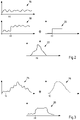
- 2 shows such a possible correlation.
- 2 shows a first course 16 of count values of a counter 8.
- the count values are shown continuously, but are preferably time-discrete values.
- the following diagrams all show continuous value curves, but can also be represented by time-discrete values.
- the course of the counter values depends on the
- this counter can, for example, supply a profile 18 of counted values. It can be seen that there is a jump in curve 18 at time t0. This jump can be caused by a subscriber 10 being switched on. The fluctuation in the counter values can be caused by power fluctuations of one subscriber 10 or other subscribers 10 arranged on the counter 8 .
- an expected value 20 can be assigned to such a control signal in this control device 12 .
- the expected value 20 which can also represent a progression of counted values, an effect on the subscriber 10, in particular the counted values at the counter 8, can be simulated by a specific control signal.
- correlation function 22 results in a maximum at time t0. This maximum at time t0 is due to the correlation of curve 18 with the expected value 20.
- a control command can not only be a switch-on and switch-off command, but can also contain a power specification for a subscriber 10, for example.
- a profile of an electrical power over a period of time can be known for a subscriber 10, so that, for example, beginning with the switch-on time t0, the profile of the electrical power and therefore the energy at the subscriber 10 can be known.
- Such a scenario is in the 3 shown.
- a profile 24 of counted values of a counter 8 at a subscriber 10 is shown.
- An expected value 26 in a control device 12 can be stored for the corresponding participant 10 .
- the expected value 26 represents the course of the power consumption and/or the energy of the participant 10.
- a corresponding participant 10 is controlled by the control device 12 and this participant 10 is connected to the counter 8, which supplies the counted values 24, then the profile of the counted values 24 is correlated with the expected value 26.
- a correlation function 28 shows a strong increase at time t0.
- the correlation between the curve 24 and the expected value 26 extends over a longer period of time, so that the correlation function 28 has a value over a longer period of time that can be above a limit value.
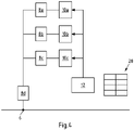
- a counter 8 can be assigned to a control device 12. Such a possible assignment can be in a system according to figs 1 , 4 , 5 , 6 take place.
- a node 6 can according to 4 connect a meter 8d to a home distribution network.
- a number of meters 8a-c can be provided within a house distribution network, each of which has a subscriber 10a-c.
- the number of participants 10a-c and their assignment to counters 8a-c and the number of counters 8a-c are shown here purely as an example. In the 4 each participant 10 has exactly one counter 8 assigned to it.
- a control device 12 is provided with which the participants 10 can be controlled. There is a communication connection between the control device 12 and the meters 8a-d, but it is unknown in the control device 12 which of the participants 10 is arranged at which meter 8a-d and therefore also unknown which power flows at which meter 8a-d the Control device 12 can affect.
- the control device 12 In the control device 12 are data sets 28 with control commands and associated expected values for individual participants 10a-c.
- control device 12 In the control device 12 counted values of the counters 8a-d are received. In normal operation, ie without a control command to one of the participants 10a-c, the counts of the counters 8a-d fluctuate and are not comprehensible for the control device 12.
- an expected value can be loaded from the data record 28 for the corresponding control command.
- the control device 12 then correlates the count values received from the counters 8a-d with this expected value.
- the counted values of counter 8a correlate most with the expected value, so that the correlation function or the absolute value of the correlation function exceeds a limit value. Such an excess can be interpreted as an indication that the control device 12 is linked to the counter 8a via the subscriber 10a. In this respect, the counter 8a can be assigned to the control device 12 .
- the control device 12 receives counted values from the counter 8d. Since the counter 8d measures the power of the subscriber 10a that has changed as a result of the control command, the course of the counter values of the counter 8d will correlate with the expected values in the control device 12 and here too a correlation function or an amount of the correlation function will exceed a limit value and an assignment of the Counter 8d to the control device 12 can take place.
- control device 12 is also linked to the counters 8b-c.
- FIG 5 shows another embodiment.
- the control devices 12a-d are not assigned to all participants 10a-d, and therefore not to all meters 8a-e.
- the control device 12a can issue a control command for the subscriber 10a in the manner described.
- the control device 12a receives counted values of the counters 8a-e.
- the change in the counter values due to the control command correlates with the corresponding expected value in the control device 12a.
- the control device 12b-d also "see" the change in the count values on the counter 8e, this change does not correlate with expected values in the control devices 12b-d, since these have not issued a corresponding control command.
- the control device 12b can issue control commands for the subscriber 10b.
- the control device 12b can be assigned to the counter 8b by correlating the count values of the counters 8a-e with the expected values.
- the control device 12b can also control the subscriber 10c. With such an actuation, a corresponding expected value in the control device 12b can be used to determine that this can be assigned to the counter 8c.
- the control commands for the participants 10b and c also result in changed counts in the counter 8e.
- the count values of this counter 8e also lead to a correlation with the expected values in the control device 12b, so that the control device 12b can also be assigned to the counter 8e.
- control device 12a and the counters 8a and e applies equally to the control device 12c and the counters 8d and e.
- the control devices 12b, c can be cascaded with the control device 12d.
- the control device 12d can thus issue control commands for the participants 10b, c and d indirectly via the control device 12b and c.
- control device 12d Based on the control commands and the resulting change in the counter values, it can be determined in the control device 12d that it can be assigned to the counters 8b, c, d and e, but not to the counter 8a.
- control device 12a receives the counted values of the counters 8a-d. By issuing control commands for the participants 8a-c, it can be determined that the control device 12a can be assigned to the meters 8a-d.
- the control device 12b can control the control device 12a and, in addition to the counted values of the counters 8a-d, also receives the counted values of the counter 8e. By issuing control commands indirectly via the control device 12a, it can be determined that the control device 12b is assigned to the counters 8a-e. The control device 12b can thus influence power flows at the connection points of the counters 8a-e via corresponding control commands.
Description
Der Gegensand betrifft ein Verfahren und ein System zur Erstellung einer Zuordnung zwischen einem Verbrauchsmengenzähler und einer Steuereinrichtung.The subject relates to a method and a system for creating an association between a consumption meter and a control device.
Sowohl im gewerblichen Bereich als auch im häuslichen Umfeld werden zunehmend Energiemanagementsysteme eingesetzt, mit denen sich Teilnehmer, welche am elektrischen Verteilnetz betrieben werden, steuern lassen. Solche Energiemanagementsystem (EMS) sind dazu eingerichtet, Schaltbefehle an die Teilnehmer zu übermitteln, um somit eine Fernsteuerbarkeit der Teilnehmer zu ermöglichen. Im häuslichen Einsatz werden EMS auch Home-Energy-Management Systeme (HEMS) genannt.Both in the commercial sector and in the domestic environment, energy management systems are increasingly being used, with which subscribers that are operated in the electrical distribution network can be controlled. Such energy management systems (EMS) are set up to transmit switching commands to the participants, in order to enable remote controllability of the participants. In domestic use, EMS are also called Home Energy Management Systems (HEMS).
Ein Teilnehmer kann eine elektrische Last und/oder ein elektrischer Verbraucher sein. Dies kann beispielsweise eine fernsteuerbare Funksteckdose sein, die von einer zentralen Steuereinrichtung im Haushalt angesteuert wird.A participant can be an electrical load and/or an electrical consumer. This can be, for example, a radio-controlled socket that can be controlled by a central control device in the household.
Steuereinrichtungen sind beispielsweise Smart-Home-Controller, Router mit Steuerungsfunktionen, Energiemanager (z.B. Kiwi Grid) oder dergleichen. Steuereinrichtungen können beispielsweise auch Steuerungen von weißer Ware (z.B. Spülmaschine, Wäschetrockner und Waschmaschine), Heizungssteuerungen oder auch Ladesteuereinrichtungen für Elektrofahrzeuge sein. Steuereinrichtungen können auch Umrichter, insbesondere Wechsel- und Gleichrichter an Erzeugungsanlagen, wie beispielsweise PV-Anlagen und Windkraftanlagen oder Energiespeichern, wie beispielsweise Batterien, sein.Control devices are, for example, smart home controllers, routers with control functions, energy managers (eg Kiwi Grid) or the like. Control devices can, for example, also be controls for white goods (eg dishwashers, tumble dryers and washing machines), heating controls or charging control devices for electric vehicles. Control devices can also be converters, in particular inverters and rectifiers in generating systems, such as PV systems and wind turbines, or energy stores, such as batteries.
Neben der Erweiterung der Funktionalität zur Steuerung von Teilnehmern wird darüber hinaus der Ausbau von Messsystemen an elektrischen Verteilnetzen vorangetrieben. Messsysteme sind beispielsweise Smart-Meter oder intelligente Messsysteme, die beispielsweise mittels Verbrauchsmengenzähler und Gateway (z.B. Smart-Meter-Gateway) oder andere Kommunikationsmöglichkeiten mit weiteren Teilnehmern, beispielsweise einer Zentrale oder auch der Steuereinrichtung kommunizieren können. Neben geeichten Messsystemen können in gleicher Weise auch ungeeichte Messsysteme (z. B. Energiekostenmessgeräte, ...) eingesetzt werden, sofern diese eine Kommunikationsmöglichkeit besitzen. Auch eine Kombination aus geeichten und ungeeichten Messsystemen ist möglich.In addition to expanding the functionality for controlling participants, the expansion of measuring systems in electrical distribution networks is being pushed ahead. Measuring systems are, for example, smart meters or intelligent measuring systems that can communicate with other participants, for example a control center or the control device, for example by means of consumption meters and gateways (e.g. smart meter gateway) or other communication options. In addition to calibrated measuring systems, uncalibrated measuring systems (e.g. energy cost measuring devices, ...) can also be used in the same way, provided they have a communication option. A combination of calibrated and non-calibrated measuring systems is also possible.
Mit Hilfe solcher Messsysteme ist es möglich, nicht nur die von einem Teilnehmer bezogenen oder zur Verfügung gestellten Energiemengen zu messen, sondern auch Energieflussrichtungen sowie zeitliche Auflösungen der jeweiligen Energieflüsse.With the help of such measuring systems, it is possible not only to measure the amounts of energy drawn or made available by a participant, but also the direction of energy flow and the temporal resolution of the respective energy flows.
Um die vorhandenen Steuereinrichtungen nutzen zu können, um definiert Einfluss auf Netzlasten innerhalb von Verteilnetzen nehmen zu können, ist eine informationstechnische Zuordnung zwischen den Steuereinrichtungen und den Messsystemen unerlässlich.In order to be able to use the existing control devices in order to be able to have a defined influence on network loads within distribution networks, an IT assignment between the control devices and the measuring systems is essential.
Derzeit erfolgt die informationstechnische Verknüpfung von energiemesstechnischen Einheiten mit den vor Ort vorhandenen flexiblen Anlagen des Haushalts über Kabel oder Funkbasis. Die Verknüpfung wird jedoch manuell durchgeführt, beispielsweise in einem sogenannten "Pairing-Prozess". Dieser Vorgang ist aufwändig und zeitintensiv. Ferner ist die einmal festgelegte Zuordnung statisch.Currently, the information technology linking of energy measurement units with the on-site flexible systems of the household takes place via cable or radio base. However, the linking is carried out manually, for example in a so-called "pairing process". This process is complex and time-consuming. Furthermore, once the assignment has been established, it is static.
Dokumente
Aus diesem Grunde lag dem Gegenstand die Aufgabe zugrunde, eine Zuordnung mittels einer Feststellung einer Beeinflussung zwischen einer Steuereinrichtung und einem an einem Versorgungsnetz betriebenen Messsystem zu vereinfachen und insbesondere zu automatisieren.For this reason, the subject matter was based on the object of simplifying and in particular automating an association by determining an influence between a control device and a measuring system operated on a supply network.
Diese Aufgabe wird durch ein Verfahren nach Anspruch 1 sowie ein System nach Anspruch 15 gelöst.This object is achieved by a method according to claim 1 and a system according to claim 15.
Die gegenständliche Lösung ermöglicht es, automatisch festzustellen, durch welche Steuereinrichtung, an einem jeweiligen Verbrauchsmengenzähler Energieflüsse beeinflusst werden können. An einem Verbrauchsmengenzähler werden Teilnehmer angeschlossen. Die Teilnehmer sind über den Verbrauchsmengenzähler in einem Versorgungsnetz betrieben.The present solution makes it possible to automatically determine which control device can be used to influence energy flows on a respective consumption meter. Subscribers are connected to a consumption meter. The participants are operated via the consumption meter in a supply network.
Teilnehmer im Sinne des Gegenstandes können Lasten, Erzeuger oder Speicher sein. Der Gegenstand lässt sich insbesondere auf elektrische Systeme anwenden, ist jedoch auch beispielsweise im Bereich der Gasverteilung und/oder Wasserverteilung einsetzbar. Nachfolgend wird das Verfahren für elektrische Systeme beschrieben, das Verfahren ist jedoch auch, wie oben beschrieben, auf andere Systeme anwendbar.Participants in the sense of the object can be loads, generators or storage. The subject can be applied in particular to electrical systems, but can also be used, for example, in the field of gas distribution and/or water distribution. In the following, the method is described for electrical systems, but the method is also applicable to other systems as described above.
Eine elektrische Last kann ein elektrischer Verbraucher sein. Ein elektrischer Erzeuger kann beispielsweise eine Erzeugungsanlage, z.B. Fotovoltaik Anlage, eine Windkraftanlage, eine Biogasanlage, eine Kraftwärmekopplungsanlage, eine Gasturbine, ein Dieselgenerator oder ein sonstiger, mechanisch betriebener Generator sein. Ein Speicher kann beispielsweise ein Pumpspeicher, ein Batteriespeicher oder dergleichen sein. All diese Teilnehmer werden an dem Versorgungsnetz betrieben und sind in der Regel über einen Verbrauchsmengenzähler unmittelbar oder mittelbar mit dem Versorgungsnetz verbunden.An electrical load can be an electrical consumer. An electrical generator can, for example, be a generating plant, e.g. a photovoltaic plant, a wind power plant, a biogas plant, a combined heat and power plant, a gas turbine, a diesel generator or another mechanically operated generator. A storage device can be, for example, a pump storage device, a battery storage device or the like. All of these subscribers are operated on the supply network and are usually connected directly or indirectly to the supply network via a consumption meter.
Eine Vielzahl von solchen Teilnehmern lässt sich fernsteuern. Hierzu steuert zumindest eine Steuereinrichtung zumindest einen jeweiligen Teilnehmer. Eine Steuereinrichtung kann beispielsweise ein Smart-Home-Controller, ein Wechselrichter, ein Gleichrichter, eine Ladesteuereinrichtung oder dergleichen sein. Zwischen zumindest einem Teilnehmer und zumindest einer Steuereinrichtung kann eine Kommunikationsverbindung, insbesondere eine Funkverbindung etabliert sein. Auch eine drahtgebundene Verbindung kann etabliert sein.A large number of such participants can be controlled remotely. For this purpose, at least one control device controls at least one respective participant. A control device can be, for example, a smart home controller, an inverter, a rectifier, a charging control device or the like. A communication connection, in particular a radio connection, can be established between at least one participant and at least one control device. A wired connection can also be established.
Mit Hilfe der Steuereinrichtung lässt sich ein Teilnehmer ein- und ausschalten bzw. der Energiefluss (gegebenenfalls stufenlos) beeinflussen. Ferner ist es möglich, dass eine Steuereinrichtung einen Betriebsmodus eines Teilnehmers einstellt.With the help of the control device, a participant can be switched on and off or the energy flow can be influenced (possibly steplessly). It is also possible for a control device to set an operating mode for a subscriber.
Um nun zu ermöglichen, dass über die Steuereinrichtung gezielt Eingriff in Energieflüsse entlang des Versorgungsnetzes genommen wird, ist es notwendig zu wissen, über welche Steuereinrichtung ein Energiefluss an welchen Verbrauchsmengenzähler einstellbar ist. Daher soll eine informationstechnische Verknüpfung, mithin eine Zuordnung zwischen einem Verbrauchsmengenzähler und einer Steuereinrichtung etabliert werden. Diese Zuordnung soll automatisiert erfolgen.In order to make it possible for the control device to specifically intervene in energy flows along the supply network, it is necessary to know which control device can be used to set an energy flow to which consumption meter. Therefore, an information technology link, and therefore an association between a consumption meter and a control device should be established. This assignment should be automated.
Es wird daher vorgeschlagen, dass von der Steuereinrichtung an den zumindest einen Teilnehmer ein Steuerbefehl ausgesendet wird. In Reaktion auf diesen Steuerbefehl wird der Teilnehmer mit höchster Wahrscheinlichkeit sein Verhalten ändern und insbesondere seine bezogene oder abgegebene Leistung verändern.It is therefore proposed that a control command be sent from the control device to the at least one participant. In response to this control command, the subscriber will most likely change his behavior and, in particular, change the power he draws or delivers.
Empfängt der Teilnehmer einen Steuerbefehl, so verändert sich sein elektrisches Verhalten. Diese Veränderung des elektrischen Verhaltens führt dazu, dass sich in der elektrischen Verbindung zwischen dem Versorgungsnetz und dem Teilnehmer ein elektrischer Parameter (Strom, Spannung, Phasenlagen, Energieflussrichtung, etc.) verändert. Da der Teilnehmer über einen Verbrauchsmengenzähler mit dem Versorgungsnetz verbunden ist, kann eine solche Veränderung an dem Verbrauchsmengenzähler detektiert werden.If the participant receives a control command, its electrical behavior changes. This change in the electrical behavior means that an electrical parameter (current, voltage, phase positions, direction of energy flow, etc.) changes in the electrical connection between the supply network and the subscriber. Since the subscriber is connected to the supply network via a consumption meter, such a change can be detected on the consumption meter.
Es wird vorgeschlagen, dass Zählwerte des Verbrauchsmengenzählers in der Steuereinrichtung empfangen werden. Der Verbrauchsmengenzähler, beispielsweise ein Smart-Meter oder ein intelligentes Messsystem (Smart-Meter mit Smart-Meter-Gateway oder Multi-Utility-Communication Gateway) erfasst über Zählwerte elektrische Parameter zwischen dem Versorgungsnetz und dem Teilnehmer. Die Zählwerte können beispielsweise eine Spannung, ein Strom, eine Stromflussrichtung, eine elektrische Leistung, eine Phasenlage, eine Leistungsflussrichtung und/oder eine Energie über ein Zeitintervall von beispielsweise wenigen Sekunden bis einige Minuten sein.It is proposed that counted values of the consumption quantity counter are received in the control device. The consumption meter, for example a smart meter or an intelligent measuring system (smart meter with smart meter gateway or multi-utility communication gateway) records electrical parameters between the supply network and the subscriber via count values. The counter values can, for example, be a voltage, a current, a direction of current flow, be an electrical power, a phase position, a direction of power flow and/or energy over a time interval of, for example, a few seconds to a few minutes.
In der Steuereinrichtung ist ein Prozess etabliert, der Kenntnis darüber hat, welche Steuerbefehle zu welchen Veränderungen an dem Teilnehmer führen. Insbesondere kann eine Kenntnis darüber existieren, wie sich das elektrische Verhalten eines Teilnehmers abhängig von einem Steuerbefehl verändert sollte. Es können also Sollwerte für elektrische Parameter definiert sein, die als Erwartungswerte gespeichert sind. Wenn in Reaktion auf einen Steuerbefehl der Teilnehmer sein Verhalten ändert, so hat dies Auswirkung auf die Zählwerte des Verbrauchmengenzählers. In der Steuereinrichtung sind zugeordnet zu einem Steuerbefehl Erwartungswerte für die Zählwerte des Verbrauchsmengenzählers hinterlegt.A process is established in the control device which has knowledge of which control commands lead to which changes in the subscriber. In particular, there may be knowledge about how the electrical behavior of a participant should change depending on a control command. Target values for electrical parameters can therefore be defined, which are stored as expected values. If the participant changes his behavior in response to a control command, this has an effect on the counted values of the consumption meter. Expected values for the metered values of the consumption meter are stored in the control device, assigned to a control command.
Als einfachstes Beispiel kann z.B. ein Steuerbefehl "An" betrachtet werden. Für diesen Steuerbefehl "An" kann als Erwartungswert eine Sprungfunktion angenommen werden. Das heißt, dass in Reaktion auf den Steuerbefehl "An" an dem Verbrauchsmengenzähler, der mit dem Teilnehmer verbunden ist, ein Sprung der elektrischen Leistung feststellbar sein müsste, und mithin der entsprechenden Zählwerte.A control command "On" can be considered as the simplest example. A step function can be assumed as the expected value for this "On" control command. This means that in response to the "On" control command on the consumption meter connected to the subscriber, a jump in the electrical power should be detectable, and therefore in the corresponding metered values.
Um nun festzustellen, an welchem Verbrauchsmengenzähler ein Steuerbefehl der Steuereinrichtung eine Auswirkung hat, wird vorgeschlagen, dass die empfangenen Zählwerte mit von den Steuerbefehlen abhängigen, in der Steuereinrichtung gespeicherten Erwartungswerten korreliert werden. Hierbei eignet sich insbesondere zeitliche Korrelation zwischen den Erwartungswerten und den Zählwerten, bevorzugt über einen Betrachtungszeitraum von beispielsweise wenigen Sekunden bis wenigen Minuten. Eine Korrelation kann beispielsweise eine Kreuzkorrelation sein. Insbesondere eine numerische Kreuzkorrelation, beispielsweise mittels Sum of Square Difference (SSD) oder dergleichen ist möglich.In order to now determine on which consumption meter a control command from the control device has an effect, it is proposed that the count values received be correlated with expected values that are dependent on the control commands and are stored in the control device. A temporal correlation between the expected values and the counted values is particularly suitable here, preferably over an observation period of, for example, a few seconds to a few minutes. A correlation can be a cross-correlation, for example. In particular, a numerical cross-correlation, for example using Sum of Square Difference (SSD) or the like, is possible.
In der Steuereinrichtung werden Zählwerte bevorzugt von einer Mehrzahl von Verbrauchsmengenzählern empfangen. Um festzustellen, welchem Verbrauchsmengenzähler eine Steuereinrichtung zugeordnet ist, wird die Korrelation ausgewertet. Korrelieren die Zählwerte mit den Erwartungswerten, so bedeutet dies, dass der Steuerbefehl mit hoher Wahrscheinlichkeit an einem Teilnehmer durchgeführt wurde, dessen Verbrauchsmengenzähler der Steuereinrichtung zugeordnet werden kann. Daher erfolgt gegenständlich das Zuordnen des Verbrauchsmengenzählers zu der Steuereinrichtung abhängig von der Korrelation. Hierbei ist es insbesondere möglich, dass ein Betrag einer Kreuzkorrelationsfunktion ausgewertet wird und beim Überschreiten eines Grenzwertes die Zuordnung erfolgt.In the control device, counted values are preferably received from a plurality of consumption quantity counters. The correlation is evaluated in order to determine which consumption meter is assigned to a control device. If the counted values correlate with the expected values, this means that the control command was carried out with a high degree of probability at a subscriber whose consumption meter can be assigned to the control device. Therefore, in the present case, the consumption quantity meter is assigned to the control device as a function of the correlation. In this case, it is possible in particular for an absolute value of a cross-correlation function to be evaluated and for the allocation to take place when a limit value is exceeded.
Es versteht sich, dass eine solche Zuordnung statistisch basiert ist. Zur Erhöhung der Wahrscheinlichkeit, dass eine so durchgeführte Zuordnung korrekt ist, wird es sinnvoll sein, die Korrelation über eine Vielzahl von Steuerbefehlen und/oder Zeitfenstern, insbesondere mit Hilfe eines gleitenden Zeitfensters durchzuführen und stetig neu zu evaluieren, welche Zuordnung am wahrscheinlichsten ist.It goes without saying that such an assignment is statistically based. In order to increase the probability that an assignment carried out in this way is correct, it will make sense to carry out the correlation over a large number of control commands and/or time windows, in particular with the aid of a sliding time window, and to continuously re-evaluate which assignment is the most likely.
Das gegenständliche Verfahren ermöglicht somit, festzustellen, welcher Verbrauchsmengenzähler über welche Steuereinrichtung beeinflussbar ist, insbesondere an welchem Verbrauchsmengenzähler eine Steuereinrichtung einen elektrischen Parameter beeinflussen kann. Diese Zuordnung gemäß des Gegenstandes kommt ohne einen manuellen Eingriff, insbesondere die Eingabe von Kennwörtern oder eine manuelle Verdrahtung oder funktechnische Kopplung aus. Es ist nicht notwendig, manuell einen Pairing-Prozess zwischen dem Verbrauchsmengenzähler und der Steuereinrichtung herzustellen.The present method thus makes it possible to determine which consumption meter can be influenced via which control device, in particular on which consumption meter a control device can influence an electrical parameter. This assignment according to the object does not require manual intervention, in particular the input of passwords or manual wiring or radio-technical coupling. It is not necessary to manually set up a pairing process between the consumption meter and the control device.
Das gegenständliche Verfahren setzt voraus, dass eine kommunikationstechnische Verbindung zwischen dem Verbrauchsmengenzähler und der Steuereinrichtung, mittelbar oder unmittelbar besteht. Eine solche Verbindung kann insbesondere funktechnisch sein und der Verbrauchsmengenzähler kann beispielsweise über eine Kommunikationseinheit seine Zählwerte zur Verfügung stellen. In einer Umgebung mit einer Mehrzahl an Verbrauchsmengenzählern können diese jeweils einzeln ihre Zählwerte insbesondere über eine Luftschnittstelle zur Verfügung stellen. Die Steuereinrichtung kann diese Zählwerte insbesondere über die Luftschnittstelle empfangen, insbesondere unmittelbar oder mittelbar über Umwege, beispielsweise von einer räumlich entfernten Zentrale oder dergleichen.The present method presupposes that there is a direct or indirect communication link between the consumption meter and the control device. Such a connection can in particular be wireless and the consumption meter can, for example, via a Communication unit make its counts available. In an environment with a plurality of consumption meters, these can each make their counted values available individually, in particular via an air interface. The control device can receive these counter values in particular via the air interface, in particular directly or indirectly via detours, for example from a remote control center or the like.
Die Verbrauchsmengenzähler teilen in Abständen, insbesondere regelmäßig beispielsweise Energiemesswerte oder sonstige elektrische Parameter, nachfolgend auch Zählwerte genannt, über eine Schnittstelle mit. Eine solche Schnittstelle kann beispielsweise RS232, Wireless M-BUS, S-NULL, Impulsausgang, Powerline, Ethernet, Bluetooth oder dergleichen sein. Die Steuereinrichtung kann die Zählwerte entweder über dieselbe Schnittstelle empfangen, über die sie ausgesendet wurden oder mittelbar über Umwege, beispielsweise von einer zwischengeschalteten, räumlich entfernten Zentrale oder dergleichen. Es ist nicht notwendig, dass eine unmittelbare Verbindung zwischen der Steuereinrichtung und dem Verbrauchsmengenzähler gebildet ist. Die Zählwerte können von dem Verbrauchsmengenzähler im Broadcast oder im Multicast ausgesendet werden und Zählwerte eines Verbrauchsmengenzählers können von einer Mehrzahl von Steuereinrichtungen empfangen werden.The consumption meters communicate at intervals, in particular regularly, for example measured energy values or other electrical parameters, also referred to below as count values, via an interface. Such an interface can be, for example, RS232, Wireless M-BUS, S-NULL, pulse output, Powerline, Ethernet, Bluetooth or the like. The control device can receive the counted values either via the same interface via which they were sent out or indirectly via detours, for example from an intermediate, spatially distant control center or the like. It is not necessary for a direct connection to be formed between the control device and the consumption meter. The metered values can be broadcast or multicast by the consumption meter, and metered values of a consumption meter can be received by a plurality of control devices.
Gemäß einem Ausführungsbeispiel wird vorgeschlagen, dass die empfangenen Zählwerte mit den Erwartungswerten fortlaufend korrigiert werden und dass Zuordnungen dynamisch abhängig von aktuellen und/oder kumulierten Korrelationen verändert werden. So ist es beispielsweise möglich, den Betrag der Korrelationsfunktion zu normalisieren. Normalisierte Korrelationswerte können dann miteinander verglichen werden. Sind mehrere Verbrauchsmengenzähler vorhanden, so kann für jeden dieser Verbrauchsmengenzähler in der Steuereinrichtung ein Wert der Korrelation bestimmt werden. Ist dieser Wert normalisiert, so kann ein Vergleich der Werte erfolgen.According to one exemplary embodiment, it is proposed that the count values received be continuously corrected with the expected values and that assignments be changed dynamically as a function of current and/or cumulative correlations. For example, it is possible to normalize the absolute value of the correlation function. Normalized correlation values can then be compared with one another. If there are several consumption counters, a correlation value can be determined for each of these consumption counters in the control device. If this value is normalized, the values can be compared.
Auch ist es möglich, für jeweils einen der Verbrauchsmengenzähler den Korrelationswert zu bestimmen und zu überprüfen, ob dieser Wert einen Grenzwert überschreitet. In diesem Fall kann eine Zuordnung zwischen dem Verbrauchsmengenzähler und der Steuereinrichtung erfolgen. Da ein Teilnehmer über zwei oder mehr Verbrauchsmengenzähler an einem Versorgungsnetz betrieben sein kann, ist es durchaus denkbar, dass die Steuereinrichtung über einen Steuerbefehl eine Veränderung an Zählwerten an einer Mehrzahl an Verbrauchsmengenzählern bewirkt, wobei diese Änderungen zu einer Erhöhung des Betrags der Korrelation führen.It is also possible to determine the correlation value for one of the consumption quantity counters and to check whether this value exceeds a limit value. In this case, there can be an association between the consumption meter and the control device. Since a subscriber can be operated via two or more consumption meters on a supply network, it is entirely conceivable that the control device uses a control command to change the metered values on a plurality of consumption meters, with these changes leading to an increase in the amount of the correlation.
Auch ist es möglich, dass ein Betrag einer Korrelationsfunktion abhängig von der Zeitspanne seit dem Steuerbefehl reduziert wird. Somit werden erfasste Korrelationen zeitlich gewichtet. So gewichtete Korrelationsbeträge können kumuliert werden und eine Zuordnung kann abhängig von einer so gebildeten Summe von Korrelationsbeträgen sein.It is also possible that an amount of a correlation function is reduced depending on the time span since the control command. Thus detected correlations are time-weighted. Correlation amounts weighted in this way can be accumulated and an assignment can be dependent on a sum of correlation amounts formed in this way.
Durch die fortlaufende Überprüfung der Korrelation kann in einem sich dynamisch ändernden Umfeld stets eine hochverlässige Zuordnung zwischen Verbrauchsmengenzähler und Steuereinrichtung erfolgen. Es ist durchaus denkbar, dass ein Teilnehmer mobil betrieben wird, so dass er zu einem ersten Zeitpunkt an einem ersten Verbrauchsmengenzähler angeschlossen ist und zu einem zweiten Zeitpunkt an einem zweiten Verbrauchsmengenzähler. Erfolgt ein Steuerbefehl für einen solchen Teilnehmer, führt dies in dem ersten Zeitpunkt zu einer Veränderung der Zählwerte des ersten Verbrauchsmengenzählers und in dem zweiten Zeitpunkt zu einer Veränderung der Zählwerte des zweiten Verbrauchsmengenzählers. Die Steuereinrichtung müsste in dem ersten Zeitpunkt mit dem ersten Verbrauchsmengenzähler zugeordnet werden und in dem zweiten Zeitpunkt mit dem zweiten Verbrauchsmengenzähler. Solche Veränderungen lassen sich dynamisch abbilden, in dem die Zuordnung dynamisch abhängig von aktuellen Korrelationen verändert wird. Auch lassen sich im Sinne eines selbstlernenden Algorithmus aktuelle Korrelationen mit Werten aus der Vergangenheit vergleichen oder auf dieser Basis Prognosen für die gegebenenfalls zeitlich eingeschränkte Korrelation in der Zukunft ermitteln. Somit können zeitliche Intervalle festgelegt werden, in denen Korrelationen beobachtet werden. Korrelationen außerhalb der Intervalle können bei der dynamischen Zuordnung unberücksichtigt bleiben.By continuously checking the correlation, a highly reliable association can always be made between the consumption meter and the control device in a dynamically changing environment. It is entirely conceivable for a subscriber to be operated on a mobile basis, so that he is connected to a first consumption meter at a first point in time and to a second consumption meter at a second point in time. If a control command is issued for such a subscriber, this leads to a change in the counted values of the first consumption quantity counter at the first point in time and to a change in the counted values of the second consumption quantity counter at the second point in time. The control device would have to be assigned to the first consumption meter at the first point in time and to the second consumption meter at the second point in time. Such changes can be mapped dynamically by changing the assignment dynamically depending on current correlations. In the sense of a self-learning algorithm, current correlations can also be compared with values from the past or on this basis Determine forecasts for the possibly time-limited correlation in the future. In this way, time intervals can be defined in which correlations are observed. Correlations outside the intervals can be ignored in the dynamic assignment.
Gemäß einem Ausführungsbeispiel wird vorgeschlagen, dass die Erwartungswerte abhängig von Sendezeitpunkten der Steuerbefehle und/oder Informationen zu einer Leistung des Teilnehmers und/oder einem Betriebsverhalten des Teilnehmers sind. Wird ein "An"-Befehl ausgesendet, so ist ab diesem Zeitpunkt mit einem Sprung in den Zählwerten an dem verknüpften Verbrauchsmengenzähler zu rechnen. Somit ist ein Erwartungswert abhängig von einem Sendezeitpunkt. Auch ein "Aus"-Befehl ist mit einem Erwartungswert einer inversen Sprungfunktion verknüpft und zum Zeitpunkt des Sendens des "Aus"-Steuerbefehls sollte die Zählwerte eines zugeordneten Verbrauchsmengenzählers einen solchen inversen Sprung aufweisen.According to one exemplary embodiment, it is proposed that the expected values be dependent on the transmission times of the control commands and/or information on the subscriber's performance and/or the subscriber's operating behavior. If an "On" command is sent, a jump in the metered values on the linked consumption meter is to be expected from this point in time. An expected value is therefore dependent on a transmission time. An “off” command is also linked to an expected value of an inverse step function, and at the time the “off” control command is sent, the counted values of an associated consumption quantity counter should have such an inverse step.
Auch eine Leistung eines Teilnehmers kann relevant sein. Die Leistung des Teilnehmers kann sich in dem Betrag des Zählwertes niederschlagen. Auch ein solcher Betrag kann in einem Erwartungswert hinterlegt sein.A performance by a participant can also be relevant. The participant's performance may be reflected in the amount of the count. Such an amount can also be stored in an expected value.
Auch ein Betriebsverhalten eines Teilnehmers kann relevant sein. Ist beispielsweise bekannt, dass ein Teilnehmer ein bestimmtes Leistungsprofil über eine gewisse Zeit hat, kann dieses Profil in den Erwartungswerten hinterlegt werden. Ein Abgleich der Zählwerte mit solchen Erwartungswerten führt mit einer hohen Genauigkeit zu einer korrekten Zuordnung zwischen Verbrauchsmengenzähler und Steuereinrichtung.A subscriber's operating behavior can also be relevant. For example, if it is known that a participant has a specific performance profile over a certain period of time, this profile can be stored in the expected values. A comparison of the counted values with such expected values leads to a correct association between consumption meter and control device with a high level of accuracy.
Gemäß einem Ausführungsbeispiel wird vorgeschlagen, dass die Erwartungswerte eine zeitliche Reihe von Erwartungswerten umfassen. Insbesondere können diskrete Erwartungswerte in Intervallen, beispielsweise in Abständen von wenigen Sekunden eine zeitliche Reihe bilden. Das gleiche gilt für Zählwerte, die ebenfalls eine zeitliche Reihe von Messwerten umfassen können. Solche Messwerte können insbesondere elektrische Parameter, wie beispielsweise Energiemengen, Leistungsmengen, Strommesswerte oder Spannungsmesswerte oder dergleichen umfassen.According to one embodiment, it is proposed that the expected values include a time series of expected values. In particular, discrete expected values can form a time series at intervals, for example at intervals of a few seconds. The same applies to counter values, which can also include a series of measured values over time. Such measured values can in particular include electrical parameters such as amounts of energy, amounts of power, measured current values or measured voltage values or the like.
Gemäß einem Ausführungsbeispiel wird vorgeschlagen, dass die Steuerbefehle Zu- und/oder Abschaltbefehle für den Teilnehmer umfassen und/oder dass die Steuerbefehle zumindest eine Leistungsvorgabe für den Teilnehmer umfassen. Ist in einem Steuerbefehl eine Leistungsvorgabe enthalten, so kann dieser Leistungswert insbesondere den Betrag eines Erwartungswertes beeinflussen.According to one exemplary embodiment, it is proposed that the control commands include connection and/or disconnection commands for the subscriber and/or that the control commands include at least one power specification for the subscriber. If a power specification is contained in a control command, this power value can in particular influence the amount of an expected value.
Gemäß einem Ausführungsbeispiel wird vorgeschlagen, dass zumindest abhängig von der Zuordnung eine von der Steuereinrichtung an den Teilnehmer an jeweils einem Verbrauchsmengenzähler beinflussbare Leistung bestimmt wird. Durch die Zuordnung kann festgestellt werden, welchen Verbrauchsmengenzähler eine Steuereinrichtung zugeordnet ist und/oder welches elektrische Verhalten an welchem Verbrauchsmengenzähler durch eine bestimmte Steuereinrichtung beeinflusst werden kann. Ist beispielsweise bekannt, welche Summe von Teilnehmern über eine bestimmte Steuereinrichtung an eine bestimmten Verbrauchsmengenzähler beeinflusst werden kann, kann bestimmt werden, wie hoch beispielsweise die Leistung ist, die eine Steuereinrichtung an dem zugeordneten Verbrauchsmengenzähler beeinflussen kann. Diese Information kann relevant sein für eine Netzsteuerung und insbesondere eine Netzstabilisierung.According to one exemplary embodiment, it is proposed that a power that can be influenced by the control device to the subscriber at a respective consumption meter is determined at least as a function of the assignment. The assignment can be used to determine which consumption meter is assigned a control device and/or which electrical behavior at which consumption meter can be influenced by a specific control device. For example, if it is known what sum of participants can be influenced via a specific control device on a specific consumption meter, it can be determined how high the power is, for example, which a control device can influence on the associated consumption meter. This information can be relevant for network control and, in particular, network stabilization.
Zur Netzführung kann es sinnvoll sein, die Steuereinrichtungen extern anzusteuern, um so Leistungsflüsse in dem Versorgungsnetz an bestimmten Punkten zu beeinflussen, insbesondere an den Verknüpfungspunkten der Verbrauchsmengenzähler mit dem Versorgungsnetz. Ist bekannt, welche Steuereinrichtung welchem Verbrauchsmengenzähler zugeordnet ist, kann durch gezielte Ansteuerung der jeweiligen Steuereinrichtung auch der Leistungsfluss an dem jeweilig Verknüpfungspunkt des zugeordneten Verbrauchsmengenzählers beeinflusst werden.For network management, it can be useful to control the control devices externally in order to influence power flows in the supply network at specific points, in particular at the connection points of the consumption meter with the supply network. If it is known which control device is assigned to which consumption meter, the power flow at the respective connection point of the assigned consumption meter can also be influenced by targeted activation of the respective control device.
Gemäß einem Ausführungsbeispiel wird vorgeschlagen, dass zumindest einem Verbrauchsmengenzähler ein Verknüpfungspunkt zwischen einem Hausverteilnetz und einem öffentlichen Versorgungsnetz zugeordnet ist und dass der Steuereinrichtung abhängig von der Zuordnung eine an dem Verknüpfungspunkt beeinflussbare Leistung zugeordnet wird. Diese beeinflussbare Leistung kann beispielsweise von einer räumlich entfernten Zentrale der Steuereinrichtung mitgeteilt werden. Über die externe Zentrale kann so eine Netzführung erfolgen, in dem eine Leistungsflussveränderung an dem Verknüpfungspunkt über die Steuereinrichtung eingestellt werden kann und somit Leistungsflüsse in dem öffentlichen Versorgungsnetz beeinflusst werden können.According to one exemplary embodiment, it is proposed that at least one consumption meter is assigned a node between a house distribution network and a public supply network and that the control device is assigned a power that can be influenced at the node depending on the assignment. This power, which can be influenced, can be communicated to the control device, for example, by a spatially distant control center. Network management can be carried out via the external control center in that a power flow change can be set at the node via the control device and power flows in the public supply network can thus be influenced.
Gemäß einem Ausführungsbeispiel wird vorgeschlagen, dass die Steuereinrichtung einen Vorgabewert für eine Veränderung einer Leistung an einem Verknüpfungspunkt empfängt und abhängig von dem Vorgabewert zumindest einen Teilnehmer ansteuert. Für den Fall der aktiven Netzbeeinflussung kann von einem externen Steuerrechner eine Vorgabe für eine Veränderung einer Leistung an einem bestimmten Verknüpfungspunkt an die Steuereinrichtung übermittelt werden. In der Steuereinrichtung kann dann abhängig von der Zuordnung zu dem jeweiligen Verbrauchsmengenzähler eine entsprechende Anzahl an Steuerbefehlen abgesetzt werden, um zumindest einen Teilnehmer anzusteuern und den Vorgabewert für die veränderte Leistung an dem Verknüpfungspunkt einzuhalten.According to one exemplary embodiment, it is proposed that the control device receives a default value for a change in power at a node and controls at least one subscriber as a function of the default value. In the event of active network influencing, a specification for a change in power at a specific connection point can be transmitted to the control device from an external control computer. Depending on the assignment to the respective consumption meter, a corresponding number of control commands can then be issued in the control device in order to control at least one subscriber and to comply with the default value for the changed power at the node.
Gemäß einem Ausführungsbeispiel wird vorgeschlagen, dass zumindest drei Steuereinrichtungen kaskadiert verschaltet sind, so dass zumindest eine erste übergeordnete Steuereinrichtung zumindest zwei voneinander unabhängige, nachgeordnete Steuereinrichtungen ansteuert und dass die Zuordnung zu zumindest einer der nachgeordneten Steuereinrichtungen und zumindest einer der übergeordneten Steuereinrichtungen erfolgt. In einem solchen Fall kann beispielsweise durch eine übergeordnete Steuereinrichtung eine nachgeordnete Steuereinrichtung beeinflusst werden. Die übergeordnete Steuereinrichtung kann zumindest zwei nachgeordnete Steuereinrichtungen beeinflussen. Jede dieser nachgeordneten Steuereinrichtungen kann jeweils zumindest einen Teilnehmer beeinflussen. Die beeinflussten Teilnehmer können über verschiedene Verbrauchsmengenzähler mit dem Versorgungsnetz verknüpft sein. Wird von einer nachgeordneten Steuereinrichtung ein Steuerbefehl abgesetzt, so führt dies zu einer Veränderung der Zählwerte an dem zugeordneten Verbrauchsmengenzähler. Die Korrelation des Steuerbefehls zu der Veränderung des Zählwertes kann dann in den nachgeordneten Steuereinrichtungen als auch der übergeordneten Steuereinrichtung detektiert werden und sowohl die übergeordnete als auch die nachgeordnete Steuereinrichtung kann dem jeweiligen Verbrauchsmengenzähler zugeordnet werden.According to one exemplary embodiment, it is proposed that at least three control devices are cascaded, so that at least a first higher-level control device controls at least two independent, lower-level control devices and that at least one of the lower-level control devices and at least one of the higher-level control devices are assigned. In such a case, a downstream control device can be influenced, for example, by a higher-level control device. The higher-level control device can influence at least two downstream control devices. Any of these subordinate control devices can each influence at least one participant. The participants affected can be linked to the supply network via various consumption meters. If a control command is issued by a downstream control device, this leads to a change in the counted values on the assigned consumption quantity counter. The correlation of the control command to the change in the counter value can then be detected in the downstream control devices and the higher-level control device, and both the higher-level and the lower-level control device can be assigned to the respective consumption meter.
Gemäß einem Ausführungsbeispiel wird vorgeschlagen, dass der Verbrauchsmengenzähler einen Energiemengenzähler, insbesondere einen elektrischen Energiemengenzähler, insbesondere ein Smart-Meter oder ein intelligentes Messsystem ist.According to one exemplary embodiment, it is proposed that the consumption meter is an energy meter, in particular an electrical energy meter, in particular a smart meter or an intelligent measuring system.
Auch wird vorgeschlagen, wie oben bereits beschrieben, dass der Verbrauchsmengenzähler in Kommunikationsverbindung mit zumindest einer Steuereinrichtung ist. Diese Kommunikationsverbindung kann unmittelbar oder mittelbar über einen beispielsweise zwischengeschalteten zentralen Server sein. Die Kommunikationsverbindung erfolgt insbesondere über die Luftschnittstelle.As already described above, it is also proposed that the consumption meter be in communication with at least one control device. This communication connection can be direct or indirect, for example via a central server connected in between. The communication connection takes place in particular via the air interface.
Gemäß einem Ausführungsbeispiel wird vorgeschlagen, dass zumindest ein Verbrauchsmengenzähler im Hausverteilnetz angeordnet ist und/oder dass zumindest ein Verbrauchsmengenzähler in einem öffentlichen Versorgungsnetz angeordnet ist. Die Verbrauchsmengenzähler können somit sowohl in einer Hausunterverteilung als auch unmittelbar in oder an dem öffentlichen Versorgungsnetz angeordnet sein.According to one exemplary embodiment, it is proposed that at least one consumption meter be arranged in the house distribution network and/or that at least one consumption meter be arranged in a public supply network. The consumption meters can thus be arranged both in a house sub-distribution and directly in or on the public supply network.
Gemäß einem Ausführungsbeispiel wird vorgeschlagen, dass der Teilnehmer ein Verbraucher, insbesondere ein elektrischer Verbraucher ist. Auch wird vorgeschlagen, dass der Teilnehmer ein Erzeuger, insbesondere ein elektrischer Erzeuger, beispielsweise eine Fotovoltaik Anlage, einen Windkraftanlagen, eine KWK-Anlage, eine Biomasseanlage oder dergleichen ist. Auch wird vorgeschlagen, dass der Teilnehmer ein Speicher, insbesondere ein elektrischer Speicher ist. Das gegenständlich Verfahren lässt sich insbesondere auch in einer gemischten Umgebung einsetzen, in dem verschiedene Teilnehmer, beispielsweise Lasten (Verbraucher, Erzeuger und/oder Teilnehmer) gleichzeitig betrieben werden.According to one exemplary embodiment, it is proposed that the subscriber is a consumer, in particular an electrical consumer. It is also proposed that the participant is a producer, in particular an electrical producer, For example, a photovoltaic system, a wind turbine, a CHP system, a biomass plant or the like. It is also proposed that the subscriber is a memory, in particular an electrical memory. The method in question can also be used in particular in a mixed environment in which different participants, for example loads (consumers, generators and/or participants) are operated at the same time.
Ein weiterer Aspekt ist ein System nach Anspruch 15. Dieses System umfasst eine Steuereinrichtung, zumindest einen Verbrauchsmengenzähler und einen Teilnehmer in einem Versorgungsnetz, wobei die Steuereinrichtung in Wirkverbindung mit dem Teilnehmer ist und wobei der Verbrauchsmengenzähler in Kommunikationsverbindung mit der Steuereinrichtung ist.Another aspect is a system according to claim 15. This system comprises a control device, at least one consumption meter and a subscriber in a supply network, the control device being operatively connected to the subscriber and the consumption meter being in communication with the control device.
Der Gegenstand betrifft auch ein Computerprogramm, das Programmanweisungen umfasst, die einen Prozessor zur Ausführung und/oder Steuerung des hier beschriebenen Verfahrens veranlassen, wenn das Computerprogramm auf dem Prozessor läuft.The subject also relates to a computer program that includes program instructions that cause a processor to execute and/or control the method described here when the computer program runs on the processor.
Unter einem Prozessor sollen in dieser Spezifikation unter anderem Kontrolleinheiten, Mikroprozessoren, Mikrokontrolleinheiten wie Mikrocontroller, digitale Signalprozessoren (DSP), Anwendungsspezifische Integrierte Schaltungen (ASICs) oder Field Programmable Gate Arrays (FPGAs) verstanden werden. Dabei können entweder alle Schritte des Verfahrens gesteuert werden, oder alle Schritte des Verfahrens ausgeführt werden, oder ein oder mehrere Schritte gesteuert und ein oder mehrere Schritte ausgeführt werden. Das Computerprogramm kann beispielsweise über ein Netzwerk wie das Internet, ein Telefon- oder Mobilfunknetz und/oder ein lokales Netzwerk verteilbar sein. Das Computerprogramm kann zumindest teilweise Software und/oder Firmware eines Prozessors sein. Es kann gleichermaßen zumindest teilweise als Hardware implementiert sein. Das Computerprogramm kann beispielsweise auf einem computerlesbaren Speichermedium gespeichert sein, z.B. einem magnetischen, elektrischen, elektro-magnetischen, optischen und/oder andersartigen Speichermedium. Das Speichermedium kann beispielsweise Teil des Prozessors sein, beispielsweise ein (nicht-flüchtiger oder flüchtiger) Programmspeicher des Prozessors oder ein Teil davon. Das Speichermedium ist beispielsweise gegenständlich, also greifbar, und/oder nicht-transitorisch. Das Computerprogramm wird bevorzugt auf einem Prozessor in der Steuereinrichtung ausgeführt.In this specification, a processor should be understood to mean, inter alia, control units, microprocessors, microcontrol units such as microcontrollers, digital signal processors (DSP), application-specific integrated circuits (ASICs) or field programmable gate arrays (FPGAs). In this case, either all steps of the method can be controlled, or all steps of the method can be carried out, or one or more steps can be controlled and one or more steps can be carried out. The computer program can be distributed, for example, via a network such as the Internet, a telephone or mobile network and/or a local area network. The computer program can be at least partially software and/or firmware of a processor. It can equally be implemented at least partially in hardware. The computer program can be stored, for example, on a computer-readable storage medium, for example a magnetic, electrical, electromagnetic, optical and/or different storage medium. The storage medium can, for example, be part of the processor, for example a (non-volatile or volatile) program memory of the processor or a part thereof. The storage medium is, for example, physical, ie tangible, and/or non-transitory. The computer program is preferably executed on a processor in the control device.
Nachfolgend wird der Gegenstand anhand einer Ausführungsbeispiele zeigenden Zeichnung näher erläutert:
- Fig. 1
- ein System zur Steuerung von Leistungsflüssen in einem Netz;
- Fig. 2
- eine mögliche Korrelation empfangener Zählwerte mit Erwartungswerten;
- Fig. 3
- eine weitere mögliche Korrelation zwischen empfangenen Zählwerten und Erwartungswerten;
- Fig. 4
- eine Anordnung mit Steuereinrichtung, Teilnehmer und Zähleinrichtung gemäß einem Ausführungsbeispiel;
- Fig. 5
- eine weitere Anordnung von Steuereinrichtung, Teilnehmer und Zähleinrichtung gemäß einem weiteren Ausführungsbeispiel;
- Fig. 6
- eine weitere Anordnung von Steuereinrichtung, Teilnehmer und Zähleinrichtung gemäß einem Ausführungsbeispiel.
- 1
- a system for controlling power flows in a network;
- 2
- a possible correlation of received count values with expected values;
- 3
- another possible correlation between received count values and expected values;
- 4
- an arrangement with control device, participant and counting device according to an embodiment;
- figure 5
- a further arrangement of control device, participant and counting device according to a further exemplary embodiment;
- 6
- a further arrangement of control device, participant and counting device according to an embodiment.
Ein Energieversorgungsnetz kann beispielsweise einen niederspannungsseitigen Versorgungsstrang 2, der über Trafo 4 mit einem Mittelspannungsnetz verbunden ist, aufweisen. An dem Versorgungsstrang 2 können Verknüpfungspunkte 6 vorgesehen sein, über die Hausverteilnetze mit dem Versorgungsstrang 2 verbunden sind.An energy supply network can, for example, have a low-voltage
In den jeweiligen Hausverteilnetzen, die natürlich auch industrielle Anlagen sein können, können ein oder mehrere Zähler 8 angeordnet sein, die elektrische Parameter wie eine elektrische Leistung und/oder eine Leistungsflussrichtung und/oder einen Strom und/oder eine Stromrichtung und/oder eine Spannung und/oder eine Phasenlage und/oder eine elektrische Energiemenge messen können. Die Zähler 8 sind Verbrauchsmengenzähler und erfassen elektrische Parameter, insbesondere eine elektrische Energie. Die Zähler 8 sind dabei bevorzugt Smart Meter oder intelligente Messsysteme.One or
Die Zähler 8 erfassen elektrische Leistungsflüsse zu und/oder von Teilnehmern 10, die jeweils zumindest einem Zähler 8 zugeordnet sind. Die Teilnehmer 10 können dabei elektrische Lasten, Speicher und/oder Erzeuger sein.The
Die Teilnehmer 10 haben schwankende Leistungsprofile, so dass sich deren Einfluss auf den Versorgungsstrang mit der Zeit verändert. Es kann notwendig sein, z.B. zur Netzstabilisierung, eine gezielte Ansteuerung von Teilnehmern 10 zu ermöglichen, um die Leistungsflüsse in dem Versorgungsstrang 2 beeinflussen zu können. Hierzu können Steuereinrichtungen 12, sogenannte Energiemanagementsysteme vorgesehen sein, die einen steuernden Einfluss auf die Teilnehmer 10 haben.
Steuereinrichtungen 12 können beispielsweise Smart Home Zentralen, Wechsel- und Umrichter von Erzeugungsanlagen, Ladesteuerschaltungen, Maschinensteuerungen oder dergleichen sein. Mit Hilfe der Steuereinrichtungen 12 können die Teilnehmer 10 hinsichtlich ihrer Leistungsaufnahmen und/oder -abgabe beeinflusst werden.
Veränderte Leistungen an den Teilnehmern 10 führen zu veränderten Leistungsflüssen an den Zählern 8 und mithin an den Verknüpfungspunkten 6.Changed services at the
In der Regel ist bekannt, welche Zähler 8 an welchem Verknüpfungspunkt 6 betrieben sind, nicht bekannt ist jedoch, welche Steuereinrichtungen 12 Einfluss auf Teilnehmer 10 haben, die einem bestimmten Zähler 8 zugeordnet sind.As a rule, it is known which counters 8 are operated at which
In der
Es wäre wünschenswert, über eine zentrale Instanz 14, beispielsweise einem zentralen Steuerrechner, Einfluss auf Leistungsflüsse nehmen zu können, in dem die Steuereinrichtungen 12 gezielt angesprochen werden, um somit an den Verknüpfungspunkten 6 einen veränderten Leistungsfluss zu erzielen. Hierzu muss aber bekannt sein, welche Steuereinrichtung 12 mit welchem Zähler 8 logisch verknüpft ist. Insbesondere muss bekannt sein, ob über eine Steuereinrichtung 12 an einem bestimmten Zähler 8 eine Leistungsflussveränderung ermöglicht werden kann oder nicht. Hierzu muss eine Kenntnis darüber existieren, welcher Zähler 8 mit welcher Steuereinrichtung 12 verknüpft ist. Gegenständlich wird nun vorgeschlagen, eine derartige Zuordnung eines Verbrauchsmengenzählers 8 zu einer Steuereinrichtung 12 automatisiert zu ermöglichen.It would be desirable to be able to influence power flows via a
Es wird vorgeschlagen, dass Zählwerte der Verbrauchsmengenzähler 8 mit Erwartungswerten, die abhängig von Steuerbefehlen der Steuereinrichtung 12 sind, verglichen werden, um so festzustellen, über welche Steuereinrichtung 12 an welchem Zähler 8 eine Beeinflussung eines Leistungsflusses möglich ist.It is proposed that counted values of the
Leistungsaufnahme oder -abgabe der an dem jeweiligen Zähler angeschlossenen Teilnehmer.Power consumption or output of the participants connected to the respective meter.
Im Falle eines Einschaltens eines Teilnehmers 10 an einem Zähler 8 kann dieser Zähler beispielsweise einen Verlauf 18 von Zählwerten liefern. Zu erkennen ist, dass zum Zeitpunkt t0 in dem Verlauf 18 ein Sprung vorhanden ist. Dieser Sprung kann bedingt durch ein Einschalten eines Teilnehmers 10 bedingt sein. Die Schwankung der Zählwerte kann durch Leistungsschwankungen des einen Teilnehmers 10 oder weiterer an dem Zähler 8 angeordneter Teilnehmer 10 bedingt sein.If a
Ist ein Steuersignal "Ein" zum Zeitpunkt t0 durch eine Steuereinrichtung 12 abgesetzt worden, so kann in dieser Steuereinrichtung 12 ein Erwartungswert 20 einem solchen Steuersignal zugeordnet werden. Mit Hilfe des Erwartungswertes 20, der ebenfalls einen Verlauf von Zählwerten repräsentieren kann, kann eine Auswirkung auf den Teilnehmer 10 insbesondere die Zählwerte am Zähler 8 durch ein bestimmtes Steuersignal simuliert werden.If a control signal “On” has been issued by a
Werden nun Verlauf 18 und Erwartungswert 20 miteinander korreliert, insbesondere kreuzkorreliert, so ergibt die Korrelationsfunktion 22 zum Zeitpunkt t0 ein Maximum. Dieses Maximum zum Zeitpunkt t0 ist bedingt durch die Korrelation des Verlaufs 18 mit dem Erwartungswert 20.If
Ein Steuerbefehl kann jedoch nicht nur ein Ein- und Ausschaltbefehl sein, sondern beispielsweise auch eine Leistungsvorgabe für einen Teilnehmer 10 beinhalten. Ferner kann für einen Teilnehmer 10 ein Verlauf einer elektrischen Leistung über einen Zeitraum bekannt sein, sodass beispielsweise beginnend mit dem Einschaltzeitpunkt t0 der Verlauf der elektrischen Leistung mithin der Energie an dem Teilnehmer 10 bekannt sein kann.However, a control command can not only be a switch-on and switch-off command, but can also contain a power specification for a
Ein solches Szenario ist in der
Wird ein entsprechender Teilnehmer 10 durch die Steuereinrichtung 12 angesteuert und ist dieser Teilnehmer 10 an dem Zähler 8 angeschlossen, der die Zählwerte 24 liefert, so ist der Verlauf der Zählwerte 24 korreliert mit dem Erwartungswert 26.If a corresponding
Eine Korrelationsfunktion 28 zeigt zum Zeitpunkt t0 einen starken Anstieg. Die Korrelation zwischen dem Verlauf 24 und dem Erwartungswert 26 erstreckt sich über einen längeren Zeitraum, so dass die Korrelationsfunktion 28 über einen längeren Zeitraum einen Wert hat, der über einem Grenzwert liegen kann.A
Unter Verwendung der Erwartungswerte 20, 26 und der Verläufe der Zählwerte 18, 24 sowie der daraus errechneten Korrelationsfunktion 22, 28 kann eine Zuordnung von einem Zähler 8 zu einer Steuereinrichtung 12 erfolgen. Eine solche mögliche Zuordnung kann in einem System gemäß
An einem Verknüpfungspunkt 6 kann gemäß
Eine Steuereinrichtung 12 ist vorgesehen, mit der die Teilnehmer 10 angesteuert werden können. Es besteht eine Kommunikationsverbindung zwischen der Steuereinrichtung 12 und den Zählern 8a-d, wobei jedoch in der Steuereinrichtung 12 unbekannt ist, welcher der Teilnehmer 10 an welchem Zähler 8a-d angeordnet ist und somit auch unbekannt, welche Leistungsflüsse an welchem Zähler 8a-d die Steuereinrichtung 12 beeinflussen kann. In der Steuereinrichtung 12 sind Datensätze 28 mit Steuerbefehlen und zugehörigen Erwartungswerten für einzelne Teilnehmer 10a-c hinterlegt.A
In der Steuereinrichtung 12 werden Zählwerte der Zähler 8a-d empfangen. Im Normalbetrieb, das heißt ohne einen Steuerbefehl an einen der Teilnehmer 10a-c, verlaufen die Zählwerte der Zähler 8a-d schwankend und für die Steuereinrichtung 12 in nicht nachvollziehbarer Weise.In the
Sobald die Steuereinrichtung 12 beispielsweise einen Steuerbefehl für den Teilnehmer 10a absetzt, kann gleichzeitig für den entsprechenden Steuerbefehl aus dem Datensatz 28 ein Erwartungswert geladen werden.As soon as the
Anschließend korreliert die Steuereinrichtung 12 die von den Zählern 8a-d empfangenen Zählwerte mit diesem Erwartungswert.The
Die Zählwerte des Zählers 8a korrelieren am meisten mit dem Erwartungswert, sodass die Korrelationsfunktion bzw. der Betrag der Korrelationsfunktion einen Grenzwert überschreitet. Eine solche Überschreitung kann als Indiz dafür gewertet werden, dass die Steuereinrichtung 12 mit dem Zähler 8a über den Teilnehmer 10a verknüpft ist. Insofern kann eine Zuordnung des Zählers 8a zu der Steuereinrichtung 12 erfolgen.The counted values of
Die Zählwerte der Zähler 8b und 8c werden mit hoher Wahrscheinlichkeit nicht mit dem Erwartungswert korrelieren, sodass die Steuereinrichtung 12 zunächst nur dem Zähler 8a zugeordnet wird. Darüber hinaus empfängt die Steuereinrichtung 12 jedoch auch Zählwerte des Zählers 8d. Da der Zähler 8d die durch den Steuerbefehl veränderte Leistung des Teilnehmers 10a misst, wird der Verlauf der Zählwerte des Zählers 8d mit den Erwartungswerten in der Steuereinrichtung 12 korrelieren und auch hier wird eine Korrelationsfunktion bzw. ein Betrag der Korrelationsfunktion einen Grenzwert überschreiten und eine Zuordnung des Zählers 8d zu der Steuereinrichtung 12 kann erfolgen.There is a high probability that the counts of the
Dasselbe Verfahren kann mit Steuerbefehlen für die Teilnehmer 10b und 10c erfolgen, sodass nach dem Absetzen der jeweiligen Steuerbefehle mit einer gewissen Wahrscheinlichkeit darauf geschlossen werden kann, dass die Steuereinrichtung 12 auch mit den Zählern 8b-c verknüpft ist.The same method can be used with control commands for the
Je häufiger und je mehr Steuerbefehle an den Teilnehmern 10a-c durchgeführt werden und die daraufhin gemessenen Zählwerte der Zähler 8a-d mit den Erwartungswerten in der Steuereinrichtung 12 korrelieren, desto sicherer kann darauf geschlossen werden, dass die Steuereinrichtung 12 mit einem der Zähler 8a-d verknüpft ist.The more frequently and the more control commands are carried out on the
Die Steuereinrichtung 12a kann einen Steuerbefehl für den Teilnehmer 10a in der beschriebenen Weise absetzen. Die Steuereinrichtung 12a empfängt Zählwerte der Zähler 8a-e. Die Veränderung der Zählwerte durch den Steuerbefehl korreliert mit dem entsprechenden Erwartungswert in der Steuereinrichtung 12a. Somit kann nach Absetzen des Steuerbefehls der Steuereinrichtung 12a durch Korrelation mit den Zählwerten der Zähler 8a-e festgestellt werden, dass eine Zuordnung zwischen der Steuereinrichtung 12a und dem Zähler 8a sowie dem Zähler 8e sinnvoll ist. Die Steuereinrichtungen 12b-d "sehen" zwar auch die Veränderung der Zählwerte an dem Zähler 8e, diese Veränderung korreliert aber nicht mit Erwartungswerten in den Steuereinrichtungen 12b-d, da diese keinen entsprechenden Steuerbefehl abgesetzt haben.The
Die Steuereinrichtung 12b kann Steuerbefehle für den Teilnehmer 10b absetzen. Durch Korrelation der Zählwerte der Zähler 8a-e mit den Erwartungswerten kann die Steuereinrichtung 12b dem Zähler 8b zugeordnet werden.The
Auch kann die Steuereinrichtung 12b den Teilnehmer 10c ansteuern. Bei einer solchen Ansteuerung kann durch einen entsprechenden Erwartungswert in der Steuereinrichtung 12b festgestellt werden, dass diesem dem Zähler 8c zugeordnet werden kann.The
Die Steuerbefehle für die Teilnehmer 10b und c führen auch zu veränderten Zählwerten in dem Zähler 8e. Auch die Zählwerte dieses Zählers 8e führen zu einer Korrelation mit den Erwartungswerten in der Steuereinrichtung 12b, dass die Steuereinrichtung 12b auch dem Zähler 8e zugeordnet werden kann.The control commands for the
Für die Steuereinrichtung 12c und die Zähler 8d und e gilt das für die Steuereinrichtung 12a und die Zähler 8a und e Gesagte gleichermaßen.What was said for the
Die Steuereinrichtungen 12b, c können kaskadiert mit der Steuereinrichtung 12d verschaltet sein. Somit kann die Steuereinrichtung 12d mittelbar über die Steuereinrichtung 12b und c Steuerbefehle für die Teilnehmer 10b, c und d absetzen.The
Anhand der Steuerbefehle und der daraus resultierenden Veränderung der Zählwerte kann in der Steuereinrichtung 12d festgestellt werden, dass diese den Zählern 8b, c, d und e zugeordnet werden kann, nicht jedoch dem Zähler 8a.Based on the control commands and the resulting change in the counter values, it can be determined in the
Die Steuereinrichtung 12b kann die Steuereinrichtung 12a ansteuern und empfängt neben den Zählwerten der Zähler 8a-d auch noch die Zählwerte des Zählers 8e. Durch Absetzen von Steuerbefehlen mittelbar über die Steuereinrichtung 12a kann festgestellt werden, dass die Steuereinrichtung 12b den Zählern 8a-e zugeordnet ist. Somit kann die Steuereinrichtung 12b Leistungsflüsse an den Anschlusspunkten der Zähler 8a-e über entsprechende Steuerbefehle beeinflussen.The
Claims (15)
- Method for determining the influence of at least one control device, which controls at least one subscriber operated in a supply network, on the energy flows measured by a meter, and their mapping to one another, comprising:- sending control commands from the control device to the at least one subscriber,- receiving count values from the meter in the control device,- temporally correlating the received count values with expected values for the count values which are dependent on the control commands and are stored in the control device, and- determining the influence on the meter by the control device depending on the correlation and mapping them to one another on the basis of the influence.
- Method according to claim 1,
characterized in that- the received count values are continuously correlated with the expected values and the mappings are dynamically changed depending on current correlations. - Method according to claim 1 or 2,
characterized in that- the expected values are dependent on transmission times of the control commands and/or information on a power of the subscriber and/or an operating behavior of the subscriber. - Method according to one of the preceding claims,
characterized in that- the expected values comprise a temporal series of expected values and in that the count values comprise a temporal series of measured values, in particular measured energy values, measured power values, measured current values and/or measured voltage values. - Method according to one of the preceding claims,
characterized in that- the control commands comprise connection and/or disconnection commands for the subscriber and/or in that the control commands comprise at least one power specification for the subscriber. - Method according to one of the preceding claims,
characterized in that- a power which can be influenced by the control device at the subscribers at a respective meter is determined at least as a function of the mapping. - Method according to one of the preceding claims,
characterized in that- at least one meter is assigned to a connection point between a house distribution network and a public supply network, and in that the control device is assigned a power which can be influenced at the connection point as a function of the mapping. - Method according to one of the preceding claims,
characterized in that- the control device receives a preset value for a change in a power at a connection point and controls at least one subscriber as a function of the preset value. - Method according to one of the preceding claims,
characterized in that- at least three control devices are connected in cascade, so that at least one first, higher-level control device actuates at least two mutually independent lower-level control devices, and in that the mapping is done to one of the lower-level control devices and at least one of the higher-level control devices. - Method according to one of the preceding claims,
characterized in that- the meter is an energy meter, in particular an electrical energy meter, in particular a smart meter or an intelligent metering system. - Method according to one of the preceding claims,
characterized in that- the meter is in communication connection with the control device. - Method according to one of the preceding claims,
characterized in that- at least one meter is arranged in a house distribution network and/or at least one meter is arranged in a public supply network. - Method according to one of the preceding claims,
characterized in that- the subscriber is a consumer, in particular an electrical consumer, and/or in that the subscriber is a generator, in particular an electrical generator, and/or in that the subscriber is a storage device, in particular an electrical storage device. - Method according to one of the preceding claims,
characterized in that- the control device is an energy management system. - System arranged for carrying out a method according to one of the preceding claims, comprising a control device, at least one meter and a subscriber in a supply network, wherein the control device is in operative connection with the subscriber and wherein the meter is in communication connection with the control device.
Applications Claiming Priority (1)
| Application Number | Priority Date | Filing Date | Title |
|---|---|---|---|
| DE102019110447.5A DE102019110447A1 (en) | 2019-04-23 | 2019-04-23 | Method and system for creating an association between a consumption meter and a control device |
Publications (2)
| Publication Number | Publication Date |
|---|---|
| EP3731370A1 EP3731370A1 (en) | 2020-10-28 |
| EP3731370B1 true EP3731370B1 (en) | 2022-08-17 |
Family
ID=69960311
Family Applications (1)
| Application Number | Title | Priority Date | Filing Date |
|---|---|---|---|
| EP20165067.8A Active EP3731370B1 (en) | 2019-04-23 | 2020-03-24 | Method and system for establishing an allocation between a consumption meter and a control device |
Country Status (2)
| Country | Link |
|---|---|
| EP (1) | EP3731370B1 (en) |
| DE (1) | DE102019110447A1 (en) |
Family Cites Families (6)
| Publication number | Priority date | Publication date | Assignee | Title |
|---|---|---|---|---|
| DE102005047901A1 (en) * | 2005-09-30 | 2007-04-19 | Schering Ag | Apparatus for identifying users in an electrical network i.e. electricity consumers based on a generated model |
| CN104396111B (en) * | 2012-06-22 | 2017-03-29 | 艾思玛太阳能技术股份公司 | Electrical network figure builds and runs guiding |
| CA2906025C (en) * | 2013-03-15 | 2023-04-11 | Dominion Resources, Inc. | Maximizing of energy delivery system compatibility with voltage optimization using ami-based data control and analysis |
| GB2519632A (en) * | 2013-08-16 | 2015-04-29 | Andrew Howe | System And Method For Providing Electrical Supply Grid Service |
| DE102016101021A1 (en) * | 2016-01-21 | 2017-07-27 | Gelsenwasser Ag | Method and device for detecting consumers present in a supply network |
| DE102016108519A1 (en) * | 2016-05-09 | 2017-11-09 | Rwe International Se | Non-invasive load monitoring |
-
2019
- 2019-04-23 DE DE102019110447.5A patent/DE102019110447A1/en active Pending
-
2020
- 2020-03-24 EP EP20165067.8A patent/EP3731370B1/en active Active
Also Published As
| Publication number | Publication date |
|---|---|
| EP3731370A1 (en) | 2020-10-28 |
| DE102019110447A1 (en) | 2020-10-29 |
Similar Documents
| Publication | Publication Date | Title |
|---|---|---|
| EP2633600B1 (en) | Method for short-cyclic data capture, for energy monitoring and for system control in the smart metering/smart grid using a piece of distributed, intelligent middleware | |
| EP2865063A2 (en) | Network diagram creation and management | |
| DE102010026299A1 (en) | Method for controlling PV systems in a power supply network | |
| EP3336995B1 (en) | Method, control device and system for determining state values for describing operating states in a subnetwork of an energy supply network | |
| DE102013222277A1 (en) | Control of decentralized energy producers and / or consumers in an electrical interconnected network | |
| DE102012224128A1 (en) | Method for operating a household appliance and household appliance | |
| EP3561983A1 (en) | Method for operating an energy supply system | |
| EP2828945B1 (en) | Method and device for regulating a voltage in a distribution network | |
| DE102014217929A1 (en) | An energy management system for controlling a device, computer software product and method for controlling a device | |
| EP3284152B1 (en) | Energy transmission control between an energy supply network and end-user facilities on the basis of energy flow and network quality | |
| EP3444913B1 (en) | Energy distribution method | |
| EP3731370B1 (en) | Method and system for establishing an allocation between a consumption meter and a control device | |
| EP2854250A2 (en) | Method for analysis of an aggregated consumption signal and for load control in an electrical power system | |
| DE102016101021A1 (en) | Method and device for detecting consumers present in a supply network | |
| DE19817191C2 (en) | Method for regulating the overall performance of energy systems, in particular a group of electrical consumers | |
| EP3440757B1 (en) | Monitoring the start-up and the plausibility of data of a power measurement sensor in a distributer network | |
| EP2834898B1 (en) | Method for determining measuring points in low-voltage networks, and network management subsystem for carrying out the method | |
| AT514766B1 (en) | Method for stabilizing an energy distribution network | |
| EP2763264A1 (en) | Control device of an intelligent electricity grid | |
| EP3477262B1 (en) | Method for the load dependent consumption detection for different power sources in the end consumer area | |
| DE102010023113A1 (en) | System for dynamic regulation of regenerative energy generation installation with multiple energy generation units, has signal input for receiving pre-determined nominal value | |
| DE102014222662A1 (en) | Method for data enrichment of measurement data records of a low-voltage network | |
| EP3268755B1 (en) | System for determining the energy consumption of an individual consumer | |
| DE102014207077A1 (en) | Method for controlling an electric power | |
| EP2618458A1 (en) | Method for determining circuit states in energy supply networks and system for performing the method |
Legal Events
| Date | Code | Title | Description |
|---|---|---|---|
| PUAI | Public reference made under article 153(3) epc to a published international application that has entered the european phase |
Free format text: ORIGINAL CODE: 0009012 |
|
| STAA | Information on the status of an ep patent application or granted ep patent |
Free format text: STATUS: THE APPLICATION HAS BEEN PUBLISHED |
|
| AK | Designated contracting states |
Kind code of ref document: A1 Designated state(s): AL AT BE BG CH CY CZ DE DK EE ES FI FR GB GR HR HU IE IS IT LI LT LU LV MC MK MT NL NO PL PT RO RS SE SI SK SM TR |
|
| AX | Request for extension of the european patent |
Extension state: BA ME |
|
| STAA | Information on the status of an ep patent application or granted ep patent |
Free format text: STATUS: REQUEST FOR EXAMINATION WAS MADE |
|
| 17P | Request for examination filed |
Effective date: 20210427 |
|
| RBV | Designated contracting states (corrected) |
Designated state(s): AL AT BE BG CH CY CZ DE DK EE ES FI FR GB GR HR HU IE IS IT LI LT LU LV MC MK MT NL NO PL PT RO RS SE SI SK SM TR |
|
| GRAP | Despatch of communication of intention to grant a patent |
Free format text: ORIGINAL CODE: EPIDOSNIGR1 |
|
| STAA | Information on the status of an ep patent application or granted ep patent |
Free format text: STATUS: GRANT OF PATENT IS INTENDED |
|
| INTG | Intention to grant announced |
Effective date: 20220317 |
|
| GRAS | Grant fee paid |
Free format text: ORIGINAL CODE: EPIDOSNIGR3 |
|
| GRAA | (expected) grant |
Free format text: ORIGINAL CODE: 0009210 |
|
| STAA | Information on the status of an ep patent application or granted ep patent |
Free format text: STATUS: THE PATENT HAS BEEN GRANTED |
|
| AK | Designated contracting states |
Kind code of ref document: B1 Designated state(s): AL AT BE BG CH CY CZ DE DK EE ES FI FR GB GR HR HU IE IS IT LI LT LU LV MC MK MT NL NO PL PT RO RS SE SI SK SM TR |
|
| REG | Reference to a national code |
Ref country code: CH Ref legal event code: EP |
|
| REG | Reference to a national code |
Ref country code: DE Ref legal event code: R096 Ref document number: 502020001521 Country of ref document: DE |
|
| REG | Reference to a national code |
Ref country code: IE Ref legal event code: FG4D Free format text: LANGUAGE OF EP DOCUMENT: GERMAN |
|
| REG | Reference to a national code |
Ref country code: AT Ref legal event code: REF Ref document number: 1512806 Country of ref document: AT Kind code of ref document: T Effective date: 20220915 |
|
| REG | Reference to a national code |
Ref country code: NL Ref legal event code: FP |
|
| REG | Reference to a national code |
Ref country code: LT Ref legal event code: MG9D |
|
| PG25 | Lapsed in a contracting state [announced via postgrant information from national office to epo] |
Ref country code: SE Free format text: LAPSE BECAUSE OF FAILURE TO SUBMIT A TRANSLATION OF THE DESCRIPTION OR TO PAY THE FEE WITHIN THE PRESCRIBED TIME-LIMIT Effective date: 20220817 Ref country code: RS Free format text: LAPSE BECAUSE OF FAILURE TO SUBMIT A TRANSLATION OF THE DESCRIPTION OR TO PAY THE FEE WITHIN THE PRESCRIBED TIME-LIMIT Effective date: 20220817 Ref country code: PT Free format text: LAPSE BECAUSE OF FAILURE TO SUBMIT A TRANSLATION OF THE DESCRIPTION OR TO PAY THE FEE WITHIN THE PRESCRIBED TIME-LIMIT Effective date: 20221219 Ref country code: NO Free format text: LAPSE BECAUSE OF FAILURE TO SUBMIT A TRANSLATION OF THE DESCRIPTION OR TO PAY THE FEE WITHIN THE PRESCRIBED TIME-LIMIT Effective date: 20221117 Ref country code: LV Free format text: LAPSE BECAUSE OF FAILURE TO SUBMIT A TRANSLATION OF THE DESCRIPTION OR TO PAY THE FEE WITHIN THE PRESCRIBED TIME-LIMIT Effective date: 20220817 Ref country code: LT Free format text: LAPSE BECAUSE OF FAILURE TO SUBMIT A TRANSLATION OF THE DESCRIPTION OR TO PAY THE FEE WITHIN THE PRESCRIBED TIME-LIMIT Effective date: 20220817 Ref country code: FI Free format text: LAPSE BECAUSE OF FAILURE TO SUBMIT A TRANSLATION OF THE DESCRIPTION OR TO PAY THE FEE WITHIN THE PRESCRIBED TIME-LIMIT Effective date: 20220817 |
|
| PG25 | Lapsed in a contracting state [announced via postgrant information from national office to epo] |
Ref country code: PL Free format text: LAPSE BECAUSE OF FAILURE TO SUBMIT A TRANSLATION OF THE DESCRIPTION OR TO PAY THE FEE WITHIN THE PRESCRIBED TIME-LIMIT Effective date: 20220817 Ref country code: IS Free format text: LAPSE BECAUSE OF FAILURE TO SUBMIT A TRANSLATION OF THE DESCRIPTION OR TO PAY THE FEE WITHIN THE PRESCRIBED TIME-LIMIT Effective date: 20221217 Ref country code: HR Free format text: LAPSE BECAUSE OF FAILURE TO SUBMIT A TRANSLATION OF THE DESCRIPTION OR TO PAY THE FEE WITHIN THE PRESCRIBED TIME-LIMIT Effective date: 20220817 Ref country code: GR Free format text: LAPSE BECAUSE OF FAILURE TO SUBMIT A TRANSLATION OF THE DESCRIPTION OR TO PAY THE FEE WITHIN THE PRESCRIBED TIME-LIMIT Effective date: 20221118 |
|
| PG25 | Lapsed in a contracting state [announced via postgrant information from national office to epo] |
Ref country code: SM Free format text: LAPSE BECAUSE OF FAILURE TO SUBMIT A TRANSLATION OF THE DESCRIPTION OR TO PAY THE FEE WITHIN THE PRESCRIBED TIME-LIMIT Effective date: 20220817 Ref country code: RO Free format text: LAPSE BECAUSE OF FAILURE TO SUBMIT A TRANSLATION OF THE DESCRIPTION OR TO PAY THE FEE WITHIN THE PRESCRIBED TIME-LIMIT Effective date: 20220817 Ref country code: ES Free format text: LAPSE BECAUSE OF FAILURE TO SUBMIT A TRANSLATION OF THE DESCRIPTION OR TO PAY THE FEE WITHIN THE PRESCRIBED TIME-LIMIT Effective date: 20220817 Ref country code: DK Free format text: LAPSE BECAUSE OF FAILURE TO SUBMIT A TRANSLATION OF THE DESCRIPTION OR TO PAY THE FEE WITHIN THE PRESCRIBED TIME-LIMIT Effective date: 20220817 Ref country code: CZ Free format text: LAPSE BECAUSE OF FAILURE TO SUBMIT A TRANSLATION OF THE DESCRIPTION OR TO PAY THE FEE WITHIN THE PRESCRIBED TIME-LIMIT Effective date: 20220817 |
|
| PGFP | Annual fee paid to national office [announced via postgrant information from national office to epo] |
Ref country code: LU Payment date: 20230320 Year of fee payment: 4 Ref country code: FR Payment date: 20230320 Year of fee payment: 4 |
|
| REG | Reference to a national code |
Ref country code: DE Ref legal event code: R097 Ref document number: 502020001521 Country of ref document: DE |
|
| PG25 | Lapsed in a contracting state [announced via postgrant information from national office to epo] |
Ref country code: SK Free format text: LAPSE BECAUSE OF FAILURE TO SUBMIT A TRANSLATION OF THE DESCRIPTION OR TO PAY THE FEE WITHIN THE PRESCRIBED TIME-LIMIT Effective date: 20220817 Ref country code: EE Free format text: LAPSE BECAUSE OF FAILURE TO SUBMIT A TRANSLATION OF THE DESCRIPTION OR TO PAY THE FEE WITHIN THE PRESCRIBED TIME-LIMIT Effective date: 20220817 |
|
| PGFP | Annual fee paid to national office [announced via postgrant information from national office to epo] |
Ref country code: DE Payment date: 20230320 Year of fee payment: 4 Ref country code: BE Payment date: 20230321 Year of fee payment: 4 |
|
| PLBE | No opposition filed within time limit |
Free format text: ORIGINAL CODE: 0009261 |
|
| STAA | Information on the status of an ep patent application or granted ep patent |
Free format text: STATUS: NO OPPOSITION FILED WITHIN TIME LIMIT |
|
| PG25 | Lapsed in a contracting state [announced via postgrant information from national office to epo] |
Ref country code: AL Free format text: LAPSE BECAUSE OF FAILURE TO SUBMIT A TRANSLATION OF THE DESCRIPTION OR TO PAY THE FEE WITHIN THE PRESCRIBED TIME-LIMIT Effective date: 20220817 |
|
| PGFP | Annual fee paid to national office [announced via postgrant information from national office to epo] |
Ref country code: NL Payment date: 20230322 Year of fee payment: 4 |
|
| 26N | No opposition filed |
Effective date: 20230519 |
|
| PGFP | Annual fee paid to national office [announced via postgrant information from national office to epo] |
Ref country code: CH Payment date: 20230402 Year of fee payment: 4 |
|
| PG25 | Lapsed in a contracting state [announced via postgrant information from national office to epo] |
Ref country code: SI Free format text: LAPSE BECAUSE OF FAILURE TO SUBMIT A TRANSLATION OF THE DESCRIPTION OR TO PAY THE FEE WITHIN THE PRESCRIBED TIME-LIMIT Effective date: 20220817 |
|
| PG25 | Lapsed in a contracting state [announced via postgrant information from national office to epo] |
Ref country code: MC Free format text: LAPSE BECAUSE OF FAILURE TO SUBMIT A TRANSLATION OF THE DESCRIPTION OR TO PAY THE FEE WITHIN THE PRESCRIBED TIME-LIMIT Effective date: 20220817 |
|
| REG | Reference to a national code |
Ref country code: IE Ref legal event code: MM4A |
|
| PG25 | Lapsed in a contracting state [announced via postgrant information from national office to epo] |
Ref country code: IE Free format text: LAPSE BECAUSE OF NON-PAYMENT OF DUE FEES Effective date: 20230324 |