EP3731083A1 - Non-volatile memory updating apparatus and method - Google Patents
Non-volatile memory updating apparatus and method Download PDFInfo
- Publication number
- EP3731083A1 EP3731083A1 EP19861140.2A EP19861140A EP3731083A1 EP 3731083 A1 EP3731083 A1 EP 3731083A1 EP 19861140 A EP19861140 A EP 19861140A EP 3731083 A1 EP3731083 A1 EP 3731083A1
- Authority
- EP
- European Patent Office
- Prior art keywords
- volatile memory
- application code
- recorded
- processing unit
- central processing
- Prior art date
- Legal status (The legal status is an assumption and is not a legal conclusion. Google has not performed a legal analysis and makes no representation as to the accuracy of the status listed.)
- Granted
Links
Images


Classifications
-
- G—PHYSICS
- G06—COMPUTING OR CALCULATING; COUNTING
- G06F—ELECTRIC DIGITAL DATA PROCESSING
- G06F3/00—Input arrangements for transferring data to be processed into a form capable of being handled by the computer; Output arrangements for transferring data from processing unit to output unit, e.g. interface arrangements
- G06F3/06—Digital input from, or digital output to, record carriers, e.g. RAID, emulated record carriers or networked record carriers
- G06F3/0601—Interfaces specially adapted for storage systems
- G06F3/0602—Interfaces specially adapted for storage systems specifically adapted to achieve a particular effect
- G06F3/0604—Improving or facilitating administration, e.g. storage management
- G06F3/0607—Improving or facilitating administration, e.g. storage management by facilitating the process of upgrading existing storage systems, e.g. for improving compatibility between host and storage device
-
- G—PHYSICS
- G06—COMPUTING OR CALCULATING; COUNTING
- G06F—ELECTRIC DIGITAL DATA PROCESSING
- G06F8/00—Arrangements for software engineering
- G06F8/60—Software deployment
- G06F8/65—Updates
- G06F8/66—Updates of program code stored in read-only memory [ROM]
-
- G—PHYSICS
- G06—COMPUTING OR CALCULATING; COUNTING
- G06F—ELECTRIC DIGITAL DATA PROCESSING
- G06F8/00—Arrangements for software engineering
- G06F8/60—Software deployment
- G06F8/65—Updates
- G06F8/654—Updates using techniques specially adapted for alterable solid state memories, e.g. for EEPROM or flash memories
-
- G—PHYSICS
- G06—COMPUTING OR CALCULATING; COUNTING
- G06F—ELECTRIC DIGITAL DATA PROCESSING
- G06F3/00—Input arrangements for transferring data to be processed into a form capable of being handled by the computer; Output arrangements for transferring data from processing unit to output unit, e.g. interface arrangements
- G06F3/06—Digital input from, or digital output to, record carriers, e.g. RAID, emulated record carriers or networked record carriers
- G06F3/0601—Interfaces specially adapted for storage systems
- G06F3/0628—Interfaces specially adapted for storage systems making use of a particular technique
- G06F3/0655—Vertical data movement, i.e. input-output transfer; data movement between one or more hosts and one or more storage devices
- G06F3/0659—Command handling arrangements, e.g. command buffers, queues, command scheduling
-
- G—PHYSICS
- G06—COMPUTING OR CALCULATING; COUNTING
- G06F—ELECTRIC DIGITAL DATA PROCESSING
- G06F3/00—Input arrangements for transferring data to be processed into a form capable of being handled by the computer; Output arrangements for transferring data from processing unit to output unit, e.g. interface arrangements
- G06F3/06—Digital input from, or digital output to, record carriers, e.g. RAID, emulated record carriers or networked record carriers
- G06F3/0601—Interfaces specially adapted for storage systems
- G06F3/0668—Interfaces specially adapted for storage systems adopting a particular infrastructure
- G06F3/0671—In-line storage system
- G06F3/0673—Single storage device
- G06F3/068—Hybrid storage device
-
- G—PHYSICS
- G06—COMPUTING OR CALCULATING; COUNTING
- G06F—ELECTRIC DIGITAL DATA PROCESSING
- G06F9/00—Arrangements for program control, e.g. control units
- G06F9/06—Arrangements for program control, e.g. control units using stored programs, i.e. using an internal store of processing equipment to receive or retain programs
- G06F9/44—Arrangements for executing specific programs
- G06F9/4401—Bootstrapping
- G06F9/4403—Processor initialisation
-
- G—PHYSICS
- G06—COMPUTING OR CALCULATING; COUNTING
- G06F—ELECTRIC DIGITAL DATA PROCESSING
- G06F9/00—Arrangements for program control, e.g. control units
- G06F9/06—Arrangements for program control, e.g. control units using stored programs, i.e. using an internal store of processing equipment to receive or retain programs
- G06F9/44—Arrangements for executing specific programs
- G06F9/4401—Bootstrapping
Definitions
- the present disclosure relates to a non-volatile memory updating apparatus and method, and more particularly, to a non-volatile memory updating apparatus and method capable of ensuring updating reliability while updating a non-volatile memory of a battery management system (BMS) provided to a battery pack.
- BMS battery management system
- Secondary batteries commercially available at present include nickel-cadmium batteries, nickel-hydrogen batteries, nickel-zinc batteries, lithium secondary batteries and the like.
- the lithium secondary batteries have almost no memory effect compared to nickel-based secondary batteries and thus are in the limelight due to advantageous such as free charging and discharging, low self-discharge rate and high energy density.
- Batteries are used in a wide variety of applications, and large capacities are often required for devices such as electric-driven vehicles or smart grid systems to which batteries are frequently utilized.
- the capacity of the secondary battery namely the capacity of a battery cell itself, may be increased.
- the capacity increase effect is not large and there is a physical limitation on the size expansion of the secondary battery.
- a battery pack in which a plurality of battery modules are connected in series and in parallel is widely used.
- the battery pack includes a battery management system (BMS) having a plurality of chips and electrical circuits to measure a voltage, a current, a temperature, and the like of the battery and to control charging and discharging of the battery.
- BMS battery management system
- the BMS may include a chip such as a micro controller unit (MCU) having a central processing unit (CPU), a memory device, and the like.
- MCU micro controller unit
- CPU central processing unit
- memory device and the like.
- the MCU stores a program for operating the BMS in a memory device inside the MCU, and the CPU reads the program and controls the overall operation of the system accordingly.
- the memory device for storing a program for operating the system employs a volatile memory (RAM: Random Access Memory) and a non-volatile memory (ROM: Read Only Memory).
- a flag with a specific value (e.g., a Magic Flag) is recorded to a specific area of the non-volatile memory to check whether the program is normally recorded in the non-volatile memory. Also, by checking the flag, it is determined that the program is normally recorded in the non-volatile memory.
- a flag with a specific value e.g., a Magic Flag
- the present disclosure is designed to solve the problems of the related art, and therefore the present disclosure is directed to providing an improved non-volatile memory updating apparatus and method, which may ensure updating reliability while updating a non-volatile memory of a BMS provided to a battery pack.
- a non-volatile memory updating apparatus for updating an application code stored in a non-volatile memory
- the non-volatile memory updating apparatus comprising: a volatile memory configured to store the application code; and a central processing unit configured to record the application code in the volatile memory, record the application code, which is recorded in the volatile memory, in the non-volatile memory, and when the application code is completely recorded in the non-volatile memory, record a booting indicator indicating booting information of the application code in the non-volatile memory.
- the central processing unit may determine whether the application code recorded in the non-volatile memory is normally recorded, and stop updating the application code when it is confirmed that the application code is normally recorded in the non-volatile memory.
- the central processing unit may determine that the application code is normally recorded on the basis of the presence of the booting indicator recorded in the non-volatile memory.
- the central processing unit may check the presence of the booting indicator, and when it is confirmed that the booting indicator is normally recorded, the central processing unit may execute the application code.
- the central processing unit may determine whether the application code is normally recorded by comparing the application code recorded in the volatile memory and the application code recorded in the non-volatile memory.
- the central processing unit may determine that the application code is normally recorded when the application code recorded in the volatile memory is identical to the application code recorded in the non-volatile memory.
- the central processing unit may set a storage area in the non-volatile memory in which the application code is recorded, and record the application code in a reverse direction from a section with a high address in the storage area to a section with a low address in the storage area.
- the central processing unit may record the booting indicator in an area with a lower address than an address of the storage area in which the application code is stored.
- non-volatile memory updating apparatus may further comprise a communication unit configured to receive the application code from an external device.
- a battery management system according to an embodiment of the present disclosure comprises the non-volatile memory updating apparatus according to the present disclosure.
- a battery pack according to an embodiment of the present disclosure comprises the non-volatile memory updating apparatus according to the present disclosure.
- a non-volatile memory updating method for updating an application code stored in a non-volatile memory
- the non-volatile memory updating method comprising: recording the application code in a volatile memory; recording the application code, which is recorded in the volatile memory, in the non-volatile memory; and when the application code is completely recorded in the non-volatile memory, recording a booting indicator indicating booting information of the application code in the non-volatile memory.
- whether an application code is normally recorded may be confirmed only using a booting indicator, without having to write a flag having a specific value (e.g., Magic Flag) in a specific area of the non-volatile memory.
- a booting indicator without having to write a flag having a specific value (e.g., Magic Flag) in a specific area of the non-volatile memory.
- a flag with a specific value e.g., Magic Flag
- the booting indicator is not recorded.
- whether an application code is normally recorded may be confirmed only using a booting indicator, without having to write a flag having a specific value (e.g., Magic Flag) in a specific area of the non-volatile memory.
- the present disclosure may have various effects other than the above, and other effects of the present disclosure may be understood from the following description and more clearly figured out by the embodiments of the present disclosure.
- a non-volatile memory updating apparatus 1 may be a non-volatile memory updating apparatus for updating an application code stored in a non-volatile memory 100.
- the non-volatile memory updating apparatus 1 may be a device for updating an application code stored in a non-volatile memory 100 of a battery management system (BMS) included in a battery pack.
- BMS battery management system
- the non-volatile memory 100 according to an embodiment of the present disclosure may be a flash memory.
- the non-volatile memory updating apparatus 1 according to an embodiment of the present disclosure may be a microcontroller unit (MCU) provided in the BMS.
- MCU microcontroller unit
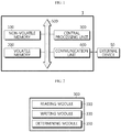
- FIG. 1 is a diagram schematically showing a functional configuration of a non-volatile memory updating apparatus according to an embodiment of the present disclosure
- FIG. 2 is a block diagram schematically showing a functional configuration of a central processing unit provided to the non-volatile memory updating apparatus according to an embodiment of the present disclosure.
- a non-volatile memory updating apparatus 1 includes a volatile memory 200 and a central processing unit 300.
- the volatile memory 200 may be configured to store an application code.
- the volatile memory 200 may be a memory device configured to store data.
- the application code may be a code designed using a programming language.
- the application code may be a program code associated with the operation of a BMS.
- the volatile memory 200 is a memory that stores data for operating a system when starting the system.
- the volatile memory 200 may be a memory that stores data only when the system is turned on and erases the stored data when the system is turned off.
- the volatile memory 200 may store the application code in a specific area therein.
- the volatile memory 200 may be implemented using a random access memory (RAM), a static RAM (SRAM), a dynamic RAM (DRAM), a synchronous DRAM (SDRAM), or the like.
- the non-volatile memory updating apparatus 1 may include a non-volatile memory 100.
- the non-volatile memory 100 may be a memory device that maintains the stored data even when a power supply is cut off.
- the non-volatile memory 100 may be implemented using a flash memory device, a read only memory (ROM), a programmable ROM (PROM), an electrically programmable ROM (EPROM), an electrically erasable and programmable ROM (EPROM), a resistive memory device (e.g., a phase-change RAM (PRAM), a ferroelectric RAM (FRAM) and a resistive RAM (RRAM)), or the like.
- ROM read only memory
- PROM programmable ROM
- EPROM electrically programmable ROM
- EPROM electrically erasable and programmable ROM
- a resistive memory device e.g., a phase-change RAM (PRAM), a ferroelectric RAM (FRAM) and a resistive RAM (RRAM)
- the volatile memory 200 and the non-volatile memory 100 may be electrically connected to the central processing unit 300 through a data bus 500 so as to be accessible by the central processing unit 300.
- the volatile memory 200 and the non-volatile memory 100 may store and/or update and/or erase and/or transmit data generated when a program including various control logics and/or a control logic performed by the central processing unit 300 is executed
- the central processing unit 300 may record an application code in the volatile memory 200. For example, as shown in FIG. 1 , the central processing unit 300 may access the volatile memory 200 through the data bus 500 and record the application code in the volatile memory 200 through the data bus 500.
- the central processing unit 300 may record the application code, which is recorded in the volatile memory 200, in the non-volatile memory 100. For example, as shown in FIG. 1 , the central processing unit 300 may access the volatile memory 200 and the non-volatile memory 100 through the data bus 500. In addition, the central processing unit 300 may transmit the application code from the volatile memory 200 to the non-volatile memory 100 through the data bus 500 to record the application code in the non-volatile memory 100.
- the central processing unit 300 may record a booting indicator indicating booting information of the application code in the non-volatile memory 100. For example, the central processing unit 300 may determine whether the application code is completely recorded in the non-volatile memory 100. For example, the central processing unit 300 may determine that the application code is completely recorded if a total size of the application code is recorded on the basis of the size (for example, byte) of the application code. In addition, the central processing unit 300 may record the booting indicator in the non-volatile memory 100 if the application code is completely recorded in the non-volatile memory 100.
- the booting indicator may indicate the booting information of the application code recorded in the non-volatile memory 100.
- the booting indicator may be a code executed by the central processing unit 300 before the application code is executed, in order to execute the application code.
- the booting indicator may indicate the booting information including a unique identifier, a location and a size of the application code.
- the central processing unit 300 may include a reading module 310, a writing module 330 and a determining module 350.
- the reading module 310 may access the volatile memory 200 or the non-volatile memory 100 and read the application code recorded in the volatile memory 200 or the non-volatile memory 100. For example, the reading module 310 may execute the application code recorded in the volatile memory 200 or the non-volatile memory 100. In addition, when reading the application code, the reading module 310 may sequentially read the application code from a memory area with a low address to a memory area with a high address.
- the writing module 330 may access the volatile memory 200 or the non-volatile memory 100 and record the application code in the volatile memory 200 or the non-volatile memory 100.
- the writing module 330 may store the application code recorded in the volatile memory 200 or the non-volatile memory 100.
- the writing module 330 may record the application code in a forward direction from a memory area with a low address to a memory area with a high address.
- the writing module 330 may record the application code in a reverse order from a memory area with a high address to a memory area with a low address.
- the end of the application code may be recorded in the memory area with a high address
- the start of the application code may be recorded in the memory area with a low address.
- the determining module 350 may determine whether the application code recorded in the non-volatile memory 100 is normally recorded. For example, the determining module 350 may determine whether all data of the application code is normally recorded in the non-volatile memory 100 without interruption. In addition, the determining module 350 may stop updating the application code when it is confirmed that the application code is normally recorded in the non-volatile memory 100. For example, the determining module 350 may stop updating the application code when it is confirmed that the application code is normally recorded in the non-volatile memory 100.
- the determining module 350 may compare the application code recorded in the volatile memory 200 and the application code recorded in the non-volatile memory 100. In addition, the determining module 350 may determine whether the application code is normally recorded by comparing the application code recorded in the volatile memory 200 and the application code recorded in the non-volatile memory 100.
- the determining module 350 may determine that the application code is normally recorded, if the application code recorded in the volatile memory 200 is identical to the application code recorded in the non-volatile memory 100.
- the central processing unit 300 may be implemented to optionally include a central processing unit (CPU), a processor, an application-specific integrated circuit (ASIC), other chipsets, a logic circuit, a register, and a communication modem and/or a data processing device, known in the art, to perform the above operation.
- CPU central processing unit
- ASIC application-specific integrated circuit
- the non-volatile memory updating apparatus 1 may further include a communication unit 400.
- the communication unit 400 may be configured to receive the application code from an external device 50.
- the communication unit 400 may receive the application code from the external device 50 by performing wired or wireless communication with the external device 50.
- the communication unit 400 may be electrically connected to the data bus 500 and may be connected to the non-volatile memory 100, the volatile memory 200 and the central processing unit 300 through the data bus 500, respectively.
- FIG. 3 is a table showing a memory map of a non-volatile memory, which is referred to by the non-volatile memory updating apparatus according to an embodiment of the present disclosure
- FIG. 4 is a diagram schematically showing a process of updating the non-volatile memory by the non-volatile memory updating apparatus according to an embodiment of the present disclosure.
- the central processing unit 300 may set a storage area in the non-volatile memory 100 in which the application code is stored.
- the central processing unit 300 may set the storage area in which application code is stored in a specific area of the non-volatile memory 100.
- the non-volatile memory 100 may include a first storage area 101, a second storage area 102, a third storage area 103, a fourth storage area 104, and a fifth storage area 105.
- the first storage area 101 may indicate a zeroth block and have addresses of Ox0100_0000 to 0x103FFFF with a size of 256 KB.
- the second storage area 102 may indicate a first block and have addresses of Ox0104_0000 to 0x107FFFF with a size of 256 KB.
- the third storage area 103 may represent a second block and have addresses from Ox0108_0000 to OxlOBFFFF with a size of 256 KB.
- the fourth storage area 104 may indicate a third block and have addresses of Ox010C_0000 to OxlOFFFFF with a size of 256KB.
- the fifth storage area 105 may indicate a fourth block and have addresses of 0x0110_0000 to 0x113FFFF with a size of 256 KB.
- the central processing unit 300 may record the application code in a reverse direction from a section with a high address in the storage area to a section with a low address in the storage area.
- the central processing unit 300 may record the application code in a reverse direction along the arrow of FIG. 4 from fifth storage area 105 to the first storage area 101 in order.
- the central processing unit 300 may record a booting indicator 110 in an area with a lower address lower than the address of the storage area in which the application code is stored. For example, the central processing unit 300 may determine the size of the application code, and may determine that the application code is completely recorded, if all data of the application code is recorded in the storage area on the basis of the size of the application code. Subsequently, the central processing unit 300 may record the booting indicator 110 in an area with a lower address than the address of the storage area in which the application code is stored.
- the central processing unit 300 may record the application code in the order from the final address of the second storage area 102 to the first storage area 101.
- the central processing unit 300 may record the booting indicator 110 immediately before the application code.
- the central processing unit 300 may record a final code of the application code in a final address of the second storage area 102, record a first code of the application code immediately after the booting indicator 110 of the first storage area 101, and record the booting indicator 110 at a first address of the first storage area 101.
- the central processing unit 300 may determine whether the application code is normally recorded, on the basis of the presence of the booting indicator 110 recorded in the non-volatile memory 100. For example, as shown in the embodiment of FIG. 4 , the central processing unit 300 may search for the booting indicator 110 recorded in the non-volatile memory 100, and if the booting indicator 110 exists in the non-volatile memory 100, the central processing unit 300 may determine whether the application code is normally recorded on the basis of this.
- the central processing unit 300 may check the presence of the booting indicator 110. In addition, if it is determined that the booting indicator 110 is normally recorded, the central processing unit 300 may execute the application code. For example, as shown in the embodiment of FIG. 4 , the central processing unit 300 may check the presence of the booting indicator 110 in order to execute the application code. In addition, if it is confirmed that the booting indicator 110 is normally recorded, the central processing unit 300 may execute the application code by sequentially reading the application code from an application code recorded immediately after the booting indicator 110.
- the non-volatile memory updating apparatus may check whether the application code is normally recorded only with the booting indicator 110, without having to record a separate flag (for example, Magic Flag) having a specific value in a specific area of the non-volatile memory 100.
- a separate flag for example, Magic Flag
- the non-volatile memory updating apparatus may include a battery management system (BMS). That is, the BMS according to the present disclosure may be included in the non-volatile memory updating apparatus of the present disclosure as described above. In this configuration, at least a part of the components of the non-volatile memory updating apparatus according to the present disclosure may be implemented by supplementing or adding functionality of components included in the conventional BMS.
- the central processing unit 300 and the non-volatile memory 100 of the non-volatile memory updating apparatus according to the present disclosure may be implemented as components of the BMS.
- the non-volatile memory updating apparatus may be provided to a battery pack. That is, the battery pack according to the present disclosure may include the non-volatile memory updating apparatus according to the present disclosure.
- the battery pack may include at least one secondary battery, the non-volatile memory updating apparatus, electrical components (such as a BMS, a relay and a fuse), a case and so on.
- FIG. 5 is a schematic flowchart for illustrating a non-volatile memory updating method according to an embodiment of the present disclosure.
- each step may be performed by any component of the non-volatile memory updating apparatus according to the present disclosure as described above.
- a non-volatile memory updating method includes a volatile memory recording step (S100), a non-volatile memory recording step (S110) and a booting indicator recording step (S120).
- the application code may be recorded in the volatile memory.
- the non-volatile memory recording step S110 the application code recorded in the volatile memory may be recorded in the non-volatile memory.
- the booting indicator recording step (S120) if the application code is completely recorded in the non-volatile memory, a booting indicator indicating booting information of the application code may be recorded in the non-volatile memory.
- the booting indicator recording step (S120) it is determined whether the application code recorded in the non-volatile memory is normally recorded, and then if it is confirmed that the application code is normally recorded in the non-volatile memory, updating the application code may be stopped.
- the booting indicator recording step (S120) it may be determined whether the application code is normally recorded, on the basis of the presence of the booting indicator recorded in the non-volatile memory.
- the non-volatile memory updating method may further include an application code executing.
- the application code executing step when the execution command for the application code is received, the presence of the booting indicator may be checked, and if it is confirmed that the booting indicator is normally recorded, the application code may be executed.
- the non-volatile memory recording step (S110) it may be determined whether the application code is normally recorded by comparing the application code recorded in the volatile memory and the application code recorded in the non-volatile memory.
- the non-volatile memory recording step (S110) if the application code recorded in the volatile memory is identical to the application code recorded in the non-volatile memory, it may be determined that the application code is normally recorded.
- a storage area in the non-volatile memory where the application code is stored may be set, and the application code may be recorded in a reverse direction from the a section with a high address in the storage area to a section with a low address in the storage area.
- the booting indicator recording step (S120) if the application code is completely recorded in the storage area, the booting indicator may be recorded in an area with a lower address than the address of the storage area where the application code is stored.
- the central processing unit may be implemented as a set of program modules.
- the program modules may be stored in a memory device and executed by the central processing unit.
- the recording medium includes at least one selected from the group consisting of a ROM, a RAM, a register, a CD-ROM, a magnetic tape, a hard disk, a floppy disk and an optical data recording device.
- the code system may be stored and executed in a distributed manner on computers connected through a network.
- functional programs, code and segments for implementing the combined control logics may be easily inferred by programmers in the technical field to which the present disclosure belongs.
Landscapes
- Engineering & Computer Science (AREA)
- Theoretical Computer Science (AREA)
- Software Systems (AREA)
- General Engineering & Computer Science (AREA)
- Physics & Mathematics (AREA)
- General Physics & Mathematics (AREA)
- Computer Security & Cryptography (AREA)
- Human Computer Interaction (AREA)
- Techniques For Improving Reliability Of Storages (AREA)
- Stored Programmes (AREA)
- Memory System (AREA)
Abstract
Description
- The present application claims priority to Korean Patent Application No.
10-2018-0109207 filed on September 12, 2018 - The present disclosure relates to a non-volatile memory updating apparatus and method, and more particularly, to a non-volatile memory updating apparatus and method capable of ensuring updating reliability while updating a non-volatile memory of a battery management system (BMS) provided to a battery pack.
- In recent years, the demand for portable electronic products such as notebook computers, video cameras and portable phones has increased sharply, and the energy storage batteries, robots and satellites has been active developed. Accordingly, high-performance secondary batteries allowing repeated charging and discharging are being actively studied.
- Secondary batteries commercially available at present include nickel-cadmium batteries, nickel-hydrogen batteries, nickel-zinc batteries, lithium secondary batteries and the like. Among them, the lithium secondary batteries have almost no memory effect compared to nickel-based secondary batteries and thus are in the limelight due to advantageous such as free charging and discharging, low self-discharge rate and high energy density.
- Batteries are used in a wide variety of applications, and large capacities are often required for devices such as electric-driven vehicles or smart grid systems to which batteries are frequently utilized. In order to increase the capacity of the battery, the capacity of the secondary battery, namely the capacity of a battery cell itself, may be increased. However, in this case, the capacity increase effect is not large and there is a physical limitation on the size expansion of the secondary battery. Thus, generally, a battery pack in which a plurality of battery modules are connected in series and in parallel is widely used.
- The battery pack includes a battery management system (BMS) having a plurality of chips and electrical circuits to measure a voltage, a current, a temperature, and the like of the battery and to control charging and discharging of the battery. For example, the BMS may include a chip such as a micro controller unit (MCU) having a central processing unit (CPU), a memory device, and the like.
- In general, the MCU stores a program for operating the BMS in a memory device inside the MCU, and the CPU reads the program and controls the overall operation of the system accordingly. The memory device for storing a program for operating the system employs a volatile memory (RAM: Random Access Memory) and a non-volatile memory (ROM: Read Only Memory).
- In the prior art, in order to update a non-volatile memory, a flag with a specific value (e.g., a Magic Flag) is recorded to a specific area of the non-volatile memory to check whether the program is normally recorded in the non-volatile memory. Also, by checking the flag, it is determined that the program is normally recorded in the non-volatile memory. However, in the process of recording the flag, it is inconvenient to separately create a specific area of the non-volatile memory and to continuously manage the specific area.
- In addition, in the prior art, after confirming that the application code is normally recorded by checking the flag, a booting indicator should be read to execute the application code, inconveniently.
- The present disclosure is designed to solve the problems of the related art, and therefore the present disclosure is directed to providing an improved non-volatile memory updating apparatus and method, which may ensure updating reliability while updating a non-volatile memory of a BMS provided to a battery pack.
- These and other objects and advantages of the present disclosure may be understood from the following detailed description and will become more fully apparent from the exemplary embodiments of the present disclosure. Also, it will be easily understood that the objects and advantages of the present disclosure may be realized by the means shown in the appended claims and combinations thereof.
- In one aspect of the present disclosure, there is provided a non-volatile memory updating apparatus for updating an application code stored in a non-volatile memory, the non-volatile memory updating apparatus comprising: a volatile memory configured to store the application code; and a central processing unit configured to record the application code in the volatile memory, record the application code, which is recorded in the volatile memory, in the non-volatile memory, and when the application code is completely recorded in the non-volatile memory, record a booting indicator indicating booting information of the application code in the non-volatile memory.
- In addition, the central processing unit may determine whether the application code recorded in the non-volatile memory is normally recorded, and stop updating the application code when it is confirmed that the application code is normally recorded in the non-volatile memory.
- In addition, the central processing unit may determine that the application code is normally recorded on the basis of the presence of the booting indicator recorded in the non-volatile memory.
- In addition, when receiving an execution command for the application code, the central processing unit may check the presence of the booting indicator, and when it is confirmed that the booting indicator is normally recorded, the central processing unit may execute the application code.
- In addition, the central processing unit may determine whether the application code is normally recorded by comparing the application code recorded in the volatile memory and the application code recorded in the non-volatile memory.
- In addition, the central processing unit may determine that the application code is normally recorded when the application code recorded in the volatile memory is identical to the application code recorded in the non-volatile memory.
- In addition, the central processing unit may set a storage area in the non-volatile memory in which the application code is recorded, and record the application code in a reverse direction from a section with a high address in the storage area to a section with a low address in the storage area.
- In addition, when the application code is completely recorded in the storage area, the central processing unit may record the booting indicator in an area with a lower address than an address of the storage area in which the application code is stored.
- In addition, the non-volatile memory updating apparatus according to an embodiment of the present disclosure may further comprise a communication unit configured to receive the application code from an external device.
- In addition, a battery management system (BMS) according to an embodiment of the present disclosure comprises the non-volatile memory updating apparatus according to the present disclosure.
- In addition, a battery pack according to an embodiment of the present disclosure comprises the non-volatile memory updating apparatus according to the present disclosure.
- In addition, according to an embodiment of the present disclosure, there is also provided a non-volatile memory updating method for updating an application code stored in a non-volatile memory, the non-volatile memory updating method comprising: recording the application code in a volatile memory; recording the application code, which is recorded in the volatile memory, in the non-volatile memory; and when the application code is completely recorded in the non-volatile memory, recording a booting indicator indicating booting information of the application code in the non-volatile memory.
- According to one aspect of the present disclosure, whether an application code is normally recorded may be confirmed only using a booting indicator, without having to write a flag having a specific value (e.g., Magic Flag) in a specific area of the non-volatile memory.
- According to another aspect of the present disclosure, since the process of recording a flag with a specific value (e.g., Magic Flag) may be excluded, it is possible to improve the operational efficiency of the non-volatile memory, and system errors caused by an error of the flag value or the like may be minimized or prevented.
- According to another aspect of the present disclosure, if an error occurs while updating the application code to stop the updating process, the booting indicator is not recorded. Thus, whether an application code is normally recorded may be confirmed only using a booting indicator, without having to write a flag having a specific value (e.g., Magic Flag) in a specific area of the non-volatile memory.
- The present disclosure may have various effects other than the above, and other effects of the present disclosure may be understood from the following description and more clearly figured out by the embodiments of the present disclosure.
- The accompanying drawings illustrate a preferred embodiment of the present disclosure and together with the foregoing disclosure, serve to provide further understanding of the technical features of the present disclosure, and thus, the present disclosure is not construed as being limited to the drawing.
-
FIG. 1 is a diagram schematically showing a functional configuration of a non-volatile memory updating apparatus according to an embodiment of the present disclosure. -
FIG. 2 is a block diagram schematically showing a functional configuration of a central processing unit provided to the non-volatile memory updating apparatus according to an embodiment of the present disclosure. -
FIG. 3 is a table showing a memory map of a non-volatile memory, which is referred to by the non-volatile memory updating apparatus according to an embodiment of the present disclosure. -
FIG. 4 is a diagram schematically showing a process of updating the non-volatile memory by the non-volatile memory updating apparatus according to an embodiment of the present disclosure. -
FIG. 5 is a flowchart schematically showing a non-volatile memory updating method according to an embodiment of the present disclosure. - Hereinafter, preferred embodiments of the present disclosure will be described in detail with reference to the accompanying drawings. Prior to the description, it should be understood that the terms used in the specification and the appended claims should not be construed as limited to general and dictionary meanings, but interpreted based on the meanings and concepts corresponding to technical aspects of the present disclosure on the basis of the principle that the inventor is allowed to define terms appropriately for the best explanation.
- Therefore, the description proposed herein is just a preferable example for the purpose of illustrations only, not intended to limit the scope of the disclosure, so it should be understood that other equivalents and modifications could be made thereto without departing from the scope of the disclosure.
- In addition, in the present disclosure, if it is determined that a detailed description of a related known structure or function may obscure the subject matter of the present disclosure, the detailed description will be omitted.
- Throughout the specification, when a portion is referred to as "comprising" or "including" any element, it means that the portion may include other elements further, without excluding other elements, unless specifically stated otherwise.
- In addition, throughout the specification, when a portion is referred to as being "connected" to another portion, it is not limited to the case that they are "directly connected", but it also includes the case where they are "indirectly connected" with another element being interposed between them.
- A non-volatile
memory updating apparatus 1 according to an embodiment of the present disclosure may be a non-volatile memory updating apparatus for updating an application code stored in a non-volatilememory 100. For example, the non-volatilememory updating apparatus 1 according to an embodiment of the present disclosure may be a device for updating an application code stored in anon-volatile memory 100 of a battery management system (BMS) included in a battery pack. For example, thenon-volatile memory 100 according to an embodiment of the present disclosure may be a flash memory. In addition, the non-volatilememory updating apparatus 1 according to an embodiment of the present disclosure may be a microcontroller unit (MCU) provided in the BMS. -
FIG. 1 is a diagram schematically showing a functional configuration of a non-volatile memory updating apparatus according to an embodiment of the present disclosure, andFIG. 2 is a block diagram schematically showing a functional configuration of a central processing unit provided to the non-volatile memory updating apparatus according to an embodiment of the present disclosure. - Referring to
FIGS. 1 and 2 , a non-volatilememory updating apparatus 1 according to an embodiment of the present disclosure includes avolatile memory 200 and acentral processing unit 300. - The
volatile memory 200 may be configured to store an application code. For example, thevolatile memory 200 may be a memory device configured to store data. Here, the application code may be a code designed using a programming language. For example, the application code may be a program code associated with the operation of a BMS. - The
volatile memory 200 according to an embodiment of the present disclosure is a memory that stores data for operating a system when starting the system. Thevolatile memory 200 may be a memory that stores data only when the system is turned on and erases the stored data when the system is turned off. In addition, thevolatile memory 200 may store the application code in a specific area therein. For example, thevolatile memory 200 may be implemented using a random access memory (RAM), a static RAM (SRAM), a dynamic RAM (DRAM), a synchronous DRAM (SDRAM), or the like. - Also, as shown in
FIG. 1 , the non-volatilememory updating apparatus 1 according to an embodiment of the present disclosure may include anon-volatile memory 100. - The
non-volatile memory 100 may be a memory device that maintains the stored data even when a power supply is cut off. For example, thenon-volatile memory 100 may be implemented using a flash memory device, a read only memory (ROM), a programmable ROM (PROM), an electrically programmable ROM (EPROM), an electrically erasable and programmable ROM (EPROM), a resistive memory device (e.g., a phase-change RAM (PRAM), a ferroelectric RAM (FRAM) and a resistive RAM (RRAM)), or the like. - In addition, as shown in
FIG. 1 , thevolatile memory 200 and thenon-volatile memory 100 according to an embodiment of the present disclosure may be electrically connected to thecentral processing unit 300 through adata bus 500 so as to be accessible by thecentral processing unit 300. Also, thevolatile memory 200 and thenon-volatile memory 100 may store and/or update and/or erase and/or transmit data generated when a program including various control logics and/or a control logic performed by thecentral processing unit 300 is executed - The
central processing unit 300 may record an application code in thevolatile memory 200. For example, as shown inFIG. 1 , thecentral processing unit 300 may access thevolatile memory 200 through thedata bus 500 and record the application code in thevolatile memory 200 through thedata bus 500. - In addition, the
central processing unit 300 may record the application code, which is recorded in thevolatile memory 200, in thenon-volatile memory 100. For example, as shown inFIG. 1 , thecentral processing unit 300 may access thevolatile memory 200 and thenon-volatile memory 100 through thedata bus 500. In addition, thecentral processing unit 300 may transmit the application code from thevolatile memory 200 to thenon-volatile memory 100 through thedata bus 500 to record the application code in thenon-volatile memory 100. - In addition, if the application code is completely recorded in the
non-volatile memory 100, thecentral processing unit 300 may record a booting indicator indicating booting information of the application code in thenon-volatile memory 100. For example, thecentral processing unit 300 may determine whether the application code is completely recorded in thenon-volatile memory 100. For example, thecentral processing unit 300 may determine that the application code is completely recorded if a total size of the application code is recorded on the basis of the size (for example, byte) of the application code. In addition, thecentral processing unit 300 may record the booting indicator in thenon-volatile memory 100 if the application code is completely recorded in thenon-volatile memory 100. Here, the booting indicator may indicate the booting information of the application code recorded in thenon-volatile memory 100. For example, the booting indicator may be a code executed by thecentral processing unit 300 before the application code is executed, in order to execute the application code. In addition, the booting indicator may indicate the booting information including a unique identifier, a location and a size of the application code. - Preferably, as shown in
FIG. 2 , thecentral processing unit 300 according to an embodiment of the present disclosure may include areading module 310, awriting module 330 and a determiningmodule 350. - The
reading module 310 may access thevolatile memory 200 or thenon-volatile memory 100 and read the application code recorded in thevolatile memory 200 or thenon-volatile memory 100. For example, thereading module 310 may execute the application code recorded in thevolatile memory 200 or thenon-volatile memory 100. In addition, when reading the application code, thereading module 310 may sequentially read the application code from a memory area with a low address to a memory area with a high address. - The
writing module 330 may access thevolatile memory 200 or thenon-volatile memory 100 and record the application code in thevolatile memory 200 or thenon-volatile memory 100. For example, thewriting module 330 may store the application code recorded in thevolatile memory 200 or thenon-volatile memory 100. When writing the application code, thewriting module 330 may record the application code in a forward direction from a memory area with a low address to a memory area with a high address. - In addition, when recording the application code, the
writing module 330 according to an embodiment of the present disclosure may record the application code in a reverse order from a memory area with a high address to a memory area with a low address. In this case, the end of the application code may be recorded in the memory area with a high address, and the start of the application code may be recorded in the memory area with a low address. - The determining
module 350 may determine whether the application code recorded in thenon-volatile memory 100 is normally recorded. For example, the determiningmodule 350 may determine whether all data of the application code is normally recorded in thenon-volatile memory 100 without interruption. In addition, the determiningmodule 350 may stop updating the application code when it is confirmed that the application code is normally recorded in thenon-volatile memory 100. For example, the determiningmodule 350 may stop updating the application code when it is confirmed that the application code is normally recorded in thenon-volatile memory 100. - Preferably, the determining
module 350 according to an embodiment of the present disclosure may compare the application code recorded in thevolatile memory 200 and the application code recorded in thenon-volatile memory 100. In addition, the determiningmodule 350 may determine whether the application code is normally recorded by comparing the application code recorded in thevolatile memory 200 and the application code recorded in thenon-volatile memory 100. - Preferably, the determining
module 350 according to an embodiment of the present disclosure may determine that the application code is normally recorded, if the application code recorded in thevolatile memory 200 is identical to the application code recorded in thenon-volatile memory 100. - Meanwhile, the
central processing unit 300 may be implemented to optionally include a central processing unit (CPU), a processor, an application-specific integrated circuit (ASIC), other chipsets, a logic circuit, a register, and a communication modem and/or a data processing device, known in the art, to perform the above operation. - Preferably, as shown in
FIG. 1 , the non-volatilememory updating apparatus 1 according to an embodiment of the present disclosure may further include acommunication unit 400. - The
communication unit 400 may be configured to receive the application code from anexternal device 50. For example, as shown inFIG. 1 , thecommunication unit 400 may receive the application code from theexternal device 50 by performing wired or wireless communication with theexternal device 50. In addition, thecommunication unit 400 may be electrically connected to thedata bus 500 and may be connected to thenon-volatile memory 100, thevolatile memory 200 and thecentral processing unit 300 through thedata bus 500, respectively. -
FIG. 3 is a table showing a memory map of a non-volatile memory, which is referred to by the non-volatile memory updating apparatus according to an embodiment of the present disclosure, andFIG. 4 is a diagram schematically showing a process of updating the non-volatile memory by the non-volatile memory updating apparatus according to an embodiment of the present disclosure. - Referring to
FIGS. 3 and 4 , thecentral processing unit 300 according to an embodiment of the present disclosure may set a storage area in thenon-volatile memory 100 in which the application code is stored. For example, thecentral processing unit 300 may set the storage area in which application code is stored in a specific area of thenon-volatile memory 100. For example, as shown in the table ofFIG. 3 , thenon-volatile memory 100 may include afirst storage area 101, asecond storage area 102, athird storage area 103, afourth storage area 104, and afifth storage area 105. - The
first storage area 101 may indicate a zeroth block and have addresses of Ox0100_0000 to 0x103FFFF with a size of 256 KB. In addition, thesecond storage area 102 may indicate a first block and have addresses of Ox0104_0000 to 0x107FFFF with a size of 256 KB. In addition, thethird storage area 103 may represent a second block and have addresses from Ox0108_0000 to OxlOBFFFF with a size of 256 KB. In addition, thefourth storage area 104 may indicate a third block and have addresses of Ox010C_0000 to OxlOFFFFF with a size of 256KB. In addition, thefifth storage area 105 may indicate a fourth block and have addresses of 0x0110_0000 to 0x113FFFF with a size of 256 KB. - Preferably, the
central processing unit 300 may record the application code in a reverse direction from a section with a high address in the storage area to a section with a low address in the storage area. For example, as shown inFIG. 4 , thecentral processing unit 300 may record the application code in a reverse direction along the arrow ofFIG. 4 fromfifth storage area 105 to thefirst storage area 101 in order. - Preferably, if the application code is completely recorded in the storage area, the
central processing unit 300 may record a bootingindicator 110 in an area with a lower address lower than the address of the storage area in which the application code is stored. For example, thecentral processing unit 300 may determine the size of the application code, and may determine that the application code is completely recorded, if all data of the application code is recorded in the storage area on the basis of the size of the application code. Subsequently, thecentral processing unit 300 may record the bootingindicator 110 in an area with a lower address than the address of the storage area in which the application code is stored. - For example, in the embodiment of
FIGS. 3 and 4 , if the size of the application code is 508 KB and the size of the bootingindicator 110 is 4 KB, thecentral processing unit 300 may record the application code in the order from the final address of thesecond storage area 102 to thefirst storage area 101. In addition, if the application code is completely recorded, thecentral processing unit 300 may record the bootingindicator 110 immediately before the application code. In this case, thecentral processing unit 300 may record a final code of the application code in a final address of thesecond storage area 102, record a first code of the application code immediately after thebooting indicator 110 of thefirst storage area 101, and record the bootingindicator 110 at a first address of thefirst storage area 101. - Preferably, the
central processing unit 300 may determine whether the application code is normally recorded, on the basis of the presence of the bootingindicator 110 recorded in thenon-volatile memory 100. For example, as shown in the embodiment ofFIG. 4 , thecentral processing unit 300 may search for the bootingindicator 110 recorded in thenon-volatile memory 100, and if the bootingindicator 110 exists in thenon-volatile memory 100, thecentral processing unit 300 may determine whether the application code is normally recorded on the basis of this. - Preferably, if the
central processing unit 300 receives an execution command for the application code, thecentral processing unit 300 may check the presence of the bootingindicator 110. In addition, if it is determined that the bootingindicator 110 is normally recorded, thecentral processing unit 300 may execute the application code. For example, as shown in the embodiment ofFIG. 4 , thecentral processing unit 300 may check the presence of the bootingindicator 110 in order to execute the application code. In addition, if it is confirmed that the bootingindicator 110 is normally recorded, thecentral processing unit 300 may execute the application code by sequentially reading the application code from an application code recorded immediately after thebooting indicator 110. - Through this configuration, the non-volatile memory updating apparatus according to an embodiment of the present disclosure may check whether the application code is normally recorded only with the booting
indicator 110, without having to record a separate flag (for example, Magic Flag) having a specific value in a specific area of thenon-volatile memory 100. - The non-volatile memory updating apparatus according to the present disclosure may include a battery management system (BMS). That is, the BMS according to the present disclosure may be included in the non-volatile memory updating apparatus of the present disclosure as described above. In this configuration, at least a part of the components of the non-volatile memory updating apparatus according to the present disclosure may be implemented by supplementing or adding functionality of components included in the conventional BMS. For example, the
central processing unit 300 and thenon-volatile memory 100 of the non-volatile memory updating apparatus according to the present disclosure may be implemented as components of the BMS. - In addition, the non-volatile memory updating apparatus according to the present disclosure may be provided to a battery pack. That is, the battery pack according to the present disclosure may include the non-volatile memory updating apparatus according to the present disclosure. Here, the battery pack may include at least one secondary battery, the non-volatile memory updating apparatus, electrical components (such as a BMS, a relay and a fuse), a case and so on.
-
FIG. 5 is a schematic flowchart for illustrating a non-volatile memory updating method according to an embodiment of the present disclosure. InFIG. 5 , each step may be performed by any component of the non-volatile memory updating apparatus according to the present disclosure as described above. - As shown in
FIG. 5 , a non-volatile memory updating method according to an embodiment of the present disclosure includes a volatile memory recording step (S100), a non-volatile memory recording step (S110) and a booting indicator recording step (S120). - First, in the volatile memory recording step (S100), the application code may be recorded in the volatile memory. Subsequently, in the non-volatile memory recording step S110, the application code recorded in the volatile memory may be recorded in the non-volatile memory. Subsequently, in the booting indicator recording step (S120), if the application code is completely recorded in the non-volatile memory, a booting indicator indicating booting information of the application code may be recorded in the non-volatile memory.
- Preferably, in the booting indicator recording step (S120) according to an embodiment of the present disclosure, it is determined whether the application code recorded in the non-volatile memory is normally recorded, and then if it is confirmed that the application code is normally recorded in the non-volatile memory, updating the application code may be stopped.
- Preferably, in the booting indicator recording step (S120) according to an embodiment of the present disclosure, it may be determined whether the application code is normally recorded, on the basis of the presence of the booting indicator recorded in the non-volatile memory.
- Preferably, the non-volatile memory updating method according to an embodiment of the present disclosure may further include an application code executing. In the application code executing step, when the execution command for the application code is received, the presence of the booting indicator may be checked, and if it is confirmed that the booting indicator is normally recorded, the application code may be executed.
- Preferably, in the non-volatile memory recording step (S110) according to an embodiment of the present disclosure, it may be determined whether the application code is normally recorded by comparing the application code recorded in the volatile memory and the application code recorded in the non-volatile memory.
- Preferably, in the non-volatile memory recording step (S110) according to an embodiment of the present disclosure, if the application code recorded in the volatile memory is identical to the application code recorded in the non-volatile memory, it may be determined that the application code is normally recorded.
- Preferably, in the non-volatile memory recording step (S110) according to an embodiment of the present disclosure, a storage area in the non-volatile memory where the application code is stored may be set, and the application code may be recorded in a reverse direction from the a section with a high address in the storage area to a section with a low address in the storage area.
- Preferably, in the booting indicator recording step (S120) according to an embodiment of the present disclosure, if the application code is completely recorded in the storage area, the booting indicator may be recorded in an area with a lower address than the address of the storage area where the application code is stored.
- Also, when the control logic is implemented in software, the central processing unit may be implemented as a set of program modules. At this time, the program modules may be stored in a memory device and executed by the central processing unit.
- In addition, there is no particular limitation on the types of various control logics of the central processing unit, as long as one or more control logics are combined and the combined control logic is written in a computer-readable code system so that the computer-readable access is possible. As one example, the recording medium includes at least one selected from the group consisting of a ROM, a RAM, a register, a CD-ROM, a magnetic tape, a hard disk, a floppy disk and an optical data recording device. In addition, the code system may be stored and executed in a distributed manner on computers connected through a network. Moreover, functional programs, code and segments for implementing the combined control logics may be easily inferred by programmers in the technical field to which the present disclosure belongs.
- The present disclosure has been described in detail. However, it should be understood that the detailed description and specific examples, while indicating preferred embodiments of the disclosure, are given by way of illustration only, since various changes and modifications within the scope of the disclosure will become apparent to those skilled in the art from this detailed description.
-
- 1:
- non-volatile memory updating apparatus
- 50:
- external device
- 100:
- non-volatile memory
- 110:
- booting indicator
- 200:
- volatile memory
- 300:
- central processing unit
- 310:
- reading module
- 330:
- writing module
- 350:
- determining module
- 400:
- communication unit
- 500:
- data bus
Claims (12)
- A non-volatile memory updating apparatus for updating an application code stored in a non-volatile memory, the non-volatile memory updating apparatus comprising:a volatile memory configured to store the application code; anda central processing unit configured to record the application code in the volatile memory, record the application code, which is recorded in the volatile memory, in the non-volatile memory, and when the application code is completely recorded in the non-volatile memory, record a booting indicator indicating booting information of the application code in the non-volatile memory.
- The non-volatile memory updating apparatus according to claim 1,
wherein the central processing unit is configured to determine whether the application code recorded in the non-volatile memory is normally recorded, and stop updating the application code when it is confirmed that the application code is normally recorded in the non-volatile memory. - The non-volatile memory updating apparatus according to claim 1,
wherein the central processing unit is configured to determine that the application code is normally recorded on the basis of the presence of the booting indicator recorded in the non-volatile memory. - The non-volatile memory updating apparatus according to claim 3,
wherein when receiving an execution command for the application code, the central processing unit is configured to check the presence of the booting indicator, and when it is confirmed that the booting indicator is normally recorded, the central processing unit is configured to execute the application code. - The non-volatile memory updating apparatus according to claim 1,
wherein the central processing unit is configured to determine whether the application code is normally recorded by comparing the application code recorded in the volatile memory and the application code recorded in the non-volatile memory. - The non-volatile memory updating apparatus according to claim 5,
wherein the central processing unit is configured to determine that the application code is normally recorded when the application code recorded in the volatile memory is identical to the application code recorded in the non-volatile memory. - The non-volatile memory updating apparatus according to claim 1,
wherein the central processing unit is configured to set a storage area in the non-volatile memory in which the application code is recorded, and record the application code in a reverse direction from a section with a high address in the storage area to a section with a low address in the storage area. - The non-volatile memory updating apparatus according to claim 7,
wherein when the application code is completely recorded in the storage area, the central processing unit is configured to record the booting indicator in an area with a lower address than an address of the storage area in which the application code is stored. - The non-volatile memory updating apparatus according to claim 1, further comprising:
a communication unit configured to receive the application code from an external device. - A battery management system (BMS), comprising the non-volatile memory updating apparatus according to any one of claims 1 to 9.
- A battery pack, comprising the non-volatile memory updating apparatus according to any one of claims 1 to 9.
- A non-volatile memory updating method for updating an application code stored in a non-volatile memory, the non-volatile memory updating method comprising:recording the application code in a volatile memory;recording the application code, which is recorded in the volatile memory, in the non-volatile memory; andwhen the application code is completely recorded in the non-volatile memory, recording a booting indicator indicating booting information of the application code in the non-volatile memory.
Applications Claiming Priority (2)
| Application Number | Priority Date | Filing Date | Title |
|---|---|---|---|
| KR1020180109207A KR102324263B1 (en) | 2018-09-12 | 2018-09-12 | Apparatus and method for updating nonvolatile memory |
| PCT/KR2019/011354 WO2020055025A1 (en) | 2018-09-12 | 2019-09-03 | Non-volatile memory updating device and method |
Publications (3)
| Publication Number | Publication Date |
|---|---|
| EP3731083A1 true EP3731083A1 (en) | 2020-10-28 |
| EP3731083A4 EP3731083A4 (en) | 2021-01-27 |
| EP3731083B1 EP3731083B1 (en) | 2025-08-20 |
Family
ID=69777959
Family Applications (1)
| Application Number | Title | Priority Date | Filing Date |
|---|---|---|---|
| EP19861140.2A Active EP3731083B1 (en) | 2018-09-12 | 2019-09-03 | Non-volatile memory updating apparatus and method |
Country Status (8)
| Country | Link |
|---|---|
| US (2) | US20200348853A1 (en) |
| EP (1) | EP3731083B1 (en) |
| JP (1) | JP7072660B2 (en) |
| KR (1) | KR102324263B1 (en) |
| CN (1) | CN111373368B (en) |
| ES (1) | ES3042169T3 (en) |
| HU (1) | HUE072973T2 (en) |
| WO (1) | WO2020055025A1 (en) |
Families Citing this family (1)
| Publication number | Priority date | Publication date | Assignee | Title |
|---|---|---|---|---|
| CN113721967B (en) * | 2021-08-30 | 2024-07-05 | 苏州磐联集成电路科技股份有限公司 | Differential packet generation method, differential packet generation device, and upgrade method |
Family Cites Families (24)
| Publication number | Priority date | Publication date | Assignee | Title |
|---|---|---|---|---|
| US4498151A (en) * | 1980-04-17 | 1985-02-05 | Texas Instruments Incorporated | On board non-volatile memory programming |
| US6594723B1 (en) * | 1999-09-07 | 2003-07-15 | Microsoft Corporation | Method and apparatus for updating data in nonvolatile memory |
| JP3474850B2 (en) * | 2000-01-12 | 2003-12-08 | 松下電器産業株式会社 | Battery power unit |
| US6993648B2 (en) * | 2001-08-16 | 2006-01-31 | Lenovo (Singapore) Pte. Ltd. | Proving BIOS trust in a TCPA compliant system |
| JP2004005152A (en) * | 2002-05-31 | 2004-01-08 | Hitachi Unisia Automotive Ltd | Non-volatile memory rewriting device |
| JP2004013477A (en) * | 2002-06-06 | 2004-01-15 | Nec Viewtechnology Ltd | Method for selecting and updating boot program and flash memory using the same |
| EP1634168A1 (en) * | 2003-06-03 | 2006-03-15 | Koninklijke Philips Electronics N.V. | Booting from non-volatile memory |
| CN100469001C (en) * | 2004-06-18 | 2009-03-11 | 宏碁股份有限公司 | System and method for updating software program by using general plug-and-play communication protocol |
| US9696980B2 (en) * | 2006-10-24 | 2017-07-04 | Medapps, Inc. | Method for remote provisioning of electronic devices by overlaying an initial application image with a retrieved application image |
| CN101030148A (en) * | 2007-03-09 | 2007-09-05 | 华为技术有限公司 | Method and device for realizing double mapping |
| US20090006835A1 (en) * | 2007-06-29 | 2009-01-01 | Samsung Electronics Co., Ltd | Electronic device and control method thereof |
| CN102135891B (en) * | 2010-01-21 | 2013-06-26 | 杭州华三通信技术有限公司 | System capable of realizing bootload, bootload control device and method |
| EP2372538A1 (en) * | 2010-03-23 | 2011-10-05 | ST-Ericsson SA | Processing IC with embedded non volatile memory |
| JP5418348B2 (en) * | 2010-03-23 | 2014-02-19 | ヤマハ株式会社 | Information processing apparatus and karaoke apparatus |
| US8539472B2 (en) * | 2010-06-09 | 2013-09-17 | Lear Corporation | Method and system of updating shared memory |
| US8495601B2 (en) * | 2010-06-09 | 2013-07-23 | Lear Corporation | Shared memory architecture |
| JP2013211974A (en) * | 2012-03-30 | 2013-10-10 | Renesas Electronics Corp | Semiconductor device for battery control, and battery pack |
| KR20130111750A (en) * | 2012-04-02 | 2013-10-11 | 현대모비스 주식회사 | Head-unit system for vehicle, and control method thereof |
| KR101351752B1 (en) * | 2012-12-21 | 2014-01-15 | 넥스콘 테크놀러지 주식회사 | System of downloading firm ware for wiress |
| KR102261815B1 (en) * | 2014-10-30 | 2021-06-07 | 삼성전자주식회사 | Data storage device for reducing firmware update time, and data processing system including the same |
| US20170010896A1 (en) * | 2015-07-06 | 2017-01-12 | Lear Corporation | Shared Memory Architecture Autoupdater |
| CN107870775A (en) * | 2016-09-26 | 2018-04-03 | 深圳市中兴微电子技术有限公司 | A method for updating processor and BootLoader program |
| KR20180109207A (en) | 2017-03-27 | 2018-10-08 | 노승우 | Flexible Air Nurse Starion for Home Healthcare |
| US10593412B2 (en) * | 2018-07-19 | 2020-03-17 | Micron Technology, Inc. | Using a status indicator in a memory sub-system to detect an event |
-
2018
- 2018-09-12 KR KR1020180109207A patent/KR102324263B1/en active Active
-
2019
- 2019-09-03 US US16/763,066 patent/US20200348853A1/en not_active Abandoned
- 2019-09-03 HU HUE19861140A patent/HUE072973T2/en unknown
- 2019-09-03 JP JP2020537504A patent/JP7072660B2/en active Active
- 2019-09-03 ES ES19861140T patent/ES3042169T3/en active Active
- 2019-09-03 CN CN201980005775.9A patent/CN111373368B/en active Active
- 2019-09-03 EP EP19861140.2A patent/EP3731083B1/en active Active
- 2019-09-03 WO PCT/KR2019/011354 patent/WO2020055025A1/en not_active Ceased
-
2023
- 2023-04-10 US US18/132,518 patent/US20230244381A1/en not_active Abandoned
Also Published As
| Publication number | Publication date |
|---|---|
| EP3731083A4 (en) | 2021-01-27 |
| KR20200030394A (en) | 2020-03-20 |
| CN111373368B (en) | 2023-11-14 |
| US20230244381A1 (en) | 2023-08-03 |
| KR102324263B1 (en) | 2021-11-08 |
| JP2021509990A (en) | 2021-04-08 |
| EP3731083B1 (en) | 2025-08-20 |
| CN111373368A (en) | 2020-07-03 |
| JP7072660B2 (en) | 2022-05-20 |
| US20200348853A1 (en) | 2020-11-05 |
| WO2020055025A1 (en) | 2020-03-19 |
| ES3042169T3 (en) | 2025-11-18 |
| HUE072973T2 (en) | 2025-12-28 |
Similar Documents
| Publication | Publication Date | Title |
|---|---|---|
| EP3262508B1 (en) | Patrol scrub periods based on power status | |
| JP2008511913A (en) | Power loss recovery mechanism based on volatile memory | |
| US7786695B2 (en) | Configurable battery management system with embedded SRAM in chip architecture | |
| US11942608B2 (en) | Device battery and unmanned aerial vehicle | |
| CN104778974A (en) | Serial memory device alert of an external host to completion of an internally self-timed operation | |
| CN106716161A (en) | Cell controlling method and system, and cell | |
| CN112622681A (en) | Charging control method and device | |
| US20230244381A1 (en) | Non-Volatile Memory Updating Apparatus and Method | |
| WO2020015502A1 (en) | Method and device for tracking overdischarge of battery, chip, battery and aircraft | |
| CN103631677B (en) | A kind of method that PLC device power-down data keeps | |
| US20080181008A1 (en) | Flash memory system capable of improving access performance and access method thereof | |
| CN108345430B (en) | Nand flash element and operation control method and device thereof | |
| CN102708923A (en) | Semiconductor integrated circuit and control method | |
| CN109918228B (en) | Data power failure maintaining method and system | |
| CN104008020B (en) | Robust sector ID scheme for tracking dead sector to search for and transcribe automatically | |
| CN112771503A (en) | Error recovery method, microcontroller unit using the same, and battery device including the microcontroller unit | |
| US12007894B2 (en) | Battery management apparatus and method | |
| CN110011369A (en) | Charge control method, equipment and system | |
| CN104575605A (en) | Memory device and method for booting system using non-volatile memory | |
| CN112199045A (en) | Storage device and data manipulation method | |
| US20170046084A1 (en) | Memory control device, memory device, and memory control method | |
| US20110078400A1 (en) | Battery pack, and method of controlling operation of data flash | |
| CN111159057A (en) | System and method for recording accumulated power-on times of task machine under battery-free condition | |
| CN111753337B (en) | A SOC processing method for unexpected power failure of energy storage battery management system | |
| CN108255540A (en) | A kind of Nand flash elements and its loading control method and device |
Legal Events
| Date | Code | Title | Description |
|---|---|---|---|
| STAA | Information on the status of an ep patent application or granted ep patent |
Free format text: STATUS: THE INTERNATIONAL PUBLICATION HAS BEEN MADE |
|
| PUAI | Public reference made under article 153(3) epc to a published international application that has entered the european phase |
Free format text: ORIGINAL CODE: 0009012 |
|
| STAA | Information on the status of an ep patent application or granted ep patent |
Free format text: STATUS: REQUEST FOR EXAMINATION WAS MADE |
|
| 17P | Request for examination filed |
Effective date: 20200721 |
|
| AK | Designated contracting states |
Kind code of ref document: A1 Designated state(s): AL AT BE BG CH CY CZ DE DK EE ES FI FR GB GR HR HU IE IS IT LI LT LU LV MC MK MT NL NO PL PT RO RS SE SI SK SM TR |
|
| AX | Request for extension of the european patent |
Extension state: BA ME |
|
| A4 | Supplementary search report drawn up and despatched |
Effective date: 20210111 |
|
| RIC1 | Information provided on ipc code assigned before grant |
Ipc: G06F 8/654 20180101AFI20201218BHEP Ipc: G06F 8/65 20180101ALI20201218BHEP Ipc: G06F 9/4401 20180101ALI20201218BHEP |
|
| DAV | Request for validation of the european patent (deleted) | ||
| DAX | Request for extension of the european patent (deleted) | ||
| RAP1 | Party data changed (applicant data changed or rights of an application transferred) |
Owner name: LG ENERGY SOLUTION LTD. |
|
| RAP3 | Party data changed (applicant data changed or rights of an application transferred) |
Owner name: LG ENERGY SOLUTION, LTD. |
|
| STAA | Information on the status of an ep patent application or granted ep patent |
Free format text: STATUS: EXAMINATION IS IN PROGRESS |
|
| 17Q | First examination report despatched |
Effective date: 20220408 |
|
| GRAP | Despatch of communication of intention to grant a patent |
Free format text: ORIGINAL CODE: EPIDOSNIGR1 |
|
| STAA | Information on the status of an ep patent application or granted ep patent |
Free format text: STATUS: GRANT OF PATENT IS INTENDED |
|
| INTG | Intention to grant announced |
Effective date: 20250422 |
|
| P01 | Opt-out of the competence of the unified patent court (upc) registered |
Free format text: CASE NUMBER: APP_21307/2025 Effective date: 20250506 |
|
| GRAS | Grant fee paid |
Free format text: ORIGINAL CODE: EPIDOSNIGR3 |
|
| GRAA | (expected) grant |
Free format text: ORIGINAL CODE: 0009210 |
|
| STAA | Information on the status of an ep patent application or granted ep patent |
Free format text: STATUS: THE PATENT HAS BEEN GRANTED |
|
| AK | Designated contracting states |
Kind code of ref document: B1 Designated state(s): AL AT BE BG CH CY CZ DE DK EE ES FI FR GB GR HR HU IE IS IT LI LT LU LV MC MK MT NL NO PL PT RO RS SE SI SK SM TR |
|
| REG | Reference to a national code |
Ref country code: GB Ref legal event code: FG4D |
|
| REG | Reference to a national code |
Ref country code: CH Ref legal event code: EP |
|
| REG | Reference to a national code |
Ref country code: IE Ref legal event code: FG4D |
|
| REG | Reference to a national code |
Ref country code: DE Ref legal event code: R096 Ref document number: 602019074520 Country of ref document: DE |
|
| PGFP | Annual fee paid to national office [announced via postgrant information from national office to epo] |
Ref country code: DE Payment date: 20250908 Year of fee payment: 7 |
|
| PGFP | Annual fee paid to national office [announced via postgrant information from national office to epo] |
Ref country code: BE Payment date: 20250820 Year of fee payment: 7 Ref country code: GB Payment date: 20250909 Year of fee payment: 7 |
|
| PGFP | Annual fee paid to national office [announced via postgrant information from national office to epo] |
Ref country code: FR Payment date: 20250909 Year of fee payment: 7 |
|
| PGFP | Annual fee paid to national office [announced via postgrant information from national office to epo] |
Ref country code: HU Payment date: 20251029 Year of fee payment: 7 |
|
| REG | Reference to a national code |
Ref country code: ES Ref legal event code: FG2A Ref document number: 3042169 Country of ref document: ES Kind code of ref document: T3 Effective date: 20251118 |
|
| REG | Reference to a national code |
Ref country code: NL Ref legal event code: MP Effective date: 20250820 |
|
| REG | Reference to a national code |
Ref country code: HU Ref legal event code: AG4A Ref document number: E072973 Country of ref document: HU |
|
| PG25 | Lapsed in a contracting state [announced via postgrant information from national office to epo] |
Ref country code: IS Free format text: LAPSE BECAUSE OF FAILURE TO SUBMIT A TRANSLATION OF THE DESCRIPTION OR TO PAY THE FEE WITHIN THE PRESCRIBED TIME-LIMIT Effective date: 20251220 |
|
| PG25 | Lapsed in a contracting state [announced via postgrant information from national office to epo] |
Ref country code: NO Free format text: LAPSE BECAUSE OF FAILURE TO SUBMIT A TRANSLATION OF THE DESCRIPTION OR TO PAY THE FEE WITHIN THE PRESCRIBED TIME-LIMIT Effective date: 20251120 |
|
| REG | Reference to a national code |
Ref country code: LT Ref legal event code: MG9D |
|
| PG25 | Lapsed in a contracting state [announced via postgrant information from national office to epo] |
Ref country code: PT Free format text: LAPSE BECAUSE OF FAILURE TO SUBMIT A TRANSLATION OF THE DESCRIPTION OR TO PAY THE FEE WITHIN THE PRESCRIBED TIME-LIMIT Effective date: 20251222 |
|
| PG25 | Lapsed in a contracting state [announced via postgrant information from national office to epo] |
Ref country code: FI Free format text: LAPSE BECAUSE OF FAILURE TO SUBMIT A TRANSLATION OF THE DESCRIPTION OR TO PAY THE FEE WITHIN THE PRESCRIBED TIME-LIMIT Effective date: 20250820 |
|
| PG25 | Lapsed in a contracting state [announced via postgrant information from national office to epo] |
Ref country code: NL Free format text: LAPSE BECAUSE OF FAILURE TO SUBMIT A TRANSLATION OF THE DESCRIPTION OR TO PAY THE FEE WITHIN THE PRESCRIBED TIME-LIMIT Effective date: 20250820 Ref country code: HR Free format text: LAPSE BECAUSE OF FAILURE TO SUBMIT A TRANSLATION OF THE DESCRIPTION OR TO PAY THE FEE WITHIN THE PRESCRIBED TIME-LIMIT Effective date: 20250820 |
|
| PG25 | Lapsed in a contracting state [announced via postgrant information from national office to epo] |
Ref country code: GR Free format text: LAPSE BECAUSE OF FAILURE TO SUBMIT A TRANSLATION OF THE DESCRIPTION OR TO PAY THE FEE WITHIN THE PRESCRIBED TIME-LIMIT Effective date: 20251121 |
|
| PG25 | Lapsed in a contracting state [announced via postgrant information from national office to epo] |
Ref country code: SE Free format text: LAPSE BECAUSE OF FAILURE TO SUBMIT A TRANSLATION OF THE DESCRIPTION OR TO PAY THE FEE WITHIN THE PRESCRIBED TIME-LIMIT Effective date: 20250820 |
|
| PG25 | Lapsed in a contracting state [announced via postgrant information from national office to epo] |
Ref country code: LV Free format text: LAPSE BECAUSE OF FAILURE TO SUBMIT A TRANSLATION OF THE DESCRIPTION OR TO PAY THE FEE WITHIN THE PRESCRIBED TIME-LIMIT Effective date: 20250820 |
|
| PG25 | Lapsed in a contracting state [announced via postgrant information from national office to epo] |
Ref country code: PL Free format text: LAPSE BECAUSE OF FAILURE TO SUBMIT A TRANSLATION OF THE DESCRIPTION OR TO PAY THE FEE WITHIN THE PRESCRIBED TIME-LIMIT Effective date: 20250820 Ref country code: BG Free format text: LAPSE BECAUSE OF FAILURE TO SUBMIT A TRANSLATION OF THE DESCRIPTION OR TO PAY THE FEE WITHIN THE PRESCRIBED TIME-LIMIT Effective date: 20250820 |
|
| PG25 | Lapsed in a contracting state [announced via postgrant information from national office to epo] |
Ref country code: RS Free format text: LAPSE BECAUSE OF FAILURE TO SUBMIT A TRANSLATION OF THE DESCRIPTION OR TO PAY THE FEE WITHIN THE PRESCRIBED TIME-LIMIT Effective date: 20251120 |
|
| PGFP | Annual fee paid to national office [announced via postgrant information from national office to epo] |
Ref country code: ES Payment date: 20251007 Year of fee payment: 7 |
|
| REG | Reference to a national code |
Ref country code: AT Ref legal event code: MK05 Ref document number: 1828016 Country of ref document: AT Kind code of ref document: T Effective date: 20250820 |
|
| PG25 | Lapsed in a contracting state [announced via postgrant information from national office to epo] |
Ref country code: RO Free format text: LAPSE BECAUSE OF FAILURE TO SUBMIT A TRANSLATION OF THE DESCRIPTION OR TO PAY THE FEE WITHIN THE PRESCRIBED TIME-LIMIT Effective date: 20250820 |
|
| PG25 | Lapsed in a contracting state [announced via postgrant information from national office to epo] |
Ref country code: SM Free format text: LAPSE BECAUSE OF FAILURE TO SUBMIT A TRANSLATION OF THE DESCRIPTION OR TO PAY THE FEE WITHIN THE PRESCRIBED TIME-LIMIT Effective date: 20250820 |
|
| PG25 | Lapsed in a contracting state [announced via postgrant information from national office to epo] |
Ref country code: DK Free format text: LAPSE BECAUSE OF FAILURE TO SUBMIT A TRANSLATION OF THE DESCRIPTION OR TO PAY THE FEE WITHIN THE PRESCRIBED TIME-LIMIT Effective date: 20250820 |
|
| PG25 | Lapsed in a contracting state [announced via postgrant information from national office to epo] |
Ref country code: AT Free format text: LAPSE BECAUSE OF FAILURE TO SUBMIT A TRANSLATION OF THE DESCRIPTION OR TO PAY THE FEE WITHIN THE PRESCRIBED TIME-LIMIT Effective date: 20250820 |
|
| PG25 | Lapsed in a contracting state [announced via postgrant information from national office to epo] |
Ref country code: IT Free format text: LAPSE BECAUSE OF FAILURE TO SUBMIT A TRANSLATION OF THE DESCRIPTION OR TO PAY THE FEE WITHIN THE PRESCRIBED TIME-LIMIT Effective date: 20250820 |
|
| PG25 | Lapsed in a contracting state [announced via postgrant information from national office to epo] |
Ref country code: CZ Free format text: LAPSE BECAUSE OF FAILURE TO SUBMIT A TRANSLATION OF THE DESCRIPTION OR TO PAY THE FEE WITHIN THE PRESCRIBED TIME-LIMIT Effective date: 20250820 |
|
| PG25 | Lapsed in a contracting state [announced via postgrant information from national office to epo] |
Ref country code: SK Free format text: LAPSE BECAUSE OF FAILURE TO SUBMIT A TRANSLATION OF THE DESCRIPTION OR TO PAY THE FEE WITHIN THE PRESCRIBED TIME-LIMIT Effective date: 20250820 Ref country code: EE Free format text: LAPSE BECAUSE OF FAILURE TO SUBMIT A TRANSLATION OF THE DESCRIPTION OR TO PAY THE FEE WITHIN THE PRESCRIBED TIME-LIMIT Effective date: 20250820 |
|
| REG | Reference to a national code |
Ref country code: CH Ref legal event code: H13 Free format text: ST27 STATUS EVENT CODE: U-0-0-H10-H13 (AS PROVIDED BY THE NATIONAL OFFICE) Effective date: 20260504 |