EP3730724B1 - Dispositif enrouleur-derouleur d'une bache de protection - Google Patents
Dispositif enrouleur-derouleur d'une bache de protection Download PDFInfo
- Publication number
- EP3730724B1 EP3730724B1 EP20170303.0A EP20170303A EP3730724B1 EP 3730724 B1 EP3730724 B1 EP 3730724B1 EP 20170303 A EP20170303 A EP 20170303A EP 3730724 B1 EP3730724 B1 EP 3730724B1
- Authority
- EP
- European Patent Office
- Prior art keywords
- pawl
- braking system
- wheel
- ratchet wheel
- rotation
- Prior art date
- Legal status (The legal status is an assumption and is not a legal conclusion. Google has not performed a legal analysis and makes no representation as to the accuracy of the status listed.)
- Active
Links
Images

Classifications
-
- E—FIXED CONSTRUCTIONS
- E04—BUILDING
- E04H—BUILDINGS OR LIKE STRUCTURES FOR PARTICULAR PURPOSES; SWIMMING OR SPLASH BATHS OR POOLS; MASTS; FENCING; TENTS OR CANOPIES, IN GENERAL
- E04H4/00—Swimming or splash baths or pools
- E04H4/06—Safety devices; Coverings for baths
- E04H4/10—Coverings of flexible material
- E04H4/101—Coverings of flexible material wound-up on a fixed axis
-
- A—HUMAN NECESSITIES
- A63—SPORTS; GAMES; AMUSEMENTS
- A63C—SKATES; SKIS; ROLLER SKATES; DESIGN OR LAYOUT OF COURTS, RINKS OR THE LIKE
- A63C19/00—Design or layout of playing courts, rinks, bowling greens or areas for water-skiing; Covers therefor
- A63C19/12—Removable protective covers for courts, rinks, or game pitches or the like
-
- B—PERFORMING OPERATIONS; TRANSPORTING
- B65—CONVEYING; PACKING; STORING; HANDLING THIN OR FILAMENTARY MATERIAL
- B65H—HANDLING THIN OR FILAMENTARY MATERIAL, e.g. SHEETS, WEBS, CABLES
- B65H75/00—Storing webs, tapes, or filamentary material, e.g. on reels
- B65H75/02—Cores, formers, supports, or holders for coiled, wound, or folded material, e.g. reels, spindles, bobbins, cop tubes, cans, mandrels or chucks
- B65H75/34—Cores, formers, supports, or holders for coiled, wound, or folded material, e.g. reels, spindles, bobbins, cop tubes, cans, mandrels or chucks specially adapted or mounted for storing and repeatedly paying-out and re-storing lengths of material provided for particular purposes, e.g. anchored hoses, power cables
- B65H75/38—Cores, formers, supports, or holders for coiled, wound, or folded material, e.g. reels, spindles, bobbins, cop tubes, cans, mandrels or chucks specially adapted or mounted for storing and repeatedly paying-out and re-storing lengths of material provided for particular purposes, e.g. anchored hoses, power cables involving the use of a core or former internal to, and supporting, a stored package of material
- B65H75/44—Constructional details
- B65H75/4436—Arrangements for yieldably braking the reel or the material for moderating speed of winding or unwinding
- B65H75/4442—Arrangements for yieldably braking the reel or the material for moderating speed of winding or unwinding acting on the reel
-
- B—PERFORMING OPERATIONS; TRANSPORTING
- B65—CONVEYING; PACKING; STORING; HANDLING THIN OR FILAMENTARY MATERIAL
- B65H—HANDLING THIN OR FILAMENTARY MATERIAL, e.g. SHEETS, WEBS, CABLES
- B65H75/00—Storing webs, tapes, or filamentary material, e.g. on reels
- B65H75/02—Cores, formers, supports, or holders for coiled, wound, or folded material, e.g. reels, spindles, bobbins, cop tubes, cans, mandrels or chucks
- B65H75/34—Cores, formers, supports, or holders for coiled, wound, or folded material, e.g. reels, spindles, bobbins, cop tubes, cans, mandrels or chucks specially adapted or mounted for storing and repeatedly paying-out and re-storing lengths of material provided for particular purposes, e.g. anchored hoses, power cables
- B65H75/38—Cores, formers, supports, or holders for coiled, wound, or folded material, e.g. reels, spindles, bobbins, cop tubes, cans, mandrels or chucks specially adapted or mounted for storing and repeatedly paying-out and re-storing lengths of material provided for particular purposes, e.g. anchored hoses, power cables involving the use of a core or former internal to, and supporting, a stored package of material
- B65H75/44—Constructional details
- B65H75/4481—Arrangements or adaptations for driving the reel or the material
- B65H75/4497—Arrangements or adaptations for driving the reel or the material driving by the wheels of the carriage or vehicle
Definitions
- the present invention relates to a winding-unwinding device for a protective tarpaulin for covering a surface to be protected, said device comprising a winding tube carried at its ends by two carriages provided with wheels, at least one of which is a driving wheel, and means for rotating said winding tube and said driving wheel arranged to move said winder-unwinder device in translation with respect to said surface to be protected in one direction for unwinding said tarpaulin and in the reverse direction for winding said sheet.
- tarpaulin said device further comprising a braking system designed to slow down or block the rotation of said at least one driving wheel of the carriages and to cause tensioning of said tarpaulin at least during the winding of said tarpaulin on said tube. winding.
- a tarpaulin to protect any surface, for example an agricultural surface, a sports field, a swimming pool or the like, and it is equally common to use winding devices and / or unwinders of such cover sheets.
- the invention relates more particularly to motorized winding and unwinding devices, which move above the surface to be protected in order to deploy and remove the protective tarpaulin without sliding it on said surface and without a track on the ground ( WO 2010/091252 A1 ), such as those described in publications FR 2 893 651 A1 and FR 2 908 402 A1 .
- one of the ends of the tarpaulin is fixed to the winding tube, while the opposite end is fixed to the ground, by means anchoring making it possible to put said tarpaulin under tension during its winding and to cause the device to recoil by traction.
- the devices as described further comprise means for synchronizing the speed of advance of the device with the speed of unwinding of the tarpaulin, and means for engaging / disengaging said drive means making it possible to disengage the driving wheel (s). to allow the device to be pulled by the tarpaulin when it is rolled up.
- the synchronization means consist in particular of a slip system at the level of the driving wheels
- the clutch / disengagement means consist in particular of a freewheel arranged between the drive means and the winding tube. on the one hand, and between the drive means and the driving wheels on the other hand.
- the device described in the publication FR 2 893 651 A1 comprises means for tensioning the tarpaulin and aligning the transverse bars during winding and unwinding.
- These means consist in particular of a transverse roller free to rotate, articulated on the rear face of the device, and means for anchoring the fixed end of the tarpaulin.
- these means may prove to be insufficient because they do not prevent the tarpaulin from rolling up on itself around the winding tube in a non-homogeneous manner, causing a non-synchronous movement of the carriages, folds in the tarpaulin. , difficulties in unrolling it in the axis of the surface to be protected, or even, depending on the type of cover protection, blocking said transverse roller against one of the transverse bars of the tarpaulin.
- the rewinder-unwinder device described in the publication WO 2014/060708 A1 comprises a mechanical braking system in the form of a brake shoe which acts directly on the tread of the tire of at least one of the driving wheels when the cover is rolled up to compensate for the phenomena of imbalance which are created by unbalance resulting from non-rectilinear winding of the tarpaulin.
- this braking system has the major drawback of acting directly on the tire.
- its effectiveness varies depending on climatic conditions and the condition of the running surface.
- this braking system damages and wears out the tire prematurely. This is the reason why it comprises a means for adjusting the displacement of the brake pad making it possible to compensate for the wear of the tire. This solution is therefore not satisfactory.
- the present invention aims to eliminate these drawbacks by proposing a winder-unwinder device provided with a mechanical braking system, of simple design, reliable and maintenance-free, guaranteeing synchronous movement of the right and left carriages as well as winding of the tarpaulin. protection parallel to the axis of the winding tube, and this for all types of tarpaulin, with or without transverse bars, and for all types of running surface on which the carriages of said device move, the efficiency of this braking system being constant whatever the climatic conditions.
- the invention relates to a winder-unwinder device of the type indicated in the preamble, characterized in that said at least one driving wheel comprises a core supporting a rim comprising a tire, in that said core is arranged to slip on said core. rim under the action of a sliding force coming from their difference in rotational speed, and in that said braking system is arranged to act on the core of said at least one driving wheel.
- the braking system is physically independent of the tire, its tread, the surface on which the trolleys run, and climatic conditions, which makes it possible to guarantee constant braking efficiency and reproducible, and considerably simplify the mechanism which does not need a backlash adjustment device.
- said braking system is a mechanical system arranged to adopt at least two unstable positions, namely a passive position in a direction of rotation of said drive means corresponding to the unwinding of said tarpaulin, and a active position in the direction of reverse rotation of said drive means corresponding to the winding of said sheet, the passage from the passive position to the active position and vice versa of said braking system being generated automatically by the reversal of the direction of rotation of said means of training.
- the braking system may advantageously comprise a movable pawl integral with each of said carriages, and a ratchet wheel integral with said at least one drive wheel of each of said carriages, so that in the direction of rotation corresponding to the unwinding of said tarpaulin, the pawl is not engaged with the ratchet wheel and the braking system is in the passive position, and in the opposite direction of rotation corresponding to the winding of said tarpaulin, the pawl is engaged with the ratchet wheel and the brake system is in active position.
- said ratchet wheel is integral with the core of said at least one driving wheel.
- the pawl may comprise a rigid lever, mounted on each of said carriages, free to rotate about an articulation axis located above and to the right of said at least one of the wheels of the carriage, of so that in the neutral position, said pawl extends by gravity radially inside said corresponding ratchet wheel, along a vertical axis passing through the axis of rotation of said wheel.
- the braking system advantageously comprises a stop fixed on each of said carriages in the environment close to said pawl in order to lock it in the active position when it is engaged with said ratchet wheel.
- the pawl may include a flexible lever, mounted on each of said trolleys, at a fixed point offset from the vertical axis passing through the axis of rotation of said at least one of the wheels of the trolley, so that in the neutral position, said pawl extends more or less inside said corresponding ratchet wheel.
- the braking system is advantageously adjustable and the pawl can be mounted on a support which is angularly adjustable with respect to said ratchet wheel, so that said pawl is more or less inclined with respect to the circle formed by said ratchet wheel. so as to adjust the braking force.
- the support of said pawl can be mounted on the carriage by angular adjustment means, which may include a ball screw housed through positioning holes defining a plurality of positions for adjusting the inclination of said pawl.
- said ratchet wheel may include a plurality of protruding lugs on at least one of the sides of said at least one driving wheel and arranged in a circle concentric with the axis of rotation of said driving wheel.
- the coefficient of friction between the core and the rim of said at least one driving wheel is preferably less than the coefficient of friction between the tire and the ground, the difference between the two coefficients possibly being between 0.05 and 0.5.
- the material of the tire can be derived from the family of EPDM type rubbers having a low Shore hardness of between 40 and 70 ShA and / or a high tensile strength of between 30 and 50 MPa.
- the plane passing through the wheels of the same carriage may be parallel to the XZ plane of an orthonormal frame of reference or form an angle of less than 10 ° with the XZ plane of said orthonormal frame, the axes of rotation of said wheels remaining parallel.
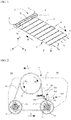
- the rewinder-unwinder device 1 of a protective tarpaulin 2 is a motorized device in the form of a gantry which moves in translation along the X axis above a surface 3 to be protected for deploy and remove the tarpaulin 2 without sliding it on said surface 3 and without rail on the ground S. It can be controlled by any appropriate control device, such as a wired control, a wireless control, a remote control, etc.
- the device 1 comprises a winding tube 4 extending along the Y axis perpendicular to the X axis, carried at its ends by two carriages 5, 6, a left carriage 5 and a right carriage 6 with reference to the figure 1 , provided with rolling means in contact with the ground S, and means (not shown) for driving the winding tube 4 in rotation and rolling means of the carriages 5, 6.
- the device 1 moves in translation along the X axis in a direction represented by the arrow D to unwind the tarpaulin 2 from the winding tube 4 and deploy it on the surface. 3, and in the opposite direction E to roll up the tarpaulin 2 on the winding tube 4 and remove it from the surface 3.
- the carriages 5, 6 have two functions: a "motor” function when they move the device 1 to unwind the tarpaulin 2 and a “follower” function when they are pulled by the device 1 to roll up the tarpaulin 2.
- the alternative movements of the device 1 are possible thanks to the mounting of the tarpaulin 2 between a fixed point on the ground S and a movable point linked to said device 1.
- one of the ends 2a of the tarpaulin 2 is fixed to the winding tube 4 by any suitable fixing means such as first straps 7 allowing it to wind on itself around said tube, and the opposite end 2b, also called extré apparent mity, is fixed to the ground S or to any fixed support, by any appropriate anchoring means such as second straps 8 linked to pegs 9 anchored in the ground S or in said fixed support.
- the fixed end 2b makes it possible to put the tarpaulin 2 under tension when it is wound up and to cause the device 1 to move in the direction E by pulling the tarpaulin itself. Any other compatible means of fixing or anchoring is possible.
- the cover 2 further comprises a plurality of transverse bars 10 to stiffen it when it is unrolled on the surface 3 to be protected and to ensure the safety of persons, in particular if the surface 3 is a basin of a swimming pool. It could also not include transverse bars in the case of other surfaces 3 to be protected.
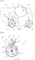
- the figures 2 to 6 illustrate a simplified and non-limiting example of a carriage 5 of the device 1.
- the two carriages 5 and 6 may or may not be identical, reversible or not, and interchangeable with one another or not.
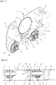
- the carriage 5 comprises a covered frame of which only two side flanges 11, 12 are shown. These flanges 11, 12 extend in substantially vertical planes, and are kept at a distance from each other by spacers 21 ( fig. 7 and 8 ) to define an interior space 13 receiving the drive means and the rolling means.
- the drive means are represented by a motor pinion 14 linked on the one hand to the winding tube 4 and on the other hand to a motor (not shown) or any other equivalent actuator, which can be electric, pneumatic, hydraulic or magnetic.
- the rolling means comprise two wheels 15, 16, a front wheel 15 and a rear wheel 16, preferably aligned on an axis X.
- the plane passing through the wheels 15 and 16 may have an angle zero or different from zero with the plane XZ (opening or pinching), the axes of rotation A of the wheels 15 and 16 remaining parallel to each other.
- the concepts relating to the front, front and rear rear are defined when the device 1 moves in the direction D corresponding to the unwinding of the tarpaulin 2.
- the two wheels 15 and 16 are driving.
- the drive means further comprise two receiving pinions 17, 18, each linked to a wheel 15, 16 and a power transmission in the form of a toothed belt 19, chain, or the like, which meshes the motor pinion 14 and the receiving pinions 17, 18 so that they all rotate in the same direction of rotation and at a constant speed of rotation.
- a tensioner 20 is provided on the path of the toothed belt 19 to ensure its meshing with the pinions 14, 17, 18 and automatically take up the operating play.
- the drive means are arranged to rotate in both directions of rotation, namely in a direction of rotation represented by arrows Rd corresponding to the direction D of unwinding of the tarpaulin 2 and in the opposite direction of rotation represented by arrows Re corresponding to the winding direction E of the tarpaulin 2.
- the rolling means may differ from this example and comprise a single driving wheel, more than two wheels per carriage, including one or more idle wheels, the wheels are not necessarily aligned on an X axis but offset, etc.
- the drive means may differ from this example and comprise a tubular electric motor installed in the winding tube 4, but also a motor directly coupled to one of the pinions 14.
- the drive means are common for the winding tube 4 and the driving wheel or wheels 15, 16 of the two carriages 5, 6, and comprise a single motor for the whole of the device 1.
- the drive means further comprise means clutch / disengagement to allow a speed difference between the drive pinion 14 and the slave pinions 17, 18.
- These clutch / disengagement means consist in particular of a freewheel (symbolized by three small arrows on the hub of each wheel 15, 16) arranged between each receiving pinion 17 , 18 and the hub of the corresponding wheel 15, 16, and / or between the winding tube 4 and the motor pinion 14, as described in the publication FR 2 893 651 A1 .
- the device 1 constitutes an improvement of the existing devices in that it comprises a braking system 100, 110 arranged to slow down or even block the rotation of at least one of the wheels 15, 16 of one or preferably of two carriages 5, 6, and cause additional tensioning of the tarpaulin 2 during its winding on said winding tube 4.
- the braking of the carriages 5, 6 has the technical effect of automatically re-centering the tarpaulin 2 on its axis of movement longitudinal perpendicular to the winding tube 4, to synchronize the speed of movement of the carriages 5, 6, and to position the transverse bars 10 parallel to each other and to the winding tube 4.
- the tarpaulin 2 is wound up parallel to itself and uniformly on the winding tube 4, the unbalance caused at each passage of a transverse bar 10 being automatically compensated by the braking of the carriages 5, 6 which move synchronously and homogeneous.
- the drive wheel or wheels 15, 16 of each carriage 5, 6 are designed to allow slipping between the hub of the wheel integral with a receiving pinion 17, 18 and its tread in contact with the ground S, as described in particular in the publication FR 2 893 651 A1 .
- the braking system 100, 110 which will be described has the advantage of being suitable or adapting to any type of rewinder-unwinder device corresponding to the preceding description, such as those which are the subject of the publications cited above.
- FR 2 893 651 A1 and FR 2 908 402 A1 or the one offered in a kit, subject of the patent application FR 3 084 095 A1 filed by the plaintiff.
- the preferred braking system 100, 110 is a mechanical system, simple in design, reliable, maintenance-free, without play take-up and inexpensive. It is designed to act on at least one of the wheels 15, 16 of the carriages 5, 6, outside the tire and its tread. Thus, the braking system is insensitive to the condition of the rolling surface on which the carriages 5, 6 move, and therefore to climatic conditions (rain making the rolling surface slippery, temperature variations modifying the hardness of the tire, etc. ..). In addition, being physically independent of the tire, it does not cause any wear to the tire and does not require any play take-up mechanism. This braking system 100, 110 is consequently less sensitive to wear, the friction force involved. on a couple of materials metal / plastic, or plastic / plastic, and not metal / rubber as in the publication WO 2014/060708 A1 .
- This braking system 100, 110 is particularly designed to adopt at least two positions, namely a passive position PP in a direction of rotation Rd of the drive means corresponding to the unwinding of the cover 2, and an active position PA in the direction of reverse rotation Re drive means corresponding to the winding of the tarpaulin 2, the passage from the passive position to the active position and vice versa of the braking system 100, 110 being generated automatically by the reversal of the direction of rotation of the drive means, therefore without any added mechanism.
- the braking system 100, 110 may be suitable.
- the figures 2 to 6 illustrate an all-or-nothing braking system 100
- the figures 7 to 10 illustrate a so-called adjustable braking system 110.
- An electromagnetic braking system (not described and not shown), active in the direction of rotation Re and passive (inactive) in the direction of rotation Rd, may also be suitable but has a cost and complexity of implementation greater than the solutions described. below.
- the braking system 100 is based on the principle of the pawl and the ratchet wheel which allows only one direction of rotation. It is put in place on each of the carriages 5, 6 to synchronize the braking between the left carriage 5 and the right carriage 6, and acts on at least one of the drive wheels 15, 16. More precisely, it comprises a movable pawl 101, integral with the carriage 5, and a ratchet wheel 102 integral with the wheel 15, so that in the direction of rotation Rd corresponding to the unwinding of the cover 2, the pawl 101 does not interact. not with the ratchet wheel 102 and the braking system 100 is in the passive position PP ( fig. 3 ), and in the reverse direction of rotation Re corresponding to the winding of the cover 2, the pawl 101 is engaged with the ratchet wheel 102 and the braking system 100 is in the active position PA ( fig. 4 ).
- the pawl 101 comprises a rigid lever, mounted on one of the flanges 11 of the carriage 5, free to rotate about an articulation axis 103 located above and to the right of the wheel 15 of the carriage 5, in order to be able to pivot freely from on either side of a vertical axis V passing through the articulation axis 103 and the axis of rotation A of the wheel 15.
- the rigid lever can be made of any undeformable material that is resistant to bending, such as for example hardened steel, aluminum, plastic material reinforced or not with composite fibers), or the like.
- the ratchet wheel 102 comprises a plurality of lugs 104, mounted on one of the sides of the wheel 15 to project from one side of the wheel 15, and regularly distributed in a concentric circle C around the axis A.
- the lugs 104 form the notches of the ratchet wheel 102. They are also made of any undeformable material and resistant to bending, such as for example hardened steel, aluminum, plastic material reinforced or not with composite fibers or similar .
- the pawl 101 adopts a neutral position in which it extends by gravity radially inside the ratchet wheel 102 between two lugs 104 on the vertical axis V passing through the axis of rotation A of the wheel 15.
- the braking system 100 further comprises a stop 105 fixed to the flange 11 of the carriage 5 in the environment close to the pawl 101 in order to lock it in the active position PA when it is in engagement with the wheel.
- ratchet 102 The stop 105 is disposed to the right of the vertical axis V passing through the articulation axis 103 to block the pawl 101 only in the direction of rotation Re of the ratchet wheel 102.
- the length of the pawl 101 must be greater than the distance between the hinge axis 103 at the circle C of the ratchet wheel 102 on the vertical axis V, so that the free end of the pawl 101 can penetrate inside the wheel at ratchet 102 between the lugs 104 and remain locked there when the pivoting of the pawl 101 is stopped by the stop 105 ( fig. 4 ).
- the length of the pawl 101 must also be less than the distance which separates the articulation axis 103 from the lug 104 located on the tangent to the circle C which passes through the articulation axis 103, opposite to the stop 105, so that the free end of the pawl 101 can escape the lugs 104 when the pivoting of the pawl 101 is not stopped by the stop 105 ( fig. 3 ).
- the braking system 110 is also based on the principle of the pawl and the ratchet wheel, but the retaining force of which is adjustable.
- the retaining force is different depending on the direction of rotation considered: it is stronger in the direction of rotation Re than in the direction of rotation Rd. It is placed on each of the carriages 5, 6 to synchronize the braking between the carriage 5 left and the carriage 6 right, and acts on at least one of the driving wheels 15, 16.
- pawl 111 integral with the carriage 5, and a ratchet wheel 112 integral with the wheel 15, so that in the direction of rotation Rd corresponding to the unwinding of the cover 2, the pawl 111 has a grip weaker with the ratchet wheel 112 and in the opposite direction of rotation Re corresponding to the winding of the tarpaulin 2, the pawl 111 has a stronger grip with the ratchet wheel 112.
- the pawl 111 comprises a flexible lever, and in the illustrated example of two parallel flexible levers, mounted on the carriage 5, at a fixed point 113 offset with respect to the vertical axis V passing through the axis of rotation A of the wheel 15 of the carriage 5 to extend more or less inside the ratchet wheel 112.
- the flexible lever may be made of any resilient material such as, for example, a spring steel blade, an elastomer blade, or the like.
- the ratchet wheel 112 comprises a plurality of lugs 114, mounted on the two flanks of the wheel 15 to be protruding on both sides of the wheel 15, and regularly distributed two concentric circles C around the axis A, likewise diameter to form two identical and parallel ratchet wheels 112.
- the lugs 114 form the notches of the ratchet wheel 112. They are made of any undeformable and bending-resistant material, such as for example hardened steel, aluminum, plastic material reinforced or not with composite fibers or the like. .
- the pawl 111 adopts a neutral position in which it extends along an axis more or less inclined with respect to the horizontal to penetrate more or less inside the ratchet wheels 112 between two lugs. 114.
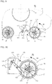
- the pawl 111 is mounted on a support 115 adjustable angularly relative to the circle C of the ratchet wheel 112, so that in the active position, the pawl 111 extends on a straight line which can be more or less tangent to said circle C ( fig. 10 ) offering minimal braking, or which intersects said circle C without passing through the axis of rotation A of wheel 15 ( fig. 9 ) providing maximum braking.
- the support 115 is fixed to the flange 11 of the carriage 5, directly or via a plate, by a ball screw 116 through positioning holes 117, or any other equivalent locking member.
- the holes 117 thus define a plurality of positions for adjusting the inclination of the pawl 111.
- the holes 117 are staggered on two concentric arcs of a circle.
- the ball screw 116 is actuated by hand and allows the fine adjustment of the angular position of the pawl 111 when the device 1 is first started up according to the actual situation and the tests carried out, in order to find the most suitable braking position. more satisfying.
- the figure 6 illustrates an example of a wheel 15, 16 of the carriages 5, 6 allowing a slipping effect when the braking system 100, 110 is in the active position.
- the wheel or wheels 15, 16 comprises or comprise a core 22 supporting a rim 23 comprising a tire 24 in contact with the ground S or any other rolling surface.
- the web 22 can slip on the rim 23 under the action of a sliding force arising from their difference in rotational speed. Skating makes it possible to compensate for their difference in speed, and to allow them to turn at a suitable speed.
- the core 22 is made of, or comprises, one or a mixture of plastic materials, of preferably polymeric, advantageously it is made of polyoxymethylene (POM).
- the rim 23 is made of, or comprises, one or a mixture of metals or alloys of metals. Preferably, it is made of stainless steel. The rim 23 could also be made of one or a mixture of plastic materials.
- the tire 24 is made, or comprises, one or a mixture of materials suitable for obtaining a strong adhesion of the wheel 15, 16 on the ground S promoting the slipping of the rim 23 on the web 22.
- the tire 24 is, for example example, made from elastomeric materials, such as natural rubbers, synthetic rubbers, EPDM rubbers, polyurethanes, and the like.
- the material of the tires 24 will be chosen from the family of EPDM type rubbers, exhibiting a low Shore hardness of for example between 40 and 70 ShA, and a high breaking strength of for example between 30 and 50 MPa. These values are indicative and not limitative.
- the various examples of materials cited are not, however, limiting, and any other material having equivalent characteristics may be suitable.
- a coefficient of friction between the web 22 and the rim 23 will be chosen which is lower than the coefficient of friction between the tire 24 and the ground S.
- the difference in the coefficient of friction between the web 22 and the rim 23 and the coefficient of friction between the tire 24 and the ground S can for example be between 0.05 and 0.5.
- the ratchet wheel 102, 112 of the braking system 100, 110 is advantageously integral with the web 22 of the wheel 15, 16.
Landscapes
- Engineering & Computer Science (AREA)
- Architecture (AREA)
- Civil Engineering (AREA)
- Structural Engineering (AREA)
- Tires In General (AREA)
- Braking Arrangements (AREA)
- Tents Or Canopies (AREA)
- Storing, Repeated Paying-Out, And Re-Storing Of Elongated Articles (AREA)
Priority Applications (1)
| Application Number | Priority Date | Filing Date | Title |
|---|---|---|---|
| PL20170303T PL3730724T3 (pl) | 2019-04-26 | 2020-04-20 | Urządzenie do nawijania i odwijania plandeki ochronnej |
Applications Claiming Priority (1)
| Application Number | Priority Date | Filing Date | Title |
|---|---|---|---|
| FR1904494A FR3095432B1 (fr) | 2019-04-26 | 2019-04-26 | Dispositif enrouleur-dérouleur d’une bâche de protection |
Publications (2)
| Publication Number | Publication Date |
|---|---|
| EP3730724A1 EP3730724A1 (fr) | 2020-10-28 |
| EP3730724B1 true EP3730724B1 (fr) | 2021-05-05 |
Family
ID=67441457
Family Applications (1)
| Application Number | Title | Priority Date | Filing Date |
|---|---|---|---|
| EP20170303.0A Active EP3730724B1 (fr) | 2019-04-26 | 2020-04-20 | Dispositif enrouleur-derouleur d'une bache de protection |
Country Status (6)
| Country | Link |
|---|---|
| US (1) | US11346120B2 (pl) |
| EP (1) | EP3730724B1 (pl) |
| ES (1) | ES2869556T3 (pl) |
| FR (1) | FR3095432B1 (pl) |
| PL (1) | PL3730724T3 (pl) |
| PT (1) | PT3730724T (pl) |
Cited By (1)
| Publication number | Priority date | Publication date | Assignee | Title |
|---|---|---|---|---|
| EP4589096A1 (fr) * | 2024-01-22 | 2025-07-23 | Becoflex | Dispositif de couverture d'une surface comprenant un mécanisme de translation longitudinale de tambour, muni d'un système d'embrayage |
Families Citing this family (2)
| Publication number | Priority date | Publication date | Assignee | Title |
|---|---|---|---|---|
| BE1027806B1 (fr) * | 2019-11-28 | 2021-06-28 | Becoflex | Dispositif de couverture d'une surface comprenant des moyens de verrouillage discrets |
| FR3137936B1 (fr) * | 2022-07-12 | 2024-06-21 | A S Pool | Système de recouvrement de bassin équipé d’un mécanisme de placage de couverture |
Family Cites Families (18)
| Publication number | Priority date | Publication date | Assignee | Title |
|---|---|---|---|---|
| US3050743A (en) * | 1961-08-07 | 1962-08-28 | Philip A Mallinckrodt | Extendible and retractable cover apparatus for swimming pools |
| US3747132A (en) * | 1972-05-12 | 1973-07-24 | E Foster | Swimming pool cover |
| US3982286A (en) * | 1974-10-15 | 1976-09-28 | Elton Gordon Foster | Swimming pool cover |
| US4195370A (en) * | 1978-09-12 | 1980-04-01 | Budd-Ke Enterprises, Inc. | Apparatus for reeling and unreeling pool covers |
| US4351072A (en) * | 1980-08-11 | 1982-09-28 | Automatic Solar Covers, Inc. | Semi-automatic pool cover |
| US4407027A (en) * | 1981-08-10 | 1983-10-04 | Colon Jr George M | Pool-cover apparatus and method |
| US4815152A (en) * | 1984-05-31 | 1989-03-28 | Macdonald Scott H | Pool cover movement limiting device |
| US4858253A (en) * | 1984-08-20 | 1989-08-22 | Lamb Joe H | Mechanism for extending and retracting swimming pool covers |
| US5524302A (en) * | 1984-08-20 | 1996-06-11 | Cover-Pools, Inc. | Method and apparatus of extending and retracting swimming pool covers |
| US6871362B1 (en) * | 2003-05-27 | 2005-03-29 | Lothar J Zell | Pool cover spool |
| FR2893651B1 (fr) | 2005-11-24 | 2009-07-10 | Philippe Richert | Enrouleur automatique de bache de protection |
| US7891031B2 (en) * | 2006-07-20 | 2011-02-22 | Belal Fathi Khalaf | Movable deck |
| FR2908402A1 (fr) | 2006-11-13 | 2008-05-16 | Hydroline Sa | Dispositif de manutention d'un element enroulable, installation pour couvrir et decouvrir un bassin de piscine et procede de deroulement et d'enroulement d'un element enroulable au-dessus d'une surface |
| EP2398565A1 (en) * | 2009-02-06 | 2011-12-28 | Textile Management Associates, Inc. | System and method for storage and temporary installation of secondary flooring surface |
| FR2997118B1 (fr) * | 2012-10-19 | 2014-12-12 | Ec2M | Dispositif a compensation pour recouvrir et decouvrir une surface par un element de couverture enroulable |
| BE1021653B1 (fr) * | 2012-11-05 | 2015-12-22 | Becoflex S.A. | Dispositif de couverture d'une surface comprenant un tambour mobile couvert d'un caisson de protection. |
| BE1023457B1 (fr) * | 2016-01-25 | 2017-03-27 | Becoflex S.A. | Dispositif de couverture d'une surface comprenant des moyens d'enclenchement |
| FR3084095B1 (fr) | 2018-07-18 | 2020-09-11 | Waterair | Kit pour dispositif de manutention d'un element enroulable souple |
-
2019
- 2019-04-26 FR FR1904494A patent/FR3095432B1/fr active Active
-
2020
- 2020-04-20 PT PT201703030T patent/PT3730724T/pt unknown
- 2020-04-20 ES ES20170303T patent/ES2869556T3/es active Active
- 2020-04-20 EP EP20170303.0A patent/EP3730724B1/fr active Active
- 2020-04-20 PL PL20170303T patent/PL3730724T3/pl unknown
- 2020-04-21 US US16/854,179 patent/US11346120B2/en active Active
Cited By (2)
| Publication number | Priority date | Publication date | Assignee | Title |
|---|---|---|---|---|
| EP4589096A1 (fr) * | 2024-01-22 | 2025-07-23 | Becoflex | Dispositif de couverture d'une surface comprenant un mécanisme de translation longitudinale de tambour, muni d'un système d'embrayage |
| BE1032349B1 (fr) * | 2024-01-22 | 2025-08-25 | Becoflex | Dispositif de couverture d’une surface comprenant un mécanisme de translation longitudinale de tambour, muni d’un système d’embrayage |
Also Published As
| Publication number | Publication date |
|---|---|
| FR3095432B1 (fr) | 2021-04-16 |
| US20200340262A1 (en) | 2020-10-29 |
| FR3095432A1 (fr) | 2020-10-30 |
| PL3730724T3 (pl) | 2021-08-23 |
| US11346120B2 (en) | 2022-05-31 |
| PT3730724T (pt) | 2021-06-01 |
| EP3730724A1 (fr) | 2020-10-28 |
| ES2869556T3 (es) | 2021-10-25 |
Similar Documents
| Publication | Publication Date | Title |
|---|---|---|
| BE1018228A3 (fr) | Dispositif de couverture d'une surface. | |
| EP3408470B1 (fr) | Dispositif de couverture d'une surface comprenant des moyens d'enclenchement | |
| EP3730724A1 (fr) | Dispositif enrouleur-derouleur d'une bache de protection | |
| EP1730365B1 (fr) | Dispositif a rideau deroulable | |
| FR2893651A1 (fr) | Enrouleur automatique de bache de protection | |
| EP2371592B1 (fr) | Store d'occultation pour véhicule automobile, à moyens anti-pincement | |
| EP3318700B1 (fr) | Chariot de support pour système de recouvrement de bassin | |
| FR2570119A1 (fr) | Dispositif de deroulement et d'enroulement d'une surface souple sur un tube | |
| FR2942426A1 (fr) | Procede et dispositifs permettant le deplacement d'un vehicule sur une surface glissante ou fragile | |
| FR3084095A1 (fr) | Kit pour dispositif de manutention d'un element enroulable souple | |
| EP4007836B1 (fr) | Dispositif de couverture d'une surface comprenant des moyens de verrouillage discrets | |
| FR3028543B1 (fr) | Enrouleur-derouleur pour une couverture de piscine | |
| EP4306745B1 (fr) | Chariot de support pour système de recouvrement de bassin | |
| BE1032349B1 (fr) | Dispositif de couverture d’une surface comprenant un mécanisme de translation longitudinale de tambour, muni d’un système d’embrayage | |
| BE1029655B1 (fr) | Dispositif compact de couverture d'une surface comprenant deux essieux pour le deploiement et le retrait de la couverture | |
| BE1030222B1 (fr) | Dispositif compact de couverture d'une surface comprenant un système de securite en cas de mauvais verrouillage de la couverture | |
| EP4033053B1 (fr) | Enrouleur-dérouleur automatique de bache au-dessus de la surface du bassin d'une piscine | |
| EP1637693B1 (fr) | Dispositif d'entraînement pour tablier de volet roulant | |
| EP1657398B1 (fr) | Dispositif d'entrainement pour tablier de volet roulant | |
| FR2754010A1 (fr) | Verrou pour volet roulant, equipe d'un axe d'enroulement du tablier libre en rotation | |
| FR2599421A1 (fr) | Volet roulant pour toit en pente et veranda. |
Legal Events
| Date | Code | Title | Description |
|---|---|---|---|
| PUAI | Public reference made under article 153(3) epc to a published international application that has entered the european phase |
Free format text: ORIGINAL CODE: 0009012 |
|
| STAA | Information on the status of an ep patent application or granted ep patent |
Free format text: STATUS: THE APPLICATION HAS BEEN PUBLISHED |
|
| AK | Designated contracting states |
Kind code of ref document: A1 Designated state(s): AL AT BE BG CH CY CZ DE DK EE ES FI FR GB GR HR HU IE IS IT LI LT LU LV MC MK MT NL NO PL PT RO RS SE SI SK SM TR |
|
| AX | Request for extension of the european patent |
Extension state: BA ME |
|
| STAA | Information on the status of an ep patent application or granted ep patent |
Free format text: STATUS: REQUEST FOR EXAMINATION WAS MADE |
|
| 17P | Request for examination filed |
Effective date: 20201112 |
|
| RBV | Designated contracting states (corrected) |
Designated state(s): AL AT BE BG CH CY CZ DE DK EE ES FI FR GB GR HR HU IE IS IT LI LT LU LV MC MK MT NL NO PL PT RO RS SE SI SK SM TR |
|
| GRAP | Despatch of communication of intention to grant a patent |
Free format text: ORIGINAL CODE: EPIDOSNIGR1 |
|
| STAA | Information on the status of an ep patent application or granted ep patent |
Free format text: STATUS: GRANT OF PATENT IS INTENDED |
|
| RIC1 | Information provided on ipc code assigned before grant |
Ipc: A63C 19/12 20060101ALI20201214BHEP Ipc: E04H 4/10 20060101AFI20201214BHEP |
|
| INTG | Intention to grant announced |
Effective date: 20210114 |
|
| GRAS | Grant fee paid |
Free format text: ORIGINAL CODE: EPIDOSNIGR3 |
|
| GRAA | (expected) grant |
Free format text: ORIGINAL CODE: 0009210 |
|
| STAA | Information on the status of an ep patent application or granted ep patent |
Free format text: STATUS: THE PATENT HAS BEEN GRANTED |
|
| AK | Designated contracting states |
Kind code of ref document: B1 Designated state(s): AL AT BE BG CH CY CZ DE DK EE ES FI FR GB GR HR HU IE IS IT LI LT LU LV MC MK MT NL NO PL PT RO RS SE SI SK SM TR |
|
| REG | Reference to a national code |
Ref country code: GB Ref legal event code: FG4D Free format text: NOT ENGLISH |
|
| REG | Reference to a national code |
Ref country code: NL Ref legal event code: FP |
|
| REG | Reference to a national code |
Ref country code: CH Ref legal event code: EP |
|
| REG | Reference to a national code |
Ref country code: AT Ref legal event code: REF Ref document number: 1389991 Country of ref document: AT Kind code of ref document: T Effective date: 20210515 |
|
| REG | Reference to a national code |
Ref country code: IE Ref legal event code: FG4D Free format text: LANGUAGE OF EP DOCUMENT: FRENCH |
|
| REG | Reference to a national code |
Ref country code: DE Ref legal event code: R096 Ref document number: 602020000085 Country of ref document: DE |
|
| REG | Reference to a national code |
Ref country code: PT Ref legal event code: SC4A Ref document number: 3730724 Country of ref document: PT Date of ref document: 20210601 Kind code of ref document: T Free format text: AVAILABILITY OF NATIONAL TRANSLATION Effective date: 20210506 |
|
| REG | Reference to a national code |
Ref country code: LT Ref legal event code: MG9D |
|
| REG | Reference to a national code |
Ref country code: AT Ref legal event code: MK05 Ref document number: 1389991 Country of ref document: AT Kind code of ref document: T Effective date: 20210505 |
|
| REG | Reference to a national code |
Ref country code: ES Ref legal event code: FG2A Ref document number: 2869556 Country of ref document: ES Kind code of ref document: T3 Effective date: 20211025 |
|
| PG25 | Lapsed in a contracting state [announced via postgrant information from national office to epo] |
Ref country code: BG Free format text: LAPSE BECAUSE OF FAILURE TO SUBMIT A TRANSLATION OF THE DESCRIPTION OR TO PAY THE FEE WITHIN THE PRESCRIBED TIME-LIMIT Effective date: 20210805 Ref country code: AT Free format text: LAPSE BECAUSE OF FAILURE TO SUBMIT A TRANSLATION OF THE DESCRIPTION OR TO PAY THE FEE WITHIN THE PRESCRIBED TIME-LIMIT Effective date: 20210505 Ref country code: LT Free format text: LAPSE BECAUSE OF FAILURE TO SUBMIT A TRANSLATION OF THE DESCRIPTION OR TO PAY THE FEE WITHIN THE PRESCRIBED TIME-LIMIT Effective date: 20210505 Ref country code: HR Free format text: LAPSE BECAUSE OF FAILURE TO SUBMIT A TRANSLATION OF THE DESCRIPTION OR TO PAY THE FEE WITHIN THE PRESCRIBED TIME-LIMIT Effective date: 20210505 Ref country code: FI Free format text: LAPSE BECAUSE OF FAILURE TO SUBMIT A TRANSLATION OF THE DESCRIPTION OR TO PAY THE FEE WITHIN THE PRESCRIBED TIME-LIMIT Effective date: 20210505 |
|
| PG25 | Lapsed in a contracting state [announced via postgrant information from national office to epo] |
Ref country code: IS Free format text: LAPSE BECAUSE OF FAILURE TO SUBMIT A TRANSLATION OF THE DESCRIPTION OR TO PAY THE FEE WITHIN THE PRESCRIBED TIME-LIMIT Effective date: 20210905 Ref country code: GR Free format text: LAPSE BECAUSE OF FAILURE TO SUBMIT A TRANSLATION OF THE DESCRIPTION OR TO PAY THE FEE WITHIN THE PRESCRIBED TIME-LIMIT Effective date: 20210806 Ref country code: RS Free format text: LAPSE BECAUSE OF FAILURE TO SUBMIT A TRANSLATION OF THE DESCRIPTION OR TO PAY THE FEE WITHIN THE PRESCRIBED TIME-LIMIT Effective date: 20210505 Ref country code: SE Free format text: LAPSE BECAUSE OF FAILURE TO SUBMIT A TRANSLATION OF THE DESCRIPTION OR TO PAY THE FEE WITHIN THE PRESCRIBED TIME-LIMIT Effective date: 20210505 Ref country code: NO Free format text: LAPSE BECAUSE OF FAILURE TO SUBMIT A TRANSLATION OF THE DESCRIPTION OR TO PAY THE FEE WITHIN THE PRESCRIBED TIME-LIMIT Effective date: 20210805 Ref country code: LV Free format text: LAPSE BECAUSE OF FAILURE TO SUBMIT A TRANSLATION OF THE DESCRIPTION OR TO PAY THE FEE WITHIN THE PRESCRIBED TIME-LIMIT Effective date: 20210505 |
|
| PG25 | Lapsed in a contracting state [announced via postgrant information from national office to epo] |
Ref country code: EE Free format text: LAPSE BECAUSE OF FAILURE TO SUBMIT A TRANSLATION OF THE DESCRIPTION OR TO PAY THE FEE WITHIN THE PRESCRIBED TIME-LIMIT Effective date: 20210505 Ref country code: SK Free format text: LAPSE BECAUSE OF FAILURE TO SUBMIT A TRANSLATION OF THE DESCRIPTION OR TO PAY THE FEE WITHIN THE PRESCRIBED TIME-LIMIT Effective date: 20210505 Ref country code: DK Free format text: LAPSE BECAUSE OF FAILURE TO SUBMIT A TRANSLATION OF THE DESCRIPTION OR TO PAY THE FEE WITHIN THE PRESCRIBED TIME-LIMIT Effective date: 20210505 Ref country code: SM Free format text: LAPSE BECAUSE OF FAILURE TO SUBMIT A TRANSLATION OF THE DESCRIPTION OR TO PAY THE FEE WITHIN THE PRESCRIBED TIME-LIMIT Effective date: 20210505 Ref country code: RO Free format text: LAPSE BECAUSE OF FAILURE TO SUBMIT A TRANSLATION OF THE DESCRIPTION OR TO PAY THE FEE WITHIN THE PRESCRIBED TIME-LIMIT Effective date: 20210505 |
|
| REG | Reference to a national code |
Ref country code: DE Ref legal event code: R097 Ref document number: 602020000085 Country of ref document: DE |
|
| PLBE | No opposition filed within time limit |
Free format text: ORIGINAL CODE: 0009261 |
|
| STAA | Information on the status of an ep patent application or granted ep patent |
Free format text: STATUS: NO OPPOSITION FILED WITHIN TIME LIMIT |
|
| 26N | No opposition filed |
Effective date: 20220208 |
|
| PG25 | Lapsed in a contracting state [announced via postgrant information from national office to epo] |
Ref country code: IS Free format text: LAPSE BECAUSE OF FAILURE TO SUBMIT A TRANSLATION OF THE DESCRIPTION OR TO PAY THE FEE WITHIN THE PRESCRIBED TIME-LIMIT Effective date: 20210905 Ref country code: AL Free format text: LAPSE BECAUSE OF FAILURE TO SUBMIT A TRANSLATION OF THE DESCRIPTION OR TO PAY THE FEE WITHIN THE PRESCRIBED TIME-LIMIT Effective date: 20210505 |
|
| PG25 | Lapsed in a contracting state [announced via postgrant information from national office to epo] |
Ref country code: MC Free format text: LAPSE BECAUSE OF FAILURE TO SUBMIT A TRANSLATION OF THE DESCRIPTION OR TO PAY THE FEE WITHIN THE PRESCRIBED TIME-LIMIT Effective date: 20210505 |
|
| PG25 | Lapsed in a contracting state [announced via postgrant information from national office to epo] |
Ref country code: IE Free format text: LAPSE BECAUSE OF NON-PAYMENT OF DUE FEES Effective date: 20220420 |
|
| P01 | Opt-out of the competence of the unified patent court (upc) registered |
Effective date: 20230527 |
|
| PGFP | Annual fee paid to national office [announced via postgrant information from national office to epo] |
Ref country code: LU Payment date: 20240325 Year of fee payment: 5 Ref country code: NL Payment date: 20240325 Year of fee payment: 5 |
|
| PG25 | Lapsed in a contracting state [announced via postgrant information from national office to epo] |
Ref country code: MK Free format text: LAPSE BECAUSE OF FAILURE TO SUBMIT A TRANSLATION OF THE DESCRIPTION OR TO PAY THE FEE WITHIN THE PRESCRIBED TIME-LIMIT Effective date: 20210505 Ref country code: CY Free format text: LAPSE BECAUSE OF FAILURE TO SUBMIT A TRANSLATION OF THE DESCRIPTION OR TO PAY THE FEE WITHIN THE PRESCRIBED TIME-LIMIT Effective date: 20210505 |
|
| PGFP | Annual fee paid to national office [announced via postgrant information from national office to epo] |
Ref country code: CZ Payment date: 20240319 Year of fee payment: 5 Ref country code: PT Payment date: 20240318 Year of fee payment: 5 |
|
| PG25 | Lapsed in a contracting state [announced via postgrant information from national office to epo] |
Ref country code: HU Free format text: LAPSE BECAUSE OF FAILURE TO SUBMIT A TRANSLATION OF THE DESCRIPTION OR TO PAY THE FEE WITHIN THE PRESCRIBED TIME-LIMIT; INVALID AB INITIO Effective date: 20200420 |
|
| PGFP | Annual fee paid to national office [announced via postgrant information from national office to epo] |
Ref country code: PL Payment date: 20240320 Year of fee payment: 5 |
|
| PGFP | Annual fee paid to national office [announced via postgrant information from national office to epo] |
Ref country code: GB Payment date: 20240425 Year of fee payment: 5 |
|
| PGFP | Annual fee paid to national office [announced via postgrant information from national office to epo] |
Ref country code: ES Payment date: 20240506 Year of fee payment: 5 |
|
| PGFP | Annual fee paid to national office [announced via postgrant information from national office to epo] |
Ref country code: IT Payment date: 20240409 Year of fee payment: 5 |
|
| PGFP | Annual fee paid to national office [announced via postgrant information from national office to epo] |
Ref country code: BE Payment date: 20240415 Year of fee payment: 5 |
|
| PG25 | Lapsed in a contracting state [announced via postgrant information from national office to epo] |
Ref country code: MT Free format text: LAPSE BECAUSE OF FAILURE TO SUBMIT A TRANSLATION OF THE DESCRIPTION OR TO PAY THE FEE WITHIN THE PRESCRIBED TIME-LIMIT Effective date: 20210505 |
|
| PGFP | Annual fee paid to national office [announced via postgrant information from national office to epo] |
Ref country code: DE Payment date: 20250411 Year of fee payment: 6 |
|
| PGFP | Annual fee paid to national office [announced via postgrant information from national office to epo] |
Ref country code: FR Payment date: 20250423 Year of fee payment: 6 |
|
| PGFP | Annual fee paid to national office [announced via postgrant information from national office to epo] |
Ref country code: CH Payment date: 20250501 Year of fee payment: 6 |
|
| REG | Reference to a national code |
Ref country code: NL Ref legal event code: MM Effective date: 20250501 |
|
| PG25 | Lapsed in a contracting state [announced via postgrant information from national office to epo] |
Ref country code: PT Free format text: LAPSE BECAUSE OF NON-PAYMENT OF DUE FEES Effective date: 20251020 |
|
| PG25 | Lapsed in a contracting state [announced via postgrant information from national office to epo] |
Ref country code: TR Free format text: LAPSE BECAUSE OF FAILURE TO SUBMIT A TRANSLATION OF THE DESCRIPTION OR TO PAY THE FEE WITHIN THE PRESCRIBED TIME-LIMIT Effective date: 20210505 |
|
| PG25 | Lapsed in a contracting state [announced via postgrant information from national office to epo] |
Ref country code: LU Free format text: LAPSE BECAUSE OF NON-PAYMENT OF DUE FEES Effective date: 20250420 |
|
| GBPC | Gb: european patent ceased through non-payment of renewal fee |
Effective date: 20250420 |
|
| REG | Reference to a national code |
Ref country code: BE Ref legal event code: MM Effective date: 20250430 |
|
| PG25 | Lapsed in a contracting state [announced via postgrant information from national office to epo] |
Ref country code: GB Free format text: LAPSE BECAUSE OF NON-PAYMENT OF DUE FEES Effective date: 20250420 |
|
| PG25 | Lapsed in a contracting state [announced via postgrant information from national office to epo] |
Ref country code: NL Free format text: LAPSE BECAUSE OF NON-PAYMENT OF DUE FEES Effective date: 20250501 |
|
| PG25 | Lapsed in a contracting state [announced via postgrant information from national office to epo] |
Ref country code: BE Free format text: LAPSE BECAUSE OF NON-PAYMENT OF DUE FEES Effective date: 20250430 |
|
| PG25 | Lapsed in a contracting state [announced via postgrant information from national office to epo] |
Ref country code: CZ Free format text: LAPSE BECAUSE OF NON-PAYMENT OF DUE FEES Effective date: 20250420 |
|
| REG | Reference to a national code |
Ref country code: DE Ref legal event code: R082 Ref document number: 602020000085 Country of ref document: DE Representative=s name: VUILLERMOZ, BRUNO, FR |
|
| PG25 | Lapsed in a contracting state [announced via postgrant information from national office to epo] |
Ref country code: IT Free format text: LAPSE BECAUSE OF NON-PAYMENT OF DUE FEES Effective date: 20250420 |
|
| PG25 | Lapsed in a contracting state [announced via postgrant information from national office to epo] |
Ref country code: PL Free format text: LAPSE BECAUSE OF NON-PAYMENT OF DUE FEES Effective date: 20250420 |