EP3730436A1 - Yarn winding machine and yarn threading method - Google Patents

Yarn winding machine and yarn threading method Download PDF

Info

Publication number
EP3730436A1
EP3730436A1 EP20169911.3A EP20169911A EP3730436A1 EP 3730436 A1 EP3730436 A1 EP 3730436A1 EP 20169911 A EP20169911 A EP 20169911A EP 3730436 A1 EP3730436 A1 EP 3730436A1
Authority
EP
European Patent Office
Prior art keywords
bobbin
yarn
pair
holders
detected
Prior art date
Legal status (The legal status is an assumption and is not a legal conclusion. Google has not performed a legal analysis and makes no representation as to the accuracy of the status listed.)
Withdrawn
Application number
EP20169911.3A
Other languages
German (de)
French (fr)
Inventor
Kenichi Ueda
Current Assignee (The listed assignees may be inaccurate. Google has not performed a legal analysis and makes no representation or warranty as to the accuracy of the list.)
Murata Machinery Ltd
Original Assignee
Murata Machinery Ltd
Priority date (The priority date is an assumption and is not a legal conclusion. Google has not performed a legal analysis and makes no representation as to the accuracy of the date listed.)
Filing date
Publication date
Application filed by Murata Machinery Ltd filed Critical Murata Machinery Ltd
Publication of EP3730436A1 publication Critical patent/EP3730436A1/en
Withdrawn legal-status Critical Current

Links

Images

Classifications

    • BPERFORMING OPERATIONS; TRANSPORTING
    • B65CONVEYING; PACKING; STORING; HANDLING THIN OR FILAMENTARY MATERIAL
    • B65HHANDLING THIN OR FILAMENTARY MATERIAL, e.g. SHEETS, WEBS, CABLES
    • B65H67/00Replacing or removing cores, receptacles, or completed packages at paying-out, winding, or depositing stations
    • B65H67/04Arrangements for removing completed take-up packages and or replacing by cores, formers, or empty receptacles at winding or depositing stations; Transferring material between adjacent full and empty take-up elements
    • B65H67/0405Arrangements for removing completed take-up packages or for loading an empty core
    • B65H67/0417Arrangements for removing completed take-up packages or for loading an empty core for loading an empty core
    • BPERFORMING OPERATIONS; TRANSPORTING
    • B65CONVEYING; PACKING; STORING; HANDLING THIN OR FILAMENTARY MATERIAL
    • B65HHANDLING THIN OR FILAMENTARY MATERIAL, e.g. SHEETS, WEBS, CABLES
    • B65H54/00Winding, coiling, or depositing filamentary material
    • B65H54/02Winding and traversing material on to reels, bobbins, tubes, or like package cores or formers
    • B65H54/10Winding and traversing material on to reels, bobbins, tubes, or like package cores or formers for making packages of specified shapes or on specified types of bobbins, tubes, cores, or formers
    • BPERFORMING OPERATIONS; TRANSPORTING
    • B65CONVEYING; PACKING; STORING; HANDLING THIN OR FILAMENTARY MATERIAL
    • B65HHANDLING THIN OR FILAMENTARY MATERIAL, e.g. SHEETS, WEBS, CABLES
    • B65H54/00Winding, coiling, or depositing filamentary material
    • B65H54/02Winding and traversing material on to reels, bobbins, tubes, or like package cores or formers
    • B65H54/28Traversing devices; Package-shaping arrangements
    • BPERFORMING OPERATIONS; TRANSPORTING
    • B65CONVEYING; PACKING; STORING; HANDLING THIN OR FILAMENTARY MATERIAL
    • B65HHANDLING THIN OR FILAMENTARY MATERIAL, e.g. SHEETS, WEBS, CABLES
    • B65H54/00Winding, coiling, or depositing filamentary material
    • B65H54/70Other constructional features of yarn-winding machines
    • B65H54/72Framework; Casings; Coverings
    • BPERFORMING OPERATIONS; TRANSPORTING
    • B65CONVEYING; PACKING; STORING; HANDLING THIN OR FILAMENTARY MATERIAL
    • B65HHANDLING THIN OR FILAMENTARY MATERIAL, e.g. SHEETS, WEBS, CABLES
    • B65H54/00Winding, coiling, or depositing filamentary material
    • B65H54/86Arrangements for taking-up waste material before or after winding or depositing
    • B65H54/88Arrangements for taking-up waste material before or after winding or depositing by means of pneumatic arrangements, e.g. suction guns
    • BPERFORMING OPERATIONS; TRANSPORTING
    • B65CONVEYING; PACKING; STORING; HANDLING THIN OR FILAMENTARY MATERIAL
    • B65HHANDLING THIN OR FILAMENTARY MATERIAL, e.g. SHEETS, WEBS, CABLES
    • B65H65/00Securing material to cores or formers
    • BPERFORMING OPERATIONS; TRANSPORTING
    • B65CONVEYING; PACKING; STORING; HANDLING THIN OR FILAMENTARY MATERIAL
    • B65HHANDLING THIN OR FILAMENTARY MATERIAL, e.g. SHEETS, WEBS, CABLES
    • B65H2701/00Handled material; Storage means
    • B65H2701/30Handled filamentary material
    • B65H2701/31Textiles threads or artificial strands of filaments

Definitions

  • the present disclosure relates to a yarn winding machine and a yarn threading method.
  • a supply device provided to the doffing carrier may supply a bobbin to a pair of bobbin holders provided to the winding device, and also, a yarn threading device provided to the doffing carrier may thread yarn onto the bobbin (see Japanese Unexamined Patent Publication No. 2006-225092 , for example).
  • a yarn winding machine includes: a winding device including a pair of bobbin holders configured to hold a bobbin and a cradle configured to support the pair of bobbin holders; an operating device configured to operate the cradle to open and close the pair of bobbin holders; a supply device configured to supply the bobbin to the pair of bobbin holders; a yarn threading device configured to catch yarn and thread the yarn onto the bobbin; and a control unit configured to control the operating device, the supply device, and the yarn threading device.
  • the control unit is configured to perform a first control when a first-type error that occurs after a catching operation of the yarn threading device to catch the yarn has been detected in a state in which a first bobbin as the bobbin has been supplied to the pair of bobbin holders, the first control performed to control the operating device, the supply device, and the yarn threading device such that the first bobbin is discharged from the pair of bobbin holders, a second bobbin as the bobbin is supplied to the pair of bobbin holders, and the yarn is threaded onto the second bobbin.
  • the control unit is configured to perform a second control when a second-type error that occurs before the catching operation or during the catching operation has been detected in a state in which the first bobbin has been supplied to the pair of bobbin holders, the second control performed to control the operating device, the supply device, and the yarn threading device such that the yarn is threaded onto the first bobbin while the state in which the first bobbin has been supplied to the pair of bobbin holders is being maintained.
  • the bobbin can be replaced without intervention of an operator, and this replacement of the bobbin can prevent a package, including unnecessary yarn, from being formed. Furthermore, when the second-type error that occurs before the catching operation of the yarn threading device to catch yarn or during the catching operation has been detected, yarn is threaded onto the first bobbin while the state in which the first bobbin has been supplied to the pair of bobbin holders is being maintained, because unnecessary yarn is less likely to have been wound around the first bobbin that has been supplied to the pair of bobbin holders. Thus, a period of time required for recovery from the error can be shortened by a period of time required for replacing the bobbin.
  • the yarn winding machine may further include: a bobbin collection section configured to collect the first bobbin discharged from the pair of bobbin holders when the first-type error has been detected; and a bobbin holding device configured to hold the second bobbin to be supplied to the pair of bobbin holders when the first-type error has been detected.
  • the supply device may be configured to receive the first bobbin from the pair of bobbin holders and pass the first bobbin to the bobbin collection section, and to receive the second bobbin from the bobbin holding device and pass the second bobbin to the pair of bobbin holders, when the first-type error has been detected. This eliminates the need to provide a device configured to receive the first bobbin from the pair of bobbin holders and pass the first bobbin to the bobbin collection section in addition to the supply device, and thus, the configuration can be simplified.
  • the supply device may include a clamping unit configured to clamp the bobbin, and may be configured such that the clamping unit is movable between a first position and a second position, and the clamping unit is movable between the first position and a third position.
  • the first position is a standby position of the clamping unit
  • the second position is a position for passing the bobbin to the pair of bobbin holders and receiving the bobbin from the pair of bobbin holders
  • the third position is a position for passing the bobbin to the bobbin collection section.
  • the bobbin holding device may be configured to be movable between a fourth position and a fifth position.
  • the fourth position is a position on a track of the clamping unit between the first position and the second position
  • the fifth position is a position off the track of the clamping unit between the first position and the second position.
  • the track of the clamping unit between the first position and the third position may pass through an area above the fourth position and the fifth position in a height direction.
  • the bobbin collection section may comprise a conveyor configured to convey the first bobbin.
  • the first bobbin can be automatically conveyed to a predetermined location.
  • the bobbin collection section may comprise a stocker configured to store the first bobbin.
  • the first bobbin can be collected without using the conveyor or the like, and the first bobbin stored in the stocker can be automatically discharged to a collection box, for example, provided in a predetermined location or can be collected by the operator.
  • the yarn winding machine may further include: a first sensor configured to detect whether the yarn has been caught by the yarn threading device; and a second sensor configured to detect whether the yarn is being wound by the winding device.
  • the control unit may be configured to perform the first control when the first sensor has detected that the yarn has been caught and then the second sensor has detected that the yarn is not being wound, as being a case where the first-type error has been detected.
  • unnecessary yarn is more likely to have been wound around the first bobbin that has been supplied to the pair of bobbin holders.
  • the bobbin can be replaced without intervention of the operator, and this replacement of the bobbin can prevent a package including unnecessary yarn from being formed.
  • the yarn winding machine may further include: an air spinning device configured to twist a fiber bundle using swirling airflow to form the yarn; and a third sensor configured to detect whether the yarn has been spun out from the air spinning device.
  • the control unit may be configured to perform the second control when the third sensor has detected that the yarn has not been spun out, as being a case where the second-type error has been detected.
  • unnecessary yarn is less likely to have been wound around the first bobbin that has been supplied to the pair of bobbin holders.
  • control unit may be configured to perform the second control when the third sensor has detected that the yarn has been spun out and then the first sensor has detected that the yarn has not been caught, as being the case where the second-type error has been detected.
  • the third sensor has detected that the yarn has been spun out and then the first sensor has detected that the yarn has not been caught, unnecessary yarn is less likely to have been wound around the first bobbin that has been supplied to the pair of bobbin holders.
  • a period of time required for recovery from the error can be shortened by a period of time required for replacing the bobbin.
  • the winding device may be disposed at a position for winding the yarn traveling upward from a lower side.
  • a yarn threading method is a yarn threading method that is performed in a yarn winding machine including: a winding device including a pair of bobbin holders configured to hold a bobbin and a cradle configured to support the pair of bobbin holders; an operating device configured to operate the cradle to open and close the pair of bobbin holders; a supply device configured to supply the bobbin to the pair of bobbin holders; and a yarn threading device configured to catch yarn and thread the yarn onto the bobbin.
  • the yarn threading method includes: a step of, when a first-type error that occurs after catching operation of the yarn threading device to catch the yarn has been detected in a state in which a first bobbin as the bobbin has been supplied to the pair of bobbin holders, discharging the first bobbin from the pair of bobbin holders, supplying a second bobbin as the bobbin to the pair of bobbin holders, and threading the yarn onto the second bobbin; and a step of, when a second-type error that occurs before the catching operation or during the catching operation has been detected in a state in which the first bobbin has been supplied to the pair of bobbin holders, threading the yarn onto the first bobbin while maintaining the state in which the first bobbin has been supplied to the pair of bobbin holders.
  • a spinning machine (yarn winding machine) 1 includes a plurality of spinning units (yarn winding units) 2, a doffing carrier 10, and a control unit 100.
  • the spinning units 2 are aligned in a row.
  • Each spinning unit 2 drafts a sliver (fiber bundle) S to form a fiber bundle F, twists the fiber bundle F using swirling airflow to form yarn Y, and winds the yarn Y around a bobbin B to form a package P.
  • the doffing carrier 10 is movable along a direction in which the spinning units 2 are aligned.
  • the control unit 100 controls operation of the spinning machine 1.
  • the control unit 100 is configured with a machine control device and a plurality of unit controllers, for example.
  • the machine control device is a host controller of the unit controllers.
  • Each unit controller is provided for every predetermined number of (one or more) spinning units 2, and controls operation of each spinning unit 2.
  • upstream side the upstream side of the sliver S, the fiber bundle F, and the yarn Y in their traveling direction
  • downstream side in the traveling direction is called “downstream side”.
  • One side in a horizontal direction orthogonal to the direction in which the spinning units 2 are aligned is called “front side”
  • rear side the other side in the horizontal direction
  • the upper side in the vertical direction is called “upper side”
  • the lower side in the vertical direction is called “lower side”.
  • Each spinning unit 2 includes, in the order from the upstream side toward the downstream side, a drafting device 3, an air spinning device 4, a yarn monitoring device 5, a yarn storage device 6, a yarn joining device 7, and a winding device 20.
  • the spinning unit 2 further includes a first catching-and-guiding device 8 and a second catching-and-guiding device 9.
  • the traveling direction of the sliver S, the fiber bundle F, and the yarn Y from the drafting device 3 to the yarn storage device 6 is a direction extending from the front side toward the rear side, and is inclined upward with respect to the horizontal direction.
  • the traveling direction of the yarn Y from the yarn storage device 6 to the winding device 20 is a direction extending from the lower side toward the upper side, and is inclined forward with respect to the vertical direction. In each spinning unit 2, the traveling direction of the yarn Y is turned at the yarn storage device 6.
  • the drafting device 3 drafts the sliver S to form the fiber bundle F, and feeds the fiber bundle F to the air spinning device 4.
  • the drafting device 3 includes a plurality of roller pairs aligned from the upstream side toward the downstream side and apron belts wound around the respective rollers of a predetermined roller pair.
  • the air spinning device 4 twists the fiber bundle F from the drafting device 3 using swirling airflow to form the yarn Y.
  • the yarn monitoring device 5 monitors information on traveling the yarn Y to detect the presence or absence of a yarn defect on the basis of the monitored information.
  • the yarn monitoring device 5 transmits a yarn-defect detection signal to the control unit 100.
  • the control unit 100 causes the drafting device 3 and the air spinning device 4 to stop operating such that supply of the yarn Y is stopped.
  • the control unit 100 may cause a cutter provided to the yarn monitoring device 5, for example, to operate.
  • the yarn storage device 6 includes a yarn storage roller 61 and a yarn hooking member 62.
  • the yarn storage roller 61 is rotated by an electric motor (not illustrated).
  • the yarn hooking member 62 is attached to a downstream end portion of the yarn storage roller 61, and is rotatable relative to the yarn storage roller 61.
  • magnetic force that interferes with rotation relative to the yarn storage roller 61 acts on the yarn hooking member 62.
  • the yarn hooking member 62 rotates together with the yarn storage roller 61, whereby the yarn Y is wound (stored) around the yarn storage roller 61.
  • the yarn hooking member 62 rotates relative to the yarn storage roller 61, whereby the yarn Y is unwound from the yarn storage roller 61.
  • the yarn storage device 6 stores the yarn Y in this manner, thereby absorbing variation in tension applied to the yarn Y on the downstream side of the yarn storage device 6, and stably drawing out the yarn Y from the air spinning device 4.
  • a first guide 63 is disposed on the upstream side of the yarn storage device 6.
  • the first guide 63 guides the yarn Y traveling from the upstream side to the yarn storage device 6.
  • the first guide 63 is movable, and draws the yarn Y from the air spinning device 4 toward the yarn storage device 6 when yarn joining is performed, for example.
  • a second guide 64, a third guide 65, and a fourth guide 66 are disposed on the downstream side of the yarn storage device 6.
  • the second guide 64 and the third guide 65 guide the yarn Y traveling from the yarn storage device 6 to the downstream side.
  • the second guide 64 is movable, and can guide the yarn Y to the third guide 65.
  • the fourth guide 66 is movable, and hooks the yarn Y onto the yarn hooking member 62 and unhooks the yarn Y from the yarn hooking member 62.
  • the yarn joining device 7 joins the yarn Y from the air spinning device 4 and the yarn Y from a package P.
  • the yarn joining device 7 is a splicer device configured to twist yarn ends together using swirling airflow.
  • the yarn joining device 7 may be a mechanical knotter, for example.
  • Each of the first catching-and-guiding device 8 and the second catching-and-guiding device 9 is swingable about its base-end portion.
  • the first catching-and-guiding device 8 swings downward to catch the yarn Y from the air spinning device 4 using suction airflow, and then swings upward to guide the yarn Y from the air spinning device 4 to the yarn joining device 7.
  • the second catching-and-guiding device 9 swings upward to catch the yarn Y from the package P using suction airflow, and then swings downward to guide the yarn Y from the package P to the yarn joining device 7.
  • the winding device 20 winds the yarn Y, drawn out by the yarn storage device 6, around a bobbin B to form a package P.
  • the winding device 20 includes a drum 23, a first bobbin holder 21 and a second bobbin holder 22 as a pair of bobbin holders, and a cradle 24.
  • a fifth guide 26 is disposed on the upstream side of the winding device 20.
  • the fifth guide 26 guides the yarn Y traveling from the upstream side to the drum 23.
  • an empty bobbin B around which the yarn Y is not wound is illustrated in Fig. 2
  • the respective components of the winding device 20 function in the same manner also for a package P (see Fig. 1 ) with the yarn Y wound around the bobbin B.
  • the drum 23 rotates the bobbin B while making contact with the bobbin B.
  • the drum 23 rotates the package P while being in contact with the package P.
  • the drum 23 is rotatably supported by the frame 25, and is rotated about a rotation axis L1 by a drum driving section (not illustrated) provided to each spinning unit 2.
  • each spinning unit 2 includes the drum driving section configured to drive the drum 23.
  • a traverse groove (not illustrated) is formed on a surface of the drum 23, a traverse groove (not illustrated) is formed. By this traverse groove, the yarn Y is traversed when the yarn Y is wound around the bobbin B.
  • the yarn Y may be traversed by an additionally provided traversing device when the yarn Y is wound around the bobbin B.
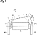
  • the first bobbin holder 21 holds an end portion B1 of the bobbin B
  • the second bobbin holder 22 holds an end portion B2 of the bobbin B.
  • the pair of bobbin holders 21, 22 holds both end portions of the bobbin B in this manner, thereby holding the bobbin B.
  • the cradle 24 rotatably supports the pair of bobbin holders 21, 22 in a manner that the pair of bobbin holders 21, 22 can be opened and closed and the pair of bobbin holders 21, 22 can be moved with respect to the drum 23.
  • the cradle 24 is swingable about a swinging axis L2.
  • the cradle 24 swings about the swinging axis L2, thereby absorbing an increase in diameter of the package P associated with winding of the yarn Y around the bobbin B.
  • the cradle 24 includes a cradle arm 24a.
  • the cradle arm 24a is attached to a portion of the cradle 24 that supports the second bobbin holder 22.
  • the pair of bobbin holders 21, 22 can be opened and closed.
  • the pair of bobbin holders 21, 22 that is urged so as to hold the bobbin B can be opened.
  • the distance between the pair of bobbin holders 21, 22 when the pair of bobbin holders 21, 22 is opened is larger than the distance between the pair of bobbin holders 21, 22 when the pair of bobbin holders 21, 22 is closed.
  • the pair of bobbin holders 21, 22 can be moved with respect to the drum 23. Specifically, by operating the cradle arm 24a such that the pair of bobbin holders 21, 22 is separated from the drum 23 to swing the cradle 24 about the swinging axis L2, the bobbin B or the package P can be moved apart from the drum 23.
  • the doffing carrier 10 includes a frame 11, an operating device 12, a discharge device (not illustrated), a supply device 30, a bobbin holding device 14, a bobbin stocker 15, a pressing device 16, and a yarn threading device 17.
  • the frame 11 supports the operating device 12, the discharge device, the supply device 30, the bobbin holding device 14, the bobbin stocker 15, the pressing device 16, and the yarn threading device 17.
  • the operating device 12 operates the cradle arm 24a to open the pair of bobbin holders 21, 22, and the discharge device discharges the fully-wound package P from the pair of bobbin holders 21, 22 positioned at the discharge position. In this manner, the operating device 12 operates the cradle 24 such that the pair of bobbin holders 21, 22 is opened and closed. Subsequently, as illustrated in Fig. 6 , the operating device 12 operates the cradle arm 24a to move the pair of bobbin holders 21, 22 to a supply position.
  • the supply position is a position that is closer to the drum 23 than the discharge position (see Fig. 4 and Fig. 5 ) is.
  • the bobbin holding device 14 passes an empty bobbin B stored in the bobbin stocker 15 to the supply device 30, and the supply device 30 supplies, from the upper side, the empty bobbin B to the pair of bobbin holders 21, 22 that is positioned at the supply position and is opened (see Fig. 2 ).
  • the operating device 12 operates the cradle arm 24a to close the pair of bobbin holders 21, 22, so that the first bobbin holder 21 holds the end portion B1 of the bobbin B and the second bobbin holder 22 holds the end portion B2 of the bobbin B.
  • the first bobbin holder 21 holds the end portion B1 of the bobbin B
  • the second bobbin holder 22 holds the end portion B2 of the bobbin B.
  • the operating device 12 operates the cradle arm 24a to move the pair of bobbin holders 21, 22 to a yarn threading position.
  • the yarn threading position is a position that is closer to the drum 23 than the supply position (see Fig. 6 and Fig. 7 ) is, and is a position where the bobbin B held by the pair of bobbin holders 21, 22 comes into contact with the drum 23.
  • the pair of bobbin holders 21, 22 is moved to the yarn threading position and, operations of the drafting device 3 and the air spinning device 4 are started to start (restart) supply of the yarn Y.
  • the first catching-and-guiding device 8 that has swung downward catches the yarn Y from the air spinning device 4 using suction airflow, and then the first catching-and-guiding device 8 swings upward to guide the yarn Y from the air spinning device 4 to the yarn joining device 7.
  • the first guide 63 moves closer to the yarn storage roller 61, whereby the yarn Y from the air spinning device 4 is drawn toward the yarn storage device 6.
  • the second guide 64 moves closer to the yarn hooking member 62, whereby the yarn Y from the air spinning device 4 is hooked on the yarn hooking member 62.
  • the yarn Y from the air spinning device 4 is wound around the yarn storage roller 61.
  • the pressing device 16 presses the bobbin B held by the pair of bobbin holders 21, 22 against the drum 23.
  • the pressing device 16 has a contact portion 16a configured to come into contact with the bobbin B and a moving mechanism 16b configured to move the contact portion 16a, and the contact portion 16a is attached to the moving mechanism 16b in a replaceable manner.
  • the contact portion 16a is replaced depending on the type of a bobbin B.
  • the fourth guide 66 moves so as to remove the yarn Y from the yarn hooking member 62, whereby the yarn Y is removed from the yarn hooking member 62.
  • the yarn Y is unwound from the yarn storage roller 61, and the unstable yarn Y formed at the start of supplying of the yarn Y, is suctioned to be discarded by the first catching-and-guiding device 8.
  • the yarn threading device 17 moves near the yarn joining device 7 to receive the yarn Y from the first catching-and-guiding device 8.
  • the yarn threading device 17 catches the yarn Y drawn out by the yarn storage device 6 using suction airflow.
  • the operating device 12 operates the cradle arm 24a, whereby a space is formed between the end portion B2 of the bobbin B and the second bobbin holder 22 (see Fig. 2 ).
  • the fourth guide 66 moves to the standby position, whereby the yarn Y from the air spinning device 4 is hooked on the yarn hooking member 62.
  • the yarn Y from the air spinning device 4 is wound around the yarn storage roller 61.
  • the yarn threading device 17 guides the yarn Y to the space formed between the end portion B2 of the bobbin B and the second bobbin holder 22.
  • the operating device 12 operates the cradle arm 24a to close the pair of bobbin holders 21, 22, whereby the yarn Y is threaded onto the bobbin B.
  • the yarn threading device 17 cuts the yarn Y between the yarn threading device 17 and the bobbin B.
  • the yarn threading device 17 threads the yarn Y drawn out by the yarn storage device 6 onto the bobbin B from the lower side with the pair of bobbin holders 21, 22 being opened and closed under a state in which the pair of bobbin holders 21, 22 is positioned at the yarn threading position.
  • the drum driving section is stopping the rotation of the drum 23.
  • the operating device 12, the pressing device 16, and the yarn threading device 17 return to the standby positions in the doffing carrier 10, and the drum driving section is operated to start rotation of the drum 23, whereby formation of a package P (winding of the yarn Y around the bobbin B) by the winding device 20 is started. More specifically, at the start of forming a package P, the yarn Y is restricted by a restriction guide (not illustrated) provided to the doffing carrier 10 so as not to be traversed along the traverse groove, and thus, a bunch is wound and formed on an inner side of the end portion B2 of the bobbin B in the axial direction.
  • a restriction guide not illustrated
  • each spinning unit 2 includes a draft driving section (not illustrated) configured to drive the corresponding drafting device 3, and the drafting device 3 operates at a drafting speed depending on a state of the spinning unit 2.
  • the drafting speed during a winding period for the winding device 20 to wind the yarn Y around the bobbin B (a period of time from when the winding device 20 starts winding the yarn Y around an empty bobbin B until a fully-wound package P is formed) is higher than the drafting speed during a preparation period (a period of time between a winding period and the subsequent winding period) other than the winding period.
  • the drafting speed is, for example, an average drafting speed depending on the spinning speed of the air spinning device 4.
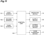
  • the control unit 100 controls, for recovery from an error, the operating device 12, the supply device 30, the bobbin holding device 14, and the yarn threading device 17 on the basis of detection results of a first sensor 101, a second sensor 102, and a third sensor 103.
  • the control unit 100 is configured as a computer device including a processor, a memory, a storage, and a communication device.
  • the control unit 100 causes the processor to execute predetermined software (program) read in the memory, for example, and controls reading and writing of data in the memory and the storage, and also communication between control devices performed by the communication device, thereby implementing functions of various types.
  • the first sensor 101 detects whether the yarn Y has been caught by the yarn threading device 17.
  • the first sensor 101 is, for example, a sensor configured to detect whether the yarn Y is present in the yarn threading device 17 when the yarn threading device 17 receives the yarn Y from the first catching-and-guiding device 8.
  • the second sensor 102 detects whether the yarn Y is being wound by the winding device 20.
  • the second sensor 102 is, for example, a sensor configured to detect whether the yarn Y is traversed in the winding device 20, a sensor configured to detect whether the storage amount of the yarn Y in the yarn storage roller 61 is smaller than an upper limit, or a sensor configured to detect whether the yarn Y traveling between the yarn storage device 6 and the winding device 20 is present.
  • the third sensor 103 detects that the yarn Y has been spun out from the air spinning device 4.
  • the third sensor 103 is, for example, a sensor configured to detect whether the yarn Y traveling between the air spinning device 4 and the yarn monitoring device 5 is present, a sensor configured to detect whether the yarn Y is present in the first catching-and-guiding device 8 when the first catching-and-guiding device 8 guides the yarn Y from the air spinning device 4 to the yarn joining device 7, or a sensor configured to detect whether the yarn Y is present on the downstream side of the yarn storage device 6 when the unstable yarn Y produced at the start of supplying of the yarn Y is suctioned to be discharged by the first catching-and-guiding device 8.
  • the supply device 30 includes a frame 31, a cam member 32, an arm 34, a clamping unit 35, a first shaft 36, a second shaft 37, a first motor 38, and a second motor 39.
  • the cam member 32 is indicated by a dashed and double-dotted line.
  • the frame 31 is attached to the frame 11 (see Fig. 1 ) of the doffing carrier 10.
  • the frame 31 supports the cam member 32, the arm 34, the clamping unit 35, the first shaft 36, the second shaft 37, the first motor 38, and the second motor 39.
  • a cam groove 33 is formed in the cam member 32.
  • the cam groove 33 has a base-end portion 33a and a distal-end portion 33b.
  • the base-end portion 33a is made wider than a portion of the cam groove 33 except the base-end portion 33a.
  • a cam follower 34a provided to the arm 34 is arranged.
  • the first shaft 36 is provided to a base-end portion of the arm 34, and the clamping unit 35 is attached to a distal-end portion of the arm 34.
  • the clamping unit 35 is configured to be capable of clamping (gripping, holding) a bobbin B.
  • the first motor 38 is coupled to the first shaft 36 with a plurality of gears (not illustrated) interposed therebetween, and swings the arm 34 and the clamping unit 35 together about the first shaft 36.
  • the second motor 39 is coupled to the second shaft 37 with a plurality of gears (not illustrated) interposed therebetween, and swings the arm 34, the clamping unit 35, and the first shaft 36 together about the second shaft 37.
  • the cam follower 34a When the supply device 30 is in a standby state, the cam follower 34a is positioned on a receiving portion 33c that is part of the cam groove 33, and the base-end portion of the arm 34 is positioned on a stopper 31a provided to the frame 31.
  • the clamping unit 35 is movable between a first position A1 and a second position A2, and is also movable between the first position A1 and a third position A3.
  • the first position A1 is a standby position of the clamping unit 35 when the supply device 30 is in the standby state.
  • the second position A2 is a position for passing a bobbin B to the pair of bobbin holders (21, 22) and receiving a bobbin B from the pair of bobbin holders 21, 22.
  • the third position A3 is a position for passing a bobbin B to a conveyor 18.
  • the conveyor 18 extends along the direction in which the spinning units 2 are aligned, and conveys a bobbin B to be stored in the bobbin stocker 15 from a bobbin supply device (not illustrated) to the doffing carrier 10, and also conveys a bobbin B, discharged from the pair of bobbin holders 21, 22, from the doffing carrier 10 to a collection box provided to the opposite side of the bobbin supply device.
  • the conveyor 18 functions as a bobbin collection section configured to collect a bobbin B discharged from the pair of bobbin holders 21, 22.
  • the bobbin holding device 14 can move between a fourth position A4 and a fifth position A5 while holding, on the bobbin stocker 15, a bobbin B to be supplied to the pair of bobbin holders 21, 22.
  • the fourth position A4 is a position on a track of the clamping unit 35 between the first position A1 and the second position A2.
  • the fifth position A5 is a position off the track of the clamping unit 35 between the first position A1 and the second position A2 (a position posterior to the fourth position A4 in the present embodiment) .
  • a track of the clamping unit 35 between the first position A1 and the third position A3 passes through an area above the fourth position A4 and the fifth position A5 in a machine height direction (height direction) that is a vertical direction.
  • the supply device 30 is controlled by the control unit 100 to supply an empty bobbin B to the pair of bobbin holders 21, 22 as described below.
  • the second motor 39 swings the arm 34, the clamping unit 35, and the first shaft 36 together about the second shaft 37.
  • the cam follower 34a moves upward to be disengaged from the receiving portion 33c of the cam groove 33.
  • the first motor 38 swings the arm 34 and the clamping unit 35 together about the first shaft 36.
  • the cam follower 34a moves in the base-end portion 33a of the cam groove 33, and the clamping unit 35 moves from the first position A1 to the second position A2 via the fourth position A4.
  • the clamping unit 35 receives a bobbin B from the bobbin holding device 14 at the fourth position A4, and passes the bobbin B to the pair of bobbin holders 21, 22 at the second position A2.
  • the error is an error that has occurred in a series of operations from when an empty bobbin B is supplied to the pair of bobbin holders 21, 22 until a predetermined amount of yarn is wound around the bobbin B.
  • a bobbin B that has been supplied to the pair of bobbin holders 21, 22 is called “first bobbin B”
  • an empty bobbin B to be supplied to the pair of bobbin holders 21, 22 is called "second bobbin B”.
  • the control unit 100 controls the respective components of the doffing carrier 10 as described below to make recovery from the first-type error.
  • the bobbin holding device 14 holding the second bobbin B moves from the fourth position A4 to the fifth position A5.
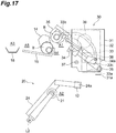
  • the clamping unit 35 moves from the first position A1 to the second position A2 via the fourth position A4, and the clamping unit 35 receives the first bobbin B from the pair of bobbin holders 21, 22 at the second position A2.
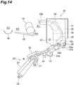
  • Operations of the respective components when the clamping unit 35 moves from the first position A1 to the second position A2 via the fourth position A4 are the same as the operations of the respective components as illustrated in Fig. 13 and Fig. 14 .
  • the first motor 38 swings the arm 34 and the clamping unit 35 together about the first shaft 36. Accordingly, the cam follower 34a moves in the base-end portion 33a of the cam groove 33, and the clamping unit 35 holding the first bobbin B moves from the second position A2 to the first position A1 via the fourth position A4.
  • the bobbin holding device 14 holding the second bobbin B moves from the fifth position A5 to the fourth position A4.
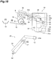
  • the second motor 39 swings the arm 34, the clamping unit 35, and the first shaft 36 about the second shaft 37. Accordingly, the cam follower 34a moves along the cam groove 33 to the distal-end portion 33b, and the clamping unit 35 holding the first bobbin B moves from the second position A2 to the third position A3 while passing through an area above the fourth position A4 and the fifthpositionA5. Subsequently, the clampingunit 35 passes the bobbin B to the conveyor 18 at the third position A3.
  • the clamping unit 35 returns to the first position A1, and supplies the second bobbin B to the pair of bobbin holders 21, 22 as illustrated in Fig. 13 and Fig. 14 .
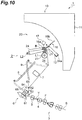
  • the yarn Y is threaded onto the second bobbin B supplied to the pair of bobbin holders 21, 22 (see Fig. 8 , Fig. 9 , and Fig. 10 ).
  • the control unit 100 controls the respective components of the doffing carrier 10 such that the first bobbin B is discharged from the pair of bobbin holders 21, 22, the second bobbin B is supplied to the pair of bobbin holders 21, 22, and the yarn Y is threaded onto the second bobbin B, thereby making recovery from the first-type error.
  • the control unit 100 controls the respective components of the doffing carrier 10 as being a case where the first-type error has been detected.
  • the first-type error is such an error that, for example, the yarn Y fails to be caught between the end portion B2 of the first bobbin B and the second bobbin holder 22 (see Fig. 2 ) or the yarn Y immediately breaks after being caught therebetween, and is an error in which unnecessary yarn Y is more likely to have been wound around the first bobbin B.
  • the control unit 100 controls the respective components of the doffing carrier 10, such that the yarn Y is threaded onto the first bobbin B as a retrial, while the state in which the first bobbin B has been supplied to the pair of bobbin holders 21, 22 is being maintained to make recovery from the second-type error.
  • the control unit 100 controls the respective components of the doffing carrier 10 as being a case where the second-type error has been detected.
  • the control unit 100 controls the respective components of the doffing carrier 10 as being the case where the second-type error has been detected.
  • the second-type error is such an error that, for example, the air spinning device 4 fails to spin the yarn Y or the yarn threading device 17 fails to receive the yarn Y from the first catching-and-guiding device 8, and is an error in which unnecessary yarn Y is less likely to have been wound around the first bobbin B.
  • the first bobbin B is discharged from the pair of bobbin holders 21, 22, the second bobbin B is supplied to the pair of bobbin holders 21, 22, and also the yarn Y is threaded onto the second bobbin B because unnecessary yarn Y is more likely to have been wound around the first bobbin B that has been supplied to the pair of bobbin holders 21, 22.
  • the bobbin B can be replaced without intervention of an operator, and this replacement of the bobbin B can prevent a package P including unnecessary yarn Y from being formed.
  • the yarn Y is threaded onto the first bobbin B while the state in which the first bobbin B has been supplied to the pair of bobbin holders 21, 22 is being maintained because unnecessary yarn Y is less likely to have been wound around the first bobbin B that has been supplied to the pair of bobbin holders 21, 22.
  • a period of time required for recovery from the error can be shortened by a period of time required for replacing the bobbin B.
  • the supply device 30 receives the first bobbin B from the pair of bobbin holders 21, 22 and passes the first bobbin B to the conveyor 18, and receives the second bobbin B from the bobbin holding device 14 and passes the second bobbin B to the pair of bobbin holders 21, 22.
  • the supply device 30 is configured such that the clamping unit 35 is movable between the first position A1 and the second position A2, and also the clamping unit 35 is movable between the first position A1 and the third position A3.
  • the bobbin holding device 14 is configured to be movable between the fourth position A4 and the fifth position A5.
  • the track of the clamping unit 35 between the first position A1 and the third position A3 passes through the area above the fourth position A4 and the fifth position A5 in the machine height direction.
  • the layouts of the bobbin holding device 14, the conveyor 18, and the supply device 30 can be further simplified, and also the movement paths of the bobbin holding device 14 and the supply device 30 can be further simplified.
  • the bobbin collection section configured to collect the first bobbin B discharged from the pair of bobbin holders 21, 22 is configured as the conveyor 18 configured to convey the first bobbin B.
  • the first bobbin B can be automatically conveyed to a predetermined location.
  • the control unit 100 controls the operating device 12, the supply device 30, and the yarn threading device 17 as being the case where the first-type error has been detected.
  • unnecessary yarn Y is more likely to have been wound around the first bobbin B that has been supplied to the pair of bobbin holders 21, 22.
  • the bobbin B can be replaced without intervention of the operator, and this replacement of the bobbin B can prevent a package P including unnecessary yarn Y from being formed.
  • the control unit 100 controls the operating device 12, the supply device 30, and the yarn threading device 17 as being the case where the second-type error has been detected.
  • unnecessary yarn Y is less likely to have been wound around the first bobbin B that has been supplied to the pair of bobbin holders 21, 22.
  • a period of time required for recovery from the error can be shortened by a period of time required for replacing the bobbin B.
  • winding of the yarn Y around the first bobbin B is started without replacing the first bobbin B supplied to the pair of bobbin holders 21, 22, and thus, decrease in the operating rate of the spinning unit 2 can be reduced.
  • the control unit 100 controls the operating device 12, the supply device 30, and the yarn threading device 17 as being the case where the second-type error has been detected.
  • unnecessary yarn Y is less likely to have been wound around the first bobbin B that has been supplied to the pair of bobbin holders 21, 22.
  • the winding device 20 is disposed at a position for winding the yarn Y traveling upward from the lower side. Thus, even if the position of the winding device 20 is high, recovery from the error is automatically made, which can prevent decrease in operating rate of the spinning unit 2 due to work of the operator at a high place.
  • a yarn threading method that is performed in the spinning machine 1 includes: a step of discharging the first bobbin B from the pair of bobbin holders 21, 22, supplying the second bobbin B to the pair of bobbin holders 21, 22, and threading the yarn Y onto the second bobbin B when the first-type error that occurs after the catching operation of the yarn threading device 17 to catch the yarn Y has been detected in a state in which the first bobbin B has been supplied to the pair of bobbin holders 21, 22; and a step of threading the yarn Y onto the first bobbin B while maintaining a state in which the first bobbin B has been supplied to the pair of bobbin holders 21, 22 when the second-type error that occurs before the catching operation of the yarn threading device 17 to catch the yarn Y or during the catching operation has been detected in the state in which the first bobbin B has been supplied to the pair of bobbin holders 21, 22.
  • the bobbin collection section configured to collect a first bobbin B discharged from the pair of bobbin holders 21, 22 may be configured as a stocker configured to store the first bobbin B.
  • the first bobbin B can be collected without using the conveyor 18 or the like, and the first bobbin B stored in the stocker can be automatically discharged to a collection box, for example, provided in a predetermined location or can be collected by the operator.
  • this stocker can be provided to the doffing carrier 10.
  • a device configured to receive a first bobbin B from the pair of bobbin holders 21, 22 and pass the first bobbin B to a bobbin collection section such as the conveyor 18, may be provided separately from the supply device 30.
  • Respective devices configured to make recovery from an error that has occurred in a series of operations from when an empty bobbin B is supplied to the pair of bobbin holders 21, 22 until a predetermined amount of yarn is wound around the bobbin B may be provided separately from the doffing carrier 10.
  • the doffing carrier 10 does not have to include the bobbin stocker 15, and the supply device 30 may receive an empty bobbin B conveyed by the conveyor 18 and supply it directly to the winding device 20.
  • the doffing carrier 10 only needs to have a function of doffing a package P, and does not have to have a function of supplying an empty bobbin B.
  • the drafting device 3 includes the roller pairs.
  • the roller pair (front roller pair) disposed at a position closest to the air spinning device 4 in the traveling direction of the fiber bundle F may be configured as part of another device.
  • the spinning unit 2 may include a supply device configured to supply the fiber bundle F drafted by the drafting device 3 to the air spinning device 4, and the front roller pair may be included in part of this supply device.
  • the front roller pair may be included in the drafting device 3 configured to draft the sliver S or the supply device configured to supply the fiber bundle F to the air spinning device 4, or may be provided independently without being included in another device.
  • a combing roller may be provided instead of the drafting device 3, and the air spinning device 4 may twist the fiber bundle F supplied from the combing roller to form the yarn Y.
  • the air spinning device 4 may include a pair of air-jet nozzles configured to twist the fiber bundle F in directions opposite to each other.
  • the winding device 20 is not limited to a type in which the drum 23 is rotationally driven, whereby a bobbin B being in contact with the drum 23 is rotated in a driven manner.
  • the winding device 20 may be of a type in which a bobbin B is rotationally driven, whereby a drum 23 being in contact with the bobbin B is rotated in a driven manner.
  • the drum 23 only needs to be a drum configured to rotate while being in contact with a bobbin B.
  • the traveling direction of the yarn Y is turned at the yarn storage device 6.
  • the traveling direction of the yarn Y does not have to be turned at the yarn storage device 6.
  • the respective devices are disposed such that the yarn Y supplied from the lower side is wound on the upper side in the machine height direction.
  • the respective devices may be disposed such that the yarn Y supplied from the upper side is wound on the lower side in the machine height direction.
  • the doffing carrier 10 may be provided so as to travel on a traveling path in a lower portion of the spinning machine 1, and also a discharged first bobbin B may be discharged to a discharge section in a lower portion of the spinning machine 1.
  • a delivery roller and a nip roller may be disposed between the air spinning device 4 and the yarn storage device 6.
  • a slack tube using suction airflow and/or a mechanical compensator may be provided instead of the yarn storage device 6.
  • the yarn monitoring device 5 may be disposed between the yarn storage device 6 and the winding device 20.
  • the yarn joining device 7, the first catching-and-guiding device 8, and the second catching-and-guiding device 9 may be provided to a yarn joining carrier that is movable along a direction in which the spinning units 2 are aligned.
  • Each spinning unit 2 or the doffing carrier 10 may be provided with a yarn draw-out device configured to pull out the yarn Y from a package P when yarn joining is performed, for example.
  • the yarn winding machine is not limited to the spinning machine 1, and may be an open-end spinning machine, for example.
  • the open-end spinning machine is a spinning machine including the spinning units 2 in each of which an open-end spinning device (rotor-type spinning device) is provided instead of the drafting device 3 and the air spinning device 4.
  • the open-end spinning device is a device configured to separate fibers of the sliver S using a combing roller or airflow, convey the separated fibers using airflow into a rotor that is rotating at high speed, and cause the fibers to be gathered into a bundle on an inner wall of the rotor. The gathered fibers are drawn out from the open-end spinning device, whereby the yarn Y is formed.
  • the yarn Y from the air spinning device 4 and the yarn Y from a package P may be connected (pieced) by inserting the yarn Y from the package P into the air spinning device 4 and starting the drafting operation of the drafting device 3 and the spinning operation of the air spinning device 4.
  • the materials and shapes of the respective components described above are not limited to those described above, and various types of materials and shapes may be used. At least some configurations in the embodiment described above may be optionally used in combination with at least some other configurations in the embodiment.
  • a yarn winding machine and a yarn threading method with which, even if an error has occurred in a series of operations from when a bobbin is supplied to a pair of bobbin holders until a predetermined amount of yarn is wound around the bobbin, load on an operator related to recovery from the error can be reduced and decrease in operating rate caused by the recovery from the error can be reduced.

Landscapes

  • Engineering & Computer Science (AREA)
  • Textile Engineering (AREA)
  • Spinning Or Twisting Of Yarns (AREA)
  • Replacing, Conveying, And Pick-Finding For Filamentary Materials (AREA)

Abstract

A yarn winding machine includes a winding device, an operating device, a supply device, a yarn threading device, and a control unit. The control unit is configured to perform a first control when a first-type error has been detected, the first control performed to control the operating device, the supply device, and the yarn threading device such that a first bobbin is discharged from a pair of bobbin holders, a second bobbin is supplied to the bobbin holders, and the yarn is threaded onto the second bobbin. The control unit is configured to perform a second control when a second-type error has been detected, the second control performed to control the operating device, the supply device, and the yarn threading device such that the yarn is threaded onto the first bobbin while the state in which the first bobbin has been supplied to the bobbin holders is being maintained.

Description

    TECHNICAL FIELD
  • The present disclosure relates to a yarn winding machine and a yarn threading method.
  • BACKGROUND
  • In a yarn winding machine such as a spinning machine, for example, after a fully-wound package has been discharged from a winding device by a doffing carrier, a supply device provided to the doffing carrier may supply a bobbin to a pair of bobbin holders provided to the winding device, and also, a yarn threading device provided to the doffing carrier may thread yarn onto the bobbin (see Japanese Unexamined Patent Publication No. 2006-225092 , for example).
  • SUMMARY
  • In the above-described yarn winding machine, if some error has occurred in a series of operations from when a bobbin is supplied to the pair of bobbin holders until a predetermined amount of yarn is wound around the bobbin, this series of operations may be performed again from a point when a new empty bobbin is supplied to the pair of bobbin holders. This is because there is a possibility that unnecessary yarn might have been wound around the current bobbin that has been supplied to the pair of bobbin holders before the occurrence of the error. However, if the series of operations is performed again for all cases, an operator has to collect the current bobbin every time an error occurs, which increases load on the operator. Furthermore, every time an error occurs, a certain period of time is required for replacing the bobbin, and the operating rate decreases accordingly.
  • It is an object of the present disclosure to provide a yarn winding machine and a yarn threading method with which even if an error has occurred in a series of operations from when a bobbin is supplied to a pair of bobbin holders until a predetermined amount of yarn is wound around the bobbin, load on an operator related to recovery from the error can be reduced and decrease in operating rate caused by the recovery from the error can be reduced.
  • A yarn winding machine according to one aspect of the present disclosure includes: a winding device including a pair of bobbin holders configured to hold a bobbin and a cradle configured to support the pair of bobbin holders; an operating device configured to operate the cradle to open and close the pair of bobbin holders; a supply device configured to supply the bobbin to the pair of bobbin holders; a yarn threading device configured to catch yarn and thread the yarn onto the bobbin; and a control unit configured to control the operating device, the supply device, and the yarn threading device. The control unit is configured to perform a first control when a first-type error that occurs after a catching operation of the yarn threading device to catch the yarn has been detected in a state in which a first bobbin as the bobbin has been supplied to the pair of bobbin holders, the first control performed to control the operating device, the supply device, and the yarn threading device such that the first bobbin is discharged from the pair of bobbin holders, a second bobbin as the bobbin is supplied to the pair of bobbin holders, and the yarn is threaded onto the second bobbin. The control unit is configured to perform a second control when a second-type error that occurs before the catching operation or during the catching operation has been detected in a state in which the first bobbin has been supplied to the pair of bobbin holders, the second control performed to control the operating device, the supply device, and the yarn threading device such that the yarn is threaded onto the first bobbin while the state in which the first bobbin has been supplied to the pair of bobbin holders is being maintained.
  • In this yarn winding machine, depending on the type of an error that has occurred in a series of operations from when a bobbin is supplied to the pair of bobbin holders until a predetermined amount of yarn is wound around the bobbin, details of operation for recovery from the error are changed. Specifically, when the first-type error that occurs after a catching operation of the yarn threading device to catch yarn has been detected, the first bobbin is discharged from the pair of bobbin holders, the second bobbin is supplied to the pair of bobbin holders, and the yarn is threaded onto the second bobbin because unnecessary yarn is more likely to have been wound around the first bobbin that has been supplied to the pair of bobbin holders. Thus, the bobbin can be replaced without intervention of an operator, and this replacement of the bobbin can prevent a package, including unnecessary yarn, from being formed. Furthermore, when the second-type error that occurs before the catching operation of the yarn threading device to catch yarn or during the catching operation has been detected, yarn is threaded onto the first bobbin while the state in which the first bobbin has been supplied to the pair of bobbin holders is being maintained, because unnecessary yarn is less likely to have been wound around the first bobbin that has been supplied to the pair of bobbin holders. Thus, a period of time required for recovery from the error can be shortened by a period of time required for replacing the bobbin. As described above, with this yarn winding machine, even if an error has occurred in a series of operations from when a bobbin is supplied to the pair of bobbin holders until a predetermined amount of yarn is wound around the bobbin, load on the operator related to recovery from the error can be reduced and decrease in operating rate caused by the recovery from the error can be reduced.
  • The yarn winding machine according to one aspect of the present disclosure may further include: a bobbin collection section configured to collect the first bobbin discharged from the pair of bobbin holders when the first-type error has been detected; and a bobbin holding device configured to hold the second bobbin to be supplied to the pair of bobbin holders when the first-type error has been detected. The supply device may be configured to receive the first bobbin from the pair of bobbin holders and pass the first bobbin to the bobbin collection section, and to receive the second bobbin from the bobbin holding device and pass the second bobbin to the pair of bobbin holders, when the first-type error has been detected. This eliminates the need to provide a device configured to receive the first bobbin from the pair of bobbin holders and pass the first bobbin to the bobbin collection section in addition to the supply device, and thus, the configuration can be simplified.
  • In the yarn winding machine according to one aspect of the present disclosure, the supply device may include a clamping unit configured to clamp the bobbin, and may be configured such that the clamping unit is movable between a first position and a second position, and the clamping unit is movable between the first position and a third position. The first position is a standby position of the clamping unit, the second position is a position for passing the bobbin to the pair of bobbin holders and receiving the bobbin from the pair of bobbin holders, and the third position is a position for passing the bobbin to the bobbin collection section. The bobbin holding device may be configured to be movable between a fourth position and a fifth position. The fourth position is a position on a track of the clamping unit between the first position and the second position, and the fifth position is a position off the track of the clamping unit between the first position and the second position. With this configuration, the layouts of the bobbin holding device, the bobbin collection section, and the supply device can be simplified, and also the movement paths of the bobbin holding device and the supply device can be simplified.
  • In the yarn winding machine according to one aspect of the present disclosure, the track of the clamping unit between the first position and the third position may pass through an area above the fourth position and the fifth position in a height direction. With this configuration, the layouts of the bobbin holding device, the bobbin collection section, and the supply device can be further simplified, and also the movement paths of the bobbin holding device and the supply device can be further simplified.
  • In the yarn winding machine according to one aspect of the present disclosure, the bobbin collection section may comprise a conveyor configured to convey the first bobbin. With this configuration, the first bobbin can be automatically conveyed to a predetermined location.
  • In the yarn winding machine according to one aspect of the present disclosure, the bobbin collection section may comprise a stocker configured to store the first bobbin. With this configuration, the first bobbin can be collected without using the conveyor or the like, and the first bobbin stored in the stocker can be automatically discharged to a collection box, for example, provided in a predetermined location or can be collected by the operator.
  • The yarn winding machine according to one aspect of the present disclosure may further include: a first sensor configured to detect whether the yarn has been caught by the yarn threading device; and a second sensor configured to detect whether the yarn is being wound by the winding device. The control unit may be configured to perform the first control when the first sensor has detected that the yarn has been caught and then the second sensor has detected that the yarn is not being wound, as being a case where the first-type error has been detected. When the first sensor has detected that the yarn has been caught and then the second sensor has detected that the yarn is not being wound, unnecessary yarn is more likely to have been wound around the first bobbin that has been supplied to the pair of bobbin holders. Thus, in this case, by controlling the operating device, the supply device, and the yarn threading device as being the case where the first-type error has been detected, the bobbin can be replaced without intervention of the operator, and this replacement of the bobbin can prevent a package including unnecessary yarn from being formed.
  • The yarn winding machine according to one aspect of the present disclosure may further include: an air spinning device configured to twist a fiber bundle using swirling airflow to form the yarn; and a third sensor configured to detect whether the yarn has been spun out from the air spinning device. The control unit may be configured to perform the second control when the third sensor has detected that the yarn has not been spun out, as being a case where the second-type error has been detected. When the third sensor has detected that the yarn has not been spun out, unnecessary yarn is less likely to have been wound around the first bobbin that has been supplied to the pair of bobbin holders. Thus, in this case, by controlling the operating device, the supply device, and the yarn threading device as being the case where the second-type error has been detected, a period of time required for recovery from the error can be shortened by a period of time required for replacing the bobbin.
  • In the yarn winding machine according to one aspect of the present disclosure, the control unit may be configured to perform the second control when the third sensor has detected that the yarn has been spun out and then the first sensor has detected that the yarn has not been caught, as being the case where the second-type error has been detected. When the third sensor has detected that the yarn has been spun out and then the first sensor has detected that the yarn has not been caught, unnecessary yarn is less likely to have been wound around the first bobbin that has been supplied to the pair of bobbin holders. Thus, in this case, by controlling the operating device, the supply device, and the yarn threading device as being the case where the second-type error has been detected, a period of time required for recovery from the error can be shortened by a period of time required for replacing the bobbin.
  • In the yarn winding machine according to one aspect of the present disclosure, the winding device may be disposed at a position for winding the yarn traveling upward from a lower side. With this configuration, even if the position of the winding device is high, recovery from the error is automatically made, which can prevent decrease in the operating rate of the yarn winding machine due to work of the operator at a high place.
  • A yarn threading method according to one aspect of the present disclosure is a yarn threading method that is performed in a yarn winding machine including: a winding device including a pair of bobbin holders configured to hold a bobbin and a cradle configured to support the pair of bobbin holders; an operating device configured to operate the cradle to open and close the pair of bobbin holders; a supply device configured to supply the bobbin to the pair of bobbin holders; and a yarn threading device configured to catch yarn and thread the yarn onto the bobbin. The yarn threading method includes: a step of, when a first-type error that occurs after catching operation of the yarn threading device to catch the yarn has been detected in a state in which a first bobbin as the bobbin has been supplied to the pair of bobbin holders, discharging the first bobbin from the pair of bobbin holders, supplying a second bobbin as the bobbin to the pair of bobbin holders, and threading the yarn onto the second bobbin; and a step of, when a second-type error that occurs before the catching operation or during the catching operation has been detected in a state in which the first bobbin has been supplied to the pair of bobbin holders, threading the yarn onto the first bobbin while maintaining the state in which the first bobbin has been supplied to the pair of bobbin holders.
  • With this yarn threading method, similarly to the above-described yarn winding machine, even if an error has occurred in a series of operations from when a bobbin is supplied to the pair of bobbin holders until a predetermined amount of yarn is wound around the bobbin, load on the operator related to recovery from the error can be reduced and decrease in operating rate caused by the recovery from the error can be reduced.
  • BRIEF DESCRIPTION OF THE DRAWINGS
    • Fig. 1 is a side view of a spinning machine as one embodiment of a yarn winding machine of the present disclosure.
    • Fig. 2 is a front view of a winding device illustrated in Fig. 1.
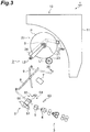
    • Fig. 3 is a side view of the spinning machine for describing operation of the spinning machine illustrated in Fig. 1.
    • Fig. 4 is a side view of the spinning machine for describing the operation of the spinning machine illustrated in Fig. 1.
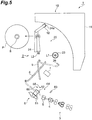
    • Fig. 5 is a side view of the spinning machine for describing the operation of the spinning machine illustrated in Fig. 1.
    • Fig. 6 is a side view of the spinning machine for describing the operation of the spinning machine illustrated in Fig. 1.
    • Fig. 7 is a side view of the spinning machine for describing the operation of the spinning machine illustrated in Fig. 1.
    • Fig. 8 is a side view of the spinning machine for describing the operation of the spinning machine illustrated in Fig. 1.
    • Fig. 9 is a side view of the spinning machine for describing the operation of the spinning machine illustrated in Fig. 1.
    • Fig. 10 is a side view of the spinning machine for describing the operation of the spinning machine illustrated in Fig. 1.
    • Fig. 11 is a block diagram of a configuration related to a control unit illustrated in Fig. 1.
    • Fig. 12 is a side view of part of the spinning machine illustrated in Fig. 1.
    • Fig. 13 is a side view of a supply device for describing operation of a doffing carrier illustrated in Fig. 1.
    • Fig. 14 is a side view of the supply device for describing the operation of the doffing carrier illustrated in Fig. 1.
    • Fig. 15 is a side view of the supply device for describing the operation of the doffing carrier illustrated in Fig. 1.
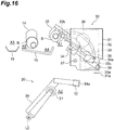
    • Fig. 16 is a side view of the supply device for describing the operation of the doffing carrier illustrated in Fig. 1.
    • Fig. 17 is a side view of the supply device for describing the operation of the doffing carrier illustrated in Fig. 1.
    • Fig. 18 is a side view of the supply device for describing the operation of the doffing carrier illustrated in Fig. 1.
    • Fig. 19 is a side view of the supply device for describing the operation of the doffing carrier illustrated in Fig. 1.
    DETAILED DESCRIPTION
  • An embodiment of the present disclosure will now be described in detail with reference to the drawings. In the drawings, like or equivalent elements are designated by like numerals, and duplicate description is omitted.
  • [Configuration of Spinning Machine]
  • As illustrated in Fig. 1, a spinning machine (yarn winding machine) 1 includes a plurality of spinning units (yarn winding units) 2, a doffing carrier 10, and a control unit 100. The spinning units 2 are aligned in a row. Each spinning unit 2 drafts a sliver (fiber bundle) S to form a fiber bundle F, twists the fiber bundle F using swirling airflow to form yarn Y, and winds the yarn Y around a bobbin B to form a package P. The doffing carrier 10 is movable along a direction in which the spinning units 2 are aligned. When a fully-wound package P has been formed in a certain spinning unit 2, the doffing carrier 10 discharges the fully-wound package P from the spinning unit 2, and supplies an empty bobbin B to the spinning unit 2. The control unit 100 controls operation of the spinning machine 1. The control unit 100 is configured with a machine control device and a plurality of unit controllers, for example. The machine control device is a host controller of the unit controllers. Each unit controller is provided for every predetermined number of (one or more) spinning units 2, and controls operation of each spinning unit 2.
  • Hereinafter, the upstream side of the sliver S, the fiber bundle F, and the yarn Y in their traveling direction is called "upstream side", and the downstream side in the traveling direction is called "downstream side". One side in a horizontal direction orthogonal to the direction in which the spinning units 2 are aligned (e.g., working passage side) is called "front side", and the other side in the horizontal direction is called "rear side". The upper side in the vertical direction is called "upper side", and the lower side in the vertical direction is called "lower side".
  • Each spinning unit 2 includes, in the order from the upstream side toward the downstream side, a drafting device 3, an air spinning device 4, a yarn monitoring device 5, a yarn storage device 6, a yarn joining device 7, and a winding device 20. The spinning unit 2 further includes a first catching-and-guiding device 8 and a second catching-and-guiding device 9. As one example, the traveling direction of the sliver S, the fiber bundle F, and the yarn Y from the drafting device 3 to the yarn storage device 6 is a direction extending from the front side toward the rear side, and is inclined upward with respect to the horizontal direction. The traveling direction of the yarn Y from the yarn storage device 6 to the winding device 20 is a direction extending from the lower side toward the upper side, and is inclined forward with respect to the vertical direction. In each spinning unit 2, the traveling direction of the yarn Y is turned at the yarn storage device 6.
  • The drafting device 3 drafts the sliver S to form the fiber bundle F, and feeds the fiber bundle F to the air spinning device 4. The drafting device 3 includes a plurality of roller pairs aligned from the upstream side toward the downstream side and apron belts wound around the respective rollers of a predetermined roller pair. The air spinning device 4 twists the fiber bundle F from the drafting device 3 using swirling airflow to form the yarn Y.
  • The yarn monitoring device 5 monitors information on traveling the yarn Y to detect the presence or absence of a yarn defect on the basis of the monitored information. When having detected a yarn defect, the yarn monitoring device 5 transmits a yarn-defect detection signal to the control unit 100. When having received the yarn-defect detection signal, in order to cut the yarn Y, the control unit 100 causes the drafting device 3 and the air spinning device 4 to stop operating such that supply of the yarn Y is stopped. When having received the yarn-defect detection signal, in order to cut the yarn Y, the control unit 100 may cause a cutter provided to the yarn monitoring device 5, for example, to operate.
  • The yarn storage device 6 includes a yarn storage roller 61 and a yarn hooking member 62. The yarn storage roller 61 is rotated by an electric motor (not illustrated). The yarn hooking member 62 is attached to a downstream end portion of the yarn storage roller 61, and is rotatable relative to the yarn storage roller 61. Herein, magnetic force that interferes with rotation relative to the yarn storage roller 61 acts on the yarn hooking member 62. Thus, when a tension equal to or higher than a predetermined value is not applied to the yarn Y, the yarn hooking member 62 rotates together with the yarn storage roller 61, whereby the yarn Y is wound (stored) around the yarn storage roller 61. When a tension equal to or higher than the predetermined value is applied to the yarn Y, the yarn hooking member 62 rotates relative to the yarn storage roller 61, whereby the yarn Y is unwound from the yarn storage roller 61. The yarn storage device 6 stores the yarn Y in this manner, thereby absorbing variation in tension applied to the yarn Y on the downstream side of the yarn storage device 6, and stably drawing out the yarn Y from the air spinning device 4.
  • On the upstream side of the yarn storage device 6, a first guide 63 is disposed. The first guide 63 guides the yarn Y traveling from the upstream side to the yarn storage device 6. The first guide 63 is movable, and draws the yarn Y from the air spinning device 4 toward the yarn storage device 6 when yarn joining is performed, for example. On the downstream side of the yarn storage device 6, a second guide 64, a third guide 65, and a fourth guide 66 are disposed. The second guide 64 and the third guide 65 guide the yarn Y traveling from the yarn storage device 6 to the downstream side. The second guide 64 is movable, and can guide the yarn Y to the third guide 65. The fourth guide 66 is movable, and hooks the yarn Y onto the yarn hooking member 62 and unhooks the yarn Y from the yarn hooking member 62.
  • When the yarn Y has been cut or the yarn Y has broken for some reason, the yarn joining device 7 joins the yarn Y from the air spinning device 4 and the yarn Y from a package P. The yarn joining device 7 is a splicer device configured to twist yarn ends together using swirling airflow. Herein, the yarn joining device 7 may be a mechanical knotter, for example. Each of the first catching-and-guiding device 8 and the second catching-and-guiding device 9 is swingable about its base-end portion. When yarn joining is to be performed, the first catching-and-guiding device 8 swings downward to catch the yarn Y from the air spinning device 4 using suction airflow, and then swings upward to guide the yarn Y from the air spinning device 4 to the yarn joining device 7. When the yarn joining is to be performed, the second catching-and-guiding device 9 swings upward to catch the yarn Y from the package P using suction airflow, and then swings downward to guide the yarn Y from the package P to the yarn joining device 7.
  • The winding device 20 winds the yarn Y, drawn out by the yarn storage device 6, around a bobbin B to form a package P. As illustrated in Fig. 1 and Fig. 2, the winding device 20 includes a drum 23, a first bobbin holder 21 and a second bobbin holder 22 as a pair of bobbin holders, and a cradle 24. On the upstream side of the winding device 20, a fifth guide 26 is disposed. The fifth guide 26 guides the yarn Y traveling from the upstream side to the drum 23. Although an empty bobbin B around which the yarn Y is not wound is illustrated in Fig. 2, the respective components of the winding device 20 function in the same manner also for a package P (see Fig. 1) with the yarn Y wound around the bobbin B.
  • The drum 23 rotates the bobbin B while making contact with the bobbin B. When the yarn Y is being wound around the bobbin B, the drum 23 rotates the package P while being in contact with the package P. The drum 23 is rotatably supported by the frame 25, and is rotated about a rotation axis L1 by a drum driving section (not illustrated) provided to each spinning unit 2. In other words, each spinning unit 2 includes the drum driving section configured to drive the drum 23. On a surface of the drum 23, a traverse groove (not illustrated) is formed. By this traverse groove, the yarn Y is traversed when the yarn Y is wound around the bobbin B. Herein, instead of forming the traverse groove on the surface of the drum 23, the yarn Y may be traversed by an additionally provided traversing device when the yarn Y is wound around the bobbin B.
  • The first bobbin holder 21 holds an end portion B1 of the bobbin B, and the second bobbin holder 22 holds an end portion B2 of the bobbin B. The pair of bobbin holders 21, 22 holds both end portions of the bobbin B in this manner, thereby holding the bobbin B. The cradle 24 rotatably supports the pair of bobbin holders 21, 22 in a manner that the pair of bobbin holders 21, 22 can be opened and closed and the pair of bobbin holders 21, 22 can be moved with respect to the drum 23. The cradle 24 is swingable about a swinging axis L2. The cradle 24 swings about the swinging axis L2, thereby absorbing an increase in diameter of the package P associated with winding of the yarn Y around the bobbin B.
  • The cradle 24 includes a cradle arm 24a. The cradle arm 24a is attached to a portion of the cradle 24 that supports the second bobbin holder 22. By operating the cradle arm 24a, the pair of bobbin holders 21, 22 can be opened and closed. Specifically, by operating the cradle arm 24a such that the second bobbin holder 22 is separated from the first bobbin holder 21 to swing outward the portion of the cradle 24 that supports the second bobbin holder 22, the pair of bobbin holders 21, 22 that is urged so as to hold the bobbin B can be opened. In other words, the distance between the pair of bobbin holders 21, 22 when the pair of bobbin holders 21, 22 is opened is larger than the distance between the pair of bobbin holders 21, 22 when the pair of bobbin holders 21, 22 is closed.
  • By operating the cradle arm 24a, the pair of bobbin holders 21, 22 can be moved with respect to the drum 23. Specifically, by operating the cradle arm 24a such that the pair of bobbin holders 21, 22 is separated from the drum 23 to swing the cradle 24 about the swinging axis L2, the bobbin B or the package P can be moved apart from the drum 23.
  • As illustrated in Fig. 1, the doffing carrier 10 includes a frame 11, an operating device 12, a discharge device (not illustrated), a supply device 30, a bobbin holding device 14, a bobbin stocker 15, a pressing device 16, and a yarn threading device 17. The frame 11 supports the operating device 12, the discharge device, the supply device 30, the bobbin holding device 14, the bobbin stocker 15, the pressing device 16, and the yarn threading device 17.
  • [Configuration and Operation of Doffing Carrier]
  • The following describes a configuration and operation of each component of the doffing carrier 10 with reference to Fig. 3 to Fig. 10. Although the control unit 100 is not illustrated in Fig. 3 to Fig. 10, operation of each component of the doffing carrier 10 is controlled by the control unit 100.
  • As illustrated in Fig. 3, when a fully-wound package P has been formed by the winding device 20, operations of the drafting device 3 and the air spinning device 4 are stopped to stop supply of the yarn Y, and the drum driving section is stopped to stop rotation of the drum 23. At this time, the first guide 63 and the second guide 64 move to positions apart from the yarn storage roller 61 and the yarn hooking member 62. Subsequently, the operating device 12 holds the cradle arm 24a and operates the cradle arm 24a. By this operation, the pair of bobbin holders 21, 22 is moved to a discharge position as illustrated in Fig. 4. The discharge position is a position where the fully-wound package P is located away from the drum 23. In this manner, the operating device 12 operates the cradle 24 such that the pair of bobbin holders 21, 22 moves with respect to the drum 23.
  • Subsequently, as illustrated in Fig. 5, the operating device 12 operates the cradle arm 24a to open the pair of bobbin holders 21, 22, and the discharge device discharges the fully-wound package P from the pair of bobbin holders 21, 22 positioned at the discharge position. In this manner, the operating device 12 operates the cradle 24 such that the pair of bobbin holders 21, 22 is opened and closed. Subsequently, as illustrated in Fig. 6, the operating device 12 operates the cradle arm 24a to move the pair of bobbin holders 21, 22 to a supply position. The supply position is a position that is closer to the drum 23 than the discharge position (see Fig. 4 and Fig. 5) is.
  • Subsequently, as illustrated in Fig. 7, the bobbin holding device 14 passes an empty bobbin B stored in the bobbin stocker 15 to the supply device 30, and the supply device 30 supplies, from the upper side, the empty bobbin B to the pair of bobbin holders 21, 22 that is positioned at the supply position and is opened (see Fig. 2). Subsequently, the operating device 12 operates the cradle arm 24a to close the pair of bobbin holders 21, 22, so that the first bobbin holder 21 holds the end portion B1 of the bobbin B and the second bobbin holder 22 holds the end portion B2 of the bobbin B. Subsequently, as illustrated in Fig. 8, the operating device 12 operates the cradle arm 24a to move the pair of bobbin holders 21, 22 to a yarn threading position. The yarn threading position is a position that is closer to the drum 23 than the supply position (see Fig. 6 and Fig. 7) is, and is a position where the bobbin B held by the pair of bobbin holders 21, 22 comes into contact with the drum 23.
  • The pair of bobbin holders 21, 22 is moved to the yarn threading position and, operations of the drafting device 3 and the air spinning device 4 are started to start (restart) supply of the yarn Y. At this time, the first catching-and-guiding device 8 that has swung downward catches the yarn Y from the air spinning device 4 using suction airflow, and then the first catching-and-guiding device 8 swings upward to guide the yarn Y from the air spinning device 4 to the yarn joining device 7. Subsequently, the first guide 63 moves closer to the yarn storage roller 61, whereby the yarn Y from the air spinning device 4 is drawn toward the yarn storage device 6. Furthermore, the second guide 64 moves closer to the yarn hooking member 62, whereby the yarn Y from the air spinning device 4 is hooked on the yarn hooking member 62. Thus, the yarn Y from the air spinning device 4 is wound around the yarn storage roller 61.
  • Subsequently, as illustrated in Fig. 9, when the pair of bobbin holders 21, 22 is positioned at the yarn threading position, the pressing device 16 presses the bobbin B held by the pair of bobbin holders 21, 22 against the drum 23. The pressing device 16 has a contact portion 16a configured to come into contact with the bobbin B and a moving mechanism 16b configured to move the contact portion 16a, and the contact portion 16a is attached to the moving mechanism 16b in a replaceable manner. The contact portion 16a is replaced depending on the type of a bobbin B. While the pressing device 16 is pressing the bobbin B against the drum 23, the fourth guide 66 moves so as to remove the yarn Y from the yarn hooking member 62, whereby the yarn Y is removed from the yarn hooking member 62. Thus, the yarn Y is unwound from the yarn storage roller 61, and the unstable yarn Y formed at the start of supplying of the yarn Y, is suctioned to be discarded by the first catching-and-guiding device 8. Subsequently, the yarn threading device 17 moves near the yarn joining device 7 to receive the yarn Y from the first catching-and-guiding device 8. Specifically, the yarn threading device 17 catches the yarn Y drawn out by the yarn storage device 6 using suction airflow.
  • Subsequently, as illustrated in Fig. 10, while the pressing device 16 is pressing the bobbin B against the drum 23, the operating device 12 operates the cradle arm 24a, whereby a space is formed between the end portion B2 of the bobbin B and the second bobbin holder 22 (see Fig. 2). Meanwhile, the fourth guide 66 moves to the standby position, whereby the yarn Y from the air spinning device 4 is hooked on the yarn hooking member 62. Thus, the yarn Y from the air spinning device 4 is wound around the yarn storage roller 61. Subsequently, the yarn threading device 17 guides the yarn Y to the space formed between the end portion B2 of the bobbin B and the second bobbin holder 22. Subsequently, with the yarn Y being positioned in the space, the operating device 12 operates the cradle arm 24a to close the pair of bobbin holders 21, 22, whereby the yarn Y is threaded onto the bobbin B. When the pair of bobbin holders 21, 22 has been closed, the yarn threading device 17 cuts the yarn Y between the yarn threading device 17 and the bobbin B. In this manner, the yarn threading device 17 threads the yarn Y drawn out by the yarn storage device 6 onto the bobbin B from the lower side with the pair of bobbin holders 21, 22 being opened and closed under a state in which the pair of bobbin holders 21, 22 is positioned at the yarn threading position. When the yarn threading device 17 threads the yarn Y onto the bobbin B, the drum driving section is stopping the rotation of the drum 23.
  • When the yarn Y has been threaded onto the bobbin B, the operating device 12, the pressing device 16, and the yarn threading device 17 return to the standby positions in the doffing carrier 10, and the drum driving section is operated to start rotation of the drum 23, whereby formation of a package P (winding of the yarn Y around the bobbin B) by the winding device 20 is started. More specifically, at the start of forming a package P, the yarn Y is restricted by a restriction guide (not illustrated) provided to the doffing carrier 10 so as not to be traversed along the traverse groove, and thus, a bunch is wound and formed on an inner side of the end portion B2 of the bobbin B in the axial direction. After the bunch has been wound and formed, the restriction of the yarn Y by the restriction guide is released, and formation of the package P is continued. In the spinning machine 1, each spinning unit 2 includes a draft driving section (not illustrated) configured to drive the corresponding drafting device 3, and the drafting device 3 operates at a drafting speed depending on a state of the spinning unit 2. The drafting speed during a winding period for the winding device 20 to wind the yarn Y around the bobbin B (a period of time from when the winding device 20 starts winding the yarn Y around an empty bobbin B until a fully-wound package P is formed) is higher than the drafting speed during a preparation period (a period of time between a winding period and the subsequent winding period) other than the winding period. Herein, the drafting speed is, for example, an average drafting speed depending on the spinning speed of the air spinning device 4.
  • [Recovery from Error that has Occurred After Bobbin is Supplied]
  • The following describes recovery from an error that has occurred in a series of operations from when an empty bobbin B is supplied to the pair of bobbin holders 21, 22 until a predetermined amount of yarn is wound around the bobbin B (hereinafter, also simply called "error"). As illustrated in Fig. 11, the control unit 100 controls, for recovery from an error, the operating device 12, the supply device 30, the bobbin holding device 14, and the yarn threading device 17 on the basis of detection results of a first sensor 101, a second sensor 102, and a third sensor 103. The control unit 100 is configured as a computer device including a processor, a memory, a storage, and a communication device. The control unit 100 causes the processor to execute predetermined software (program) read in the memory, for example, and controls reading and writing of data in the memory and the storage, and also communication between control devices performed by the communication device, thereby implementing functions of various types.
  • The first sensor 101 detects whether the yarn Y has been caught by the yarn threading device 17. The first sensor 101 is, for example, a sensor configured to detect whether the yarn Y is present in the yarn threading device 17 when the yarn threading device 17 receives the yarn Y from the first catching-and-guiding device 8. The second sensor 102 detects whether the yarn Y is being wound by the winding device 20. The second sensor 102 is, for example, a sensor configured to detect whether the yarn Y is traversed in the winding device 20, a sensor configured to detect whether the storage amount of the yarn Y in the yarn storage roller 61 is smaller than an upper limit, or a sensor configured to detect whether the yarn Y traveling between the yarn storage device 6 and the winding device 20 is present. The third sensor 103 detects that the yarn Y has been spun out from the air spinning device 4. The third sensor 103 is, for example, a sensor configured to detect whether the yarn Y traveling between the air spinning device 4 and the yarn monitoring device 5 is present, a sensor configured to detect whether the yarn Y is present in the first catching-and-guiding device 8 when the first catching-and-guiding device 8 guides the yarn Y from the air spinning device 4 to the yarn joining device 7, or a sensor configured to detect whether the yarn Y is present on the downstream side of the yarn storage device 6 when the unstable yarn Y produced at the start of supplying of the yarn Y is suctioned to be discharged by the first catching-and-guiding device 8.
  • Before describing recovery from an error, the following describes a configuration of the supply device 30. As illustrated in Fig. 12, the supply device 30 includes a frame 31, a cam member 32, an arm 34, a clamping unit 35, a first shaft 36, a second shaft 37, a first motor 38, and a second motor 39. In Fig. 12 to Fig. 19, the cam member 32 is indicated by a dashed and double-dotted line.
  • The frame 31 is attached to the frame 11 (see Fig. 1) of the doffing carrier 10. The frame 31 supports the cam member 32, the arm 34, the clamping unit 35, the first shaft 36, the second shaft 37, the first motor 38, and the second motor 39. In the cam member 32, a cam groove 33 is formed. The cam groove 33 has a base-end portion 33a and a distal-end portion 33b. The base-end portion 33a is made wider than a portion of the cam groove 33 except the base-end portion 33a. In the cam groove 33, a cam follower 34a provided to the arm 34 is arranged.
  • The first shaft 36 is provided to a base-end portion of the arm 34, and the clamping unit 35 is attached to a distal-end portion of the arm 34. The clamping unit 35 is configured to be capable of clamping (gripping, holding) a bobbin B. The first motor 38 is coupled to the first shaft 36 with a plurality of gears (not illustrated) interposed therebetween, and swings the arm 34 and the clamping unit 35 together about the first shaft 36. The second motor 39 is coupled to the second shaft 37 with a plurality of gears (not illustrated) interposed therebetween, and swings the arm 34, the clamping unit 35, and the first shaft 36 together about the second shaft 37. When the supply device 30 is in a standby state, the cam follower 34a is positioned on a receiving portion 33c that is part of the cam groove 33, and the base-end portion of the arm 34 is positioned on a stopper 31a provided to the frame 31.
  • With this configuration, the clamping unit 35 is movable between a first position A1 and a second position A2, and is also movable between the first position A1 and a third position A3. The first position A1 is a standby position of the clamping unit 35 when the supply device 30 is in the standby state. The second position A2 is a position for passing a bobbin B to the pair of bobbin holders (21, 22) and receiving a bobbin B from the pair of bobbin holders 21, 22. The third position A3 is a position for passing a bobbin B to a conveyor 18.
  • The conveyor 18 extends along the direction in which the spinning units 2 are aligned, and conveys a bobbin B to be stored in the bobbin stocker 15 from a bobbin supply device (not illustrated) to the doffing carrier 10, and also conveys a bobbin B, discharged from the pair of bobbin holders 21, 22, from the doffing carrier 10 to a collection box provided to the opposite side of the bobbin supply device. In this manner, the conveyor 18 functions as a bobbin collection section configured to collect a bobbin B discharged from the pair of bobbin holders 21, 22.
  • The bobbin holding device 14 can move between a fourth position A4 and a fifth position A5 while holding, on the bobbin stocker 15, a bobbin B to be supplied to the pair of bobbin holders 21, 22. The fourth position A4 is a position on a track of the clamping unit 35 between the first position A1 and the second position A2. The fifth position A5 is a position off the track of the clamping unit 35 between the first position A1 and the second position A2 (a position posterior to the fourth position A4 in the present embodiment) . A track of the clamping unit 35 between the first position A1 and the third position A3 passes through an area above the fourth position A4 and the fifth position A5 in a machine height direction (height direction) that is a vertical direction.
  • The supply device 30 is controlled by the control unit 100 to supply an empty bobbin B to the pair of bobbin holders 21, 22 as described below. To begin with, as illustrated in Fig. 13, the second motor 39 swings the arm 34, the clamping unit 35, and the first shaft 36 together about the second shaft 37. Thus, the cam follower 34a moves upward to be disengaged from the receiving portion 33c of the cam groove 33. Subsequently, as illustrated in Fig. 14, the first motor 38 swings the arm 34 and the clamping unit 35 together about the first shaft 36. Accordingly, the cam follower 34a moves in the base-end portion 33a of the cam groove 33, and the clamping unit 35 moves from the first position A1 to the second position A2 via the fourth position A4. At this time, the clamping unit 35 receives a bobbin B from the bobbin holding device 14 at the fourth position A4, and passes the bobbin B to the pair of bobbin holders 21, 22 at the second position A2.
  • The following describes the operation of each component of the doffing carrier 10 at the time of recovery from an error with reference to Fig. 15 to Fig. 19. As described above, the error is an error that has occurred in a series of operations from when an empty bobbin B is supplied to the pair of bobbin holders 21, 22 until a predetermined amount of yarn is wound around the bobbin B. In the following description, a bobbin B that has been supplied to the pair of bobbin holders 21, 22 is called "first bobbin B", and an empty bobbin B to be supplied to the pair of bobbin holders 21, 22 is called "second bobbin B".
  • In a state in which the first bobbin B has been supplied to the pair of bobbin holders 21, 22, when a first-type error that occurs after catching operation of the yarn threading device 17 to catch the yarn Y (hereinafter, also simply called "first-type error") has been detected, the control unit 100 controls the respective components of the doffing carrier 10 as described below to make recovery from the first-type error.
  • To begin with, as illustrated in Fig. 15, the bobbin holding device 14 holding the second bobbin B moves from the fourth position A4 to the fifth position A5. Subsequently, the clamping unit 35 moves from the first position A1 to the second position A2 via the fourth position A4, and the clamping unit 35 receives the first bobbin B from the pair of bobbin holders 21, 22 at the second position A2. Operations of the respective components when the clamping unit 35 moves from the first position A1 to the second position A2 via the fourth position A4 are the same as the operations of the respective components as illustrated in Fig. 13 and Fig. 14.
  • Subsequently, as illustrated in Fig. 16, the first motor 38 swings the arm 34 and the clamping unit 35 together about the first shaft 36. Accordingly, the cam follower 34a moves in the base-end portion 33a of the cam groove 33, and the clamping unit 35 holding the first bobbin B moves from the second position A2 to the first position A1 via the fourth position A4.
  • Subsequently, as illustrated in Fig. 17, the bobbin holding device 14 holding the second bobbin B moves from the fifth position A5 to the fourth position A4. Subsequently, as illustrated in Fig. 17, Fig. 18, and Fig. 19, the second motor 39 swings the arm 34, the clamping unit 35, and the first shaft 36 about the second shaft 37. Accordingly, the cam follower 34a moves along the cam groove 33 to the distal-end portion 33b, and the clamping unit 35 holding the first bobbin B moves from the second position A2 to the third position A3 while passing through an area above the fourth position A4 and the fifthpositionA5. Subsequently, the clampingunit 35 passes the bobbin B to the conveyor 18 at the third position A3.
  • Subsequently, the clamping unit 35 returns to the first position A1, and supplies the second bobbin B to the pair of bobbin holders 21, 22 as illustrated in Fig. 13 and Fig. 14. Thereafter, as described above, by the operating device 12 and the yarn threading device 17, for example, the yarn Y is threaded onto the second bobbin B supplied to the pair of bobbin holders 21, 22 (see Fig. 8, Fig. 9, and Fig. 10).
  • As described above, when a first-type error has been detected, the control unit 100 controls the respective components of the doffing carrier 10 such that the first bobbin B is discharged from the pair of bobbin holders 21, 22, the second bobbin B is supplied to the pair of bobbin holders 21, 22, and the yarn Y is threaded onto the second bobbin B, thereby making recovery from the first-type error. Herein, when the first sensor 101 has detected that the yarn Y has been caught and then the second sensor 102 has detected that the yarn Y has not been wound, the control unit 100 controls the respective components of the doffing carrier 10 as being a case where the first-type error has been detected. The first-type error is such an error that, for example, the yarn Y fails to be caught between the end portion B2 of the first bobbin B and the second bobbin holder 22 (see Fig. 2) or the yarn Y immediately breaks after being caught therebetween, and is an error in which unnecessary yarn Y is more likely to have been wound around the first bobbin B.
  • In a state in which the first bobbin B has been supplied to the pair of bobbin holders 21, 22, when a second-type error that occurs before catching operation of the yarn threading device 17 to catch the yarn Y or during the catching operation (hereinafter, also simply called "second-type error") has been detected, the control unit 100 controls the respective components of the doffing carrier 10, such that the yarn Y is threaded onto the first bobbin B as a retrial, while the state in which the first bobbin B has been supplied to the pair of bobbin holders 21, 22 is being maintained to make recovery from the second-type error. Herein, when the third sensor 103 has detected that the yarn Y has not been spun out, the control unit 100 controls the respective components of the doffing carrier 10 as being a case where the second-type error has been detected. When the third sensor 103 has detected that the yarn Y has been spun out and then the first sensor 101 has detected that the yarn Y has not been caught, the control unit 100 controls the respective components of the doffing carrier 10 as being the case where the second-type error has been detected. The second-type error is such an error that, for example, the air spinning device 4 fails to spin the yarn Y or the yarn threading device 17 fails to receive the yarn Y from the first catching-and-guiding device 8, and is an error in which unnecessary yarn Y is less likely to have been wound around the first bobbin B.
  • [Functions and Effects]
  • As described above, in the spinning machine 1, depending on the type of an error that has occurred in a series of operations from when a bobbin B is supplied to the pair of bobbin holders 21, 22 until a predetermined amount of the yarn Y is wound around the bobbin B, details of operation for recovery from the error are changed. Specifically, when a first-type error that occurs after catching operation of the yarn threading device 17 to catch the yarn Y has been detected, the first bobbin B is discharged from the pair of bobbin holders 21, 22, the second bobbin B is supplied to the pair of bobbin holders 21, 22, and also the yarn Y is threaded onto the second bobbin B because unnecessary yarn Y is more likely to have been wound around the first bobbin B that has been supplied to the pair of bobbin holders 21, 22. Thus, the bobbin B can be replaced without intervention of an operator, and this replacement of the bobbin B can prevent a package P including unnecessary yarn Y from being formed. Furthermore, when a second-type error that occurs before the catching operation of the yarn threading device 17 to catch the yarn Y or during the catching operation has been detected, the yarn Y is threaded onto the first bobbin B while the state in which the first bobbin B has been supplied to the pair of bobbin holders 21, 22 is being maintained because unnecessary yarn Y is less likely to have been wound around the first bobbin B that has been supplied to the pair of bobbin holders 21, 22. Thus, a period of time required for recovery from the error can be shortened by a period of time required for replacing the bobbin B. As described above, with the spinning machine 1, even if an error has occurred in a series of operations from when a bobbin B is supplied to the pair of bobbin holders 21, 22 until a predetermined amount of the yarn Y is wound around the bobbin B, load on the operator related to recovery from the error can be reduced and decrease in operating rate caused by the recovery from the error can be reduced.
  • In the spinning machine 1, when the first-type error has been detected, the supply device 30 receives the first bobbin B from the pair of bobbin holders 21, 22 and passes the first bobbin B to the conveyor 18, and receives the second bobbin B from the bobbin holding device 14 and passes the second bobbin B to the pair of bobbin holders 21, 22. This eliminates the need to provide a device configured to receive the first bobbin B from the pair of bobbin holders 21, 22 and pass the first bobbin B to the conveyor 18 in addition to the supply device 30, and thus, the configuration can be simplified.
  • In the spinning machine 1, the supply device 30 is configured such that the clamping unit 35 is movable between the first position A1 and the second position A2, and also the clamping unit 35 is movable between the first position A1 and the third position A3. The bobbin holding device 14 is configured to be movable between the fourth position A4 and the fifth position A5. Thus, the layouts of the bobbin holding device 14, the conveyor 18, and the supply device 30 can be simplified, and also the movement paths of the bobbin holding device 14 and the supply device 30 can be simplified.
  • In the spinning machine 1, the track of the clamping unit 35 between the first position A1 and the third position A3 passes through the area above the fourth position A4 and the fifth position A5 in the machine height direction. Thus, the layouts of the bobbin holding device 14, the conveyor 18, and the supply device 30 can be further simplified, and also the movement paths of the bobbin holding device 14 and the supply device 30 can be further simplified.
  • In the spinning machine 1, the bobbin collection section configured to collect the first bobbin B discharged from the pair of bobbin holders 21, 22 is configured as the conveyor 18 configured to convey the first bobbin B. Thus, the first bobbin B can be automatically conveyed to a predetermined location.
  • In the spinning machine 1, when the first sensor 101 has detected that the yarn Y has been caught and then the second sensor 102 has detected that the yarn Y is not being wound, the control unit 100 controls the operating device 12, the supply device 30, and the yarn threading device 17 as being the case where the first-type error has been detected. When the first sensor 101 has detected that the yarn Y has been caught and then the second sensor 102 has detected that the yarn Y is not being wound, unnecessary yarn Y is more likely to have been wound around the first bobbin B that has been supplied to the pair of bobbin holders 21, 22. Thus, in this case, by controlling the operating device 12, the supply device 30, and the yarn threading device 17 as being the case where the first-type error has been detected, the bobbin B can be replaced without intervention of the operator, and this replacement of the bobbin B can prevent a package P including unnecessary yarn Y from being formed.
  • In the spinning machine 1, when the third sensor 103 has detected that the yarn Y has not been spun out, the control unit 100 controls the operating device 12, the supply device 30, and the yarn threading device 17 as being the case where the second-type error has been detected. When the third sensor 103 has detected that the yarn Y has not been spun out, unnecessary yarn Y is less likely to have been wound around the first bobbin B that has been supplied to the pair of bobbin holders 21, 22. Thus, in this case, by controlling the operating device 12, the supply device 30, and the yarn threading device 17 as being the case where the second-type error has been detected, a period of time required for recovery from the error can be shortened by a period of time required for replacing the bobbin B. Furthermore, for example, after the operator has performed maintenance of the air spinning device 4, winding of the yarn Y around the first bobbin B is started without replacing the first bobbin B supplied to the pair of bobbin holders 21, 22, and thus, decrease in the operating rate of the spinning unit 2 can be reduced.
  • In the spinning machine 1, when the third sensor 103 has detected that the yarn Y has been spun out and then the first sensor 101 has detected that the yarn Y has not been caught, the control unit 100 controls the operating device 12, the supply device 30, and the yarn threading device 17 as being the case where the second-type error has been detected. When the third sensor 103 has detected that the yarn Y has been spun out and then the first sensor 101 has detected that the yarn Y has not been caught, unnecessary yarn Y is less likely to have been wound around the first bobbin B that has been supplied to the pair of bobbin holders 21, 22. Thus, in this case, by controlling the operating device 12, the supply device 30, and the yarn threading device 17 as being the case where the second-type error has been detected, a period of time required for recovery from the error can be shortened by a period of time required for replacing the bobbin B.
  • In each spinning unit 2 of the spinning machine 1, the winding device 20 is disposed at a position for winding the yarn Y traveling upward from the lower side. Thus, even if the position of the winding device 20 is high, recovery from the error is automatically made, which can prevent decrease in operating rate of the spinning unit 2 due to work of the operator at a high place.
  • A yarn threading method that is performed in the spinning machine 1 includes: a step of discharging the first bobbin B from the pair of bobbin holders 21, 22, supplying the second bobbin B to the pair of bobbin holders 21, 22, and threading the yarn Y onto the second bobbin B when the first-type error that occurs after the catching operation of the yarn threading device 17 to catch the yarn Y has been detected in a state in which the first bobbin B has been supplied to the pair of bobbin holders 21, 22; and a step of threading the yarn Y onto the first bobbin B while maintaining a state in which the first bobbin B has been supplied to the pair of bobbin holders 21, 22 when the second-type error that occurs before the catching operation of the yarn threading device 17 to catch the yarn Y or during the catching operation has been detected in the state in which the first bobbin B has been supplied to the pair of bobbin holders 21, 22. With this yarn threading method, similarly to the above-described spinning machine 1, even if an error has occurred in a series of operations from when a bobbin B is supplied to the pair of bobbin holders 21, 22 until a predetermined amount of the yarn Y is wound around the bobbin B, load on the operator related to recovery from the error can be reduced and decrease in operating rate caused by the recovery from the error can be reduced.
  • [Modifications]
  • Although one embodiment of the present disclosure has been described above, the present disclosure is not limited to the embodiment. For example, the bobbin collection section configured to collect a first bobbin B discharged from the pair of bobbin holders 21, 22 may be configured as a stocker configured to store the first bobbin B. With this configuration, the first bobbin B can be collected without using the conveyor 18 or the like, and the first bobbin B stored in the stocker can be automatically discharged to a collection box, for example, provided in a predetermined location or can be collected by the operator. In the above-described spinning machine 1, this stocker can be provided to the doffing carrier 10.
  • A device configured to receive a first bobbin B from the pair of bobbin holders 21, 22 and pass the first bobbin B to a bobbin collection section such as the conveyor 18, may be provided separately from the supply device 30. Respective devices configured to make recovery from an error that has occurred in a series of operations from when an empty bobbin B is supplied to the pair of bobbin holders 21, 22 until a predetermined amount of yarn is wound around the bobbin B may be provided separately from the doffing carrier 10. The doffing carrier 10 does not have to include the bobbin stocker 15, and the supply device 30 may receive an empty bobbin B conveyed by the conveyor 18 and supply it directly to the winding device 20. The doffing carrier 10 only needs to have a function of doffing a package P, and does not have to have a function of supplying an empty bobbin B.
  • In the embodiment, the drafting device 3 includes the roller pairs. However, the roller pair (front roller pair) disposed at a position closest to the air spinning device 4 in the traveling direction of the fiber bundle F, may be configured as part of another device. For example, the spinning unit 2 may include a supply device configured to supply the fiber bundle F drafted by the drafting device 3 to the air spinning device 4, and the front roller pair may be included in part of this supply device. The front roller pair may be included in the drafting device 3 configured to draft the sliver S or the supply device configured to supply the fiber bundle F to the air spinning device 4, or may be provided independently without being included in another device.
  • A combing roller may be provided instead of the drafting device 3, and the air spinning device 4 may twist the fiber bundle F supplied from the combing roller to form the yarn Y.
  • The air spinning device 4 may include a pair of air-jet nozzles configured to twist the fiber bundle F in directions opposite to each other.
  • The winding device 20 is not limited to a type in which the drum 23 is rotationally driven, whereby a bobbin B being in contact with the drum 23 is rotated in a driven manner. The winding device 20 may be of a type in which a bobbin B is rotationally driven, whereby a drum 23 being in contact with the bobbin B is rotated in a driven manner. In other words, the drum 23 only needs to be a drum configured to rotate while being in contact with a bobbin B.
  • In the spinning unit 2, the traveling direction of the yarn Y is turned at the yarn storage device 6. However, the traveling direction of the yarn Y does not have to be turned at the yarn storage device 6.
  • In the spinning unit 2, the respective devices are disposed such that the yarn Y supplied from the lower side is wound on the upper side in the machine height direction. However, in the spinning unit 2, the respective devices may be disposed such that the yarn Y supplied from the upper side is wound on the lower side in the machine height direction. In this case, the doffing carrier 10 may be provided so as to travel on a traveling path in a lower portion of the spinning machine 1, and also a discharged first bobbin B may be discharged to a discharge section in a lower portion of the spinning machine 1.
  • In order to pull out the yarn Y from the air spinning device 4, a delivery roller and a nip roller may be disposed between the air spinning device 4 and the yarn storage device 6. When the delivery roller and the nip roller are provided, a slack tube using suction airflow and/or a mechanical compensator, for example, may be provided instead of the yarn storage device 6.
  • The yarn monitoring device 5 may be disposed between the yarn storage device 6 and the winding device 20.
  • The yarn joining device 7, the first catching-and-guiding device 8, and the second catching-and-guiding device 9 may be provided to a yarn joining carrier that is movable along a direction in which the spinning units 2 are aligned. Each spinning unit 2 or the doffing carrier 10 may be provided with a yarn draw-out device configured to pull out the yarn Y from a package P when yarn joining is performed, for example.
  • The yarn winding machine is not limited to the spinning machine 1, and may be an open-end spinning machine, for example. The open-end spinning machine is a spinning machine including the spinning units 2 in each of which an open-end spinning device (rotor-type spinning device) is provided instead of the drafting device 3 and the air spinning device 4. The open-end spinning device is a device configured to separate fibers of the sliver S using a combing roller or airflow, convey the separated fibers using airflow into a rotor that is rotating at high speed, and cause the fibers to be gathered into a bundle on an inner wall of the rotor. The gathered fibers are drawn out from the open-end spinning device, whereby the yarn Y is formed.
  • In the spinning unit 2, instead of using the configuration in which two yarn ends are connected by the yarn joining device 7, the yarn Y from the air spinning device 4 and the yarn Y from a package P may be connected (pieced) by inserting the yarn Y from the package P into the air spinning device 4 and starting the drafting operation of the drafting device 3 and the spinning operation of the air spinning device 4.
  • The materials and shapes of the respective components described above are not limited to those described above, and various types of materials and shapes may be used. At least some configurations in the embodiment described above may be optionally used in combination with at least some other configurations in the embodiment.
  • According to the present disclosure, it is possible to provide a yarn winding machine and a yarn threading method with which, even if an error has occurred in a series of operations from when a bobbin is supplied to a pair of bobbin holders until a predetermined amount of yarn is wound around the bobbin, load on an operator related to recovery from the error can be reduced and decrease in operating rate caused by the recovery from the error can be reduced.

Claims (11)

  1. A yarn winding machine (1) comprising:
    a winding device (20) including a pair of bobbin holders (21, 22) configured to hold a bobbin (B) and a cradle (24) configured to support the pair of bobbin holders (21, 22);
    an operating device (12) configured to operate the cradle (24) to open and close the pair of bobbin holders (21, 22);
    a supply device (30) configured to supply the bobbin (B) to the pair of bobbin holders (21, 22);
    a yarn threading device (17) configured to catch yarn (Y) and thread the yarn (Y) onto the bobbin (B); and
    a control unit (100) configured to control the operating device (12), the supply device (30), and the yarn threading device (17), wherein
    the control unit (100) is configured to perform a first control when a first-type error that occurs after a catching operation of the yarn threading device (17) to catch the yarn (Y) has been detected in a state in which a first bobbin (B) as the bobbin (B) has been supplied to the pair of bobbin holders (21, 22), the first control performed to control the operating device (12), the supply device (30), and the yarn threading device (17) such that the first bobbin (B) is discharged from the pair of bobbin holders (21, 22), a second bobbin (B) as the bobbin (B) is supplied to the pair of bobbin holders (21, 22), and the yarn (Y) is threaded onto the second bobbin (B), and
    the control unit (100) is configured to perform a second control when a second-type error that occurs before the catching operation or during the catching operation has been detected in a state in which the first bobbin (B) has been supplied to the pair of bobbin holders (21, 22), the second control performed to control the operating device (12), the supply device (30), and the yarn threading device (17) such that the yarn (Y) is threaded onto the first bobbin (B) while the state in which the first bobbin (B) has been supplied to the pair of bobbin holders (21, 22) is being maintained.
  2. The yarn winding machine (1) according to claim 1, further comprising:
    a bobbin collection section (18) configured to collect the first bobbin (B) discharged from the pair of bobbin holders (21, 22) when the first-type error has been detected; and
    a bobbin holding device (14) configured to hold the second bobbin (B) to be supplied to the pair of bobbin holders (21, 22) when the first-type error has been detected, wherein
    the supply device (30) is configured to receive the first bobbin (B) from the pair of bobbin holders (21, 22) and pass the first bobbin (B) to the bobbin collection section (18), and to receive the second bobbin (B) from the bobbin holding device (14) and pass the second bobbin (B) to the pair of bobbin holders (21, 22), when the first-type error has been detected.
  3. The yarn winding machine (1) according to according to claim 2, wherein
    the supply device (30) includes a clamping unit (35) configured to clamp the bobbin (B), and is configured such that the clamping unit (35) is movable between a first position (A1) and a second position (A2) and the clamping unit (35) is movable between the first position (A1) and a third position (A3), the first position (A1) being a standby position of the clamping unit (35), the second position (A2) being a position for passing the bobbin (B) to the pair of bobbin holders (21, 22) and receiving the bobbin (B) from the pair of bobbin holders (21, 22), the third position (A3) being a position for passing the bobbin (B) to the bobbin collection section (18), and
    the bobbin holding device (14) is configured to be movable between a fourth position (A4) and a fifth position (A5), the fourth position (A4) being a position on a track of the clamping unit (35) between the first position (A1) and the second position (A2), the fifth position (A5) being a position off the track of the clamping unit (35) between the first position (A1) and the second position (A2).
  4. The yarn winding machine (1) according to claim 3, wherein the track of the clamping unit (35) between the first position (A1) and the third position (A3) passes through an area above the fourth position (A4) and the fifth position (A5) in a height direction.
  5. The yarn winding machine (1) according to any one of claims 2 to 4, wherein the bobbin collection section (18) comprises a conveyor configured to convey the first bobbin (B).
  6. The yarn winding machine (1) according to any one of claims 2 to 4, wherein the bobbin collection section (18) comprises a stocker configured to store the first bobbin (B).
  7. The yarn winding machine (1) according to any one of claims 1 to 6, further comprising:
    a first sensor (101) configured to detect whether the yarn (Y) has been caught by the yarn threading device (17); and
    a second sensor (102) configured to detect whether the yarn (Y) is being wound by the winding device (20), wherein
    the control unit (100) is configured to perform the first control when the first sensor (101) has detected that the yarn (Y) has been caught and then the second sensor (102) has detected that the yarn (Y) is not being wound, as being a case where the first-type error has been detected.
  8. The yarn winding machine (1) according to claim 7, further comprising:
    an air spinning device (4) configured to twist a fiber bundle (F) using swirling airflow to form the yarn (Y); and
    a third sensor (103) configured to detect whether the yarn (Y) has been spun out from the air spinning device (4), wherein
    the control unit (100) is configured to perform the second control when the third sensor (103) has detected that the yarn (Y) has not been spun out, as being a case where the second-type error has been detected.
  9. The yarn winding machine (1) according to claim 8, wherein the control unit (100) is configured to perform the second control when the third sensor (103) has detected that the yarn (Y) has been spun out and then the first sensor (101) has detected that the yarn (Y) has not been caught, as being the case where the second-type error has been detected.
  10. The yarn winding machine (1) according to any one of claims 1 to 9, wherein the winding device (20) is disposed at a position for winding the yarn (Y) traveling upward from a lower side.
  11. A yarn threading method that is performed in a yarn winding machine (1) including:
    a winding device (20) including a pair of bobbin holders (21, 22) configured to hold a bobbin (B) and a cradle (24) configured to support the pair of bobbin holders (21, 22);
    an operating device (12) configured to operate the cradle (24) to open and close the pair of bobbin holders (21, 22);
    a supply device (30) configured to supply the bobbin (B) to the pair of bobbin holders (21, 22); and
    a yarn threading device (17) configured to catch yarn (Y) and thread the yarn (Y) onto the bobbin (B), the yarn threading method comprising:
    a step of, when a first-type error that occurs after a catching operation of the yarn threading device (17) to catch the yarn (Y) has been detected in a state in which a first bobbin (B) as the bobbin (B) has been supplied to the pair of bobbin holders (21, 22), discharging the first bobbin (B) from the pair of bobbin holders (21, 22), supplying a second bobbin (B) as the bobbin (B) to the pair of bobbin holders (21, 22), and threading the yarn (Y) onto the second bobbin (B); and
    a step of, when a second-type error that occurs before the catching operation or during the catching operation has been detected in a state in which the first bobbin (B) has been supplied to the pair of bobbin holders (21, 22), threading the yarn (Y) onto the first bobbin (B) while maintaining the state in which the first bobbin (B) has been supplied to the pair of bobbin holders (21, 22).
EP20169911.3A 2019-04-26 2020-04-16 Yarn winding machine and yarn threading method Withdrawn EP3730436A1 (en)

Applications Claiming Priority (1)

Application Number Priority Date Filing Date Title
JP2019085275A JP2020179985A (en) 2019-04-26 2019-04-26 Yarn winder and yarn hooking method

Publications (1)

Publication Number Publication Date
EP3730436A1 true EP3730436A1 (en) 2020-10-28

Family

ID=70292909

Family Applications (1)

Application Number Title Priority Date Filing Date
EP20169911.3A Withdrawn EP3730436A1 (en) 2019-04-26 2020-04-16 Yarn winding machine and yarn threading method

Country Status (3)

Country Link
EP (1) EP3730436A1 (en)
JP (1) JP2020179985A (en)
CN (1) CN111847101B (en)

Families Citing this family (1)

* Cited by examiner, † Cited by third party
Publication number Priority date Publication date Assignee Title
CN120311368B (en) * 2025-06-12 2025-08-19 上海亮丰新材料科技有限公司 Yarn slack eliminating device and spinning machine

Citations (3)

* Cited by examiner, † Cited by third party
Publication number Priority date Publication date Assignee Title
JP2006225092A (en) 2005-02-16 2006-08-31 Murata Mach Ltd Automatic doffing operation method
DE102013014195A1 (en) * 2012-11-10 2014-05-15 Saurer Germany Gmbh & Co. Kg Elimination of a thread break when winding a thread on a cross-wound bobbin
EP2952462A1 (en) * 2014-06-07 2015-12-09 Saurer Germany GmbH & Co. KG Method and device for monitoring empty sleeve quality

Family Cites Families (10)

* Cited by examiner, † Cited by third party
Publication number Priority date Publication date Assignee Title
CH517645A (en) * 1969-04-29 1972-01-15 Elitex Zavody Textilniho Method for controlling the knotting process on textile machines, in particular automatic winding machines, and pneumatic control device for its implementation
DE4241992A1 (en) * 1992-12-12 1994-06-16 Schlafhorst & Co W Method and device for sucking a thread start of a payout spool
JP3203961B2 (en) * 1994-06-13 2001-09-04 村田機械株式会社 Tube supply device for winder winding
DE4422596A1 (en) * 1994-06-28 1996-01-04 Schlafhorst & Co W Bobbin winder
JP2011162351A (en) * 2010-01-15 2011-08-25 Murata Machinery Ltd Doffing apparatus
JP2015101453A (en) * 2013-11-26 2015-06-04 村田機械株式会社 Bobbin holding device, bobbin setting device, and yarn winder
JP2016016958A (en) * 2014-07-10 2016-02-01 村田機械株式会社 Yarn winder and yarn winding method
JP2016137959A (en) * 2015-01-27 2016-08-04 村田機械株式会社 Yarn winder
JP2017193435A (en) * 2016-04-22 2017-10-26 村田機械株式会社 Yarn processing device
CH713482A1 (en) * 2017-02-23 2018-08-31 Rieter Ag Maschf Method of doffing for a spinning machine and corresponding doffer.

Patent Citations (3)

* Cited by examiner, † Cited by third party
Publication number Priority date Publication date Assignee Title
JP2006225092A (en) 2005-02-16 2006-08-31 Murata Mach Ltd Automatic doffing operation method
DE102013014195A1 (en) * 2012-11-10 2014-05-15 Saurer Germany Gmbh & Co. Kg Elimination of a thread break when winding a thread on a cross-wound bobbin
EP2952462A1 (en) * 2014-06-07 2015-12-09 Saurer Germany GmbH & Co. KG Method and device for monitoring empty sleeve quality

Also Published As

Publication number Publication date
JP2020179985A (en) 2020-11-05
CN111847101B (en) 2023-11-21
CN111847101A (en) 2020-10-30

Similar Documents

Publication Publication Date Title
EP2345612A2 (en) Doffing apparatus
EP2157039B1 (en) Textile machine
CN109930260B (en) Spinning machine and yarn catching method
CN109385703B (en) Rotor spinning machine
CN103010816A (en) Yarn winding machine
CN105645178A (en) Yarn winding machine
JP7463063B2 (en) Method or device for influencing the winding state of a ring spinning cop
EP3730436A1 (en) Yarn winding machine and yarn threading method
CN105819269A (en) Yarn winding machine
JP2020193085A (en) Thread winder
CN116803878A (en) Yarn winding machine and yarn winding method
CN115465731B (en) yarn winding machine
CN113249835A (en) Spinning machine and spinning method
JP2019081631A (en) Yarn winder and yarn hooking method
CN111793863B (en) Spinning method and spinning machine
CN113774526B (en) Air-jet spinning machine
JP2020079155A (en) Yarn winder
JP2024007744A (en) Spinning machine, package forming method and package
CN116803881A (en) yarn winding machine
CN118957820A (en) Spinning machine and control method of spinning machine
CN115467057A (en) spinning machine
JP2023145987A (en) Yarn winder and yarn winding method
CN114959968A (en) Spinning machine
JP2023054863A (en) Yarn winder
CN116804296A (en) spinning machine

Legal Events

Date Code Title Description
PUAI Public reference made under article 153(3) epc to a published international application that has entered the european phase

Free format text: ORIGINAL CODE: 0009012

AK Designated contracting states

Kind code of ref document: A1

Designated state(s): AL AT BE BG CH CY CZ DE DK EE ES FI FR GB GR HR HU IE IS IT LI LT LU LV MC MK MT NL NO PL PT RO RS SE SI SK SM TR

AX Request for extension of the european patent

Extension state: BA ME

STAA Information on the status of an ep patent application or granted ep patent

Free format text: STATUS: THE APPLICATION HAS BEEN WITHDRAWN

18W Application withdrawn

Effective date: 20201030