EP3729929B1 - Walking-type tilling machine - Google Patents
Walking-type tilling machine Download PDFInfo
- Publication number
- EP3729929B1 EP3729929B1 EP19217263.3A EP19217263A EP3729929B1 EP 3729929 B1 EP3729929 B1 EP 3729929B1 EP 19217263 A EP19217263 A EP 19217263A EP 3729929 B1 EP3729929 B1 EP 3729929B1
- Authority
- EP
- European Patent Office
- Prior art keywords
- hood
- front hood
- parts
- guiding
- machine
- Prior art date
- Legal status (The legal status is an assumption and is not a legal conclusion. Google has not performed a legal analysis and makes no representation as to the accuracy of the status listed.)
- Active
Links
Images







Classifications
-
- A—HUMAN NECESSITIES
- A01—AGRICULTURE; FORESTRY; ANIMAL HUSBANDRY; HUNTING; TRAPPING; FISHING
- A01B—SOIL WORKING IN AGRICULTURE OR FORESTRY; PARTS, DETAILS, OR ACCESSORIES OF AGRICULTURAL MACHINES OR IMPLEMENTS, IN GENERAL
- A01B33/00—Tilling implements with rotary driven tools, e.g. in combination with fertiliser distributors or seeders, with grubbing chains, with sloping axles, with driven discs
- A01B33/02—Tilling implements with rotary driven tools, e.g. in combination with fertiliser distributors or seeders, with grubbing chains, with sloping axles, with driven discs with tools on horizontal shaft transverse to direction of travel
- A01B33/028—Tilling implements with rotary driven tools, e.g. in combination with fertiliser distributors or seeders, with grubbing chains, with sloping axles, with driven discs with tools on horizontal shaft transverse to direction of travel of the walk-behind type
-
- B—PERFORMING OPERATIONS; TRANSPORTING
- B62—LAND VEHICLES FOR TRAVELLING OTHERWISE THAN ON RAILS
- B62D—MOTOR VEHICLES; TRAILERS
- B62D51/00—Motor vehicles characterised by the driver not being seated
- B62D51/04—Motor vehicles characterised by the driver not being seated the driver walking
Definitions
- Document JP 2011 089450 A discloses a walking-type tilling machine comprising a traveling vehicle-wheel; an operating handle arranged behind the traveling vehicle-wheel; a tilling claw which tills a farm field; and an engine which rotates the traveling vehicle-wheel and the tilling claw.
- the 1 st aspect of the present invention is a walking-type tilling machine (100), comprising:
- the 2 nd aspect of the present invention is the walking-type tilling machine according to the 1 st aspect of the present invention, wherein
- a walking-type tilling machine which does not necessitate troublesomeness for adjustment of a gap and a distance between the front cover and the rear cover can be furnished.
- FIG. 1 is a whole-body side view of the walking-type tilling machine in the present embodiment.
- FIG. 2 is a section view centering around the front hood 8 and the rear hood 9 in a state of having been connected and integrated, and the fuel tank 11 in the embodiment of the present invention
- FIG. 3 is a perspective view of the front hood 8 and the rear hood 9 of the walking-type tilling machine in the embodiment of the present invention, before connection and integration.
- FIGs. 4 to 11 are perspective views for which one part of the front hood 8, one part of the rear hood 9, or one part of the machine-body 1 has been enlarged.
- the rear hood 9 is being fixed to the machine-body 1 with a bolt 13, and is being fixed to the fuel tank 11 with a ring nut 14.
- the front end-part 96 of the ceiling part 91 is an example of the front end-part of the rear hood of the present invention, and the front end-part of the rear hood of the present invention also includes the front end-parts 96 of the left-and-right side-parts 93.
- guiding face parts 932 bent toward the inside to be formed are individually provided in the downward parts of front end-edges 931 of the front end-parts 96 of the left-and-right side-parts 93 of the rear hood 9.
- the guiding face parts 932 are examples of the first guiding parts of the present invention.
- the guiding face part 932 is forming an inclining face which is rising toward the rear direction. As will be described later, this inclining face plays the role of guiding the front hood 8 while raising the front hood 8 to the integration position little by little, at the time when the front hood 8 is connected and integrated.
- an upper end-edge 932a of the guiding face part 932 is a portion which plays the role of supporting the front hood 8 from below under the state where the front hood 8 has finished integration.
- a left-and-right direction guiding face part 933 is provided, which is approximately frontwardly bent to be formed and also has the guiding function.
- the left-and-right direction guiding face part 933 is being bent a little obliquely toward the inside.
- the left-and-right direction guiding face part 933 plays the role of guiding the front hood 8 in such a manner that the front hood 8 is not shaken in the left-and-right direction, at the time when the front hood 8 is connected and integrated.
- the left-and-right direction guiding face part 933 is being bent a little obliquely toward the inside, and thereby the front hood 8 is inserted with ease.
- cuts 842a are boringly provided individually at left-and-right two spots, and the engaging member 80 deflects with ease in the up-and-down direction with elastic force.
- the flange part 821a-3 of the front hood 8 abuts, at the time when the front hood 8 is connected and integrated, against the aforedescribed left-and-right direction guiding face part 933 of the rear hood 9, and is thereby guided so as not to be shaken in the left-and-right direction.
- a second guiding part 1a is provided in a receiving part stay 101 which is one part of the machine-body 1.
- the receiving part stay 101 is being set to the engine 7 by bolts A, B and C.
- the front part of the fuel tank 11 is, by a bolt D, being fixed to a fuel tank stay 102 which is one part of the machine-body 1.
- the front part of the muffler cover 70 is being fixed to the receiving part stay 101 by a bolt E.
- the second guiding part 1a is provided in the machine-body 1. That is to say, in one part of the machine-body 1 which is positioned below the frontward part 83 of the front hood 8 in a state where the front hood 8 has been connected and integrated, the second guiding part 1a is provided.
- the second guiding part 1a is in a sectional U-shape of the upward orientation and is extending long in the front-and-rear direction.
- the reference numeral 1a1 is a bottom face thereof, and the reference numerals 1a2 are regulating plates standingly provided at both sides of the bottom face 1a1.
- the regulating plates 1a2 of both sides are standingly provided in such a manner that upward spacing becomes broader than downward spacing.
- the regulating plates 1a2 of both sides should be opened in such a manner that frontward spacing becomes broader than rearward spacing. This is because the front hood 8 is made to enter from above with more ease.
- FIG. 8 is a variant example of the tongue piece 1b, and an elastic body 1b-1 is stuck on the lower side. As will be described later, in a case of having pressed the front hood 8, up-and-down vibration thereof can be restrained by the existence of the elastic body 1b-1.
- FIG. 9 is further a variant example of the tongue piece 1b, and an elastic body 1b-2 is fitted to the circumference. In a case of having pressed the front hood 8, up-and-down vibration thereof can be restrained also in this case.
- the upper side-parts 821a-2 and the flange parts 821a-3 of the aforesaid notch parts 821a abut onto the guiding face parts 932 of the rear hood 9, further rise ongoingly while abutting along the inclining faces thereof, and mount onto the upper end-edges 932a of the rear hood 9.
- the front hood 8 is further pushed into the rear hood 9.
- the engaging member 80 of the front hood 8 reaches the position of the hole part 963 of the rear hood 9, upwardly rises by elastic force thereof, and fits into the hole part 963.
- the engaging member 80 fitting into the hole part 963 by energizing force of the engaging member 80, coming-out of the engaging member 80 can be prevented.
- the engaging member 80 of the front hood 8 should be positioned at the center of the machine-body 1, with reference to the left-and-right direction. By this, restraining effect of the deviation prevention in the left-and-right direction is exerted equally in the left-and-right direction, and the assembling position is stabilized. Moreover, also in a case of having provided in contrast an engaging member at the rear hood 9 side, it is desirable that the engaging member should be positioned at the center of the machine-body 1 with reference to the left-and-right direction.
- a rearward protruding part (a guiding face part) is formed at the front hood 8 side, and a notch part is provided at the rear hood 9 side
- the rearward protruding part of the front hood 8 becomes a guide at the time of inserting in the side-part side from the upper face of the rear hood 9.
Landscapes
- Life Sciences & Earth Sciences (AREA)
- Engineering & Computer Science (AREA)
- Mechanical Engineering (AREA)
- Soil Sciences (AREA)
- Environmental Sciences (AREA)
- Soil Working Implements (AREA)
Description
- The present invention relates to a walking-type tilling machine.
- Conventionally, a walking-type tilling machine is known which tills a farm field, and performs ridging work (for example, refer to
Japanese Patent Application Publication No. 2014-226072 - In this conventional walking-type tilling machine, the front cover and the rear cover which cover the engine are individually being fixed to the machine-body separately with bolts and the like.
- Document
JP 2011 089450 A - Similar walking-type tilling machines are disclosed in
documents EP 3 225 087 A2 andJP 2014 226072 A document CN 101 258 792 A . - However, by the configuration of the aforesaid conventional walking-type tilling machine, when the front cover and the rear cover is attached to the machine-body, adjustment of a gap and a distance between the front cover and the rear cover is sometimes troublesome.
- A purpose of the present invention is, in consideration a problem like this of the aforesaid conventional walking-type tilling machine, to furnish a walking-type tilling machine which does not necessitate troublesomeness for adjustment of a gap and a distance between the front cover and the rear cover.
- The 1st aspect of the present invention is a walking-type tilling machine (100), comprising:
- a traveling vehicle-wheel;
- an operating handle arranged behind the traveling vehicle-wheel;
- a tilling claw which tills a farm field; and
- an engine (7) which rotates the traveling vehicle-wheel and the tilling claw,
- wherein
- the walking-type tilling machine comprises a front hood (8) and a rear hood (9), which cover the engine from above,
- the rear hood is fixed to a machine-body (1) by fixing means, and
- the front hood is being connected with the rear hood, wherein
- in a state where the front hood is being connected with the rear hood, one part of the front hood is going into an inside of one part of the rear hood, and another one part of the rear hood is going into an inside of another one part of the front hood,
- in a state where the front hood is being connected with the rear hood, one part of a rear end-part of the front hood is going into an inside of one part of a front end-part of the rear hood, and another one part of the front end-part of the rear hood is going into an inside of another one part of the rear end-part of the front hood,
- the front hood is being connected with the rear hood by engaging means (80a, 963),
- the rear end-part of the front hood is being connected with the front end-part of the rear hood by engaging means (80a, 963),
- the engaging means are configured with a convex part or a hole part of the front hood side, and a hole part or a convex part of the rear hood side,
- at left-and-right both side-parts of the front end-part of the rear hood, first guiding parts (932) which guide left-and-right both side-parts of the rear end-part of the front hood are individually formed, and
- when the front hood is connected with the rear hood, by the individual first guiding parts, individual first guided parts (821a-1, 821a-2, 821a-3) of the left-and-right both side-parts of the rear end-part of the front hood are guided and further, in a state where the front hood is being connected with the rear hood, the individual first guiding parts support the front hood.
- By this, position adjustment of a gap and the like between the front hood and the rear hood becomes easy, and position deviation can be restrained by mutual constraint between the front hood and the rear hood. By the engaging means, connection is simple; and by the mutual connection between a convex part and a hole, assembly is simple. Furthermore, in a case of connecting and integrating the front hood with the rear hood, while easily and in addition precisely adjusting the position by the existence of the guiding parts, the front hood can be connected with the rear hood.
- The 2nd aspect of the present invention is the walking-type tilling machine according to the 1st aspect of the present invention, wherein
- a second guided part (801) is provided at any one of one part of the machine-body and a lower face of the front hood, said one part being positioned below a frontward part of the front hood in a state where the front hood is being connected with the rear hood, and a second guiding part (1a) which guides the second guided part is provided at another one, and
- when the front hood is connected with the rear hood, the second guided part is guided by the second guiding part.
- By this, in a case of connecting and integrating the front hood with the rear hood, while easily and in addition precisely adjusting the position by the existence of the guiding parts, the front hood can be connected with the rear hood.
- By the present invention, a walking-type tilling machine which does not necessitate troublesomeness for adjustment of a gap and a distance between the front cover and the rear cover can be furnished.
-
-
FIG. 1 is a whole-body side view of the walking-type tilling machine in the embodiment of the present invention; -
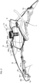
FIG. 2 is a section view of the front hood and the rear hood of the walking-type tilling machine in the embodiment of the present invention, in a state of having been connected and integrated; -
FIG. 3 is a perspective view of the front hood and the rear hood of the walking-type tilling machine in the embodiment of the present invention, before connection and integration; -
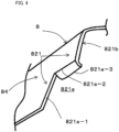
FIG. 4 is a perspective view which shows the left-and-right side-part which is one part of the rear end-part of the front hood ofFIG. 3 ; -
FIG. 5 is a perspective view which shows the left-and-right side-part which is one part of the front end-part of the rear hood ofFIG. 3 ; -
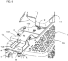
FIG. 6 is a perspective view which shows the structure of the front side of the machine-body, in a state where the front hood and the rear hood of the walking-type tilling machine ofFIG. 1 have been detached; -
FIG. 7 is a perspective view which shows one part of the machine-body ofFIG. 6 ; -
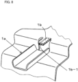
FIG. 8 is a perspective view which shows a variant example of the tongue piece ofFIG. 7 ; -
FIG. 9 is a perspective view which shows a separate variant example of the tongue piece ofFIG. 7 ; -
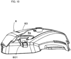
FIG. 10 is a perspective view which shows the lower face of the frontward part of the front hood ofFIG. 2 ; -
FIG. 11 is a perspective view for which one part of the lower face of the frontward part of the front hood ofFIG. 10 has been enlarged; -
FIG. 12 is a perspective view which shows the front hood and the rear hood of the walking-type tilling machine in the embodiment of the present invention, in a state of being going to be connected and integrated; and -
FIG. 13 is a perspective view which shows the front hood and the rear hood of the walking-type tilling machine in the embodiment of the present invention, in a state after having been connected and integrated. -
- 1
- machine-body
- 1a
- second guiding part
- 1a1
- bottom face
- 1a2
- regulating plate
- 1b
- tongue piece
- 1b-1
- elastic body
- 1b-2
- elastic body
- 101
- receiving part stay
- 102
- fuel tank stay
- 2
- transmission case
- 3
- supporting frame
- 4
- traveling vehicle-wheel
- 6
- tilling claw
- 7
- engine
- 70
- muffler cover
- 8
- front hood
- 80
- engaging member
- 80a
- pushing-down part
- 80b
- tip-end side
- 80c
- extendingly-provided portion
- 81
- ceiling part
- 82
- left-and-right side-part
- 821
- rear end-edge
- 821a
- notch part
- 821a-1
- front side-part
- 821a-2
- upper side-part
- 821a-3
- flange part
- 821b
- upper-half part
- 83
- frontward part
- 801
- second guided part
- 801a
- inclining face part
- 84
- rear end-part
- 84a
- rearmost end-edge
- 841
- left-and-right side-part
- 842
- center part
- 842a
- cut
- 9
- rear hood
- 91
- ceiling part
- 92
- rear side-part
- 93
- left-and-right side-part
- 931
- front end-edge
- 931a
- upper-half part
- 932
- guiding face part
- 932a
- upper end-edge
- 933
- left-and-right direction guiding face part
- 94
- frontward part
- 95
- hole
- 96
- front end-part
- 961
- left-and-right side-part
- 96a
- frontmost end-edge
- 962
- center part
- 963
- hole part
- 964
- bottom face
- 10
- handle
- 11
- fuel tank
- 11a
- upper face
- 12
- cap
- 13
- bolt
- 14
- ring nut
- 100
- walking-type tilling machine
- M
- width
- L
- width
- A, B, C, D, E
- bolt
- In the following, while referring to the drawings, the configuration and action of the walking-type tilling machine of one embodiment of the present invention is described.
-
FIG. 1 is a whole-body side view of the walking-type tilling machine in the present embodiment. - In the first place, utilizing
FIG. 1 , descriptions are given regarding the whole-body configuration of a walking-type tilling machine 100 in the present embodiment. - As shown in
FIG. 1 , a machine-body 1 of the walking-type tilling machine 100 has, in the side view, atransmission case 2, and a supportingframe 3 and the like provided at the front side of thetransmission case 2. The axle is protrudingly provided at the lower part of the front side-case which configures thetransmission case 2, a left-and-right pair of traveling vehicle-wheels 4 is rotatably provided and, moreover, the tilling apparatus is configured for which the tilling shaft is protrudingly provided at the lower part of the rear side-case andplural tilling claws 6 are provided. Ahandle 10 is attached to thetransmission case 2. - In
FIG. 1 , thereference numeral 7 is an engine, and an attachable-and-detachablefront hood 8 is being installed thereabove for checking the ignition plug. Thereference numeral 70 is a muffler cover. Thereference numeral 11 is a fuel tank, and arear hood 9 which covers thefuel tank 11 is being installed. Thereference numeral 12 is a cap of thefuel tank 11. - Next, while referring to
FIGs. 2 to 11 , the structure of the aforesaidfront hood 8 andrear hood 9 is described in detail. -
FIG. 2 is a section view centering around thefront hood 8 and therear hood 9 in a state of having been connected and integrated, and thefuel tank 11 in the embodiment of the present invention, andFIG. 3 is a perspective view of thefront hood 8 and therear hood 9 of the walking-type tilling machine in the embodiment of the present invention, before connection and integration. Moreover,FIGs. 4 to 11 are perspective views for which one part of thefront hood 8, one part of therear hood 9, or one part of the machine-body 1 has been enlarged. - The
rear hood 9 is shaped in the form of a rounded box which is configured from aceiling part 91, a rear side-part 92, and left-and-right side-parts 93, and afrontward part 94 thereof is opened, and configures a front end-part 96. - The
rear hood 9 is being fixed to the machine-body 1 with abolt 13, and is being fixed to thefuel tank 11 with aring nut 14. - The
fuel tank 11 is arranged under therear hood 9. Additionally, thereference numeral 95 is a hole formed in abottom face 964 of a mortar-shaped concavity formed at the center of theceiling part 91, and is a place to which thefuel tank 11 is attached. - The front end-
part 96 of theceiling part 91 in therear hood 9 is shaped in a shape for which acenter part 962 frontwardly protrudes with respect to left-and-right side-parts 961. Ahole part 963 is bored at thecenter part 962. Thehole part 963 is an example of one part of the engaging means of the present invention. - Additionally, the front end-
part 96 of theceiling part 91 is an example of the front end-part of the rear hood of the present invention, and the front end-part of the rear hood of the present invention also includes the front end-parts 96 of the left-and-right side-parts 93. - Moreover, as shown in
FIG. 5 , guidingface parts 932 bent toward the inside to be formed are individually provided in the downward parts of front end-edges 931 of the front end-parts 96 of the left-and-right side-parts 93 of therear hood 9. The guidingface parts 932 are examples of the first guiding parts of the present invention. The guidingface part 932 is forming an inclining face which is rising toward the rear direction. As will be described later, this inclining face plays the role of guiding thefront hood 8 while raising thefront hood 8 to the integration position little by little, at the time when thefront hood 8 is connected and integrated. Moreover, an upper end-edge 932a of the guidingface part 932 is a portion which plays the role of supporting thefront hood 8 from below under the state where thefront hood 8 has finished integration. - Further, at the inside edge of the guiding
face part 932, a left-and-right direction guidingface part 933 is provided, which is approximately frontwardly bent to be formed and also has the guiding function. The left-and-right direction guidingface part 933 is being bent a little obliquely toward the inside. As will be described later, the left-and-right direction guidingface part 933 plays the role of guiding thefront hood 8 in such a manner that thefront hood 8 is not shaken in the left-and-right direction, at the time when thefront hood 8 is connected and integrated. At the time thereof, the left-and-right direction guidingface part 933 is being bent a little obliquely toward the inside, and thereby thefront hood 8 is inserted with ease. - On the other hand, the
front hood 8 is shaped in the form of a rounded box which has aceiling part 81, left-and-right side-parts 82 and afrontward part 83. Arearward part 85 thereof is opened, and configures a rear end-part 84. - The rear end-
part 84 of theceiling part 81 in thefront hood 8 is shaped in a shape for which acenter part 842 between left-and-right side-parts 841 thereof is frontwardly drawn. The rear end-part 84 is just shaped in such a shape as corresponds to the front end-part 96 of therear hood 9. - Additionally, the rear end-
part 84 of theceiling part 81 is an example of the rear end-part of the front hood of the present invention, and the rear end-part of the front hood of the present invention also includes the rear end-parts 84 of the left-and-right side-parts 82. - Additionally, a rearmost end-
edge 84a of the rear end-part 84 of theceiling part 81 of thefront hood 8 is configured so as to be, in a state where thefront hood 8 has been connected and integrated, made to get under the lower side (the inside) of a frontmost end-edge 96a of the front end-part 96 of theceiling part 91 of therear hood 9, and be fitted together into the frontmost end-edge 96a. The rearmost end-edge 84a is an example of the one part of the rear end-part of the front hood of the present invention. Moreover, the frontmost end-edge 96a of the front end-part 96 of theceiling part 91 of therear hood 9 is an example of the one part of the front end-part of the rear hood of the present invention. - At the
center part 842 of the rear end-part 84 of theceiling part 81 of thefront hood 8, an engagingmember 80 extendingly provided rearwardly from the edge thereof and formed is provided. As shown inFIG. 2 , one part of an extendingly-providedportion 80c of the engagingmember 80 is flexed. By this, elasticity is given. A pushing-downpart 80a which has the shape of a convex part is formed at the rear end of the engagingmember 80, and the shape of this convex part corresponds to the shape of theaforesaid hole part 963 of therear hood 9. The pushing-downpart 80a and thehole part 963 are examples of the engaging means of the present invention. - Further, as shown in
FIG. 3 , at the position of the edge of thecenter part 842, where the root of the engagingmember 80 is extendingly provided and formed,cuts 842a are boringly provided individually at left-and-right two spots, and the engagingmember 80 deflects with ease in the up-and-down direction with elastic force. - Additionally, even in a case of having, as a variant example, provided an engaging member at the
rear hood 9 side and provided a hole part at thefront hood 8 side, it is desirable that cuts should be formed at left-and-right two spots of the root of the engaging member of therear hood 9 side. - Moreover, as shown in
FIG. 2 , the design is such that, at the time when the pushing-downpart 80a is pushed down from above by a finger, while opening up a predetermined additional space, an upper face 11a of theaforesaid fuel tank 11 is positioned therebelow. By this, when the pushing-downpart 80a is pushed down by a finger, the pushing-downpart 80a abuts against the upper face 11a of thefuel tank 11 below even if strongly pushing in excess, and thereby such an accident can be prevented that the pushing-downpart 80a is broken with pushing-down in excess. - Additionally, also in a case where, as a variant example, an engaging member is provided at the
rear hood 9 side, it is desirable that, as a stopper at the time of pushing-down thereof, the upper face 11a of thefuel tank 11 should function. - Additionally, a tip-
end side 80b of the pushing-downpart 80a is shaped like a taper and, at the time when thefront hood 8 is connected and integrated, the pushing-downpart 80a abuts onto the edge of thecenter part 962 of the front end-part 96 of therear hood 9, and gets thereunder with ease. - On the other hand, as shown in
FIGs. 3 and4 , in individual rear end-edges 821 of the left-and-right side-parts 82 of thefront hood 8,frontward notch parts 821a are formed in the lower half. A front side-part 821a-1 of thenotch part 821a is inclining, and the frontward cut thereof becomes deeper as downwardly going. The degree of this inclining corresponds to the inclining of the aforedescribed guidingface part 932 of therear hood 9. - Moreover, a
flange part 821a-3 is bent toward the inside and formed at an upper side-part 821a-2 of thenotch part 821a. Theflange part 821a-3 mounts, in a state where thefront hood 8 has been connected and integrated, on the upper end-edge 932a of the guidingface part 932 of therear hood 9, and the upper end-edge 932a supports theflange part 821a-3. By this, therear hood 9 supports thefront hood 8. - The front side-
part 821a-1, the upper side-part 821a-2 and theflange part 821a-3 of theaforesaid notch part 821a are examples of the first guided parts of the present invention. - Further, in a state where the
front hood 8 has been connected and integrated, the guidingface part 932 and the left-and-right direction guidingface part 933 of therear hood 9 are positioned in the inside of the front side-part 821a-1 of thenotch part 821a of thefront hood 8. The front side-part 821a-1 of thenotch part 821a of the rear end-part 84 of thefront hood 8 is an example of the another one part of the rear end-part of the front hood of the present invention. Moreover, the guidingface part 932 and the left-and-right direction guidingface part 933 of the front end-part 96 of therear hood 9 are examples of the another one part of the front end-part of the rear hood of the present invention. - Further, the
flange part 821a-3 of thefront hood 8 abuts, at the time when thefront hood 8 is connected and integrated, against the aforedescribed left-and-right direction guidingface part 933 of therear hood 9, and is thereby guided so as not to be shaken in the left-and-right direction. - Moreover, the state becomes such that upper-
half parts 821b of the individual rear end-edges 821 of the left-and-right side-parts 82 of thefront hood 8 have been, in a case of having connected and integrated thefront hood 8, inserted and fitted together into the insides of upper-half parts 931a of the front end-edges 931 of the left-and-right side-parts 93 of therear hood 9. By this, after connection and integration, motion of thefront hood 8 in the left-and-right direction is regulated. The upper-half part 821b of the rear end-edge 821 of thefront hood 8 is an example of the one part of the rear end-part of the front hood of the present invention. Moreover, the upper-half part 931a of the front end-edge 931 of therear hood 9 is an example of the one part of the front end-part of the rear hood of the present invention. - Next, descriptions are given regarding the connection structure of the
frontward part 83 of thefront hood 8 to the machine-body 1. - In
FIG. 6 , a second guiding part 1a is provided in a receivingpart stay 101 which is one part of the machine-body 1. The receivingpart stay 101 is being set to theengine 7 by bolts A, B and C. Moreover, the front part of thefuel tank 11 is, by a bolt D, being fixed to a fuel tank stay 102 which is one part of the machine-body 1. Further, the front part of themuffler cover 70 is being fixed to the receivingpart stay 101 by a bolt E. - Detailed descriptions are given in the following regarding the second guiding part 1a. In
FIGs. 2 ,6 and7 , as aforedescribed, the second guiding part 1a is provided in the machine-body 1. That is to say, in one part of the machine-body 1 which is positioned below thefrontward part 83 of thefront hood 8 in a state where thefront hood 8 has been connected and integrated, the second guiding part 1a is provided. - The second guiding part 1a is in a sectional U-shape of the upward orientation and is extending long in the front-and-rear direction. The reference numeral 1a1 is a bottom face thereof, and the reference numerals 1a2 are regulating plates standingly provided at both sides of the bottom face 1a1. In addition, the regulating plates 1a2 of both sides are standingly provided in such a manner that upward spacing becomes broader than downward spacing. By this, when the
front hood 8 is lowered from above oncomingly, a second guidedpart 801 of thefront hood 8 described later enters with ease. - More desirably, the regulating plates 1a2 of both sides should be opened in such a manner that frontward spacing becomes broader than rearward spacing. This is because the
front hood 8 is made to enter from above with more ease. - Further, in another one part of the machine-
body 1 which is positioned behind the second guiding part 1a, atongue piece 1b with elasticity more or less given is provided in a shape which frontwardly protrudes. -
FIG. 8 is a variant example of thetongue piece 1b, and anelastic body 1b-1 is stuck on the lower side. As will be described later, in a case of having pressed thefront hood 8, up-and-down vibration thereof can be restrained by the existence of theelastic body 1b-1. -
FIG. 9 is further a variant example of thetongue piece 1b, and anelastic body 1b-2 is fitted to the circumference. In a case of having pressed thefront hood 8, up-and-down vibration thereof can be restrained also in this case. - On the other hand, as shown in
FIG. 10 , to the lower face (the inner face) 8a of thefrontward part 83 of thefront hood 8, the second guidedpart 801 is being set under the state of downwardly protruding in rear oblique orientation.FIG. 11 is a view for which the second guidedpart 801 has been enlarged. As shown inFIG. 11 , the second guidedpart 801 is shaped in a shape for which a width L of the lower end-part thereof is a little narrower than a width M of the aforesaid second guiding part 1a and, at the time when thefront hood 8 is connected and integrated, the second guidedpart 801 can slide while mounting on the second guiding part 1a. The vertical section of the lower end-part is shaped in an approximately right-angled shape, and the second guidedpart 801 mounts on the second guiding part 1a with ease. - Moreover, the regulating plate 1a2 has the function of preventing lateral shaking at the time of sliding thereof.
- Further, the upper face of the lower end-part of the second guided
part 801, namely the face which faces on thelower face 8a side of thefront hood 8 is forming an incliningface part 801a which is downwardly inclining in rear oblique orientation. - As will be described later, under the state where the
front hood 8 has been connected and integrated, theaforesaid tongue piece 1b mounts onto the incliningface part 801a, thetongue piece 1b presses down the incliningface part 801a, and uplifting of thefrontward part 83 of thefront hood 8 is being prevented. - Next, the process of connecting and integrating the
front hood 8 with therear hood 9 is described in accordance withFIGs. 2 ,3 ,12 and13 . - In the first place, as shown in
FIG. 3 , thefront hood 8 is held with both hands, and thefront hood 8 is inserted into therear hood 9 side ongoingly, under such a state that the rear end-part 84 thereof gets under the lower side of the front end-part 96 of therear hood 9, and besides, under such a state that the upper side-parts 821a-2, or alternatively theflange parts 821a-3 of thenotch parts 821a, which exist at the left-and-right both sides, abut onto the guidingface parts 932, or alternatively the left-and-right direction guidingface parts 933 of therear hood 9. - It is desirable that the size and the shape should be designed beforehand in such a manner that, at the time thereof, before the pushing-down
part 80a of the engagingmember 80 of the rear end-part 84 of thefront hood 8 reaches the front end-part 96 of therear hood 9, the upper side-parts 821a-2 and theflange parts 821a-3 of thenotch parts 821a of thefront hood 8 abut onto the guidingface parts 932 and the left-and-right direction guidingface parts 933 of therear hood 9. By this, without shaking in the left-and-right direction, assembling becomes easy. - Additionally, even in a case of having, as a variant example, provided notch parts at the
rear hood 9 side and provided guiding face parts and left-and-right direction guiding face parts at thefront hood 8 side, it is desirable that the size and the shape should be similarly designed. - At the time thereof the design is such that, as aforedescribed, the lower end of the second guided
part 801 of the lower face of thefront hood 8 mounts on the second guiding part 1a which is provided at the machine-body 1 side, and is supported. - Next, as shown in
FIG. 12 , when thefront hood 8 is further moved to therear hood 9 side, since the rear end-part 84 of thefront hood 8 is moved at a position which is a little lower than the position of the front end-part 96 of therear hood 9, then the pushing-downpart 80a of the engagingmember 80 of thefront hood 8 gets under the lower side of the frontmost end-edge 96a of therear hood 9 while deflecting with elastic force. - At the time thereof, the upper side-
parts 821a-2 and theflange parts 821a-3 of theaforesaid notch parts 821a abut onto the guidingface parts 932 of therear hood 9, further rise ongoingly while abutting along the inclining faces thereof, and mount onto the upper end-edges 932a of therear hood 9. - Moreover, at the time thereof, depending on the way of holding the
front hood 8, the front side-parts 821a-1 of thenotch parts 821a of thefront hood 8, and the upper side-parts 821a-2 and theflange parts 821a-3 of theaforesaid notch parts 821a abut onto the left-and-right direction guidingface parts 933 of therear hood 9, and are thereby guided so as not to be shaken in the left-and-right direction. - Further, at the time thereof, the lower end of the second guided
part 801 of the lower face of thefront hood 8 mounts continuously on the second guiding part 1a which is provided at the machine-body 1 side and slides ongoingly while further being rearwardly guided. At the time thereof, the regulating plate 1a2 prevents lateral shaking of thefront hood 8 at the time of sliding thereof. - Next, as shown in
FIG. 13 , thefront hood 8 is further pushed into therear hood 9. As a result, the engagingmember 80 of thefront hood 8 reaches the position of thehole part 963 of therear hood 9, upwardly rises by elastic force thereof, and fits into thehole part 963. After the engagingmember 80 fitting into thehole part 963, by energizing force of the engagingmember 80, coming-out of the engagingmember 80 can be prevented. - At the same time, the front side-
parts 821a-1 of thenotch parts 821a of thefront hood 8 abut against the guidingface parts 932 of therear hood 9, and thefront hood 8 is not rearwardly pushed into therear hood 9 anymore. Moreover, under this state, as aforedescribed, the state becomes such that the upper side-parts 821a-2 and theflange parts 821a-3 of thenotch parts 821a have been supported by the upper end-edges 932a of therear hood 9. - Further, at the same time, as shown in
FIG. 2 , since at a place which is positioned behind the second guiding part 1a, thetongue piece 1b with elasticity given is provided in a shape which frontwardly protrudes, thetongue piece 1b mounts onto the incliningface part 801a of the upper face of the lower end-part of the second guidedpart 801 of the lower face of thefront hood 8, which has mounted continuously on the second guiding part 1a of the machine-body 1 and slid oncomingly, thetongue piece 1b presses down the incliningface part 801a, and uplifting of thefrontward part 83 of thefront hood 8 is prevented. - Like this, the state becomes such that the
front hood 8 has been connected with therear hood 9, and been firmly set also to the machine-body 1. - As a result, since the
reciprocal hoods - Moreover, under the state where the
front hood 8 has been connected and integrated, since the engagingmember 80 which is a convex part of thefront hood 8 is fitting into thehole part 963 of therear hood 9, there is no worry about position deviation in the front-and-rear direction. - Additionally, in contrast, it is also permitted that a hole is provided at the
front hood 8, and that a convex part is provided at therear hood 9. In this case, it is desirable that thefront hood 8 should come above therear hood 9. - Additionally, in a case of detaching the
front hood 8 from therear hood 9, while pushing down the engagingmember 80 by a finger, thefront hood 8 is frontwardly drawn out. Even under the state where theaforesaid tongue piece 1b is pressurizing the incliningface part 801a, since the incliningface part 801a is an inclining face which is rising toward the front direction, the engagingmember 80 smoothly gets apart when being frontwardly drawn out. - Moreover, as another embodiment, in contrast, it is also permitted that, in the upper face and the upper half of the side-part, the
rear hood 9 goes into the inside of thefront hood 8 and that, in the lower half of the side-part, therear hood 9 comes to the outside of thefront hood 8. Also like this, adjustment at the time of assembling becomes unnecessary. Moreover, in the side-part, since thefront hood 8 and therear hood 9 go into each other in such a manner that the overlapping relationship is reversed halfway, the upper end-edge 932a of therear hood 9 supports the upper side-part 821a-2 of thenotch part 821a of thefront hood 8. Like this, thefront hood 8 and therear hood 9 may go into each other in the side-part in such a manner that the overlapping relationship interchanges halfway. By this, uplifting of the rear end of the front hood after assembling can be prevented. - Moreover, since the engaging
member 80 is being upwardly energized with elastic force, coming-out of the convex part of the pushing-downpart 80a from thehole part 963 can be prevented. Moreover, as aforedescribed, even in a case where the relationship between the convex part and the hole part of thefront hood 8 and therear hood 9 is reversed, coming-out can be prevented with elasticity being given. - Moreover, it is desirable that the engaging
member 80 of thefront hood 8 should be positioned at the center of the machine-body 1, with reference to the left-and-right direction. By this, restraining effect of the deviation prevention in the left-and-right direction is exerted equally in the left-and-right direction, and the assembling position is stabilized. Moreover, also in a case of having provided in contrast an engaging member at therear hood 9 side, it is desirable that the engaging member should be positioned at the center of the machine-body 1 with reference to the left-and-right direction. - Moreover, two engaging
members 80 of thefront hood 8 can also be provided and, in this case, the engagingmembers 80 are installed so as to become symmetric in the left-and-right direction, with respect to the center of the machine-body 1 with reference to the left-and-right direction. Connection and integration becomes stronger and, what is more, balance in the left-and-right direction can be kept. Moreover, also in a case of having provided in contrast two engaging members at therear hood 9 side, the engaging members are installed so as to become symmetric in the left-and-right direction, with respect to the center with reference to the left-and-right direction. - Moreover, in a case where, as a variant example, a rearward protruding part (a guiding face part) is formed at the
front hood 8 side, and a notch part is provided at therear hood 9 side, the rearward protruding part of thefront hood 8 becomes a guide at the time of inserting in the side-part side from the upper face of therear hood 9. - Moreover, as a variant example, structure is also realizable, for which a second guided part is provided at the front side of the machine-
body 1 and a second guiding part is provided in the lower face (the inner face) of thefront hood 8. - Also in a variant example like this, it is desirable that the second guiding part should be in a sectional U-shape of the downward orientation and extend long in the front-and-rear direction, that regulating plates should be formed at both sides, that downward spacing should become broader than upward spacing, and that frontward spacing should become broader than rearward spacing. Moreover, the section of the upper end-part of the second guided part of the machine-
body 1 is shaped in an approximately right-angled shape, and the second guided part mounts on the second guiding part with ease. - A walking-type tilling machine pertaining to the present invention has an effect that troublesomeness for adjustment of a gap and a distance between the front cover and the rear cover is not necessitated, and is useful as a walking-type tilling machine.
Claims (2)
- A walking-type tilling machine (100), comprising:a travelling vehicle-wheel;an operating handle arranged behind the travelling vehicle-wheel;a tilling claw which tills a farm field;an engine (7) which rotates the travelling vehicle-wheel and the tilling claw,a front hood (8) and a rear hood (9), which cover the engine from above,wherein the rear hood is fixed to a machine-body (1) by fixing means, and the front hood is being connected with the rear hood,wherein in a state where the front hood is being connected with the rear hood, one part of the front hood is going into an inside of one part of the rear hood, and another one part of the rear hood is going into an inside of another one part of the front hood,wherein in a state where the front hood is being connected with the rear hood, one part of a rear end-part (84) of the front hood is going into an inside of one part of a front end-part (96) of the rear hood, and another one part of the front end-part of the rear hood is going into an inside of another one part of the rear end-part of the front hood,wherein the front hood is being connected with the rear hood by engaging means (80a, 963),wherein the rear end-part of the front hood is being connected with the front end-part of the rear hood by engaging means (80a, 963),wherein the engaging means are configured with a convex part (80a) of the front hood side, and a hole part (963) of the rear hood side,wherein there are provided at left-and-right both side-parts of the front end-part (96) of the rear hood, first guiding parts (932) which guide left-and-right both side-parts of the rear end-part (84) of the front hood are individually formed,wherein when the front hood is connected with the rear hood, by the individual first guiding parts, individual first guided parts (82Ia-I, 821a-2, 821a-3) of the left-and-right both side-parts of the rear end-part of the front hood are guided and further, in a state where the front hood is being connected with the rear hood, the individual first guiding parts support the front hood.
- The walking-type tilling machine according to claim 1, whereina second guided part (801) is provided at any one of one part of the machine-body and a lower face of the front hood, said one part being positioned below a frontward part of the front hood in a state where the front hood is being connected with the rear hood, and a second guiding part (1a) which guides the second guided part is provided at another one,when the front hood is connected with the rear hood, the second guided part is guided oy the second guiding part.
Applications Claiming Priority (1)
| Application Number | Priority Date | Filing Date | Title |
|---|---|---|---|
| JP2019082214A JP7059977B2 (en) | 2019-04-23 | 2019-04-23 | Walking cultivator |
Publications (2)
| Publication Number | Publication Date |
|---|---|
| EP3729929A1 EP3729929A1 (en) | 2020-10-28 |
| EP3729929B1 true EP3729929B1 (en) | 2024-07-03 |
Family
ID=68944469
Family Applications (1)
| Application Number | Title | Priority Date | Filing Date |
|---|---|---|---|
| EP19217263.3A Active EP3729929B1 (en) | 2019-04-23 | 2019-12-17 | Walking-type tilling machine |
Country Status (2)
| Country | Link |
|---|---|
| EP (1) | EP3729929B1 (en) |
| JP (2) | JP7059977B2 (en) |
Family Cites Families (9)
| Publication number | Priority date | Publication date | Assignee | Title |
|---|---|---|---|---|
| JPS4951718U (en) * | 1972-08-23 | 1974-05-08 | ||
| JPH0448642Y2 (en) * | 1987-04-11 | 1992-11-17 | ||
| JPH11113305A (en) * | 1997-10-14 | 1999-04-27 | Mitsubishi Agricult Mach Co Ltd | Detaching device for rear cover-closing plate in rotary cultural working machine |
| US7237620B2 (en) | 2002-03-11 | 2007-07-03 | Desa Ip, Llc | Electric garden tiller |
| JP4439528B2 (en) * | 2007-03-06 | 2010-03-24 | ヤンマー株式会社 | Walking type management machine |
| JP2011089450A (en) | 2009-10-21 | 2011-05-06 | Mitsubishi Agricult Mach Co Ltd | Walking-type movable agricultural machine |
| JP5980163B2 (en) | 2013-05-07 | 2016-08-31 | 株式会社クボタ | Walking type work machine |
| JP6108954B2 (en) | 2013-05-21 | 2017-04-05 | 株式会社クボタ | Walking type work machine |
| JP6128250B1 (en) * | 2016-03-29 | 2017-05-17 | 井関農機株式会社 | Walk-type field cultivator |
-
2019
- 2019-04-23 JP JP2019082214A patent/JP7059977B2/en active Active
- 2019-12-17 EP EP19217263.3A patent/EP3729929B1/en active Active
-
2021
- 2021-09-30 JP JP2021161434A patent/JP7164002B2/en active Active
Also Published As
| Publication number | Publication date |
|---|---|
| JP2021192646A (en) | 2021-12-23 |
| JP2020178574A (en) | 2020-11-05 |
| EP3729929A1 (en) | 2020-10-28 |
| JP7059977B2 (en) | 2022-04-26 |
| JP7164002B2 (en) | 2022-11-01 |
Similar Documents
| Publication | Publication Date | Title |
|---|---|---|
| EP3081419A1 (en) | Working vehicle | |
| EP4541663B1 (en) | Attaching member, combination of attaching member and attached member, and vehicle | |
| EP2143584A1 (en) | Vehicular Canister Mounting Structure | |
| EP1780400B1 (en) | Fuel pump mounting structural body | |
| US11104382B2 (en) | Vehicle rear structure | |
| JP2020032930A (en) | vehicle | |
| EP3729929A1 (en) | Walking-type tilling machine | |
| EP3620355A1 (en) | Vehicle body structure | |
| CN109927792B (en) | Structure for front part of vehicle body | |
| CN110949521A (en) | Front subframe structure | |
| CN110316300B (en) | Side cover structure of straddle-type vehicle | |
| EP3470310B1 (en) | Working vehicle | |
| CN109927794B (en) | Structure for front part of vehicle body | |
| CN109866829B (en) | Front body structure | |
| EP2011673A2 (en) | Vibration damping device and manufacturing method thereof | |
| JP3779001B2 (en) | Tractor front cover attachment / detachment structure | |
| KR101685395B1 (en) | Mounting unit for sub-frame in vehicles | |
| JP6255761B2 (en) | Motorcycle tank cover support structure | |
| EP2017174A1 (en) | Straddle type vehicle | |
| CN112789215A (en) | Vehicle body structure of vehicle | |
| CN108622303B (en) | Front chain shifter for bicycle | |
| EP4477510A1 (en) | Support structure for turn signal lamp | |
| JP2012131464A (en) | Vehicle seat | |
| CN110641560B (en) | Rear floor structure of vehicle body | |
| CN114905941B (en) | Opening and closing parts |
Legal Events
| Date | Code | Title | Description |
|---|---|---|---|
| PUAI | Public reference made under article 153(3) epc to a published international application that has entered the european phase |
Free format text: ORIGINAL CODE: 0009012 |
|
| STAA | Information on the status of an ep patent application or granted ep patent |
Free format text: STATUS: THE APPLICATION HAS BEEN PUBLISHED |
|
| AK | Designated contracting states |
Kind code of ref document: A1 Designated state(s): AL AT BE BG CH CY CZ DE DK EE ES FI FR GB GR HR HU IE IS IT LI LT LU LV MC MK MT NL NO PL PT RO RS SE SI SK SM TR |
|
| AX | Request for extension of the european patent |
Extension state: BA ME |
|
| STAA | Information on the status of an ep patent application or granted ep patent |
Free format text: STATUS: REQUEST FOR EXAMINATION WAS MADE |
|
| 17P | Request for examination filed |
Effective date: 20210416 |
|
| RBV | Designated contracting states (corrected) |
Designated state(s): AL AT BE BG CH CY CZ DE DK EE ES FI FR GB GR HR HU IE IS IT LI LT LU LV MC MK MT NL NO PL PT RO RS SE SI SK SM TR |
|
| STAA | Information on the status of an ep patent application or granted ep patent |
Free format text: STATUS: EXAMINATION IS IN PROGRESS |
|
| 17Q | First examination report despatched |
Effective date: 20230102 |
|
| GRAP | Despatch of communication of intention to grant a patent |
Free format text: ORIGINAL CODE: EPIDOSNIGR1 |
|
| STAA | Information on the status of an ep patent application or granted ep patent |
Free format text: STATUS: GRANT OF PATENT IS INTENDED |
|
| INTG | Intention to grant announced |
Effective date: 20240213 |
|
| GRAS | Grant fee paid |
Free format text: ORIGINAL CODE: EPIDOSNIGR3 |
|
| GRAA | (expected) grant |
Free format text: ORIGINAL CODE: 0009210 |
|
| STAA | Information on the status of an ep patent application or granted ep patent |
Free format text: STATUS: THE PATENT HAS BEEN GRANTED |
|
| P01 | Opt-out of the competence of the unified patent court (upc) registered |
Effective date: 20240501 |
|
| AK | Designated contracting states |
Kind code of ref document: B1 Designated state(s): AL AT BE BG CH CY CZ DE DK EE ES FI FR GB GR HR HU IE IS IT LI LT LU LV MC MK MT NL NO PL PT RO RS SE SI SK SM TR |
|
| REG | Reference to a national code |
Ref country code: CH Ref legal event code: EP |
|
| REG | Reference to a national code |
Ref country code: DE Ref legal event code: R096 Ref document number: 602019054516 Country of ref document: DE |
|
| REG | Reference to a national code |
Ref country code: LT Ref legal event code: MG9D |
|
| REG | Reference to a national code |
Ref country code: NL Ref legal event code: MP Effective date: 20240703 |
|
| PG25 | Lapsed in a contracting state [announced via postgrant information from national office to epo] |
Ref country code: PT Free format text: LAPSE BECAUSE OF FAILURE TO SUBMIT A TRANSLATION OF THE DESCRIPTION OR TO PAY THE FEE WITHIN THE PRESCRIBED TIME-LIMIT Effective date: 20241104 |
|
| REG | Reference to a national code |
Ref country code: AT Ref legal event code: MK05 Ref document number: 1698785 Country of ref document: AT Kind code of ref document: T Effective date: 20240703 |
|
| PG25 | Lapsed in a contracting state [announced via postgrant information from national office to epo] |
Ref country code: NL Free format text: LAPSE BECAUSE OF FAILURE TO SUBMIT A TRANSLATION OF THE DESCRIPTION OR TO PAY THE FEE WITHIN THE PRESCRIBED TIME-LIMIT Effective date: 20240703 |
|
| PG25 | Lapsed in a contracting state [announced via postgrant information from national office to epo] |
Ref country code: PT Free format text: LAPSE BECAUSE OF FAILURE TO SUBMIT A TRANSLATION OF THE DESCRIPTION OR TO PAY THE FEE WITHIN THE PRESCRIBED TIME-LIMIT Effective date: 20241104 Ref country code: NL Free format text: LAPSE BECAUSE OF FAILURE TO SUBMIT A TRANSLATION OF THE DESCRIPTION OR TO PAY THE FEE WITHIN THE PRESCRIBED TIME-LIMIT Effective date: 20240703 |
|
| PG25 | Lapsed in a contracting state [announced via postgrant information from national office to epo] |
Ref country code: NO Free format text: LAPSE BECAUSE OF FAILURE TO SUBMIT A TRANSLATION OF THE DESCRIPTION OR TO PAY THE FEE WITHIN THE PRESCRIBED TIME-LIMIT Effective date: 20241003 |
|
| PG25 | Lapsed in a contracting state [announced via postgrant information from national office to epo] |
Ref country code: FI Free format text: LAPSE BECAUSE OF FAILURE TO SUBMIT A TRANSLATION OF THE DESCRIPTION OR TO PAY THE FEE WITHIN THE PRESCRIBED TIME-LIMIT Effective date: 20240703 Ref country code: GR Free format text: LAPSE BECAUSE OF FAILURE TO SUBMIT A TRANSLATION OF THE DESCRIPTION OR TO PAY THE FEE WITHIN THE PRESCRIBED TIME-LIMIT Effective date: 20241004 Ref country code: PL Free format text: LAPSE BECAUSE OF FAILURE TO SUBMIT A TRANSLATION OF THE DESCRIPTION OR TO PAY THE FEE WITHIN THE PRESCRIBED TIME-LIMIT Effective date: 20240703 |
|
| PG25 | Lapsed in a contracting state [announced via postgrant information from national office to epo] |
Ref country code: BG Free format text: LAPSE BECAUSE OF FAILURE TO SUBMIT A TRANSLATION OF THE DESCRIPTION OR TO PAY THE FEE WITHIN THE PRESCRIBED TIME-LIMIT Effective date: 20240703 |
|
| PG25 | Lapsed in a contracting state [announced via postgrant information from national office to epo] |
Ref country code: LV Free format text: LAPSE BECAUSE OF FAILURE TO SUBMIT A TRANSLATION OF THE DESCRIPTION OR TO PAY THE FEE WITHIN THE PRESCRIBED TIME-LIMIT Effective date: 20240703 |
|
| PG25 | Lapsed in a contracting state [announced via postgrant information from national office to epo] |
Ref country code: AT Free format text: LAPSE BECAUSE OF FAILURE TO SUBMIT A TRANSLATION OF THE DESCRIPTION OR TO PAY THE FEE WITHIN THE PRESCRIBED TIME-LIMIT Effective date: 20240703 Ref country code: IS Free format text: LAPSE BECAUSE OF FAILURE TO SUBMIT A TRANSLATION OF THE DESCRIPTION OR TO PAY THE FEE WITHIN THE PRESCRIBED TIME-LIMIT Effective date: 20241103 |
|
| PG25 | Lapsed in a contracting state [announced via postgrant information from national office to epo] |
Ref country code: HR Free format text: LAPSE BECAUSE OF FAILURE TO SUBMIT A TRANSLATION OF THE DESCRIPTION OR TO PAY THE FEE WITHIN THE PRESCRIBED TIME-LIMIT Effective date: 20240703 Ref country code: CZ Free format text: LAPSE BECAUSE OF FAILURE TO SUBMIT A TRANSLATION OF THE DESCRIPTION OR TO PAY THE FEE WITHIN THE PRESCRIBED TIME-LIMIT Effective date: 20240703 |
|
| PG25 | Lapsed in a contracting state [announced via postgrant information from national office to epo] |
Ref country code: ES Free format text: LAPSE BECAUSE OF FAILURE TO SUBMIT A TRANSLATION OF THE DESCRIPTION OR TO PAY THE FEE WITHIN THE PRESCRIBED TIME-LIMIT Effective date: 20240703 Ref country code: RS Free format text: LAPSE BECAUSE OF FAILURE TO SUBMIT A TRANSLATION OF THE DESCRIPTION OR TO PAY THE FEE WITHIN THE PRESCRIBED TIME-LIMIT Effective date: 20241003 |
|
| PG25 | Lapsed in a contracting state [announced via postgrant information from national office to epo] |
Ref country code: RS Free format text: LAPSE BECAUSE OF FAILURE TO SUBMIT A TRANSLATION OF THE DESCRIPTION OR TO PAY THE FEE WITHIN THE PRESCRIBED TIME-LIMIT Effective date: 20241003 Ref country code: PL Free format text: LAPSE BECAUSE OF FAILURE TO SUBMIT A TRANSLATION OF THE DESCRIPTION OR TO PAY THE FEE WITHIN THE PRESCRIBED TIME-LIMIT Effective date: 20240703 Ref country code: NO Free format text: LAPSE BECAUSE OF FAILURE TO SUBMIT A TRANSLATION OF THE DESCRIPTION OR TO PAY THE FEE WITHIN THE PRESCRIBED TIME-LIMIT Effective date: 20241003 Ref country code: LV Free format text: LAPSE BECAUSE OF FAILURE TO SUBMIT A TRANSLATION OF THE DESCRIPTION OR TO PAY THE FEE WITHIN THE PRESCRIBED TIME-LIMIT Effective date: 20240703 Ref country code: IS Free format text: LAPSE BECAUSE OF FAILURE TO SUBMIT A TRANSLATION OF THE DESCRIPTION OR TO PAY THE FEE WITHIN THE PRESCRIBED TIME-LIMIT Effective date: 20241103 Ref country code: HR Free format text: LAPSE BECAUSE OF FAILURE TO SUBMIT A TRANSLATION OF THE DESCRIPTION OR TO PAY THE FEE WITHIN THE PRESCRIBED TIME-LIMIT Effective date: 20240703 Ref country code: GR Free format text: LAPSE BECAUSE OF FAILURE TO SUBMIT A TRANSLATION OF THE DESCRIPTION OR TO PAY THE FEE WITHIN THE PRESCRIBED TIME-LIMIT Effective date: 20241004 Ref country code: FI Free format text: LAPSE BECAUSE OF FAILURE TO SUBMIT A TRANSLATION OF THE DESCRIPTION OR TO PAY THE FEE WITHIN THE PRESCRIBED TIME-LIMIT Effective date: 20240703 Ref country code: ES Free format text: LAPSE BECAUSE OF FAILURE TO SUBMIT A TRANSLATION OF THE DESCRIPTION OR TO PAY THE FEE WITHIN THE PRESCRIBED TIME-LIMIT Effective date: 20240703 Ref country code: CZ Free format text: LAPSE BECAUSE OF FAILURE TO SUBMIT A TRANSLATION OF THE DESCRIPTION OR TO PAY THE FEE WITHIN THE PRESCRIBED TIME-LIMIT Effective date: 20240703 Ref country code: BG Free format text: LAPSE BECAUSE OF FAILURE TO SUBMIT A TRANSLATION OF THE DESCRIPTION OR TO PAY THE FEE WITHIN THE PRESCRIBED TIME-LIMIT Effective date: 20240703 Ref country code: AT Free format text: LAPSE BECAUSE OF FAILURE TO SUBMIT A TRANSLATION OF THE DESCRIPTION OR TO PAY THE FEE WITHIN THE PRESCRIBED TIME-LIMIT Effective date: 20240703 |
|
| REG | Reference to a national code |
Ref country code: DE Ref legal event code: R097 Ref document number: 602019054516 Country of ref document: DE |
|
| PG25 | Lapsed in a contracting state [announced via postgrant information from national office to epo] |
Ref country code: SM Free format text: LAPSE BECAUSE OF FAILURE TO SUBMIT A TRANSLATION OF THE DESCRIPTION OR TO PAY THE FEE WITHIN THE PRESCRIBED TIME-LIMIT Effective date: 20240703 Ref country code: DK Free format text: LAPSE BECAUSE OF FAILURE TO SUBMIT A TRANSLATION OF THE DESCRIPTION OR TO PAY THE FEE WITHIN THE PRESCRIBED TIME-LIMIT Effective date: 20240703 Ref country code: RO Free format text: LAPSE BECAUSE OF FAILURE TO SUBMIT A TRANSLATION OF THE DESCRIPTION OR TO PAY THE FEE WITHIN THE PRESCRIBED TIME-LIMIT Effective date: 20240703 |
|
| PG25 | Lapsed in a contracting state [announced via postgrant information from national office to epo] |
Ref country code: EE Free format text: LAPSE BECAUSE OF FAILURE TO SUBMIT A TRANSLATION OF THE DESCRIPTION OR TO PAY THE FEE WITHIN THE PRESCRIBED TIME-LIMIT Effective date: 20240703 |
|
| PG25 | Lapsed in a contracting state [announced via postgrant information from national office to epo] |
Ref country code: SK Free format text: LAPSE BECAUSE OF FAILURE TO SUBMIT A TRANSLATION OF THE DESCRIPTION OR TO PAY THE FEE WITHIN THE PRESCRIBED TIME-LIMIT Effective date: 20240703 Ref country code: IT Free format text: LAPSE BECAUSE OF FAILURE TO SUBMIT A TRANSLATION OF THE DESCRIPTION OR TO PAY THE FEE WITHIN THE PRESCRIBED TIME-LIMIT Effective date: 20240703 |
|
| PLBE | No opposition filed within time limit |
Free format text: ORIGINAL CODE: 0009261 |
|
| STAA | Information on the status of an ep patent application or granted ep patent |
Free format text: STATUS: NO OPPOSITION FILED WITHIN TIME LIMIT |
|
| 26N | No opposition filed |
Effective date: 20250404 |
|
| PG25 | Lapsed in a contracting state [announced via postgrant information from national office to epo] |
Ref country code: MC Free format text: LAPSE BECAUSE OF FAILURE TO SUBMIT A TRANSLATION OF THE DESCRIPTION OR TO PAY THE FEE WITHIN THE PRESCRIBED TIME-LIMIT Effective date: 20240703 |
|
| REG | Reference to a national code |
Ref country code: CH Ref legal event code: PL |
|
| PG25 | Lapsed in a contracting state [announced via postgrant information from national office to epo] |
Ref country code: LU Free format text: LAPSE BECAUSE OF NON-PAYMENT OF DUE FEES Effective date: 20241217 |
|
| GBPC | Gb: european patent ceased through non-payment of renewal fee |
Effective date: 20241217 |
|
| PG25 | Lapsed in a contracting state [announced via postgrant information from national office to epo] |
Ref country code: SE Free format text: LAPSE BECAUSE OF FAILURE TO SUBMIT A TRANSLATION OF THE DESCRIPTION OR TO PAY THE FEE WITHIN THE PRESCRIBED TIME-LIMIT Effective date: 20240703 |
|
| PG25 | Lapsed in a contracting state [announced via postgrant information from national office to epo] |
Ref country code: GB Free format text: LAPSE BECAUSE OF NON-PAYMENT OF DUE FEES Effective date: 20241217 |
|
| PG25 | Lapsed in a contracting state [announced via postgrant information from national office to epo] |
Ref country code: CH Free format text: LAPSE BECAUSE OF NON-PAYMENT OF DUE FEES Effective date: 20241231 |
|
| PG25 | Lapsed in a contracting state [announced via postgrant information from national office to epo] |
Ref country code: IE Free format text: LAPSE BECAUSE OF NON-PAYMENT OF DUE FEES Effective date: 20241217 |
|
| PGFP | Annual fee paid to national office [announced via postgrant information from national office to epo] |
Ref country code: DE Payment date: 20251128 Year of fee payment: 7 |
|
| PGFP | Annual fee paid to national office [announced via postgrant information from national office to epo] |
Ref country code: FR Payment date: 20251229 Year of fee payment: 7 |
|
| PGFP | Annual fee paid to national office [announced via postgrant information from national office to epo] |
Ref country code: BE Payment date: 20251219 Year of fee payment: 7 |
|
| PG25 | Lapsed in a contracting state [announced via postgrant information from national office to epo] |
Ref country code: CY Free format text: LAPSE BECAUSE OF FAILURE TO SUBMIT A TRANSLATION OF THE DESCRIPTION OR TO PAY THE FEE WITHIN THE PRESCRIBED TIME-LIMIT Effective date: 20240703 |