EP3729627B1 - Convertisseur dc-dc pour chargeur bidirectionnel - Google Patents
Convertisseur dc-dc pour chargeur bidirectionnel Download PDFInfo
- Publication number
- EP3729627B1 EP3729627B1 EP18815747.3A EP18815747A EP3729627B1 EP 3729627 B1 EP3729627 B1 EP 3729627B1 EP 18815747 A EP18815747 A EP 18815747A EP 3729627 B1 EP3729627 B1 EP 3729627B1
- Authority
- EP
- European Patent Office
- Prior art keywords
- capacitor
- transistor
- bridge
- full
- diode
- Prior art date
- Legal status (The legal status is an assumption and is not a legal conclusion. Google has not performed a legal analysis and makes no representation as to the accuracy of the status listed.)
- Active
Links
Images

Classifications
-
- H—ELECTRICITY
- H02—GENERATION; CONVERSION OR DISTRIBUTION OF ELECTRIC POWER
- H02M—APPARATUS FOR CONVERSION BETWEEN AC AND AC, BETWEEN AC AND DC, OR BETWEEN DC AND DC, AND FOR USE WITH MAINS OR SIMILAR POWER SUPPLY SYSTEMS; CONVERSION OF DC OR AC INPUT POWER INTO SURGE OUTPUT POWER; CONTROL OR REGULATION THEREOF
- H02M3/00—Conversion of DC power input into DC power output
- H02M3/22—Conversion of DC power input into DC power output with intermediate conversion into AC
- H02M3/24—Conversion of DC power input into DC power output with intermediate conversion into AC by static converters
- H02M3/28—Conversion of DC power input into DC power output with intermediate conversion into AC by static converters using discharge tubes with control electrode or semiconductor devices with control electrode to produce the intermediate AC
- H02M3/325—Conversion of DC power input into DC power output with intermediate conversion into AC by static converters using discharge tubes with control electrode or semiconductor devices with control electrode to produce the intermediate AC using devices of a triode or a transistor type requiring continuous application of a control signal
- H02M3/335—Conversion of DC power input into DC power output with intermediate conversion into AC by static converters using discharge tubes with control electrode or semiconductor devices with control electrode to produce the intermediate AC using devices of a triode or a transistor type requiring continuous application of a control signal using semiconductor devices only
- H02M3/33569—Conversion of DC power input into DC power output with intermediate conversion into AC by static converters using discharge tubes with control electrode or semiconductor devices with control electrode to produce the intermediate AC using devices of a triode or a transistor type requiring continuous application of a control signal using semiconductor devices only having several active switching elements
- H02M3/33576—Conversion of DC power input into DC power output with intermediate conversion into AC by static converters using discharge tubes with control electrode or semiconductor devices with control electrode to produce the intermediate AC using devices of a triode or a transistor type requiring continuous application of a control signal using semiconductor devices only having several active switching elements having at least one active switching element at the secondary side of an isolation transformer
- H02M3/33584—Bidirectional converters
-
- H—ELECTRICITY
- H02—GENERATION; CONVERSION OR DISTRIBUTION OF ELECTRIC POWER
- H02M—APPARATUS FOR CONVERSION BETWEEN AC AND AC, BETWEEN AC AND DC, OR BETWEEN DC AND DC, AND FOR USE WITH MAINS OR SIMILAR POWER SUPPLY SYSTEMS; CONVERSION OF DC OR AC INPUT POWER INTO SURGE OUTPUT POWER; CONTROL OR REGULATION THEREOF
- H02M1/00—Details of apparatus for conversion
- H02M1/0048—Circuits or arrangements for reducing losses
- H02M1/0054—Transistor switching losses
- H02M1/0058—Transistor switching losses by employing soft switching techniques, i.e. commutation of transistors when applied voltage is zero or when current flow is zero
-
- H—ELECTRICITY
- H02—GENERATION; CONVERSION OR DISTRIBUTION OF ELECTRIC POWER
- H02M—APPARATUS FOR CONVERSION BETWEEN AC AND AC, BETWEEN AC AND DC, OR BETWEEN DC AND DC, AND FOR USE WITH MAINS OR SIMILAR POWER SUPPLY SYSTEMS; CONVERSION OF DC OR AC INPUT POWER INTO SURGE OUTPUT POWER; CONTROL OR REGULATION THEREOF
- H02M1/00—Details of apparatus for conversion
- H02M1/32—Means for protecting converters other than automatic disconnection
- H02M1/34—Snubber circuits
- H02M1/344—Active dissipative snubbers
-
- Y—GENERAL TAGGING OF NEW TECHNOLOGICAL DEVELOPMENTS; GENERAL TAGGING OF CROSS-SECTIONAL TECHNOLOGIES SPANNING OVER SEVERAL SECTIONS OF THE IPC; TECHNICAL SUBJECTS COVERED BY FORMER USPC CROSS-REFERENCE ART COLLECTIONS [XRACs] AND DIGESTS
- Y02—TECHNOLOGIES OR APPLICATIONS FOR MITIGATION OR ADAPTATION AGAINST CLIMATE CHANGE
- Y02B—CLIMATE CHANGE MITIGATION TECHNOLOGIES RELATED TO BUILDINGS, e.g. HOUSING, HOUSE APPLIANCES OR RELATED END-USER APPLICATIONS
- Y02B70/00—Technologies for an efficient end-user side electric power management and consumption
- Y02B70/10—Technologies improving the efficiency by using switched-mode power supplies [SMPS], i.e. efficient power electronics conversion e.g. power factor correction or reduction of losses in power supplies or efficient standby modes
Definitions
- the present invention relates to a DC-DC converter for a bidirectional electric storage battery charger.
- a conventional electric accumulator battery charger is unidirectional in the sense that it only allows the electric accumulators to be recharged from an external power supply network, which is commonly called the charging direction or direct direction.
- Such a unidirectional electric storage battery charger generally comprises a power factor correction stage, also known by its English abbreviation PFC, and a DC-DC conversion stage, also known as a chopper in French and more generally called DC-DC stage.
- PFC power factor correction stage
- DC-DC conversion stage also known as a chopper in French and more generally called DC-DC stage.
- a known problem is the adaptation of unidirectional accumulator chargers known from the prior art into bidirectional chargers.
- a unidirectional charger known from the prior art for high power density applications implements a DC-DC converter of the resonant full-bridge LLC type, as shown in figure 1 of the prior art.
- Such a converter 10 makes it possible to obtain good efficiency, a low EMC trace and a small bulk. It also makes it possible to implement so-called “soft” switching, reducing the switching losses which generally occur during operation by conventional pulse-width modulation.
- a full-bridge resonant LLC converter 10 comprises a full switching bridge 11 generating a signal or square current exciting an LLC circuit 12, consisting of a capacitor and two inductors.
- the LLC circuit 12 then produces a resonant sinusoidal current in a transformer 13 which is rectified by the rectifier bridge 14.
- the rectified signal/current is then filtered by the output capacitor 15 before being collected by the battery 16.
- the assembly formed by the complete switching bridge 11 and the LLC circuit 12 being called the primary circuit or primary part of the converter
- the assembly formed by the rectifying bridge 14 and the output capacitor 15 being called the secondary circuit or secondary part of the converter.
- a zero-type soft switching of the voltage (ZVS) at the primary and zero of the current (ZCS) at the secondary is obtained. This constitutes a solution making it possible to return to a higher switching frequency.
- Each structure of the rectifier further comprises a device for canceling the effect of the capacitor of the associated structure canceling the effect of said capacitor when the DC-DC conversion device operates in direct mode.
- the conversion device comprises two resonant full-bridge LLC converters in parallel.
- the efficiency and reliability of the device can be improved.
- a charger not shown as a whole, comprises a power factor corrector rectifier stage called PFC, and a DC-DC conversion device 1 comprising a full-bridge resonant LLC converter 20 bidirectional.
- the full-bridge resonant LLC converter 20 comprises a switching full bridge 21 generating a square wave signal or current driving an LLC circuit 22, composed of a capacitor and two inductors.
- the LLC circuit 22 then produces a resonant sinusoidal current transmitted by a transformer 23 and rectified by a rectifier bridge 24.
- the rectified and amplified signal/current is then filtered by the output capacitor 25 before being collected by the battery 26.
- the assembly formed by the complete switching bridge 21 and the LLC circuit 22 is called the primary circuit or primary part of the converter, and the assembly formed by the rectifier 24 and the output capacitor 25 is called the secondary circuit, or secondary part of the converter. .
- the charger In the bidirectional operation of the charger, when the current is sent from the primary to the secondary of the converter 20, we speak of the direct direction of operation of the converter 20, which makes it possible to recharge the battery 26 from an external electrical network connected to the primary.
- the charger is also shaped to operate in the indirect direction, in which the energy accumulated by the battery 26 passes from the secondary to the primary of the converter 20 in order to supply the external electrical network.
- the switching bridge 21 comprises 4 switching arms, each being formed by a structure 210, 210′, 210 ⁇ , 210′′′, the structure comprising electronic components mounted in parallel with each other.
- Each structure 210, 210′, 210 ⁇ , 210′′′ comprising a diode, a transistor and a capacitor.
- the structures 210, 210′, 210 ⁇ , 210′′′ are mounted in a full bridge, according to a configuration well known to those skilled in the art.
- the LLC circuit 22 and the transformer 23 conform to those of the prior art cited above.
- the rectifier 24, of the secondary circuit comprises a full bridge formed by 4 switching arms.
- Each switching arm being formed of a structure 240, 240′, 240 ⁇ , 240′′′, the structure comprises electronic components mounted in parallel to one another.
- Each structure 240, 240′, 240 ⁇ , 240′′′ comprising, with reference to the figure 4 , a diode 302, a transistor 301 and a capacitor 303, according to a full-bridge rectifier circuit.
- the capacitor 303 in the secondary circuit makes it possible to slow down the rise in voltage and enables current breaking without loss and with a low overvoltage.
- the chopped current at the secondary is higher than at the primary when the converter operates in the indirect direction (discharge direction).
- this secondary capacitor 303 has the effect of negatively affecting the efficiency of the DC-DC converter 20 during its operation in the forward direction.
- each structure 240, 240′, 240 ⁇ , 240′′′ of the rectifier 24 further comprises a cutoff assembly 40, making it possible to cut off the effect of the capacitor (also called snubber) 303 of each structure 240, 240′ , 240 ⁇ , 240′′′ from the rectifier 24 to the secondary during the operation of the converter 20 in the forward direction.
- a cutoff assembly 40 making it possible to cut off the effect of the capacitor (also called snubber) 303 of each structure 240, 240′ , 240 ⁇ , 240′′′ from the rectifier 24 to the secondary during the operation of the converter 20 in the forward direction.
- This cutoff assembly 40 associated with a structure 240, 240′, 240 ⁇ , 240′′′, with reference to the figure 4 , comprises a transistor 401, which is referred to as the other transistor 401 or the cut-off transistor 401, as opposed to the transistor 301 of the associated structure 240, 240′, 240 ⁇ , 240′′′, connected in series with the capacitor of the structure 240, 240′, 240 ⁇ , 240′′′, between the capacitor of the associated structure 240, 240′, 240 ⁇ , 240′′′ and the anode of the diode of the structure 240, 240′, 240 ⁇ , 240′′′.
- Cut-off assembly 40 also includes an RC assembly 405 comprising in parallel a resistor 404 and another capacitor 403, said RC assembly 405 being mounted between the gate of the other transistor 401 and the anode of the diode 302 of the associated structure 240, 240′, 240 ⁇ , 240′′′.
- Cut-off assembly 40 also includes a diode 406 connected by its cathode to the gate of the other transistor 401 and by its anode to the gate of transistor 301 of the associated structure 240, 240′, 240 ⁇ , 240′′′.
- the transistor 401 used to cut the current is of very small gauge compared to the transistor 301 of the structure.
- cut-off transistor 401 has an impedance of 10 ohms while transistor 301 of the structure is 10,000 ohms, ie a thousand times larger.
- the switch-off and switch-on command of the switch-off assembly 40 is thus self-generated.
- the advantage is to increase the efficiency of the bidirectional converter and to reduce overvoltages for a relatively low cost.
- the bidirectional charger comprises a DC-DC conversion stage 1', comprising two DC-DC converters 20, 20', as described in the first embodiment, connected in parallel, and controlled by a micro-electronic card 500
- Such a paralleling structure of the DC-DC converters 20, 20' makes it possible to withstand high currents, with relatively high robustness.
- the invention is not limited to just two DC-DC converters connected in parallel, but can include a larger number of converters connected in parallel.
Landscapes
- Engineering & Computer Science (AREA)
- Power Engineering (AREA)
- Dc-Dc Converters (AREA)
- Charge And Discharge Circuits For Batteries Or The Like (AREA)
Description
- La présente invention se rapporte à un convertisseur continu-continu pour un chargeur de batterie d'accumulateurs électriques bidirectionnel.
- Un chargeur de batterie d'accumulateurs électriques classique est unidirectionnel en ce sens qu'il permet uniquement de recharger les accumulateurs électriques depuis un réseau externe d'alimentation électrique, ce qu'on appelle communément le sens de charge ou encore sens direct.
- Un tel chargeur de batterie d'accumulateurs électrique unidirectionnel comprend généralement un étage de correction du facteur de puissance, aussi connu sous son abréviation anglophone PFC, et un étage de conversion continu-continu, aussi connu sous le nom de hacheur en français et plus généralement appelé étage DC-DC.
- Cependant, il est aujourd'hui utile que les chargeurs d'accumulateurs puissent aussi délivrer l'électricité accumulée à un réseau électrique externe ; on parle alors de chargeurs bidirectionnels. La fourniture de courant par la batterie d'accumulateurs électriques au réseau externe étant dit sens de décharge, ou encore sens indirect.
- Une problématique connue est l'adaptation des chargeurs d'accumulateurs unidirectionnels connus de l'art antérieur en chargeurs bidirectionnels.
- En particulier, un chargeur unidirectionnel connu de l'art antérieur pour des applications à forte densité de puissance met en œuvre un convertisseur DC-DC du type LLC résonant à pont complet, tel que représenté en
figure 1 de l'art antérieur. - Un tel convertisseur 10 permet d'obtenir un bon rendement, une trace CEM faible et un faible encombrement. Il permet en outre de mettre en œuvre des commutations dites « douces », réduisant les pertes de commutation qui se produisent généralement lors d'un fonctionnement par modulation de largeur d'impulsion classique.
- Un convertisseur LLC résonant à pont complet 10 selon la
figure 1 , comprend un pont complet de commutation 11 générant un signal ou courant carré excitant un circuit LLC 12, composé d'un condensateur et de deux inductances. Le circuit LLC 12 produit alors un courant sinusoïdal résonant dans un transformateur 13 qui est redressé par le pont redresseur 14. Le signal/courant redressé est alors filtré par le condensateur de sortie 15 avant d'être collecté par la batterie 16. - L'ensemble formé par le pont complet de commutation 11 et le circuit LLC 12 étant dit circuit primaire ou partie primaire du convertisseur, et l'ensemble formé du pont redresseur 14 et du condensateur de sortie 15 étant dit circuit secondaire, ou partie secondaire du convertisseur. En d'autre terme, dans un fonctionnement unidirectionnel d'un chargeur, le courant est envoyé depuis le primaire vers le secondaire, on parle de sens direct de fonctionnement du convertisseur.
- On obtient une commutation douce du type zéro de la tension (ZVS) au primaire et au zéro du courant (ZCS) au secondaire. Ceci constitue une solution permettant de revenir à une fréquence de commutation plus grande.
- Cependant, pour obtenir un chargeur bidirectionnel il existe le besoin d'un convertisseur DC-DC robuste, peu coûteux et présentant un rendement relativement bon.
- De l'art antérieur pertinent pour la présente invention est le document
WO 2015/147828 A1 . Ce docuement divulgue un convertisseur DC-DC bidirectionnel basculant entre deux topologies sur le secondaire en fonction du sens du flux d'energie. - On propose un dispositif de conversion continu-continu pour un chargeur de batterie d'accumulateurs électriques, configuré pour être connecté à un réseau électrique externe, apte à fonctionner de manière bidirectionnelle, en recharge de la batterie dans un sens direct et en décharge de la batterie vers le réseau électrique dans un sens indirect, comprenant au moins un convertisseur LLC résonant à pont complet, chaque convertisseur LLC résonant à pont complet comprenant :
- un pont complet de commutation générant un signal carré, ledit pont complet de commutation comprenant un montage en pont complet de quatre structures , formées chacune d'un transistor, d'une diode et d'un condensateur montés en parallèle;
- un circuit LLC, comprenant un condensateur et deux inductances, excité par ledit signal carré ;
- un transformateur transmettant ledit signal issu du circuit LLC ;
- un redresseur redressant le signal transmis par le transformateur, ledit redresseur étant formé d'un pont complet de quatre structures, formées chacune d'un transistor, d'une diode et d'un condensateur montés en parallèle;
- un condensateur de sortie filtrant le signal redressé ;
- Chaque structure du redresseur comprend en outre un dispositif d'annulation de l'effet du condensateur de la structure associée annulant l'effet dudit condensateur lorsque le dispositif de conversion continu-continu fonctionne en mode direct. Ainsi, on peut obtenir un convertisseur DC-DC réversible, permettant au chargeur de fonctionner de manière bidirectionnelle tout en permettant d'obtenir un rendement élevé, avec une relativement bonne fiabilité.
- Avantageusement et de manière non limitative, ledit dispositif d'annulation comprend :
- un autre transistor en série avec le condensateur de la structure associée, entre le condensateur de la structure associée et l'anode de la diode de la structure ;
- un montage RC comprenant en parallèle une résistance et un autre condensateur, ledit montage RC étant monté entre la grille de l'autre transistor et l'anode de la diode de la structure associée ; et
- une diode connectée par sa cathode à la grille de l'autre transistor et par son anode à la grille du transistor de la structure associée. Ainsi, le dispositif d'annulation peut être obtenu pour un coût relativement faible.
- Avantageusement et de manière non limitative, le dispositif de conversion comprend deux convertisseurs LLC résonants à pont complet en parallèle. Ainsi, on peut améliorer le rendement et la fiabilité du dispositif.
- D'autres particularités et avantages de l'invention ressortiront à la lecture de la description faite ci-après d'un mode de réalisation particulier de l'invention, donné à titre indicatif mais non limitatif, en référence aux dessins annexés sur lesquels :
- la
figure 1 est une vue d'un convertisseur DC-DC connu de l'art antérieur; - la
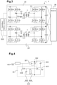
figure 2 est un dispositif de conversion continu-continu selon un premier mode de réalisation de l'invention ; - la
figure 3 est un dispositif de conversion continu-continu selon un deuxième mode de réalisation de l'invention ; et - la
figure 4 est une vue de détail d'une structure d'un redresseur d'un convertisseur selon le premier ou deuxième mode de réalisation de l'invention. - En référence à la
figure 2 , dans un premier mode de réalisation de l'invention, un chargeur non représenté dans son ensemble, comprend un étage redresseur correcteur du facteur de puissance dit PFC, et un dispositif de conversion continu-continu 1 comprenant un convertisseur LLC résonant à pont complet 20 bidirectionnel. - Le convertisseur LLC résonant à pont complet 20 comprend un pont complet de commutation 21 générant un signal ou courant carré excitant un circuit LLC 22, composé d'un condensateur et de deux inductances. Le circuit LLC 22 produit alors un courant sinusoïdal résonant transmis par un transformateur 23 et redressé par un pont redresseur 24. Le signal/courant redressé et amplifié est alors filtré par le condensateur de sortie 25 avant d'être collecté par la batterie 26.
- L'ensemble formé par le pont complet de commutation 21 et le circuit LLC 22 est dit circuit primaire ou partie primaire du convertisseur, et l'ensemble formé du redresseur 24 et du condensateur de sortie 25 est dit circuit secondaire, ou partie secondaire du convertisseur.
- Dans le fonctionnement bidirectionnel du chargeur, lorsque le courant est envoyé depuis le primaire vers le secondaire du convertisseur 20, on parle de sens direct de fonctionnement du convertisseur 20, ce qui permet de recharger la batterie 26 depuis un réseau électrique externe connecté au primaire. Le chargeur est en outre conformé pour fonctionner en sens indirect, dans lequel l'énergie accumulée par la batterie 26 transite du secondaire vers le primaire du convertisseur 20 afin d'alimenter le réseau électrique externe.
- Le pont de commutation 21 comprend 4 bras de commutation, chacun étant formé d'une structure 210, 210′, 210ʺ, 210‴, la structure comprend des composants électroniques montés en parallèles les uns des autres.
- Chaque structure 210, 210′, 210ʺ, 210‴ comprenant une diode, un transistor et un condensateur.
- Les structures 210, 210′, 210ʺ, 210‴ sont montées en pont complet, selon une configuration bien connue de l'homme du métier.
- Le circuit LLC 22 et le transformateur 23 sont conformes à ceux de l'art antérieur cité précédemment.
- Le redresseur 24, du circuit secondaire, comprend un pont complet formé de 4 bras de commutation.
- Chaque bras de commutation étant formé d'une structure 240, 240′, 240ʺ, 240‴, la structure comprend des composants électroniques montés en parallèles les uns des autres.
- Chaque structure 240, 240′, 240ʺ, 240‴ comprenant, en référence à la
figure 4 , une diode 302, un transistor 301 et un condensateur 303, selon un montage en pont complet de redresseur. - Le condensateur 303 au circuit secondaire permet de ralentir la montée en tension et permet une coupure du courant sans perte et avec une faible surtension.
- En effet, la structure du convertisseur 20 n'étant pas symétrique, le courant haché au secondaire est plus élevé qu'au primaire lorsque le convertisseur fonctionne dans le sens indirect (sens de décharge).
- Or, ce condensateur 303 au secondaire a pour effet d'affecter négativement le rendement du convertisseur DC-DC 20 lors de son fonctionnement en sens direct.
- Afin de corriger cet inconvénient, chaque structure 240, 240′, 240ʺ, 240‴ du redresseur 24 comprend en outre un montage de coupure 40, permettant de couper l'effet du condensateur (encore appelé snubber) 303 de chaque structure 240, 240′, 240ʺ, 240‴ du redresseur 24 au secondaire lors du fonctionnement du convertisseur 20 en sens direct.
- Ce montage de coupure 40, associé à une structure 240, 240′, 240ʺ, 240‴, en référence à la
figure 4 , comprend un transistor 401, auquel on se réfère comme étant l'autre transistor 401 ou le transistor de coupure 401, par opposition au transistor 301 de la structure associée 240, 240′, 240ʺ, 240‴, monté en série avec le condensateur de la structure 240, 240′, 240ʺ, 240‴, entre le condensateur de la structure 240, 240′, 240ʺ, 240‴ associée et l'anode de la diode de la structure 240, 240′, 240ʺ, 240‴. - Le montage de coupure 40 comprend aussi un montage RC 405 comprenant en parallèle une résistance 404 et un autre condensateur 403, ledit montage RC 405 étant monté entre la grille de l'autre transistor 401 et l'anode de la diode 302 de la structure associée240, 240′, 240ʺ, 240‴.
- Le montage de coupure 40 comprend aussi une diode 406 connectée par sa cathode à la grille de l'autre transistor 401 et par son anode à la grille du transistor 301 de la structure associée 240, 240′, 240ʺ, 240‴.
- Le transistor 401 utilisé pour couper le courant est de très petit calibre par rapport au transistor 301 de la structure. Par exemple le transistor de coupure 401 présente une impédance de 10 ohms alors que le transistor 301 de la structure est de 10 000 ohms, soit mille fois plus gros.
- La commande de coupure et d'enclenchement du montage de coupure 40 est ainsi autogénérée.
- L'avantage est d'augmenter le rendement du convertisseur bidirectionnel et de diminuer les surtensions pour un coût relativement faible.
- Selon un deuxième mode de réalisation de l'invention, en référence à la
figure 3 , le chargeur bidirectionnel comprend un étage de conversion continu-continu 1', comprenant deux convertisseurs DC-DC 20, 20', tel que décrit dans le premier mode de réalisation, montés en parallèles, et contrôlés par une carte micro-électronique 500 - Une telle structure de mise en parallèle des convertisseurs DC-DC 20, 20' permet de supporter des courant élevés, avec une robustesse relativement importante.
- L'invention n'est pas limitée à seulement deux convertisseurs DC-DC montés en parallèles, mais peut comprendre un plus grand nombre de convertisseurs montés en parallèles.
Claims (3)
- Dispositif de conversion continu-continu (1, 1') pour un chargeur de batterie (26) d'accumulateurs électriques, configuré pour être connecté à un réseau électrique externe, apte à fonctionner de manière bidirectionnelle, en recharge de la batterie (26) dans un sens direct et en décharge de la batterie (26) vers le réseau électrique dans un sens indirect, comprenant au moins un convertisseur LLC résonant à pont complet (20),chaque convertisseur LLC résonant à pont complet (20) comprenant :- un pont complet de commutation (21) générant un signal carré, ledit pont complet de commutation (21) comprenant un montage en pont complet de quatre structures (210, 210′, 210ʺ, 210‴), formées chacune d'un transistor (301, 401), d'une diode et d'un condensateur montés en parallèle;- un circuit LLC (22), comprenant un condensateur et deux inductances, excité par ledit signal carré ;- un transformateur (23) transmettant ledit signal issu du circuit LLC (22);- un redresseur (24) redressant le signal transmis par le transformateur (23), ledit redresseur (24) étant formé d'un pont complet de quatre structures (240, 240′, 240ʺ, 240‴), formées chacune d'un transistor (301), d'une diode (302) et d'un condensateur (303) montés en parallèle;- un condensateur de sortie (25) filtrant le signal redressé ;caractérisé en ce que chaque structure (240, 240′, 240ʺ, 240‴) du redresseur (24) comprend en outre un dispositif d'annulation (40) de l'effet du condensateur (303) de la structure (240, 240′, 240ʺ, 240‴) associée, annulant l'effet dudit condensateur (303) lorsque le dispositif de conversion continu-continu (1) fonctionne en mode direct.
- Dispositif de conversion continu-continu (1, 1') selon la revendication 1, caractérisé en ce que ledit dispositif d'annulation (40) comprend :- un autre transistor (401) en série avec le condensateur (303) de la structure (240, 240′, 240ʺ, 240‴) associée, entre le condensateur (303) de la structure associée (240, 240′, 240ʺ, 240‴) et l'anode de la diode (302) de la structure associée (240, 240′, 240ʺ, 240‴);- un montage RC (405) comprenant en parallèle une résistance (404) et un autre condensateur (403), ledit montage RC (405) étant monté entre la grille de l'autre transistor (401) et l'anode de la diode (302) de la structure associée (240, 240′, 240ʺ, 240‴); et- une diode (406) connectée par sa cathode à la grille de l'autre transistor (401) et par son anode à la grille du transistor (301) de la structure associée (240, 240′, 240ʺ, 240‴).
- Dispositif de conversion continu-continu (1′) selon la revendication 1 ou 2, caractérisé en ce qu'il comprend deux convertisseurs LLC résonants à pont complet (20, 20′) en parallèle.
Applications Claiming Priority (2)
| Application Number | Priority Date | Filing Date | Title |
|---|---|---|---|
| FR1762827A FR3076123B1 (fr) | 2017-12-21 | 2017-12-21 | Convertisseur dc-dc pour chargeur bidirectionnel. |
| PCT/EP2018/085144 WO2019121477A1 (fr) | 2017-12-21 | 2018-12-17 | Convertisseur dc-dc pour chargeur bidirectionnel |
Publications (2)
| Publication Number | Publication Date |
|---|---|
| EP3729627A1 EP3729627A1 (fr) | 2020-10-28 |
| EP3729627B1 true EP3729627B1 (fr) | 2022-02-02 |
Family
ID=61913306
Family Applications (1)
| Application Number | Title | Priority Date | Filing Date |
|---|---|---|---|
| EP18815747.3A Active EP3729627B1 (fr) | 2017-12-21 | 2018-12-17 | Convertisseur dc-dc pour chargeur bidirectionnel |
Country Status (4)
| Country | Link |
|---|---|
| EP (1) | EP3729627B1 (fr) |
| JP (1) | JP6923087B2 (fr) |
| FR (1) | FR3076123B1 (fr) |
| WO (1) | WO2019121477A1 (fr) |
Families Citing this family (4)
| Publication number | Priority date | Publication date | Assignee | Title |
|---|---|---|---|---|
| US11050354B2 (en) * | 2019-09-27 | 2021-06-29 | Infineon Technologies Austria Ag | Bi-directional LLC converter |
| US20210379393A1 (en) * | 2020-05-26 | 2021-12-09 | Zoll Medical Corporation | Electrotherapeutic waveform and pulse generation and delivery system and method |
| US11621579B2 (en) | 2021-06-15 | 2023-04-04 | Schneider Electric It Corporation | Line-interactive uninterruptible power supply with integrated charger |
| US11777338B2 (en) | 2021-06-15 | 2023-10-03 | Schneider Electric It Corporation | AC switch PFC with integrated charger and DC-DC for online UPS systems |
Family Cites Families (9)
| Publication number | Priority date | Publication date | Assignee | Title |
|---|---|---|---|---|
| JP4527616B2 (ja) * | 2005-06-24 | 2010-08-18 | 株式会社日立製作所 | 絶縁共振形双方向dc/dcコンバータ及びその制御方法 |
| US9509223B2 (en) * | 2011-12-21 | 2016-11-29 | Eaton Industries Company | LLC bidirectional resonant converter and methods of controlling |
| JP5941826B2 (ja) * | 2012-11-06 | 2016-06-29 | 日鉄住金テックスエンジ株式会社 | 二次電池用双方向電源装置及びその制御方法 |
| FR3001843B1 (fr) * | 2013-02-04 | 2015-03-13 | Renault Sa | Dispositif et procede correspondant de gestion de batteries de vehicule automobile, en particulier une batterie basse tension et une batterie haute tension |
| JP2014217196A (ja) * | 2013-04-26 | 2014-11-17 | パナソニック株式会社 | 双方向dc/dcコンバータ |
| EP3123592B1 (fr) * | 2014-03-27 | 2019-08-21 | Schneider Electric IT Corporation | Convertisseur continu-continu bidirectionnel |
| JP6406031B2 (ja) * | 2015-01-26 | 2018-10-17 | 株式会社デンソー | Dcdcコンバータ |
| EP3358733A4 (fr) * | 2015-12-04 | 2019-04-17 | Murata Manufacturing Co., Ltd. | Dispositif de conversion de puissance |
| GB201602044D0 (en) * | 2016-02-04 | 2016-03-23 | Eltek As | Bidirectional DC-DC resonant converter |
-
2017
- 2017-12-21 FR FR1762827A patent/FR3076123B1/fr not_active Expired - Fee Related
-
2018
- 2018-12-17 JP JP2020532676A patent/JP6923087B2/ja not_active Expired - Fee Related
- 2018-12-17 EP EP18815747.3A patent/EP3729627B1/fr active Active
- 2018-12-17 WO PCT/EP2018/085144 patent/WO2019121477A1/fr not_active Ceased
Also Published As
| Publication number | Publication date |
|---|---|
| FR3076123A1 (fr) | 2019-06-28 |
| JP6923087B2 (ja) | 2021-08-18 |
| FR3076123B1 (fr) | 2021-01-08 |
| WO2019121477A1 (fr) | 2019-06-27 |
| EP3729627A1 (fr) | 2020-10-28 |
| JP2021506220A (ja) | 2021-02-18 |
Similar Documents
| Publication | Publication Date | Title |
|---|---|---|
| US7126053B2 (en) | Power generation system and power generation apparatus | |
| US9509174B2 (en) | Device for improving endurance of terminal and terminal thereof | |
| EP3607644B1 (fr) | Procede de commande d'un dispositif de charge embarque sur un vehicule electrique ou hybride | |
| WO2019121477A1 (fr) | Convertisseur dc-dc pour chargeur bidirectionnel | |
| EP3568905A1 (fr) | Chargeur de batterie d'accumulateurs électriques bidirectionnel | |
| FR2963508A1 (fr) | Convertisseur dc/dc quadratique double boost bidirectionnel en courant | |
| JP2010541251A (ja) | 太陽光発電電荷軽減デバイス、システムおよび方法 | |
| EP3161951A1 (fr) | Convertisseur de tension comprenant un circuit convertisseur dc/dc isole | |
| CN105490530A (zh) | 一种采用开关电感和电压举升技术的准z源变换器 | |
| CN105490523A (zh) | 一种开关准z源型升压变换器 | |
| CN103944399A (zh) | 低输入电流纹波单开关高增益变换器 | |
| CN108736707B (zh) | 一种具有开关电感结构的boost变换器 | |
| CN105490538A (zh) | 一种改进的开关电感型准z源变换器 | |
| EP3161950A1 (fr) | Convertisseur de tension comprenant un circuit convertisseur dc/dc isole | |
| CN105529918A (zh) | 一种高增益Trans-Z源升压变换器 | |
| FR3027470A1 (fr) | Convertisseur dc/dc isole et procede de conversion de tension | |
| EP2550728B1 (fr) | Convertisseur alternatif/continu a isolement galvanique | |
| CN115940793A (zh) | 一种光伏发电系统和光伏系统 | |
| CN208675110U (zh) | 光伏功率优化器 | |
| EP3276810B1 (fr) | Convertisseur dc-dc isolé et batterie électrique comprenant un convertisseur dc-dc isolé | |
| FR3078212A1 (fr) | Convertisseur dc-dc pour chargeur bidirectionnel. | |
| CN119765911A (zh) | 一种用于氢燃料电池并网系统的低电应力高增益直流升压变换器、变换器控制方法及装置 | |
| KR101276585B1 (ko) | 전자 릴레이 인핸서 및 전자 릴레이 인핸서를 구비한 태양전지 시스템 | |
| KR101276586B1 (ko) | 전자소자 및 전자소자를 포함하는 전자 릴레이 인핸서 | |
| FR3044182A1 (fr) | Convertisseur continu-continu et architecture electrique associee |
Legal Events
| Date | Code | Title | Description |
|---|---|---|---|
| STAA | Information on the status of an ep patent application or granted ep patent |
Free format text: STATUS: UNKNOWN |
|
| STAA | Information on the status of an ep patent application or granted ep patent |
Free format text: STATUS: THE INTERNATIONAL PUBLICATION HAS BEEN MADE |
|
| PUAI | Public reference made under article 153(3) epc to a published international application that has entered the european phase |
Free format text: ORIGINAL CODE: 0009012 |
|
| STAA | Information on the status of an ep patent application or granted ep patent |
Free format text: STATUS: REQUEST FOR EXAMINATION WAS MADE |
|
| 17P | Request for examination filed |
Effective date: 20200410 |
|
| AK | Designated contracting states |
Kind code of ref document: A1 Designated state(s): AL AT BE BG CH CY CZ DE DK EE ES FI FR GB GR HR HU IE IS IT LI LT LU LV MC MK MT NL NO PL PT RO RS SE SI SK SM TR |
|
| AX | Request for extension of the european patent |
Extension state: BA ME |
|
| DAV | Request for validation of the european patent (deleted) | ||
| DAX | Request for extension of the european patent (deleted) | ||
| GRAP | Despatch of communication of intention to grant a patent |
Free format text: ORIGINAL CODE: EPIDOSNIGR1 |
|
| STAA | Information on the status of an ep patent application or granted ep patent |
Free format text: STATUS: GRANT OF PATENT IS INTENDED |
|
| INTG | Intention to grant announced |
Effective date: 20210913 |
|
| GRAS | Grant fee paid |
Free format text: ORIGINAL CODE: EPIDOSNIGR3 |
|
| GRAA | (expected) grant |
Free format text: ORIGINAL CODE: 0009210 |
|
| STAA | Information on the status of an ep patent application or granted ep patent |
Free format text: STATUS: THE PATENT HAS BEEN GRANTED |
|
| AK | Designated contracting states |
Kind code of ref document: B1 Designated state(s): AL AT BE BG CH CY CZ DE DK EE ES FI FR GB GR HR HU IE IS IT LI LT LU LV MC MK MT NL NO PL PT RO RS SE SI SK SM TR |
|
| REG | Reference to a national code |
Ref country code: GB Ref legal event code: FG4D Free format text: NOT ENGLISH |
|
| REG | Reference to a national code |
Ref country code: CH Ref legal event code: EP Ref country code: AT Ref legal event code: REF Ref document number: 1466835 Country of ref document: AT Kind code of ref document: T Effective date: 20220215 |
|
| REG | Reference to a national code |
Ref country code: DE Ref legal event code: R096 Ref document number: 602018030405 Country of ref document: DE |
|
| RAP4 | Party data changed (patent owner data changed or rights of a patent transferred) |
Owner name: NISSAN MOTOR CO., LTD. Owner name: RENAULT S.A.S |
|
| REG | Reference to a national code |
Ref country code: IE Ref legal event code: FG4D Free format text: LANGUAGE OF EP DOCUMENT: FRENCH |
|
| REG | Reference to a national code |
Ref country code: LT Ref legal event code: MG9D |
|
| REG | Reference to a national code |
Ref country code: NL Ref legal event code: MP Effective date: 20220202 |
|
| REG | Reference to a national code |
Ref country code: AT Ref legal event code: MK05 Ref document number: 1466835 Country of ref document: AT Kind code of ref document: T Effective date: 20220202 |
|
| RAP4 | Party data changed (patent owner data changed or rights of a patent transferred) |
Owner name: NISSAN MOTOR CO., LTD. Owner name: RENAULT S.A.S |
|
| PG25 | Lapsed in a contracting state [announced via postgrant information from national office to epo] |
Ref country code: SE Free format text: LAPSE BECAUSE OF FAILURE TO SUBMIT A TRANSLATION OF THE DESCRIPTION OR TO PAY THE FEE WITHIN THE PRESCRIBED TIME-LIMIT Effective date: 20220202 Ref country code: RS Free format text: LAPSE BECAUSE OF FAILURE TO SUBMIT A TRANSLATION OF THE DESCRIPTION OR TO PAY THE FEE WITHIN THE PRESCRIBED TIME-LIMIT Effective date: 20220202 Ref country code: PT Free format text: LAPSE BECAUSE OF FAILURE TO SUBMIT A TRANSLATION OF THE DESCRIPTION OR TO PAY THE FEE WITHIN THE PRESCRIBED TIME-LIMIT Effective date: 20220602 Ref country code: NO Free format text: LAPSE BECAUSE OF FAILURE TO SUBMIT A TRANSLATION OF THE DESCRIPTION OR TO PAY THE FEE WITHIN THE PRESCRIBED TIME-LIMIT Effective date: 20220502 Ref country code: NL Free format text: LAPSE BECAUSE OF FAILURE TO SUBMIT A TRANSLATION OF THE DESCRIPTION OR TO PAY THE FEE WITHIN THE PRESCRIBED TIME-LIMIT Effective date: 20220202 Ref country code: LT Free format text: LAPSE BECAUSE OF FAILURE TO SUBMIT A TRANSLATION OF THE DESCRIPTION OR TO PAY THE FEE WITHIN THE PRESCRIBED TIME-LIMIT Effective date: 20220202 Ref country code: HR Free format text: LAPSE BECAUSE OF FAILURE TO SUBMIT A TRANSLATION OF THE DESCRIPTION OR TO PAY THE FEE WITHIN THE PRESCRIBED TIME-LIMIT Effective date: 20220202 Ref country code: ES Free format text: LAPSE BECAUSE OF FAILURE TO SUBMIT A TRANSLATION OF THE DESCRIPTION OR TO PAY THE FEE WITHIN THE PRESCRIBED TIME-LIMIT Effective date: 20220202 Ref country code: BG Free format text: LAPSE BECAUSE OF FAILURE TO SUBMIT A TRANSLATION OF THE DESCRIPTION OR TO PAY THE FEE WITHIN THE PRESCRIBED TIME-LIMIT Effective date: 20220502 |
|
| PG25 | Lapsed in a contracting state [announced via postgrant information from national office to epo] |
Ref country code: PL Free format text: LAPSE BECAUSE OF FAILURE TO SUBMIT A TRANSLATION OF THE DESCRIPTION OR TO PAY THE FEE WITHIN THE PRESCRIBED TIME-LIMIT Effective date: 20220202 Ref country code: LV Free format text: LAPSE BECAUSE OF FAILURE TO SUBMIT A TRANSLATION OF THE DESCRIPTION OR TO PAY THE FEE WITHIN THE PRESCRIBED TIME-LIMIT Effective date: 20220202 Ref country code: GR Free format text: LAPSE BECAUSE OF FAILURE TO SUBMIT A TRANSLATION OF THE DESCRIPTION OR TO PAY THE FEE WITHIN THE PRESCRIBED TIME-LIMIT Effective date: 20220503 Ref country code: FI Free format text: LAPSE BECAUSE OF FAILURE TO SUBMIT A TRANSLATION OF THE DESCRIPTION OR TO PAY THE FEE WITHIN THE PRESCRIBED TIME-LIMIT Effective date: 20220202 Ref country code: AT Free format text: LAPSE BECAUSE OF FAILURE TO SUBMIT A TRANSLATION OF THE DESCRIPTION OR TO PAY THE FEE WITHIN THE PRESCRIBED TIME-LIMIT Effective date: 20220202 |
|
| PG25 | Lapsed in a contracting state [announced via postgrant information from national office to epo] |
Ref country code: IS Free format text: LAPSE BECAUSE OF FAILURE TO SUBMIT A TRANSLATION OF THE DESCRIPTION OR TO PAY THE FEE WITHIN THE PRESCRIBED TIME-LIMIT Effective date: 20220602 |
|
| PG25 | Lapsed in a contracting state [announced via postgrant information from national office to epo] |
Ref country code: SM Free format text: LAPSE BECAUSE OF FAILURE TO SUBMIT A TRANSLATION OF THE DESCRIPTION OR TO PAY THE FEE WITHIN THE PRESCRIBED TIME-LIMIT Effective date: 20220202 Ref country code: SK Free format text: LAPSE BECAUSE OF FAILURE TO SUBMIT A TRANSLATION OF THE DESCRIPTION OR TO PAY THE FEE WITHIN THE PRESCRIBED TIME-LIMIT Effective date: 20220202 Ref country code: RO Free format text: LAPSE BECAUSE OF FAILURE TO SUBMIT A TRANSLATION OF THE DESCRIPTION OR TO PAY THE FEE WITHIN THE PRESCRIBED TIME-LIMIT Effective date: 20220202 Ref country code: EE Free format text: LAPSE BECAUSE OF FAILURE TO SUBMIT A TRANSLATION OF THE DESCRIPTION OR TO PAY THE FEE WITHIN THE PRESCRIBED TIME-LIMIT Effective date: 20220202 Ref country code: DK Free format text: LAPSE BECAUSE OF FAILURE TO SUBMIT A TRANSLATION OF THE DESCRIPTION OR TO PAY THE FEE WITHIN THE PRESCRIBED TIME-LIMIT Effective date: 20220202 Ref country code: CZ Free format text: LAPSE BECAUSE OF FAILURE TO SUBMIT A TRANSLATION OF THE DESCRIPTION OR TO PAY THE FEE WITHIN THE PRESCRIBED TIME-LIMIT Effective date: 20220202 |
|
| REG | Reference to a national code |
Ref country code: DE Ref legal event code: R097 Ref document number: 602018030405 Country of ref document: DE |
|
| PG25 | Lapsed in a contracting state [announced via postgrant information from national office to epo] |
Ref country code: AL Free format text: LAPSE BECAUSE OF FAILURE TO SUBMIT A TRANSLATION OF THE DESCRIPTION OR TO PAY THE FEE WITHIN THE PRESCRIBED TIME-LIMIT Effective date: 20220202 |
|
| PLBE | No opposition filed within time limit |
Free format text: ORIGINAL CODE: 0009261 |
|
| STAA | Information on the status of an ep patent application or granted ep patent |
Free format text: STATUS: NO OPPOSITION FILED WITHIN TIME LIMIT |
|
| 26N | No opposition filed |
Effective date: 20221103 |
|
| PG25 | Lapsed in a contracting state [announced via postgrant information from national office to epo] |
Ref country code: SI Free format text: LAPSE BECAUSE OF FAILURE TO SUBMIT A TRANSLATION OF THE DESCRIPTION OR TO PAY THE FEE WITHIN THE PRESCRIBED TIME-LIMIT Effective date: 20220202 |
|
| PG25 | Lapsed in a contracting state [announced via postgrant information from national office to epo] |
Ref country code: IT Free format text: LAPSE BECAUSE OF FAILURE TO SUBMIT A TRANSLATION OF THE DESCRIPTION OR TO PAY THE FEE WITHIN THE PRESCRIBED TIME-LIMIT Effective date: 20220202 |
|
| REG | Reference to a national code |
Ref country code: CH Ref legal event code: PL |
|
| REG | Reference to a national code |
Ref country code: BE Ref legal event code: MM Effective date: 20221231 |
|
| PG25 | Lapsed in a contracting state [announced via postgrant information from national office to epo] |
Ref country code: LU Free format text: LAPSE BECAUSE OF NON-PAYMENT OF DUE FEES Effective date: 20221217 |
|
| PG25 | Lapsed in a contracting state [announced via postgrant information from national office to epo] |
Ref country code: LI Free format text: LAPSE BECAUSE OF NON-PAYMENT OF DUE FEES Effective date: 20221231 Ref country code: IE Free format text: LAPSE BECAUSE OF NON-PAYMENT OF DUE FEES Effective date: 20221217 Ref country code: CH Free format text: LAPSE BECAUSE OF NON-PAYMENT OF DUE FEES Effective date: 20221231 |
|
| PG25 | Lapsed in a contracting state [announced via postgrant information from national office to epo] |
Ref country code: BE Free format text: LAPSE BECAUSE OF NON-PAYMENT OF DUE FEES Effective date: 20221231 |
|
| PG25 | Lapsed in a contracting state [announced via postgrant information from national office to epo] |
Ref country code: CY Free format text: LAPSE BECAUSE OF FAILURE TO SUBMIT A TRANSLATION OF THE DESCRIPTION OR TO PAY THE FEE WITHIN THE PRESCRIBED TIME-LIMIT Effective date: 20220202 |
|
| PG25 | Lapsed in a contracting state [announced via postgrant information from national office to epo] |
Ref country code: MK Free format text: LAPSE BECAUSE OF FAILURE TO SUBMIT A TRANSLATION OF THE DESCRIPTION OR TO PAY THE FEE WITHIN THE PRESCRIBED TIME-LIMIT Effective date: 20220202 Ref country code: HU Free format text: LAPSE BECAUSE OF FAILURE TO SUBMIT A TRANSLATION OF THE DESCRIPTION OR TO PAY THE FEE WITHIN THE PRESCRIBED TIME-LIMIT; INVALID AB INITIO Effective date: 20181217 |
|
| PG25 | Lapsed in a contracting state [announced via postgrant information from national office to epo] |
Ref country code: MC Free format text: LAPSE BECAUSE OF FAILURE TO SUBMIT A TRANSLATION OF THE DESCRIPTION OR TO PAY THE FEE WITHIN THE PRESCRIBED TIME-LIMIT Effective date: 20220202 |
|
| PG25 | Lapsed in a contracting state [announced via postgrant information from national office to epo] |
Ref country code: TR Free format text: LAPSE BECAUSE OF FAILURE TO SUBMIT A TRANSLATION OF THE DESCRIPTION OR TO PAY THE FEE WITHIN THE PRESCRIBED TIME-LIMIT Effective date: 20220202 Ref country code: MC Free format text: LAPSE BECAUSE OF FAILURE TO SUBMIT A TRANSLATION OF THE DESCRIPTION OR TO PAY THE FEE WITHIN THE PRESCRIBED TIME-LIMIT Effective date: 20220202 |
|
| REG | Reference to a national code |
Ref country code: DE Ref legal event code: R081 Ref document number: 602018030405 Country of ref document: DE Owner name: NISSAN MOTOR CO., LTD., YOKOHAMA-SHI, JP Free format text: FORMER OWNERS: NISSAN MOTOR CO., LTD., YOKOHAMA-SHI, KANAGAWA-KEN, JP; RENAULT S.A.S., BOULOGNE-BILLANCOURT, FR Ref country code: DE Ref legal event code: R081 Ref document number: 602018030405 Country of ref document: DE Owner name: AMPERE S.A.S., FR Free format text: FORMER OWNERS: NISSAN MOTOR CO., LTD., YOKOHAMA-SHI, KANAGAWA-KEN, JP; RENAULT S.A.S., BOULOGNE-BILLANCOURT, FR |
|
| PG25 | Lapsed in a contracting state [announced via postgrant information from national office to epo] |
Ref country code: MT Free format text: LAPSE BECAUSE OF FAILURE TO SUBMIT A TRANSLATION OF THE DESCRIPTION OR TO PAY THE FEE WITHIN THE PRESCRIBED TIME-LIMIT Effective date: 20220202 |
|
| REG | Reference to a national code |
Ref country code: GB Ref legal event code: 732E Free format text: REGISTERED BETWEEN 20250501 AND 20250507 |
|
| PGFP | Annual fee paid to national office [announced via postgrant information from national office to epo] |
Ref country code: DE Payment date: 20251211 Year of fee payment: 8 |
|
| PGFP | Annual fee paid to national office [announced via postgrant information from national office to epo] |
Ref country code: GB Payment date: 20251219 Year of fee payment: 8 |
|
| PGFP | Annual fee paid to national office [announced via postgrant information from national office to epo] |
Ref country code: FR Payment date: 20251229 Year of fee payment: 8 |