EP3729430B1 - System und verfahren für remote-support - Google Patents
System und verfahren für remote-support Download PDFInfo
- Publication number
- EP3729430B1 EP3729430B1 EP18830473.7A EP18830473A EP3729430B1 EP 3729430 B1 EP3729430 B1 EP 3729430B1 EP 18830473 A EP18830473 A EP 18830473A EP 3729430 B1 EP3729430 B1 EP 3729430B1
- Authority
- EP
- European Patent Office
- Prior art keywords
- video
- terminal unit
- graphic
- module
- phase
- Prior art date
- Legal status (The legal status is an assumption and is not a legal conclusion. Google has not performed a legal analysis and makes no representation as to the accuracy of the status listed.)
- Active
Links
Images



Classifications
-
- G—PHYSICS
- G11—INFORMATION STORAGE
- G11B—INFORMATION STORAGE BASED ON RELATIVE MOVEMENT BETWEEN RECORD CARRIER AND TRANSDUCER
- G11B27/00—Editing; Indexing; Addressing; Timing or synchronising; Monitoring; Measuring tape travel
- G11B27/02—Editing, e.g. varying the order of information signals recorded on, or reproduced from, record carriers
- G11B27/031—Electronic editing of digitised analogue information signals, e.g. audio or video signals
-
- H—ELECTRICITY
- H04—ELECTRIC COMMUNICATION TECHNIQUE
- H04N—PICTORIAL COMMUNICATION, e.g. TELEVISION
- H04N5/00—Details of television systems
- H04N5/04—Synchronising
-
- G—PHYSICS
- G06—COMPUTING OR CALCULATING; COUNTING
- G06T—IMAGE DATA PROCESSING OR GENERATION, IN GENERAL
- G06T11/00—Two-dimensional [2D] image generation
-
- G—PHYSICS
- G11—INFORMATION STORAGE
- G11B—INFORMATION STORAGE BASED ON RELATIVE MOVEMENT BETWEEN RECORD CARRIER AND TRANSDUCER
- G11B27/00—Editing; Indexing; Addressing; Timing or synchronising; Monitoring; Measuring tape travel
- G11B27/02—Editing, e.g. varying the order of information signals recorded on, or reproduced from, record carriers
- G11B27/031—Electronic editing of digitised analogue information signals, e.g. audio or video signals
- G11B27/036—Insert-editing
-
- G—PHYSICS
- G11—INFORMATION STORAGE
- G11B—INFORMATION STORAGE BASED ON RELATIVE MOVEMENT BETWEEN RECORD CARRIER AND TRANSDUCER
- G11B27/00—Editing; Indexing; Addressing; Timing or synchronising; Monitoring; Measuring tape travel
- G11B27/10—Indexing; Addressing; Timing or synchronising; Measuring tape travel
-
- G—PHYSICS
- G11—INFORMATION STORAGE
- G11B—INFORMATION STORAGE BASED ON RELATIVE MOVEMENT BETWEEN RECORD CARRIER AND TRANSDUCER
- G11B27/00—Editing; Indexing; Addressing; Timing or synchronising; Monitoring; Measuring tape travel
- G11B27/10—Indexing; Addressing; Timing or synchronising; Measuring tape travel
- G11B27/11—Indexing; Addressing; Timing or synchronising; Measuring tape travel by using information not detectable on the record carrier
-
- G—PHYSICS
- G11—INFORMATION STORAGE
- G11B—INFORMATION STORAGE BASED ON RELATIVE MOVEMENT BETWEEN RECORD CARRIER AND TRANSDUCER
- G11B27/00—Editing; Indexing; Addressing; Timing or synchronising; Monitoring; Measuring tape travel
- G11B27/10—Indexing; Addressing; Timing or synchronising; Measuring tape travel
- G11B27/34—Indicating arrangements
-
- H—ELECTRICITY
- H04—ELECTRIC COMMUNICATION TECHNIQUE
- H04N—PICTORIAL COMMUNICATION, e.g. TELEVISION
- H04N21/00—Selective content distribution, e.g. interactive television or video on demand [VOD]
- H04N21/40—Client devices specifically adapted for the reception of or interaction with content, e.g. set-top-box [STB]; Operations thereof
- H04N21/43—Processing of content or additional data, e.g. demultiplexing additional data from a digital video stream; Elementary client operations, e.g. monitoring of home network or synchronising decoder's clock; Client middleware
- H04N21/4302—Content synchronisation processes, e.g. decoder synchronisation
- H04N21/4307—Synchronising the rendering of multiple content streams or additional data on devices, e.g. synchronisation of audio on a mobile phone with the video output on the TV screen
- H04N21/43074—Synchronising the rendering of multiple content streams or additional data on devices, e.g. synchronisation of audio on a mobile phone with the video output on the TV screen of additional data with content streams on the same device, e.g. of EPG data or interactive icon with a TV programme
-
- H—ELECTRICITY
- H04—ELECTRIC COMMUNICATION TECHNIQUE
- H04N—PICTORIAL COMMUNICATION, e.g. TELEVISION
- H04N5/00—Details of television systems
- H04N5/222—Studio circuitry; Studio devices; Studio equipment
-
- H—ELECTRICITY
- H04—ELECTRIC COMMUNICATION TECHNIQUE
- H04N—PICTORIAL COMMUNICATION, e.g. TELEVISION
- H04N5/00—Details of television systems
- H04N5/222—Studio circuitry; Studio devices; Studio equipment
- H04N5/262—Studio circuits, e.g. for mixing, switching-over, change of character of image, other special effects ; Cameras specially adapted for the electronic generation of special effects
- H04N5/272—Means for inserting a foreground image in a background image, i.e. inlay, outlay
-
- H—ELECTRICITY
- H04—ELECTRIC COMMUNICATION TECHNIQUE
- H04N—PICTORIAL COMMUNICATION, e.g. TELEVISION
- H04N5/00—Details of television systems
- H04N5/38—Transmitter circuitry for the transmission of television signals according to analogue transmission standards
Definitions
- the present invention relates to the field of telecommunications, particularly to the field of remote support communication, and more particularly to the field of remote support communication exploiting both audio and video communication.
- the present invention relates to a system, a method and terminal units which can be applied to a remote support communication scenario in which a communication is established between two (or more) persons (hereinafter, "actors") comprising at least a user who wants to obtain information about a physical object or apparatus (e.g., instructions about the way of using or operating such object) and a support operator knowing the required information.
- the remote communication should be an audiovisual communication, exploiting both an audio channel and a video channel.
- the support operator is provided with the capability to point at specific portions of the physical object by drawing graphical elements, and the user is provided with the possibility of seeing the portions of the physical object indicated by the support operator by simply watching the video of the object with such graphical elements superimposed thereon.
- a very important issue of this kind of remote communication relates the synchronization between the video displayed by the user and the graphical elements that have to be superimposed thereon.
- the graphical elements are indeed generated at the support operator side at the time instant in which the support operator receives the video depicting the object.
- the operations required to be carried out by the support operator for generating the video with the graphical elements superimposed thereon and the transmission of the latter from the support operator to the user require a non-negligible amount of time.
- the enriched video with the graphical elements superimposed thereon received by the user is thus delayed with respect to when the video is acquired by the user, and therefore also the graphical elements exhibits the same delay with respect to the acquisition time.
- WEBDOVE A web-based collaboration system for physical task
- Weiyi Yang, Jiazhi Ou, Yong Rut, Jie Yang, 2006 IEEE International Conference on Multimedia and Expo, Toronto, Ont., Canada, 9-12 July 2006 discloses the WEBDOVE platform that is web based, and has the purpose to extend the collaboration activity to more actors. All the actors may contribute as support operators, enriching the received video. Each actor receives and sends videos that can be enriched with graphical elements by himself/herself. Each video acquired by an actor is sent to all the other actors through a real time video communication.
- a moderator server is provided, which is configured to propagate the graphical elements to all the actors.
- US 2015/035959 A1 (AMBLE RAVI N [US] ET AL) 5 February 2015 (2015-02-05) discloses a telemedicine system , where an operator at a patient telemedicine device is visualizing a video stream captured by a camera.
- the video stream can be transmitted to a specialist telemedicine device in real time which can provide annotations to the original patient telemedicine device, which are rendered in real time.
- the Applicant has devised a solution for allowing an improved remote support communication between a user and a support operator in which the video displayed by the user is correctly synchronized with the graphical element drawn by the support operator.
- the present invention is directed to a user terminal unit, as defined in appended claim 1, a remote Support Communication System, as defined in appended claim 8, a method as defined in appended claim 10.
- Advantageous aspects are defined in the corresponding dependent claims.
- FIG. 1 illustrates in terms of functional blocks a remote support communication system 100 according to an embodiment of the present invention.
- the remote support communication system 100 is configured to provide remote audio and video communication between two or more actors comprising a user A requiring to obtain information about a physical object or apparatus O and a support operator (or simply "operator") B having such required information.
- the user A and the operator B are remote from each other, being located in different locations, such as in different buildings, while the object O is located in the same location of the user A, or at least very close to the latter.
- the remote support communication system 100 comprises a user terminal unit - referred to as first terminal unit T1 - adapted to be operated by the user A, and an operator terminal unit - referred to as second terminal unit T2 - adapted to be operated by the operator B.
- the first terminal unit T1 comprises an audio communication module 102 adapted to transmit and receive audio signals to/from the second terminal unit T2 over a bidirectional (from T1 to T2 and vice versa) audio communication channel AC.
- the audio communication module 102 further comprises an audio signal generation unit (not illustrated) configured to generate an audio signal from a speech uttered by the user A and captured by means of a microphone (not illustrated), and an audio speaker system (not illustrated).
- the first terminal unit T1 further comprises a camera module 104 adapted to shoot video images of the object O.
- a video processing module 106 is provided, which is configured to process, ( e.g ., performing coding, compressing and buffering operations) the output of the camera module 104 to generate a corresponding video V depicting the object O.
- the first terminal unit T1 further comprises a video transmission module 108 adapted to transmit the video V to the second terminal unit T2 over a unidirectional (from T1 to T2 ) video communication channel VC, such as a 3G, a 4G, a WiFi, an ADSL, a lan communication channel.
- the video V is transmitted with compression techniques such to guarantee a low transmission bandwidth occupation, and at the same time a video quality sufficient to allow an efficient interaction with the shot object O.
- compression techniques such to guarantee a low transmission bandwidth occupation, and at the same time a video quality sufficient to allow an efficient interaction with the shot object O.
- the H.264 video compression standard may be advantageously exploited.
- the video is encoded with a coding technique which is adapted in real time based on the bandwidth available on the video communication channel VC, in such a way to reduce the video reception delay as much as possible.
- the first terminal unit T1 comprises a graphic receiver module 110 configured to receive data about digital graphic elements G - such as arrows, circles, lines - sent by the second terminal unit T2 over a unidirectional (from T2 to T1 ) communication channel GC.
- a graphic receiver module 110 configured to receive data about digital graphic elements G - such as arrows, circles, lines - sent by the second terminal unit T2 over a unidirectional (from T2 to T1 ) communication channel GC.
- the first terminal unit T1 further comprises a display module 112 adapted to display the object's O images shot by the camera module 104.
- the display module 112 is designed to display a video D which may be either the video V as directly generated by video processing module 106 or a processed version of such video with digital graphic elements G superimposed thereon based on the data received from the second terminal unit T2 over the communication channel CG.
- the first terminal unit T1 further comprises a synchronization module 114 configured to carry out a synchronization procedure directed to control the generation and the display of the video D on the display module 112, as will be described in detail in the following of the description.
- the second terminal unit T2 comprises a further audio communication module 140 adapted to transmit and receive audio signals to/from the first terminal unit T1 over the audio communication channel AC.
- the further audio communication module 140 further comprises an audio signal generation unit (not illustrated) configured to generate an audio signal from a speech uttered by the operator B and captured by means of a microphone (not illustrated), and an audio speaker system (not illustrated).
- the second terminal unit T2 further comprises a video receiver module 142 adapted to receive the video V transmitted by the first terminal unit T1 over the video communication channel VC.
- the second terminal unit T2 further comprises a display and drawing module 146 configured to display the received video V and provide a drawing area thereon adapted to allow the operator B to generate digital graphic elements G to be superimposed on the video V.
- the display and drawing module 146 may be a video touch screen. While drawing such digital graphic elements G, the operator B is provided with the possibility of viewing the results of his/her operations through the display and drawing module 146, which is configured to display the video V with the drawn digital graphic elements G superimposed thereon.
- the second terminal unit T2 comprises a graphic transmitter module 150 configured to send data about the digital graphic elements G to the first terminal unit T1 over the communication channel GC.
- the data about the digital graphic elements G are normalized, in such a way that the graphical depiction is invariant with respect to the scale factor and aspect ratio of the drawing area of the display and drawing module 146.
- the first terminal unit T1 associates to each frame f(i) a corresponding timestamp tf(i) which specifies the time instant at which the corresponding frame f(i) has been acquired by the camera module 104.
- each time a new video frame f(i) is acquired by the camera module 104 such video frame f(i) is listed by the synchronization unit 114 in a corresponding list L .
- Each graphic component g(j) represents a graphic element (or a portion thereof) as drawn by the operator B by means of the display and drawing module 146 when he/she was seeing a particular frame f(i) on the display and drawing module 146 itself.
- the second terminal unit T2 associates to each graphic component g(j) a corresponding timestamp tg(j) which is set to the value of the timestamp tf(i) of the frame f(i) of the video V over which the operator B has drawn such graphic component g(j), i.e., the frame f(i) which was displayed on the display and drawing module 146 when the graphic component g(j) was generated ( i.e., drawn). In this way, an association is made between video frames f(i) and graphic components g(j).
- the video D displayed on the display module 112 of the first terminal unit T1 is generated by overlapping the graphic components g(j) on the correct corresponding video frames f(i). According to an embodiment of the present invention, this is guaranteed by means of the synchronization unit 114.
- the solution according to an embodiment of the present invention advantageously provides that the only video transmission is carried out from the first terminal unit T1 to the second terminal unit T2.
- the second terminal unit T2 transmits to the first terminal unit T1 only data about digital graphic elements G, which typically require a far lower amount of data to be transferred compared to a video. In this way the delays introduced by the transmission are significantly reduced.
- the time interval which begins at the acquisition of a new video frame f(i) by the camera module 104 of the first terminal unit T1 and ends at the reception of this video frame f(i) by the second terminal unit T2 is identified as ⁇ T.
- ⁇ T takes into account the video coding, compressing and buffering times, plus the actual transmission time from T1 to T2.
- the time interval which begins at the transmission of a graphic component g(j) by the second terminal unit T2 and ends at the reception of the graphic component g(j) by the first terminal unit T1 is identified as ⁇ G.
- ⁇ T and ⁇ G are approximately constant for each video frame f(i) and for each graphic component g(j).
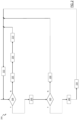
- Figure 2 is a flow chart illustrating the main phases of a synchronization procedure 200 carried out by the synchronization module 114 of the first terminal unit T1 for controlling the generation and the display of the video D on the display module 112 according to an embodiment of the present invention.
- the synchronization procedure 200 is a cyclic procedure, in which the beginning of each procedure cycle is in general triggered with a frequency corresponding to the acquisition frequency af of the frames f(i) of the video V. Therefore, each procedure cycle is in general reiterated with a periodicity corresponding to the inverse of the acquisition frequency af.
- the triggering of a new synchronization procedure 200 cycle may be forced to occur at a different time.
- the first operation of the synchronization procedure 200 provides for checking if there is any new graphic component g(j) received from the second terminal unit T2 (block 204 ).
- the synchronization module 114 accesses the list L of the video frames f(i) previously acquired by the camera module 104 and checks their respective timestamps tf(i) for identifying which is the most recent video frame f(i), i.e., the last one that was acquired (block 205 ). Then, the synchronization module 114 drives the display module 112 to display the identified most recent video frame f(i) (block 206 ) and removes from the list L possible video frames f(i) which are older than said most recent video frame f(i) (block 210 ). At this point, the procedure is stayed for a waiting time ⁇ p corresponding to the inverse of the video frame acquisition frequency af (block 212 ), and then a new procedure cycle is triggered (returning to block 204 ).
- the synchronization module 114 accesses the list L of the video frames f(i) previously acquired by the camera module 104 and checks whether there is a listed video frame f(i) whose time stamp tf(i) is equal to the timestamp tg(j) of said new graphic component g(j) (block 220 ).
- the synchronization module 114 identifies which is the least recent video frame f(i) of the list, and drives the display module 112 to display said identified least recent video frame f(i) (block 230 ). Said identified least recent video frame f(i) is not removed from the list L . It has to be appreciated that the least recent video frame f(i) included in the list L is the video frame f(i) which has been already displayed on the display module 112 in the previous cycle of the procedure. At this point, the procedure is stayed for the waiting time ⁇ p (block 212 ), and then a new procedure cycle is triggered (returning to block 204 ).
- the synchronization module 114 drives the display module 112 to display such video frame f(i) with superimposed thereon the graphic component g(j) (block 240 ).
- the synchronization module 114 then removes from the list L possible video frames f(i) which are older than said video frame f(i) whose time stamp tf(i) is equal to the timestamp tg(j) (block 250 ). At this point, the procedure is stayed for the waiting time ⁇ p (block 212 ), and then a new procedure cycle is triggered (returning to block 204 ).
- the timestamps tg(j) are increased by adding thereto the time at which the corresponding graphic components g(j) have been inserted in the communication channel GC by the second terminal unit T2.
- the difference between the insertion time and the reception time is calculated.
- the various differences are collected for a time window (for example, having a length of 10 seconds). Every time the time window is expired, the time interval ⁇ G is calculated as the average value of such differences.
- the obtained time interval ⁇ G may be used to anticipate the triggering of a new synchronization procedure 200 cycle.
- the synchronization procedure 200 illustrated in Figure 2 may be subdivided in three different main phases, namely a "preview phase” corresponding to the operations following to the exit branch N of block 204, an “alignment phase” corresponding to the operations following to the exit branch Y of block 204 and the exit branch N of block 225, and a “drawing phase” corresponding to the operations following to the exit branch Y of block 204 and the exit branch Y of block 225.
- the alignment phase while graphic components g(j) are now available, such graphic components g(j) corresponds to too old video frames f(i) of the video V acquired by the camera 104, which were already displayed on the display module 112 in a previous time, and have been replaced by subsequent video frames f(i).
- the video D displayed on the display module 112 is formed by the repetition of the last video frame f(i) which was already displayed on the display module 112 in the previous preview phase.
- the available graphic component g(j) is finally temporally aligned to the sequence of video frames f(i) of the video V acquired by the camera module 104.
- the video D displayed on the display module 112 is formed by the video frames f(i) with superimposed thereon the associated ( i.e., having the same timestamps) graphic components g(j).
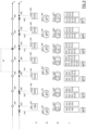
- Figure 3 is a time diagram showing an example of how the video V acquired by the camera module 104, the graphic elements G, the video D displayed on the display module 112 and the list L evolve during six cycles of the synchronization procedure 200.
- the "•" symbols correspond to time instants in which video frames f(i) are acquired by the camera module 104; the " ⁇ " symbols correspond to time instants in which graphic components g(j) are received by the first terminal unit T1, and the "0" symbols correspond to time instants in which a new cycle of the synchronization procedure 200 is triggered (causing the execution of a new reiteration of the check corresponding to block 204 of the procedure).
- the preview phase lasts until the acquisition of the frame f(7).
- the alignment phase when the graphic components g(1) (associated to the frame f(6)) and g(2) (associated to the frame f(7) ) start to arrive at the first terminal unit T1, the video D provides for the repetition of the last frame f(7) displayed in the preview phase.
- the drawing phase starts at the acquisition of the frame f(10), wherein the video frame f(8) is displayed with superimposed thereon the associated graphic component g(3).
- the performance of the remote support communication system 100 may be negatively affected by the drift which can happen between a clock dictating the timing of the operations carried out by the first terminal unit T1 and a clock dictating the timing of the operations carried out by the second terminal unit T2.
- drift adds itself to the transmission times intrinsic to the communication channel CG (i.e., the time interval ⁇ G ).
- the time interval between the reception of two subsequent graphic components g(j), g(j+1) at the first terminal unit T1 is influenced by the drift of the clock dictating the timing with which the frames f(i) are received and displayed at the second terminal unit T2.
- the triggering of a new cycle of the synchronization procedure 200 may be forced to occur at a time which is different than the standard one determined by the waiting time ⁇ p (see block 212 of Figure 2 ).
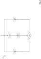
- Figure 4 is a flow chart illustrating the main phases of a forcing procedure 400 carried out by the synchronization module 114 of the first terminal unit T1 in parallel to the synchronization procedure 200 for forcing the triggering of a new cycle of the synchronization procedure 200 when the abovementioned drift has caused an excessive time misalignment between the first terminal unit T1 and the second terminal unit T2.
- the synchronization module 114 calculates (block 410 ) the time interval M occurring between the reception by the first terminal unit T1 of two subsequent graphic components g(j), g(j+1).
- the time interval M may vary in time.
- the next operation provides for calculating the difference ⁇ between such time interval M and the waiting time ⁇ p (block 420 ).
- such waiting time corresponds to the inverse of the frequency af with which the video frames f(i) are acquired by the camera module 104.
- the forcing procedure 400 does not influence the operation of the synchronization procedure 200, and the new cycle thereof is normally triggered after the waiting time ⁇ p is lapsed (see block 212 of Figure 2 ).
- the synchronization module 114 forces the triggering of a new cycle of the synchronization procedure 200, irrespective of the waiting time ⁇ p. In this way, the first terminal unit T1 and the second terminal unit T2 are aligned again in time.
- ⁇ pl2 has been used as a threshold for the difference ⁇ in order to advantageously avoid to cause that the triggering of a new cycle of the synchronization procedure 200 is varied with a too high frequency, avoiding thus to negatively affect the fluidity of the video.
- similar considerations apply in case different threshold values are selected.
- Figures 5 and 6 are time diagrams showing two examples of how the video V acquired by the camera module 140, the graphic elements G, the video D displayed on the display module 112 and the list L evolve in time in case the triggering of a cycle of the synchronization is forced by the forcing procedure 400.
- the video frame acquisition frequency af is equal to 25 Hz
- the waiting time ⁇ p corresponds to 40 msec
- the threshold ⁇ pl2 is equal to 20 milliseconds.
- the synchronization module 114 forces the triggering of a of a new cycle of the synchronization procedure 200 at the reception by the first terminal unit T1 of the graphic component g(5), because the time interval M occurring between the reception by the first terminal unit T1 of the graphic component g(4) and the reception by the first terminal unit T1 of the graphic component g(5) is equal to 65 millesecond, and thus the corresponding absolute value of the difference ⁇ is equal to 25 milliseconds, which is higher than the threshold ⁇ pl2.
- the synchronization module 114 forces the triggering of a of a new cycle of the synchronization procedure 200 at the reception by the first terminal unit T1 of the graphic component g(5), because the time interval M occurring between the reception by the first terminal unit T1 of the graphic component g(4) and the reception by the first terminal unit T1 of the graphic component g(5) is equal to 19 millesecond, and thus the corresponding absolute value of the difference ⁇ is equal to 21 milliseconds, which is higher than the threshold ⁇ pl2.
- 'unit', 'system' or 'module' are herein intended to comprise, but not limited to, hardware, firmware, a combination of hardware and software, software.
- a unit, system or module may be, but is not limited to being, a process running on a processor, a processor, an object, an executable, a thread of execution, a program, and/or a computing device.
- a unit, system or module may comprise an application being executed on a computing device and/or the computing device itself.
- One or more units, systems or modules may be localized on one computing device and/or distributed between two or more computing devices.
- Units, systems or modules may comprise and/or interact with computer readable media having storing data according to various data structures.
- the units, systems or modules may communicate by exploiting local and/or remote processes, preferably by means of electrical, electromagnetic and/or optical signals providing one or more data packets, such as data packets from one unit, system or module interacting with another unit, system or module in a local system, in a distributed system, and/or across a radio network and/or a wired network.
Landscapes
- Engineering & Computer Science (AREA)
- Multimedia (AREA)
- Signal Processing (AREA)
- Physics & Mathematics (AREA)
- General Physics & Mathematics (AREA)
- Theoretical Computer Science (AREA)
- Two-Way Televisions, Distribution Of Moving Picture Or The Like (AREA)
Claims (14)
- Benutzerendgeräteeinheit (T1), wobei die Benutzerendgeräteeinheit (T1) Folgendes umfasst:- ein Kameramodul (104), das dazu ausgelegt ist, Videobilder eines Objekts (O) aufzunehmen, um eine geordnete Sequenz von Videoframes (f(i)) zu erfassen, die ein entsprechendes erstes Video (V) des Objekts (O) bilden;- ein Videoübertragungsmodul (108), das dazu ausgelegt ist, die Videoframes (f(i)) zu einer Bedienerendgeräteeinheit (T2) zu übertragen;- ein graphisches Empfängermodul (110), das dazu ausgelegt ist, digitale grafische Komponenten (g(j)) von der Bedienerendgeräteeinheit (T2) zu empfangen;- ein Anzeigemodul (112), das dazu ausgelegt ist, ein zweites Video (D) auf Basis der Videoframes (f(i)) und auf Basis der empfangenen digitalen grafischen Komponenten (g(j)) anzuzeigen;- ein Synchronisationsmodul (114), das dazu ausgelegt ist, das Anzeigemodul (112) in einer Weise zu steuern, dass empfangene digitale grafische Komponenten (g(j)) angezeigt werden, die jeweilige Videoframes (f(i)) überlagernwobei:- die Benutzerendgeräteeinheit (T1) dazu ausgelegt ist, mit jedem Videoframe (f(i)) einen entsprechenden Framezeitstempel (tf(i)) zu verknüpfen, der die Zeitinstanz spezifiziert, zu der der entsprechende Videoframe (f(i)) vom Kameramodul (104) erfasst wurde;- jede digitale grafische Komponente (g(j)) mit einem jeweiligen grafischen Zeitstempel (tg(j)) verknüpft ist, der wiederum einem jeweiligen Framezeitstempel (tf(i)) entspricht;- das Synchronisationsmodul (114) dazu ausgelegt ist, das Anzeigemodul (112) gemäß einer Synchronisationsprozedur (200) zu steuern, die empfangene digitale grafische Komponenten (g(j)), die auf jeweiligen Videoframes (f(i)) überlagert sind, auf Basis des Framezeitstempels (tf(i)) und auf Basis des grafischen Zeitstempels (tg(j)) anzeigtwobei das Synchronisationsmodul (114) dazu ausgelegt ist, das Anzeigemodul (112) in einer Weise zu steuern, dass während einer ersten Phase der Synchronisationsprozedur (200) das angezeigte zweite Video (D) die Videoframes (f(i)) des ersten Videos (V) als direkt vom Kameramodul (140) erfasst umfasst, wobei die erste Phase einem Zustand entspricht, in dem die Benutzerendgeräteeinheit (T1) keine grafischen Komponenten (g(j)) von der Bedienerendgeräteeinheit (T2) empfängt, dadurch gekennzeichnet, dass:
das Synchronisationsmodul (114) dazu ausgelegt ist, das Anzeigemodul (112) in einer Weise zu steuern, dass während einer zweiten Phase der Synchronisationsprozedur (200), die der ersten Phase folgt, das angezeigte zweite Video (D) die Wiederholung des letzten Videoframes (f(i)) umfasst, das in der ersten Phase angezeigt wurde, wobei die zweite Phase einem Zustand entspricht, in dem die Benutzerendgeräteeinheit (T1) digitale grafische Komponenten (g(j)) empfängt, deren verknüpfte grafische Zeitstempel (tg(j)) gleich Framezeitstempeln (tf(i)) von zuvor angezeigten Videoframes (f(i)) sind, die durch nachfolgende Videoframes (f(i)) ersetzt wurden. - Benutzerendgeräteeinheit (T1) nach Anspruch 1, wobei das Synchronisationsmodul (114) dazu ausgelegt ist, das Anzeigemodul (112) in einer Weise zu steuern, dass während einer dritten Phase der Synchronisationsprozedur (200), die der zweiten Phase folgt, das angezeigte zweite Video (D) Videoframes (f(i)) umfasst, von denen jeder von einer jeweiligen grafischen Komponente (g(j)) überlagert ist, deren grafischer Zeitstempel (tg(j)) gleich dem Framezeitstempel (tf(i)) von jedem Videoframe (f(i)) ist.
- Benutzerendgeräteeinheit (T1) nach Anspruch 2, wobei die Synchronisationsprozedur (200) eine zyklische Prozedur ist, die die Wiederholung von Prozedurzyklen umfasst, wobei jeder Prozedurzyklus einer ausgewählten der ersten Phase, der zweiten Phase und der dritten Phase entspricht.
- Benutzerendgeräteeinheit (T1) nach Anspruch 3, wobei:- das Kameramodul (104) dazu ausgelegt ist, Videoframes (f(i)) mit einer entsprechenden Erfassungshäufigkeit zu erfassen;- das Synchronisationsmodul (114) dazu ausgelegt ist, die Wiederholung eines neuen Prozedurzyklus jedes Mal auszulösen, nachdem eine Zeitperiode abgelaufen ist, die dem Kehrwert der Erfassungshäufigkeit entspricht.
- Benutzerendgeräteeinheit (T1) nach Anspruch 4, wobei das Synchronisationsmodul (114) dazu ausgelegt ist, mit Bezug auf die erste Zeitperiode das Auslösen einer Wiederholung eines neuen Prozedurzyklus auf Basis von gemessenen ersten Zeitintervallen vorherzusagen, wobei jedes der gemessenen ersten Zeitintervalle ein Zeitintervall ist, das zwischen den Übertragungen einer grafischen Komponente (g(j)) durch die Bedienerendgeräteeinheit (T2) und dem Empfang der grafischen Komponente (g(j)) durch die Benutzerendgeräteeinheit (T1) gemessen wird.
- Benutzerendgeräteeinheit (T1) nach Anspruch 4 oder 5, wobei das Synchronisationsmodul (114) zu Folgendem ausgelegt ist:- Messen eines zweiten Zeitintervalls zwischen dem Empfang der zwei nachfolgenden grafischen Komponenten (g(j), g(j+1)) durch die Benutzerendgeräteeinheit (T1);- Berechnen einer Differenz zwischen dem zweiten Zeitintervall und der ersten Zeitperiode;- Erzwingen des Auslösens einer Wiederholung eines neuen Prozedurzyklus, wenn der Absolutwert der Differenz höher ist als ein Schwellwert.
- Benutzerendgeräteeinheit (T1) nach Anspruch 6, wobei der Schwellwert gleich der Hälfte der ersten Zeitperiode ist.
- Fernunterstützungskommunikationssystem (100), das eine Benutzerendgeräteeinheit (T1) nach einem der Ansprüche 1 bis 7 und eine Bedienerendgeräteeinheit (T2) umfasst, wobei:- die Bedienerendgeräteeinheit (T2) Folgendes umfasst:- ein Anzeige- und Zeichenmodul (146), das dazu ausgelegt ist, die Videoframes (f(i)) anzuzeigen und es einem Bediener (B) der Bedienerendgeräteeinheit (T2) zu erlauben, digitale grafische Komponenten (g(j)) zu erzeugen, die jeweilige Videoframes (f(i)) überlagern sollen;- ein graphisches Sendermodul (150), das dazu ausgelegt ist, die grafischen Komponenten (g(j)) zur Benutzerendgeräteeinheit (T1) zu übertragen.
- Fernunterstützungskommunikationssystem (100) nach Anspruch 8, wobei:- jede digitale grafische Komponente (g(j)) durch die Bedienerendgeräteeinheit (T2) mit dem jeweiligen grafischen Zeitstempel (tg(j)) verknüpft ist, der dem Framezeitstempel (tf(i)) des Videoframes (f(i)) entspricht, der auf dem Anzeige- und Zeichenmodul (146) angezeigt wurde, als die grafische Komponente g(j) erzeugt wurde.
- Verfahren, das Folgendes umfasst:- an einer Benutzerendgeräteeinheit (T1):- Aufnehmen von Videobildern eines Objekts (O), um eine geordnete Sequenz von Videoframes (f(i)) zu erfassen, die ein entsprechendes erstes Video (V) des Objekts (O) bilden;- Übertragen der Videoframes (f(i)) zu einer zweiten Endgeräteeinheit (T2),- an der Bedienerendgeräteeinheit (T2):- Anzeigen der Videoframes (f(i)) und Erlauben einem Bediener (B) der Bedienerendgeräteeinheit (T2), digitale grafische Komponenten (g(j)) zu erzeugen, die jeweilige Videoframes (f(i)) überlagern sollen;- Übertragen der grafischen Komponenten (g(j)) zur Benutzerendgeräteeinheit (T1),wobei das Verfahren ferner Folgendes umfasst:- an der Benutzerendgeräteeinheit (T1):- Empfangen der digitalen grafischen Komponenten (g(j)) von der Bedienerendgeräteeinheit (T2);- Anzeigen eines zweiten Videos (D) auf Basis der Videoframes (f(i)) und auf Basis der empfangenen digitalen grafischen Komponenten (g(j));- Verknüpfen eines entsprechenden Framezeitstempels (tf(i)), der die Zeitinstanz spezifiziert, zu der der entsprechende Videoframe (f(i)) vom Kameramodul (104) erfasst wurde, mit jedem Videoframe (f(i)), wobei jede digitale grafische Komponente (g(j)) mit einem jeweiligen grafischen Zeitstempel (tg(j)) verknüpft ist, der wiederum einem jeweiligen Framezeitstempel (tf(i)) entspricht;- Steuern des Anzeigemoduls gemäß einer Synchronisationsprozedur (200), die empfangene digitale grafische Komponenten (g(j)), die auf jeweiligen Videoframes (f(i)) überlagert sind, auf Basis des Framezeitstempels (tf(i)) und auf Basis des grafischen Zeitstempels (tg(j)) anzeigt;- Steuern des Anzeigemoduls (112) in einer Weise, dass während einer ersten Phase der Synchronisationsprozedur (200) das angezeigte zweite Video (D) die Videoframes (f(i)) des ersten Videos (V) als direkt vom Kameramodul (140) erfasst umfasst, wobei die erste Phase einem Zustand entspricht, in dem die Benutzerendgeräteeinheit (T1) keine grafischen Komponenten (g(j)) von der Bedienerendgeräteeinheit (T2) empfängt;wobei das Verfahren durch Folgendes gekennzeichnet ist:- Steuern des Anzeigemoduls (112) in einer Weise, dass während einer zweiten Phase der Synchronisationsprozedur (200), die der ersten Phase folgt, das angezeigte zweite Video (D) die Wiederholung des letzten Videoframes (f(i)) umfasst, das in der ersten Phase angezeigt wurde, wobei die zweite Phase einem Zustand entspricht, in dem die Benutzerendgeräteeinheit (T1) digitale grafische Komponenten (g(j)) empfängt, deren verknüpfte grafische Zeitstempel (tg(j)) gleich Framezeitstempeln (tf(i)) von zuvor angezeigten Videoframes (f(i)) sind, die durch nachfolgende Videoframes (f(i)) ersetzt wurden.
- Verfahren nach Anspruch 10, das ferner Folgendes umfasst:- an der Bedienerendgeräteeinheit (T2) Verknüpfen eines jeweiligen grafischen Zeitstempels (tg(j)), der dem Framezeitstempel (tf(i)) des Videoframes (f(i)) entspricht, der auf dem Anzeige- und Zeichenmodul (146) angezeigt wurde, als die grafische Komponente g(j) erzeugt wurde, mit jeder digitalen grafischen Komponente (g(j)).
- Verfahren nach Anspruch 10 oder 11, das an der Benutzerendgeräteeinheit (T1) ferner Folgendes umfasst:
Steuern des Anzeigemoduls (112) in einer Weise, dass während einer dritten Phase der Synchronisationsprozedur (200), die der zweiten Phase folgt, das angezeigte zweite Video (D) Videoframes (f(i)) umfasst, von denen jeder von einer jeweiligen grafischen Komponente (g(j)) überlagert ist, deren grafischer Zeitstempel (tg(j)) gleich dem Framezeitstempel (tf(i)) von jedem Videoframe (f(i)) ist. - Verfahren nach Anspruch 12, wobei die Synchronisationsprozedur (200) eine zyklische Prozedur ist, die die Wiederholung von Prozedurzyklen umfasst, wobei jeder Prozedurzyklus einer ausgewählten der ersten Phase, der zweiten Phase und der dritten Phase entspricht.
- Verfahren nach Anspruch 13, das an der Benutzerendgeräteeinheit (T1) ferner Folgendes umfasst:- Erfassen der Videoframes (f(i)) mit einer entsprechenden Erfassungshäufigkeit;- Auslösen der Wiederholung eines neuen Prozedurzyklus jedes Mal, nachdem eine Zeitperiode abgelaufen ist, die dem Kehrwert der Erfassungshäufigkeit entspricht.
Applications Claiming Priority (2)
| Application Number | Priority Date | Filing Date | Title |
|---|---|---|---|
| IT201700148377 | 2017-12-21 | ||
| PCT/EP2018/086236 WO2019122152A1 (en) | 2017-12-21 | 2018-12-20 | Remote support system and method |
Publications (2)
| Publication Number | Publication Date |
|---|---|
| EP3729430A1 EP3729430A1 (de) | 2020-10-28 |
| EP3729430B1 true EP3729430B1 (de) | 2025-06-18 |
Family
ID=61731764
Family Applications (1)
| Application Number | Title | Priority Date | Filing Date |
|---|---|---|---|
| EP18830473.7A Active EP3729430B1 (de) | 2017-12-21 | 2018-12-20 | System und verfahren für remote-support |
Country Status (3)
| Country | Link |
|---|---|
| US (1) | US11483453B2 (de) |
| EP (1) | EP3729430B1 (de) |
| WO (1) | WO2019122152A1 (de) |
Family Cites Families (5)
| Publication number | Priority date | Publication date | Assignee | Title |
|---|---|---|---|---|
| US20150297949A1 (en) * | 2007-06-12 | 2015-10-22 | Intheplay, Inc. | Automatic sports broadcasting system |
| US8506404B2 (en) * | 2007-05-07 | 2013-08-13 | Samsung Electronics Co., Ltd. | Wireless gaming method and wireless gaming-enabled mobile terminal |
| US8923684B2 (en) | 2011-05-23 | 2014-12-30 | Cctubes, Llc | Computer-implemented video captioning method and player |
| US9092556B2 (en) | 2013-03-15 | 2015-07-28 | eagleyemed, Inc. | Multi-site data sharing platform |
| JP6540108B2 (ja) | 2015-03-09 | 2019-07-10 | 富士通株式会社 | 画像生成方法、システム、装置、及び端末 |
-
2018
- 2018-12-20 US US16/955,464 patent/US11483453B2/en active Active
- 2018-12-20 EP EP18830473.7A patent/EP3729430B1/de active Active
- 2018-12-20 WO PCT/EP2018/086236 patent/WO2019122152A1/en not_active Ceased
Also Published As
| Publication number | Publication date |
|---|---|
| EP3729430A1 (de) | 2020-10-28 |
| US20200374421A1 (en) | 2020-11-26 |
| US11483453B2 (en) | 2022-10-25 |
| WO2019122152A1 (en) | 2019-06-27 |
Similar Documents
| Publication | Publication Date | Title |
|---|---|---|
| US11463779B2 (en) | Video stream processing method and apparatus, computer device, and storage medium | |
| KR101934200B1 (ko) | 미디어 동기화 방법 및 시스템 | |
| CN116962747A (zh) | 基于网络直播的实时合唱同步方法、装置及网络直播系统 | |
| CN113286184B (zh) | 一种在不同设备上分别播放音频与视频的唇音同步方法 | |
| EP2866451A1 (de) | Verfahren und Vorrichtung für IP-Videosignalsynchronisation | |
| CN113906734B (zh) | 同步控制装置、同步控制方法以及同步控制程序 | |
| US20160005439A1 (en) | Systems and methods for networked media synchronization | |
| CN108650541B (zh) | 实现不同设备同步播放视频的方法和系统 | |
| JP2010157906A (ja) | 映像表示装置 | |
| CN113542897A (zh) | 一种适用于多视角直播的音视频直播方法 | |
| WO2019004783A1 (ko) | 다채널 영상을 위한 전송 시스템 및 이의 제어 방법, 다채널 영상 재생 방법 및 장치 | |
| WO2023279793A1 (zh) | 视频的播放方法及装置 | |
| CN112073810A (zh) | 一种多布局的云会议录制方法、系统和可读存储介质 | |
| Tang et al. | Audio and video mixing method to enhance WebRTC | |
| CN115174978B (zh) | 一种3d数字人的音画同步方法及电子设备 | |
| CN112584216B (zh) | 一种唇音同步方法和装置 | |
| KR20130107438A (ko) | 증강 방송 스트림 송출 장치 및 방법, 및 증강 방송 서비스 제공 장치 및 방법 | |
| US11483453B2 (en) | Remote support system and method | |
| JP2015046708A (ja) | 通信システム、通信方法、送信側同期信号配信装置、送信側同期制御装置、受信側同期信号配信装置、受信側同期制御装置及びプログラム | |
| WO2016117480A1 (ja) | テレコミュニケーションシステム | |
| JP2004350178A (ja) | 複合コンテンツ同期配信方法、サーバ及びプログラム | |
| WO2007110822A1 (en) | Method and apparatus for synchronising recording of multiple cameras | |
| CN107852523B (zh) | 用于在终端之间同步媒体渲染的方法、终端和设备 | |
| KR102291542B1 (ko) | 콘텐트 스트리밍 서비스의 사용자의 피드백 정보 동기화 장치 및 방법 | |
| JP7480908B2 (ja) | 映像合成装置及び映像合成方法 |
Legal Events
| Date | Code | Title | Description |
|---|---|---|---|
| STAA | Information on the status of an ep patent application or granted ep patent |
Free format text: STATUS: UNKNOWN |
|
| STAA | Information on the status of an ep patent application or granted ep patent |
Free format text: STATUS: THE INTERNATIONAL PUBLICATION HAS BEEN MADE |
|
| PUAI | Public reference made under article 153(3) epc to a published international application that has entered the european phase |
Free format text: ORIGINAL CODE: 0009012 |
|
| STAA | Information on the status of an ep patent application or granted ep patent |
Free format text: STATUS: REQUEST FOR EXAMINATION WAS MADE |
|
| 17P | Request for examination filed |
Effective date: 20200708 |
|
| AK | Designated contracting states |
Kind code of ref document: A1 Designated state(s): AL AT BE BG CH CY CZ DE DK EE ES FI FR GB GR HR HU IE IS IT LI LT LU LV MC MK MT NL NO PL PT RO RS SE SI SK SM TR |
|
| AX | Request for extension of the european patent |
Extension state: BA ME |
|
| DAV | Request for validation of the european patent (deleted) | ||
| DAX | Request for extension of the european patent (deleted) | ||
| STAA | Information on the status of an ep patent application or granted ep patent |
Free format text: STATUS: EXAMINATION IS IN PROGRESS |
|
| 17Q | First examination report despatched |
Effective date: 20230412 |
|
| GRAP | Despatch of communication of intention to grant a patent |
Free format text: ORIGINAL CODE: EPIDOSNIGR1 |
|
| STAA | Information on the status of an ep patent application or granted ep patent |
Free format text: STATUS: GRANT OF PATENT IS INTENDED |
|
| INTG | Intention to grant announced |
Effective date: 20250214 |
|
| GRAS | Grant fee paid |
Free format text: ORIGINAL CODE: EPIDOSNIGR3 |
|
| GRAA | (expected) grant |
Free format text: ORIGINAL CODE: 0009210 |
|
| STAA | Information on the status of an ep patent application or granted ep patent |
Free format text: STATUS: THE PATENT HAS BEEN GRANTED |
|
| AK | Designated contracting states |
Kind code of ref document: B1 Designated state(s): AL AT BE BG CH CY CZ DE DK EE ES FI FR GB GR HR HU IE IS IT LI LT LU LV MC MK MT NL NO PL PT RO RS SE SI SK SM TR |
|
| REG | Reference to a national code |
Ref country code: GB Ref legal event code: FG4D |
|
| REG | Reference to a national code |
Ref country code: CH Ref legal event code: EP |
|
| REG | Reference to a national code |
Ref country code: DE Ref legal event code: R096 Ref document number: 602018082728 Country of ref document: DE |
|
| REG | Reference to a national code |
Ref country code: CH Ref legal event code: EP |
|
| REG | Reference to a national code |
Ref country code: IE Ref legal event code: FG4D |
|
| P01 | Opt-out of the competence of the unified patent court (upc) registered |
Free format text: CASE NUMBER: UPC_APP_0393_3729430/2025 Effective date: 20250716 |
|
| PG25 | Lapsed in a contracting state [announced via postgrant information from national office to epo] |
Ref country code: FI Free format text: LAPSE BECAUSE OF FAILURE TO SUBMIT A TRANSLATION OF THE DESCRIPTION OR TO PAY THE FEE WITHIN THE PRESCRIBED TIME-LIMIT Effective date: 20250618 |
|
| REG | Reference to a national code |
Ref country code: LT Ref legal event code: MG9D |
|
| PG25 | Lapsed in a contracting state [announced via postgrant information from national office to epo] |
Ref country code: GR Free format text: LAPSE BECAUSE OF FAILURE TO SUBMIT A TRANSLATION OF THE DESCRIPTION OR TO PAY THE FEE WITHIN THE PRESCRIBED TIME-LIMIT Effective date: 20250919 Ref country code: NO Free format text: LAPSE BECAUSE OF FAILURE TO SUBMIT A TRANSLATION OF THE DESCRIPTION OR TO PAY THE FEE WITHIN THE PRESCRIBED TIME-LIMIT Effective date: 20250918 |
|
| PG25 | Lapsed in a contracting state [announced via postgrant information from national office to epo] |
Ref country code: BG Free format text: LAPSE BECAUSE OF FAILURE TO SUBMIT A TRANSLATION OF THE DESCRIPTION OR TO PAY THE FEE WITHIN THE PRESCRIBED TIME-LIMIT Effective date: 20250618 |
|
| PG25 | Lapsed in a contracting state [announced via postgrant information from national office to epo] |
Ref country code: HR Free format text: LAPSE BECAUSE OF FAILURE TO SUBMIT A TRANSLATION OF THE DESCRIPTION OR TO PAY THE FEE WITHIN THE PRESCRIBED TIME-LIMIT Effective date: 20250618 |
|
| PG25 | Lapsed in a contracting state [announced via postgrant information from national office to epo] |
Ref country code: RS Free format text: LAPSE BECAUSE OF FAILURE TO SUBMIT A TRANSLATION OF THE DESCRIPTION OR TO PAY THE FEE WITHIN THE PRESCRIBED TIME-LIMIT Effective date: 20250918 |
|
| REG | Reference to a national code |
Ref country code: NL Ref legal event code: MP Effective date: 20250618 |
|
| PG25 | Lapsed in a contracting state [announced via postgrant information from national office to epo] |
Ref country code: LV Free format text: LAPSE BECAUSE OF FAILURE TO SUBMIT A TRANSLATION OF THE DESCRIPTION OR TO PAY THE FEE WITHIN THE PRESCRIBED TIME-LIMIT Effective date: 20250618 |
|
| PG25 | Lapsed in a contracting state [announced via postgrant information from national office to epo] |
Ref country code: NL Free format text: LAPSE BECAUSE OF FAILURE TO SUBMIT A TRANSLATION OF THE DESCRIPTION OR TO PAY THE FEE WITHIN THE PRESCRIBED TIME-LIMIT Effective date: 20250618 |
|
| PG25 | Lapsed in a contracting state [announced via postgrant information from national office to epo] |
Ref country code: PT Free format text: LAPSE BECAUSE OF FAILURE TO SUBMIT A TRANSLATION OF THE DESCRIPTION OR TO PAY THE FEE WITHIN THE PRESCRIBED TIME-LIMIT Effective date: 20251020 |
|
| REG | Reference to a national code |
Ref country code: AT Ref legal event code: MK05 Ref document number: 1804995 Country of ref document: AT Kind code of ref document: T Effective date: 20250618 |
|
| PG25 | Lapsed in a contracting state [announced via postgrant information from national office to epo] |
Ref country code: IS Free format text: LAPSE BECAUSE OF FAILURE TO SUBMIT A TRANSLATION OF THE DESCRIPTION OR TO PAY THE FEE WITHIN THE PRESCRIBED TIME-LIMIT Effective date: 20251018 |
|
| PGFP | Annual fee paid to national office [announced via postgrant information from national office to epo] |
Ref country code: GB Payment date: 20251229 Year of fee payment: 8 |
|
| PG25 | Lapsed in a contracting state [announced via postgrant information from national office to epo] |
Ref country code: AT Free format text: LAPSE BECAUSE OF FAILURE TO SUBMIT A TRANSLATION OF THE DESCRIPTION OR TO PAY THE FEE WITHIN THE PRESCRIBED TIME-LIMIT Effective date: 20250618 Ref country code: SM Free format text: LAPSE BECAUSE OF FAILURE TO SUBMIT A TRANSLATION OF THE DESCRIPTION OR TO PAY THE FEE WITHIN THE PRESCRIBED TIME-LIMIT Effective date: 20250618 |
|
| PGFP | Annual fee paid to national office [announced via postgrant information from national office to epo] |
Ref country code: FR Payment date: 20251222 Year of fee payment: 8 |
|
| PG25 | Lapsed in a contracting state [announced via postgrant information from national office to epo] |
Ref country code: CZ Free format text: LAPSE BECAUSE OF FAILURE TO SUBMIT A TRANSLATION OF THE DESCRIPTION OR TO PAY THE FEE WITHIN THE PRESCRIBED TIME-LIMIT Effective date: 20250618 |
|
| PG25 | Lapsed in a contracting state [announced via postgrant information from national office to epo] |
Ref country code: PL Free format text: LAPSE BECAUSE OF FAILURE TO SUBMIT A TRANSLATION OF THE DESCRIPTION OR TO PAY THE FEE WITHIN THE PRESCRIBED TIME-LIMIT Effective date: 20250618 |
|
| PG25 | Lapsed in a contracting state [announced via postgrant information from national office to epo] |
Ref country code: EE Free format text: LAPSE BECAUSE OF FAILURE TO SUBMIT A TRANSLATION OF THE DESCRIPTION OR TO PAY THE FEE WITHIN THE PRESCRIBED TIME-LIMIT Effective date: 20250618 |
|
| PG25 | Lapsed in a contracting state [announced via postgrant information from national office to epo] |
Ref country code: RO Free format text: LAPSE BECAUSE OF FAILURE TO SUBMIT A TRANSLATION OF THE DESCRIPTION OR TO PAY THE FEE WITHIN THE PRESCRIBED TIME-LIMIT Effective date: 20250618 Ref country code: SK Free format text: LAPSE BECAUSE OF FAILURE TO SUBMIT A TRANSLATION OF THE DESCRIPTION OR TO PAY THE FEE WITHIN THE PRESCRIBED TIME-LIMIT Effective date: 20250618 |
|
| PG25 | Lapsed in a contracting state [announced via postgrant information from national office to epo] |
Ref country code: ES Free format text: LAPSE BECAUSE OF FAILURE TO SUBMIT A TRANSLATION OF THE DESCRIPTION OR TO PAY THE FEE WITHIN THE PRESCRIBED TIME-LIMIT Effective date: 20250618 |
|
| REG | Reference to a national code |
Ref country code: DE Ref legal event code: R097 Ref document number: 602018082728 Country of ref document: DE |
|
| PG25 | Lapsed in a contracting state [announced via postgrant information from national office to epo] |
Ref country code: DK Free format text: LAPSE BECAUSE OF FAILURE TO SUBMIT A TRANSLATION OF THE DESCRIPTION OR TO PAY THE FEE WITHIN THE PRESCRIBED TIME-LIMIT Effective date: 20250618 |
|
| PGFP | Annual fee paid to national office [announced via postgrant information from national office to epo] |
Ref country code: DE Payment date: 20251222 Year of fee payment: 8 |
|
| PGFP | Annual fee paid to national office [announced via postgrant information from national office to epo] |
Ref country code: IT Payment date: 20251231 Year of fee payment: 8 |
|
| PLBE | No opposition filed within time limit |
Free format text: ORIGINAL CODE: 0009261 |
|
| STAA | Information on the status of an ep patent application or granted ep patent |
Free format text: STATUS: NO OPPOSITION FILED WITHIN TIME LIMIT |
|
| REG | Reference to a national code |
Ref country code: CH Ref legal event code: L10 Free format text: ST27 STATUS EVENT CODE: U-0-0-L10-L00 (AS PROVIDED BY THE NATIONAL OFFICE) Effective date: 20260430 |