EP3728959B1 - Cogeneration system for a boiler - Google Patents
Cogeneration system for a boiler Download PDFInfo
- Publication number
- EP3728959B1 EP3728959B1 EP18839622.0A EP18839622A EP3728959B1 EP 3728959 B1 EP3728959 B1 EP 3728959B1 EP 18839622 A EP18839622 A EP 18839622A EP 3728959 B1 EP3728959 B1 EP 3728959B1
- Authority
- EP
- European Patent Office
- Prior art keywords
- fumes
- fluid
- heat exchanger
- water
- boiler
- Prior art date
- Legal status (The legal status is an assumption and is not a legal conclusion. Google has not performed a legal analysis and makes no representation as to the accuracy of the status listed.)
- Active
Links
Images
Classifications
-
- F—MECHANICAL ENGINEERING; LIGHTING; HEATING; WEAPONS; BLASTING
- F02—COMBUSTION ENGINES; HOT-GAS OR COMBUSTION-PRODUCT ENGINE PLANTS
- F02C—GAS-TURBINE PLANTS; AIR INTAKES FOR JET-PROPULSION PLANTS; CONTROLLING FUEL SUPPLY IN AIR-BREATHING JET-PROPULSION PLANTS
- F02C1/00—Gas-turbine plants characterised by the use of hot gases or unheated pressurised gases, as the working fluid
- F02C1/007—Gas-turbine plants characterised by the use of hot gases or unheated pressurised gases, as the working fluid combination of cycles
-
- F—MECHANICAL ENGINEERING; LIGHTING; HEATING; WEAPONS; BLASTING
- F02—COMBUSTION ENGINES; HOT-GAS OR COMBUSTION-PRODUCT ENGINE PLANTS
- F02C—GAS-TURBINE PLANTS; AIR INTAKES FOR JET-PROPULSION PLANTS; CONTROLLING FUEL SUPPLY IN AIR-BREATHING JET-PROPULSION PLANTS
- F02C1/00—Gas-turbine plants characterised by the use of hot gases or unheated pressurised gases, as the working fluid
- F02C1/04—Gas-turbine plants characterised by the use of hot gases or unheated pressurised gases, as the working fluid the working fluid being heated indirectly
-
- F—MECHANICAL ENGINEERING; LIGHTING; HEATING; WEAPONS; BLASTING
- F24—HEATING; RANGES; VENTILATING
- F24H—FLUID HEATERS, e.g. WATER OR AIR HEATERS, HAVING HEAT-GENERATING MEANS, e.g. HEAT PUMPS, IN GENERAL
- F24H1/00—Water heaters, e.g. boilers, continuous-flow heaters or water-storage heaters
- F24H1/10—Continuous-flow heaters, i.e. heaters in which heat is generated only while the water is flowing, e.g. with direct contact of the water with the heating medium
- F24H1/12—Continuous-flow heaters, i.e. heaters in which heat is generated only while the water is flowing, e.g. with direct contact of the water with the heating medium in which the water is kept separate from the heating medium
- F24H1/124—Continuous-flow heaters, i.e. heaters in which heat is generated only while the water is flowing, e.g. with direct contact of the water with the heating medium in which the water is kept separate from the heating medium using fluid fuel
-
- F—MECHANICAL ENGINEERING; LIGHTING; HEATING; WEAPONS; BLASTING
- F02—COMBUSTION ENGINES; HOT-GAS OR COMBUSTION-PRODUCT ENGINE PLANTS
- F02C—GAS-TURBINE PLANTS; AIR INTAKES FOR JET-PROPULSION PLANTS; CONTROLLING FUEL SUPPLY IN AIR-BREATHING JET-PROPULSION PLANTS
- F02C6/00—Plural gas-turbine plants; Combinations of gas-turbine plants with other apparatus; Adaptations of gas-turbine plants for special use
- F02C6/18—Plural gas-turbine plants; Combinations of gas-turbine plants with other apparatus; Adaptations of gas-turbine plants for special use using the waste heat of gas-turbine plants outside the plants themselves, e.g. gas-turbine power heat plants
-
- F—MECHANICAL ENGINEERING; LIGHTING; HEATING; WEAPONS; BLASTING
- F02—COMBUSTION ENGINES; HOT-GAS OR COMBUSTION-PRODUCT ENGINE PLANTS
- F02C—GAS-TURBINE PLANTS; AIR INTAKES FOR JET-PROPULSION PLANTS; CONTROLLING FUEL SUPPLY IN AIR-BREATHING JET-PROPULSION PLANTS
- F02C7/00—Features, components parts, details or accessories, not provided for in, or of interest apart form groups F02C1/00 - F02C6/00; Air intakes for jet-propulsion plants
- F02C7/08—Heating air supply before combustion, e.g. by exhaust gases
-
- F—MECHANICAL ENGINEERING; LIGHTING; HEATING; WEAPONS; BLASTING
- F24—HEATING; RANGES; VENTILATING
- F24D—DOMESTIC- OR SPACE-HEATING SYSTEMS, e.g. CENTRAL HEATING SYSTEMS; DOMESTIC HOT-WATER SUPPLY SYSTEMS; ELEMENTS OR COMPONENTS THEREFOR
- F24D18/00—Small-scale combined heat and power [CHP] generation systems specially adapted for domestic heating, space heating or domestic hot-water supply
-
- F—MECHANICAL ENGINEERING; LIGHTING; HEATING; WEAPONS; BLASTING
- F24—HEATING; RANGES; VENTILATING
- F24H—FLUID HEATERS, e.g. WATER OR AIR HEATERS, HAVING HEAT-GENERATING MEANS, e.g. HEAT PUMPS, IN GENERAL
- F24H1/00—Water heaters, e.g. boilers, continuous-flow heaters or water-storage heaters
- F24H1/0027—Water heaters, e.g. boilers, continuous-flow heaters or water-storage heaters using fluid fuel
-
- F—MECHANICAL ENGINEERING; LIGHTING; HEATING; WEAPONS; BLASTING
- F24—HEATING; RANGES; VENTILATING
- F24H—FLUID HEATERS, e.g. WATER OR AIR HEATERS, HAVING HEAT-GENERATING MEANS, e.g. HEAT PUMPS, IN GENERAL
- F24H1/00—Water heaters, e.g. boilers, continuous-flow heaters or water-storage heaters
- F24H1/0072—Special adaptations
-
- F—MECHANICAL ENGINEERING; LIGHTING; HEATING; WEAPONS; BLASTING
- F24—HEATING; RANGES; VENTILATING
- F24H—FLUID HEATERS, e.g. WATER OR AIR HEATERS, HAVING HEAT-GENERATING MEANS, e.g. HEAT PUMPS, IN GENERAL
- F24H3/00—Air heaters
- F24H3/12—Air heaters with additional heating arrangements
-
- F—MECHANICAL ENGINEERING; LIGHTING; HEATING; WEAPONS; BLASTING
- F24—HEATING; RANGES; VENTILATING
- F24H—FLUID HEATERS, e.g. WATER OR AIR HEATERS, HAVING HEAT-GENERATING MEANS, e.g. HEAT PUMPS, IN GENERAL
- F24H6/00—Combined water and air heaters
-
- H—ELECTRICITY
- H02—GENERATION; CONVERSION OR DISTRIBUTION OF ELECTRIC POWER
- H02K—DYNAMO-ELECTRIC MACHINES
- H02K7/00—Arrangements for handling mechanical energy structurally associated with dynamo-electric machines, e.g. structural association with mechanical driving motors or auxiliary dynamo-electric machines
- H02K7/18—Structural association of electric generators with mechanical driving motors, e.g. with turbines
- H02K7/1807—Rotary generators
- H02K7/1823—Rotary generators structurally associated with turbines or similar engines
-
- F—MECHANICAL ENGINEERING; LIGHTING; HEATING; WEAPONS; BLASTING
- F24—HEATING; RANGES; VENTILATING
- F24D—DOMESTIC- OR SPACE-HEATING SYSTEMS, e.g. CENTRAL HEATING SYSTEMS; DOMESTIC HOT-WATER SUPPLY SYSTEMS; ELEMENTS OR COMPONENTS THEREFOR
- F24D2101/00—Electric generators of small-scale CHP systems
- F24D2101/10—Gas turbines; Steam engines or steam turbines; Water turbines, e.g. located in water pipes
-
- F—MECHANICAL ENGINEERING; LIGHTING; HEATING; WEAPONS; BLASTING
- F24—HEATING; RANGES; VENTILATING
- F24D—DOMESTIC- OR SPACE-HEATING SYSTEMS, e.g. CENTRAL HEATING SYSTEMS; DOMESTIC HOT-WATER SUPPLY SYSTEMS; ELEMENTS OR COMPONENTS THEREFOR
- F24D2103/00—Thermal aspects of small-scale CHP systems
- F24D2103/10—Small-scale CHP systems characterised by their heat recovery units
- F24D2103/13—Small-scale CHP systems characterised by their heat recovery units characterised by their heat exchangers
-
- Y—GENERAL TAGGING OF NEW TECHNOLOGICAL DEVELOPMENTS; GENERAL TAGGING OF CROSS-SECTIONAL TECHNOLOGIES SPANNING OVER SEVERAL SECTIONS OF THE IPC; TECHNICAL SUBJECTS COVERED BY FORMER USPC CROSS-REFERENCE ART COLLECTIONS [XRACs] AND DIGESTS
- Y02—TECHNOLOGIES OR APPLICATIONS FOR MITIGATION OR ADAPTATION AGAINST CLIMATE CHANGE
- Y02E—REDUCTION OF GREENHOUSE GAS [GHG] EMISSIONS, RELATED TO ENERGY GENERATION, TRANSMISSION OR DISTRIBUTION
- Y02E20/00—Combustion technologies with mitigation potential
- Y02E20/14—Combined heat and power generation [CHP]
Definitions
- the present invention relates to a cogeneration system .
- the present invention relates to a cogeneration system for example for a boiler for domestic use or for a steam-generating boiler.
- a generic domestic boiler for hot water production uses the combustion of a fuel (liquid or gaseous) with air (oxidizing agent) usually at room temperature (Tamb).
- a fuel liquid or gaseous
- air oxidizing agent
- Tamb room temperature
- the boiler there is a combustion chamber, thermally insulated, in which is inserted a main exchanger in which the working fluid to be heated, typically water, flows at a temperature ranging between 15°C and 80°C.
- Cogeneration systems applied to boilers such as the one described in the patent application CN105222203 , in which is described a heating device having a gas-steam cogeneration system, are known.
- the purpose of the present invention is to provide a cogeneration system for a boiler that recovers the heat of the combustion fumes to convert it into electrical energy and into thermal energy allowing to modify according to the needs the ratio between the part to convert into electrical energy and the part aimed at producing thermal energy, this wat keeping fixed the overall yield at its maximum value, so that to overcome the limits of the known technical solutions.
- the object of the present invention is to provide a cogeneration system for a boiler that is efficient, economical and not bulky.
- the object of the present invention is to provide a cogeneration system for a boiler which allows the production of thermal energy and, if required, of electrical energy, keeping always fixed the overall yield.
- a cogeneration system is provided, as defined in claim 1.
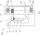
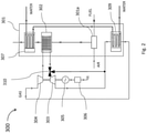
- a system 200, 300 is shown, according to the invention.
- the cogeneration system 200, 300 comprises: a boiler 201, 301 able to heat water preferably for a domestic use, comprising internally a combustor 201a, 301a of liquid or gaseous fuel; a compressor 204, 304; a heat exchanger 202, 302 for the exchange of thermal energy between the combustion fumes produced by the combustor 201a, 301a and a fluid coming out of the compressor 204, 304; a gas turbine working on a fluid compressed and heated by the heat exchanger 202, 302; a current generator 205, 305 and a current converter 206, 306 connected to the gas turbine 203, 303 able to produce electrical energy; and a main fumes / water exchanger 207, 307, placed after the heat exchanger 202, 302 able to recover the remaining part of the thermal energy produced by the combustion in the combustor 201a, 301a, contained in the combustion fumes and not absorbed by the heat exchanger 202, 302.
- the cogeneration system 200, 300 comprises, before the gas turbine 203, 303, a by-pass valve 210, 310 configured to adjust the part of the flow of the compressed and heated fluid entering the gas turbine 203, 303 and aimed at producing electrical energy.
- the remaining flow of the fluid in order to recover the thermal energy contained in it, is mixed with the one coming out of the gas turbine 203, 303 and sent to the heat exchanger 209, 309 in the systems 200, 300.
- the opening and closing of the by-pass valve 210, 310 is controlled through an electronic control unit depending on the present thermal and electrical needs.
- an electronic control unit works also on the amount of fuel to burn in the combustor 201a, 301a, in such a way as to avoid an excess of production of thermal and electrical energy compared with the current need.
- the system 200, 300 includes also a variable-geometry turbine, which in turn is driven through the electronic control unit.
- the heat exchanger 202 is a fumes/air heat exchanger in the system 200, and a fumes/gaseous fluid in the system 300.
- the heat exchanger 202, 302 is configured to absorb at least 5% of the thermal energy of the fumes so that they pass through the main fumes/water exchanger 207, 307 at a temperature greater than or equal to 320°C.
- the cogeneration system 200, 300 allows to use the cogeneration even in situations where the electric consumption with respect to fuel consumption (expressed in kWh) for heating is less than 30%, i.e.: 0.30 ⁇ electric kWh / thermal kWh .
- the cogeneration system 200, 300 can be applied to a condensing or conventional boiler, small or large, by making the appropriate changes.
- Figure 1 and 2 show a first and a second embodiment of the cogeneration system 200 and 300 comprising a boiler 201, 301 comprising a liquid or gaseous fuel combustor 201a, 301a, a fumes/air heat exchanger 202, 302 connected to the combustor 201a, 301a and a main fumes/water exchanger 207, 307 placed in series to the fumes/air exchanger 202, 302; a compressor 204, 304, for the compression of ambient air and for sending the same to the fumes/air exchanger 202, 302; and an external combustion open cycle gas turbine 203, 303, thermally supplied by the fumes/air exchanger 202, 302and connected to the combustor 201a, 301a.
- a boiler 201, 301 comprising a liquid or gaseous fuel combustor 201a, 301a, a fumes/air heat exchanger 202, 302 connected to the combustor 201
- the system 200, 300 absorbs a part of the thermal energy produced by combustion, converts it into electrical energy and recoverins the part of the thermal energy lost in such a conversion.
- the ratio between electrical kWh and thermal kWh is ⁇ 0,10, i.e., the average requirement of electrical energy in an apartment, in one year, is approximately equal to 10% of the requirement of gas used for heating (expressed in kWh). Therefore, under such conditions the fumes/air exchanger 202, 302 will absorb 10% of the thermal energy of the fumes, so that in the case of the boiler for domestic use, these will pass through the main fumes/water exchanger 207, 307 no more at 350°C, but at about 325°C.
- the main fumes/water exchanger 207, 307 is configured for heat recovery of the heat contained in the combustion fumes.
- a part of the thermal energy, preferably greater than 70% produced by the combustor 201a, 301a, not transferred to the fumes/air exchanger 202, 302, will be transferred, through the fumes, to the main fumes/water exchanger 207, 307 to heat water.
- the current generator 205, 305, generating continuous (DC) or alternating (AC) current, and the current converter 206, 306, whether it is a DC/DC, a DC/AC or an AC/AC converter, are able to produce electrical energy in compliance with the technical specifications of the electrical grid.
- the compressor 204, 304 compresses air taken from the environment and sends it to the fumes/air exchanger 202, 302 in which the air itself gets part of the thermal power generated by the combustor 201a, 301a in the boiler 201, 301.
- the air thus heated enters turbine 203, 303 where it expands, it generates energy that the generator 205, 305 (DC or AC) and the current converter 206, 306 will transform in electrical energy in compliance with the technical specifications of the electrical grid.
- the air coming out of the turbine 203, 303 is mixed with the combustion air in the boiler 201, 301.
- the residual thermal energy of the air leaving the turbine 203, 303 is recovered increasing the temperature of the combustion air supplying the combustor 201a, 301a of the boiler 201, 301, by mixing, or directly into the boiler 201, 301 to facilitate the achievement of the high temperatures.
- the system 200, 300 allows to achieve a production of mechanical energy by means of an open cycle gas turbine 203, 303 and, therefore, of electrical energy by means of the generator 205, 305 and the converter 206, 306, whose residual thermal power is recovered in the boiler together with the one present in the fluid that possibly has been redirected by the by-pass valve 210, 310.
- the overall efficiency of the system 200, 300 remains similar to the thermal efficiency of a classic boiler, but with a contemporary production of electrical energy to be exploited.
- the system 200, 300 produces electrical energy with percentages greater than 5% of the fed power, allowing the cogeneration even in situations where the thermal energy requirement (in the form of water or steam) and the electrical energy requirement is strongly unbalanced towards the first one.
- the system 200, 300 includes an additional heat exchanger 209, 309 able to recover the residual thermal energy of the fluid coming out of the turbine 203, 303 and of the one possibly diverted by the by-pass valve 210, 310, and to preheat the water that is to be heated and that enters the main exchanger 207, 307.
- the system 200 includes, an additional air/water heat exchanger 209 to which is connected the turbine 203 that in the system 200 is an external combustion closed cycle turbine 203.
- the air coming out of the turbine 203 mixing also with the air diverted by the by-pass valve 210, with its residual thermal energy, is provided to the air/water exchanger 209 where it gives away thermal energy directly to the water that is to be heated in the boiler.
- the additional exchanger 209, 309 allows a preheating of the water and therefore a reduction in the waiting time for the water to reach the desired temperature when it comes out of the boiler.
- the air is cooled and brought to a temperature, which may also be lower than the ambient temperature, such as to be taken by the compressor 204.
- the turbine cycle becomes a closed cycle having a global efficiency of the turbine/boiler unit close to the one of the first embodiment, with the advantage of a quicker water heating and of being able to use the air, in the turbine plant, with a minimum pressure higher than the atmospheric pressure so as to obtain smaller overall dimensions with the same output power or higher performances of the turbine and therefore a greater production of electrical energy (always remaining in the performance percentage range above indicated).
- the compressor 204 compresses the air and sends it to the heat exchanger 202 where the air gets a part of the thermal power produced by the combustor 201a in the boiler 201.
- the air heated in this way enters, with a flow adjusted by the by-pass valve 210, in the turbine 203 where it expands producing energy that the generator 205 (DC or AC) and the current converter 206 convert into electrical energy.
- the compressor 304 is supplied with an inert gaseous fluid, instead of air, characterized by more efficient features compared with those of the air for the purposes of the function to be carried out.
- the gas turbine 303 is an external combustion closed cycle turbine connected to the combustor 301a, and the additional heat exchanger 309 is a gaseous fluid/water exchanger placed at the output of the turbine 303, so that the residual thermal energy is transmitted to the gaseous fluid/water exchanger 309.
- the cogeneration system 200, 300 allows a regulated preheating of the water and therefore a reduction in the waiting time for the water to reach the desired temperature when it comes out of the boiler.
- the system is characterized by emissions of exhaust gases similar to those of a boiler, therefore very low compared to those that occur with other systems producing electrical energy.
- a further advantage of the system according to the invention is the constructive simplicity and the easy realization, with any size of power, and the possible diffusion in large scale.
- a further advantage of the system according to the invention is a quicker water heating and being able to use an inert gas, due to the fact that at the same time the inert gas is cooled and brought to a temperature, that may be even lower than the room temperature, so as to be taken back by the compressor.
- Another advantage of the cogeneration system according to the invention is that it is smaller for the same produced power and has higher performances of the turbine, and thus an increased production of electrical energy.
Landscapes
- Engineering & Computer Science (AREA)
- Combustion & Propulsion (AREA)
- Chemical & Material Sciences (AREA)
- General Engineering & Computer Science (AREA)
- Mechanical Engineering (AREA)
- Thermal Sciences (AREA)
- Physics & Mathematics (AREA)
- Power Engineering (AREA)
- Engine Equipment That Uses Special Cycles (AREA)
- Control Of Steam Boilers And Waste-Gas Boilers (AREA)
- Control Of Turbines (AREA)
- Instantaneous Water Boilers, Portable Hot-Water Supply Apparatuses, And Control Of Portable Hot-Water Supply Apparatuses (AREA)
- Heat-Pump Type And Storage Water Heaters (AREA)
Description
- The present invention relates to a cogeneration system .
- In particular, the present invention relates to a cogeneration system for example for a boiler for domestic use or for a steam-generating boiler.
- As it is known, a generic domestic boiler for hot water production uses the combustion of a fuel (liquid or gaseous) with air (oxidizing agent) usually at room temperature (Tamb). In general, in the boiler there is a combustion chamber, thermally insulated, in which is inserted a main exchanger in which the working fluid to be heated, typically water, flows at a temperature ranging between 15°C and 80°C.
- Cogeneration systems applied to boilers such as the one described in the patent application
CN105222203 , in which is described a heating device having a gas-steam cogeneration system, are known. - However, known cogeneration systems for boiler are not optimized for civil and domestic applications, and are cumbersome and expensive. Moreover, in the known cogeneration systems, once the power supplied through the combustion is fixed, the production of thermal energy is linked to the production of electrical energy, so that their ratio cannot be changed. As a consequence of this restriction if only the part of thermal energy should be increased it would be necessary to increase the supplied energy, and as a result also the production of electrical energy would be increased. In known systems, therefore, the amount of produced thermal energy is bond to the amount of electrical energy being produced.
- A solution trying to solve these problems is the patent application
DE102009057100 , which discloses an electrical energy-heat cogeneration system for small residential units having a gas turbine, a compressor and a generator. The expander of the gas turbine, the compressor and the generator are arranged on a common shaft. The gas for a shaft bearing is brought to a positive pressure through the compressor. The working gas is an inert gas such as helium. - A solution to these problems is described in the patent
GB1309589 - The problem of this solution is that the produced energy cannot be adjusted and cannot be divided into an electrical part and a thermal part in a variable manner.
- The purpose of the present invention is to provide a cogeneration system for a boiler that recovers the heat of the combustion fumes to convert it into electrical energy and into thermal energy allowing to modify according to the needs the ratio between the part to convert into electrical energy and the part aimed at producing thermal energy, this wat keeping fixed the overall yield at its maximum value, so that to overcome the limits of the known technical solutions.
- Furthermore, the object of the present invention is to provide a cogeneration system for a boiler that is efficient, economical and not bulky.
- Finally, the object of the present invention is to provide a cogeneration system for a boiler which allows the production of thermal energy and, if required, of electrical energy, keeping always fixed the overall yield.
- According to the present invention a cogeneration system is provided, as defined in claim 1.
- For a better understanding of the present invention is now described a preferred embodiment, purely by way of nonlimiting example, with reference to annexed drawings, in which:
-
figure 1 shows a block diagram of a first embodiment of the cogeneration system according to the invention; -
figure 2 shows a block diagram of a second embodiment of the cogeneration system according to the invention. - With reference to the figures, a
system - The
cogeneration system boiler combustor compressor heat exchanger combustor compressor heat exchanger current generator current converter gas turbine water exchanger heat exchanger combustor heat exchanger - The
cogeneration system gas turbine pass valve gas turbine gas turbine heat exchanger systems - According to an aspect of the invention, the opening and closing of the by-
pass valve combustor - According to an aspect of the invention, in addition to the by-
pass valve system - According to an aspect of the invention, the
heat exchanger 202, is a fumes/air heat exchanger in thesystem 200, and a fumes/gaseous fluid in thesystem 300. Theheat exchanger water exchanger - Advantageously, the
cogeneration system 
- Furthermore, advantageously, the
cogeneration system -
Figure 1 and2 show a first and a second embodiment of thecogeneration system boiler gaseous fuel combustor air heat exchanger combustor water exchanger air exchanger compressor air exchanger cycle gas turbine air exchanger 202, 302and connected to thecombustor - By placing the fumes/
air exchanger system - For example, in an apartment where a domestic boiler is used, the ratio between electrical kWh and thermal kWh is ≤0,10, i.e., the average requirement of electrical energy in an apartment, in one year, is approximately equal to 10% of the requirement of gas used for heating (expressed in kWh). Therefore, under such conditions the fumes/
air exchanger water exchanger - Advantageously according to the invention, the main fumes/
water exchanger - Advantageously according to the invention, a part of the thermal energy, preferably greater than 70% produced by the
combustor air exchanger water exchanger - According to an aspect of the invention, the
current generator current converter - In use, the
compressor air exchanger combustor boiler turbine generator 205, 305 (DC or AC) and thecurrent converter - According to an aspect of the invention, the air coming out of the
turbine boiler - Advantageously, the residual thermal energy of the air leaving the
turbine combustor boiler boiler - Advantageously, the
system cycle gas turbine generator converter pass valve system - Advantageously, the
system - Advantageously, keeping the overall efficiency fixed, it is possible to adjust both the amount of fuel to use and the part of production of electrical energy, by means of the by-
pass valve pass valve - The
system additional heat exchanger turbine pass valve main exchanger - In particular, the
system 200 includes, an additional air/water heat exchanger 209 to which is connected theturbine 203 that in thesystem 200 is an external combustion closedcycle turbine 203. In this case, the air coming out of theturbine 203, mixing also with the air diverted by the by-pass valve 210, with its residual thermal energy, is provided to the air/water exchanger 209 where it gives away thermal energy directly to the water that is to be heated in the boiler. - The
additional exchanger compressor 204. In this way the turbine cycle becomes a closed cycle having a global efficiency of the turbine/boiler unit close to the one of the first embodiment, with the advantage of a quicker water heating and of being able to use the air, in the turbine plant, with a minimum pressure higher than the atmospheric pressure so as to obtain smaller overall dimensions with the same output power or higher performances of the turbine and therefore a greater production of electrical energy (always remaining in the performance percentage range above indicated). - In use, in the
system 200 thecompressor 204 compresses the air and sends it to theheat exchanger 202 where the air gets a part of the thermal power produced by thecombustor 201a in theboiler 201. The air heated in this way enters, with a flow adjusted by the by-pass valve 210, in theturbine 203 where it expands producing energy that the generator 205 (DC or AC) and thecurrent converter 206 convert into electrical energy. - According to the second embodiment of the present invention, shown in
figure 2 , thecompressor 304 is supplied with an inert gaseous fluid, instead of air, characterized by more efficient features compared with those of the air for the purposes of the function to be carried out. - According to an aspect of the invention, the
gas turbine 303 is an external combustion closed cycle turbine connected to thecombustor 301a, and theadditional heat exchanger 309 is a gaseous fluid/water exchanger placed at the output of theturbine 303, so that the residual thermal energy is transmitted to the gaseous fluid/water exchanger 309. - Therefore, the
cogeneration system - Advantageously according to the invention, the system is characterized by emissions of exhaust gases similar to those of a boiler, therefore very low compared to those that occur with other systems producing electrical energy.
- A further advantage of the system according to the invention is the constructive simplicity and the easy realization, with any size of power, and the possible diffusion in large scale.
- A further advantage of the system according to the invention is a quicker water heating and being able to use an inert gas, due to the fact that at the same time the inert gas is cooled and brought to a temperature, that may be even lower than the room temperature, so as to be taken back by the compressor.
- Another advantage of the cogeneration system according to the invention is that it is smaller for the same produced power and has higher performances of the turbine, and thus an increased production of electrical energy.
- It is finally clear that the cogeneration system here described and illustrated may be subject to modifications and variations without thereby departing from the scope of the present invention, as defined in the appended claims.
Claims (3)
- Cogeneration system (200, 300) comprising:- a boiler (201, 301) able to heat water for domestic use;- a combustor (201a, 301a) of liquid or gaseous fuel, placed into the boiler (201, 301) from which combustion fumes come out;- a compressor (204, 304) for a gaseous fluid;- a heat exchanger (202, 302) able to exchange thermal energy between combustion fumes generated in the combustor (201a, 301a) and a fluid coming from the compressor (204, 304);- a gas turbine (203, 303) receiving the fluid compressed and heated from the heat exchanger (202, 302) ;- a current generator (205, 305) and a current converter (206, 306) connected to the gas turbine (203, 303) able to generate electrical energy;- a main fumes / water exchanger (207, 307) placed after the heat exchanger (202, 302) able to recover thermal energy between fumes generated in the combustor (201a, 301a) and water;- a by-pass valve (210, 310) placed before the turbine (203, 303), configured to adjust the flow rate of a portion of the fluid entering the gas turbine (203, 303) and the remaining flow of the fluid to be redirected;characterized in comprising an additional heat exchanger (209, 309) arranged to recover remaining thermal energy of the portion of the fluid sent out from the turbine (203, 303) and of the remaining flow of the fluid redirected by the by-pass valve (210, 310) and arranged to preheat water entering in the main heat exchanger (207, 307) .
- Cogeneration system (200, 300) according to claim 1, characterized in that the cogeneration system further comprises an electronic control unit, said by-pass valve (210, 310) being controlled in its opening and closing by said electronic control unit.
- Cogeneration system (200, 300) according to claim 1, characterized in that the heat exchanger (202, 302) is a fumes /gas exchanger configured to absorb at least 5% of the thermal energy of the fumes so that they pass through the main fumes/water exchanger (207, 307) at a temperature greater than or equal to 320°C.
Priority Applications (2)
| Application Number | Priority Date | Filing Date | Title |
|---|---|---|---|
| PL18839622T PL3728959T3 (en) | 2017-12-22 | 2018-12-19 | Cogeneration system for a boiler |
| RS20220474A RS63274B1 (en) | 2017-12-22 | 2018-12-19 | COGENERATION SYSTEM FOR BOILER |
Applications Claiming Priority (2)
| Application Number | Priority Date | Filing Date | Title |
|---|---|---|---|
| IT201700148827 | 2017-12-22 | ||
| PCT/IB2018/060325 WO2019123305A1 (en) | 2017-12-22 | 2018-12-19 | Cogeneration system for a boiler |
Publications (2)
| Publication Number | Publication Date |
|---|---|
| EP3728959A1 EP3728959A1 (en) | 2020-10-28 |
| EP3728959B1 true EP3728959B1 (en) | 2022-03-16 |
Family
ID=61868785
Family Applications (1)
| Application Number | Title | Priority Date | Filing Date |
|---|---|---|---|
| EP18839622.0A Active EP3728959B1 (en) | 2017-12-22 | 2018-12-19 | Cogeneration system for a boiler |
Country Status (10)
| Country | Link |
|---|---|
| US (1) | US11022035B2 (en) |
| EP (1) | EP3728959B1 (en) |
| JP (1) | JP7472035B2 (en) |
| KR (1) | KR102690627B1 (en) |
| CN (1) | CN111512096B (en) |
| ES (1) | ES2914625T3 (en) |
| HU (1) | HUE059153T2 (en) |
| PL (1) | PL3728959T3 (en) |
| RS (1) | RS63274B1 (en) |
| WO (1) | WO2019123305A1 (en) |
Families Citing this family (2)
| Publication number | Priority date | Publication date | Assignee | Title |
|---|---|---|---|---|
| PL244675B1 (en) | 2022-03-15 | 2024-02-19 | Aic Spolka Akcyjna | Cogeneration boiler |
| TR2022010075A1 (en) * | 2022-06-16 | 2023-12-21 | Ari Bayram | TURBO MACHINE |
Family Cites Families (54)
| Publication number | Priority date | Publication date | Assignee | Title |
|---|---|---|---|---|
| DE2009711C3 (en) * | 1970-03-02 | 1980-08-07 | Oemv Ag | Process and system for utilizing the energy content of the flue gas produced by catalytic cracking systems |
| US3965675A (en) * | 1974-08-08 | 1976-06-29 | Westinghouse Electric Corporation | Combined cycle electric power plant and a heat recovery steam generator having improved boiler feed pump flow control |
| US4289475A (en) * | 1977-01-05 | 1981-09-15 | Selas Corporation Of America | Steam vaporization of oil |
| US4353206A (en) * | 1980-08-20 | 1982-10-12 | Westinghouse Electric Corp. | Apparatus for removing NOx and for providing better plant efficiency in combined cycle plants |
| DE3731688A1 (en) * | 1987-09-21 | 1989-03-30 | Degussa | METHOD FOR THE CATALYTIC IMPROVEMENT OF HYDROCARBON, HALOGEN CARBON HYDROGEN AND CARBON MONOXIDE CONTAINING EXHAUST GASES |
| IT1227318B (en) * | 1988-07-29 | 1991-04-08 | Pietro Italiano | METHANE CATALYTIC COMBUSTION BOILER FOR OBTAINING HOT WATER FOR DOMESTIC AND INDUSTRIAL USES. |
| US5059405A (en) * | 1988-12-09 | 1991-10-22 | Bio-Gas Development, Inc. | Process and apparatus for purification of landfill gases |
| US6564556B2 (en) * | 1992-10-27 | 2003-05-20 | J. Lyell Ginter | High efficiency low pollution hybrid brayton cycle combustor |
| US5384051A (en) * | 1993-02-05 | 1995-01-24 | Mcginness; Thomas G. | Supercritical oxidation reactor |
| US5650128A (en) * | 1994-12-01 | 1997-07-22 | Thermatrix, Inc. | Method for destruction of volatile organic compound flows of varying concentration |
| US5847353A (en) * | 1995-02-02 | 1998-12-08 | Integrated Environmental Technologies, Llc | Methods and apparatus for low NOx emissions during the production of electricity from waste treatment systems |
| US6126913A (en) * | 1996-06-06 | 2000-10-03 | Thermatrix, Inc. | Thermal oxidizers with improved preheating means and processes for operating same |
| US5896740A (en) * | 1996-09-12 | 1999-04-27 | Shouman; Ahmad R. | Dual cycle turbine engine having increased efficiency and heat recovery system for use therein |
| JP2000054855A (en) * | 1998-08-07 | 2000-02-22 | Ebara Corp | External heating type gas turbine |
| US6393821B1 (en) * | 1998-08-21 | 2002-05-28 | Edan Prabhu | Method for collection and use of low-level methane emissions |
| DE10047262B4 (en) * | 2000-09-23 | 2005-12-01 | G.A.S. Energietechnologie Gmbh | Process for the use of methane-containing gases |
| AU2002249811B2 (en) * | 2000-10-30 | 2005-05-26 | Ztek Corporation | Multi-function energy system operable as a fuel cell, reformer, or thermal plant |
| US6748742B2 (en) * | 2000-11-07 | 2004-06-15 | Capstone Turbine Corporation | Microturbine combination systems |
| US6655137B1 (en) * | 2001-06-25 | 2003-12-02 | Amir A. Sardari | Advanced combined cycle co-generation abatement system |
| DE20220621U1 (en) | 2002-04-27 | 2003-12-24 | Öko-Insel Maschinenbau GmbH | Micro gas turbine for generation of electrical energy and heat has working medium heated by combustion gases from combustion chamber for combustion of biomass |
| WO2004011789A1 (en) * | 2002-07-25 | 2004-02-05 | Ingersoll-Rand Energy Systems Corporation | Microturbine for combustion of volatile organic compounds (vocs) |
| US6892542B2 (en) * | 2002-09-13 | 2005-05-17 | General Electric Company | Gas compression system and method for microturbine application |
| HUE059355T2 (en) * | 2002-10-10 | 2022-11-28 | Lpp Comb Llc | Process for vaporizing liquid fuels for combustion |
| US7007487B2 (en) * | 2003-07-31 | 2006-03-07 | Mes International, Inc. | Recuperated gas turbine engine system and method employing catalytic combustion |
| JP4581563B2 (en) * | 2004-08-31 | 2010-11-17 | 株式会社日立製作所 | Combined cycle power generation facilities, steam power generation facilities |
| JP4787715B2 (en) * | 2006-10-16 | 2011-10-05 | 株式会社荏原製作所 | Gas turbine equipment |
| JP4296200B2 (en) * | 2007-01-29 | 2009-07-15 | 大多喜ガス株式会社 | Hot water system |
| US8671658B2 (en) * | 2007-10-23 | 2014-03-18 | Ener-Core Power, Inc. | Oxidizing fuel |
| US8701413B2 (en) * | 2008-12-08 | 2014-04-22 | Ener-Core Power, Inc. | Oxidizing fuel in multiple operating modes |
| US20100275611A1 (en) * | 2009-05-01 | 2010-11-04 | Edan Prabhu | Distributing Fuel Flow in a Reaction Chamber |
| US8621869B2 (en) * | 2009-05-01 | 2014-01-07 | Ener-Core Power, Inc. | Heating a reaction chamber |
| JP5358329B2 (en) * | 2009-07-16 | 2013-12-04 | 本田技研工業株式会社 | Cogeneration equipment |
| DE102009057100B4 (en) | 2009-12-04 | 2012-12-20 | Klaus Affeld | Maintenance-free unit for combined heat and power |
| EP2547888A4 (en) * | 2010-03-15 | 2016-03-16 | Ener Core Power Inc | Processing fuel and water |
| US20120000200A1 (en) * | 2010-06-30 | 2012-01-05 | General Electric Company | Inert gas purging system for an orc heat recovery boiler |
| EA029301B1 (en) * | 2010-07-02 | 2018-03-30 | Эксонмобил Апстрим Рисерч Компани | Integrated systems for corecovery (embodiments) and method of generating power |
| TWI593878B (en) * | 2010-07-02 | 2017-08-01 | 艾克頌美孚上游研究公司 | Systems and methods for controlling combustion of a fuel |
| US20120039701A1 (en) | 2010-08-12 | 2012-02-16 | Nuovo Pignone S.P.A. | Closed Cycle Brayton Cycle System and Method |
| US9057028B2 (en) * | 2011-05-25 | 2015-06-16 | Ener-Core Power, Inc. | Gasifier power plant and management of wastes |
| DE102011111869A1 (en) | 2011-08-31 | 2013-02-28 | Christian Berger | Burner installed at heating boiler in e.g. residential plant, has burner main structure that is enclosed by sound-absorption and air filtration housing and is driven by turbine |
| JP5741524B2 (en) * | 2011-10-19 | 2015-07-01 | 株式会社豊田自動織機 | Rankine cycle |
| US9371993B2 (en) * | 2012-03-09 | 2016-06-21 | Ener-Core Power, Inc. | Gradual oxidation below flameout temperature |
| US9567903B2 (en) * | 2012-03-09 | 2017-02-14 | Ener-Core Power, Inc. | Gradual oxidation with heat transfer |
| US9194584B2 (en) * | 2012-03-09 | 2015-11-24 | Ener-Core Power, Inc. | Gradual oxidation with gradual oxidizer warmer |
| CN202993898U (en) * | 2012-12-21 | 2013-06-12 | 李书明 | Steam-water system of thermal power plant |
| TW201502356A (en) * | 2013-02-21 | 2015-01-16 | Exxonmobil Upstream Res Co | Reducing oxygen in a gas turbine exhaust |
| CN103233819B (en) * | 2013-04-11 | 2017-07-07 | 哈尔滨耦合动力工程技术中心有限公司 | Manifold type gas turbine frequency conversion generator cogeneration system and method for combined supply |
| US9381462B2 (en) * | 2013-07-01 | 2016-07-05 | General Electric Company | System and method for reducing emissions via solvent injection |
| US9683515B2 (en) * | 2013-07-02 | 2017-06-20 | Cummins, Inc. | Waste heat recovery system including a mechanism for collection, detection and removal of non-condensable gas |
| CN103644003A (en) | 2013-12-17 | 2014-03-19 | 汪禹 | Combined-cycle thermal power generation device with general fuel |
| CN105222203A (en) | 2015-11-04 | 2016-01-06 | 清华大学 | A kind of novel gas cogeneration of heat and power central heating device |
| JP6763520B2 (en) * | 2016-05-20 | 2020-09-30 | 三菱パワー株式会社 | Carbon-containing solid fuel gasification power generation facility and its carbon-containing solid fuel drying gas adjustment method |
| CN106224099B (en) * | 2016-09-20 | 2019-02-15 | 中国科学院工程热物理研究所 | A dual-fuel combined heat and power combined water injection forward and reverse gas turbine combined cycle system |
| JP6937217B2 (en) * | 2017-10-17 | 2021-09-22 | 三菱パワー株式会社 | Seawater leak detection device and method in water supply system and steam turbine plant |
-
2018
- 2018-12-19 KR KR1020207020297A patent/KR102690627B1/en active Active
- 2018-12-19 EP EP18839622.0A patent/EP3728959B1/en active Active
- 2018-12-19 PL PL18839622T patent/PL3728959T3/en unknown
- 2018-12-19 WO PCT/IB2018/060325 patent/WO2019123305A1/en not_active Ceased
- 2018-12-19 HU HUE18839622A patent/HUE059153T2/en unknown
- 2018-12-19 ES ES18839622T patent/ES2914625T3/en active Active
- 2018-12-19 CN CN201880083291.1A patent/CN111512096B/en active Active
- 2018-12-19 RS RS20220474A patent/RS63274B1/en unknown
- 2018-12-19 JP JP2020554594A patent/JP7472035B2/en active Active
- 2018-12-19 US US16/955,692 patent/US11022035B2/en active Active
Also Published As
| Publication number | Publication date |
|---|---|
| KR102690627B1 (en) | 2024-07-31 |
| EP3728959A1 (en) | 2020-10-28 |
| WO2019123305A1 (en) | 2019-06-27 |
| RU2020122345A3 (en) | 2022-03-14 |
| CN111512096A (en) | 2020-08-07 |
| KR20200104330A (en) | 2020-09-03 |
| JP7472035B2 (en) | 2024-04-22 |
| US20200309026A1 (en) | 2020-10-01 |
| PL3728959T3 (en) | 2022-06-13 |
| CN111512096B (en) | 2022-03-29 |
| US11022035B2 (en) | 2021-06-01 |
| ES2914625T3 (en) | 2022-06-14 |
| RS63274B1 (en) | 2022-06-30 |
| HUE059153T2 (en) | 2022-10-28 |
| JP2021509167A (en) | 2021-03-18 |
| CA3086644A1 (en) | 2019-06-27 |
| RU2020122345A (en) | 2022-01-24 |
Similar Documents
| Publication | Publication Date | Title |
|---|---|---|
| US4189922A (en) | Converting solar energy into electric power | |
| TW200506179A (en) | Thermodynamic cycles using thermal diluent | |
| MX340678B (en) | Thermodynamic cycles with thermal diluent. | |
| CN101865000A (en) | Combined power augmentation system and method | |
| WO2010147003A1 (en) | Solar thermal gas turbine power plant | |
| JP2012092835A (en) | System for generation of mechanical energy and/or electrical energy | |
| WO2011082949A3 (en) | Combined cycle power plant and method of operating such power plant | |
| US20070256424A1 (en) | Heat recovery gas turbine in combined brayton cycle power generation | |
| JP2010185454A (en) | Optimization of low-btu fuel-fired combined-cycle power plant by performance heating | |
| Poerner et al. | Waste heat recovery | |
| CN112412562B (en) | Photo-thermal cascade power generation system and method with combined cycle coupling of thermophotovoltaic and external combustion type fuel gas and steam | |
| EP3728959B1 (en) | Cogeneration system for a boiler | |
| CA3086644C (en) | Cogeneration system for a boiler | |
| EP2601394B1 (en) | Gas turbine apparatus with improved exergy recovery | |
| EP2899399A1 (en) | Solar power plant | |
| US20160115826A1 (en) | Combined cycle power plant | |
| JP2009097389A (en) | Decompression equipment with energy recovery function | |
| CN101701550B (en) | Gas turbine and alkali metal thermoelectric direct converter power generation device | |
| RU2772096C2 (en) | System for joint production of heat and electric energy for a boiler | |
| JP2012145110A (en) | Fuel reformer system for turbomachine system | |
| JP2009180101A (en) | Decompression equipment with energy recovery function | |
| JP3219186U (en) | Solar air power generation equipment | |
| WO2015187064A2 (en) | Multi-mode combined cycle power plant | |
| JP2012140872A (en) | Solar heat gas turbine and power generating equipment | |
| RU2012149900A (en) | COGENERATION GAS-TURBINE POWER INSTALLATION |
Legal Events
| Date | Code | Title | Description |
|---|---|---|---|
| STAA | Information on the status of an ep patent application or granted ep patent |
Free format text: STATUS: UNKNOWN |
|
| STAA | Information on the status of an ep patent application or granted ep patent |
Free format text: STATUS: THE INTERNATIONAL PUBLICATION HAS BEEN MADE |
|
| PUAI | Public reference made under article 153(3) epc to a published international application that has entered the european phase |
Free format text: ORIGINAL CODE: 0009012 |
|
| STAA | Information on the status of an ep patent application or granted ep patent |
Free format text: STATUS: REQUEST FOR EXAMINATION WAS MADE |
|
| 17P | Request for examination filed |
Effective date: 20200720 |
|
| AK | Designated contracting states |
Kind code of ref document: A1 Designated state(s): AL AT BE BG CH CY CZ DE DK EE ES FI FR GB GR HR HU IE IS IT LI LT LU LV MC MK MT NL NO PL PT RO RS SE SI SK SM TR |
|
| AX | Request for extension of the european patent |
Extension state: BA ME |
|
| DAV | Request for validation of the european patent (deleted) | ||
| DAX | Request for extension of the european patent (deleted) | ||
| GRAP | Despatch of communication of intention to grant a patent |
Free format text: ORIGINAL CODE: EPIDOSNIGR1 |
|
| STAA | Information on the status of an ep patent application or granted ep patent |
Free format text: STATUS: GRANT OF PATENT IS INTENDED |
|
| INTG | Intention to grant announced |
Effective date: 20211015 |
|
| RIC1 | Information provided on ipc code assigned before grant |
Ipc: F02C 7/08 20060101ALI20211001BHEP Ipc: F02C 6/18 20060101ALI20211001BHEP Ipc: F02C 1/04 20060101ALI20211001BHEP Ipc: F24H 1/12 20060101AFI20211001BHEP |
|
| GRAS | Grant fee paid |
Free format text: ORIGINAL CODE: EPIDOSNIGR3 |
|
| GRAA | (expected) grant |
Free format text: ORIGINAL CODE: 0009210 |
|
| STAA | Information on the status of an ep patent application or granted ep patent |
Free format text: STATUS: THE PATENT HAS BEEN GRANTED |
|
| AK | Designated contracting states |
Kind code of ref document: B1 Designated state(s): AL AT BE BG CH CY CZ DE DK EE ES FI FR GB GR HR HU IE IS IT LI LT LU LV MC MK MT NL NO PL PT RO RS SE SI SK SM TR |
|
| REG | Reference to a national code |
Ref country code: GB Ref legal event code: FG4D |
|
| REG | Reference to a national code |
Ref country code: CH Ref legal event code: EP |
|
| REG | Reference to a national code |
Ref country code: DE Ref legal event code: R096 Ref document number: 602018032461 Country of ref document: DE |
|
| REG | Reference to a national code |
Ref country code: IE Ref legal event code: FG4D |
|
| REG | Reference to a national code |
Ref country code: AT Ref legal event code: REF Ref document number: 1476159 Country of ref document: AT Kind code of ref document: T Effective date: 20220415 |
|
| REG | Reference to a national code |
Ref country code: RO Ref legal event code: EPE |
|
| REG | Reference to a national code |
Ref country code: NL Ref legal event code: FP |
|
| REG | Reference to a national code |
Ref country code: SE Ref legal event code: TRGR Ref country code: ES Ref legal event code: FG2A Ref document number: 2914625 Country of ref document: ES Kind code of ref document: T3 Effective date: 20220614 |
|
| REG | Reference to a national code |
Ref country code: LT Ref legal event code: MG9D |
|
| PG25 | Lapsed in a contracting state [announced via postgrant information from national office to epo] |
Ref country code: NO Free format text: LAPSE BECAUSE OF FAILURE TO SUBMIT A TRANSLATION OF THE DESCRIPTION OR TO PAY THE FEE WITHIN THE PRESCRIBED TIME-LIMIT Effective date: 20220616 Ref country code: LT Free format text: LAPSE BECAUSE OF FAILURE TO SUBMIT A TRANSLATION OF THE DESCRIPTION OR TO PAY THE FEE WITHIN THE PRESCRIBED TIME-LIMIT Effective date: 20220316 Ref country code: HR Free format text: LAPSE BECAUSE OF FAILURE TO SUBMIT A TRANSLATION OF THE DESCRIPTION OR TO PAY THE FEE WITHIN THE PRESCRIBED TIME-LIMIT Effective date: 20220316 Ref country code: BG Free format text: LAPSE BECAUSE OF FAILURE TO SUBMIT A TRANSLATION OF THE DESCRIPTION OR TO PAY THE FEE WITHIN THE PRESCRIBED TIME-LIMIT Effective date: 20220616 |
|
| REG | Reference to a national code |
Ref country code: AT Ref legal event code: MK05 Ref document number: 1476159 Country of ref document: AT Kind code of ref document: T Effective date: 20220316 |
|
| PG25 | Lapsed in a contracting state [announced via postgrant information from national office to epo] |
Ref country code: LV Free format text: LAPSE BECAUSE OF FAILURE TO SUBMIT A TRANSLATION OF THE DESCRIPTION OR TO PAY THE FEE WITHIN THE PRESCRIBED TIME-LIMIT Effective date: 20220316 Ref country code: GR Free format text: LAPSE BECAUSE OF FAILURE TO SUBMIT A TRANSLATION OF THE DESCRIPTION OR TO PAY THE FEE WITHIN THE PRESCRIBED TIME-LIMIT Effective date: 20220617 Ref country code: FI Free format text: LAPSE BECAUSE OF FAILURE TO SUBMIT A TRANSLATION OF THE DESCRIPTION OR TO PAY THE FEE WITHIN THE PRESCRIBED TIME-LIMIT Effective date: 20220316 |
|
| REG | Reference to a national code |
Ref country code: HU Ref legal event code: AG4A Ref document number: E059153 Country of ref document: HU |
|
| PG25 | Lapsed in a contracting state [announced via postgrant information from national office to epo] |
Ref country code: SM Free format text: LAPSE BECAUSE OF FAILURE TO SUBMIT A TRANSLATION OF THE DESCRIPTION OR TO PAY THE FEE WITHIN THE PRESCRIBED TIME-LIMIT Effective date: 20220316 Ref country code: SK Free format text: LAPSE BECAUSE OF FAILURE TO SUBMIT A TRANSLATION OF THE DESCRIPTION OR TO PAY THE FEE WITHIN THE PRESCRIBED TIME-LIMIT Effective date: 20220316 Ref country code: PT Free format text: LAPSE BECAUSE OF FAILURE TO SUBMIT A TRANSLATION OF THE DESCRIPTION OR TO PAY THE FEE WITHIN THE PRESCRIBED TIME-LIMIT Effective date: 20220718 Ref country code: EE Free format text: LAPSE BECAUSE OF FAILURE TO SUBMIT A TRANSLATION OF THE DESCRIPTION OR TO PAY THE FEE WITHIN THE PRESCRIBED TIME-LIMIT Effective date: 20220316 Ref country code: AT Free format text: LAPSE BECAUSE OF FAILURE TO SUBMIT A TRANSLATION OF THE DESCRIPTION OR TO PAY THE FEE WITHIN THE PRESCRIBED TIME-LIMIT Effective date: 20220316 |
|
| PG25 | Lapsed in a contracting state [announced via postgrant information from national office to epo] |
Ref country code: IS Free format text: LAPSE BECAUSE OF FAILURE TO SUBMIT A TRANSLATION OF THE DESCRIPTION OR TO PAY THE FEE WITHIN THE PRESCRIBED TIME-LIMIT Effective date: 20220716 |
|
| REG | Reference to a national code |
Ref country code: DE Ref legal event code: R097 Ref document number: 602018032461 Country of ref document: DE |
|
| PLBE | No opposition filed within time limit |
Free format text: ORIGINAL CODE: 0009261 |
|
| STAA | Information on the status of an ep patent application or granted ep patent |
Free format text: STATUS: NO OPPOSITION FILED WITHIN TIME LIMIT |
|
| PG25 | Lapsed in a contracting state [announced via postgrant information from national office to epo] |
Ref country code: DK Free format text: LAPSE BECAUSE OF FAILURE TO SUBMIT A TRANSLATION OF THE DESCRIPTION OR TO PAY THE FEE WITHIN THE PRESCRIBED TIME-LIMIT Effective date: 20220316 |
|
| 26N | No opposition filed |
Effective date: 20221219 |
|
| PG25 | Lapsed in a contracting state [announced via postgrant information from national office to epo] |
Ref country code: SI Free format text: LAPSE BECAUSE OF FAILURE TO SUBMIT A TRANSLATION OF THE DESCRIPTION OR TO PAY THE FEE WITHIN THE PRESCRIBED TIME-LIMIT Effective date: 20220316 |
|
| P01 | Opt-out of the competence of the unified patent court (upc) registered |
Effective date: 20230726 |
|
| PG25 | Lapsed in a contracting state [announced via postgrant information from national office to epo] |
Ref country code: LU Free format text: LAPSE BECAUSE OF NON-PAYMENT OF DUE FEES Effective date: 20221219 |
|
| PG25 | Lapsed in a contracting state [announced via postgrant information from national office to epo] |
Ref country code: IE Free format text: LAPSE BECAUSE OF NON-PAYMENT OF DUE FEES Effective date: 20221219 |
|
| PG25 | Lapsed in a contracting state [announced via postgrant information from national office to epo] |
Ref country code: CY Free format text: LAPSE BECAUSE OF FAILURE TO SUBMIT A TRANSLATION OF THE DESCRIPTION OR TO PAY THE FEE WITHIN THE PRESCRIBED TIME-LIMIT Effective date: 20220316 |
|
| PG25 | Lapsed in a contracting state [announced via postgrant information from national office to epo] |
Ref country code: MK Free format text: LAPSE BECAUSE OF FAILURE TO SUBMIT A TRANSLATION OF THE DESCRIPTION OR TO PAY THE FEE WITHIN THE PRESCRIBED TIME-LIMIT Effective date: 20220316 |
|
| PG25 | Lapsed in a contracting state [announced via postgrant information from national office to epo] |
Ref country code: MC Free format text: LAPSE BECAUSE OF FAILURE TO SUBMIT A TRANSLATION OF THE DESCRIPTION OR TO PAY THE FEE WITHIN THE PRESCRIBED TIME-LIMIT Effective date: 20220316 |
|
| PG25 | Lapsed in a contracting state [announced via postgrant information from national office to epo] |
Ref country code: TR Free format text: LAPSE BECAUSE OF FAILURE TO SUBMIT A TRANSLATION OF THE DESCRIPTION OR TO PAY THE FEE WITHIN THE PRESCRIBED TIME-LIMIT Effective date: 20220316 Ref country code: MC Free format text: LAPSE BECAUSE OF FAILURE TO SUBMIT A TRANSLATION OF THE DESCRIPTION OR TO PAY THE FEE WITHIN THE PRESCRIBED TIME-LIMIT Effective date: 20220316 |
|
| PG25 | Lapsed in a contracting state [announced via postgrant information from national office to epo] |
Ref country code: MT Free format text: LAPSE BECAUSE OF FAILURE TO SUBMIT A TRANSLATION OF THE DESCRIPTION OR TO PAY THE FEE WITHIN THE PRESCRIBED TIME-LIMIT Effective date: 20220316 |
|
| REG | Reference to a national code |
Ref country code: CH Ref legal event code: U11 Free format text: ST27 STATUS EVENT CODE: U-0-0-U10-U11 (AS PROVIDED BY THE NATIONAL OFFICE) Effective date: 20260101 |
|
| PGFP | Annual fee paid to national office [announced via postgrant information from national office to epo] |
Ref country code: DE Payment date: 20251211 Year of fee payment: 8 |
|
| PGFP | Annual fee paid to national office [announced via postgrant information from national office to epo] |
Ref country code: GB Payment date: 20251219 Year of fee payment: 8 |
|
| PGFP | Annual fee paid to national office [announced via postgrant information from national office to epo] |
Ref country code: IT Payment date: 20251209 Year of fee payment: 8 |
|
| PGFP | Annual fee paid to national office [announced via postgrant information from national office to epo] |
Ref country code: HU Payment date: 20251223 Year of fee payment: 8 Ref country code: NL Payment date: 20251219 Year of fee payment: 8 Ref country code: FR Payment date: 20251229 Year of fee payment: 8 |
|
| PGFP | Annual fee paid to national office [announced via postgrant information from national office to epo] |
Ref country code: AL Payment date: 20251218 Year of fee payment: 8 Ref country code: BE Payment date: 20251219 Year of fee payment: 8 |
|
| PGFP | Annual fee paid to national office [announced via postgrant information from national office to epo] |
Ref country code: SE Payment date: 20251219 Year of fee payment: 8 |
|
| PGFP | Annual fee paid to national office [announced via postgrant information from national office to epo] |
Ref country code: CZ Payment date: 20251217 Year of fee payment: 8 |
|
| PGFP | Annual fee paid to national office [announced via postgrant information from national office to epo] |
Ref country code: PL Payment date: 20251215 Year of fee payment: 8 |
|
| PGFP | Annual fee paid to national office [announced via postgrant information from national office to epo] |
Ref country code: RO Payment date: 20251216 Year of fee payment: 8 |
|
| PGFP | Annual fee paid to national office [announced via postgrant information from national office to epo] |
Ref country code: RS Payment date: 20251212 Year of fee payment: 8 |
|
| PGFP | Annual fee paid to national office [announced via postgrant information from national office to epo] |
Ref country code: ES Payment date: 20260130 Year of fee payment: 8 |
|
| PGFP | Annual fee paid to national office [announced via postgrant information from national office to epo] |
Ref country code: CH Payment date: 20260101 Year of fee payment: 8 |