EP3728800B1 - Kraftwerk - Google Patents
Kraftwerk Download PDFInfo
- Publication number
- EP3728800B1 EP3728800B1 EP18826986.4A EP18826986A EP3728800B1 EP 3728800 B1 EP3728800 B1 EP 3728800B1 EP 18826986 A EP18826986 A EP 18826986A EP 3728800 B1 EP3728800 B1 EP 3728800B1
- Authority
- EP
- European Patent Office
- Prior art keywords
- steam
- residual
- power plant
- feed water
- pressure
- Prior art date
- Legal status (The legal status is an assumption and is not a legal conclusion. Google has not performed a legal analysis and makes no representation as to the accuracy of the status listed.)
- Active
Links
- XLYOFNOQVPJJNP-UHFFFAOYSA-N water Substances O XLYOFNOQVPJJNP-UHFFFAOYSA-N 0.000 claims description 111
- 238000000034 method Methods 0.000 claims description 49
- UGFAIRIUMAVXCW-UHFFFAOYSA-N Carbon monoxide Chemical compound [O+]#[C-] UGFAIRIUMAVXCW-UHFFFAOYSA-N 0.000 claims description 47
- 239000003546 flue gas Substances 0.000 claims description 46
- 239000013505 freshwater Substances 0.000 claims description 17
- 239000007789 gas Substances 0.000 claims description 17
- 238000011084 recovery Methods 0.000 claims description 16
- 238000001816 cooling Methods 0.000 claims description 10
- 238000000926 separation method Methods 0.000 claims description 9
- 238000010304 firing Methods 0.000 claims description 7
- 239000002918 waste heat Substances 0.000 claims description 4
- 238000001704 evaporation Methods 0.000 claims description 3
- 239000000446 fuel Substances 0.000 claims description 3
- 238000010438 heat treatment Methods 0.000 claims description 2
- 230000005494 condensation Effects 0.000 claims 1
- 238000009833 condensation Methods 0.000 claims 1
- QAOWNCQODCNURD-UHFFFAOYSA-N Sulfuric acid Chemical compound OS(O)(=O)=O QAOWNCQODCNURD-UHFFFAOYSA-N 0.000 description 10
- 238000002347 injection Methods 0.000 description 5
- 239000007924 injection Substances 0.000 description 5
- 238000005086 pumping Methods 0.000 description 5
- 230000001105 regulatory effect Effects 0.000 description 5
- 238000010586 diagram Methods 0.000 description 3
- 238000000605 extraction Methods 0.000 description 3
- 239000002737 fuel gas Substances 0.000 description 3
- 238000004519 manufacturing process Methods 0.000 description 3
- 238000010248 power generation Methods 0.000 description 2
- 230000015572 biosynthetic process Effects 0.000 description 1
- 239000003990 capacitor Substances 0.000 description 1
- 238000005260 corrosion Methods 0.000 description 1
- 230000007797 corrosion Effects 0.000 description 1
- 230000001419 dependent effect Effects 0.000 description 1
- 238000011161 development Methods 0.000 description 1
- 230000018109 developmental process Effects 0.000 description 1
- 230000000694 effects Effects 0.000 description 1
- 230000005611 electricity Effects 0.000 description 1
- 230000008020 evaporation Effects 0.000 description 1
- 239000000284 extract Substances 0.000 description 1
- 238000010079 rubber tapping Methods 0.000 description 1
- 238000009423 ventilation Methods 0.000 description 1
- 239000002699 waste material Substances 0.000 description 1
Images
Classifications
-
- F—MECHANICAL ENGINEERING; LIGHTING; HEATING; WEAPONS; BLASTING
- F01—MACHINES OR ENGINES IN GENERAL; ENGINE PLANTS IN GENERAL; STEAM ENGINES
- F01K—STEAM ENGINE PLANTS; STEAM ACCUMULATORS; ENGINE PLANTS NOT OTHERWISE PROVIDED FOR; ENGINES USING SPECIAL WORKING FLUIDS OR CYCLES
- F01K23/00—Plants characterised by more than one engine delivering power external to the plant, the engines being driven by different fluids
- F01K23/02—Plants characterised by more than one engine delivering power external to the plant, the engines being driven by different fluids the engine cycles being thermally coupled
- F01K23/06—Plants characterised by more than one engine delivering power external to the plant, the engines being driven by different fluids the engine cycles being thermally coupled combustion heat from one cycle heating the fluid in another cycle
- F01K23/10—Plants characterised by more than one engine delivering power external to the plant, the engines being driven by different fluids the engine cycles being thermally coupled combustion heat from one cycle heating the fluid in another cycle with exhaust fluid of one cycle heating the fluid in another cycle
-
- F—MECHANICAL ENGINEERING; LIGHTING; HEATING; WEAPONS; BLASTING
- F01—MACHINES OR ENGINES IN GENERAL; ENGINE PLANTS IN GENERAL; STEAM ENGINES
- F01D—NON-POSITIVE DISPLACEMENT MACHINES OR ENGINES, e.g. STEAM TURBINES
- F01D15/00—Adaptations of machines or engines for special use; Combinations of engines with devices driven thereby
- F01D15/10—Adaptations for driving, or combinations with, electric generators
-
- F—MECHANICAL ENGINEERING; LIGHTING; HEATING; WEAPONS; BLASTING
- F01—MACHINES OR ENGINES IN GENERAL; ENGINE PLANTS IN GENERAL; STEAM ENGINES
- F01K—STEAM ENGINE PLANTS; STEAM ACCUMULATORS; ENGINE PLANTS NOT OTHERWISE PROVIDED FOR; ENGINES USING SPECIAL WORKING FLUIDS OR CYCLES
- F01K11/00—Plants characterised by the engines being structurally combined with boilers or condensers
-
- F—MECHANICAL ENGINEERING; LIGHTING; HEATING; WEAPONS; BLASTING
- F01—MACHINES OR ENGINES IN GENERAL; ENGINE PLANTS IN GENERAL; STEAM ENGINES
- F01K—STEAM ENGINE PLANTS; STEAM ACCUMULATORS; ENGINE PLANTS NOT OTHERWISE PROVIDED FOR; ENGINES USING SPECIAL WORKING FLUIDS OR CYCLES
- F01K17/00—Using steam or condensate extracted or exhausted from steam engine plant
- F01K17/04—Using steam or condensate extracted or exhausted from steam engine plant for specific purposes other than heating
-
- F—MECHANICAL ENGINEERING; LIGHTING; HEATING; WEAPONS; BLASTING
- F01—MACHINES OR ENGINES IN GENERAL; ENGINE PLANTS IN GENERAL; STEAM ENGINES
- F01K—STEAM ENGINE PLANTS; STEAM ACCUMULATORS; ENGINE PLANTS NOT OTHERWISE PROVIDED FOR; ENGINES USING SPECIAL WORKING FLUIDS OR CYCLES
- F01K19/00—Regenerating or otherwise treating steam exhausted from steam engine plant
-
- F—MECHANICAL ENGINEERING; LIGHTING; HEATING; WEAPONS; BLASTING
- F01—MACHINES OR ENGINES IN GENERAL; ENGINE PLANTS IN GENERAL; STEAM ENGINES
- F01K—STEAM ENGINE PLANTS; STEAM ACCUMULATORS; ENGINE PLANTS NOT OTHERWISE PROVIDED FOR; ENGINES USING SPECIAL WORKING FLUIDS OR CYCLES
- F01K23/00—Plants characterised by more than one engine delivering power external to the plant, the engines being driven by different fluids
- F01K23/02—Plants characterised by more than one engine delivering power external to the plant, the engines being driven by different fluids the engine cycles being thermally coupled
- F01K23/06—Plants characterised by more than one engine delivering power external to the plant, the engines being driven by different fluids the engine cycles being thermally coupled combustion heat from one cycle heating the fluid in another cycle
- F01K23/10—Plants characterised by more than one engine delivering power external to the plant, the engines being driven by different fluids the engine cycles being thermally coupled combustion heat from one cycle heating the fluid in another cycle with exhaust fluid of one cycle heating the fluid in another cycle
- F01K23/101—Regulating means specially adapted therefor
-
- F—MECHANICAL ENGINEERING; LIGHTING; HEATING; WEAPONS; BLASTING
- F01—MACHINES OR ENGINES IN GENERAL; ENGINE PLANTS IN GENERAL; STEAM ENGINES
- F01K—STEAM ENGINE PLANTS; STEAM ACCUMULATORS; ENGINE PLANTS NOT OTHERWISE PROVIDED FOR; ENGINES USING SPECIAL WORKING FLUIDS OR CYCLES
- F01K7/00—Steam engine plants characterised by the use of specific types of engine; Plants or engines characterised by their use of special steam systems, cycles or processes; Control means specially adapted for such systems, cycles or processes; Use of withdrawn or exhaust steam for feed-water heating
- F01K7/34—Steam engine plants characterised by the use of specific types of engine; Plants or engines characterised by their use of special steam systems, cycles or processes; Control means specially adapted for such systems, cycles or processes; Use of withdrawn or exhaust steam for feed-water heating the engines being of extraction or non-condensing type; Use of steam for feed-water heating
-
- F—MECHANICAL ENGINEERING; LIGHTING; HEATING; WEAPONS; BLASTING
- F22—STEAM GENERATION
- F22D—PREHEATING, OR ACCUMULATING PREHEATED, FEED-WATER FOR STEAM GENERATION; FEED-WATER SUPPLY FOR STEAM GENERATION; CONTROLLING WATER LEVEL FOR STEAM GENERATION; AUXILIARY DEVICES FOR PROMOTING WATER CIRCULATION WITHIN STEAM BOILERS
- F22D5/00—Controlling water feed or water level; Automatic water feeding or water-level regulators
-
- F—MECHANICAL ENGINEERING; LIGHTING; HEATING; WEAPONS; BLASTING
- F01—MACHINES OR ENGINES IN GENERAL; ENGINE PLANTS IN GENERAL; STEAM ENGINES
- F01K—STEAM ENGINE PLANTS; STEAM ACCUMULATORS; ENGINE PLANTS NOT OTHERWISE PROVIDED FOR; ENGINES USING SPECIAL WORKING FLUIDS OR CYCLES
- F01K23/00—Plants characterised by more than one engine delivering power external to the plant, the engines being driven by different fluids
- F01K23/02—Plants characterised by more than one engine delivering power external to the plant, the engines being driven by different fluids the engine cycles being thermally coupled
- F01K23/06—Plants characterised by more than one engine delivering power external to the plant, the engines being driven by different fluids the engine cycles being thermally coupled combustion heat from one cycle heating the fluid in another cycle
- F01K23/10—Plants characterised by more than one engine delivering power external to the plant, the engines being driven by different fluids the engine cycles being thermally coupled combustion heat from one cycle heating the fluid in another cycle with exhaust fluid of one cycle heating the fluid in another cycle
- F01K23/103—Plants characterised by more than one engine delivering power external to the plant, the engines being driven by different fluids the engine cycles being thermally coupled combustion heat from one cycle heating the fluid in another cycle with exhaust fluid of one cycle heating the fluid in another cycle with afterburner in exhaust boiler
-
- Y—GENERAL TAGGING OF NEW TECHNOLOGICAL DEVELOPMENTS; GENERAL TAGGING OF CROSS-SECTIONAL TECHNOLOGIES SPANNING OVER SEVERAL SECTIONS OF THE IPC; TECHNICAL SUBJECTS COVERED BY FORMER USPC CROSS-REFERENCE ART COLLECTIONS [XRACs] AND DIGESTS
- Y02—TECHNOLOGIES OR APPLICATIONS FOR MITIGATION OR ADAPTATION AGAINST CLIMATE CHANGE
- Y02E—REDUCTION OF GREENHOUSE GAS [GHG] EMISSIONS, RELATED TO ENERGY GENERATION, TRANSMISSION OR DISTRIBUTION
- Y02E20/00—Combustion technologies with mitigation potential
- Y02E20/14—Combined heat and power generation [CHP]
-
- Y—GENERAL TAGGING OF NEW TECHNOLOGICAL DEVELOPMENTS; GENERAL TAGGING OF CROSS-SECTIONAL TECHNOLOGIES SPANNING OVER SEVERAL SECTIONS OF THE IPC; TECHNICAL SUBJECTS COVERED BY FORMER USPC CROSS-REFERENCE ART COLLECTIONS [XRACs] AND DIGESTS
- Y02—TECHNOLOGIES OR APPLICATIONS FOR MITIGATION OR ADAPTATION AGAINST CLIMATE CHANGE
- Y02E—REDUCTION OF GREENHOUSE GAS [GHG] EMISSIONS, RELATED TO ENERGY GENERATION, TRANSMISSION OR DISTRIBUTION
- Y02E20/00—Combustion technologies with mitigation potential
- Y02E20/16—Combined cycle power plant [CCPP], or combined cycle gas turbine [CCGT]
-
- Y—GENERAL TAGGING OF NEW TECHNOLOGICAL DEVELOPMENTS; GENERAL TAGGING OF CROSS-SECTIONAL TECHNOLOGIES SPANNING OVER SEVERAL SECTIONS OF THE IPC; TECHNICAL SUBJECTS COVERED BY FORMER USPC CROSS-REFERENCE ART COLLECTIONS [XRACs] AND DIGESTS
- Y02—TECHNOLOGIES OR APPLICATIONS FOR MITIGATION OR ADAPTATION AGAINST CLIMATE CHANGE
- Y02P—CLIMATE CHANGE MITIGATION TECHNOLOGIES IN THE PRODUCTION OR PROCESSING OF GOODS
- Y02P80/00—Climate change mitigation technologies for sector-wide applications
- Y02P80/10—Efficient use of energy, e.g. using compressed air or pressurized fluid as energy carrier
- Y02P80/15—On-site combined power, heat or cool generation or distribution, e.g. combined heat and power [CHP] supply
Definitions
- the invention relates to a power plant for generating electrical energy and extraction steam (gas and steam power plant).
- the power plant according to the invention is provided with a gas turbine and works according to the combined heat and power system.
- an amount of extraction steam is maximized.
- fuel can be saved in the gas turbine or an additional firing system, since the required process steam is provided using less energy. In this way, both the operating costs of the power plant and its CO2 emissions can be reduced.
- Gas and steam power plants with combined heat and power generation are known from the prior art. For example, from the U.S. 5,044,163A such a power plant. However, no removal of process steam is planned for this power plant. Power plants in which process steam can be extracted are also known from the prior art. Typically, such power plants are built specifically for industrial consumers of electricity and heat. Heat is given off in the form of process steam. Advantageously, the consumers have a continuous need for energy. Such power plants have a gas turbine whose flue gas is used to evaporate feed water, with the live steam thus generated driving a steam turbine. After passing through the steam turbine, the residual steam can be extracted from the power plant as process steam and can be used for other processes.
- the task is thus solved by a power plant for generating electrical energy and process steam.
- the power plant includes a gas turbine, a steam turbine and a heat recovery steam generator.
- the waste heat steam generator is designed in at least one stage and can, in particular, also be designed in multiple stages.
- the gas turbine is used to drive a first generator to generate electrical energy by burning a fuel to form flue gas.
- the steam turbine is used to drive a second generator.
- the steam turbine has at least a first stage, in particular a high-pressure stage, in order to convert live steam into residual steam. In this way, energy is extracted from the live steam to drive the generator.
- the residual steam represents at least part of the process steam that can be extracted from the power plant.
- the heat recovery steam generator is used to generate live steam from fresh water using waste heat from the flue gas.
- the fresh water can either be supplied to the power plant, in particular to compensate for process steam that has been removed, and/or can be obtained from part of the residual steam by condensing it.
- the heat recovery steam generator comprises a plurality of heat exchangers in order to convert the fresh water into the fresh steam. Provision is made for the residual steam to have a residual steam pressure which is lower than a live steam pressure of the live steam. The live steam thus has more energy than the residual steam, which can be used in the steam turbine to drive the second generator.
- the steam turbine can only have the first stage, in particular the high-pressure stage. In this case, the steam turbine is designed in one stage. Alternatively, the steam turbine can also have an additional second stage, in particular a low-pressure stage. In this case, the steam turbine is designed in two stages.
- the heat recovery steam generator has a preheater and an evaporator.
- the preheater is used to preheat the fresh water into feed water.
- the evaporator serves to evaporate the feed water into the live steam.
- the preheater and the evaporator each comprise a heat exchanger which is introduced into a flow of the flue gas.
- the evaporator is arranged at a hotter point in the flow of flue gas than the preheater.
- the feed water has a feed water pressure that is higher than the residual steam pressure.
- the feed water pressure is built up in particular by a pump unit, through which fresh water can be pumped through the preheater.
- the feed water pressure is particularly advantageously a pressure of between 50 bar and 150 bar, preferably between 80 bar and 120 bar, particularly around 100 bar.
- the residual vapor pressure is in particular a pressure between 1 bar and 10 bar, in particular between 3 bar and 7 bar, particularly preferably around 5 bar.
- the live-steam pressure at full load is in particular the feedwater pressure minus 2 bar to 5 bar pressure loss, and in part-load operation it is in particular a pressure of between 10 bar and 20 bar, in particular between 13 bar and 17 bar, particularly preferably around 15 bar.
- the power plant also has a throttle valve or several throttle valves in stages and preferably at least one water separator.
- the at least one throttle valve is designed to relieve part of the feed water.
- the throttle valve can either be designed to expand part of the feed water to the residual steam pressure, or alternatively to a driving steam pressure.
- additional steam is generated that has the same steam pressure as the process steam.
- the additional steam as well as the process steam can be removed from the power plant in order to increase steam removal.
- a drive steam is generated.
- the drive steam is used in particular to operate a second stage of the steam turbine.
- the drive steam pressure is lower than the residual steam pressure.
- the drive steam pressure is a pressure between 0.1 bar and 3 bar, in particular between 0.3 bar and 0.7 bar, particularly preferably around 0.5 bar.
- the driving steam pressure is in particular lower than in full-load operation.
- the driving steam pressure is preferably considerably lower in part-load operation than in full-load operation.
- the second stage of the steam turbine is in particular a low-pressure stage, which is why the lower drive steam pressure is sufficient to drive the steam turbine, in particular at minimum mass flow.
- no residual steam discharged from the first stage needs to be used to drive the second stage. Rather, it is possible for the entire residual steam to be output as process steam.
- the power plant according to the invention significantly increases efficiency, particularly in part-load operation. This happens because steam extraction from the power plant is increased by increasing the amount of process steam. This is achieved by either extracting the additional steam as process steam in addition to the residual steam, or by not having to operate a second stage of the steam turbine with the residual steam from the first stage, or only to a lesser extent, which means that a larger proportion of the residual steam can be extracted as process steam. Since the power plant provides for feed water to be removed before evaporation, a higher flow rate can be realized through the preheater without significantly affecting the steam production. The higher flow of fresh water through the preheater results in improved cooling of the flue gas, so that the thermal energy of the flue gas can be optimally used even at lower temperatures.
- a control device in which the mass flow of the fresh water and the flow of the feed water is regulated by the throttle valve in such a way that the flow through the evaporator remains unaffected by the measure and at the same time the flue gas is optimally cooled.
- Optimum cooling of the flue gas occurs in particular when the flue gas is cooled down to 100°C, preferably down to 90°C.
- the cooling takes place down to a sulfuric acid dew point or up to a predefined tolerance range around the sulfuric acid dew point, with the sulfuric acid dew point in particular not being fallen below in order to avoid corrosion.
- the throttle valve is an additional steam throttle valve.
- the additional steam throttle valve is used to expand part of the feed water to the residual steam pressure for generating the additional steam. It is thus provided that after the expansion of part of the feed water to the residual steam pressure, the additional steam removed from the power plant. For this purpose, the additional steam is mixed with the residual steam pressure to form the process steam.
- the power plant is thus designed so that the additional steam can be mixed with the residual steam to form the process steam.
- the amount of process steam that can be extracted from the power plant is increased.
- the increased amount of process steam results from a higher mass flow through the preheater, it is possible to cool the flue gas to a low temperature. In particular, the flue gas is cooled to a lower temperature than in the prior art, thereby extracting a greater amount of thermal energy from the flue gas. The existing energy of the flue gas can thus be used better than in the prior art.
- the steam turbine is designed in two stages.
- the steam turbine thus has a second stage in addition to the first stage described above.
- the second stage is, in particular, a low-pressure stage and is used to convert drive steam into lost steam.
- the lost vapor is only intended for condensing and is not used further in particular.
- the drive steam can advantageously be generated by expanding residual water from the additional steam at a drive steam throttle valve.
- the drive steam generated in this way corresponds to the drive steam described above, with the drive steam not being generated directly from the feed water in this exemplary embodiment, but from the residual water in the additional steam.
- the residual water is separated from the additional steam and expanded again by the drive steam throttle valve.
- the second stage in particular the low-pressure stage, typically has a minimum mass flow which must not be fallen below to avoid ventilation. For example, the limit of 10% of the mass flow must not be undershot. In the prior art, this minimum mass flow is usually branched off from the residual steam and therefore cannot be used for the process steam. If the second stage is operated with the minimum mass flow, however, there is already a low pressure at its inlet due to Stodola's law, since there is a low pressure drop across the second stage of the turbine.
- the drive steam pressure is lower than the residual steam pressure, so that in the prior art the residual steam has to be severely throttled in order to reach the drive steam pressure. Therefore, the minimum mass flow can be optimally obtained from the additional steam, so that the residual steam does not have to be used to drive the second stage.
- the preheater is to be designed for full-load operation, which means that the preheater is oversized in partial-load operation. This is exploited by the higher flow of fresh water through the preheater to generate the additional steam and/or drive steam.
- the steam turbine is in turn designed in two stages, with the second stage, in particular a low-pressure stage, being designed to convert the drive steam into lost steam.
- the lost vapor is intended for condensing and, in particular, is not used any further.
- the drive steam is advantageously generated by the throttle valve, which is a drive steam throttle valve. This is done in that part of the feed water is expanded to the drive steam pressure, as a result of which the drive steam is generated by the drive steam throttle valve. In this case there is no Generating additional steam so that the residual steam represents the entire process steam. However, since no residual steam has to be used to drive the second stage, but rather the second stage is driven by the drive steam, the entire residual steam can represent the process steam.
- the electrical efficiency of the power plant in particular with a single-stage steam turbine, can be increased compared to a conventional power plant without an additional steam throttle valve, in that the process steam is advantageously provided completely by the additional steam and thus via the additional steam throttle valve. There is therefore no output of residual steam as process steam.
- the entire residual steam can thus be discharged via a bypass, in particular passed into the condenser.
- the residual steam can have a significantly lower pressure than a required process steam pressure, as a result of which the power output of the steam turbine is increased.
- the power plant advantageously has a feedwater pumping device.
- the feed water pump device is used to pump fresh water through the preheater and to generate the feed water pressure.
- the feedwater pumping device comprises at least one pump, advantageously two or more pumps.
- Usually only a single pump of the feedwater pumping device is active in the power plant, while the other pumps are kept available as backups.
- a higher mass flow through the feedwater pump device is required during a removal of feedwater by expanding the feedwater at the throttle valve than without such a removal. Therefore, during the removal and expansion of the feed water at the throttle valve, the second or additional pump held available as a replacement can advantageously be used to increase the mass flow through the preheater.
- the heat recovery steam generator to have a steam drum.
- the steam drum is used to separate live steam and feed water.
- the live steam can be supplied to the steam turbine from the steam drum, with the live steam advantageously being superheated in a heater before it is supplied through the steam turbine.
- the superheater is installed at a hottest point of the flue gas flow.
- the steam drum can be supplied with the feed water from the preheater.
- the steam drum is used to separate the feedwater from the live steam.
- the feed water can be removed at any point between the steam drum and the preheater, particularly preferably also at any point of the preheater, and expanded through the throttle valve.
- the power plant also advantageously has an additional steam separating tank.
- the power plant advantageously has a drive steam separation tank.
- the additional steam separator tank is used to separate residual water from the additional steam.
- the drive steam separator tank is used to separate residual water from the drive steam.
- the additional steam or the drive steam can thus be separated from the residual water, which has not evaporated at the corresponding throttle valve, by the respective separating containers.
- the residual water that was separated from the additional steam can be expanded again in order to generate the drive steam.
- the residual water that was separated from the drive steam is, in particular, condensed or cooled and fed back to the preheater as fresh water.
- the respective residual water can be returned to the feed water depending on the pressure level in a condenser, as well as before, in or after the deaerator.
- the pressure must in particular be greater than 1 bar, which means that the deaerator can be heated.
- the residual water, which is still hot can at least partially cover the heat requirement of the deaerator.
- the inlet temperature into the preheater can be regulated by a variable distribution of the residual water to a feed into the condenser and after the condenser, so that in particular the sulfuric acid dew point at the outlet of the heat recovery steam generator is not undershot. Residual water that has not evaporated can be used in particular in a heat exchanger for preheating fuel gas.
- the non-evaporated residual water after pressure increase in a pump can be used by injection into the fuel gas for efficient preheating with vapor saturation in the fuel gas, which leads to a reduction in emissions and an increase in performance.
- the energy in the residual water can be optimally used to further increase the efficiency of the power plant.
- the power plant also advantageously has a bypass.
- the residual steam can be transferred via the bypass from an outlet of the steam turbine to a condenser or from an outlet of the first stage to an inlet of the second stage.
- residual steam that is not removed as process steam can be discharged.
- the throttle valve is advantageously fitted at an outlet of the preheater.
- the feed water is preferably taken off at an outlet of the preheater, i.e. at a hottest point of the preheater.
- the throttling valve can be installed at any other point of the preheater.
- the preheater has a first preheating area and a second preheating area, which are connected in series and between which the throttle valve is fitted. In this case, the feed water is taken from the middle of the preheater.
- the power plant according to the invention makes it possible to select the live steam pressure independently of the mass flow from the preheater.
- a temperature above the pinch point also known as the pinch point
- the increase in the mass flow through the preheater only affects the area below the pinch point.
- cooling of the flue gas advantageously with active additional firing, can be optimized by adjusting the mass flow through the preheater.
- the additional mass flow through the preheater can be between 0% and 200% of the mass flow originally provided for the production of the live steam. In a particularly advantageous embodiment, this mass flow is between 20% and 50% of that originally provided for the production of live steam mass flow.
- the flow through the preheater is adjusted for each operating point in such a way that the flue gas is optimally cooled, while at the same time the mass flow through the evaporator is not influenced by the flow through the preheater.
- the power plant advantageously has a high-pressure bypass.
- the steam turbine particularly a high-pressure turbine
- the high-pressure bypass includes in particular a throttle and/or hot water injection in order to expand the live steam, which is routed past the steam turbine via the high-pressure bypass, to the residual steam pressure and to mix it with the residual steam.
- additional firing can be provided. The additional firing enables additional heating of the flue gas after exiting the gas turbine. A larger amount of heat is thus available for the heat recovery steam generator. All of these measures allow the generated amount of process steam to be maximized.
- the amount of feed water that is removed through the throttle valve is regulated according to the cooling of the flue gas that is to be achieved. This means that the flue gas is always optimally cooled.
- the throttle valve is set up to expand the feed water only when the power plant is operating under partial load.
- the removal of feed water takes place at the Throttle valve only takes place when the power plant is working at part load.
- the generation of drive steam or additional steam has a major impact on the efficiency of the power plant, especially in partial load operation.
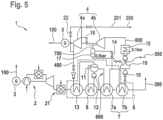
- the power plant 1 is a gas and steam power plant with combined heat and power generation and includes a gas turbine 2 and a steam turbine 4.
- the gas turbine 2 is used to drive a first generator 3, through which electrical energy 100 can be output.
- the steam turbine 4 is used to drive a second generator 5, through which electrical energy 100 can also be output.
- the operation of the gas turbine 2 generates flue gas 300 which is cooled in a heat recovery steam generator 6 in order to to be able to use waste heat from the flue gas 300 .
- an additional firing system 21 can be present between the gas turbine 2 and the heat recovery steam generator 6 in order to additionally heat the flue gas 300 .
- the heat recovery steam generator 6 comprises a preheater 7, an evaporator 8 and a superheater 13, which are provided for heat exchange.
- fresh water 500 is supplied externally or is obtained from condensed steam of the power plant 1 via a deaerator 19 .
- the fresh water 500 is conveyed through the preheater 7 by a feed water pumping device 10 and compressed, as a result of which feed water 600 is provided under a feed water pressure.
- the feed water 600 is transferred to a steam drum 11 . in the in 1 example shown, the feed water pressure is 100 bar.
- the feed water 600 is conveyed from the steam drum 11 through the evaporator 8 via a feed pump 12 . This leads to the evaporator 8 at least partially evaporating the feed water 600 , live steam 400 generated in this way being fed back to the steam drum 11 .
- the live steam 400 is separated from the feed water 600 in the steam drum 11 .
- the live steam 400 is superheated by the superheater 13 and then fed to the steam turbine 4 .
- the steam turbine 4 extracts energy from the live steam 400 and uses this energy to drive the second generator 5 so that residual steam 201 is output at an outlet of the steam turbine 4 .
- the residual steam 201 has a residual steam pressure in the in 1 embodiment shown is 5 bar and is therefore in particular lower than a live steam pressure of, for example, 95 bar.
- a high-pressure bypass 22 can also be present. This means that the steam turbine 4 is bypassed via an alternative bypass path with a throttle and in particular also injection cooling by means of hot water injection (not shown) in order to generate a larger amount of residual steam 201 .
- the fresh water 500 is first preheated in the preheater 7 in order to obtain the feed water 600, then the feed water 600 is evaporated to form live steam 400 in the evaporator 8 and finally the live steam 400 is superheated in the superheater 13.
- the superheater 13 is arranged at the hottest point of a flow of the flue gas 300, the evaporator 8 behind the superheater 13 and the preheater 7 behind the evaporator 8 and thus at a coldest point of the flow of the flue gas 300.
- an additional steam throttle valve 9 is present.
- the additional steam throttle valve 9 is arranged between the steam drum 11 and the preheater 7 and is used to remove feed water 600.
- the feed water 600 is in the additional steam throttle valve 9 to the residual steam pressure, ie in the in 1 shown embodiment to 5 bar, relaxed and fed to an additional steam separation tank 16.
- the additional steam separating tank 16 is used to separate residual water from the additional steam 202, the additional steam 202 being mixed with the residual steam 201 in order to produce the process steam 200, which can be extracted from the power plant 1.
- Such mixing is possible without any problems, since the additional steam 202 has the same pressure as the residual steam 201 due to the additional steam throttle valve 9.
- the residual water that was separated in the additional steam separation tank 16 is fed in particular to the deaerator 19 so that it can be used again as feed water 600.
- the residual steam 201 is condensed in whole or in part in a condenser 15 .
- a bypass 18 is provided for this purpose, through which the outlet of the steam turbine 4 is connected to the condenser 15 .
- the condensed original residual steam 201 is transferred from the condenser 15 to the deaerator 19.
- the additional steam throttle valve 9 is in particular controllable.
- a withdrawal of feed water 600 can thus be regulated, with the result, in particular, that a flow rate through the preheater 7 can also be regulated.
- a flow through the preheater 7 can thus be adjusted in such a way that on the one hand the mass flow through the evaporator 8 is not influenced and at the same time the flue gas 300 is optimally cooled.
- the flue gas 300 is cooled to a low residual temperature above a sulfuric acid dew point, for example to a residual temperature of 90°C.
- the electrical efficiency of the power plant 1 can be compared be increased in a conventional power plant without an additional steam throttle valve 9 in that the process steam 200 is provided completely by the additional steam 202 and thus via the additional steam throttle valve 9 . There is therefore no output of residual steam 201 as process steam.
- the entire residual steam 201 can thus be routed via the bypass 18 into the condenser 15 and thus have a significantly lower pressure than the process steam pressure, as a result of which the power output of the steam turbine 4 is increased.
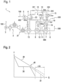
- FIG. 12 schematically shows a QT diagram of the process taking place in the power plant 1 according to the first exemplary embodiment.
- the ordinate shows the temperature value T of the flue gas 300 and the abscissa the amount of heat Q removed from the flue gas 300.
- a maximum energy 20 of the flue gas 300 is shown as a linear curve.
- the profile 30 shows the amount of heat removed according to the process of the power plant 1.
- the advantage of the additional removal of feed water 600 at the additional steam throttle valve 9 is shown as an alternative profile 31 with dashed lines.
- the pinch point 40 is characteristic of QT diagrams. At this point, the curve 30 has the smallest distance to the maximum energy 20, this distance being designed to be approximately 10° C. in particular. It is in 2 also shown that the influence of the removal of the feed water 600, which is represented by the dashed alternative course 31, has effects only on the temperature range below the pinch point 40. The generation of live steam 400, for which the temperature range above the pinch point 40 is mainly relevant, thus remains unaffected by the additional measure. However, it can be seen that compared to the course 30 without additional removal of the feed water 600 at the additional-steam throttle valve 9, a higher quantity of energy ⁇ Q is removed from the flue gas 300 can. A larger proportion of the energy of the flue gas 300 is thus used than in the prior art, as a result of which the efficiency of the power plant 1 is increased compared to the prior art.
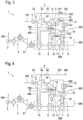
- the second exemplary embodiment is essentially identical to the first exemplary embodiment, with the difference in the first exemplary embodiment being that the steam turbine 4 is designed in two stages. It is therefore provided that the first stage 4a, in particular the high-pressure stage, is operated with the live steam 400, as was described in the first exemplary embodiment.
- the residual steam 201 generated in this way can in turn be mixed with the additional steam 202 in order to provide the process steam 200 .
- the second stage 4b of the steam turbine 4, in particular the low-pressure stage, is operated by a drive steam 700.
- the drive steam 700 is produced by expanding the residual water that was separated from the additional steam 202 in the additional steam separating tank 16 .
- Said residual water is expanded by a drive steam throttle valve 14 to the drive steam pressure, which is lower than the residual steam pressure. in the in 3 shown embodiment, this drive steam pressure is 0.5 bar.
- the drive steam 700 is fed to a drive steam separation tank 17, as a result of which residual water can be separated from the drive steam 700 again.
- the residual water from the drive steam separation tank 17 is returned and can run through the preheater 7 again.
- the residual water can be fed to the deaerator 19 . This takes place in particular when the pressure is still greater than 1 bar, otherwise the residual water will preferably be fed into the condenser 15 since the deaerator 19 is advantageously operated at a pressure of approximately 1 bar (absolute).
- bypass 18 does not connect the outlet of the first stage 4a of the steam turbine 4 to the condenser 15, but to the inlet of the second stage 4b of the steam turbine 4. If the residual steam 201 is not required as process steam 200, it can be fed to the second stage 4b of the steam turbine 4.
- the second stage 4b of the steam turbine 4 converts the supplied steam, in particular the working steam 700, into waste steam 800, which is no longer used and is fed directly to the condenser 15.
- a two-stage steam turbine 4 is thus used in the second exemplary embodiment.
- the basic principle of removing feed water 600 remains the same as in the first exemplary embodiment.
- the additional steam 202 has a higher pressure level than is necessary for the operation of the second stage 4b, the working steam 700 can thus be generated easily without the residual steam 201 of the first stage 4a having to be used for this purpose.
- the residual water from the additional steam 202 before the recirculation is used to drive the second stage 4b of the steam turbine 4 as in the first exemplary embodiment.
- FIG. 4 shows another embodiment of the invention.
- the power plant 1 according to a third embodiment, as in 4 shown is almost identical to the power plant 1 according to the second embodiment of the invention.
- the drive steam 700 is not generated from the residual water of the additional steam 202, as in the second embodiment, but directly from the feed water 600.
- the drive steam throttle valve 14 with a feed water line is used for this purpose coupled between the preheater 7 and the steam drum 11. Feedwater 600 is thus removed through the drive steam throttle valve 14 and converted to drive steam 700 by expansion to the drive steam pressure.
- the drive steam separation tank 17 is present, through which the residual water can be separated from the drive steam 700 . Furthermore, the residual water is returned to an input of the preheater 7.
- the generation of additional steam 202 is omitted.
- the process steam 200 is thus formed solely by the residual steam 201 . Since the residual steam 201 does not have to be used to drive the second stage 4b of the steam turbine 4, since this is taken over by the drive steam 700, the amount of process steam 200 is again maximized compared to the prior art.
- the third exemplary embodiment thus also has the same advantages as the previous exemplary embodiments.
- the fourth exemplary embodiment is almost identical to the third exemplary embodiment, the only difference being the preheater 7 .
- the preheater 7 according to the fourth embodiment has a first preheating area 7a and a second preheating area 7b.
- the first preheating area 7a and the second preheating area 7b are connected in series, with the tapping of the feed water 600 taking place between the first preheating area 7a and the second preheating area 7b, in which the feed water 600 is expanded through the drive steam throttle valve 14 to form the drive steam 700.
- the first preheating area 7a and the second preheating area 7b can be configured identically, so that feed water 600 is branched off exactly in the middle of the preheater 7 .
- the first preheating area 7a can be configured differently from the second preheating area 7b in order to branch off the feed water 600 at any point of the preheater 7 and expand it through the drive steam throttle valve 14 .
- the fourth exemplary embodiment shown can also be combined with the first exemplary embodiment or the second exemplary embodiment.
- the preheater 7 can also be divided into the first preheating area 7a and the second preheating area 7b in the first exemplary embodiment or second exemplary embodiment, with the feed water 600 being removed through the additional steam throttle valve 9 between the first preheating area 7a and the second preheating area 7b.
- the concept according to the invention can also be applied to steam turbines 4 with more than two stages.
- the lower stages can be operated with steam which was obtained by removing and expanding feed water 600 at any point in the preheater 7 or between the preheater 7 and the steam drum 11 .
Landscapes
- Engineering & Computer Science (AREA)
- Chemical & Material Sciences (AREA)
- Combustion & Propulsion (AREA)
- Mechanical Engineering (AREA)
- General Engineering & Computer Science (AREA)
- Physics & Mathematics (AREA)
- Thermal Sciences (AREA)
- Engine Equipment That Uses Special Cycles (AREA)
Priority Applications (1)
| Application Number | Priority Date | Filing Date | Title |
|---|---|---|---|
| HRP20230973TT HRP20230973T1 (hr) | 2017-12-22 | 2018-12-12 | Elektrana |
Applications Claiming Priority (2)
| Application Number | Priority Date | Filing Date | Title |
|---|---|---|---|
| DE102017223705.8A DE102017223705A1 (de) | 2017-12-22 | 2017-12-22 | Kraftwerk |
| PCT/EP2018/084460 WO2019121191A1 (de) | 2017-12-22 | 2018-12-12 | Kraftwerk |
Publications (3)
| Publication Number | Publication Date |
|---|---|
| EP3728800A1 EP3728800A1 (de) | 2020-10-28 |
| EP3728800B1 true EP3728800B1 (de) | 2023-07-26 |
| EP3728800C0 EP3728800C0 (de) | 2023-07-26 |
Family
ID=64901494
Family Applications (1)
| Application Number | Title | Priority Date | Filing Date |
|---|---|---|---|
| EP18826986.4A Active EP3728800B1 (de) | 2017-12-22 | 2018-12-12 | Kraftwerk |
Country Status (9)
| Country | Link |
|---|---|
| US (1) | US11339687B2 (hu) |
| EP (1) | EP3728800B1 (hu) |
| CA (1) | CA3088697A1 (hu) |
| DE (1) | DE102017223705A1 (hu) |
| ES (1) | ES2959983T3 (hu) |
| HR (1) | HRP20230973T1 (hu) |
| HU (1) | HUE063261T2 (hu) |
| PL (1) | PL3728800T3 (hu) |
| WO (1) | WO2019121191A1 (hu) |
Families Citing this family (1)
| Publication number | Priority date | Publication date | Assignee | Title |
|---|---|---|---|---|
| DE102020000614B4 (de) | 2020-01-30 | 2024-04-25 | EEO Tech Operations GmbH | Energiemanagementsystem für Restwärme (ESR) |
Family Cites Families (13)
| Publication number | Priority date | Publication date | Assignee | Title |
|---|---|---|---|---|
| DE712163C (de) * | 1937-01-26 | 1941-10-14 | Fr Des Regulateurs Universels | Vorrichtung zum gleichzeitigen Kuehlen und Entspannen von ueberhitztem Dampf |
| US4099374A (en) * | 1976-04-15 | 1978-07-11 | Westinghouse Electric Corp. | Gasifier-combined cycle plant |
| CH633610A5 (de) * | 1978-05-19 | 1982-12-15 | Bbc Brown Boveri & Cie | Kombiniertes gas/dampfturbinenkraftwerk mit gegendruckturbine, insbesondere fuer industriezwecke. |
| NL8701573A (nl) | 1987-07-03 | 1989-02-01 | Prometheus Energy Systems | Werkwijze en inrichting voor het opwekken van elektrische en/of mechanische energie uit tenminste een laagwaardige brandstof. |
| DE3804605A1 (de) | 1988-02-12 | 1989-08-24 | Siemens Ag | Verfahren und anlage zur abhitzedampferzeugung |
| DE59000787D1 (de) * | 1989-07-27 | 1993-03-04 | Siemens Ag | Abhitzedampferzeuger fuer ein gas- und dampfturbinenkraftwerk. |
| DE59205446D1 (de) | 1991-07-17 | 1996-04-04 | Siemens Ag | Verfahren zum Betreiben einer Gas- und Dampfturbinenanlage und Anlage zur Durchführung des Verfahrens |
| DE4409811C1 (de) | 1994-03-22 | 1995-05-18 | Siemens Ag | Verfahren zum Betreiben eines Abhitzedampferzeugers sowie danach arbeitender Abhitzedampferzeuger |
| US6167692B1 (en) * | 1998-06-29 | 2001-01-02 | General Electric Co. | Method of using fuel gas expander in power generating plants |
| DE19944920B4 (de) * | 1999-09-20 | 2013-11-21 | Alstom Technology Ltd. | Kombikraftwerk mit Einspritzvorrichtung zum Einspritzen von Wasser in den Frischdampf |
| US7107774B2 (en) * | 2003-08-12 | 2006-09-19 | Washington Group International, Inc. | Method and apparatus for combined cycle power plant operation |
| EP2256316A1 (de) * | 2009-05-28 | 2010-12-01 | Siemens Aktiengesellschaft | Ansauglufttemperiereinrichtung sowie ein Verfahren zum Betrieb einer Ansauglufttemperiereinrichtung |
| JP5774381B2 (ja) * | 2011-05-31 | 2015-09-09 | 株式会社東芝 | 排熱回収ボイラおよび発電プラント |
-
2017
- 2017-12-22 DE DE102017223705.8A patent/DE102017223705A1/de active Pending
-
2018
- 2018-12-12 ES ES18826986T patent/ES2959983T3/es active Active
- 2018-12-12 HU HUE18826986A patent/HUE063261T2/hu unknown
- 2018-12-12 CA CA3088697A patent/CA3088697A1/en active Pending
- 2018-12-12 WO PCT/EP2018/084460 patent/WO2019121191A1/de unknown
- 2018-12-12 US US16/956,986 patent/US11339687B2/en active Active
- 2018-12-12 EP EP18826986.4A patent/EP3728800B1/de active Active
- 2018-12-12 HR HRP20230973TT patent/HRP20230973T1/hr unknown
- 2018-12-12 PL PL18826986.4T patent/PL3728800T3/pl unknown
Also Published As
| Publication number | Publication date |
|---|---|
| WO2019121191A1 (de) | 2019-06-27 |
| US20200392874A1 (en) | 2020-12-17 |
| EP3728800A1 (de) | 2020-10-28 |
| ES2959983T3 (es) | 2024-02-29 |
| US11339687B2 (en) | 2022-05-24 |
| HRP20230973T1 (hr) | 2023-12-08 |
| HUE063261T2 (hu) | 2024-01-28 |
| PL3728800T3 (pl) | 2024-01-15 |
| CA3088697A1 (en) | 2019-06-27 |
| EP3728800C0 (de) | 2023-07-26 |
| DE102017223705A1 (de) | 2019-06-27 |
Similar Documents
| Publication | Publication Date | Title |
|---|---|---|
| DE68926220T2 (de) | Verfahren und Vorrichtung zur Dampfkrafterzeugung | |
| DE10041413B4 (de) | Verfahren zum Betrieb einer Kraftwerksanlage | |
| EP2368021B1 (de) | Abhitzedampferzeuger sowie ein verfahren zum verbesserten betrieb eines abhitzedampferzeugers | |
| EP0674099A1 (de) | Verfahren zur Kühlung von thermische belasteten Komponenten einer Gasturbogruppe | |
| EP0778397A2 (de) | Verfahren zum Betrieb einer mit einem Abhitzedampferzeuger und einem Dampfverbraucher kombinierten Dampfturbogruppe | |
| CH702163A2 (de) | Verfahren zur Steigerung der Leistungsabgabe eines Gas- und Dampf-Kombikraftwerks während ausgewählter Betriebszeiträume. | |
| WO2008067855A2 (de) | Verfahren und vorrichtung zur erhöhung von leistung und wirkungsgrad eines orc-kraftwerkprozesses | |
| WO2016131920A1 (de) | Dampfkraftwerk und verfahren zu dessen betrieb | |
| EP1154127B1 (de) | Verfahren zum Betrieb eines Kombikraftwerkes sowie Kombikraftwerk zur Durchführung des Verfahrens | |
| EP1870646B1 (de) | Verfahren und Vorrichtung zur Rückgewinnung von Kondensationswärme aus einem thermodynamischen Kreisprozess | |
| WO2005056994A1 (de) | Luftspeicherkraftanlage | |
| EP3728800B1 (de) | Kraftwerk | |
| EP3469190B1 (de) | Kraftwerk mit wärmespeicher | |
| DE19720789B4 (de) | Verfahren und Vorrichtung zur Erzeugung von Dampf | |
| DE102012110579B4 (de) | Anlage und Verfahren zur Erzeugung von Prozessdampf | |
| WO2007144285A2 (de) | Dampfkraftanlage | |
| EP3810907A1 (de) | Abgasrezirkulation in gas- und dampfturbinenanlagen | |
| DE19944920B4 (de) | Kombikraftwerk mit Einspritzvorrichtung zum Einspritzen von Wasser in den Frischdampf | |
| WO2013185909A1 (de) | Verfahren zum betreiben eines kraftwerks sowie kraftwerk | |
| EP2559867A1 (de) | Verfahren zum Erzeugen von elektrischer Energie mittels eines Kombikraftwerkes sowie Kombikraftwerk zur Durchführung des Verfahrens | |
| EP2385223A1 (de) | Verfahren zur Steigerung des Wirkungsgrades von Gas- und Dampfturbinenanlagen | |
| EP2138677B1 (de) | Gas- und Dampfturbinenanlage | |
| WO2013060447A1 (de) | Abwärmenutzungsvorrichtung | |
| DE10124492B4 (de) | Verfahren zum Betrieb eines Kombikraftwerkes bei unterschiedlichen Netzanforderungen | |
| DE102015118098A1 (de) | Verfahren zur Speisewasservorwärmung eines Dampferzeugers eines Kraftwerks |
Legal Events
| Date | Code | Title | Description |
|---|---|---|---|
| REG | Reference to a national code |
Ref country code: HR Ref legal event code: TUEP Ref document number: P20230973T Country of ref document: HR |
|
| STAA | Information on the status of an ep patent application or granted ep patent |
Free format text: STATUS: UNKNOWN |
|
| STAA | Information on the status of an ep patent application or granted ep patent |
Free format text: STATUS: THE INTERNATIONAL PUBLICATION HAS BEEN MADE |
|
| PUAI | Public reference made under article 153(3) epc to a published international application that has entered the european phase |
Free format text: ORIGINAL CODE: 0009012 |
|
| STAA | Information on the status of an ep patent application or granted ep patent |
Free format text: STATUS: REQUEST FOR EXAMINATION WAS MADE |
|
| 17P | Request for examination filed |
Effective date: 20200721 |
|
| AK | Designated contracting states |
Kind code of ref document: A1 Designated state(s): AL AT BE BG CH CY CZ DE DK EE ES FI FR GB GR HR HU IE IS IT LI LT LU LV MC MK MT NL NO PL PT RO RS SE SI SK SM TR |
|
| AX | Request for extension of the european patent |
Extension state: BA ME |
|
| DAV | Request for validation of the european patent (deleted) | ||
| DAX | Request for extension of the european patent (deleted) | ||
| GRAP | Despatch of communication of intention to grant a patent |
Free format text: ORIGINAL CODE: EPIDOSNIGR1 |
|
| STAA | Information on the status of an ep patent application or granted ep patent |
Free format text: STATUS: GRANT OF PATENT IS INTENDED |
|
| RIC1 | Information provided on ipc code assigned before grant |
Ipc: F01K 7/34 20060101ALI20221014BHEP Ipc: F22D 5/00 20060101ALI20221014BHEP Ipc: F01K 23/10 20060101ALI20221014BHEP Ipc: F01K 17/04 20060101AFI20221014BHEP |
|
| INTG | Intention to grant announced |
Effective date: 20221123 |
|
| GRAJ | Information related to disapproval of communication of intention to grant by the applicant or resumption of examination proceedings by the epo deleted |
Free format text: ORIGINAL CODE: EPIDOSDIGR1 |
|
| STAA | Information on the status of an ep patent application or granted ep patent |
Free format text: STATUS: REQUEST FOR EXAMINATION WAS MADE |
|
| INTC | Intention to grant announced (deleted) | ||
| GRAP | Despatch of communication of intention to grant a patent |
Free format text: ORIGINAL CODE: EPIDOSNIGR1 |
|
| STAA | Information on the status of an ep patent application or granted ep patent |
Free format text: STATUS: GRANT OF PATENT IS INTENDED |
|
| INTG | Intention to grant announced |
Effective date: 20230508 |
|
| GRAS | Grant fee paid |
Free format text: ORIGINAL CODE: EPIDOSNIGR3 |
|
| GRAA | (expected) grant |
Free format text: ORIGINAL CODE: 0009210 |
|
| STAA | Information on the status of an ep patent application or granted ep patent |
Free format text: STATUS: THE PATENT HAS BEEN GRANTED |
|
| AK | Designated contracting states |
Kind code of ref document: B1 Designated state(s): AL AT BE BG CH CY CZ DE DK EE ES FI FR GB GR HR HU IE IS IT LI LT LU LV MC MK MT NL NO PL PT RO RS SE SI SK SM TR |
|
| REG | Reference to a national code |
Ref country code: CH Ref legal event code: EP |
|
| REG | Reference to a national code |
Ref country code: DE Ref legal event code: R096 Ref document number: 502018012814 Country of ref document: DE |
|
| REG | Reference to a national code |
Ref country code: IE Ref legal event code: FG4D Free format text: LANGUAGE OF EP DOCUMENT: GERMAN |
|
| U01 | Request for unitary effect filed |
Effective date: 20230817 |
|
| U07 | Unitary effect registered |
Designated state(s): AT BE BG DE DK EE FI FR IT LT LU LV MT NL PT SE SI Effective date: 20230823 |
|
| REG | Reference to a national code |
Ref country code: RO Ref legal event code: EPE |
|
| REG | Reference to a national code |
Ref country code: LT Ref legal event code: MG9D |
|
| REG | Reference to a national code |
Ref country code: HR Ref legal event code: T1PR Ref document number: P20230973 Country of ref document: HR |
|
| REG | Reference to a national code |
Ref country code: HR Ref legal event code: ODRP Ref document number: P20230973 Country of ref document: HR Payment date: 20231204 Year of fee payment: 6 |
|
| U20 | Renewal fee paid [unitary effect] |
Year of fee payment: 6 Effective date: 20231214 |
|
| PG25 | Lapsed in a contracting state [announced via postgrant information from national office to epo] |
Ref country code: GR Free format text: LAPSE BECAUSE OF FAILURE TO SUBMIT A TRANSLATION OF THE DESCRIPTION OR TO PAY THE FEE WITHIN THE PRESCRIBED TIME-LIMIT Effective date: 20231027 |
|
| PGFP | Annual fee paid to national office [announced via postgrant information from national office to epo] |
Ref country code: GB Payment date: 20231220 Year of fee payment: 6 |
|
| PG25 | Lapsed in a contracting state [announced via postgrant information from national office to epo] |
Ref country code: IS Free format text: LAPSE BECAUSE OF FAILURE TO SUBMIT A TRANSLATION OF THE DESCRIPTION OR TO PAY THE FEE WITHIN THE PRESCRIBED TIME-LIMIT Effective date: 20231126 |
|
| REG | Reference to a national code |
Ref country code: HU Ref legal event code: AG4A Ref document number: E063261 Country of ref document: HU |
|
| PG25 | Lapsed in a contracting state [announced via postgrant information from national office to epo] |
Ref country code: RS Free format text: LAPSE BECAUSE OF FAILURE TO SUBMIT A TRANSLATION OF THE DESCRIPTION OR TO PAY THE FEE WITHIN THE PRESCRIBED TIME-LIMIT Effective date: 20230726 Ref country code: NO Free format text: LAPSE BECAUSE OF FAILURE TO SUBMIT A TRANSLATION OF THE DESCRIPTION OR TO PAY THE FEE WITHIN THE PRESCRIBED TIME-LIMIT Effective date: 20231026 Ref country code: IS Free format text: LAPSE BECAUSE OF FAILURE TO SUBMIT A TRANSLATION OF THE DESCRIPTION OR TO PAY THE FEE WITHIN THE PRESCRIBED TIME-LIMIT Effective date: 20231126 Ref country code: GR Free format text: LAPSE BECAUSE OF FAILURE TO SUBMIT A TRANSLATION OF THE DESCRIPTION OR TO PAY THE FEE WITHIN THE PRESCRIBED TIME-LIMIT Effective date: 20231027 |
|
| PGFP | Annual fee paid to national office [announced via postgrant information from national office to epo] |
Ref country code: RO Payment date: 20231206 Year of fee payment: 6 Ref country code: IE Payment date: 20231218 Year of fee payment: 6 Ref country code: HU Payment date: 20231211 Year of fee payment: 6 Ref country code: HR Payment date: 20231204 Year of fee payment: 6 Ref country code: CZ Payment date: 20231130 Year of fee payment: 6 |
|
| PGFP | Annual fee paid to national office [announced via postgrant information from national office to epo] |
Ref country code: PL Payment date: 20231201 Year of fee payment: 6 |
|
| REG | Reference to a national code |
Ref country code: ES Ref legal event code: FG2A Ref document number: 2959983 Country of ref document: ES Kind code of ref document: T3 Effective date: 20240229 |
|
| PGFP | Annual fee paid to national office [announced via postgrant information from national office to epo] |
Ref country code: ES Payment date: 20240118 Year of fee payment: 6 |
|
| REG | Reference to a national code |
Ref country code: DE Ref legal event code: R097 Ref document number: 502018012814 Country of ref document: DE |
|
| PG25 | Lapsed in a contracting state [announced via postgrant information from national office to epo] |
Ref country code: SM Free format text: LAPSE BECAUSE OF FAILURE TO SUBMIT A TRANSLATION OF THE DESCRIPTION OR TO PAY THE FEE WITHIN THE PRESCRIBED TIME-LIMIT Effective date: 20230726 Ref country code: SK Free format text: LAPSE BECAUSE OF FAILURE TO SUBMIT A TRANSLATION OF THE DESCRIPTION OR TO PAY THE FEE WITHIN THE PRESCRIBED TIME-LIMIT Effective date: 20230726 |
|
| PLBE | No opposition filed within time limit |
Free format text: ORIGINAL CODE: 0009261 |
|
| STAA | Information on the status of an ep patent application or granted ep patent |
Free format text: STATUS: NO OPPOSITION FILED WITHIN TIME LIMIT |
|
| 26N | No opposition filed |
Effective date: 20240429 |
|
| REG | Reference to a national code |
Ref country code: CH Ref legal event code: PL |
|
| PG25 | Lapsed in a contracting state [announced via postgrant information from national office to epo] |
Ref country code: MC Free format text: LAPSE BECAUSE OF FAILURE TO SUBMIT A TRANSLATION OF THE DESCRIPTION OR TO PAY THE FEE WITHIN THE PRESCRIBED TIME-LIMIT Effective date: 20230726 |
|
| PG25 | Lapsed in a contracting state [announced via postgrant information from national office to epo] |
Ref country code: MC Free format text: LAPSE BECAUSE OF FAILURE TO SUBMIT A TRANSLATION OF THE DESCRIPTION OR TO PAY THE FEE WITHIN THE PRESCRIBED TIME-LIMIT Effective date: 20230726 |