EP3728792B1 - Ensemble d'arbres pour une turbomachine d'aéronef - Google Patents
Ensemble d'arbres pour une turbomachine d'aéronef Download PDFInfo
- Publication number
- EP3728792B1 EP3728792B1 EP18842432.9A EP18842432A EP3728792B1 EP 3728792 B1 EP3728792 B1 EP 3728792B1 EP 18842432 A EP18842432 A EP 18842432A EP 3728792 B1 EP3728792 B1 EP 3728792B1
- Authority
- EP
- European Patent Office
- Prior art keywords
- teeth
- splines
- shafts
- shaft
- assembly according
- Prior art date
- Legal status (The legal status is an assumption and is not a legal conclusion. Google has not performed a legal analysis and makes no representation as to the accuracy of the status listed.)
- Active
Links
Images



Classifications
-
- F—MECHANICAL ENGINEERING; LIGHTING; HEATING; WEAPONS; BLASTING
- F16—ENGINEERING ELEMENTS AND UNITS; GENERAL MEASURES FOR PRODUCING AND MAINTAINING EFFECTIVE FUNCTIONING OF MACHINES OR INSTALLATIONS; THERMAL INSULATION IN GENERAL
- F16D—COUPLINGS FOR TRANSMITTING ROTATION; CLUTCHES; BRAKES
- F16D1/00—Couplings for rigidly connecting two coaxial shafts or other movable machine elements
- F16D1/10—Quick-acting couplings in which the parts are connected by simply bringing them together axially
- F16D1/101—Quick-acting couplings in which the parts are connected by simply bringing them together axially without axial retaining means rotating with the coupling
-
- F—MECHANICAL ENGINEERING; LIGHTING; HEATING; WEAPONS; BLASTING
- F01—MACHINES OR ENGINES IN GENERAL; ENGINE PLANTS IN GENERAL; STEAM ENGINES
- F01D—NON-POSITIVE DISPLACEMENT MACHINES OR ENGINES, e.g. STEAM TURBINES
- F01D5/00—Blades; Blade-carrying members; Heating, heat-insulating, cooling or antivibration means on the blades or the members
- F01D5/02—Blade-carrying members, e.g. rotors
- F01D5/026—Shaft to shaft connections
-
- F—MECHANICAL ENGINEERING; LIGHTING; HEATING; WEAPONS; BLASTING
- F02—COMBUSTION ENGINES; HOT-GAS OR COMBUSTION-PRODUCT ENGINE PLANTS
- F02C—GAS-TURBINE PLANTS; AIR INTAKES FOR JET-PROPULSION PLANTS; CONTROLLING FUEL SUPPLY IN AIR-BREATHING JET-PROPULSION PLANTS
- F02C7/00—Features, components parts, details or accessories, not provided for in, or of interest apart form groups F02C1/00 - F02C6/00; Air intakes for jet-propulsion plants
- F02C7/36—Power transmission arrangements between the different shafts of the gas turbine plant, or between the gas-turbine plant and the power user
-
- F—MECHANICAL ENGINEERING; LIGHTING; HEATING; WEAPONS; BLASTING
- F02—COMBUSTION ENGINES; HOT-GAS OR COMBUSTION-PRODUCT ENGINE PLANTS
- F02C—GAS-TURBINE PLANTS; AIR INTAKES FOR JET-PROPULSION PLANTS; CONTROLLING FUEL SUPPLY IN AIR-BREATHING JET-PROPULSION PLANTS
- F02C3/00—Gas-turbine plants characterised by the use of combustion products as the working fluid
- F02C3/04—Gas-turbine plants characterised by the use of combustion products as the working fluid having a turbine driving a compressor
- F02C3/107—Gas-turbine plants characterised by the use of combustion products as the working fluid having a turbine driving a compressor with two or more rotors connected by power transmission
-
- F—MECHANICAL ENGINEERING; LIGHTING; HEATING; WEAPONS; BLASTING
- F02—COMBUSTION ENGINES; HOT-GAS OR COMBUSTION-PRODUCT ENGINE PLANTS
- F02K—JET-PROPULSION PLANTS
- F02K3/00—Plants including a gas turbine driving a compressor or a ducted fan
- F02K3/02—Plants including a gas turbine driving a compressor or a ducted fan in which part of the working fluid by-passes the turbine and combustion chamber
- F02K3/04—Plants including a gas turbine driving a compressor or a ducted fan in which part of the working fluid by-passes the turbine and combustion chamber the plant including ducted fans, i.e. fans with high volume, low pressure outputs, for augmenting the jet thrust, e.g. of double-flow type
- F02K3/06—Plants including a gas turbine driving a compressor or a ducted fan in which part of the working fluid by-passes the turbine and combustion chamber the plant including ducted fans, i.e. fans with high volume, low pressure outputs, for augmenting the jet thrust, e.g. of double-flow type with front fan
-
- F—MECHANICAL ENGINEERING; LIGHTING; HEATING; WEAPONS; BLASTING
- F05—INDEXING SCHEMES RELATING TO ENGINES OR PUMPS IN VARIOUS SUBCLASSES OF CLASSES F01-F04
- F05D—INDEXING SCHEME FOR ASPECTS RELATING TO NON-POSITIVE-DISPLACEMENT MACHINES OR ENGINES, GAS-TURBINES OR JET-PROPULSION PLANTS
- F05D2260/00—Function
- F05D2260/40—Transmission of power
- F05D2260/403—Transmission of power through the shape of the drive components
- F05D2260/4031—Transmission of power through the shape of the drive components as in toothed gearing
-
- F—MECHANICAL ENGINEERING; LIGHTING; HEATING; WEAPONS; BLASTING
- F05—INDEXING SCHEMES RELATING TO ENGINES OR PUMPS IN VARIOUS SUBCLASSES OF CLASSES F01-F04
- F05D—INDEXING SCHEME FOR ASPECTS RELATING TO NON-POSITIVE-DISPLACEMENT MACHINES OR ENGINES, GAS-TURBINES OR JET-PROPULSION PLANTS
- F05D2260/00—Function
- F05D2260/40—Transmission of power
- F05D2260/403—Transmission of power through the shape of the drive components
- F05D2260/4031—Transmission of power through the shape of the drive components as in toothed gearing
- F05D2260/40311—Transmission of power through the shape of the drive components as in toothed gearing of the epicyclical, planetary or differential type
-
- F—MECHANICAL ENGINEERING; LIGHTING; HEATING; WEAPONS; BLASTING
- F16—ENGINEERING ELEMENTS AND UNITS; GENERAL MEASURES FOR PRODUCING AND MAINTAINING EFFECTIVE FUNCTIONING OF MACHINES OR INSTALLATIONS; THERMAL INSULATION IN GENERAL
- F16D—COUPLINGS FOR TRANSMITTING ROTATION; CLUTCHES; BRAKES
- F16D1/00—Couplings for rigidly connecting two coaxial shafts or other movable machine elements
- F16D1/10—Quick-acting couplings in which the parts are connected by simply bringing them together axially
- F16D2001/103—Quick-acting couplings in which the parts are connected by simply bringing them together axially the torque is transmitted via splined connections
-
- Y—GENERAL TAGGING OF NEW TECHNOLOGICAL DEVELOPMENTS; GENERAL TAGGING OF CROSS-SECTIONAL TECHNOLOGIES SPANNING OVER SEVERAL SECTIONS OF THE IPC; TECHNICAL SUBJECTS COVERED BY FORMER USPC CROSS-REFERENCE ART COLLECTIONS [XRACs] AND DIGESTS
- Y02—TECHNOLOGIES OR APPLICATIONS FOR MITIGATION OR ADAPTATION AGAINST CLIMATE CHANGE
- Y02T—CLIMATE CHANGE MITIGATION TECHNOLOGIES RELATED TO TRANSPORTATION
- Y02T50/00—Aeronautics or air transport
- Y02T50/60—Efficient propulsion technologies, e.g. for aircraft
Definitions
- the present invention relates to a set of shafts for an aircraft turbomachine.
- the state of the art includes in particular the documents EP-A1-1 927 774 , US-A1-2015 / 323014 and FR-A1-2 918 726 .
- a turbomachine comprises a gas generator and a fan located at one end of the gas generator and surrounded by a fan casing.
- the blower is intended to generate an air flow, one part of which feeds the gas generator and forms a primary flow, and another part flows between the gas generator and the blower housing and forms a secondary air flow which generates a major part of the thrust of the turbomachine.
- the gas generator comprises, from upstream to downstream in the direction of the gas flow, at least one compressor, a combustion chamber and at least one turbine.
- the role of the compressor is to increase the pressure of the air supplied to the combustion chamber.
- the role of the turbine is to drive the compressor in rotation by taking part of the pressure energy of the hot gases leaving the combustion chamber and transforming it into mechanical energy.
- the compressor and the turbine consist of a first set of fixed parts constituting the stator and a second set of parts, capable of being rotated relative to the stator, constituting the rotor.
- the rotor of the compressor and the rotor of the turbine form an assembly integrally connected by a rotating shaft.
- the rotation of the rotor relative to the stator is made possible by means of bearings, a bearing being a mechanical member supporting and guiding a rotor, in particular the shaft of this rotor.
- This bearing comprises a first part fixed to the rotor shaft and a second part fixed to the stator by means of a support of landing.
- a bearing is arranged between the two parts of the bearing thus allowing the rotation of one part of the bearing relative to the other.
- the bearing may for example be of the ball, cylindrical roller or tapered roller type.
- a turbomachine can also be of the “double-barrel” type, which means that it comprises two rotors arranged coaxially.
- a first body is called a low pressure body and a second body is called a high pressure body.
- the gas generator comprises in this case, from upstream to downstream, a low pressure compressor, a high pressure compressor, the combustion chamber, a high pressure turbine and a low pressure turbine.
- the low pressure turbine shaft drives the fan shaft via a reduction gear which is lubricated and housed in an upstream lubrication chamber.
- the fan shaft will rotate in the same direction or in the opposite direction to the turbine shaft, and the fan shaft will rotate at a slower speed than that of the turbine shaft.
- modules of a turbomachine are generally sets of parts which are attached to one another.
- the modules perform the various functions of the turbomachine: compressor, turbine, combustion chamber, equipment, etc.
- the turbomachine comprises an upstream module comprising the fan shaft, bearing supports and the reduction gear.
- This upstream module is assembled on the low pressure compressor to form a low pressure module of the turbomachine, the module comprising in particular a line of shafts comprising the input shaft of the reducer which must mesh with the solar of the reducer.
- the sun gear of the reducer forms a shaft or a portion of a shaft which is intended to be coupled to this input shaft by a male / female engagement with splines.
- the solar forms a female shaft with internal splines and the input shaft forms a male shaft with external splines.
- the splines of the shafts are rectilinear and extend along the longitudinal axis of the turbomachine, so that the shafts are engaged one in the other by axial translation of the shafts towards one another.
- the aforementioned upstream module is relatively heavy due in particular to the mass of the reducer which can reach 200 kg or even more.
- the reducer In the case of a horizontal assembly, the reducer is cantilevered at the end of the fan shaft and even if this shaft is indeed concentric with the input shaft, the reducer, because of its mass, slightly deforms the fan shaft, which risks causing misalignment of the reducer and its input shaft. This phenomenon can be accentuated or generated by the radial clearances between the meshing teeth in the reduction gear.
- these contact areas are not easily controllable. There is therefore a risk of damaging the splines and of not being able to check their condition after assembly.
- the present invention provides an improvement to this technology, which is simple, efficient and economical, and makes it possible to guarantee optimal positioning of the splines of the shafts during their insertion.
- the teeth are provided and designed to ensure the centering of the shafts during their assembly but also to preferentially undergo shocks and stresses during assembly. If shocks occur between the shafts during assembly, they will be located at the level of the teeth which will eventually be damaged. However, this will not affect the health of the shafts or that of the splines because these teeth are not intended to transmit torque between the shafts. Their function, centering, is only used during insert mounting of the shafts, and disappears once the shafts are in the mating position.
- the present invention also relates to an aircraft turbomachine, comprising at least one assembly as described above.
- the first and second shafts are a reducer solar and a low pressure shaft or two low pressure shafts.
- a turbomachine 1 with reduction gear which comprises, conventionally, a fan S, a low pressure compressor 1a, a high pressure compressor 1b, a combustion chamber 1c, a high pressure turbine 1d and a low pressure turbine 1e.
- the rotors of the high pressure compressor 1b and of the high pressure turbine 1d are connected by a high pressure shaft 5 and form with it a high pressure body (HP).
- the rotors of the low pressure compressor 1a and the low pressure turbine 1e are connected by a shaft low pressure 4 and form with it a low pressure body (LP).
- the fan is, for its part, carried by a fan shaft 3 which is connected by a reduction gear 7 to the LP shaft 4.
- the HP and LP shafts extend along an axis which is the axis of rotation of the turbomachine 1.
- axis which is the axis of rotation of the turbomachine 1.
- the notions of longitudinal or radial, and of interior or exterior, relate to this axis.
- the turbomachine 1 comprises structural housings.
- the HP body is held by two structural casings: the inter-compressor casing and the inter-turbine casing
- the LP body is held by at least two structural casings: the intermediate casing 2 and the inter-turbine casing and / or the casing exhaust 6.
- the intermediate casing 2 supports the bearings of the LP turbine shaft 4 which are housed in a front or upstream enclosure denoted E1.
- the exhaust casing 6 supports the bearings of the LP turbine shaft 4 which are housed in a rear or downstream enclosure denoted E2.
- the enclosures are generally delimited by bearing supports.
- the reducer 7 is here of the epicyclic type.
- the figure 2 very schematically shows the size of the reducer.
- the reducer 7 comprises a solar which is meshed with the satellites and is coupled by means of splines C1, C2 with a shaft 8 which can be considered as the input shaft of the reducer.
- the shaft 8 is driven by the LP shaft 4 via a shaft 9 of the LP compressor which is guided by a downstream bearing 10.
- the shafts 8 and 9 could form a single one-piece shaft.
- Trees 8, 9 and 4 form a line of BP trees.
- the torque at the output of the reducer 7 is transmitted to the fan shaft 3, by a conventional connection, known to those skilled in the art, such as for example a fixing of this fan shaft on the planet carrier forming an output shaft.
- 7a of the reduction gear in the case of an epicyclic reduction gear.
- the fan shaft would be driven by the ring gear.
- the reducer is placed inside the front lubrication enclosure E1.
- the enclosure E1 comprises fixed walls and movable walls.
- the fixed walls of the enclosure E1 comprise an internal wall of the primary flow channel, an upstream bearing support 11 and a downstream bearing support 12.
- the supports 11 and 12 extend towards the inside of the bearing.
- the turbomachine and respectively carry the bearings 13, and the bearing 10. They provide the structure between the housings and the fixed outer rings of the bearings.
- the movable walls of the enclosure E1 comprise the input 8 and output 7a shafts.
- the bearings 10, 13, 14 are housed in the enclosure E1. Seals, not visible in the diagrams, are provided between the fixed and mobile walls and are for example labyrinth seals, brush seals, segmented radial seals, etc.
- the bearings 10, 13 and 14 as well as the reduction gear 7 are lubricated for their correct operation.
- the oil is supplied by suitable means such as nozzles, oil supply pipes, etc.
- the bearings 10, 14 are located at the axial ends of the enclosure E1.
- the bearing bracket 11 includes ventilation holes which allow ventilation air to pass through the enclosure.
- the enclosure E1 is configured so that the air-oil mixture, which forms an oil mist inside the enclosure, is contained in the latter.
- seals (such as labyrinths) are placed to contain the oil, and an air circuit pressurizes these seals. to prevent oil leakage.
- the enclosure E1 is then pressurized (air enters it continuously, repelling the oil which could have come out of the seals by capillary action) and the bearings operate in a medium of mixed oil and air.
- the bearings are supplied by a supply tube and the recovery is ensured by a specific recovery tube.
- the interior of the enclosure is vented at a lower pressure than the pressure of the air entering the seals.
- This air laden with oil particles which is evacuated at the level of a pressure well, must first be treated to recover almost all of the oil it conveys. For this, the oiled air will be brought to an oil separator which will separate the air from the oil it conveys and will reject the deoiled air outside the engine. This is the principle of de-oiling an enclosure.
- the figure 3 shows an assembly step of the turbomachine 1 in which an upstream module 20 comprising the fan shaft 3, the support 11 of the bearings 13, 14, and the reducer 7, are moved in translation along the axis of the turbomachine until its solar coupling with the shaft 8.
- the solar of the reducer is a female shaft with internal splines, and the shaft 8 is a male shaft with external splines.
- the splines of the shafts are straight and longitudinal. They are complementary and intended to cooperate with each other to ensure the transmission of a torque between the LP shaft and the solar gearbox.
- the upstream module 20 can be fixed to the rest of the turbomachine, for example by means of annular fixing flanges 22 and tightening screws of these flanges.
- the assembly is preferably carried out with the axis of the turbomachine extending vertically so that the weight of the reducer does not bend the fan shaft and so as to better manage the internal clearances of the reducer.
- the invention relates more particularly to the assembly of shafts by male-female fitting, the figures 1 to 3 and following constituting an example of application of this invention.
- the figures 4, 5 and 9 represent a male shaft 22, which is the shaft 8 in the above example.
- This shaft comprises external grooves 24 rectilinear which extend over a length denoted L1.
- the shaft 22 further comprises an annular row of external guide teeth 26.
- the outer teeth 26 are axially aligned with the outer splines 24 and have in section transverse shape and dimensions similar to those of the external grooves.
- the grooves 34 have in section a generally trapezoidal shape ( figure 5 ). They each have a flat longitudinal top extending between two preferably flat side flanks, inclined with respect to each other at an angle of between 30 and 80 °. Their longitudinal ends, upstream and downstream respectively, are also bevelled so as to have end faces and end faces inclined with respect to planes perpendicular to the axis of engagement of the splines and passing through these ends ( figure 9 ).
- the teeth 26 here have a length denoted L2 and are axially separated from the grooves 24 by a distance denoted L3.
- the teeth could be obtained by first making splines of length L1 + L2 + L3 then by machining an annular groove 28 of length L2 to separate the final splines from the guide teeth.
- the unnecessary sections of material can be limited.
- the section at the bottom of the groove 28 can be limited to the minimum sufficient to hold the teeth 26.
- the section S1 at the bottom of the groove is for example at least two times smaller than the section S2 at the bottom of the inter-groove groove which it must absorb the torque to be transmitted ( figure 8 ).
- the internal teeth 26 have chamfered peripheral edges 30 on the side opposite the internal splines 24, which further facilitate the respective positioning of the shafts.
- the chamfered edges 30 are advantageously connected to the adjacent surfaces, and in particular to the end faces 26a of the teeth, by fillets 26b in order to eliminate the sharp edges and limit the risks of damage by contact.
- the fillets 26b are in the form of convex roundings ( figure 5 ).
- the teeth have their upstream ends bevelled so that their end faces 26a are inclined with respect to a plane perpendicular to the axis of engagement of the splines ( figure 9 ).
- the downstream ends are here not bevelled and include end faces perpendicular to the axis of engagement.
- the angles of the chamfers are determined to favor the positioning of the parts during the fitting operation.
- the length and shape of the chamfers, as well as the shape of the front face 26a of the teeth 26 makes it possible to maximize the probability of engagement of the positioning teeth with respect to each other. others without frontal impact.
- the figures 6 and 7 represent a female shaft 32, which is the solar of the reducer or a shaft integral with the solar, in the above example.
- This shaft comprises rectilinear internal grooves 34 which extend over a length denoted L4.
- the shaft further comprises an annular row of internal guide teeth 36.
- the internal teeth 36 are axially aligned with the internal splines 34 and have in cross section a shape and dimensions similar to those of the external splines.
- the grooves 34 have in section a generally trapezoidal shape ( figure 7 ). They each have a flat longitudinal top extending between two preferably flat side flanks, inclined with respect to each other at an angle of between 30 and 80 °. Their longitudinal ends, upstream and downstream respectively, are also bevelled so as to have end faces and end faces inclined with respect to planes perpendicular to the axis of engagement of the splines and passing through these ends ( figures 8 and 9 ).
- the teeth 36 here have a length denoted L5 and are axially separated from the splines by a distance denoted L6.
- the teeth 36 could be obtained by first making grooves 34 of length L4 + L5 + L6 then by machining an annular groove 38 of length L5 to separate the final splines from the guide teeth.
- the section S3 at the bottom of the groove 38 is for example at least two times smaller than the section S4 at the bottom of the groove between two internal splines 34 which must absorb the torque to be transmitted ( figure 8 ).
- the section S1 at the bottom of the groove 28 is for example at least two times smaller than the section S3 at the bottom of the groove between two external grooves 24 which must absorb the torque to be transmitted.
- the internal teeth 36 have peripheral edges 40 chamfered on the side opposite the internal splines 34, which further facilitate the respective positioning of the shafts.
- the chamfered edges 40 are advantageously connected to the adjacent surfaces, and in particular to the end faces 36a of the teeth, by fillets 36b in order to eliminate the sharp edges and limit the risks of damage by contact.
- the fillets 36b are in the form of convex roundings ( figure 7 ).
- the teeth have their upstream ends bevelled so that their end faces 36a are inclined with respect to a plane perpendicular to the axis of engagement of the splines ( figure 8 ).
- the downstream ends are here not bevelled and include end faces perpendicular to the axis of engagement.
- the angles of the chamfers are determined to favor the positioning of the parts during the fitting operation.
- the length and shape of the chamfers, as well as the shape of the upstream or leading face of the teeth 36 (in a triangle as opposed to the trapezoidal shape of the splines) makes it possible to maximize the probability of engagement of the positioning teeth with each other. compared to others without frontal impact.
- the distance or length L2 is less than the length L4, and the distance or length L5 is less than the length L1. This prevents the teeth of a shaft from being free to turn. in the groove of the other shaft, located between the teeth and the splines of this other shaft.
- L2 is not necessarily less than L4 and L5 is not necessarily less than L1.
- the figure 8 shows an assembly step by inserting the shafts 22, 32.
- the shafts are aligned and then are engaged one in the other.
- the teeth 26, 36 of the shafts can cooperate by pressing and sliding their chamfered edges 30, 40 until they are positioned to allow their engagement with one another.
- the splines 24, 34 of the shafts are then aligned axially so as to be able to be fitted into one another without risk of contact, and the shafts can be moved one inside the other to their coupling position. In this position, the splines cooperate with each other in an axial coupling zone denoted Z, which has a length overall of the order of L1 or L4 ( figure 9 ).
- the teeth 24, 34 are located outside this zone and do not participate in the transmission of torque. Even if they were damaged during assembly, there is therefore no risk of them generating cracks or cracks due to the fact that they are axially distant from zone Z.
- the number of teeth 24, 34 of the shaft 22, 32 is identical to the number of teeth of the other shaft.
- the shafts 22 ', 32' have a number of teeth 26 ', 36' less than the number of their splines.
- the inner shaft 22 ' has a number of teeth 26' less than the number of its splines and the number of teeth 36 'of the outer shaft 32'.
- the shaft 22 ' comprises an annular row of teeth 26' regularly spaced from each other by a pitch equal to twice the pitch between its splines.
- the outer shaft 32 ' has a number of teeth 36' less than the number of its splines 34 '.
- the shaft 32 ′ here comprises an annular row of pairs of consecutive teeth 36 ′, the teeth of each pair delimiting between them a space for the passage of a tooth 26 ′ of the other shaft.
- the pitch between the teeth 36 'of each pair is equal to the pitch between the splines 34' of the same shaft.
- the splines 24, 34 are configured to transmit a large torque between the shafts.
- Limiting the number of teeth 26 ', 36' makes it possible to reduce the impact of the presence of the teeth on the mass of the shafts 22 ', 32'. Excess teeth can be removed from a shaft by machining, for example. Furthermore, in the case of the outer shaft, as only part of the teeth of each pair is intended to cooperate with a tooth of the other shaft, which is intended to pass between the teeth of the pair, these teeth 36 ' can be partly removed to further lighten the shaft 32 '. In the example shown, only one half of the teeth 36 'of each pair is retained.
- the figures 11 and 12 show that, regardless of the angular position of the shafts with respect to each other, there will always be a series of teeth of the inner shaft which will pass between teeth of a pair of teeth of the outer shaft .
- the shafts have been represented very schematically by spacing them radially from one another in an exaggerated manner, for greater clarity. These figures are essentially useful for assessing the number and distribution of teeth as well as their distributions around the axis of the turbomachine.
- each shaft comprises 24 splines. This number is of course not limiting.
- the number of teeth 26 ', 36' is not limiting either.
- the pitch between the teeth strongly depends on the number of teeth of the splines.
- the number of teeth 26 ', 36' can be advantageously arranged so as to always have at least three distinct contacts between these rows of teeth during assembly, regardless of the relative angular position of the shafts at the start of assembly. For example, if we have a spline of more than 150 or 200 teeth, we could imagine having pitches representing the size of 5, 6 teeth or more.
- the aforementioned steps make it possible to assemble the fan module of the turbomachine, which includes the low pressure compressor module and the reduction module. This module is then attached to a module including the high pressure body and then to another module including the low pressure turbine and the low pressure shaft.
- the coupling system described in the foregoing can be used for coupling several pairs of shafts of a turbomachine.
Landscapes
- Engineering & Computer Science (AREA)
- General Engineering & Computer Science (AREA)
- Mechanical Engineering (AREA)
- Chemical & Material Sciences (AREA)
- Combustion & Propulsion (AREA)
- Turbine Rotor Nozzle Sealing (AREA)
- Structures Of Non-Positive Displacement Pumps (AREA)
- Shafts, Cranks, Connecting Bars, And Related Bearings (AREA)
- Organic Low-Molecular-Weight Compounds And Preparation Thereof (AREA)
Description
- La présente invention concerne un ensemble d'arbres pour une turbomachine d'aéronef.
- L'état de l'art comprend notamment les documents
EP-A1-1 927 774 ,US-A1-2015/323014 etFR-A1-2 918 726 - De manière classique, une turbomachine comprend un générateur de gaz et une soufflante située à une extrémité du générateur de gaz et entourée par un carter de soufflante. La soufflante est destinée à générer un flux d'air dont une partie alimente le générateur de gaz et forme un flux primaire, et une autre partie s'écoule entre le générateur de gaz et le carter de soufflante et forme un flux d'air secondaire qui génère une majeure partie de la poussée de la turbomachine.
- Le générateur de gaz comporte, d'amont en aval dans le sens de l'écoulement des gaz, au moins un compresseur, une chambre de combustion et au moins une turbine. Le rôle du compresseur est d'accroître la pression de l'air fourni à la chambre de combustion. Le rôle de la turbine est d'assurer l'entraînement en rotation du compresseur en prélevant une partie de l'énergie de pression des gaz chauds sortant de la chambre de combustion et en la transformant en énergie mécanique.
- Le compresseur et la turbine sont constitués d'un premier ensemble de pièces fixes constituant le stator et un second ensemble de pièces, susceptible d'être mis en rotation par rapport au stator, constituant le rotor.
- Le rotor du compresseur et le rotor de la turbine forment un ensemble solidairement relié par un arbre tournant. La rotation du rotor par rapport au stator est rendue possible au moyen de paliers, un palier étant un organe mécanique supportant et guidant un rotor, en particulier l'arbre de ce rotor. Ce palier comporte une première partie fixée sur l'arbre rotor et une seconde partie fixée sur le stator par l'intermédiaire d'un support de palier. Un roulement est disposé entre les deux parties du palier autorisant ainsi la rotation d'une partie du palier par rapport à l'autre. Le roulement peut par exemple être de type à billes, à rouleaux cylindriques ou à rouleaux coniques.
- Une turbomachine peut également être du type à « double-corps » ce qui signifie qu'elle comporte deux rotors agencés coaxialement. Un premier corps est appelé corps basse pression et un second corps est appelé corps haute pression. De façon connue, le générateur de gaz comporte dans ce cas, d'amont en aval, un compresseur basse pression, un compresseur haute pression, la chambre de combustion, une turbine haute pression et une turbine basse pression.
- Dans le cas d'un turboréacteur à réducteur, l'arbre de turbine basse pression entraîne l'arbre de soufflante par l'intermédiaire d'un réducteur qui est lubrifié et logé dans une enceinte amont de lubrification. Selon le type de réducteur utilisé, planétaire ou épicycloïdal, l'arbre de soufflante va tourner dans le même sens ou dans le sens contraire à l'arbre de turbine, et l'arbre de soufflante va tourner à une vitesse moins importante que celle de l'arbre de turbine.
- Afin de faciliter le montage et le démontage d'une turbomachine, il est préférable de la concevoir par modules. Les modules d'une turbomachine sont en général des ensembles de pièces qui sont fixés les uns aux autres. Les modules assurent les différentes fonctions de la turbomachine : compresseur, turbine, chambre de combustion, équipements, etc.
- Dans le cas d'une turbomachine à réducteur, la turbomachine comprend un module amont comportant l'arbre de soufflante, des supports de paliers et le réducteur. Ce module amont est assemblé sur le compresseur basse pression pour former un module basse pression de la turbomachine, le module comprenant notamment une ligne d'arbres comportant l'arbre d'entrée du réducteur qui doit engrener avec le solaire du réducteur.
- Le solaire du réducteur forme un arbre ou une portion d'arbre qui est destiné à être accouplé à cet arbre d'entrée par un engagement mâle/femelle à cannelures. En général, le solaire forme un arbre femelle à cannelures internes et l'arbre d'entrée forme un arbre mâle à cannelures externes. Les cannelures des arbres sont rectilignes et s'étendant le long de l'axe longitudinal de la turbomachine, si bien que les arbres sont engagés l'un dans l'autre par translation axiale des arbres l'un vers l'autre.
- Le module amont précité est relativement lourd du fait notamment de la masse du réducteur qui peut atteindre 200kg voire plus. Dans le cas d'un assemblage à l'horizontale, le réducteur est en porte-à-faux au bout de l'arbre de soufflante et même si cet arbre est bien concentrique avec l'arbre d'entrée, le réducteur, du fait de sa masse, déforme légèrement l'arbre de soufflante, ce qui risque d'entraîner un désalignement du réducteur et de son arbre d'entrée. Ce phénomène peut être accentué ou généré par les jeux radiaux entre les dentures d'engrènement dans le réducteur.
- Le montage qui paraît le plus simple pour éviter ce phénomène est d'assembler les modules à la verticale. Ainsi, la masse du réducteur ne risque plus de faire fléchir l'arbre de soufflante. Les jeux internes dans le réducteur auront également moins d'influence.
- Lors de l'engagement de l'arbre mâle dans l'arbre femelle, il y a un risque d'endommagement des extrémités axiales en regard des cannelures si les cannelures mâles et femelles ne sont pas parfaitement positionnées les unes par rapport aux autres. Du fait de la masse du module amont, une translation de ce module, même à faible vitesse, génère une inertie qui pourra détériorer les zones de contact au niveau de ces extrémités. Ces zones de contact abimées peuvent plus facilement provoquer des amorces de criques ou des indications visuelles, ce qui pourrait entraîner davantage de travail d'inspection/validation ou de changement de pièces.
- Dans certains cas, ces zones de contact ne sont pas facilement contrôlables. Il y a donc un risque d'abimer les cannelures et de ne pas pouvoir vérifier leur état après assemblage.
- La présente invention propose un perfectionnement à cette technologie, qui est simple, efficace et économique, et permet de garantir un positionnement optimal des cannelures des arbres lors de leur insertion.
- L'invention propose un ensemble d'arbres pour une turbomachine d'aéronef, comportant un premier arbre externe et un second arbre interne, le premier arbre externe étant destiné à être engagé axialement sur le second arbre et comportant des cannelures longitudinales internes d'accouplement avec des cannelures longitudinales externes du second arbre, caractérisé en ce que :
- le premier arbre comprend, en amont des cannelures internes par rapport à la direction d'engagement, une rangée annulaire de dents internes de guidage, les dents internes étant alignées axialement avec des cannelures internes et ayant en section transversale une forme et des dimensions similaires à celles des cannelures internes, et
- le second arbre comprend, en amont des cannelures internes par rapport à la direction d'engagement, une rangée annulaire de dents externes de guidage, les dents externes étant alignées axialement avec des cannelures externes et ayant en section transversale une
- On comprend dès lors que les dents sont prévues et conçues pour assurer le centrage des arbres lors de leur montage mais aussi pour subir préférentiellement les chocs et contraintes lors du montage. Si des chocs interviennent entre les arbres lors du montage, ils seront situés au niveau des dents qui s'abîmeront éventuellement. Ceci n'affectera toutefois pas la santé des arbres ni celle des cannelures car ces dents ne sont pas destinées à transmettre de couple entre les arbres. Leur fonction, de centrage, n'est utilisée que pendant le montage par insertion des arbres, et disparaît une fois que les arbres sont en position d'accouplement.
- L'ensemble selon l'invention peut comprendre une ou plusieurs des caractéristiques suivantes, prises isolément les unes des autres ou en combinaison les unes avec les autres :
- lorsque les premier et second arbres sont en cours de montage l'un dans l'autre, leurs dents sont configurées pour coopérer par appui et glissement les unes avec les autres au début du montage pour assurer l'alignement axial des arbres et de leurs cannelures et éviter que des extrémités axiales en regard des cannelures viennent buter les unes contre les autres,
- les dents internes sont séparées axialement des cannelures internes du premier arbre d'une distance qui est inférieure à la dimension axiale des dents externes, et/ou les dents externes sont séparées axialement des cannelures externes du second arbre d'une distance qui est inférieure à la dimension axiale des dents internes,
- les dents internes comportent des bords périphériques chanfreinés du côté opposé aux cannelures internes, et/ou les dents externes comportent des bords périphériques chanfreinés du côté opposé aux cannelures externes,
- au moins un des arbres comprend un nombre de dents identique au nombre de ses cannelures,
- au moins un des arbres comprend un nombre de dents inférieur au nombre de ses cannelures,
- l'un des arbres comprend un nombre de dents inférieur au nombre de dents de l'autre des arbres,
- l'un des arbres comprend une rangée annulaire de dents régulièrement espacées les unes des autres d'un pas égal au double du pas entre ses cannelures ; ceci forme une variante spécifique de l'invention, ce pas dépendant fortement du nombre de dents des cannelures ; le nombre des dents peut être aménagé avantageusement de sorte à avoir toujours au moins trois contacts distincts entre les rangées de dents lors du montage, quelle que soit la position angulaire relative des arbres au début du montage ; par exemple, si on a une cannelure de plus de 150 ou 200 dents, on pourrait imaginer avoir des pas représentant l'encombrement de 5, 6 dents ou plus,
- l'autre des arbres comprend une rangée annulaire de paires de dents, les dents de chaque paire délimitant entre elles un espace de passage d'une dent de l'autre arbre.
- La présente invention concerne également une turbomachine d'aéronef, comportant au moins un ensemble tel que décrit ci-dessus.
- Avantageusement, les premier et second arbres sont un solaire de réducteur et un arbre basse pression ou deux arbres basse pression.
- La présente invention concerne encore un procédé d'assemblage d'une turbomachine telle que décrite ci-dessus, comprenant les étapes consistant à :
- aligner les arbres l'un avec l'autre,
- rapprocher les arbres l'un de l'autre de façon à ce que les dents des arbres coopèrent par appui et glissement jusqu'à ce qu'elles soient positionnées pour permettre leur engagement les unes entre les autres, et que les cannelures des arbres soient alignées axialement de façon à pouvoir être emmanchées les unes dans les autres sans risque de contact, et
- déplacer les arbres l'un dans l'autre jusqu'à leur position d'accouplement, dans laquelle les cannelures coopèrent entre elles dans une zone axiale d'accouplement, les dents étant situées en dehors de cette zone et n'étant donc pas destinées à participer pas à la transmission d'un couple entre les arbres.
- L'invention sera mieux comprise et d'autres détails, caractéristiques et avantages de l'invention apparaîtront à la lecture de la description suivante faite à titre d'exemple non limitatif en référence aux dessins annexés, dans lesquels :
- la
figure 1 est une vue schématique en coupe axiale d'une turbomachine d'aéronef ; - la
figure 2 est une vue schématique partielle en coupe axiale d'une turbomachine d'aéronef ; - la
figure 3 est une vue correspondant à celle de lafigure 2 et illustrant une étape de montage de la turbomachine ; - les
figures 4 et 5 sont des vues schématiques en perspective des cannelures et des dents externes d'un arbre mâle selon l'invention ; - les
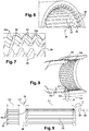
figures 6 et 7 sont des vues schématiques en perspective des cannelures et des dents internes d'un arbre femelle selon l'invention ; - la
figure 8 est une vue schématique en perspective et en coupe axiale d'un ensemble d'arbres selon l'invention ; - la
figure 9 est une vue schématique partielle en perspective de l'arbre mâle desfigures 4 et 5 ; - la
figure 10 est une vue similaire à lafigure 7 et illustrant une variante de réalisation de l'invention ; et - les
figures 11 et 12 sont des vues très schématiques des arbres et de leurs dents de guidage selon la variante de réalisation de lafigure 10 , et représentent deux positions angulaires différentes de l'arbre mâle vis-à-vis de l'arbre femelle. - En se référant à la
figure 1 , on voit une turbomachine 1 à réducteur, qui comporte, de manière classique, une soufflante S, un compresseur basse pression 1a, un compresseur haute pression 1b, une chambre de combustion 1c, une turbine haute pression 1d et une turbine basse pression 1e. Les rotors du compresseur haute pression 1b et de la turbine haute pression 1d sont reliés par un arbre haute pression 5 et forment avec lui un corps haute pression (HP). Les rotors du compresseur basse pression 1a et de la turbine basse pression 1e sont reliés par un arbre basse pression 4 et forment avec lui un corps basse pression (BP). La soufflante est, quant à elle, portée par un arbre de soufflante 3 qui est relié par un réducteur 7 à l'arbre BP 4. - Les arbres HP et BP s'étendent suivant un axe qui est l'axe de rotation de la turbomachine 1. Dans la suite de la description, les notions de longitudinal ou radial, et d'intérieur ou extérieur, sont relatives à cet axe.
- La turbomachine 1 comprend des carters structuraux. Le corps HP est tenu par deux carters structuraux : le carter inter-compresseurs et le carter inter-turbines, et le corps BP est tenu par au moins deux carters structuraux : le carter intermédiaire 2 et le carter inter-turbine et/ou le carter d'échappement 6.
- Le carter intermédiaire 2 soutient des paliers de l'arbre de turbine BP 4 qui sont logés dans une enceinte avant ou amont notée E1. Le carter d'échappement 6 soutient des paliers de l'arbre de turbine BP 4 qui sont logés dans une enceinte arrière ou aval notée E2.
- Les enceintes sont en général délimitées par des supports de paliers.
- Le réducteur 7 est ici de type épicycloïdal. La
figure 2 montre de manière très schématique l'encombrement du réducteur. Le réducteur 7 comprend un solaire qui est engrené avec les satellites et est accouplé par l'intermédiaire de cannelures C1, C2 avec un arbre 8 qui peut être considéré comme l'arbre d'entrée du réducteur. L'arbre 8 est entraîné par l'arbre BP 4 par l'intermédiaire d'un arbre 9 du compresseur BP qui est guidé par un palier 10 aval. En variante, les arbres 8 et 9 pourraient former un unique arbre monobloc. - Les arbres 8, 9 et 4 forment une ligne d'arbres BP. Le couple en sortie du réducteur 7 est transmis à l'arbre de soufflante 3, par une liaison classique, connue de l'homme du métier, comme par exemple une fixation de cet arbre de soufflante sur le porte-satellites formant un arbre de sortie 7a du réducteur, dans le cas d'un réducteur épicycloïdal. Dans le cas d'un réducteur planétaire, l'arbre de soufflante serait entrainé par la couronne. Le réducteur est placé à l'intérieur de l'enceinte avant E1 de lubrification.
- L'enceinte E1 comprend des parois fixes et des parois mobiles. Les parois fixes de l'enceinte E1 comprennent une paroi interne de la veine du flux primaire, d'un support amont de palier 11 et d'un support aval de palier 12. Les supports 11 et 12 s'étendent vers l'intérieur de la turbomachine et portent respectivement les paliers 13, et le palier 10. Ils assurent la structure entre les carters et les bagues externes fixes des paliers. Les parois mobiles de l'enceinte E1 comprennent les arbres d'entrée 8 et de sortie 7a. Les paliers 10, 13, 14 sont logés dans l'enceinte E1. Des étanchéités, non visibles sur les schémas sont prévues entre les parois fixes et mobiles et sont par exemple des joints labyrinthe, joints à brosse, joint radiaux segmenté, etc.
- Les paliers 10, 13 et 14 ainsi que le réducteur 7 sont lubrifiés pour leur bon fonctionnement. L'huile est amenée par des moyens appropriés tels que des gicleurs, des conduits d'amenée d'huile, etc. Les paliers 10, 14 sont situés aux extrémités axiales de l'enceinte E1. Le support de palier 11 comprend des trous de ventilation qui laissent passer de l'air de ventilation de l'enceinte. L'enceinte E1 est configurée pour que le mélange air-huile, qui forme un brouillard d'huile à l'intérieur de l'enceinte, soit contenu dans cette dernière. Entre les parois rotor et stator de l'enceinte, par exemple ici aux extrémités amont et aval de l'enceinte, des étanchéités (telles que des labyrinthes) sont placées pour contenir l'huile, et un circuit d'air vient pressuriser ces étanchéités pour éviter les fuites d'huile. L'enceinte E1 se trouve alors pressurisée (de l'air y entre en continu, repoussant l'huile qui aurait pu sortir des étanchéités par capillarité) et les paliers fonctionnent dans un milieu d'huile et d'air mélangés. L'alimentation des paliers est assurée par un tube d'alimentation et la récupération est assurée par un tube de récupération spécifique. Pour éviter une surpression de l'enceinte, et permettre un flux constant d'air entrant, l'intérieur de l'enceinte est mise à l'air à pression plus faible que la pression de l'air entrant dans les étanchéités. Cet air chargé de particules d'huile, qui est évacué au niveau d'un puits de pression, doit d'abord être traité pour récupérer la quasi-totalité de l'huile qu'il véhicule. Pour cela, l'air huilé sera amené à un déshuileur qui séparera l'air de l'huile qu'il véhicule et rejettera l'air déshuilé à l'extérieur du moteur. C'est le principe de déshuilage d'une enceinte.
- La
figure 3 montre une étape d'assemblage de la turbomachine 1 dans laquelle un module amont 20 comportant l'arbre de soufflante 3, le support 11 des paliers 13, 14, et le réducteur 7, sont déplacés en translation le long de l'axe de la turbomachine jusqu'à l'accouplement de son solaire avec l'arbre 8. - Le solaire du réducteur est un arbre femelle à cannelures internes, et l'arbre 8 est un arbre mâle à cannelures externes. L'inverse est envisageable en variante. Les cannelures des arbres sont rectilignes et longitudinales. Elles sont complémentaires et destinées à coopérer les unes avec les autres pour assurer la transmission d'un couple entre l'arbre BP et le solaire du réducteur. Lorsque les arbres sont engagés l'un sur l'autre, le module amont 20 peut être fixé au reste de la turbomachine, par exemple par l'intermédiaire de brides annulaires de fixation 22 et de vis de serrage de ces brides. Le montage est préférentiellement réalisé avec l'axe de la turbomachine s'étendant à la verticale de façon à ce que le poids du réducteur ne fasse pas fléchir l'arbre de soufflante et de façon à mieux gérer les jeux internes du réducteur.
- L'invention concerne plus particulièrement l'assemblage d'arbres par emmanchement mâle-femelle, les
figures 1 à 3 et suivantes constituant un exemple d'application de cette invention. - Les
figures 4, 5 et9 représentent un arbre mâle 22, qui est l'arbre 8 dans l'exemple précité. - Cet arbre comprend des cannelures externes 24 rectilignes qui s'étendent sur une longueur notée L1. L'arbre 22 comprend en outre une rangée annulaire de dents externes 26 de guidage. Les dents externes 26 sont alignées axialement avec les cannelures externes 24 et ont en section transversale une forme et des dimensions similaires à celles des cannelures externes. Dans l'exemple représenté, les cannelures 34 ont en section une forme générale trapézoïdale (
figure 5 ). Elles comportent chacune un sommet longitudinal plat s'étendant entre deux flancs latéraux préférentiellement plan, inclinés l'un par rapport à l'autre d'un angle compris entre 30 et 80°. Leurs extrémités longitudinales, respectivement amont et aval, sont en outre biseautées de façon à présenter des faces frontales et d'extrémité inclinées par rapport à des plans perpendiculaires à l'axe d'engagement des cannelures et passant par ces extrémités (figure 9 ). - Les dents 26 ont ici une longueur notée L2 et sont séparées axialement des cannelures 24 d'une distance notée L3. En pratique, les dents pourraient être obtenues en réalisant dans un premier temps des cannelures de longueur L1+L2+L3 puis en usinant une gorge annulaire 28 de longueur L2 pour séparer les cannelures définitives des dents de guidage.
- Afin de limiter la masse des arbres, les sections inutiles de matière peuvent être limitées. Par exemple, la section en fond de gorge 28 peut être limitée au minimum suffisant pour tenir les dents 26. La section S1 en fond de gorge est par exemple au moins deux fois inférieure à la section S2 en fond de rainure inter-cannelures qui elle doit absorber le couple à transmettre (
figure 8 ). - Comme cela est visible à la
figure 5 , les dents internes 26 comportent des bords périphériques chanfreinés 30 du côté opposé aux cannelures internes 24, qui facilitent en outre le positionnement respectif des arbres. Les bords chanfreinés 30 sont avantageusement reliés aux surfaces adjacentes, et en particulier aux faces frontales 26a des dents, par des congés de raccordement 26b afin de supprimer les arêtes vives et limiter les risques d'endommagement par contact. Les congés 26b se présentent sous la forme d'arrondis convexes (figure 5 ). - Comme c'est le cas des cannelures, les dents ont leurs extrémités amont biseautées de sorte que leurs faces frontales 26a sont inclinées par rapport à un plan perpendiculaire à l'axe d'engagement des cannelures (
figure 9 ). Les extrémités aval sont ici non biseautées et comprennent des faces d'extrémités perpendiculaires à l'axe d'engagement. - Les angles des chanfreins sont déterminés pour favoriser le positionnement des pièces lors de la manœuvre d'emmanchement. La longueur et la forme des chanfreins, ainsi que la forme de la face frontale 26a des dents 26 (en triangle par opposition à la forme en trapèze des cannelures) permet de maximiser la probabilité d'engagement des dents de positionnement les unes par rapport aux autres sans choc frontal.
- Les
figures 6 et 7 représentent un arbre femelle 32, qui est le solaire du réducteur ou un arbre solidaire du solaire, dans l'exemple précité. - Cet arbre comprend des cannelures internes 34 rectilignes qui s'étendent sur une longueur notée L4. L'arbre comprend en outre une rangée annulaire de dents internes 36 de guidage. Les dents internes 36 sont alignées axialement avec les cannelures internes 34 et ont en section transversale une forme et des dimensions similaires à celles des cannelures externes. Dans l'exemple représenté, les cannelures 34 ont en section une forme générale trapézoïdale (
figure 7 ). Elles comportent chacune un sommet longitudinal plat s'étendant entre deux flancs latéraux préférentiellement plan, inclinés l'un par rapport à l'autre d'un angle compris entre 30 et 80°. Leurs extrémités longitudinales, respectivement amont et aval, sont en outre biseautées de façon à présenter des faces frontales et d'extrémité inclinées par rapport à des plans perpendiculaires à l'axe d'engagement des cannelures et passant par ces extrémités (figures 8 et 9 ). - Les dents 36 ont ici une longueur notée L5 et sont séparées axialement des cannelures d'une distance notée L6. En pratique, les dents 36 pourraient être obtenues en réalisant dans un premier temps des cannelures 34 de longueur L4+L5+L6 puis en usinant une gorge annulaire 38 de longueur L5 pour séparer les cannelures définitives des dents de guidage.
- La section S3 en fond de gorge 38 est par exemple au moins deux fois inférieure à la section S4 en fond de rainure entre deux cannelures internes 34 qui elle doit absorber le couple à transmettre (
figure 8 ). De même, la section S1 en fond de gorge 28 est par exemple au moins deux fois inférieure à la section S3 en fond de rainure entre deux cannelures externes 24 qui elle doit absorber le couple à transmettre. - Comme cela est visible à la
figure 7 , les dents internes 36 comportent des bords périphériques 40 chanfreinés du côté opposé aux cannelures internes 34, qui facilitent en outre le positionnement respectif des arbres. - Les bords chanfreinés 40 sont avantageusement reliés aux surfaces adjacentes, et en particulier aux faces frontales 36a des dents, par des congés de raccordement 36b afin de supprimer les arêtes vives et limiter les risques d'endommagement par contact. Les congés 36b se présentent sous la forme d'arrondis convexes (
figure 7 ). Comme c'est le cas des cannelures, les dents ont leurs extrémités amont biseautées de sorte que leurs faces frontales 36a sont inclinées par rapport à un plan perpendiculaire à l'axe d'engagement des cannelures (figure 8 ). Les extrémités aval sont ici non biseautées et comprennent des faces d'extrémités perpendiculaires à l'axe d'engagement. - Les angles des chanfreins sont déterminés pour favoriser le positionnement des pièces lors de la manœuvre d'emmanchement. La longueur et la forme des chanfreins, ainsi que la forme de la face amont ou d'attaque des dents 36 (en triangle par opposition à a forme en trapèze des cannelures) permet de maximiser la probabilité d'engagement des dents de positionnement les unes par rapport aux autres sans choc frontal.
- Avantageusement, la distance ou longueur L2 est inférieure à la longueur L4, et la distance ou longueur L5 est inférieure à la longueur L1. Cela permet d'éviter aux dents d'un arbre de se retrouver libre de tourner dans la gorge de l'autre arbre, située entre les dents et les cannelures de cet autre arbre. Toutefois, L2 n'est pas nécessairement inférieure à L4 et L5 n'est pas nécessairement inférieure à L1.
- Dans l'exemple représenté, ce qui permet d'éviter aux dents d'un arbre de se retrouver libre de tourner dans la gorge de l'autre arbre est:
- les dents internes 36 sont séparées axialement des cannelures internes 34 du premier arbre 32 d'une distance L6 qui est inférieure à la dimension axiale L2 des dents externes 26, et
- les dents externes 26 sont séparées axialement des cannelures externes 24 du second arbre 22 d'une distance L3 qui est inférieure à la dimension axiale L5 des dents internes 36.
- La
figure 8 montre une étape d'assemblage par insertion des arbres 22, 32. Les arbres sont alignés puis sont engagés l'un dans l'autre. Lors de la phase d'approche, les dents 26, 36 des arbres peuvent coopérer par appui et glissement de leurs bords chanfreinés 30, 40 jusqu'à ce qu'elles soient positionnées pour permettre leur engagement les unes entre les autres. Les cannelures 24, 34 des arbres sont alors alignées axialement de façon à pouvoir être emmanchées les unes dans les autres sans risque de contact, et les arbres peuvent être déplacés l'un dans l'autre jusqu'à leur position d'accouplement. Dans cette position, les cannelures coopèrent entre elles dans une zone axiale d'accouplement notée Z, qui a globalement une longueur de l'ordre de L1 ou L4 (figure 9 ). Les dents 24, 34 sont situées en dehors de cette zone et ne participent pas à la transmission de couple. Même si elles se sont abîmées lors du montage, elles ne risquent donc pas de générer de criques ou de fissures du fait qu'elles sont éloignées axialement de la zone Z. - Dans l'exemple représenté aux
figures 4 à 9 , le nombre de dents 24, 34 de l'arbre 22, 32 est identique au nombre de dents de l'autre arbre. - Dans la variante de réalisation des
figures 10 à 12 , les arbres 22', 32' ont un nombre de dents 26', 36' inférieur au nombre de leurs cannelures. L'arbre interne 22' a un nombre de dents 26' inférieur au nombre de ses cannelures et au nombre de dents 36' de l'arbre externe 32'. L'arbre 22' comprend une rangée annulaire de dents 26' régulièrement espacées les unes des autres d'un pas égal au double du pas entre ses cannelures. - L'arbre externe 32' a un nombre de dents 36' inférieur au nombre de ses cannelures 34'. L'arbre 32' comprend ici une rangée annulaire de paires de dents 36' consécutives, les dents de chaque paire délimitant entre elles un espace de passage d'une dent 26' de l'autre arbre. Le pas entre les dents 36' de chaque paire est égal au pas entre les cannelures 34' du même arbre.
- Les cannelures 24, 34 sont configurées pour transmettre un couple important entre les arbres.
- La limitation du nombre de dents 26', 36' permet de réduire l'impact de la présence des dents sur la masse des arbres 22', 32'. Les dents en trop peuvent être supprimées d'un arbre par usinage par exemple. Par ailleurs, dans le cas de l'arbre externe, comme une partie seulement des dents de chaque paire est destinée à coopérer avec une dent de l'autre arbre, qui est destinée à passer entre les dents de la paire, ces dents 36' peuvent être en partie supprimées pour alléger encore l'arbre 32'. Dans l'exemple représenté, seulement une moitié des dents 36' de chaque paire est conservée.
- Les
figures 11 et 12 montrent que, quelle que soit la position angulaire des arbres l'un par rapport à l'autre, il y aura toujours une série de dents de l'arbre interne qui passera entre des dents d'une paire de dents de l'arbre externe. Dans ces figures, les arbres ont été représentés très schématiquement en les espaçant radialement l'un de l'autre de manière exagérée, pour plus de clarté. Ces figures sont essentiellement utiles pour apprécier le nombre et la répartition des dents ainsi que leurs distributions autour de l'axe de la turbomachine. - Dans les exemples précités, chaque arbre comprend 24 cannelures. Ce nombre n'est bien entendu pas limitatif. Dans les
figures 11 et 12 , l'arbre 22' comprend 12 dents 26' et l'arbre 32' en comprend 18 moitiés de dents 36'. - Le nombre de dents 26', 36' n'est pas limitatif non plus. Le pas entre les dents dépend fortement du nombre de dents des cannelures. Le nombre de dents 26', 36' peut être aménagé avantageusement de sorte à avoir toujours au moins trois contacts distincts entre ces rangées de dents lors du montage, quelle que soit la position angulaire relative des arbres au début du montage. Par exemple, si on a une cannelure de plus de 150 ou 200 dents, on pourrait imaginer avoir des pas représentant l'encombrement de 5, 6 dents ou plus.
- Dans le cadre de la présente invention, l'assemblage de la turbomachine comprend les étapes suivantes, préférentiellement de manière successive, les quatre premières étapes n'ayant qu'un caractère facultatif :
- assembler un module de compresseur basse pression incluant le compresseur basse pression 1a et le carter intermédiaire 2, l'arbre d'entrée 8, aux deux modules précédents.
- positionner le module de compresseur basse pression pour que l'arbre d'entrée 8 soit orienté verticalement.
- assembler un module de réducteur incluant le réducteur 7 au support palier 11, aux paliers de soufflante 13 et 14 et à l'arbre de sortie 7a.
- positionner le module de réducteur au-dessus du module de compresseur basse pression sans contact entre les modules.
- aligner les arbres 22, 32 l'un avec l'autre, qui sont ici l'arbre d'entrée 8 et l'arbre de sortie 7a.
- rapprocher les arbres l'un de l'autre de façon à ce que les dents 26, 36 des arbres coopèrent par appui et glissement jusqu'à ce qu'elles soient positionnées pour permettre leur engagement les unes entre les autres, et que les cannelures 24, 34 des arbres soient alignées axialement de façon à pouvoir être emmanchées les unes dans les autres sans risque de contact, et
- déplacer les arbres l'un dans l'autre jusqu'à leur position d'accouplement, dans laquelle les cannelures coopèrent entre elles dans une zone axiale d'accouplement Z, les dents 24, 34 étant situées en dehors de cette zone et n'étant donc pas destinées à participer à la transmission d'un couple entre les arbres. Cette position d'accouplement est représentée à la
figure 9 où on constate que les dents 26, 36 sont situées de part et d'autre de la zone d'accouplement. - Dans le cas représenté à la
figure 3 où les cannelures 34, 24 des arbres 22, 32 forment respectivement les cannelures C1 et C2 du solaire et de l'arbre 8, les étapes précitées permettent d'assembler le module de soufflante de la turbomachine, qui inclut le module compresseur basse pression et le module réducteur. Ce module est ensuite fixé à un module incluant le corps haute pression puis à un autre module incluant la turbine basse pression et l'arbre basse pression. - Le système d'accouplement décrit dans ce qui précède peut être utilisé pour l'accouplement de plusieurs paires d'arbres d'une turbomachine.
Claims (12)
- Ensemble d'arbres (22, 32) pour une turbomachine (1) d'aéronef, comportant un premier arbre externe (32) et un second arbre interne (22), le premier arbre externe étant destiné à être engagé axialement sur le second arbre et comportant des cannelures longitudinales internes (34) d'accouplement avec des cannelures longitudinales externes (24) du second arbre, caractérisé en ce que :- le premier arbre comprend, en amont des cannelures internes par rapport à la direction d'engagement, une rangée annulaire de dents internes (36) de guidage, les dents internes étant alignées axialement avec des cannelures internes et ayant en section transversale une forme et des dimensions similaires à celles des cannelures internes, et- le second arbre comprend, en amont des cannelures externes par rapport à la direction d'engagement, une rangée annulaire de dents externes (26) de guidage, les dents externes étant alignées axialement avec des cannelures externes et ayant en section transversale une forme et des dimensions similaires à celles des cannelures externes,et en ce que lorsque les premier et second arbres sont en position d'accouplement, les cannelures internes et externes sont engagées l'une dans l'autre et coopèrent entre elles dans une zone axiale (Z) d'accouplement, les dents internes et externes étant situées en dehors de cette zone d'accouplement.
- Ensemble selon la revendication 1, dans lequel, lorsque les premier et second arbres sont en cours de montage l'un dans l'autre, leurs dents sont configurées pour coopérer par appui et glissement les unes avec les autres au début du montage pour assurer l'alignement axial des arbres et de leurs cannelures et éviter que des extrémités axiales en regard des cannelures viennent buter les unes contre les autres.
- Ensemble selon la revendication 1 ou 2, dans lequel les dents internes (36) sont séparées axialement des cannelures internes (34) du premier arbre (32) d'une distance (L6) qui est inférieure à la dimension axiale (L2) des dents externes (26), et/ou les dents externes (26) sont séparées axialement des cannelures externes (24) du second arbre (22) d'une distance (L3) qui est inférieure à la dimension axiale (L5) des dents internes (36).
- Ensemble selon l'une des revendications 1 à 3, dans lequel les dents internes (36) comportent des bords périphériques chanfreinés (40) du côté opposé aux cannelures internes (34), et/ou les dents externes (26) comportent des bords périphériques chanfreinés (30) du côté opposé aux cannelures externes (24).
- Ensemble selon l'une des revendications 1 à 4, dans lequel au moins un des arbres (22, 32) comprend un nombre de dents (26, 36) identique au nombre de ses cannelures (24, 34).
- Ensemble selon l'une des revendications 1 à 4, dans lequel au moins un des arbres (22', 32') comprend un nombre de dents (26', 36') inférieur au nombre de ses cannelures (34').
- Ensemble selon la revendication 6, dans lequel l'un des arbres (22') comprend un nombre de dents (26') inférieur au nombre de dents (36') de l'autre des arbres (32').
- Ensemble selon la revendication 6 ou 7, dans lequel l'un des arbres (22') comprend une rangée annulaire de dents (26') régulièrement espacées les unes des autres d'un pas égal au double du pas entre ses cannelures.
- Ensemble selon la revendication 8, dans lequel l'autre des arbres (32') comprend une rangée annulaire de paires de dents (36'), les dents de chaque paire délimitant entre elles un espace de passage d'une dent (26') de l'autre arbre (22').
- Turbomachine (10) d'aéronef, comportant au moins un ensemble selon l'une des revendications précédentes.
- Turbomachine selon la revendication 10, dans laquelle les premier et second arbres sont un solaire de réducteur et un arbre basse pression, ou deux arbres basse pression.
- Procédé d'assemblage d'une turbomachine selon la revendication 11, comprenant les étapes consistant à :- aligner les arbres (22, 32) l'un avec l'autre,- rapprocher les arbres l'un de l'autre de façon à ce que les dents (26, 36) des arbres coopèrent par appui et glissement jusqu'à ce qu'elles soient positionnées pour permettre leur engagement les unes entre les autres, et que les cannelures (24, 34) des arbres soient alignées axialement de façon à pouvoir être emmanchées les unes dans les autres sans risque de contact, et- déplacer les arbres l'un dans l'autre jusqu'à leur position d'accouplement, dans laquelle les cannelures coopèrent entre elles dans une zone axiale d'accouplement (Z), les dents (24, 34) étant situées en dehors de cette zone et n'étant donc pas destinées à participer pas à la transmission d'un couple entre les arbres.
Applications Claiming Priority (2)
| Application Number | Priority Date | Filing Date | Title |
|---|---|---|---|
| FR1763051A FR3075879B1 (fr) | 2017-12-22 | 2017-12-22 | Ensemble d'arbres pour une turbomachine d'aeronef |
| PCT/FR2018/053444 WO2019122741A1 (fr) | 2017-12-22 | 2018-12-20 | Ensemble d'arbres pour une turbomachine d'aéronef |
Publications (2)
| Publication Number | Publication Date |
|---|---|
| EP3728792A1 EP3728792A1 (fr) | 2020-10-28 |
| EP3728792B1 true EP3728792B1 (fr) | 2021-10-13 |
Family
ID=61521698
Family Applications (1)
| Application Number | Title | Priority Date | Filing Date |
|---|---|---|---|
| EP18842432.9A Active EP3728792B1 (fr) | 2017-12-22 | 2018-12-20 | Ensemble d'arbres pour une turbomachine d'aéronef |
Country Status (5)
| Country | Link |
|---|---|
| US (1) | US11661970B2 (fr) |
| EP (1) | EP3728792B1 (fr) |
| CN (1) | CN111542681B (fr) |
| FR (1) | FR3075879B1 (fr) |
| WO (1) | WO2019122741A1 (fr) |
Families Citing this family (7)
| Publication number | Priority date | Publication date | Assignee | Title |
|---|---|---|---|---|
| FR3098240B1 (fr) * | 2019-07-03 | 2021-07-16 | Safran Aircraft Engines | Agencement de turbomachines d’aeronautique comprenant une pompe de lubrification entrainee par deux engrenages d’angle droit |
| FR3098547B1 (fr) * | 2019-07-08 | 2022-04-29 | Safran Aircraft Engines | Assemblage de maintien d’un train d’engrenages dans une turbomachine |
| US12097897B2 (en) | 2020-09-11 | 2024-09-24 | Steering Solutions Ip Holding Corporation | Intermediate shaft axial retention device |
| FR3115558B1 (fr) * | 2020-10-27 | 2023-12-15 | Safran Aircraft Engines | Dispositif de pressurisation d’une enceinte aval de turbomachine et turbomachine correspondante. |
| FR3148270B1 (fr) * | 2023-04-26 | 2026-04-24 | Renault | Dispositif de transmission de couple entre un générateur de couple et un adaptateur de couple, notamment pour véhicule automobile |
| CN116906458A (zh) * | 2023-07-17 | 2023-10-20 | 江苏新日电动车股份有限公司 | 两端配合式飞轮花键联接结构及电动自行车 |
| FR3162797A1 (fr) * | 2024-06-03 | 2025-12-05 | Safran Aircraft Engines | Turbomachine comprenant plusieurs modules et un dispositif de blocage de ces modules, et procede de montage correspondant |
Family Cites Families (22)
| Publication number | Priority date | Publication date | Assignee | Title |
|---|---|---|---|---|
| DE1026134B (de) * | 1953-01-12 | 1958-03-13 | Fritz Ungerer Dipl Ing | Vorrichtung zur loesbaren Sicherung von Raedern gegen Axialverschiebung |
| US4348956A (en) * | 1980-08-29 | 1982-09-14 | The United States Of America As Represented By The Secretary Of The Army | Artillery shell comprising two sections having complementary coupling members for connecting the sections together |
| DE4332485C1 (de) * | 1993-09-24 | 1995-04-06 | Supervis Ets | Vorrichtung zum Verbinden eines kerbverzahnten, der Übertragung von Drehmomenten dienenden Wellenzapfens |
| US5533825A (en) * | 1994-11-14 | 1996-07-09 | General Electric Company | Parabolically helical spline shaft coupling |
| DE19517258A1 (de) * | 1995-05-11 | 1996-11-14 | Alpha Getriebebau Gmbh | Wellen-Befestigung |
| US6482094B2 (en) * | 2001-03-16 | 2002-11-19 | Schenck Rotec Gmbh | Self-aligning splined male shaft head and engagement method |
| DE10316155B4 (de) * | 2002-05-24 | 2006-04-20 | Sew-Eurodrive Gmbh & Co. Kg | Welle, Baureihe von Wellen und Verfahren zur Fertigung |
| DE10239393A1 (de) * | 2002-08-28 | 2004-03-11 | Zf Friedrichshafen Ag | Welle-Nabe-Verbindung |
| RU2273749C1 (ru) | 2004-08-26 | 2006-04-10 | Открытое акционерное общество "Научно-производственное объединение "Сатурн" (ОАО "НПО "Сатурн") | Узел соединения роторов компрессора и турбины газотурбинного двигателя |
| BRPI0517289B1 (pt) * | 2005-01-03 | 2018-02-27 | Gkn Driveline International Gmbh | Conexão de eixo e cubo, com sistema de segurança |
| JP2006258254A (ja) * | 2005-03-18 | 2006-09-28 | Ntn Corp | 等速ジョイントのシャフト抜け防止構造 |
| FR2909146B1 (fr) | 2006-11-28 | 2009-06-05 | Snecma Sa | Dispositif de liaison de deux arbres rotatifs, en particulier dans une turbomachine. |
| FR2918726A1 (fr) * | 2007-07-11 | 2009-01-16 | Snecma Sa | Accouplement d'arbres par engrenage a denture droite. |
| GB0818249D0 (en) * | 2008-10-07 | 2008-11-12 | Rolls Royce Plc | Splined couplings |
| US20140116184A1 (en) * | 2012-10-31 | 2014-05-01 | Michael W. Clark | Steering wheel retention assembly |
| US20140119810A1 (en) * | 2012-10-31 | 2014-05-01 | Melvin Lee Tinnin | Steering wheel shaft retention mechanism assembly and service tool |
| US9476459B2 (en) * | 2014-01-07 | 2016-10-25 | Hamilton Sundstrand Corporation | Spline lock shaft locking system |
| US9649933B2 (en) * | 2014-05-08 | 2017-05-16 | Gkn Driveline North America, Inc. | Vehicle power transfer unit (PTU) disconnect assembly |
| US20150323014A1 (en) * | 2014-05-08 | 2015-11-12 | Steering Solutions Ip Holding Corporation | Spline press fit orientation lead in |
| JP6622620B2 (ja) * | 2016-02-24 | 2019-12-18 | 日立オートモティブシステムズ株式会社 | プロペラシャフト及びプロペラシャフトの製造方法 |
| DE102016203188A1 (de) * | 2016-02-29 | 2017-08-31 | Bayerische Motoren Werke Aktiengesellschaft | Welle-Nabe-Verbindung |
| KR20180137766A (ko) * | 2017-06-19 | 2018-12-28 | 현대위아 주식회사 | 차량용 휠 구동 유닛 |
-
2017
- 2017-12-22 FR FR1763051A patent/FR3075879B1/fr not_active Expired - Fee Related
-
2018
- 2018-12-20 CN CN201880084963.0A patent/CN111542681B/zh active Active
- 2018-12-20 WO PCT/FR2018/053444 patent/WO2019122741A1/fr not_active Ceased
- 2018-12-20 EP EP18842432.9A patent/EP3728792B1/fr active Active
- 2018-12-20 US US16/954,143 patent/US11661970B2/en active Active
Also Published As
| Publication number | Publication date |
|---|---|
| WO2019122741A1 (fr) | 2019-06-27 |
| US20210164350A1 (en) | 2021-06-03 |
| RU2020121632A (ru) | 2022-01-25 |
| CN111542681B (zh) | 2022-09-20 |
| FR3075879A1 (fr) | 2019-06-28 |
| CN111542681A (zh) | 2020-08-14 |
| FR3075879B1 (fr) | 2019-11-15 |
| RU2020121632A3 (fr) | 2022-03-24 |
| CA3085822A1 (fr) | 2019-06-27 |
| EP3728792A1 (fr) | 2020-10-28 |
| US11661970B2 (en) | 2023-05-30 |
Similar Documents
| Publication | Publication Date | Title |
|---|---|---|
| EP3728792B1 (fr) | Ensemble d'arbres pour une turbomachine d'aéronef | |
| EP3728817B1 (fr) | Turbomachine a reducteur pour un aeronef | |
| EP3892895B1 (fr) | Reducteur mecanique de turbomachine d'aeronef | |
| EP4034797B1 (fr) | Restricteur d'huile pour la lubrification de secours d'un élément de turbomachine d'aéronef | |
| EP4240951B1 (fr) | Modularite d'une turbomachine d'aeronef | |
| FR3084427A1 (fr) | Dispositif de type reducteur mecanique pour une turbomachine | |
| EP3705705A1 (fr) | Réducteur mécanique de turbomachine d'aéronef | |
| FR3075878B1 (fr) | Dispositif d'accouplement de deux arbres de turbomachine d'aeronef | |
| EP4265940B1 (fr) | Reducteur mecanique pour une turbomachine d'aeronef | |
| FR3108947A1 (fr) | Module a reducteur pour une turbomachine d’aeronef | |
| EP3736428B1 (fr) | Gorge de joint rapportée pour accouplement par cannelures | |
| EP4336068B1 (fr) | Porte-satellites pour un réducteur de vitesse d'une turbomachine d'aéronef | |
| EP4411178B1 (fr) | Turbomachine comprenant un reducteur de vitesse ayant des brides de fixation accouplees par un accouplement a dentures | |
| CA3085822C (fr) | Ensemble d'arbres pour une turbomachine d'aeronef | |
| FR3156497A1 (fr) | Gicleur d’huile pour un reducteur de turbomachine d’aeronef | |
| FR3163978A1 (fr) | Reducteur mecanique pour une turbomachine d’aeronef | |
| WO2026003459A1 (fr) | Reducteur mecanique pour une turbomachine d'aeronef | |
| WO2024256774A1 (fr) | Arbre d'accouplement pour une turbomachine d'aeronef | |
| FR3163981A1 (fr) | Reducteur mecanique pour une turbomachine d’aeronef | |
| FR3151640A1 (fr) | Reducteur mecanique pour une turbomachine |
Legal Events
| Date | Code | Title | Description |
|---|---|---|---|
| STAA | Information on the status of an ep patent application or granted ep patent |
Free format text: STATUS: UNKNOWN |
|
| STAA | Information on the status of an ep patent application or granted ep patent |
Free format text: STATUS: THE INTERNATIONAL PUBLICATION HAS BEEN MADE |
|
| PUAI | Public reference made under article 153(3) epc to a published international application that has entered the european phase |
Free format text: ORIGINAL CODE: 0009012 |
|
| STAA | Information on the status of an ep patent application or granted ep patent |
Free format text: STATUS: REQUEST FOR EXAMINATION WAS MADE |
|
| 17P | Request for examination filed |
Effective date: 20200617 |
|
| AK | Designated contracting states |
Kind code of ref document: A1 Designated state(s): AL AT BE BG CH CY CZ DE DK EE ES FI FR GB GR HR HU IE IS IT LI LT LU LV MC MK MT NL NO PL PT RO RS SE SI SK SM TR |
|
| AX | Request for extension of the european patent |
Extension state: BA ME |
|
| DAV | Request for validation of the european patent (deleted) | ||
| DAX | Request for extension of the european patent (deleted) | ||
| GRAP | Despatch of communication of intention to grant a patent |
Free format text: ORIGINAL CODE: EPIDOSNIGR1 |
|
| STAA | Information on the status of an ep patent application or granted ep patent |
Free format text: STATUS: GRANT OF PATENT IS INTENDED |
|
| INTG | Intention to grant announced |
Effective date: 20210525 |
|
| GRAS | Grant fee paid |
Free format text: ORIGINAL CODE: EPIDOSNIGR3 |
|
| GRAA | (expected) grant |
Free format text: ORIGINAL CODE: 0009210 |
|
| STAA | Information on the status of an ep patent application or granted ep patent |
Free format text: STATUS: THE PATENT HAS BEEN GRANTED |
|
| AK | Designated contracting states |
Kind code of ref document: B1 Designated state(s): AL AT BE BG CH CY CZ DE DK EE ES FI FR GB GR HR HU IE IS IT LI LT LU LV MC MK MT NL NO PL PT RO RS SE SI SK SM TR |
|
| REG | Reference to a national code |
Ref country code: GB Ref legal event code: FG4D Free format text: NOT ENGLISH |
|
| REG | Reference to a national code |
Ref country code: CH Ref legal event code: EP |
|
| REG | Reference to a national code |
Ref country code: DE Ref legal event code: R096 Ref document number: 602018025148 Country of ref document: DE |
|
| REG | Reference to a national code |
Ref country code: IE Ref legal event code: FG4D Free format text: LANGUAGE OF EP DOCUMENT: FRENCH |
|
| REG | Reference to a national code |
Ref country code: AT Ref legal event code: REF Ref document number: 1438334 Country of ref document: AT Kind code of ref document: T Effective date: 20211115 |
|
| REG | Reference to a national code |
Ref country code: SE Ref legal event code: TRGR |
|
| REG | Reference to a national code |
Ref country code: LT Ref legal event code: MG9D |
|
| REG | Reference to a national code |
Ref country code: NL Ref legal event code: MP Effective date: 20211013 |
|
| REG | Reference to a national code |
Ref country code: AT Ref legal event code: MK05 Ref document number: 1438334 Country of ref document: AT Kind code of ref document: T Effective date: 20211013 |
|
| PG25 | Lapsed in a contracting state [announced via postgrant information from national office to epo] |
Ref country code: RS Free format text: LAPSE BECAUSE OF FAILURE TO SUBMIT A TRANSLATION OF THE DESCRIPTION OR TO PAY THE FEE WITHIN THE PRESCRIBED TIME-LIMIT Effective date: 20211013 Ref country code: LT Free format text: LAPSE BECAUSE OF FAILURE TO SUBMIT A TRANSLATION OF THE DESCRIPTION OR TO PAY THE FEE WITHIN THE PRESCRIBED TIME-LIMIT Effective date: 20211013 Ref country code: FI Free format text: LAPSE BECAUSE OF FAILURE TO SUBMIT A TRANSLATION OF THE DESCRIPTION OR TO PAY THE FEE WITHIN THE PRESCRIBED TIME-LIMIT Effective date: 20211013 Ref country code: BG Free format text: LAPSE BECAUSE OF FAILURE TO SUBMIT A TRANSLATION OF THE DESCRIPTION OR TO PAY THE FEE WITHIN THE PRESCRIBED TIME-LIMIT Effective date: 20220113 Ref country code: AT Free format text: LAPSE BECAUSE OF FAILURE TO SUBMIT A TRANSLATION OF THE DESCRIPTION OR TO PAY THE FEE WITHIN THE PRESCRIBED TIME-LIMIT Effective date: 20211013 |
|
| PG25 | Lapsed in a contracting state [announced via postgrant information from national office to epo] |
Ref country code: IS Free format text: LAPSE BECAUSE OF FAILURE TO SUBMIT A TRANSLATION OF THE DESCRIPTION OR TO PAY THE FEE WITHIN THE PRESCRIBED TIME-LIMIT Effective date: 20220213 Ref country code: PT Free format text: LAPSE BECAUSE OF FAILURE TO SUBMIT A TRANSLATION OF THE DESCRIPTION OR TO PAY THE FEE WITHIN THE PRESCRIBED TIME-LIMIT Effective date: 20220214 Ref country code: PL Free format text: LAPSE BECAUSE OF FAILURE TO SUBMIT A TRANSLATION OF THE DESCRIPTION OR TO PAY THE FEE WITHIN THE PRESCRIBED TIME-LIMIT Effective date: 20211013 Ref country code: NO Free format text: LAPSE BECAUSE OF FAILURE TO SUBMIT A TRANSLATION OF THE DESCRIPTION OR TO PAY THE FEE WITHIN THE PRESCRIBED TIME-LIMIT Effective date: 20220113 Ref country code: NL Free format text: LAPSE BECAUSE OF FAILURE TO SUBMIT A TRANSLATION OF THE DESCRIPTION OR TO PAY THE FEE WITHIN THE PRESCRIBED TIME-LIMIT Effective date: 20211013 Ref country code: LV Free format text: LAPSE BECAUSE OF FAILURE TO SUBMIT A TRANSLATION OF THE DESCRIPTION OR TO PAY THE FEE WITHIN THE PRESCRIBED TIME-LIMIT Effective date: 20211013 Ref country code: HR Free format text: LAPSE BECAUSE OF FAILURE TO SUBMIT A TRANSLATION OF THE DESCRIPTION OR TO PAY THE FEE WITHIN THE PRESCRIBED TIME-LIMIT Effective date: 20211013 Ref country code: GR Free format text: LAPSE BECAUSE OF FAILURE TO SUBMIT A TRANSLATION OF THE DESCRIPTION OR TO PAY THE FEE WITHIN THE PRESCRIBED TIME-LIMIT Effective date: 20220114 Ref country code: ES Free format text: LAPSE BECAUSE OF FAILURE TO SUBMIT A TRANSLATION OF THE DESCRIPTION OR TO PAY THE FEE WITHIN THE PRESCRIBED TIME-LIMIT Effective date: 20211013 |
|
| REG | Reference to a national code |
Ref country code: DE Ref legal event code: R097 Ref document number: 602018025148 Country of ref document: DE |
|
| PG25 | Lapsed in a contracting state [announced via postgrant information from national office to epo] |
Ref country code: SM Free format text: LAPSE BECAUSE OF FAILURE TO SUBMIT A TRANSLATION OF THE DESCRIPTION OR TO PAY THE FEE WITHIN THE PRESCRIBED TIME-LIMIT Effective date: 20211013 Ref country code: SK Free format text: LAPSE BECAUSE OF FAILURE TO SUBMIT A TRANSLATION OF THE DESCRIPTION OR TO PAY THE FEE WITHIN THE PRESCRIBED TIME-LIMIT Effective date: 20211013 Ref country code: RO Free format text: LAPSE BECAUSE OF FAILURE TO SUBMIT A TRANSLATION OF THE DESCRIPTION OR TO PAY THE FEE WITHIN THE PRESCRIBED TIME-LIMIT Effective date: 20211013 Ref country code: MC Free format text: LAPSE BECAUSE OF FAILURE TO SUBMIT A TRANSLATION OF THE DESCRIPTION OR TO PAY THE FEE WITHIN THE PRESCRIBED TIME-LIMIT Effective date: 20211013 Ref country code: EE Free format text: LAPSE BECAUSE OF FAILURE TO SUBMIT A TRANSLATION OF THE DESCRIPTION OR TO PAY THE FEE WITHIN THE PRESCRIBED TIME-LIMIT Effective date: 20211013 Ref country code: DK Free format text: LAPSE BECAUSE OF FAILURE TO SUBMIT A TRANSLATION OF THE DESCRIPTION OR TO PAY THE FEE WITHIN THE PRESCRIBED TIME-LIMIT Effective date: 20211013 Ref country code: CZ Free format text: LAPSE BECAUSE OF FAILURE TO SUBMIT A TRANSLATION OF THE DESCRIPTION OR TO PAY THE FEE WITHIN THE PRESCRIBED TIME-LIMIT Effective date: 20211013 |
|
| REG | Reference to a national code |
Ref country code: CH Ref legal event code: PL |
|
| PLBE | No opposition filed within time limit |
Free format text: ORIGINAL CODE: 0009261 |
|
| STAA | Information on the status of an ep patent application or granted ep patent |
Free format text: STATUS: NO OPPOSITION FILED WITHIN TIME LIMIT |
|
| 26N | No opposition filed |
Effective date: 20220714 |
|
| REG | Reference to a national code |
Ref country code: BE Ref legal event code: MM Effective date: 20211231 |
|
| PG25 | Lapsed in a contracting state [announced via postgrant information from national office to epo] |
Ref country code: IE Free format text: LAPSE BECAUSE OF NON-PAYMENT OF DUE FEES Effective date: 20211220 Ref country code: AL Free format text: LAPSE BECAUSE OF FAILURE TO SUBMIT A TRANSLATION OF THE DESCRIPTION OR TO PAY THE FEE WITHIN THE PRESCRIBED TIME-LIMIT Effective date: 20211013 Ref country code: LU Free format text: LAPSE BECAUSE OF NON-PAYMENT OF DUE FEES Effective date: 20211220 |
|
| PG25 | Lapsed in a contracting state [announced via postgrant information from national office to epo] |
Ref country code: SI Free format text: LAPSE BECAUSE OF FAILURE TO SUBMIT A TRANSLATION OF THE DESCRIPTION OR TO PAY THE FEE WITHIN THE PRESCRIBED TIME-LIMIT Effective date: 20211013 Ref country code: BE Free format text: LAPSE BECAUSE OF NON-PAYMENT OF DUE FEES Effective date: 20211231 |
|
| PG25 | Lapsed in a contracting state [announced via postgrant information from national office to epo] |
Ref country code: LI Free format text: LAPSE BECAUSE OF NON-PAYMENT OF DUE FEES Effective date: 20211231 Ref country code: CH Free format text: LAPSE BECAUSE OF NON-PAYMENT OF DUE FEES Effective date: 20211231 |
|
| PG25 | Lapsed in a contracting state [announced via postgrant information from national office to epo] |
Ref country code: CY Free format text: LAPSE BECAUSE OF FAILURE TO SUBMIT A TRANSLATION OF THE DESCRIPTION OR TO PAY THE FEE WITHIN THE PRESCRIBED TIME-LIMIT Effective date: 20211013 |
|
| PG25 | Lapsed in a contracting state [announced via postgrant information from national office to epo] |
Ref country code: HU Free format text: LAPSE BECAUSE OF FAILURE TO SUBMIT A TRANSLATION OF THE DESCRIPTION OR TO PAY THE FEE WITHIN THE PRESCRIBED TIME-LIMIT; INVALID AB INITIO Effective date: 20181220 |
|
| PG25 | Lapsed in a contracting state [announced via postgrant information from national office to epo] |
Ref country code: MK Free format text: LAPSE BECAUSE OF FAILURE TO SUBMIT A TRANSLATION OF THE DESCRIPTION OR TO PAY THE FEE WITHIN THE PRESCRIBED TIME-LIMIT Effective date: 20211013 |
|
| PG25 | Lapsed in a contracting state [announced via postgrant information from national office to epo] |
Ref country code: TR Free format text: LAPSE BECAUSE OF FAILURE TO SUBMIT A TRANSLATION OF THE DESCRIPTION OR TO PAY THE FEE WITHIN THE PRESCRIBED TIME-LIMIT Effective date: 20211013 |
|
| PG25 | Lapsed in a contracting state [announced via postgrant information from national office to epo] |
Ref country code: MT Free format text: LAPSE BECAUSE OF FAILURE TO SUBMIT A TRANSLATION OF THE DESCRIPTION OR TO PAY THE FEE WITHIN THE PRESCRIBED TIME-LIMIT Effective date: 20211013 |
|
| PGFP | Annual fee paid to national office [announced via postgrant information from national office to epo] |
Ref country code: GB Payment date: 20251229 Year of fee payment: 8 |
|
| PGFP | Annual fee paid to national office [announced via postgrant information from national office to epo] |
Ref country code: FR Payment date: 20251222 Year of fee payment: 8 |
|
| PGFP | Annual fee paid to national office [announced via postgrant information from national office to epo] |
Ref country code: SE Payment date: 20251217 Year of fee payment: 8 |
|
| PGFP | Annual fee paid to national office [announced via postgrant information from national office to epo] |
Ref country code: DE Payment date: 20251222 Year of fee payment: 8 |
|
| PGFP | Annual fee paid to national office [announced via postgrant information from national office to epo] |
Ref country code: IT Payment date: 20251231 Year of fee payment: 8 |