EP3728062B1 - Packaging system for aseptic filling of small volume vials - Google Patents
Packaging system for aseptic filling of small volume vials Download PDFInfo
- Publication number
- EP3728062B1 EP3728062B1 EP18837072.0A EP18837072A EP3728062B1 EP 3728062 B1 EP3728062 B1 EP 3728062B1 EP 18837072 A EP18837072 A EP 18837072A EP 3728062 B1 EP3728062 B1 EP 3728062B1
- Authority
- EP
- European Patent Office
- Prior art keywords
- stopper
- hinged
- arm
- base
- leg
- Prior art date
- Legal status (The legal status is an assumption and is not a legal conclusion. Google has not performed a legal analysis and makes no representation as to the accuracy of the status listed.)
- Active
Links
Images














Classifications
-
- B—PERFORMING OPERATIONS; TRANSPORTING
- B65—CONVEYING; PACKING; STORING; HANDLING THIN OR FILAMENTARY MATERIAL
- B65B—MACHINES, APPARATUS OR DEVICES FOR, OR METHODS OF, PACKAGING ARTICLES OR MATERIALS; UNPACKING
- B65B7/00—Closing containers or receptacles after filling
- B65B7/16—Closing semi-rigid or rigid containers or receptacles not deformed by, or not taking-up shape of, contents, e.g. boxes or cartons
- B65B7/28—Closing semi-rigid or rigid containers or receptacles not deformed by, or not taking-up shape of, contents, e.g. boxes or cartons by applying separate preformed closures, e.g. lids, covers
- B65B7/2821—Closing semi-rigid or rigid containers or receptacles not deformed by, or not taking-up shape of, contents, e.g. boxes or cartons by applying separate preformed closures, e.g. lids, covers applying plugs or threadless stoppers
-
- B—PERFORMING OPERATIONS; TRANSPORTING
- B65—CONVEYING; PACKING; STORING; HANDLING THIN OR FILAMENTARY MATERIAL
- B65B—MACHINES, APPARATUS OR DEVICES FOR, OR METHODS OF, PACKAGING ARTICLES OR MATERIALS; UNPACKING
- B65B43/00—Forming, feeding, opening or setting-up containers or receptacles in association with packaging
- B65B43/42—Feeding or positioning bags, boxes, or cartons in the distended, opened, or set-up state; Feeding preformed rigid containers, e.g. tins, capsules, glass tubes, glasses, to the packaging position; Locating containers or receptacles at the filling position; Supporting containers or receptacles during the filling operation
- B65B43/54—Means for supporting containers or receptacles during the filling operation
-
- B—PERFORMING OPERATIONS; TRANSPORTING
- B65—CONVEYING; PACKING; STORING; HANDLING THIN OR FILAMENTARY MATERIAL
- B65B—MACHINES, APPARATUS OR DEVICES FOR, OR METHODS OF, PACKAGING ARTICLES OR MATERIALS; UNPACKING
- B65B67/00—Apparatus or devices facilitating manual packaging operations; Sack holders
- B65B67/02—Packaging of articles or materials in containers
-
- B—PERFORMING OPERATIONS; TRANSPORTING
- B65—CONVEYING; PACKING; STORING; HANDLING THIN OR FILAMENTARY MATERIAL
- B65B—MACHINES, APPARATUS OR DEVICES FOR, OR METHODS OF, PACKAGING ARTICLES OR MATERIALS; UNPACKING
- B65B7/00—Closing containers or receptacles after filling
- B65B7/16—Closing semi-rigid or rigid containers or receptacles not deformed by, or not taking-up shape of, contents, e.g. boxes or cartons
- B65B7/161—Sealing filled ampoules
-
- B—PERFORMING OPERATIONS; TRANSPORTING
- B65—CONVEYING; PACKING; STORING; HANDLING THIN OR FILAMENTARY MATERIAL
- B65D—CONTAINERS FOR STORAGE OR TRANSPORT OF ARTICLES OR MATERIALS, e.g. BAGS, BARRELS, BOTTLES, BOXES, CANS, CARTONS, CRATES, DRUMS, JARS, TANKS, HOPPERS, FORWARDING CONTAINERS; ACCESSORIES, CLOSURES, OR FITTINGS THEREFOR; PACKAGING ELEMENTS; PACKAGES
- B65D71/00—Bundles of articles held together by packaging elements for convenience of storage or transport, e.g. portable segregating carrier for plural receptacles such as beer cans or pop bottles; Bales of material
- B65D71/50—Bundles of articles held together by packaging elements for convenience of storage or transport, e.g. portable segregating carrier for plural receptacles such as beer cans or pop bottles; Bales of material comprising a plurality of articles held together only partially by packaging elements formed otherwise than by folding a blank
-
- B—PERFORMING OPERATIONS; TRANSPORTING
- B67—OPENING, CLOSING OR CLEANING BOTTLES, JARS OR SIMILAR CONTAINERS; LIQUID HANDLING
- B67B—APPLYING CLOSURE MEMBERS TO BOTTLES JARS, OR SIMILAR CONTAINERS; OPENING CLOSED CONTAINERS
- B67B1/00—Closing bottles, jars or similar containers by applying stoppers
- B67B1/04—Closing bottles, jars or similar containers by applying stoppers by inserting threadless stoppers, e.g. corks
-
- B—PERFORMING OPERATIONS; TRANSPORTING
- B65—CONVEYING; PACKING; STORING; HANDLING THIN OR FILAMENTARY MATERIAL
- B65B—MACHINES, APPARATUS OR DEVICES FOR, OR METHODS OF, PACKAGING ARTICLES OR MATERIALS; UNPACKING
- B65B3/00—Packaging plastic material, semiliquids, liquids or mixed solids and liquids, in individual containers or receptacles, e.g. bags, sacks, boxes, cartons, cans, or jars
- B65B3/003—Filling medical containers such as ampoules, vials, syringes or the like
Definitions
- This application relates to the field of filling of medicine containers, and more particularly to small-volume, aseptic filling of medicine containers.
- Small-volume, aseptic medicine filling containers are increasingly needed due in part to a rise in biologic drugs and personalized medicine which are typically made in small volume batches.
- the drug-filling application commonly requires a system with a high level of component quality, but adapted for use at a relatively small scale, with a relatively small number of medicine containers being filled in a particular batch, while maintaining sterility.
- one option is for the operator to handle, fill, and stopper medicine containers such as medicine vials individually.
- Another option is for the operator to engage in an "assisted hand fill operation" in which medicine containers are filled in small batches with the assistance of fixtures, tools, or other elements that increase the efficiency and ease of the operation as compared to repeating an individual filling operation.
- the devices and systems disclosed herein may be advantageously used in an assisted-hand fill operation.
- US-A-2,998,686 describe a packaging system according to the preamble of claim 1.
- the invention provides a packaging system for filling and sealing with a stopper at least one container according to independent claims 1,6 and 12. Preferred embodiments of the invention are disclosed in the dependent claims.
- a packaging system for filling and sealing with a stopper at least one medicine container having a fill opening.
- the packaging system comprises a container tray having a container cell for receiving and stabilizing the medicine container.
- a stopper holder with a stopper cell forms a closed body with a distal opening, an interior space, a proximal wall opposite the distal opening, and a proximal outer surface.
- the stopper cell is configured for releasably securing the stopper.
- the stopper cell is adapted to release the stopper into the fill opening of the medicine container when a compressive force is exerted on the proximal outer surface of the stopper cell.
- the packaging system comprises a container tray having a container cell for receiving and stabilizing the medicine container.
- the packaging system also comprises a shuttle having an exterior surface and an interior surface. The interior surface is configured for releasably securing the stopper.
- the shuttle is configured to release the stopper into the fill opening upon application of a releasing force to the exterior surface of the shuttle.
- a shuttle tray has a shuttle cell, and the shuttle cell forms a closed body with a proximal opening, an interior space, a bottom inner surface opposite the proximal opening, and a side inner surface. The shuttle cell releasably secures the shuttle.
- the packaging system comprises a container tray having a container cell for receiving and stabilizing the medicine container.
- the packaging system also comprises a stopper clip with a stopper cell.
- the stopper cell comprising a hinged base having first and second hinged-base legs.
- the first hinged-base leg has a first proximal hinged-base-leg end and a first distal hinged-base-leg end.
- the second hinged-base leg has a second proximal hinged-base-leg end and a second distal hinged-base-leg end.
- the first and second proximal hinged-base-leg ends are joined to each other by a hinge.
- the hinge is biased to urge the first and second distal hinged-base-leg ends toward one another to a first position.
- the first hinged-base leg has a first lever extending proximally therefrom, and the second hinged-base leg has a second lever extending proximally therefrom.
- the first lever has a first interior lever surface facing the second lever and a first exterior lever surface facing opposite the first interior lever surface.
- the second lever has a second interior lever surface facing the first lever and a second exterior lever surface facing opposite the second interior lever surface.
- the first lever and the second lever are in spaced relation such that, upon the application of a first compressive force to the first exterior lever surface and the second exterior lever surface, the first base leg and the second base leg are urged to a second position, with the first and second hinged-base legs being spaced apart to allow insertion of the stopper between the first and second hinged-base legs to be releasably secured therebetween. Upon removal of the first compressive force, the first and second hinged-base legs are urged to a third position to releasably secure the stopper therebetween.
- a first embodiment of a packaging system 10 includes a medicine container, which is in the illustrated embodiments is a conventional drug vial 20 (see Fig. 17 ) having a fill opening 22 and a vial flange 23.
- the packaging system also includes a stopper 200 ( Figs. 13-16 ) for sealing the fill opening of the vial 20.
- the example of a stopper 200 shown herein has a major portion 202 with a major diameter 204, and a minor portion 206 with a minor diameter 208.
- the minor portion 206 has a bore 210 and a tapered lower-end portion 212.
- the packaging system 10 preferably comprises a second vial 20 and a second stopper 200 and more preferably a plurality of vials 20 and a plurality of stoppers 200 for sealing the plurality of vials 20.
- a container tray 100 preferably includes a plurality of container cells 120 for receiving and stabilizing a corresponding plurality of the vials 20.
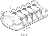
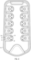
- the container tray 100 is preferably constructed of molded polymeric material with the container cells 120 formed therein by the molding process, as best shown in Figs. 2 and 3 .
- the container tray 100 may aid a user in an assisted-hand-filling operation by stably holding the vials 20 so that the user may conveniently insert a stopper 200 into the opening 22 of each vial 20.
- each container cell 120 includes a snap mechanism formed by two sidewall flexible legs 124 and a flexible latch 122 attached to the container cell 120 for releasably securing the vial 20 in the container cell 120.
- Each container cell 120 is generally in the form of a truncated trough with an open end 120a.
- Each of the two side wall legs 124 includes a chamfered latch 124a at a top end thereof extending radially inwardly with respect to the container cell 120.
- the latch 122 is positioned just inwardly of the open end 120a.
- the side wall legs 124 and latch 122 are positioned triangularly to releasably, slidably, and securely receive the vial 20.
- the chamfered latch 124a extends over a shoulder 21 of the vial 20 in a snap-fit manner when the vial 20 is positioned in the container cell 120.
- the packaging system 10 also preferably includes a stopper holder 300, which in the illustrated embodiment includes a central panel 310 and with two side panels 312 joined thereto by living hinges 314.
- Each living hinge described herein, including without limitation the living hinge 314, is preferably a thinned portion of the same material as the two parts joined by the living hinge, in this case the side panels 312.
- the living hinge 314 is disposed between the two side panels 312 to allow pivoting motion therebetween.
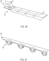
- a stopper holder 300' may have a row of stopper cells 320' arranged linearly in a single, generally planar strip, as shown in Figs. 36 and 37 .
- the stopper cells 320' may be sealed by adhesive panels 330'.
- the stopper cells 320' may have minimal side walls, or the side walls may even be eliminated entirely.
- the stopper holder 300, 300' is preferably constructed of a molded polymeric material.
- each stopper cell 320 may form a generally cylindrically shaped closed body with a distal opening 322, an interior space 324, a proximal inner surface 326 opposite the distal opening 322, a side wall 328, a proximal outer surface 330, and a side outer surface space 332.
- a proximal wall 325 is formed between the proximal inner and outer surfaces 326, 330.
- the side wall 328 may be formed with a minimal height or eliminated entirely, leaving a stopper cell 320' (see Figs. 36 and 37 ) that is essentially dome-shaped (i.e., the proximal outer surface 330 would interface with the side panel 312).
- the stopper cell 320 releasably secures the stopper 200 therein and is adapted to release the stopper 200 into the fill opening 22 of the vial 20 when a compressive force is exerted on the proximal outer surface 330 of the stopper cell 300.
- the securing of the stopper 200 preferably occurs through an interference friction fit, preferably a mild interference fit, between the stopper 200 and the side inner surface 328 of the stopper cell 320.
- the proximal outer surface 330 of the stopper cell 320 is preferably curved outwardly with respect to the interior space 324.
- the stopper cell 320 is preferably constructed by thermoforming of a flexible polymer, such as polyethylene or PETG (polyethylene terephthalate glycol-modified, from which at least a portion of the stopper cell 320 (such as the proximal wall 325 and the side wall 328), and the stopper holder 300, may be formed.
- a flexible polymer such as polyethylene or PETG (polyethylene terephthalate glycol-modified, from which at least a portion of the stopper cell 320 (such as the proximal wall 325 and the side wall 328), and the stopper holder 300, may be formed.
- the stopper cell 320 may be constructed from a rigid material and have a living hinge along the interface between the stopper cell 320 and the side panel 312 or between the proximal wall 330 and the sidewall 328. Referring particularly to Figs.
- the proximal outer surface 330 of the stopper cell 300 flexes inwardly when the compressive force, such as that which may be applied by a finger tip 331, is exerted thereon, and the proximal wall 325 flexes toward the stopper 200 and exerts a compressive force on the stopper 200 to urge the stopper 200 from the stopper cell 320 and into the fill opening 22 of the vial 20.
- the container cells 120 may be configured to releasably secure the vials 20 at an outward angle with respect to the container tray 100. This configuration presents the fill openings 22 at a favorable angle for the user to insert the stoppers 200 into the fill openings 22.
- a second embodiment of a packaging system 410 includes a medicine container in the form of one or more vials 20, the container tray 100, and a corresponding number of stoppers 200 as described above.
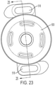
- a shuttle 500 ( Figs. 22-25 ) has an exterior surface 502 and an interior surface 504. The interior surface 504 is configured for releasably gripping the stopper 200.
- the shuttle 500 is configured to release the stopper 200 into the fill opening 22 of the vial 20 upon application of a releasing force to the exterior surface 502 of the shuttle 500 (that is, with the user handling the shuttle 500 rather than directly handling the stopper 200) in the manner described below.
- the packaging system 410 also includes a shuttle tray 600 with a shuttle cell 620. More particularly, the shuttle tray 600 preferably has a plurality of shuttle cells 620, which preferably are arranged at regularly spaced intervals.
- the shuttle tray 600 is preferably of a molded polymer material and is stackable upon the container tray 100 (as described above), with the shuttle tray 600 and the container tray 100 accommodating matching quantities of shuttles 500 and vials 20 or other medicine containers.
- each shuttle cell 620 forms a generally cylindrical closed body with a proximal opening 622, an interior space 624, a bottom inner surface 626 opposite the proximal opening 622, and a side inner surface 628.
- the shuttle cell 620 releasably secures the shuttle 500 therein.
- One of the bottom inner surface 626 and the side inner surface 628 of the shuttle cell 620 has a lock opening 630 for engaging portions of the shuttle 500 (see below) to secure the shuttle 500 in the shuttle cell 620.
- the exterior surface 502 extends over the various exterior contours and features of the shuttle 500, and the interior surfaces 504 similarly extend over the various interior contours and features of the shuttle 500.
- the shuttle 500 has a generally cylindrical body 501 with a proximal end 508, a distal end 510, first and second distally extending legs 512 attached to the body 501, and distally extending ribs 501a.
- the first and second distally extending legs 512 include transversely extending locking mechanisms 514.
- Notches 506 are located on the exterior surface and the interior surface 504 extending into the first and second distally extending legs 512.
- the notches 506 on the first and second legs 512 provide a point of flexion of the legs 512, allowing the legs 512 to move more easily to secure and release the stopper 200.
- the first and second legs 512 also include first and second proximally facing stopper supports 512a, which engage the major portion 202 of the stopper 200 to secure the major portion between the stopper supports 512a and the ribs 501a.
- First and second tool fittings in the form of tool openings 518 are formed in each of the first and second legs 512 (and more particularly in the locking protrusions 514) for releasably engaging a tool, preferably a curved tool 800 ( Fig.
- the first and second legs 512 have curved portions 512b for contacting the vial flange 23 of the vial 20. Distal movement of the shuttle 500 causes the vial flange 23 to press against the curved portions 512b, aiding in outward flexion of the legs 512 and thus in release of the stopper 200 from the shuttle 500.
- the form and operation of the curved tool 800 are discussed in more detail below.
- the locking protrusions 514 extend radially outwardly, and are configured for engaging the lock openings 630 of the shuttle cell 620 to releasably secure the shuttle 500 in the shuttle cell 620.
- the lock opening 620 is configured so that the shuttle 500 may be placed in the shuttle cell 620 and rotated to engage and disengage the locking protrusions 514 from the lock openings 630, thereby securing and releasing the shuttle 500 from the shuttle cell 620.
- the shuttle 500 enables a user to handle and release the stopper 200 by employing a tool such as the tools 700, 800 touching only the exterior surface 502 of the shuttle 500, so that any tool employed by the user does not touch, and therefore does not potentially foul or contaminate, the stopper 200.
- the shuttle 500 is configured to release the stopper 200 into the fill opening 22 of a vial 20 upon application of a releasing force to the exterior surface 502 of the shuttle.
- the tools 700, 800 may be used with one or more of the packaging systems disclosed herein.
- a straight tool 700 may be used with the packaging system 410, and generally with the packaging systems disclosed herein, for engaging the stopper 200.
- the straight tool 700 comprises a first arm 702 having a first proximal end 704 and a first distal end 706 and a second arm 708 having a second proximal end 710 and a second distal end 712.
- the first proximal end 704 and the second proximal 710 end are joined to each other at a proximal joint, which may be a pinned joint but, as shown in the figure, the proximal joint is shown as an integral formation 714 of the first and second proximal ends 704, 710, such that the tool 700 functions similarly to a tweezer.
- the first arm 702 has a first-arm interior surface 716 facing the second arm 708, a first gripping surface 718 facing the second arm 708, and a first abutment surface 720 perpendicular to the first gripping surface.
- the second arm has a second-arm interior surface 722 facing the first arm 702, and a second gripping surface and a second abutment surface (not numbered), which are mirror images of the first gripping surface 718 and the first abutment surface 720.
- the first gripping surface 718 of the first arm 702, and the mirror image thereof on the second arm 708, facilitate gripping the stopper 200 by the major portion 202 to avoid contamination of the minor portion 204.
- the gripping surface 718 is preferably curved to match the major portion 202 of the stopper 200.
- the first abutment surface 720 of the first arm 702, and the mirror image thereof on the second arm 708, facilitate pressing the stopper 200 into the fill opening 22 of the vial 20.
- the curved tool 800 may be used with the packaging system 410, and generally with the packaging systems disclosed herein, for engaging the tool opening 518 and, where applicable the stopper 200.
- the curved tool 800 includes a first arm 802 having a first proximal portion 804.
- a second arm 806 has a second proximal portion 808.
- the first proximal portion 804 and the second proximal portion 808 are joined to each other at a proximal joint, which in the illustrated embodiment is an integral formation 810 of the first and second arms 802, 806.
- the first arm 802 has a first distal end 812 and a first distal end portion 814 extending proximally from the first distal end 812, a first interior surface 815 facing the second arm 806, and an opposite first exterior surface 816, with the first interior surface 814 having a first curved portion 818 extending convexly towards the second arm 806.
- the second arm 806 has a second distal end 820 and a second distal end portion 822 extending proximally from the second distal end 820, a second interior surface 821 facing the first arm 802, and an opposite second exterior surface 824, with the second interior surface 821 having a second curved portion 826 extending convexly toward the first arm 802, which faces but is spaced from the front curved portion 818. Operation of the first and second curved portions 818, 826 of the tool 800 is expected to generate fewer particulates than other devices for this purpose. Further, the tool 800 can be formed with a single mold, which is an advantage in manufacturing.
- the stopper 200 is preloaded into the shuttle 500 with the major portion 202 of the stopper 200 located between the ribs 501a and the stopper supports 512a of the shuttle 500.
- the preloading process is done at a manufacturing facility by assembly equipment unrelated to the present disclosure.
- the shuttle 500 with the stopper 200 preloaded is then ready for installation using the curved tool 800 to place the stopper 200 in the fill opening 22 of the vial 20 as described in more detail below.
- the first arm 802 and the second arm 806 are aligned and biased so that when no exterior force is applied to the curved tool 800, the first distal end portion 814 and the second distal end portion 822 are aligned at a first distal-end-portion distance 828 less than a diameter of the stopper 200 (preferably less than the major diameter 204 of the stopper), and so that upon application of a first compressive force upon the first exterior surface 816 and the second exterior surface 824, the first curved portion 818 merely contacts the second curved portion 826, which would slightly reduce the first distal-end-portion distance 828.
- the first curved portion 818 and the second curved portion 826 are curved in complementary fashion (here as mirror images of one another) so that upon application of a second compressive force greater than the first compressive force upon the first exterior surface 816 and the second exterior surface 824, the first arm 802 flexes and deforms, and the second arm 806 flexes and deforms, such that the first distal end portion 814 and the second distal end portion 822 move apart to a second distal-end-portion distance 830 (in phantom) greater than the first distal-end-portion distance 828.
- the first arm 802 and the second arm 806 are configured and biased so that upon application of the second compressive force upon the first exterior surface 816 and the second exterior surface 824 via the tool openings 518, the first and second portions 818, 826 flex such that the first distal end portion 814 and the second distal end portion 822 move apart to permit the shuttle 500 to be grasped therebetween.
- the second compressive force is released resulting in the first and second distal end portions 812, 822 flexing inwardly to grip the radially inward surfaces of the tool openings 518 and thus clamping the shuttle 500 and stopper 200 between the first and second distal end portions 812, 822 for ease of handling.
- the curved tool 800 can now be used to position the stopper 200 in the fill opening 22 of the vial 20.
- a fourth compressive force is applied to the first exterior surface 816 of the first arm 802 and the second exterior surface 824 of the second arm 806, the first distal end portion 814 and the second distal end portion 824 move apart to permit the first arm 802 and the second arm 806 to engage the radially outward surfaces of the first and second tool openings 518 of the shuttle 500 to move the first and second legs 512 of the shuttle 500 outwardly to cause the first and second notches 506 of the first and second legs 512 of the shuttle 500 to release the stopper 200.
- the first distal end portion 814 of the first arm 802 has an outwardly facing first step 832
- the second distal end portion 824 of the second arm 806 has an outwardly facing second step 834, for engaging the first and second tool openings 518 of the shuttle 500.
- the shuttle 500 can then be removed from the curved tool 800 releasing the first and second arms 802, 806 until the first and second distal end portions 812, 822 can be removed from the tool openings 518.
- the shuttle 500 can be reused if desired by returning to the manufacturing facility for reloading a stopper 200 or recycled.
- a third embodiment of a packaging system also includes a medicine container in the form of the vial 20 (and preferably includes a plurality of vials 20), along with the stopper 200 as described above, and may include a container tray 100 as described above.
- a stopper clip 1200 comprises a hinged base having first and second hinged-base legs 1204, 1210, the first hinged-base leg 1204 having a first proximal hinged-base-leg end 1206 and a first distal hinged-base-leg end 1208, and the second hinged-base leg 1210 having a second proximal hinged-base-leg end 1212 and a second distal hinged-base-leg end 1214, the first and second proximal hinged-base-leg ends 1208, 1214 being joined to each other by a hinge 1216.
- the hinged-base-leg ends 1208, 1214 may be joined by a living hinge 1216' disposed between the first and second hinged-base legs 1204, 1210 (see Fig. 35 ).
- the hinge 1216, 1216' is biased to urge the first and second distal hinged-base-leg ends 1208, 1214 toward one another to a first position, which is a resting position of the stopper clip 1200 when empty (with no stoppers 200 therein).
- the hinged-based legs 1204, 1210 are configured so that, when in the first position, the legs 1204, 1210 grip the stopper 200.
- the first hinged-base leg 1204 has a first lever 1218 extending proximally therefrom
- the second hinged-base leg 1210 has a second lever 1230 extending proximally therefrom.
- the first lever 1218 has a first interior lever surface 1220 facing the second lever 1230 and a first exterior lever surface 1222 facing opposite the first interior lever surface 1220.
- the second lever 1230 has a second interior lever surface 1232 facing the first lever 1218 and a second exterior lever surface 1234 facing opposite the second interior lever surface 1232.
- the first lever 1218 and the second lever 1230 are in spaced relation and operate in the manner of a clothes pin or clip such that, upon the application of a first compressive force to the first exterior lever surface 1222 and the second exterior lever surface 1234, the first hinged-base leg 1204 and the second hinged-base leg 1210 are urged to a second position, with the first and second hinged-base legs 1204, 1210 being spaced apart to allow insertion of the stoppers 200 between the first and second hinged-base legs 1204, 1210 to be releasably secured therebetween. See Fig. 35B .
- the first hinged-base leg 1204 has a first pushing surface 1240 adapted to make contact with the proximal end surface 214 of the stopper 200 when the stopper 200 is secured between the first and second hinged-base legs 1204, 1210, and the stopper 200 is aligned with the fill opening 22 of the vial 20, and the stopper clip 1200 is urged distally to urge the stopper 200 into the fill opening 22.
- the second hinged-base leg 1210 has a second pushing surface 1242 adapted to make contact with the proximal end surface 214 of the stopper when the stopper 200 is secured between the first and second hinged-base legs 1204, 1210, and the stopper 200 is aligned with the fill opening 22 of the vial 20, and the stopper clip 1200 is urged distally to urge the stopper 200 into the fill opening 22.
- the first hinged-base leg 1204 has a first retention arm 1244 projecting toward the second hinged-base leg 1210, and the second hinged-base leg 1210 has a second retention arm 1246 projecting toward the first hinged-base leg 1204.
- first and second hinged-base legs 1204, 1210 Upon removal of the first compressive force, the first and second hinged-base legs 1204, 1210 are urged to a third position, which may be the same as the first position or different therefrom, so that the first and second hinged-base legs 1204, 1210 come together to releasably secure the stopper 200 therebetween ( Figs. 33 , 35A ).
- the first retention arm 1244, 1244' and the second retention arm 1246, 1246' are configured and aligned to create a retention gap 1250, 1250' (see Fig. 33A ) therebetween, a dimension of the retention gap 1250, 1250' being smaller than the major diameter 204 of the stopper 200 and greater than or equal to the minor diameter 208 of the stopper 200.
- the first retention arm 1244, 1244' and the second retention arm 1246, 1246' together support the stopper 200 to prevent distal movement of the stopper 200 when the stopper 200 is secured between the first and second hinged-base legs 1204, 1210 in the second position.
- the stopper clip 1200, 1200' is used with a container tray having a plurality of container cells similar to that described above in Figs. 1-17 .
- the use of the stopper clip 1200 allows the simultaneous gripping and insertion of a plurality of stoppers 200 into a corresponding plurality of vials 20, by manipulating the first and second levers 1218, 1230 toward each other to grip and release the stoppers during the insertion process.
- a handling tray 1500 includes a base 1510, a plurality of stopper rests 1520 disposed upon the base 1510 for releasably securing the plurality of stoppers 200 to the base 1510.
- the base 1510 has an upper surface 1512 and a lower support surface 1514.
- the upper surface 1512 is spaced from and angled upwardly with respect to the lower support surface 1514 in the form of a cone for convenient access to the stoppers 200.
- a transparent cover 1550 is releasably and sealingly connected to the base 1510 for covering the stoppers 200.
- the cover 1550 has a cover-flange perimeter 1552 and a plurality of spaced and outwardly extending circumferential cover flanges 1554 extending therefrom.
- the cover 1510 may include a disinfectant-permeable panel 1556 for sterilization of the contents of the handling tray 1500.
- the base 1510 has an outwardly extending circumferential base flange 1516 extending therefrom, and the base flange 1516 in turn has a plurality of spaced and upwardly extending cover-retaining walls 1518 extending therefrom.
- the cover-retaining walls 1518 form a plurality of cover-retaining gaps 1519 therebetween used for removing the cover 1550.
- cover-retaining walls 1518 and the base flanges 1516 of the base 1510 are spaced such that in a first position the cover 1550 is supported upon the base flange 1510 with the cover flanges 1554 being supported in the cover-retaining gaps 1519. In a second rotated position, the cover flanges 1554 are aligned with and in contact with the cover-retaining walls 1518 of the base 1510 to releasably secure the cover 1550 to the base 1510.
- the cover 1550 may be threadedly attached to the base 1510 or may be unthreaded and may mate in an interference fit with the base 1510; in either case, the base flange 1516, the cover-retaining walls 1518, and the cover retaining gaps 1519 may be omitted.
- the stopper rests 1520 are arranged such that the stoppers 200 ( Figs. 13-16 ) are in spaced relation to one another.
- Each stopper rest 1520 comprises a depression 1522 having a stopper-rest opening 1524 in the upper surface 1512 communicating with a stopper-rest bottom surface 1526, the stopper-rest opening 1524 being shaped so that the minor portion 206 of the stopper 200 passes through the stopper-rest opening 1524, while the major portion 202 of the stopper 200 does not pass through the stopper-rest opening 1524.
- the stopper-rest opening 1524 also has a vent 1528 communicating between the stopper-cell bottom surface 1526 and a volume 1530 above the upper surface 1512 of the base 1510 for at least sterilization purposes.
- vent 1528 may also allow air/gas to displace from the depression 1522 when a stopper 200 is inserted therein.
- a column extends upwardly from the stopper-rest bottom surface 1526 and is positioned within the bore 210 ( Figs. 13-16 ) of the stopper 200 to assist with aligning the stopper in the stopper-rest opening 1524.
- an alternative filling system 1010 includes the container tray 100 and a stopper tray 1300 with a cover 1400.
- the stopper tray 1300 and the cover 1400 are preferably constructed of a molded polymeric material.
- Arranged on the stopper tray 1300 is at least one stopper carrier 1302, and preferably a plurality of stopper carriers 1302, which conveniently may be placed at regularly spaced intervals.
- the stopper carriers 1302 preferably correspond in number to and are alignable with the container cells 120 of the container tray 100.
- each stopper carrier 1302 includes a generally cylindrically shaped closed body with a proximal opening 1322, an interior space 1324, a distal inner surface 1326 opposite the proximal opening 1322, and a side wall 1328.
- the proximal opening 1322 may be disposed within a stopper-carrier notch 1340 in a top surface 1342 of the stopper carrier 1302.
- the stopper carrier 1302 includes at least one stopper-locating surface, which in the illustrated embodiment comprises four free end surfaces 1330a of four stopper-support extensions 1330, which extend radially inwardly from the side wall 1328 and upwardly from the distal inner surface 1326.
- the free end surfaces 1330a may be configured to engage a minor portion 206 of a stopper 200, with a major portion 204 of the stopper 200 supported on the stopper-support bodies 1330.
- the top surface 1342 of the stopper tray 1300 has downwardly extending bores 1332.
- the cover 1400 secures to the stopper tray 1300 to secure the stoppers 200 in the stopper tray 1300 during shipment and prior to use.
- the cover 1400 has an upper surface 1401 and downwardly extending boss features 1402 for engaging and being positioned within the downwardly extending complementary sized bores 1332 of the stopper tray 1300 to secure the cover 1400 to the stopper tray 1300, and downwardly extending stopper-carrier covers 1404, which align with and extend into the stopper carriers 1302 to secure the stoppers 200 to the stopper tray 1300.
- a sterilization bag 900 may be provided containing any or all of the components of any of the packaging systems disclosed herein.
- the sterilization bag 900 preferably may be a material permeable to a disinfectant (for example, steam) while being impermeable to contaminants.
- the sterilization bag 900 may be used to sterilize the packaging system after manufacture or before use and may serve as disposable packaging in which the packaging system may be provided to the user.
- references to a component extending, moving, or flexing in a particular direction refer to the component extending, moving, or flexing at least partially in the particular direction; an extension, movement, or flexion that includes any component of movement in the particular direction is included.
Landscapes
- Engineering & Computer Science (AREA)
- Mechanical Engineering (AREA)
- Medical Preparation Storing Or Oral Administration Devices (AREA)
- Packages (AREA)
- Basic Packing Technique (AREA)
Description
- This application relates to the field of filling of medicine containers, and more particularly to small-volume, aseptic filling of medicine containers. Small-volume, aseptic medicine filling containers are increasingly needed due in part to a rise in biologic drugs and personalized medicine which are typically made in small volume batches. In this context, the drug-filling application commonly requires a system with a high level of component quality, but adapted for use at a relatively small scale, with a relatively small number of medicine containers being filled in a particular batch, while maintaining sterility.
- In a small-volume drug-filling operation, one option is for the operator to handle, fill, and stopper medicine containers such as medicine vials individually. Another option is for the operator to engage in an "assisted hand fill operation" in which medicine containers are filled in small batches with the assistance of fixtures, tools, or other elements that increase the efficiency and ease of the operation as compared to repeating an individual filling operation. The devices and systems disclosed herein may be advantageously used in an assisted-hand fill operation.
- Document
US-A-2012/248057 and -
US-A-2,998,686 describe a packaging system according to the preamble of claim 1. - Other systems for closing vials are described for instance in
US 2016/272347 A1 ,WO 2016/166769 A1 .FR 2510514 A1 WO 2011/103984 A1 ,US 2004/139698 A1 andUS 2010/034700 A1 . - The invention provides a packaging system for filling and sealing with a stopper at least one container according to
independent claims 1,6 and 12. Preferred embodiments of the invention are disclosed in the dependent claims. - Briefly stated, a packaging system is disclosed for filling and sealing with a stopper at least one medicine container having a fill opening. The packaging system comprises a container tray having a container cell for receiving and stabilizing the medicine container. A stopper holder with a stopper cell forms a closed body with a distal opening, an interior space, a proximal wall opposite the distal opening, and a proximal outer surface. The stopper cell is configured for releasably securing the stopper. The stopper cell is adapted to release the stopper into the fill opening of the medicine container when a compressive force is exerted on the proximal outer surface of the stopper cell.
- Another packaging system is provided for filling and sealing with a stopper at least one medicine container having a fill opening. The packaging system comprises a container tray having a container cell for receiving and stabilizing the medicine container. The packaging system also comprises a shuttle having an exterior surface and an interior surface. The interior surface is configured for releasably securing the stopper. The shuttle is configured to release the stopper into the fill opening upon application of a releasing force to the exterior surface of the shuttle. A shuttle tray has a shuttle cell, and the shuttle cell forms a closed body with a proximal opening, an interior space, a bottom inner surface opposite the proximal opening, and a side inner surface. The shuttle cell releasably secures the shuttle.
- Another packaging system is provided for filling and sealing with a stopper at least one medicine container having a fill opening. The packaging system comprises a container tray having a container cell for receiving and stabilizing the medicine container. The packaging system also comprises a stopper clip with a stopper cell. The stopper cell comprising a hinged base having first and second hinged-base legs. The first hinged-base leg has a first proximal hinged-base-leg end and a first distal hinged-base-leg end. The second hinged-base leg has a second proximal hinged-base-leg end and a second distal hinged-base-leg end. The first and second proximal hinged-base-leg ends are joined to each other by a hinge. The hinge is biased to urge the first and second distal hinged-base-leg ends toward one another to a first position. The first hinged-base leg has a first lever extending proximally therefrom, and the second hinged-base leg has a second lever extending proximally therefrom. The first lever has a first interior lever surface facing the second lever and a first exterior lever surface facing opposite the first interior lever surface. The second lever has a second interior lever surface facing the first lever and a second exterior lever surface facing opposite the second interior lever surface. The first lever and the second lever are in spaced relation such that, upon the application of a first compressive force to the first exterior lever surface and the second exterior lever surface, the first base leg and the second base leg are urged to a second position, with the first and second hinged-base legs being spaced apart to allow insertion of the stopper between the first and second hinged-base legs to be releasably secured therebetween. Upon removal of the first compressive force, the first and second hinged-base legs are urged to a third position to releasably secure the stopper therebetween.
- The foregoing summary, as well as the following detailed description of the invention, will be better understood when read in conjunction with the appended drawings. For the purpose of illustrating the invention, there are shown in the drawings embodiments which are presently preferred. It should be understood, however, that the invention is not limited to the precise arrangements and instrumentalities shown. In the drawings:
-
Fig. 1 is a top front right partial perspective view of a first embodiment of a packaging system according to the invention, with the medicine containers omitted; -
Fig. 2 is a top rear left perspective view of a container tray for use in packaging systems disclosed herein; -
Fig. 3 is a top plan view of the container tray ofFig. 2 ; -
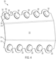
Fig. 4 is front upper perspective view of a stopper holder for use in the system ofFig. 1 ; -
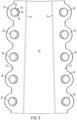
Fig. 5 is a top plan view of the stopper holder ofFig. 4 ; -
Fig. 6 is a right side elevational view of the container tray ofFig. 2 ; -
Fig. 7 is an enlarged fragmentary sectional view of the stopper holder ofFig. 1 , with a stopper secured therein, taken along line 7-7 ofFig. 1 ; -
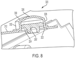
Fig. 8 is a greatly enlarged fragmentary sectional view of the stopper holder ofFig. 7 , without a stopper secured therein, taken along line 7-7 ofFig. 1 ; -
Fig. 9 is an enlarged partial perspective view of a container cell from the container tray ofFig. 2 ; -
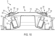
Fig. 10 is a sectional view of the packaging system ofFig. 1 , taken along the line 10-10 inFig. 1 ; -
Figs. 11 and 12 are partial schematic cutaway views showing insertion of a stopper into a vial from a stopper cell as in the packaging system ofFig. 1 ; -
Fig. 13 is a top plan view of an exemplary stopper for use in a packaging system according to the invention; -
Fig. 14 is a side elevational view of the stopper ofFig. 13 ; -
Fig. 15 is a bottom elevational view of the stopper ofFig. 13 ; -
Fig. 16 is a sectional view of the system of stopper 13, taken along the line 16-16 inFig. 13 ; -
Fig. 17 is a perspective view of an exemplary vial for use in packaging systems disclosed herein; -
Fig. 18 is a top front right perspective view of a second embodiment of a packaging system according to the invention; -
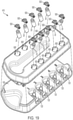
Fig. 19 is a top front right partially exploded view of the packaging system ofFig. 18; -
Fig. 20 is a greatly enlarged partial perspective view of the packaging system ofFig. 18; -
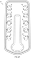
Fig. 21 is a bottom plan view of a shuttle tray for use in the packaging system ofFig. 18 ; -
Fig. 22 is an enlarged, exploded partial perspective view of a shuttle and stopper for use in the packaging system ofFig. 18; -
Fig. 23 is a top perspective view of a shuttle for use in the packaging system ofFig. 18 ; -
Fig. 24 is a side elevational view of the shuttle ofFig. 23 ; -
Fig. 25 is a sectional view of the shuttle ofFig. 23 taken along line 25-25 ofFig. 23 ; -
Fig. 26 is a perspective schematic view of a shuttle containing a stopper removably secured in a shuttle tray in the packaging system ofFig. 18 ; -
Fig. 27 is a perspective schematic view of the shuttle being released from the shuttle tray ofFig. 26 ; -
Fig. 28 is a perspective schematic view of a stopper being inserted into a vial via the tool and the shuttle ofFig. 26 ; -
Fig. 29 is a perspective schematic view of the stopper in the vial ofFig. 28 , with the stopper being released from the shuttle via the tool; -
Fig. 30 is a perspective view of a sterilization bag for use in packaging systems disclosed herein; -
Fig. 31 is a top perspective view of a first embodiment of a shuttle-handling tool for use with the packaging system ofFig. 18 ; -
Fig. 32 is an enlarged, partial perspective view of a stopper-handling tool for use with the packaging systems disclosed herein; -
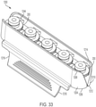
Fig. 33 is an inverted bottom perspective view of a stopper clip according to an embodiment of the invention; -
Fig. 34 is a top perspective view of the stopper clip ofFig. 33 ; -
Figs. 35A and 35B are schematic sectional views showing use of a second embodiment of a stopper clip according to the invention; -
Fig. 36 is a right rear perspective view of a second embodiment of a stopper holder for use in packaging systems disclosed herein; -
Fig. 37 is a sectional view of the stopper holder ofFig. 36 taken along line 37-37 ofFig. 36 ; -
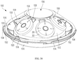
Fig. 38 is a front perspective view of a third embodiment of a stopper handling system ; -
Fig. 39 is a top elevational view of the stopper handling system ofFig. 38 ; and -
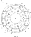
Fig. 40 is a side elevational view of the stopper handling system ofFig. 38 ; -
Fig. 41 is a perspective view of a filling system; -
Fig. 42 is a detail perspective view of the filling system ofFig. 41 ; and -
Fig. 43 is a perspective view of a cover for use with the filling system ofFig. 41 . - Referring to
Figs. 1-17 , a first embodiment of apackaging system 10 includes a medicine container, which is in the illustrated embodiments is a conventional drug vial 20 (seeFig. 17 ) having afill opening 22 and avial flange 23. The packaging system also includes a stopper 200 (Figs. 13-16 ) for sealing the fill opening of thevial 20. The example of astopper 200 shown herein has amajor portion 202 with amajor diameter 204, and aminor portion 206 with aminor diameter 208. Theminor portion 206 has abore 210 and a tapered lower-end portion 212. Many varieties of stoppers are compatible with thevial 20 and thepackaging system 10, including but not limited to a stopper lacking well-defined major and minor portions ofstopper 200 as illustrated herein. As described in more detail hereinafter, thepackaging system 10 preferably comprises asecond vial 20 and asecond stopper 200 and more preferably a plurality ofvials 20 and a plurality ofstoppers 200 for sealing the plurality ofvials 20. - A
container tray 100 preferably includes a plurality ofcontainer cells 120 for receiving and stabilizing a corresponding plurality of thevials 20. Thecontainer tray 100 is preferably constructed of molded polymeric material with thecontainer cells 120 formed therein by the molding process, as best shown inFigs. 2 and3 . Thecontainer tray 100 may aid a user in an assisted-hand-filling operation by stably holding thevials 20 so that the user may conveniently insert astopper 200 into theopening 22 of eachvial 20. As best shown inFig. 9 , eachcontainer cell 120 includes a snap mechanism formed by two sidewallflexible legs 124 and aflexible latch 122 attached to thecontainer cell 120 for releasably securing thevial 20 in thecontainer cell 120. Eachcontainer cell 120 is generally in the form of a truncated trough with anopen end 120a. Each of the twoside wall legs 124 includes achamfered latch 124a at a top end thereof extending radially inwardly with respect to thecontainer cell 120. Thelatch 122 is positioned just inwardly of theopen end 120a. Theside wall legs 124 and latch 122 are positioned triangularly to releasably, slidably, and securely receive thevial 20. Thechamfered latch 124a extends over ashoulder 21 of thevial 20 in a snap-fit manner when thevial 20 is positioned in thecontainer cell 120. - Turning to
Figs. 1 ,4 , and5 , thepackaging system 10 also preferably includes astopper holder 300, which in the illustrated embodiment includes acentral panel 310 and with twoside panels 312 joined thereto by living hinges 314. Each living hinge described herein, including without limitation theliving hinge 314, is preferably a thinned portion of the same material as the two parts joined by the living hinge, in this case theside panels 312. The livinghinge 314 is disposed between the twoside panels 312 to allow pivoting motion therebetween. Alternatively, a stopper holder 300' may have a row of stopper cells 320' arranged linearly in a single, generally planar strip, as shown inFigs. 36 and 37 . The stopper cells 320' may be sealed by adhesive panels 330'. The stopper cells 320' may have minimal side walls, or the side walls may even be eliminated entirely. Thestopper holder 300, 300' is preferably constructed of a molded polymeric material. - Referring again to
Figs. 1-17 , arranged on theside panels 312 is at least onestopper cell 320, and preferably a plurality ofstopper cells 320, which conveniently may be located at regularly spaced intervals. Thestopper holders 320 preferably align with thecontainer cells 120 of thecontainer tray 100. In thestopper holder 300, eachstopper cell 320 may form a generally cylindrically shaped closed body with adistal opening 322, aninterior space 324, a proximalinner surface 326 opposite thedistal opening 322, aside wall 328, a proximalouter surface 330, and a sideouter surface space 332. A proximal wall 325 is formed between the proximal inner andouter surfaces side wall 328 may be formed with a minimal height or eliminated entirely, leaving a stopper cell 320' (seeFigs. 36 and 37 ) that is essentially dome-shaped (i.e., the proximalouter surface 330 would interface with the side panel 312). Thestopper cell 320 releasably secures thestopper 200 therein and is adapted to release thestopper 200 into thefill opening 22 of thevial 20 when a compressive force is exerted on the proximalouter surface 330 of thestopper cell 300. The securing of thestopper 200 preferably occurs through an interference friction fit, preferably a mild interference fit, between thestopper 200 and the sideinner surface 328 of thestopper cell 320. The proximalouter surface 330 of thestopper cell 320 is preferably curved outwardly with respect to theinterior space 324. - The
stopper cell 320 is preferably constructed by thermoforming of a flexible polymer, such as polyethylene or PETG (polyethylene terephthalate glycol-modified, from which at least a portion of the stopper cell 320 (such as the proximal wall 325 and the side wall 328), and thestopper holder 300, may be formed. Alternatively, in an embodiment not shown, thestopper cell 320 may be constructed from a rigid material and have a living hinge along the interface between thestopper cell 320 and theside panel 312 or between theproximal wall 330 and thesidewall 328. Referring particularly toFigs. 11 and 12 , in the embodiment shown, the proximalouter surface 330 of thestopper cell 300 flexes inwardly when the compressive force, such as that which may be applied by afinger tip 331, is exerted thereon, and the proximal wall 325 flexes toward thestopper 200 and exerts a compressive force on thestopper 200 to urge thestopper 200 from thestopper cell 320 and into thefill opening 22 of thevial 20. Thecontainer cells 120 may be configured to releasably secure thevials 20 at an outward angle with respect to thecontainer tray 100. This configuration presents thefill openings 22 at a favorable angle for the user to insert thestoppers 200 into thefill openings 22. - Referring to
Figs. 18-31 , a second embodiment of apackaging system 410 includes a medicine container in the form of one ormore vials 20, thecontainer tray 100, and a corresponding number ofstoppers 200 as described above. A shuttle 500 (Figs. 22-25 ) has anexterior surface 502 and aninterior surface 504. Theinterior surface 504 is configured for releasably gripping thestopper 200. Theshuttle 500 is configured to release thestopper 200 into thefill opening 22 of thevial 20 upon application of a releasing force to theexterior surface 502 of the shuttle 500 (that is, with the user handling theshuttle 500 rather than directly handling the stopper 200) in the manner described below. - The
packaging system 410 also includes ashuttle tray 600 with ashuttle cell 620. More particularly, theshuttle tray 600 preferably has a plurality ofshuttle cells 620, which preferably are arranged at regularly spaced intervals. Theshuttle tray 600 is preferably of a molded polymer material and is stackable upon the container tray 100 (as described above), with theshuttle tray 600 and thecontainer tray 100 accommodating matching quantities ofshuttles 500 andvials 20 or other medicine containers. - Referring to
Figs. 20-21 , eachshuttle cell 620 forms a generally cylindrical closed body with a proximal opening 622, an interior space 624, a bottom inner surface 626 opposite the proximal opening 622, and a sideinner surface 628. Theshuttle cell 620 releasably secures theshuttle 500 therein. One of the bottom inner surface 626 and the sideinner surface 628 of theshuttle cell 620 has alock opening 630 for engaging portions of the shuttle 500 (see below) to secure theshuttle 500 in theshuttle cell 620. - The
exterior surface 502 extends over the various exterior contours and features of theshuttle 500, and theinterior surfaces 504 similarly extend over the various interior contours and features of theshuttle 500. Theshuttle 500 has a generallycylindrical body 501 with aproximal end 508, adistal end 510, first and second distally extendinglegs 512 attached to thebody 501, and distally extendingribs 501a. The first and second distally extendinglegs 512 include transversely extendinglocking mechanisms 514.Notches 506 are located on the exterior surface and theinterior surface 504 extending into the first and second distally extendinglegs 512. Thenotches 506 on the first andsecond legs 512 provide a point of flexion of thelegs 512, allowing thelegs 512 to move more easily to secure and release thestopper 200. The first andsecond legs 512 also include first and second proximally facing stopper supports 512a, which engage themajor portion 202 of thestopper 200 to secure the major portion between the stopper supports 512a and theribs 501a. First and second tool fittings in the form oftool openings 518 are formed in each of the first and second legs 512 (and more particularly in the locking protrusions 514) for releasably engaging a tool, preferably a curved tool 800 (Fig. 31 ) so that a movement of thetool 800 causes deformation of thelegs 512, causing thelegs 512 to flex outwardly and thereby disengage the notches stopper supports 512a from thestopper 200, thereby releasing thestopper 200 from theshuttle 500. Moreover, the first andsecond legs 512 havecurved portions 512b for contacting thevial flange 23 of thevial 20. Distal movement of theshuttle 500 causes thevial flange 23 to press against thecurved portions 512b, aiding in outward flexion of thelegs 512 and thus in release of thestopper 200 from theshuttle 500. The form and operation of thecurved tool 800 are discussed in more detail below. - The locking
protrusions 514 extend radially outwardly, and are configured for engaging thelock openings 630 of theshuttle cell 620 to releasably secure theshuttle 500 in theshuttle cell 620. In the illustrated embodiment, thelock opening 620 is configured so that theshuttle 500 may be placed in theshuttle cell 620 and rotated to engage and disengage the lockingprotrusions 514 from thelock openings 630, thereby securing and releasing theshuttle 500 from theshuttle cell 620. - As discussed in more detail below, the
shuttle 500 enables a user to handle and release thestopper 200 by employing a tool such as thetools exterior surface 502 of theshuttle 500, so that any tool employed by the user does not touch, and therefore does not potentially foul or contaminate, thestopper 200. Theshuttle 500 is configured to release thestopper 200 into thefill opening 22 of avial 20 upon application of a releasing force to theexterior surface 502 of the shuttle. - The
tools Fig. 32 , astraight tool 700 may be used with thepackaging system 410, and generally with the packaging systems disclosed herein, for engaging thestopper 200. Thestraight tool 700 comprises afirst arm 702 having a firstproximal end 704 and a firstdistal end 706 and asecond arm 708 having a secondproximal end 710 and a seconddistal end 712. The firstproximal end 704 and the second proximal 710 end are joined to each other at a proximal joint, which may be a pinned joint but, as shown in the figure, the proximal joint is shown as anintegral formation 714 of the first and second proximal ends 704, 710, such that thetool 700 functions similarly to a tweezer. Thefirst arm 702 has a first-arminterior surface 716 facing thesecond arm 708, a firstgripping surface 718 facing thesecond arm 708, and afirst abutment surface 720 perpendicular to the first gripping surface. The second arm has a second-arminterior surface 722 facing thefirst arm 702, and a second gripping surface and a second abutment surface (not numbered), which are mirror images of the firstgripping surface 718 and thefirst abutment surface 720. The firstgripping surface 718 of thefirst arm 702, and the mirror image thereof on thesecond arm 708, facilitate gripping thestopper 200 by themajor portion 202 to avoid contamination of theminor portion 204. Thegripping surface 718 is preferably curved to match themajor portion 202 of thestopper 200. Thefirst abutment surface 720 of thefirst arm 702, and the mirror image thereof on thesecond arm 708, facilitate pressing thestopper 200 into thefill opening 22 of thevial 20. - Referring to
Fig. 31 , thecurved tool 800 may be used with thepackaging system 410, and generally with the packaging systems disclosed herein, for engaging thetool opening 518 and, where applicable thestopper 200. Thecurved tool 800 includes afirst arm 802 having a firstproximal portion 804. Asecond arm 806 has a secondproximal portion 808. The firstproximal portion 804 and the secondproximal portion 808 are joined to each other at a proximal joint, which in the illustrated embodiment is anintegral formation 810 of the first andsecond arms first arm 802 has a firstdistal end 812 and a firstdistal end portion 814 extending proximally from the firstdistal end 812, a firstinterior surface 815 facing thesecond arm 806, and an opposite firstexterior surface 816, with the firstinterior surface 814 having a firstcurved portion 818 extending convexly towards thesecond arm 806. Thesecond arm 806 has a second distal end 820 and a seconddistal end portion 822 extending proximally from the second distal end 820, a secondinterior surface 821 facing thefirst arm 802, and an opposite secondexterior surface 824, with the secondinterior surface 821 having a secondcurved portion 826 extending convexly toward thefirst arm 802, which faces but is spaced from the frontcurved portion 818. Operation of the first and secondcurved portions tool 800 is expected to generate fewer particulates than other devices for this purpose. Further, thetool 800 can be formed with a single mold, which is an advantage in manufacturing. - In use, the
stopper 200 is preloaded into theshuttle 500 with themajor portion 202 of thestopper 200 located between theribs 501a and the stopper supports 512a of theshuttle 500. The preloading process is done at a manufacturing facility by assembly equipment unrelated to the present disclosure. Theshuttle 500 with thestopper 200 preloaded is then ready for installation using thecurved tool 800 to place thestopper 200 in thefill opening 22 of thevial 20 as described in more detail below. In the initial position, thefirst arm 802 and thesecond arm 806 are aligned and biased so that when no exterior force is applied to thecurved tool 800, the firstdistal end portion 814 and the seconddistal end portion 822 are aligned at a first distal-end-portion distance 828 less than a diameter of the stopper 200 (preferably less than themajor diameter 204 of the stopper), and so that upon application of a first compressive force upon the firstexterior surface 816 and the secondexterior surface 824, the firstcurved portion 818 merely contacts the secondcurved portion 826, which would slightly reduce the first distal-end-portion distance 828. The firstcurved portion 818 and the secondcurved portion 826 are curved in complementary fashion (here as mirror images of one another) so that upon application of a second compressive force greater than the first compressive force upon the firstexterior surface 816 and the secondexterior surface 824, thefirst arm 802 flexes and deforms, and thesecond arm 806 flexes and deforms, such that the firstdistal end portion 814 and the seconddistal end portion 822 move apart to a second distal-end-portion distance 830 (in phantom) greater than the first distal-end-portion distance 828. Thefirst arm 802 and thesecond arm 806 are configured and biased so that upon application of the second compressive force upon the firstexterior surface 816 and the secondexterior surface 824 via thetool openings 518, the first andsecond portions distal end portion 814 and the seconddistal end portion 822 move apart to permit theshuttle 500 to be grasped therebetween. That is, once the first and seconddistal end portions tool openings 518, the second compressive force is released resulting in the first and seconddistal end portions tool openings 518 and thus clamping theshuttle 500 andstopper 200 between the first and seconddistal end portions - The
curved tool 800 can now be used to position thestopper 200 in thefill opening 22 of thevial 20. To release thestopper 200 from theshuttle 500, a fourth compressive force is applied to the firstexterior surface 816 of thefirst arm 802 and the secondexterior surface 824 of thesecond arm 806, the firstdistal end portion 814 and the seconddistal end portion 824 move apart to permit thefirst arm 802 and thesecond arm 806 to engage the radially outward surfaces of the first andsecond tool openings 518 of theshuttle 500 to move the first andsecond legs 512 of theshuttle 500 outwardly to cause the first andsecond notches 506 of the first andsecond legs 512 of theshuttle 500 to release thestopper 200. The firstdistal end portion 814 of thefirst arm 802 has an outwardly facingfirst step 832, and the seconddistal end portion 824 of thesecond arm 806 has an outwardly facing second step 834, for engaging the first andsecond tool openings 518 of theshuttle 500. Theshuttle 500 can then be removed from thecurved tool 800 releasing the first andsecond arms distal end portions tool openings 518. At this point, theshuttle 500 can be reused if desired by returning to the manufacturing facility for reloading astopper 200 or recycled. - Referring to
Figs. 33-35 , a third embodiment of a packaging system also includes a medicine container in the form of the vial 20 (and preferably includes a plurality of vials 20), along with thestopper 200 as described above, and may include acontainer tray 100 as described above. - A
stopper clip 1200 comprises a hinged base having first and second hinged-base legs base leg 1204 having a first proximal hinged-base-leg end 1206 and a first distal hinged-base-leg end 1208, and the second hinged-base leg 1210 having a second proximal hinged-base-leg end 1212 and a second distal hinged-base-leg end 1214, the first and second proximal hinged-base-leg ends 1208, 1214 being joined to each other by ahinge 1216. In an alternative stopper clip 1200', the hinged-base-leg ends 1208, 1214 may be joined by a living hinge 1216' disposed between the first and second hinged-base legs 1204, 1210 (seeFig. 35 ). Referring again toFigs. 33-35 , thehinge 1216, 1216' is biased to urge the first and second distal hinged-base-leg ends 1208, 1214 toward one another to a first position, which is a resting position of thestopper clip 1200 when empty (with nostoppers 200 therein). As shown inFigs. 33 and35 , the hinged-basedlegs legs stopper 200. - The first hinged-
base leg 1204 has afirst lever 1218 extending proximally therefrom, and the second hinged-base leg 1210 has asecond lever 1230 extending proximally therefrom. Thefirst lever 1218 has a firstinterior lever surface 1220 facing thesecond lever 1230 and a firstexterior lever surface 1222 facing opposite the firstinterior lever surface 1220. Thesecond lever 1230 has a secondinterior lever surface 1232 facing thefirst lever 1218 and a secondexterior lever surface 1234 facing opposite the secondinterior lever surface 1232. - The
first lever 1218 and thesecond lever 1230 are in spaced relation and operate in the manner of a clothes pin or clip such that, upon the application of a first compressive force to the firstexterior lever surface 1222 and the secondexterior lever surface 1234, the first hinged-base leg 1204 and the second hinged-base leg 1210 are urged to a second position, with the first and second hinged-base legs stoppers 200 between the first and second hinged-base legs Fig. 35B . - The first hinged-
base leg 1204 has a first pushingsurface 1240 adapted to make contact with theproximal end surface 214 of thestopper 200 when thestopper 200 is secured between the first and second hinged-base legs stopper 200 is aligned with thefill opening 22 of thevial 20, and thestopper clip 1200 is urged distally to urge thestopper 200 into thefill opening 22. Similarly, the second hinged-base leg 1210 has a second pushingsurface 1242 adapted to make contact with theproximal end surface 214 of the stopper when thestopper 200 is secured between the first and second hinged-base legs stopper 200 is aligned with thefill opening 22 of thevial 20, and thestopper clip 1200 is urged distally to urge thestopper 200 into thefill opening 22. The first hinged-base leg 1204 has afirst retention arm 1244 projecting toward the second hinged-base leg 1210, and the second hinged-base leg 1210 has asecond retention arm 1246 projecting toward the first hinged-base leg 1204. Upon removal of the first compressive force, the first and second hinged-base legs base legs stopper 200 therebetween (Figs. 33 ,35A ). - The
first retention arm 1244, 1244' and thesecond retention arm 1246, 1246' are configured and aligned to create aretention gap 1250, 1250' (seeFig. 33A ) therebetween, a dimension of theretention gap 1250, 1250' being smaller than themajor diameter 204 of thestopper 200 and greater than or equal to theminor diameter 208 of thestopper 200. Thefirst retention arm 1244, 1244' and thesecond retention arm 1246, 1246' together support thestopper 200 to prevent distal movement of thestopper 200 when thestopper 200 is secured between the first and second hinged-base legs - Preferably the
stopper clip 1200, 1200' is used with a container tray having a plurality of container cells similar to that described above inFigs. 1-17 . The use of thestopper clip 1200 allows the simultaneous gripping and insertion of a plurality ofstoppers 200 into a corresponding plurality ofvials 20, by manipulating the first andsecond levers - Referring to
Figs. 38-40 , a system for handling stoppers for medication containers includes a plurality ofstoppers 200 as described above. A handlingtray 1500 includes abase 1510, a plurality of stopper rests 1520 disposed upon thebase 1510 for releasably securing the plurality ofstoppers 200 to thebase 1510. Thebase 1510 has anupper surface 1512 and alower support surface 1514. Theupper surface 1512 is spaced from and angled upwardly with respect to thelower support surface 1514 in the form of a cone for convenient access to thestoppers 200. - A
transparent cover 1550 is releasably and sealingly connected to thebase 1510 for covering thestoppers 200. Thecover 1550 has a cover-flange perimeter 1552 and a plurality of spaced and outwardly extendingcircumferential cover flanges 1554 extending therefrom. Thecover 1510 may include a disinfectant-permeable panel 1556 for sterilization of the contents of thehandling tray 1500. Thebase 1510 has an outwardly extendingcircumferential base flange 1516 extending therefrom, and thebase flange 1516 in turn has a plurality of spaced and upwardly extending cover-retaining walls 1518 extending therefrom. The cover-retaining walls 1518 form a plurality of cover-retaininggaps 1519 therebetween used for removing thecover 1550. The cover-retaining walls 1518 and thebase flanges 1516 of thebase 1510 are spaced such that in a first position thecover 1550 is supported upon thebase flange 1510 with thecover flanges 1554 being supported in the cover-retaininggaps 1519. In a second rotated position, thecover flanges 1554 are aligned with and in contact with the cover-retaining walls 1518 of the base 1510 to releasably secure thecover 1550 to thebase 1510. In an alternative embodiment (not shown), thecover 1550 may be threadedly attached to thebase 1510 or may be unthreaded and may mate in an interference fit with thebase 1510; in either case, thebase flange 1516, the cover-retaining walls 1518, and thecover retaining gaps 1519 may be omitted. - The stopper rests 1520 are arranged such that the stoppers 200 (
Figs. 13-16 ) are in spaced relation to one another. Eachstopper rest 1520 comprises adepression 1522 having a stopper-rest opening 1524 in theupper surface 1512 communicating with a stopper-rest bottom surface 1526, the stopper-rest opening 1524 being shaped so that theminor portion 206 of thestopper 200 passes through the stopper-rest opening 1524, while themajor portion 202 of thestopper 200 does not pass through the stopper-rest opening 1524. The stopper-rest opening 1524 also has avent 1528 communicating between the stopper-cell bottom surface 1526 and avolume 1530 above theupper surface 1512 of thebase 1510 for at least sterilization purposes. In addition, thevent 1528 may also allow air/gas to displace from thedepression 1522 when astopper 200 is inserted therein. A column extends upwardly from the stopper-rest bottom surface 1526 and is positioned within the bore 210 (Figs. 13-16 ) of thestopper 200 to assist with aligning the stopper in the stopper-rest opening 1524. - Referring to
Figs. 41-43 , analternative filling system 1010 includes thecontainer tray 100 and astopper tray 1300 with acover 1400. Thestopper tray 1300 and thecover 1400 are preferably constructed of a molded polymeric material. Arranged on thestopper tray 1300 is at least onestopper carrier 1302, and preferably a plurality ofstopper carriers 1302, which conveniently may be placed at regularly spaced intervals. Thestopper carriers 1302 preferably correspond in number to and are alignable with thecontainer cells 120 of thecontainer tray 100. In thestopper tray 1300, eachstopper carrier 1302 includes a generally cylindrically shaped closed body with aproximal opening 1322, aninterior space 1324, a distalinner surface 1326 opposite theproximal opening 1322, and aside wall 1328. Theproximal opening 1322 may be disposed within a stopper-carrier notch 1340 in atop surface 1342 of thestopper carrier 1302. Thestopper carrier 1302 includes at least one stopper-locating surface, which in the illustrated embodiment comprises fourfree end surfaces 1330a of four stopper-support extensions 1330, which extend radially inwardly from theside wall 1328 and upwardly from the distalinner surface 1326. Thefree end surfaces 1330a may be configured to engage aminor portion 206 of astopper 200, with amajor portion 204 of thestopper 200 supported on the stopper-support bodies 1330. Thetop surface 1342 of thestopper tray 1300 has downwardly extendingbores 1332. Thecover 1400 secures to thestopper tray 1300 to secure thestoppers 200 in thestopper tray 1300 during shipment and prior to use. Thecover 1400 has anupper surface 1401 and downwardly extending boss features 1402 for engaging and being positioned within the downwardly extending complementarysized bores 1332 of thestopper tray 1300 to secure thecover 1400 to thestopper tray 1300, and downwardly extending stopper-carrier covers 1404, which align with and extend into thestopper carriers 1302 to secure thestoppers 200 to thestopper tray 1300. - Referring to
Fig. 30 , asterilization bag 900 may be provided containing any or all of the components of any of the packaging systems disclosed herein. Thesterilization bag 900 preferably may be a material permeable to a disinfectant (for example, steam) while being impermeable to contaminants. Thesterilization bag 900 may be used to sterilize the packaging system after manufacture or before use and may serve as disposable packaging in which the packaging system may be provided to the user. - It is understood, therefore, that this invention is not limited to the particular embodiments disclosed, but it is intended to cover modifications within the scope of the present invention as defined by the appended claims.
- In addition, certain terminology is used in the following description for convenience only and is not limiting. The words "lower," "bottom," "upper," "top," "front," "back," and "rear" designate directions in the drawings to which reference is made. The words "inwardly" and "outwardly" refer to directions toward and away from, respectively, the geometric center of the component being discussed, and designated parts thereof, in accordance with the present disclosure. Unless specifically set forth herein, the terms "a," "an," and "the" are not limited to one element, but instead should be read as meaning "at least one." "At least one" may occasionally be used for clarity or readability, but such use does not change the interpretation of "a," "an," and "the." The terminology includes the words noted above, derivatives thereof, and words of similar import Moreover, the singular includes the plural, and vice versa, unless the context clearly indicates otherwise. Various components are described in terms of a single component; however, the illustrated embodiment, or other embodiments not illustrated, may include two or more of the same component, as illustrated in the drawings or noted in the specification, or as otherwise would be understood by a person of skill in the art. Various components are described as being secured against movement or flexing; these references do not contemplate the absolute elimination of all movement or flexing. Instead, these references include restriction or movement of flexing sufficient to alter the functionality of the component or components in operative relation therewith. References to a component extending, moving, or flexing in a particular direction refer to the component extending, moving, or flexing at least partially in the particular direction; an extension, movement, or flexion that includes any component of movement in the particular direction is included.
Claims (16)
- A packaging system (10) for filling and sealing with a stopper (200) at least one medicine container (20) having a fill opening (22), the packaging system (10) comprising:a container tray (100) having a container cell (120) for receiving and stabilizing the medicine container (20); anda stopper holder (300) with a stopper cell (320), the stopper cell (320) forming a closed body with a distal opening (322), an interior space (324), a proximal inner surface (326) oppositethe distal opening (322), and a proximal outer surface (330), the stopper cell (320) configured for releasably securing the stopper (200), the stopper cell (320) being adapted to release the stopper (200) into the fill opening (22) of the medicine container (20) when a compressive force is exerted on the proximal outer surface (330) of the stopper cell (320);characterized in that the stopper cell (320) comprises a flexible material, and the proximal outer surface (330) of the stopper cell (320) flexes inwardly when the compressive force is exerted thereon, and the proximal inner surface (326) flexes towardthe stopper (200) and exerts a compressive force on the stopper (200) to urge the stopper (200) from the stopper cell (320) and into the fill opening (22) of the medicine container (20).
- The packaging system (10) of claim 1, wherein an inner surface (328) of the stopper cell (320) has an interference fit with the stopper (200).
- The packaging system (10) of claim 1, wherein the proximal outer surface (330) of the stopper cell (320) is curved outwardly with respect to the interior space (324).
- The packaging system (10) of claim 1, wherein the container tray (100) comprises a plurality of container cells (120) for releasably securing a plurality of medicine containers (20), and
the stopper holder (300) comprises a plurality of stopper cells (320) and is configured to align at least some stopper cells (320) of the plurality of stopper cells (320) with at least some container cells (120) of the plurality of container cells (120). - The packaging system (10) of claim 1 wherein each container cell (120) includes a snap mechanism formed by a plurality of flexible legs (124) attached to the container cell (120) for releasably securing the medicine container (20) in the container cell (120).
- A packaging system (410) for filling and sealing with a stopper (200) at least one medicine container (20) having a fill opening (22), the packaging system (410) comprising:a container tray (100) having a container cell (120) for receiving and stabilizing the medicine container (20);a shuttle (500) having an exterior surface (502) and an interior surface (504), the interior surface (504) being configured for releasably securing the stopper (200), the shuttle (500) being configured to release the stopper (200) into the fill opening (22) upon application of a releasing force to the exterior surface (502) of the shuttle (500); anda shuttle tray (600) with a shuttle cell (620), the shuttle cell (620) forming a closed body with a proximal opening (622), an interior space (624), a bottom inner surface (626) opposite the proximal opening (622), and a side inner surface (628), the shuttle cell (620) releasably securing the shuttle (500).
- The packaging system (410) according to claim 6, wherein the shuttle (500) has a body (501) with a proximal end (508), a distal end (510), and first and second distally extending legs (512) attached to the body (501), the first leg (512) having a first stopper fitting (512a) attached thereto for releasably securing the stopper (200) to the shuttle (500) and a first tool fitting (518) attached thereto for releasably engaging a tool (800) so that a movement of the tool (800) causes a first deformation of the first leg (512), the second leg (512) having a second stopper fitting (512a) attached thereto for releasably securing the stopper to the shuttle (500) and a second tool fitting (518) attached thereto for releasably engaging the tool (800) so that a movement of the tool (800) causes a second deformation of the second leg (512), the first deformation and the second deformation causing the first stopper fitting (512a) and the second stopper fitting (512a) to release the stopper (200).
- The packaging system (410) according to claim 7, whereinthe first leg (512) has a first locking protrusion (514) extending radially outwardly, the second leg (512) has a second locking protrusion (514) extending radially outwardly, andone of the bottom inner surface (626) and the side inner surface (628) of the shuttle cell (620) has a lock opening (630) for engaging the locking protrusions (514) of the legs (512) to releasably secure the shuttle (500) in the shuttle cell (620).
- The packaging system (410) according to claim 7, further comprising:a tool (800) for engaging the tool fittings (518), the tool (800) comprising:a first arm (802) having a first proximal portion (804) and a second arm (806) having a second proximal portion (808), the first proximal portion (804) and the second proximal portion (808) being joined to each other at a proximal joint (810),the first arm (802) having a first distal end (812) and a first distal end portion (814) extending proximally from the first distal end (812), a first interior surface (815) facing the second arm (806), and an opposite first exterior surface (816), with the first interior surface (815) having a first curved portion (818),the second arm (806) having a second distal end (820) and a second distal end portion (822) extending proximally from the second distal end (820), a second interior surface (821) facing the first arm (802), and an opposite second exterior surface (824), with the second interior surface (821) having a second curved portion (826),the first arm (802) and the second arm (806) being aligned and biased so that when no exterior force is applied to the tool (800), the first distal end portion (814) and the second distal end portion (822) are aligned at a first distal-end-portion distance (828) less than a diameter of the stopper (200), and so that upon application of a first compressive force upon the first exterior surface (816) and the second exterior surface (824), the first curved portion (818) contacts the second curved portion (826),the first curved portion (818) and the second curved portion (826) being curved so that upon application of a second compressive force greater than the first compressive force upon the first exterior surface (816) and the second exterior surface (824), the first arm (802) flexes and deforms, and the second arm (806) flexes and deforms, such that the first distal end portion (814) and the second distal end portion (822) move apart to a second distal-end-portion distance (830) greater than the first distal-end-portion distance (828), andthe first arm (802) and the second arm (806) are configured and biased so that upon application of the second compressive force upon the first exterior surface (816) and the second exterior surface (824), the first distal end portion (814) and the second distal end portion (822) move apart to permit the shuttle (500) to be grasped therebetween, with the first arm (802) and the second arm (806) being biased so that upon the application of a third compressive force upon the first exterior surface (816) and the second exterior surface (824), the first distal end portion (814) and the second distal end portion (822) engage the exterior surface (502) of the shuttle (500) to releasably secure the shuttle (500) between the first arm (802) and the second arm (806).
- The packaging system (410) according to claim 7, whereinthe tool fitting (518) of the first leg (512) comprises a first body protruding outwardly from the first leg (512) and having a first tool aperture therein and the tool fitting (518) (518) of the second leg (512) comprises a second body protruding outwardly from the second leg (512) and having a second tool aperture therein,the first arm (802) and the second arm (806) of the tool (800) are configured and aligned so that upon application of a fourth compressive force upon the first exterior surface (816) of the first arm (802) and the second exterior surface (824) of the second arm (806), the first distal end portion (814) and the second distal end portion (822) move apart to permit the first arm (802) and the second arm (806) to engage the first tool aperture and the second tool aperture to move the first leg (512) and the second leg (512) of the shuttle (500) outwardly to cause the first and second stopper fittings (512a) of the first and second legs (512) of the shuttle (500) to release the stopper (200).
- The packaging system (410) according to claim 10, wherein
the first distal end portion (814) of the first arm (802) has an outwardly facing first step (832) for engaging the first tool aperture, and the second distal end portion (822) of the second arm (806) has an outwardly facing second step (834) for engaging the second tool aperture. - A packaging system (10) for filling and sealing with a stopper (200) at least one medicine container (20) having a fill opening (22), the packaging system comprising:a container tray (100) having a container cell (120) for receiving and stabilizing the medicine container (20); anda stopper clip (1200) with a stopper cell , the stopper cell comprising ahinged base having first and second hinged-base legs (1204, 1210), the first hinged-base leg (1204) having a first proximal hinged-base-leg end (1206) and a first distal hinged-base-leg end (1208), and the second hinged-base leg (1210) having a second proximal hinged-base-leg end (1212) and a second distal hinged-base-leg end (1214), the first andsecond proximal hinged-base-leg ends (1206, 1212) being joined to each other by a hinge (1216; 1216'), the hinge (1216; 1216') being biased to urge the first and second distal hinged-base-leg ends (1208, 1214) toward one another to a first position;the first hinged-base leg (1204) having a first lever (1218) extending proximally therefrom;the second hinged-base leg (1210) having a second lever (1230) extending proximally therefrom;the first lever (1218) having a first interior lever surface (1220) facing the second lever (1230) and a first exterior lever surface (1222) facing opposite the first interior lever surface (1220);the second lever (1230) having a second interior lever surface (1232) facing the first lever (1218) and a second exterior lever surface (1234) facing opposite the second interior lever surface (1232);the first lever (1218) and the second lever (1230) being in spaced relation such that, upon the application of a first compressive force to the first exterior lever surface (1222) and the second exterior lever surface (1232), the first base leg (1204) and the second base leg (1210) are urged to a second position, with the first and second hinged-base legs (1204, 1210) being spaced apart to allow insertion of the stopper (200) between the first and second hinged-base legs (1204, 1210) to be releasably secured therebetween, and upon removal of the first compressive force, the first and second hinged-base legs (1204, 1210) are urged to a third position to releasably secure the stopper (200) therebetween.
- The packaging system according to claim 12, wherein the hinge comprises a living hinge (1216') disposed between the first and second hinged-base legs (1204, 1210).
- The packaging system according to claim 12, whereinthe stopper (200) has a major portion with a major diameter (204), a minor portion with a minor diameter (208), and a proximal surface (214);the first hinged-base leg (1204) has a first pushing surface (1240) adapted to make contact with the proximal end surface (204) of the stopper (200) when the stopper (200) is secured between the first and second hinged-base legs (1204, 1210), the stopper (200) is aligned with the fill opening (22) of the medicine container (20), and the stopper clip (1200) is urged distally to urge the stopper (200) into the fill opening (22); andthe second hinged-base leg (1210) has a second pushing surface (1242) adapted make contact with the proximal end surface (214) of the stopper (200) when the stopper (200) is secured between the first and second hinged-base legs (1204, 1210), the stopper (200) is aligned with the fill opening (22) of the medicine container (20), and the stopper clip (1200) is urged distally to urge the stopper (200) into the fill opening (22);the first hinged-base leg (1204) has a first retention arm (1244; 1244') projecting toward the second hinged-base leg (1210);the second hinged-base leg (1210) has a second retention arm (1246; 1246') projecting toward the first hinged-base leg (1204); andthe first retention arm (1244; 1244') and the second retention arm (1246; 1246') are configured and aligned to create a retention gap (1250; 1250') therebetween, a dimension of the retention gap (1250; 1250') being smaller than the major diameter (204) of the stopper (200) and greater than or equal to the minor diameter (208) of the stopper (200), so that the first retention arm (1244; 1244') and the second retention arm (1246; 1246') together support the stopper (200) to prevent distal movement of the stopper (200) when the stopper (200) is secured between the first and second hinged-base legs (1204, 1210) in the second position.
- The packaging system according to claim 12, further comprising:a second medicine container (20) and a second stopper (200);a container tray (100) comprising a plurality of container cells (120) for releasably securing a plurality of medicine containers (20);wherein the stopper clip (1200) comprises a plurality of stopper cells (320) and is configured to align at least two stopper cells of the plurality of stopper cells (320) with at least two container cells of the plurality of container cells (120);the stopper cells (320) are aligned, with the first hinged-base legs (1204) being mutually aligned and attached and the second hinged-base legs (1210) being mutually aligned and attached, the first levers of the stopper cells being mutually aligned and attached, and the second levers of the stopper cells being mutually aligned and attached, the first and second proximal hinged-base-leg ends (1206, 1212) being joined to each other by a hinge (1216; 1216'), the hinge (1216; 1216') being biased to urge the attached first and second distal hinged-base-leg ends (1208, 1214) toward one another to a first position;the first and second hinged-base legs (1204; 1210) being biased to move in unison to the first position, and upon application of a first compressive force to the first and second levers, the first hinged-based legs (1204) and the second hinged-base legs (1210) move in unison to the second position, and upon removal of the first compressive force, the first hinged-base legs (1204) and the second hinged-base legs (1210) move in unison to the third position.
- The packaging system according to claim 15, wherein the hinge is a living hinge (1216').
Priority Applications (1)
| Application Number | Priority Date | Filing Date | Title |
|---|---|---|---|
| EP22159212.4A EP4026779A3 (en) | 2017-12-22 | 2018-12-24 | Packaging system for small-volume aseptic filling |
Applications Claiming Priority (3)
| Application Number | Priority Date | Filing Date | Title |
|---|---|---|---|
| US201762609758P | 2017-12-22 | 2017-12-22 | |
| US201862712635P | 2018-07-31 | 2018-07-31 | |
| PCT/US2018/067450 WO2019126827A1 (en) | 2017-12-22 | 2018-12-24 | Packaging system for aseptic filling of small volume vials |
Related Child Applications (1)
| Application Number | Title | Priority Date | Filing Date |
|---|---|---|---|
| EP22159212.4A Division EP4026779A3 (en) | 2017-12-22 | 2018-12-24 | Packaging system for small-volume aseptic filling |
Publications (2)
| Publication Number | Publication Date |
|---|---|
| EP3728062A1 EP3728062A1 (en) | 2020-10-28 |
| EP3728062B1 true EP3728062B1 (en) | 2022-03-02 |
Family
ID=65139213
Family Applications (2)
| Application Number | Title | Priority Date | Filing Date |
|---|---|---|---|
| EP22159212.4A Pending EP4026779A3 (en) | 2017-12-22 | 2018-12-24 | Packaging system for small-volume aseptic filling |
| EP18837072.0A Active EP3728062B1 (en) | 2017-12-22 | 2018-12-24 | Packaging system for aseptic filling of small volume vials |
Family Applications Before (1)
| Application Number | Title | Priority Date | Filing Date |
|---|---|---|---|
| EP22159212.4A Pending EP4026779A3 (en) | 2017-12-22 | 2018-12-24 | Packaging system for small-volume aseptic filling |
Country Status (5)
| Country | Link |
|---|---|
| US (4) | US11161633B2 (en) |
| EP (2) | EP4026779A3 (en) |
| JP (1) | JP6799719B1 (en) |
| CN (2) | CN111655593B (en) |
| WO (1) | WO2019126827A1 (en) |
Families Citing this family (6)
| Publication number | Priority date | Publication date | Assignee | Title |
|---|---|---|---|---|
| US12515832B2 (en) * | 2013-08-16 | 2026-01-06 | Vanrx Pharmasystems Inc. | Method, device and system for filling pharmaceutical containers |
| US11199028B2 (en) * | 2016-06-23 | 2021-12-14 | Landis+Gyr Innovations, Inc. | Utility meter enclosure with dual position locks |
| DE102020131098A1 (en) | 2020-11-24 | 2022-05-25 | Syntegon Technology Gmbh | Device for closing pharmaceutical containers |
| JP7498867B2 (en) * | 2020-12-28 | 2024-06-12 | ウエスト ファーマスーティカル サービシーズ インコーポレイテッド | Sterile packaging of vials and their closures using trays |
| AU2023228702A1 (en) * | 2022-03-02 | 2024-09-05 | Medisca Pharmaceutique Inc. | Methods and assemblies for packaging containers for compositions containing active ingredients |
| JP2026514379A (en) * | 2023-03-31 | 2026-05-11 | エーエスピー ヘルス インク. | Sample vial consumables for cell pathology |
Family Cites Families (118)
| Publication number | Priority date | Publication date | Assignee | Title |
|---|---|---|---|---|
| US1155119A (en) * | 1908-10-20 | 1915-09-28 | Star Seal Company | Machine for applying bottle-seals. |
| US2484043A (en) * | 1945-11-26 | 1949-10-11 | Jarly C Malen | Pulling and pushing device |
| US2616600A (en) * | 1948-12-15 | 1952-11-04 | American Seating Co | Bottle carrier |
| US2849848A (en) * | 1953-12-07 | 1958-09-02 | West Co | Stopper-applying machines |
| US2998686A (en) * | 1957-01-10 | 1961-09-05 | Pirro Raffaele | Apparatus for the closure under high vacuum of glass bottles and small bottles |
| US3071274A (en) * | 1961-04-04 | 1963-01-01 | West Co | Cap structure for bottles |
| US3175695A (en) * | 1961-06-15 | 1965-03-30 | Advance Scient Corp | Tissue culture tube rack means |
| US3208617A (en) * | 1964-10-12 | 1965-09-28 | Robert R Baron | Container closure means |
| US3339772A (en) * | 1964-11-16 | 1967-09-05 | Formold Plastics Inc | Container cap |
| FR2049252A5 (en) * | 1969-06-04 | 1971-03-26 | Liege Ste Fse Du | |
| US3649462A (en) * | 1969-11-05 | 1972-03-14 | Nasa | Variable angle tube holder |
| JPS5322156B2 (en) * | 1975-01-07 | 1978-07-06 | ||
| US4098053A (en) * | 1977-05-31 | 1978-07-04 | Stauffer Chemical Company | Automatic container capping apparatus |
| US4164964A (en) * | 1977-10-31 | 1979-08-21 | Shirley D. Alderman | Fluid dispenser for reconstituting beverages and the like |
| US4230231A (en) * | 1979-04-16 | 1980-10-28 | Coulter Electronics, Inc. | Closure cap |
| SE421609B (en) * | 1979-09-05 | 1982-01-18 | Tillander B S R | CORK MOUNTING APPLIANCE WHICH CAN ALSO BE USED FOR COVER OR FILM MOUNTING |
| FR2510514A1 (en) * | 1981-07-31 | 1983-02-04 | Stirnweiss Charles | Feed to fill flasks with gas - has sealed sliding drawer with ports in it to evacuate flasks and fill them with gas before stoppering |
| US4442735A (en) * | 1982-11-24 | 1984-04-17 | Allan Chance | Champagne cork puller |
| FR2571349B1 (en) * | 1984-10-09 | 1986-11-21 | Gallay Sa | METHOD AND DEVICE FOR PLACING MOUTHPIECES BY ELASTIC NESTING |
| JPS61189457A (en) * | 1985-02-19 | 1986-08-23 | Nippon Kokan Kk <Nkk> | Robot hand for automatic industrial analysis of coal or the like |
| US4798106A (en) * | 1986-12-12 | 1989-01-17 | Foster Milton E | Champagne bottle cork puller and inserting apparatus |
| DE3715175C1 (en) * | 1987-05-07 | 1988-11-24 | Pohl Metall Kunststoff | Cap for infusion and transfusion bottles |
| US5005721A (en) * | 1987-05-08 | 1991-04-09 | Abbott Laboratories | Vial seal |
| FR2624615B1 (en) * | 1987-12-11 | 1990-08-03 | Melet Schloesing Lab | DEVICE FOR PRESENTING CONTAINERS |
| DE4021836C1 (en) * | 1990-07-09 | 1991-05-02 | Arzneimittel Gmbh Apotheker Vetter & Co Ravensburg, 7980 Ravensburg, De | |
| US5085332B1 (en) * | 1991-04-11 | 1994-04-05 | Gettig Technologies Inc | Closure assembly |
| DE4135470C2 (en) * | 1991-10-28 | 1993-09-30 | Fes Kunststoff Gmbh | Plastic closure cap, in particular for glass containers in various fields of application |
| US5525298A (en) * | 1991-04-19 | 1996-06-11 | Olympus Optical Co., Ltd. | Apparatus for taking liquid content for use in analysis out of container |
| US5112574A (en) * | 1991-04-26 | 1992-05-12 | Imanigation, Ltd. | Multititer stopper array for multititer plate or tray |
| AU671478B2 (en) * | 1992-08-19 | 1996-08-29 | British Nuclear Fuels Plc | Apparatus for dispensing substances which are biologically hazardous |
| US5275070A (en) * | 1993-04-16 | 1994-01-04 | St Denis Andrew R | Device for removing wine bottle stopper |
| JPH06324051A (en) * | 1993-05-11 | 1994-11-25 | Olympus Optical Co Ltd | Plug opener |
| CA2129299C (en) | 1993-08-19 | 2000-04-04 | William N. Weaver | Container package with composite carrier |
| DE4425277A1 (en) * | 1994-07-16 | 1996-01-18 | Boehringer Mannheim Gmbh | Packaging system for liquid reagents |
| US5494087A (en) * | 1994-10-13 | 1996-02-27 | Pitelka; Karen J. | Apparatus for aiding in the preparation of an injection serum |
| US5519984A (en) * | 1995-03-16 | 1996-05-28 | Mallinckrodt Medical, Inc. | Methods for packaging a pressure or vacuum sensitive product |
| US5685845A (en) * | 1995-07-11 | 1997-11-11 | Becton, Dickinson And Company | Sterile resealable vial connector assembly |
| WO1997003790A1 (en) * | 1995-07-14 | 1997-02-06 | The West Company, Incorporated | Method and apparatus for applying two-piece closure to vial |
| US5655806A (en) * | 1995-11-01 | 1997-08-12 | Halladay; James J. | Tongs with tapered jaws |
| DE29518548U1 (en) * | 1995-11-22 | 1996-02-15 | EFL-Entwicklung und Service für Labortechnik GmbH, 77933 Lahr | Gripper |
| USD386215S (en) * | 1996-03-06 | 1997-11-11 | Temtec | Badge clip |
| US5901866A (en) * | 1998-02-13 | 1999-05-11 | Comar Inc. | Break away overcap |
| DE29703993U1 (en) * | 1997-03-05 | 1998-07-16 | Robert Bosch Gmbh, 70469 Stuttgart | Evacuation and sealing device for small containers with sealing plugs |
| FR2768066B1 (en) * | 1997-09-08 | 1999-11-26 | Gilson Sa | RACK FOR MULTI-CHANNEL PIPETTE CONES |
| US6681475B2 (en) * | 1998-04-20 | 2004-01-27 | Becton Dickinson And Company | Method of sealing a medical container with a plastic closure |
| US6106783A (en) * | 1998-06-30 | 2000-08-22 | Microliter Analytical Supplies, Inc. | Microplate assembly and closure |
| JP4542270B2 (en) * | 1999-02-11 | 2010-09-08 | ソウワード リミテッド | Centrifuge rotor |
| US6594552B1 (en) * | 1999-04-07 | 2003-07-15 | Intuitive Surgical, Inc. | Grip strength with tactile feedback for robotic surgery |
| GB9911609D0 (en) * | 1999-05-20 | 1999-07-21 | Advanced Biotech Ltd | Improved multi-well plates |
| US6263761B1 (en) * | 2000-02-16 | 2001-07-24 | John C. Ryder | Pill bottle opener |
| DE10007367A1 (en) * | 2000-02-18 | 2001-08-23 | Helvoet Pharma | Cap unit for infusion and transfusion bottles comprises plastic lid with radial planned break lines which run into circumferential weakening zone running concentrically around the lid center point |
| US6387078B1 (en) | 2000-12-21 | 2002-05-14 | Gillespie, Iii Richard D. | Automatic mixing and injecting apparatus |
| US6890488B2 (en) * | 2001-06-22 | 2005-05-10 | Matrix Technologies, Inc. | Apparatus for sealing test tubes and the like |
| US6802802B2 (en) * | 2002-05-17 | 2004-10-12 | Usi International, Inc. | Beverage carrier |
| WO2003097239A1 (en) * | 2002-05-17 | 2003-11-27 | Gen-Probe Incorporated | Sample carrier having releasable locking mechanism |
| RU2379217C2 (en) | 2002-09-03 | 2010-01-20 | Медикал Инстилл Текнолоджис, Инк. | Vial assembly to store substance (versions), device assembly containing said vial and method for filling vial |
| ES2232269B1 (en) * | 2003-01-21 | 2006-03-01 | Grifols, S.A. | PROCEDURE FOR THE STERILE DOSAGE OF ROADS. |
| US20050050998A1 (en) * | 2003-05-15 | 2005-03-10 | Reynolds Richard Allen | Bottle cork removal and installation tool |
| US7845505B2 (en) * | 2003-06-03 | 2010-12-07 | Taisei Kako Co., Ltd. | Container cap |
| AT500459B1 (en) | 2004-01-23 | 2010-08-15 | Greiner Bio One Gmbh | METHOD FOR ASSEMBLING A CAP WITH A RECEIVING CONTAINER |
| US7096896B2 (en) * | 2004-03-05 | 2006-08-29 | Medical Instill Technologies, Inc. | Apparatus and method for needle filling and laser resealing |
| US20090026099A1 (en) * | 2004-04-16 | 2009-01-29 | Bottles Of Australia Pty Limited | Beverage Container Carrier |
| DE102004035061A1 (en) * | 2004-07-20 | 2006-02-16 | Bausch + Ströbel Maschinenfabrik Ilshofen GmbH + Co. KG | Device for filling an injection body with a liquid comprises a weighing unit having a lifting mechanism for lifting the injection body from its seat in the carrier plate |
| US8770399B2 (en) * | 2005-10-25 | 2014-07-08 | Per Hjalmarsson | Two-compartment container |
| GB0605238D0 (en) * | 2006-03-15 | 2006-04-26 | Bausch & Lomb | Packaging foil stacking system |
| FR2904114B1 (en) | 2006-07-21 | 2008-10-17 | Biocode Hycel France Sa Sa | CARTRIDGE FOR REACTIVE PRODUCTS FOR USE IN ANALYTICAL APPARATUSES, CARRIER FOR RECEIVING THIS CARTRIDGE, AND ANALYSIS ASSEMBLY COMPRISING SAID CARTRIDGE AND HOLDER |
| AT504573B1 (en) | 2006-12-04 | 2010-09-15 | Ebewe Pharma Gmbh Nfg Kg | PACKING FOR SMALL VOLUME BOTTLES |
| DE102006059952B3 (en) * | 2006-12-19 | 2008-06-19 | Deutsches Zentrum für Luft- und Raumfahrt e.V. | robot structure |
| WO2008109888A1 (en) * | 2007-03-08 | 2008-09-12 | Lendell Manufacturing, Inc. | Plug insertion device and method |
| US20100031760A1 (en) * | 2007-07-03 | 2010-02-11 | Yury Sherman | System for transferance of test tubes from tube rack to centrifuge rotor |
| DE102007042218A1 (en) * | 2007-09-05 | 2009-03-12 | Robert Bosch Gmbh | Method and device for sterile or aseptic handling of containers |
| SG142316A1 (en) * | 2008-04-22 | 2009-11-26 | Illinois Tool Works | Powered grip clamping force |
| EP2282212B1 (en) * | 2008-05-22 | 2018-11-28 | Hitachi High-Technologies Corporation | System for pretreating sample |
| WO2010062602A1 (en) * | 2008-10-28 | 2010-06-03 | West Pharmaceutical Services, Inc. | Syringe piston nest for the manufacture of pre filled syringe |
| EP2191942A1 (en) * | 2008-11-26 | 2010-06-02 | F. Hoffmann-Roche AG | Multi-handling tool |
| US9073649B2 (en) | 2009-08-10 | 2015-07-07 | West Pharmaceutical Services, Inc. | Finger grip for a flangeless container |
| US20110131933A1 (en) | 2009-11-17 | 2011-06-09 | Livingston Darren D | Pressurized capping apparatus |
| WO2011072194A2 (en) * | 2009-12-10 | 2011-06-16 | Pounch Pac Innovations, Llc | Method and machine for filling a flexible pouch having a fitment |
| FR2955563B1 (en) * | 2010-01-26 | 2013-09-06 | Spc France | MACHINE FOR FILLING A PLURALITY OF CONTAINERS, SYSTEM INCLUDING SUCH A MACHINE AND PROCESS FOR PRODUCING THE SAME |
| DE102010009415A1 (en) * | 2010-02-26 | 2011-09-01 | Walter Lindner | Packaging and transport system for glass stopper |
| US20110253251A1 (en) * | 2010-04-15 | 2011-10-20 | Allergan, Inc. | Needle guide |
| SE535983C2 (en) * | 2010-04-20 | 2013-03-19 | Noviscens Ab | Syringe |
| US8196375B2 (en) * | 2010-05-27 | 2012-06-12 | Matrix Technologies Corporation | Handheld tube capper/decapper |
| JP5625541B2 (en) * | 2010-06-28 | 2014-11-19 | 日立工機株式会社 | Sample container for centrifuge |
| EP2593232B1 (en) * | 2010-07-14 | 2019-03-06 | Chromoplas Pty Ltd | Multi vessel ring |
| EP2633326B1 (en) * | 2010-10-29 | 2018-12-12 | Thermo Fisher Scientific Oy | Method and assembly for transporting single and multiple reaction vessels |
| DE102011015112A1 (en) * | 2011-03-21 | 2012-09-27 | Vetter Pharma-Fertigung GmbH & Co. KG | Container, holding device, holding system and injection aid |
| US20120247277A1 (en) * | 2011-03-30 | 2012-10-04 | Matthew Moore | Extractor apparatus for a bottle stopper |
| US8544665B2 (en) * | 2011-04-04 | 2013-10-01 | Genesis Packaging Technologies | Cap systems and methods for sealing pharmaceutical vials |
| SG192310A1 (en) * | 2012-02-02 | 2013-08-30 | Becton Dickinson Holdings Pte Ltd | Adaptor for coupling to a medical container |
| US20140034545A1 (en) * | 2012-05-03 | 2014-02-06 | Schott Ag | Holding structure for simultaneously holding a plurality of containers for medical, pharmaceutical or cosmetic applications and transport or packaging container with holding structure |
| DE102012110339B4 (en) | 2012-05-03 | 2014-04-10 | Schott Ag | Holding structure for simultaneously holding a plurality of medical or pharmaceutical containers as well as transport or packaging containers with self and method for treating such containers |
| DE102012111624A1 (en) * | 2012-05-03 | 2013-11-07 | Schott Ag | Process for treating or processing containers for medical or pharmaceutical applications and carriers and transport or packaging containers therefor |
| EP2848882B1 (en) * | 2012-05-03 | 2016-03-09 | Schott AG | Method and device for crimping containers for the storage of substances for medical, pharmaceutical or cosmetic uses |
| ITVI20120215A1 (en) | 2012-08-30 | 2014-03-01 | Fedegari Autoclavi | STRUCTURE FOR PACKAGING COMPONENTS FOR PHARMACEUTICAL CONTAINERS |
| CN105050636B (en) | 2012-11-12 | 2017-11-03 | 肖特股份有限公司 | Process or treatment method and apparatus for containers of substances for medical, pharmaceutical or cosmetic applications |
| WO2014130349A1 (en) * | 2013-02-21 | 2014-08-28 | Capitol Medical Devices, Inc. | Vial, tray, and vial processing assembly |
| US9914121B2 (en) * | 2013-03-06 | 2018-03-13 | Qiagen Gmbh | Tube for chemical, biological or biotechnology matter, tube arrangement, carrier for use in a tube arrangement, use of a tube, and method for forming a tube |
| JP6336327B2 (en) * | 2013-05-08 | 2018-06-06 | エフ.ホフマン−ラ ロシュ アーゲーF. Hoffmann−La Roche Aktiengesellschaft | Cap supply device for containers containing biological samples |
| EP2810753A1 (en) * | 2013-06-06 | 2014-12-10 | 4titude Ltd. | Tear-away multi well plate |
| TW201900139A (en) * | 2013-08-16 | 2019-01-01 | 加拿大商凡爾克斯醫藥系統公司 | Method, device and system for filling a drug container |
| EP2923998A1 (en) * | 2014-03-24 | 2015-09-30 | Anheuser-Busch InBev S.A. | Integral KEG connector |
| CN104192331B (en) | 2014-08-28 | 2016-08-24 | 盛州橡塑胶(苏州)有限公司 | Medicine bottle encapsulation cellular hook dish and medicine bottle method for packing |
| EP3009354A1 (en) * | 2014-10-15 | 2016-04-20 | F. Hoffmann-La Roche AG | Method for providing in a primary packaging container a dried solid product containing an active pharmaceutical ingredient |
| EP3028946A1 (en) | 2014-12-05 | 2016-06-08 | F. Hoffmann-La Roche AG | Preparing a double chamber container |
| EP3028947A1 (en) * | 2014-12-05 | 2016-06-08 | F. Hoffmann-La Roche AG | Closing a chamber of a container for a pharmaceutical product |
| US10434242B2 (en) * | 2015-01-09 | 2019-10-08 | West Pharmaceutical Services, Inc. | Covers for drug container piston arrays or piston nests and packages for cover and piston nest assemblies |
| US20150196999A1 (en) * | 2015-03-25 | 2015-07-16 | Caterpillar Inc. | Strainer removal tool for a liquid container |
| PL3283141T3 (en) * | 2015-04-17 | 2019-10-31 | Schott Kaisha Pvt Ltd | Supporting structure for sealed cartridges, transport or packaging container and process |
| US10207845B2 (en) * | 2015-09-13 | 2019-02-19 | Natalie Levy Sarraf | Child resistant cap with fail-safe breakaway |
| FR3041334B1 (en) * | 2015-09-21 | 2020-02-14 | Disposable-Lab | PROCESS FOR SEALING A CONTAINER COMPRISING AT LEAST ONE PLUG, IN PARTICULAR A CARPULE, MEANS OF INSERTION AND ASSOCIATED SEALING LINE |
| WO2018020505A1 (en) * | 2016-07-27 | 2018-02-01 | Schott Kaisha Pvt. Ltd. | Method for closing vials, supporting structure for vial stopper members and transport or packaging container |
| FR3063668B1 (en) * | 2017-03-07 | 2019-03-15 | Commissariat A L'energie Atomique Et Aux Energies Alternatives | CLIP-TYPE GRIPPING DEVICE AND SYSTEM COMPRISING SUCH DEVICES |
| US20190060909A1 (en) * | 2017-08-24 | 2019-02-28 | University Of Iowa Research Foundation | Laboratory test tube rack and associated devices, systems and methods of use |
| CN111683689A (en) * | 2017-12-11 | 2020-09-18 | 葛兰素史克知识产权开发有限公司 | Modular Aseptic Production System |
| US20190330102A1 (en) * | 2018-04-27 | 2019-10-31 | Schott Corporation | Apparatus for holding glass articles during ion-exchange processing |
| US10625413B1 (en) * | 2018-09-11 | 2020-04-21 | Lornetta McPherson | Pick up tool |
| JP2022189457A (en) * | 2021-06-11 | 2022-12-22 | 京セラドキュメントソリューションズ株式会社 | Image forming apparatus |
-
2018
- 2018-12-24 CN CN201880087765.XA patent/CN111655593B/en active Active
- 2018-12-24 JP JP2020534532A patent/JP6799719B1/en active Active
- 2018-12-24 EP EP22159212.4A patent/EP4026779A3/en active Pending
- 2018-12-24 CN CN202210564118.1A patent/CN115092439B/en active Active
- 2018-12-24 EP EP18837072.0A patent/EP3728062B1/en active Active
- 2018-12-24 US US16/955,427 patent/US11161633B2/en active Active
- 2018-12-24 WO PCT/US2018/067450 patent/WO2019126827A1/en not_active Ceased
-
2021
- 2021-05-27 US US17/332,024 patent/US11679902B2/en active Active
-
2023
- 2023-05-22 US US18/200,040 patent/US12454378B2/en active Active
-
2025
- 2025-10-01 US US19/346,788 patent/US20260021916A1/en active Pending
Also Published As
| Publication number | Publication date |
|---|---|
| EP3728062A1 (en) | 2020-10-28 |
| EP4026779A2 (en) | 2022-07-13 |
| US20200377242A1 (en) | 2020-12-03 |
| JP2021506503A (en) | 2021-02-22 |
| US20230286683A1 (en) | 2023-09-14 |
| US20260021916A1 (en) | 2026-01-22 |
| CN115092439B (en) | 2024-12-17 |
| CN111655593A (en) | 2020-09-11 |
| CN111655593B (en) | 2022-06-14 |
| JP6799719B1 (en) | 2020-12-16 |
| US20210380289A1 (en) | 2021-12-09 |
| WO2019126827A1 (en) | 2019-06-27 |
| EP4026779A3 (en) | 2023-05-31 |
| US11161633B2 (en) | 2021-11-02 |
| US12454378B2 (en) | 2025-10-28 |
| US11679902B2 (en) | 2023-06-20 |
| CN115092439A (en) | 2022-09-23 |
Similar Documents
| Publication | Publication Date | Title |
|---|---|---|
| US20230286683A1 (en) | Packaging system for small-volume aseptic filling | |
| US11548687B2 (en) | Transport unit and packaging structure for transporting and storing a plurality of containers for substances for pharmaceutical, medical or cosmetic uses | |
| US7320404B2 (en) | Medical packaging | |
| EP2351548B1 (en) | Connector | |
| US12098018B2 (en) | Nesting structures for storage, transport, and assembly of drug dispensers and containers | |
| US5720391A (en) | Packaging and holder for heart valve prosthesis | |
| CN105050636B (en) | Process or treatment method and apparatus for containers of substances for medical, pharmaceutical or cosmetic applications | |
| JP6016885B2 (en) | Cap system | |
| CA3077095C (en) | A system and method for providing and assembling an auto-injector | |
| CN217023438U (en) | A holding device and assembly | |
| US20240067387A1 (en) | Tray-based sterile packaging of pharmaceutical vials and vial closures | |
| CN112550910A (en) | Holding device for flexible handling of pharmaceutical packaging material | |
| CN115367686A (en) | Sterilizing packaging units | |
| JP7820381B2 (en) | Closure Systems and Kits | |
| JP7238360B2 (en) | medical container | |
| CN117677565A (en) | Closure handling equipment and methods |
Legal Events
| Date | Code | Title | Description |
|---|---|---|---|
| STAA | Information on the status of an ep patent application or granted ep patent |
Free format text: STATUS: UNKNOWN |
|
| STAA | Information on the status of an ep patent application or granted ep patent |
Free format text: STATUS: THE INTERNATIONAL PUBLICATION HAS BEEN MADE |
|
| PUAI | Public reference made under article 153(3) epc to a published international application that has entered the european phase |
Free format text: ORIGINAL CODE: 0009012 |
|
| STAA | Information on the status of an ep patent application or granted ep patent |
Free format text: STATUS: REQUEST FOR EXAMINATION WAS MADE |
|
| 17P | Request for examination filed |
Effective date: 20200619 |
|
| AK | Designated contracting states |
Kind code of ref document: A1 Designated state(s): AL AT BE BG CH CY CZ DE DK EE ES FI FR GB GR HR HU IE IS IT LI LT LU LV MC MK MT NL NO PL PT RO RS SE SI SK SM TR |
|
| AX | Request for extension of the european patent |
Extension state: BA ME |
|
| RIN1 | Information on inventor provided before grant (corrected) |
Inventor name: CARLTON, ROBERT, A. Inventor name: CLAUDE, ERIC Inventor name: PASCALE, MARIA Inventor name: MCHUGH, KATHLEEN Inventor name: ERLER, LYNESSA Inventor name: DINKA, JOHN |
|
| DAV | Request for validation of the european patent (deleted) | ||
| DAX | Request for extension of the european patent (deleted) | ||
| STAA | Information on the status of an ep patent application or granted ep patent |
Free format text: STATUS: EXAMINATION IS IN PROGRESS |
|
| 17Q | First examination report despatched |
Effective date: 20210420 |
|
| GRAP | Despatch of communication of intention to grant a patent |
Free format text: ORIGINAL CODE: EPIDOSNIGR1 |
|
| STAA | Information on the status of an ep patent application or granted ep patent |
Free format text: STATUS: GRANT OF PATENT IS INTENDED |
|
| INTG | Intention to grant announced |
Effective date: 20210916 |
|
| GRAS | Grant fee paid |
Free format text: ORIGINAL CODE: EPIDOSNIGR3 |
|
| GRAA | (expected) grant |
Free format text: ORIGINAL CODE: 0009210 |
|
| STAA | Information on the status of an ep patent application or granted ep patent |
Free format text: STATUS: THE PATENT HAS BEEN GRANTED |
|
| AK | Designated contracting states |
Kind code of ref document: B1 Designated state(s): AL AT BE BG CH CY CZ DE DK EE ES FI FR GB GR HR HU IE IS IT LI LT LU LV MC MK MT NL NO PL PT RO RS SE SI SK SM TR |
|
| REG | Reference to a national code |
Ref country code: GB Ref legal event code: FG4D |
|
| REG | Reference to a national code |
Ref country code: CH Ref legal event code: EP Ref country code: AT Ref legal event code: REF Ref document number: 1472087 Country of ref document: AT Kind code of ref document: T Effective date: 20220315 |
|
| REG | Reference to a national code |
Ref country code: DE Ref legal event code: R096 Ref document number: 602018031772 Country of ref document: DE |
|
| REG | Reference to a national code |
Ref country code: IE Ref legal event code: FG4D |
|
| REG | Reference to a national code |
Ref country code: LT Ref legal event code: MG9D |
|
| REG | Reference to a national code |
Ref country code: NL Ref legal event code: MP Effective date: 20220302 |
|
| PG25 | Lapsed in a contracting state [announced via postgrant information from national office to epo] |
Ref country code: SE Free format text: LAPSE BECAUSE OF FAILURE TO SUBMIT A TRANSLATION OF THE DESCRIPTION OR TO PAY THE FEE WITHIN THE PRESCRIBED TIME-LIMIT Effective date: 20220302 Ref country code: RS Free format text: LAPSE BECAUSE OF FAILURE TO SUBMIT A TRANSLATION OF THE DESCRIPTION OR TO PAY THE FEE WITHIN THE PRESCRIBED TIME-LIMIT Effective date: 20220302 Ref country code: NO Free format text: LAPSE BECAUSE OF FAILURE TO SUBMIT A TRANSLATION OF THE DESCRIPTION OR TO PAY THE FEE WITHIN THE PRESCRIBED TIME-LIMIT Effective date: 20220602 Ref country code: LT Free format text: LAPSE BECAUSE OF FAILURE TO SUBMIT A TRANSLATION OF THE DESCRIPTION OR TO PAY THE FEE WITHIN THE PRESCRIBED TIME-LIMIT Effective date: 20220302 Ref country code: HR Free format text: LAPSE BECAUSE OF FAILURE TO SUBMIT A TRANSLATION OF THE DESCRIPTION OR TO PAY THE FEE WITHIN THE PRESCRIBED TIME-LIMIT Effective date: 20220302 Ref country code: ES Free format text: LAPSE BECAUSE OF FAILURE TO SUBMIT A TRANSLATION OF THE DESCRIPTION OR TO PAY THE FEE WITHIN THE PRESCRIBED TIME-LIMIT Effective date: 20220302 Ref country code: BG Free format text: LAPSE BECAUSE OF FAILURE TO SUBMIT A TRANSLATION OF THE DESCRIPTION OR TO PAY THE FEE WITHIN THE PRESCRIBED TIME-LIMIT Effective date: 20220602 |
|
| REG | Reference to a national code |
Ref country code: AT Ref legal event code: MK05 Ref document number: 1472087 Country of ref document: AT Kind code of ref document: T Effective date: 20220302 |
|
| PG25 | Lapsed in a contracting state [announced via postgrant information from national office to epo] |
Ref country code: PL Free format text: LAPSE BECAUSE OF FAILURE TO SUBMIT A TRANSLATION OF THE DESCRIPTION OR TO PAY THE FEE WITHIN THE PRESCRIBED TIME-LIMIT Effective date: 20220302 Ref country code: LV Free format text: LAPSE BECAUSE OF FAILURE TO SUBMIT A TRANSLATION OF THE DESCRIPTION OR TO PAY THE FEE WITHIN THE PRESCRIBED TIME-LIMIT Effective date: 20220302 Ref country code: GR Free format text: LAPSE BECAUSE OF FAILURE TO SUBMIT A TRANSLATION OF THE DESCRIPTION OR TO PAY THE FEE WITHIN THE PRESCRIBED TIME-LIMIT Effective date: 20220603 Ref country code: FI Free format text: LAPSE BECAUSE OF FAILURE TO SUBMIT A TRANSLATION OF THE DESCRIPTION OR TO PAY THE FEE WITHIN THE PRESCRIBED TIME-LIMIT Effective date: 20220302 |
|
| PG25 | Lapsed in a contracting state [announced via postgrant information from national office to epo] |
Ref country code: NL Free format text: LAPSE BECAUSE OF FAILURE TO SUBMIT A TRANSLATION OF THE DESCRIPTION OR TO PAY THE FEE WITHIN THE PRESCRIBED TIME-LIMIT Effective date: 20220302 |
|
| PG25 | Lapsed in a contracting state [announced via postgrant information from national office to epo] |
Ref country code: SM Free format text: LAPSE BECAUSE OF FAILURE TO SUBMIT A TRANSLATION OF THE DESCRIPTION OR TO PAY THE FEE WITHIN THE PRESCRIBED TIME-LIMIT Effective date: 20220302 Ref country code: SK Free format text: LAPSE BECAUSE OF FAILURE TO SUBMIT A TRANSLATION OF THE DESCRIPTION OR TO PAY THE FEE WITHIN THE PRESCRIBED TIME-LIMIT Effective date: 20220302 Ref country code: RO Free format text: LAPSE BECAUSE OF FAILURE TO SUBMIT A TRANSLATION OF THE DESCRIPTION OR TO PAY THE FEE WITHIN THE PRESCRIBED TIME-LIMIT Effective date: 20220302 Ref country code: PT Free format text: LAPSE BECAUSE OF FAILURE TO SUBMIT A TRANSLATION OF THE DESCRIPTION OR TO PAY THE FEE WITHIN THE PRESCRIBED TIME-LIMIT Effective date: 20220704 Ref country code: EE Free format text: LAPSE BECAUSE OF FAILURE TO SUBMIT A TRANSLATION OF THE DESCRIPTION OR TO PAY THE FEE WITHIN THE PRESCRIBED TIME-LIMIT Effective date: 20220302 Ref country code: CZ Free format text: LAPSE BECAUSE OF FAILURE TO SUBMIT A TRANSLATION OF THE DESCRIPTION OR TO PAY THE FEE WITHIN THE PRESCRIBED TIME-LIMIT Effective date: 20220302 Ref country code: AT Free format text: LAPSE BECAUSE OF FAILURE TO SUBMIT A TRANSLATION OF THE DESCRIPTION OR TO PAY THE FEE WITHIN THE PRESCRIBED TIME-LIMIT Effective date: 20220302 |
|
| PG25 | Lapsed in a contracting state [announced via postgrant information from national office to epo] |
Ref country code: IS Free format text: LAPSE BECAUSE OF FAILURE TO SUBMIT A TRANSLATION OF THE DESCRIPTION OR TO PAY THE FEE WITHIN THE PRESCRIBED TIME-LIMIT Effective date: 20220702 Ref country code: AL Free format text: LAPSE BECAUSE OF FAILURE TO SUBMIT A TRANSLATION OF THE DESCRIPTION OR TO PAY THE FEE WITHIN THE PRESCRIBED TIME-LIMIT Effective date: 20220302 |
|
| REG | Reference to a national code |
Ref country code: DE Ref legal event code: R097 Ref document number: 602018031772 Country of ref document: DE |
|
| PLBE | No opposition filed within time limit |
Free format text: ORIGINAL CODE: 0009261 |
|
| STAA | Information on the status of an ep patent application or granted ep patent |
Free format text: STATUS: NO OPPOSITION FILED WITHIN TIME LIMIT |
|
| PG25 | Lapsed in a contracting state [announced via postgrant information from national office to epo] |
Ref country code: DK Free format text: LAPSE BECAUSE OF FAILURE TO SUBMIT A TRANSLATION OF THE DESCRIPTION OR TO PAY THE FEE WITHIN THE PRESCRIBED TIME-LIMIT Effective date: 20220302 |
|
| 26N | No opposition filed |
Effective date: 20221205 |
|
| PG25 | Lapsed in a contracting state [announced via postgrant information from national office to epo] |
Ref country code: SI Free format text: LAPSE BECAUSE OF FAILURE TO SUBMIT A TRANSLATION OF THE DESCRIPTION OR TO PAY THE FEE WITHIN THE PRESCRIBED TIME-LIMIT Effective date: 20220302 |
|
| P01 | Opt-out of the competence of the unified patent court (upc) registered |
Effective date: 20230530 |
|
| PG25 | Lapsed in a contracting state [announced via postgrant information from national office to epo] |
Ref country code: IT Free format text: LAPSE BECAUSE OF FAILURE TO SUBMIT A TRANSLATION OF THE DESCRIPTION OR TO PAY THE FEE WITHIN THE PRESCRIBED TIME-LIMIT Effective date: 20220302 |
|
| REG | Reference to a national code |
Ref country code: CH Ref legal event code: PL |
|
| REG | Reference to a national code |
Ref country code: BE Ref legal event code: MM Effective date: 20221231 |
|
| PG25 | Lapsed in a contracting state [announced via postgrant information from national office to epo] |
Ref country code: LU Free format text: LAPSE BECAUSE OF NON-PAYMENT OF DUE FEES Effective date: 20221224 |
|
| PG25 | Lapsed in a contracting state [announced via postgrant information from national office to epo] |
Ref country code: LI Free format text: LAPSE BECAUSE OF NON-PAYMENT OF DUE FEES Effective date: 20221231 Ref country code: CH Free format text: LAPSE BECAUSE OF NON-PAYMENT OF DUE FEES Effective date: 20221231 |
|
| PG25 | Lapsed in a contracting state [announced via postgrant information from national office to epo] |
Ref country code: BE Free format text: LAPSE BECAUSE OF NON-PAYMENT OF DUE FEES Effective date: 20221231 |
|
| PG25 | Lapsed in a contracting state [announced via postgrant information from national office to epo] |
Ref country code: CY Free format text: LAPSE BECAUSE OF FAILURE TO SUBMIT A TRANSLATION OF THE DESCRIPTION OR TO PAY THE FEE WITHIN THE PRESCRIBED TIME-LIMIT Effective date: 20220302 |
|
| PG25 | Lapsed in a contracting state [announced via postgrant information from national office to epo] |
Ref country code: MK Free format text: LAPSE BECAUSE OF FAILURE TO SUBMIT A TRANSLATION OF THE DESCRIPTION OR TO PAY THE FEE WITHIN THE PRESCRIBED TIME-LIMIT Effective date: 20220302 Ref country code: HU Free format text: LAPSE BECAUSE OF FAILURE TO SUBMIT A TRANSLATION OF THE DESCRIPTION OR TO PAY THE FEE WITHIN THE PRESCRIBED TIME-LIMIT; INVALID AB INITIO Effective date: 20181224 |
|
| PG25 | Lapsed in a contracting state [announced via postgrant information from national office to epo] |
Ref country code: MC Free format text: LAPSE BECAUSE OF FAILURE TO SUBMIT A TRANSLATION OF THE DESCRIPTION OR TO PAY THE FEE WITHIN THE PRESCRIBED TIME-LIMIT Effective date: 20220302 |
|
| PG25 | Lapsed in a contracting state [announced via postgrant information from national office to epo] |
Ref country code: MC Free format text: LAPSE BECAUSE OF FAILURE TO SUBMIT A TRANSLATION OF THE DESCRIPTION OR TO PAY THE FEE WITHIN THE PRESCRIBED TIME-LIMIT Effective date: 20220302 |
|
| PG25 | Lapsed in a contracting state [announced via postgrant information from national office to epo] |
Ref country code: MT Free format text: LAPSE BECAUSE OF FAILURE TO SUBMIT A TRANSLATION OF THE DESCRIPTION OR TO PAY THE FEE WITHIN THE PRESCRIBED TIME-LIMIT Effective date: 20220302 |
|
| PG25 | Lapsed in a contracting state [announced via postgrant information from national office to epo] |
Ref country code: TR Free format text: LAPSE BECAUSE OF FAILURE TO SUBMIT A TRANSLATION OF THE DESCRIPTION OR TO PAY THE FEE WITHIN THE PRESCRIBED TIME-LIMIT Effective date: 20220302 |
|
| PGFP | Annual fee paid to national office [announced via postgrant information from national office to epo] |
Ref country code: GB Payment date: 20251229 Year of fee payment: 8 |
|
| PGFP | Annual fee paid to national office [announced via postgrant information from national office to epo] |
Ref country code: FR Payment date: 20251226 Year of fee payment: 8 |
|
| PGFP | Annual fee paid to national office [announced via postgrant information from national office to epo] |
Ref country code: IE Payment date: 20251229 Year of fee payment: 8 |
|
| PGFP | Annual fee paid to national office [announced via postgrant information from national office to epo] |
Ref country code: DE Payment date: 20251229 Year of fee payment: 8 |