EP3727957B1 - Scheibenwischervorrichtung - Google Patents
Scheibenwischervorrichtung Download PDFInfo
- Publication number
- EP3727957B1 EP3727957B1 EP18793386.6A EP18793386A EP3727957B1 EP 3727957 B1 EP3727957 B1 EP 3727957B1 EP 18793386 A EP18793386 A EP 18793386A EP 3727957 B1 EP3727957 B1 EP 3727957B1
- Authority
- EP
- European Patent Office
- Prior art keywords
- wiper
- unit
- adapter
- wiper blade
- heating
- Prior art date
- Legal status (The legal status is an assumption and is not a legal conclusion. Google has not performed a legal analysis and makes no representation as to the accuracy of the status listed.)
- Active
Links
Images


Classifications
-
- B—PERFORMING OPERATIONS; TRANSPORTING
- B60—VEHICLES IN GENERAL
- B60S—SERVICING, CLEANING, REPAIRING, SUPPORTING, LIFTING, OR MANOEUVRING OF VEHICLES, NOT OTHERWISE PROVIDED FOR
- B60S1/00—Cleaning of vehicles
- B60S1/02—Cleaning windscreens, windows or optical devices
- B60S1/04—Wipers or the like, e.g. scrapers
- B60S1/32—Wipers or the like, e.g. scrapers characterised by constructional features of wiper blade arms or blades
- B60S1/38—Wiper blades
- B60S1/3803—Wiper blades heated wiper blades
- B60S1/3805—Wiper blades heated wiper blades electrically
-
- B—PERFORMING OPERATIONS; TRANSPORTING
- B60—VEHICLES IN GENERAL
- B60S—SERVICING, CLEANING, REPAIRING, SUPPORTING, LIFTING, OR MANOEUVRING OF VEHICLES, NOT OTHERWISE PROVIDED FOR
- B60S1/00—Cleaning of vehicles
- B60S1/02—Cleaning windscreens, windows or optical devices
- B60S1/04—Wipers or the like, e.g. scrapers
- B60S1/32—Wipers or the like, e.g. scrapers characterised by constructional features of wiper blade arms or blades
- B60S1/38—Wiper blades
- B60S1/3848—Flat-type wiper blade, i.e. without harness
- B60S1/3849—Connectors therefor; Connection to wiper arm; Attached to blade
- B60S1/3851—Mounting of connector to blade assembly
- B60S1/3858—Mounting of connector to blade assembly with protrusions cooperating with holes
-
- B—PERFORMING OPERATIONS; TRANSPORTING
- B60—VEHICLES IN GENERAL
- B60S—SERVICING, CLEANING, REPAIRING, SUPPORTING, LIFTING, OR MANOEUVRING OF VEHICLES, NOT OTHERWISE PROVIDED FOR
- B60S1/00—Cleaning of vehicles
- B60S1/02—Cleaning windscreens, windows or optical devices
- B60S1/04—Wipers or the like, e.g. scrapers
- B60S1/32—Wipers or the like, e.g. scrapers characterised by constructional features of wiper blade arms or blades
- B60S1/38—Wiper blades
- B60S1/3848—Flat-type wiper blade, i.e. without harness
- B60S1/3849—Connectors therefor; Connection to wiper arm; Attached to blade
- B60S1/3862—Transport of liquid there through
-
- B—PERFORMING OPERATIONS; TRANSPORTING
- B60—VEHICLES IN GENERAL
- B60S—SERVICING, CLEANING, REPAIRING, SUPPORTING, LIFTING, OR MANOEUVRING OF VEHICLES, NOT OTHERWISE PROVIDED FOR
- B60S1/00—Cleaning of vehicles
- B60S1/02—Cleaning windscreens, windows or optical devices
- B60S1/04—Wipers or the like, e.g. scrapers
- B60S1/32—Wipers or the like, e.g. scrapers characterised by constructional features of wiper blade arms or blades
- B60S1/40—Connections between blades and arms
- B60S1/4067—Connections between blades and arms for arms provided with a side pin
- B60S1/407—Connections between blades and arms for arms provided with a side pin with means provided on the arm for locking the side pin
-
- B—PERFORMING OPERATIONS; TRANSPORTING
- B60—VEHICLES IN GENERAL
- B60S—SERVICING, CLEANING, REPAIRING, SUPPORTING, LIFTING, OR MANOEUVRING OF VEHICLES, NOT OTHERWISE PROVIDED FOR
- B60S1/00—Cleaning of vehicles
- B60S1/02—Cleaning windscreens, windows or optical devices
- B60S1/46—Cleaning windscreens, windows or optical devices using liquid; Windscreen washers
- B60S1/48—Liquid supply therefor
- B60S1/52—Arrangement of nozzles; Liquid spreading means
- B60S1/522—Arrangement of nozzles; Liquid spreading means moving liquid spreading means, e.g. arranged in wiper arms
- B60S1/524—Arrangement of nozzles; Liquid spreading means moving liquid spreading means, e.g. arranged in wiper arms arranged in wiper blades
Definitions
- the invention is based on a windshield wiper device for a windshield wiper, with at least one wiper arm adapter, with at least one wiper blade adapter and with a heating unit for heating a wiper blade and a spray unit for spraying a washing fluid onto a vehicle window, the spray unit and the heating unit being at least partially in the Wiper blade adapter are arranged.
- the wiper arm adapter and the wiper blade adapter have coupling elements which are provided for laterally coupling the wiper arm adapter to the wiper blade adapter.
- the configuration of the windshield wiper device according to the invention makes it possible to achieve a particularly simple coupling of the wiper arm adapter to the wiper blade adapter.
- a simple assembly of the spray unit and/or the heating unit can advantageously be achieved.
- the spray unit and the heating unit can be arranged in a space-saving manner, which also advantageously keeps air resistance low during a wiping movement and advantageous wiping properties can be achieved.
- a “windshield wiper device” is to be understood in particular as at least a part, in particular a subassembly, of a windshield wiper, with accessory units for the windshield wiper also being able to be included in particular.
- the windshield wiper device can also include the entire windshield wiper.
- a “wiper blade adapter” is to be understood in particular as an adapter which preferably has a contact area with a wiper blade component, in particular a wiper strip and/or at least one spring rail, and is preferably connected captively to the wiper blade component and is in particular intended to form a coupling area of the wiper blade component for a To provide coupling and / or contact with a wiper arm adapter.
- a "wiper arm adapter” is to be understood in particular as an adapter which has a contact area with a wiper arm and is preferably connected captively to the wiper arm and is intended in particular to provide a coupling area of the wiper arm for coupling and/or contacting with the wiper blade adapter .
- the wiper arm adapter is preferably at least partially non-positively and/or positively connected to the wiper arm and/or at least partially formed in one piece with the wiper arm.
- “at least partially in one piece” is to be understood in particular as meaning that at least one component of at least one object and/or at least one first object is formed in one piece with at least one component of at least one other object and/or in one piece with at least one other object.
- “In one piece” is to be understood in particular as being at least cohesively connected, for example by a welding process, an adhesive process, an injection molding process and/or another process that appears sensible to the person skilled in the art, and/or advantageously formed in one piece.
- a “coupling element” is to be understood in particular as a component which is provided in an assembled state, in particular with a further component which is designed to correspond to the coupling element Coupling element to be coupled non-positively and/or positively and preferably releasably.
- the coupling element is provided for the purpose of connecting an object, in particular the wiper arm adapter, which is connected to the coupling element in a force-locking and/or form-locking or material-locking manner, to an object that is connected in a force-locking and/or form-locking manner to the further coupling element or is at least partially designed in one piece, in particular the wiper blade adapter. to be connected non-positively and/or positively and preferably detachably.
- “Lateral coupling of the wiper arm adapter to the wiper blade adapter” is to be understood in particular as meaning that the wiper blade adapter and the wiper arm adapter can be coupled by means of a movement along a coupling axis, which in particular is aligned at least substantially perpendicular to a direction of longitudinal extent of the wiper blade adapter.
- the coupling axis is aligned essentially parallel to a direction of transverse extension of the wiper blade adapter.
- the coupling axis is aligned at least partially parallel to the vehicle window, in particular in a contact area of the windshield wiper with the vehicle window.
- At least one coupling element of the wiper arm adapter at least partially engages in a side wall of the wiper blade adapter.
- the coupling element of the wiper arm adapter preferably engages in the coupling element of the wiper blade adapter.
- at least the surface of a side wall of the wiper blade adapter is preferably in contact with at least the side wall of the wiper arm adapter.
- the coupling axis is aligned essentially parallel to a direction of transverse extension of the wiper blade adapter.
- At least essentially parallel is to be understood here in particular as an alignment of a direction relative to a reference direction, in particular in a plane, with the direction relative to the reference direction deviating in particular by less than 8°, advantageously less than 5° and particularly advantageously less than 2°.
- a “direction of transverse extent” of an object, in particular of the wiper blade adapter is to be understood in particular as a direction which is perpendicular to a direction of longitudinal extent of the wiper blade adapter and in particular parallel to a vehicle window, in particular in the contact area of the wiper with the vehicle window.
- Under a "longitudinal direction" of an object should be understood in particular a direction which is parallel to a longest side of a aligned with the smallest imaginary geometric cuboid that just completely encloses the object.
- a “spray unit” is to be understood in particular as a unit which is provided in particular for spraying a washing fluid onto the vehicle window.
- the spray unit preferably has at least one spray channel unit, which is preferably arranged in the wiper blade adapter, the wiper strip and/or the spoiler unit.
- the spray unit has at least one spray nozzle element for spraying, which is preferably at least partially formed in one piece with the spray channel unit.
- the spray channel unit preferably has a spray channel connection element, which is provided in particular to supply the at least one spray nozzle element with the washing fluid.
- the spray unit preferably has a further spray channel connection element which is arranged in the wiper arm and/or the wiper arm adapter and is provided in a mounted state for supplying the spray channel unit with the washing fluid.
- a "heating unit” is to be understood in particular as a unit which is intended to heat the washing fluid and/or the wiper blade.
- the heating unit has at least one heating element, which is preferably arranged in the wiper blade adapter, the wiper strip and/or the spoiler unit.
- the heating unit is preferably arranged at least partially essentially parallel to the spray channel unit of the spray unit.
- the spray unit has at least one spray channel connecting element which is at least partially connected to at least one coupling element and which is provided for at least partially automatic coupling to a further spray channel connecting element on the wiper arm adapter.
- An "at least partially automatic coupling” is to be understood in particular as a coupling of two objects which occurs without external influence, in particular force exerted by an operator, in particular without plugging, screwing, pressing, pressing and/or any other influence that appears sensible to the person skilled in the art , can be effected.
- the coupling of the spray unit, in particular of the spray channel connection element, which is preferably at least partially non-positively and/or positively or cohesively connected to the coupling element of the wiper arm adapter preferably by means of a latching connection to the further spray channel connection element, which is preferably at least partially non-positively and/or positively or cohesively connected to the coupling element of the wiper arm adapter is to be connected.
- the latching connection of the spray channel connection element with the further spray channel connection element is intended to be coupled automatically, in particular at least partially, when the wiper arm adapter is coupled to the wiper blade adapter.
- the configuration according to the invention allows the spray unit to be arranged in a particularly space-saving manner.
- assembly of the spray channel connection element with the further spray channel connection element of the spray unit can advantageously be configured in a particularly simple manner.
- the wiper arm adapter be arranged at least partially separately from the spray unit and/or the heating unit.
- the wiper arm adapter is connected to the wiper arm in a non-positive and/or positive manner and preferably in one piece and is preferably arranged in an end region of the wiper arm.
- Arranged “separately” should be understood in particular to mean that an object is arranged at a distance from at least one other object.
- the spray unit and/or the heating unit in particular the spray channel connection element of the spray unit, and/or the heating unit, in particular the heating connection element of the heating unit, can/can advantageously be arranged so that they are particularly easy to reach for an operator for assembly, whereby in particular the spray channel connection element of the Spray unit and/or the heating unit, in particular the heating connection element of the heating unit, can be connected particularly easily and manually to the wiper blade adapter.
- the spray unit has at least one spray channel connection element, which is provided for at least partially manual coupling to the wiper blade adapter.
- the spray channel connection element is at least partially designed as a hose element which is provided for guiding the washing fluid.
- the heating unit preferably also has a heating connection element, which is provided for at least partially manual coupling to the wiper blade adapter.
- the spray unit and/or the heating unit can advantageously be connected to the wiper blade adapter in a particularly simple manner.
- repair and/or maintenance costs for the spray unit, the heating unit and the windshield wiper device can be kept low.
- the spray unit has at least one locking unit, which is provided for a non-positive and/or positive connection of the spray channel connecting element with a spray channel unit of the spray unit in the wiper blade adapter.
- the latching unit has at least one latching element, which is formed with the spray channel connection element in a force-fitting and/or form-fitting or material-fitting manner, in particular in one piece.
- the latching unit preferably has at least one further latching element which is formed in a non-positive and/or form-fitting or materially bonded manner with another spray channel connection element of the wiper blade adapter and is provided for a latching connection with the latching element of the spray channel connection element.
- the further latching element is preferably connected to the wiper blade adapter, in particular a base body of the wiper blade adapter, in a non-positive, material and/or form-fitting manner.
- the configuration according to the invention advantageously makes it possible to achieve a particularly simple assembly of the wiper arm adapter and the spray unit. In addition, repair and/or maintenance costs for the spray unit can/can be kept to a minimum.
- the wiper blade adapter has a connection unit which is arranged on at least one side wall running transversely to a longitudinal extension direction of the wiper blade adapter and is provided for connection to the spray channel connection element.
- the direction of longitudinal extent of the wiper blade adapter is aligned essentially parallel to a direction of longitudinal extent of the wiper blade.
- a surface of the side wall of the wiper blade adapter is aligned transversely to the direction of longitudinal extension. “Transverse” is to be understood here in particular as “at least essentially perpendicular”.
- connection unit is provided to connect the spray channel connection element and/or the heating connection element to the wiper blade adapter, in particular to a further spray channel connection element and/or the heating element of the heating unit.
- connection unit is connected to a locking unit, in particular the locking unit already mentioned, in a force-fitting and/or form-fitting manner and forms a force-fitting and/or form-fitting connection of the spray channel element and/or the heating connection element with the wiper blade adapter.
- the configuration according to the invention makes it possible in particular to provide a particularly simple coupling of the spray channel connection element and/or the heating connection element.
- the heating unit has at least one heating connection element, which is provided for at least partially manual assembly with a heating element of the heating unit in the wiper blade adapter.
- the heating connection element is at least partially designed as a connecting cable, which is provided for supplying the heating element of the heating unit with electrical energy.
- the heating connection element is preferably arranged at least partially separately from the spray channel connection element.
- the heating unit has at least one latching unit, which results in a non-positive and/or positive connection of the heating connection element is provided with a heating element of the heating unit in the wiper blade adapter.
- the latching unit has at least one latching element which is non-positively and/or positively connected to the heating connection element or is at least partially formed in one piece with the heating connection element.
- the latching unit preferably has at least one further latching element which is connected to the heating element in the wiper blade adapter in a force-fitting and/or form-fitting or materially bonded manner and is provided for a latching connection with the latching element of the heating connection element.
- the further latching element is preferably connected to the wiper blade adapter in a non-positive, material and/or positive manner. It is conceivable that the locking unit of the heating unit is at least partially integrally connected to the locking unit of the spray unit. It is conceivable that in particular the locking element on the spray channel connection element is connected in one piece to the locking element on the heating connection element.
- a particularly simple assembly of the wiper arm adapter of the heating unit can advantageously be achieved by the configuration according to the invention. In addition, repair and/or maintenance costs for the heating unit can be kept to a minimum.
- a windshield wiper with a windshield wiper device is proposed.
- a particularly simple coupling of the wiper arm adapter to the wiper blade adapter can be achieved by the configuration of the windshield wiper according to the invention.
- a particularly simple assembly of the wiper arm adapter can be achieved with the wiper blade adapter.
- a simple assembly of the spray unit and the heating unit can advantageously be achieved.
- the spray unit and the heating unit can be arranged in a space-saving manner, as a result of which air resistance during a wiping movement can also advantageously be kept low and advantageous wiping properties can be achieved.
- a method is proposed in which the spray unit and the heating unit are connected in at least one method step after lateral coupling of the wiper arm adapter to the wiper blade adapter, spray channel connection elements of the spray unit and heating connection elements of the heating unit.
- the configuration of the windshield wiper device according to the invention enables a particularly simple coupling of the wiper arm adapter can be achieved with the wiper blade adapter.
- a particularly simple assembly of the wiper arm adapter with the wiper blade adapter can be achieved.
- a simple assembly of the spray unit and the heating unit can advantageously be achieved.
- the spray unit and the heating unit can be arranged in a space-saving manner, as a result of which air resistance during a wiping movement can also advantageously be kept low and advantageous wiping properties can be achieved.
- figure 1 shows a wiper 12a.
- the wiper 12a is provided to wipe a vehicle window of a vehicle.
- the windshield wiper 12a is designed as a wind deflector windshield wiper.
- windshield wiper 12a has at least one wiper blade 20a.
- the wiper blade 20a has at least one wiper strip 62a.
- the wiper strip 62a in particular a wiper lip of the wiper strip 62a, is intended to be in contact with the vehicle window for wiping the vehicle window.
- the windshield wiper 12a has at least one spring rail 64a, which is provided to apply a tensioning force to the wiper blade 20a, in particular the wiper strip 62a.
- the wiper strip 62a has at least one spoiler unit (not shown here).
- the spoiler unit is arranged on a side of the wiper blade 20a facing away from the vehicle window.
- the windshield wiper 12a can also be designed in a flat design as a flat bar windshield wiper, in which case a spoiler unit could be dispensed with.
- the windshield wiper 12a has a wiper arm 66a (cf. figure 1 ).
- the wiper arm 66a is rotatably mounted on a vehicle component.
- the wiper arm 66a is provided to apply a wiping movement to the windshield wiper 12a, in particular the wiper blade 20a.
- the wiper arm 66a can have a wiper arm body (not shown here) and a wiper arm housing 68a.
- the wiper arm housing 68a delimits an interior space of the wiper arm 66a.
- the windshield wiper 12a has a windshield wiper device 10a.
- the windshield wiper device 10a is intended to connect the wiper arm 66a to the wiper blade 20a and/or the wiper strip 62a.
- the windshield wiper device 10a is provided for a detachable connection of the wiper arm 66a to the wiper blade 20a and/or the wiper strip 62a.
- the windshield wiper device 10a is arranged on a side of the wiper strip 62a facing away from the vehicle windshield.
- the windshield wiper device 10a is at least partially non-detachably connected to the wiper strip 62a.
- the windshield wiper device 10a is at least partially non-positively and/or positively connected to the wiper arm 66a.
- windshield wiper device 10a is at least partially integrally connected to wiper arm 66a. It is alternatively conceivable that the windshield wiper device 10a is partially integrally connected to the wiper arm 66a. In addition, it is alternatively conceivable that the windshield wiper device 10a is detachably connected to the wiper strip 62a.
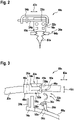
- FIG. 12 shows the windscreen wiper device 10a in an unassembled state in a view from above, which is not part of the invention.
- the windshield wiper device 10a has a wiper arm adapter 14a.
- the wiper arm adapter 14a is provided to partially provide and/or form a coupling region of the wiper arm 66a with the wiper strip 62a and/or the wiper blade 20a.
- the wiper arm adapter 14a is integrally connected to the wiper arm 66a.
- the wiper arm adapter 14a can be formed in one piece with the wiper arm 66a or can be connected to the wiper arm 66a in a non-positive and/or positive manner.
- the wiper arm adapter 14a is provided for a non-positive and/or positive connection with a wiper blade adapter 16a of the windshield wiper device 10a.
- the wiper arm adapter 14a is provided for lateral coupling to the wiper blade adapter 16a.
- the wiper arm adapter 14a is designed as a side-lock wiper arm adapter 14a.
- the wiper arm adapter 14a has at least one coupling element 24a which is intended to be connected to a further coupling element 26a of the wiper blade adapter 16a when the windshield wiper device 10a is in a mounted state.
- the coupling element 24a is designed as a bolt.
- the coupling element 24a has a longitudinal extension which is perpendicular to a longitudinal extension direction of the wiper arm 66a and/or when the windshield wiper device is in a mounted state 10a is aligned perpendicular to a longitudinal extension of the wiper blade 20a.
- the coupling element 24a has a round cross section.
- the cross section of the coupling element 24a is oriented perpendicular to the longitudinal extent of the coupling element 24 .
- the cross-section may be elliptical, oval, polygonal, or the like.
- the coupling element 24a engages at least partially in the wiper blade adapter 16a.
- the windshield wiper device 10a has the wiper blade adapter 16a.
- the wiper blade adapter 16a has a direction of longitudinal extension 40a.
- the direction of longitudinal extension 40a is, in particular in a wiping operating state, aligned perpendicularly to a wiping direction of the windshield wiper 12a in a contact region of the windshield wiper 12a with the vehicle windshield.
- the direction of longitudinal extent 40a of the wiper blade adapter 16a is aligned parallel to the direction of longitudinal extent, in particular a main direction of extent, of the wiper blade 20a in a contact area of the wiper blade adapter 16a with the wiper strip 62a.
- the direction of longitudinal extent 40a of the wiper blade adapter 16a forms the main direction of extent of the wiper blade adapter 16a.
- the main direction of extension can be configured perpendicularly to the direction of longitudinal extension.
- the wiper blade adapter 16a has a direction of transverse extent 42a.
- the direction of transverse extent 42a of the wiper blade adapter 16a is oriented perpendicular to the direction of longitudinal extent 40a of the wiper blade adapter 16a.
- the direction of transverse extent 42a of the wiper blade adapter 16a is aligned parallel to the wiping direction of the windshield wiper 12a in a contact area of the windshield wiper 12a on the vehicle windshield.
- the wiper blade adapter 16a is intended to partially provide and/or form a coupling area of the wiper blade 20 with the wiper arm 66 .
- the wiper blade adapter 16a is captively connected to the wiper strip 62a.
- the wiper blade adapter 16a is non-positively and/or positively connected to the wiper strip 62a.
- the wiper blade adapter 16a at least partially surrounds the wiper strip 62a and/or at least one spring rail 64a.
- the wiper blade adapter 16a can be connected by means of a clamp connection, a latching connection, a rivet connection, in particular a detachable one, and/or by means of another be connected to the wiper strip 62a in a connection that appears sensible to a person skilled in the art.
- the wiper blade adapter 16a has at least one base body 48a.
- the base body 48a forms at least one side wall 46a of the wiper blade adapter 16a, which is aligned perpendicularly to the direction of longitudinal extent 40a of the wiper blade adapter 16a.
- the side wall 46a runs transversely to the direction of longitudinal extension 40a of the wiper blade adapter 16a.
- the wiper blade adapter 16a is provided for a non-positive and/or positive connection with the wiper arm adapter 14a.
- the wiper blade adapter 16a is provided for lateral coupling to the wiper arm adapter 14a.
- the wiper blade adapter 16a is designed as a side-lock wiper blade adapter 16a.
- the wiper blade adapter 16a has a further coupling element 26a, which is intended to be coupled to the coupling element 24a of the wiper arm adapter 14a when the windshield wiper device 10a is in a mounted state.
- the further coupling element 26a is designed as a recess.
- the further coupling element 26a has a longitudinal extension which is aligned perpendicular to the longitudinal extension direction 40a of the wiper blade adapter 16a.
- the longitudinal extent of the further coupling element 26a is aligned parallel to the longitudinal extent of the coupling element 24a of the wiper arm adapter 14a.
- the further coupling element 26a is designed to correspond to the coupling element 24a.
- the further coupling element 26a has a round cross section.
- the cross section of the further coupling element 26a is oriented perpendicular to the longitudinal extent of the further coupling element 24 .
- the cross section of the further coupling element 26a can be elliptical, oval, polygonal or the like.
- the further coupling element 26a is intended to partially accommodate the coupling element 24a of the wiper arm adapter 14a in the assembled state.
- the further coupling element 26a is provided for a form-fitting mounting of the coupling element 24a.
- the further coupling element 26a is provided for a rotatable mounting of the coupling element 24a.
- the coupling elements 24a, 26a form an axis of rotation about which the wiper blade adapter 16a is rotatably mounted relative to the wiper arm adapter 14a.
- the axis of rotation is parallel to the longitudinal extent of the coupling element 24a and/or aligned with the longitudinal extension of the further coupling element 26a.
- the wiper arm adapter 14a is arranged partially offset relative to the wiper blade adapter 16a in the direction of transverse extension 42a of the wiper blade adapter 16a.
- the coupling element 24a and the further coupling element 26a are arranged without offset relative to one another in the direction of transverse extension 42a of the wiper blade adapter 16a.
- the wiper blade adapter 16a has at least one connection unit 44a.
- the connection unit 44a is provided for connecting the wiper blade adapter 16a to a spray unit 22a, in particular to a further spray channel connection element 28a of the spray unit 22a.
- the windshield wiper device 10a has the spray unit 22a.
- the spray unit 22a is provided to spray a washing fluid onto the vehicle window to be wiped in a wiping operating state.
- the spray unit 22a has at least one spray channel unit 34a.
- the spray channel unit 34a is arranged partially within the wiper blade adapter 16a.
- the spray channel unit 34a is partially enclosed by the base body 48a of the wiper blade adapter 16a.
- the spray channel unit 34a has at least one spray channel connection element 30a, which is arranged to guide the washing fluid within the wiper blade adapter 16a.
- the spray channel connection element 30a is provided for supplying the washing fluid to the at least one spray nozzle element.
- the spray unit 22a has at least the spray nozzle element for spraying the washing fluid onto the vehicle window.
- the spray nozzle element is at least partially integrally connected to the spray channel connection element 30a.
- the spray unit 22a has the further spray channel connection element 28a.
- the spray channel connection element 28a is designed as a hose element.
- the spray channel connection element 28a is provided for supplying the washing fluid to the spray channel unit 34a.
- the spray channel connection element 28a is at least non-positively and/or positively connected to the wiper arm 66a tied together. It is also conceivable that the spray channel connection element 28a is materially connected to the wiper arm 66a.
- the spray channel connection element 28a is arranged partially within the wiper arm housing 68a.
- the spray channel connection element 28a is partially arranged in an outer area of the wiper arm housing 68a.
- the spray unit 22a is arranged separately from the wiper arm adapter 14a.
- the further spray channel connection element 28a is intended to be connected to the wiper blade adapter 16a in the assembled state.
- the further spray channel connection element 28a is intended to be connected to the spray channel unit 34a, in particular to the spray channel connection element 30a, in the assembled state.
- the further spray channel connection element 28a is provided for manual coupling to the wiper blade adapter 16a.
- the further spray channel connection element 28a is provided for manual coupling to the spray channel unit 34a, in particular to the spray channel connection element 30a of the wiper blade adapter 16a.
- the spray unit 22a has a locking unit 32a.
- the latching unit 32a is formed in one piece with the connecting unit 44a. Alternatively, the latching unit 32a can be formed and/or arranged separately from the connecting unit 44a.
- the locking unit 32a has a locking element 38a.
- the latching element 38a is formed in a non-positive and/or positive manner with the spray channel connecting element 30a.
- the locking unit 32a has a further locking element 36a.
- the further latching element 36a is non-positively and/or positively connected to the further spray channel connecting element 28a.
- the latching element 38a and the further latching element 36a are provided for a latching connection with one another.
- the latching element 38a and the further latching element 36a are provided for connecting the spray channel connecting element 30a, in particular the spray channel unit 34a, to the further spray channel connecting element 28a.
- the windshield wiper device 10a has a heating unit 18a.
- the heating unit 18a is intended to heat the washing fluid in a wiping operating state.
- the heating unit 18a is intended to heat the wiper blade 20a in a wiping operating state.
- the heating unit 18a has at least one heating element 52a.
- the heating element 52a is designed as an electrical heating element 52a.
- the heating element 52a is partly in the wiper blade adapter 16a, in particular the base body 48a of the wiper blade adapter 16a.
- the heating element 52a is partially enclosed by a base body 48a of the wiper blade adapter 16a.
- the heating unit 18a has a heating connection element 50a.
- the heating connection element 50a is provided for supplying the heating element 52a with electrical energy.
- the heating connection element 50a is formed as a connection cable or a connection wire.
- the heating connection element 50a is arranged on the wiper arm 66a.
- the heating connection element 50a is arranged separately from the wiper arm adapter 14a.
- the heater connector 50a is partially disposed within the wiper arm housing 68a.
- the heating connection element 50a is partially arranged in an outer area of the wiper arm housing 68a.
- the heating connection element 50a preferably has a protective element, for example a protective jacket and/or a protective layer, which is intended to protect the heating connection element 50a of the heating unit 18a from contact with a fluid.
- the heating connection element 50a is arranged separately from the spray channel connection element 28a.
- the heating connection element 50a is provided for manual assembly with a heating element 52a of the heating unit 18a in the wiper blade adapter
- the heating unit 18a has a further locking unit 54a.
- the further latching unit 54a is partially formed in one piece with the connecting unit 44a. Alternatively, the further latching unit 54a can be integrally connected to the connecting unit 44a or formed separately from the connecting unit 44a.
- the further locking unit 54a has an additional locking element 56a.
- the additional latching element 56a is formed with the heating element 52a in a non-positive and/or positive manner.
- the latching unit 54a has a further additional latching element 58a.
- the further additional latching element 58a is non-positively and/or positively connected to the heating connection element 50a.
- the additional latching element 56a and the further additional latching element 58a are provided for a latching connection with one another.
- the additional latching element 56a and the further additional latching element 58a are provided for connecting the heating connection element 50a to the heating element 52a.
- figure 4 12 shows a method of assembling the windshield wiper device 10a.
- the method for assembling the windshield wiper device 10a has at least one method step 70a.
- wiper arm adapter 14b is coupled laterally to wiper arm adapter 14a.
- the further coupling element 24b of the wiper arm adapter 14b is coupled laterally to the coupling element 26b of the wiper blade adapter 16b.
- the method for assembling windshield wiper device 10a has at least one further method step 72a.
- the further spray channel connection element 28a is connected to the spray channel connection element 30a.
- the heating connection element 50a can be connected to the heating element 52a.
- the method for assembling the windshield wiper device 10a is not limited to the method steps mentioned and/or a sequence of the method steps.
- the method can have a number of method steps that differs from the number of method steps mentioned.
- FIG 5 shows an exemplary embodiment of a windshield wiper device 10b according to the invention.
- the windshield wiper device 10b is part of a windshield wiper 12b.
- the windshield wiper device 10b has a wiper arm adapter 14b.
- the wiper arm adapter 14b has a coupling element 24b.
- the windshield wiper device 10b has a wiper blade adapter 16b.
- the wiper blade adapter 16b has a base body 48b.
- the wiper blade adapter 16b has a further coupling element 26b.
- the further coupling element 26b of the wiper blade adapter 16b and the coupling element 24b of the wiper arm adapter 14b are provided for a lateral coupling, in particular side-lock coupling, of the wiper arm adapter 14b to the wiper blade adapter 16b.
- the windshield wiper device 10b has a spray unit 22b.
- the spray unit 22b has a spray channel unit 34b.
- the spray channel unit 34b is partially arranged in the wiper blade adapter 16b.
- the spray channel unit 34b has a spray channel connection element 30b.
- the spray channel connection element 30b is arranged in the wiper blade adapter 16b.
- the spray channel connection element 30b is connected to the further coupling element 26b.
- the spray unit 22b has a further spray channel connection element 28b.
- the further spray channel connection element 28b is arranged partially inside a wiper arm 66b of the windshield wiper 12b.
- the further spray channel connection element 28b is partially arranged in the wiper arm adapter 14b.
- the further spray channel connection element 28b is connected to the coupling element 24b.
- the further spray channel connection element 28b is, in particular in contrast to the first exemplary embodiment, at least partially arranged in the coupling element 24b.
- the spray channel connection element 30b of the wiper blade adapter 16b and the further spray channel connection element 28b of the wiper arm adapter 14b are provided for automatic coupling when the wiper arm adapter 14b is coupled to the wiper blade adapter 16b.
- the spray channel connection element 30b of the wiper blade adapter 16b and the further spray channel connection element 28b of the wiper arm adapter 14b are provided for automatic coupling when the further coupling element 26b is coupled to the coupling element 24b.
- the spray unit 22b it is conceivable for the spray unit 22b to have a latching unit 32b, which has a latching element 36b connected to the spray channel connection element 30b in a non-positive and/or positive or material connection and/or another latching element that is connected to the further spray channel connection element 28b in a non-positive and/or positive or material connection 38b has, wherein the locking element 36b and the further latching element 38b are intended in particular to be connected to one another in a non-positive and/or positive manner in an assembled state.
- windshield wiper device 10b has a heating unit 18b, heating unit 18b having a heating element 52b arranged in wiper blade adapter 16b and a heating connection element 50b partly arranged in coupling element 24b of wiper arm adapter 14b.
- the heating unit 18b has a further latching unit 54b, which has an additional latching element 56b connected to the heating element 52b in a non-positive and/or positive or material connection and/or a further additional latching element 58b connected to the heating connection element 50b in a non-positive and/or positive or material connection , wherein the additional latching element 36b and the further additional latching element 38b are provided in particular to be non-positively and/or positively connected to one another for assembly.
Landscapes
- Engineering & Computer Science (AREA)
- Mechanical Engineering (AREA)
- Water Supply & Treatment (AREA)
- Body Structure For Vehicles (AREA)
- Cleaning By Liquid Or Steam (AREA)
- Nozzles (AREA)
Description
- Es ist bereits eine Scheibenwischervorrichtung für einen Scheibenwischer, mit zumindest einem Wischarmadapter, mit zumindest einem Wischblattadapter und mit einer Heizeinheit zum Heizen eines Wischblatts und einer Sprüheinheit zu einem Aufsprühen eines Waschfluids auf eine Fahrzeugscheibe, wobei die Sprüheinheit und die Heizeinheit zumindest teilweise in dem Wischblattadapter angeordnet sind, vorgeschlagen worden
DE 10 2008 049 270 A1 offenbart den Oberbegriff des Anspruchs 1. - Die Erfindung geht aus von einer Scheibenwischervorrichtung für einen Scheibenwischer, mit zumindest einem Wischarmadapter, mit zumindest einem Wischblattadapter und mit einer Heizeinheit zum Heizen eines Wischblatts und einer Sprüheinheit zu einem Aufsprühen eines Waschfluids auf eine Fahrzeugscheibe, wobei die Sprüheinheit und die Heizeinheit zumindest teilweise in dem Wischblattadapter angeordnet sind.
- Nach der Erfindung wird vorgeschlagen, dass der Wischarmadapter und der Wischblattadapter Kopplungselemente aufweisen, welche zu einer seitlichen Kopplung des Wischarmadapters mit dem Wischblattadapter vorgesehen sind. Durch die erfindungsgemäße Ausgestaltung der Scheibenwischervorrichtung kann eine besonders einfache Kopplung des Wischarmadapters mit dem Wischblattadapter erreicht werden. Weiterhin kann vorteilhaft eine einfache Montage der Sprüheinheit und/oder der Heizeinheit erreicht werden. Weiterhin können die Sprüheinheit und die Heizeinheit bauraumsparend angeordnet werden, wodurch zudem vorteilhaft ein Luftwiderstand bei einer Wischbewegung gering gehalten und vorteilhafte Wischeigenschaften erreicht werden können.
- Unter einer "Scheibenwischervorrichtung" soll insbesondere zumindest ein Teil, insbesondere eine Unterbaugruppe, eines Scheibenwischers verstanden werden, wobei insbesondere zusätzlich auch Zubehöreinheiten für den Scheibenwischer umfasst sein können. Insbesondere kann die Scheibenwischervorrichtung auch den gesamten Scheibenwischer umfassen. Unter einem "Wischblattadapter" soll insbesondere ein Adapter verstanden werden, der vorzugsweise einen Kontaktbereich zu einem Wischblattbauteil, insbesondere eine Wischleiste und/oder zumindest eine Federschiene, aufweist und bevorzugt mit dem Wischblattbauteil unverlierbar verbunden und insbesondere dazu vorgesehen ist, einen Kopplungsbereich des Wischblattbauteils für eine Kopplung und/oder Kontaktierung mit einem Wischarmadapter bereitzustellen. Unter einem "Wischarmadapter" soll in diesem Zusammenhang insbesondere ein Adapter verstanden werden, der einen Kontaktbereich zu einem Wischarm aufweist und bevorzugt mit dem Wischarm unverlierbar verbunden und insbesondere dazu vorgesehen ist, einen Kopplungsbereich des Wischarms für eine Kopplung und/oder Kontaktierung mit dem Wischblattadapter bereitzustellen. Vorzugsweise ist der Wischarmadapter zumindest teilweise kraft- und/oder formschlüssig mit dem Wischarm verbunden und/oder zumindest teilweise einstückig mit dem Wischarm ausgebildet. Unter "zumindest teilweise einstückig" soll in diesem Zusammenhang insbesondere verstanden werden, dass zumindest ein Bauteil zumindest eines Objekts und/oder zumindest ein erstes Objekt einstückig mit zumindest einem Bauteil zumindest eines weiteren Objekts und/oder einstückig mit zumindest einem weiteren Objekt ausgebildet ist. Unter "einstückig" soll insbesondere zumindest stoffschlüssig verbunden verstanden werden, beispielsweise durch einen Schweißprozess, einen Klebeprozess, einen Anspritzprozess und/oder einen anderen, dem Fachmann als sinnvoll erscheinenden Prozess, und/oder vorteilhaft in einem Stück geformt verstanden werden.
- Unter einem "Kopplungselement" soll insbesondere ein Bauteil verstanden werden, welches dazu vorgesehen ist, in einem montierten Zustand insbesondere mit einem zu dem Kopplungselement korrespondierend ausgebildeten weiteren Kopplungselement kraft und/formschlüssig und vorzugsweise lösbar gekoppelt zu sein. Insbesondere ist das Kopplungselement dazu vorgesehen, ein mit dem Kopplungselement kraft- und/oder formschlüssig oder stoffschlüssig verbundenes Objekt, insbesondere den Wischarmadapter, mit einem mit dem weiteren Kopplungselement kraft- und/oder formschlüssig verbundenen oder zumindest teileweise einstückig ausgebildeten Objekt, insbesondere dem Wischblattadapter, kraft- und/oder formschlüssig und vorzugsweise lösbar zu verbinden. Unter einer "seitlichen Kopplung des Wischarmadapters mit dem Wischblattadapter" soll insbesondere verstanden werden, dass der Wischblattadapter und der Wischarmadapter mittels einer Bewegung entlang einer Kopplungsachse koppelbar sind, welche insbesondere zumindest im Wesentlichen senkrecht einer Längserstreckungsrichtung des Wischblattadapters ausgerichtet ist. Insbesondere ist die Kopplungsachse im Wesentlichen parallel zu einer Quererstreckungsrichtung des Wischblattadapters ausgerichtet. Insbesondere ist die Kopplungsachse zumindest teilweise parallel zu der Fahrzeugscheibe, insbesondere in einem Kontaktbereich des Scheibenwischers mit der Fahrzeugscheibe, ausgerichtet. Insbesondere greift zumindest ein Kopplungselement des Wischarmadapters zumindest teilweise in eine Seitenwandung des Wischblattadapters ein. Vorzugsweise greift das Kopplungselement des Wischarmadapters in das Kopplungselement des Wischblattadapters ein. Insbesondere ist in einem montierten Zustand zumindest die Oberfläche einer Seitenwandung des Wischblattadapters mit zumindest der Seitenwandung, des Wischarmadapters vorzugsweise kontaktiert. Insbesondere ist die Kopplungsachse insbesondere im Wesentlichen parallel zu einer Quererstreckungsrichtung des Wischblattadapters ausgerichtet. Unter "zumindest im Wesentlichen parallel" soll hier insbesondere eine Ausrichtung einer Richtung relativ zu einer Bezugsrichtung, insbesondere in einer Ebene, verstanden werden, wobei die Richtung gegenüber der Bezugsrichtung eine Abweichung insbesondere kleiner als 8°, vorteilhaft kleiner als 5° und besonders vorteilhaft kleiner als 2° aufweist. Unter einer "Quererstreckungsrichtung" eines Objekts, insbesondere des Wischblattadapters, soll insbesondere eine Richtung verstanden werden, welche senkrecht zu einer Längserstreckungsrichtung des Wischblattadapters und insbesondere parallel zu einer Fahrzeugscheibe, insbesondere im Kontaktbereich des Scheibenwischers mit der Fahrzeugscheibe, ausgerichtet ist. Unter einer "Längserstreckungsrichtung" eines Objekts soll insbesondere eine Richtung verstanden werden, welche parallel zu einer längsten Seite eines kleinsten gedachten geometrischen Quaders ausgerichtet ist, welcher das Objekt gerade noch vollständig umschließt.
- Unter einer "Sprüheinheit" soll in diesem Zusammenhang insbesondere eine Einheit verstanden werden, die insbesondere zu einem Aufsprühen eines Waschfluids auf die Fahrzeugscheibe vorgesehen ist. Vorzugsweise weist die Sprüheinheit zumindest eine Sprühkanaleinheit auf, welche vorzugsweise im Wischblattadapter, der Wischleiste und/oder der Spoilereinheit angeordnet ist. Insbesondere weist die Sprüheinheit zu einem Aufsprühen zumindest ein Sprühdüsenelement auf, welches vorzugsweise zumindest teilweise einstückig mit der Sprühkanaleinheit ausgebildet ist. Zudem weist die Sprühkanaleinheit bevorzugt ein Sprühkanalverbindungselement auf, welches insbesondere dazu vorgesehen ist, das zumindest eine Sprühdüsenelement mit dem Waschfluid zu versorgen. Zusätzlich weist die Sprüheinheit vorzugsweise ein weiteres Sprühkanalverbindungselement auf, welches in dem Wischarm und/oder dem Wischarmadapter angeordnet ist und in einem montierten Zustand zu einer Versorgung der Sprühkanaleinheit mit dem Waschfluid vorgesehen ist. Unter einer "Heizeinheit" soll insbesondere eine Einheit verstanden werden, die dazu vorgesehen ist, das Waschfluid und/oder das Wischblatt zu heizen. Die Heizeinheit weist zumindest ein Heizelement auf, welches vorzugsweise in dem Wischblattadapter, der Wischleiste und/oder der Spoilereinheit angeordnet ist. Die Heizeinheit ist vorzugweise zumindest teilweise im Wesentlichen parallel zu der Sprühkanaleinheit der Sprüheinheit angeordnet.
- Nach der Erfindung wird vorgeschlagen, dass die Sprüheinheit zumindest ein mit zumindest einem Kopplungselement zumindest teilweise verbundenes Sprühkanalverbindungselement aufweist, welches zu einer zumindest teilweise automatischen Kopplung mit einem weiteren Sprühkanalverbindungselement am Wischarm adapter vorgesehen ist. Unter einer "zumindest teilweise automatischen Kopplung" soll insbesondere eine Kopplung zweier Objekte verstanden werden, welche ohne eine äußere Einwirkung, insbesondere Krafteinwirkung eines Bedieners, insbesondere ohne ein Stecken, Schrauben, Pressen, Drücken und/oder eine andere, dem Fachmann als sinnvolle erscheinende Einwirkung, bewirkbar ist. Insbesondere kann mittels der seitlichen Kopplung des Wischarmadapters mit dem Wischblattadapter zusätzlich die Kopplung der Sprüheinheit, insbesondere des Sprühkanalverbindungselements, welches vorzugsweise zumindest teilweise kraft- und/oder formschlüssig oder stoffschlüssig mit dem Kopplungselement des Wischarmadapters verbunden ist, vorzugsweise mittels einer Rastverbindung mit dem weiteren Sprühkanalverbindungselement, welches bevorzugt zumindest teilweise kraft- und/oder formschlüssig oder stoffschlüssig mit dem Kopplungselement des Wischarmadapters verbunden ist, verbunden werden. Insbesondere ist die Rastverbindung des Sprühkanalverbindungselements mit dem weiteren Sprühkanalverbindungselement dazu vorgesehen, bei der Kopplung des Wischarmadapters mit dem Wischblattadapter insbesondere zumindest teilweise automatisch gekoppelt zu werden. Durch die erfindungsgemäße Ausgestaltung kann die Sprüheinheit besonders baumraumsparend angeordnet werden. Zudem kann vorteilhaft eine Montage des Sprühkanalverbindungselements mit dem weiteren Sprühkanalverbindungselement der Sprüheinheit besonders einfach ausgestaltet werden.
- Ferner wird vorgeschlagen, dass der Wischarmadapter zumindest teilweise getrennt von der Sprüheinheit und/oder der Heizeinheit angeordnet ist. Insbesondere ist der Wischarmadapter kraft- und/oder formschlüssig und bevorzugt einstückig mit dem Wischarm verbunden und bevorzugt in einem Endbereich des Wischarms angeordnet. Unter "getrennt" angeordnet soll insbesondere verstanden werden, dass ein Objekt beabstandet zu zumindest einem weiteren Objekt angeordnet ist. Durch die erfindungsgemäße Ausgestaltung können/kann vorteilhaft die Sprüheinheit und/oder die Heizeinheit, insbesondere das Sprühkanalverbindungselement der Sprüheinheit, und/oder die Heizeinheit, insbesondere das Heizverbindungselement der Heizeinheit für einen Bediener zu einer Montage besonders leicht erreichbar angeordnet werden, wodurch insbesondere das Sprühkanalverbindungselement der Sprüheinheit, und/oder die Heizeinheit, insbesondere das Heizverbindungselement der Heizeinheit, besonders einfach und manuell mit dem Wischblattadapter verbunden werden können.
- Außerdem wird vorgeschlagen, dass die Sprüheinheit zumindest ein Sprühkanalverbindungselement aufweist, welches zu einer zumindest teilweise manuellen Kopplung mit dem Wischblattadapter vorgesehen ist. Unter einer "zumindest teilweise manuellen Kopplung" soll insbesondere eine Kopplung eines Objekts mit einem weiteren Objekt verstanden, wobei eine äußere Einwirkung, insbesondere eine Krafteinwirkung eines Bedieners, auf das Objekt zumindest teilweise eine Kopplung des Objekts mit dem weiteren Objekt bewirkt. Insbesondere ist das Sprühkanalverbindungselement zumindest teilweise als ein Schlauchelement ausgebildet, welches zur Führung des Waschfluids vorgesehen ist. Vorzugsweise weist zusätzlich die Heizeinheit ein Heizverbindungselement auf, welches zu einer zumindest teilweise manuellen Kopplung mit dem Wischblattadapter vorgesehen ist. Durch die erfindungsgemäße Ausgestaltung können/kann vorteilhaft die Sprüheinheit und/oder die Heizeinheit besonders einfach mit dem Wischblattadapter verbunden werden. Zudem können/kann ein Reparatur- und/oder Wartungsaufwand der Sprüheinheit, der Heizeinheit und der Scheibenwischervorrichtung gering gehalten werden.
- Weiterhin wird vorgeschlagen, dass die Sprüheinheit zumindest eine Rasteinheit aufweist, welche zu einer kraft- und/oder formschlüssigen Verbindung des Sprühkanalverbindungselements mit einer Sprühkanaleinheit der Sprüheinheit im Wischblattadapter vorgesehen ist. Insbesondere weist die Rasteinheit zumindest ein Rastelement auf, welches kraft- und/oder formschlüssig oder stoffschlüssig, insbesondere einstückig, mit dem Sprühkanalverbindungselement ausgebildet ist. Vorzugsweise weist die Rasteinheit zumindest ein weiteres Rastelement auf, welches kraft- und/oder formschlüssig oder stoffschlüssig mit einem weiteren Sprühkanalverbindungselement des Wischblattadapters ausgebildet, und zu einer Rastverbindung mit dem Rastelement des Sprühkanalverbindungselements vorgesehen ist. Vorzugsweise ist das weitere Rastelement kraft-, stoff- und/oder formschlüssig mit dem Wischblattadapter, insbesondere einem Grundkörper des Wischblattadapters, verbunden. Durch die erfindungsgemäße Ausgestaltung kann vorteilhaft eine besonderes einfache Montage des Wischarmadapters, der Sprüheinheit erreicht werden. Zudem können/kann ein Reparatur- und/oder Wartungsaufwand der Sprüheinheit gering gehalten werden.
- Zudem wird vorgeschlagen, dass der Wischblattadapter eine an zumindest einer zu einer Längserstreckungsrichtung des Wischblattadapters quer verlaufenden Seitenwand angeordnete Verbindungseinheit aufweist, die zu einer Verbindung mit dem Sprühkanalverbindungselement vorgesehen ist. Insbesondere ist die Längserstreckungsrichtung des Wischblattadapters im Wesentlichen parallel zu einer Längserstreckungsrichtung des Wischblatts ausgerichtet. Insbesondere ist eine Oberfläche der Seitenwandung des Wischblattadapters quer zur Längserstreckungsrichtung ausgerichtet. Unter "quer" soll hier insbesondere "zumindest im Wesentlichen senkrecht" verstanden werden. Unter "zumindest im Wesentlichen senkrecht" soll insbesondere eine Ausrichtung einer Richtung relativ zu einer Bezugsrichtung, insbesondere in einer Ebene, verstanden werden, wobei die Richtung und die Bezugsrichtung einen Winkel einschließen, welcher um weniger als 8°, vorteilhaft weniger als 5° und besonders vorteilhaft weniger als 2° von einem rechten Winkel abweicht. Insbesondere ist die Verbindungseinheit dazu vorgesehen, das Sprühkanalverbindungselement und/oder das Heizverbindungselement mit dem Wischblattadapter insbesondere mit einem weiteren Sprühkanalverbindungselement und/oder dem Heizelement der Heizeinheit zu verbinden. Insbesondere ist die Verbindungseinheit mit einer Rasteinheit, insbesondere der bereits erwähnten Rasteinheit, kraft- und/oder formschlüssig, stoffschlüssig verbunden und bildet eine kraft-und/oder formschlüssige Verbindung des Sprühkanalelements und/oder des Heizverbindungselements mit dem Wischblattadapter aus. Durch die erfindungsgemäße Ausgestaltung kann insbesondere eine besonders einfache Kopplung des Sprühkanalverbindungselements und/oder des Heizverbindungselements bereitgestellt werden.
- Außerdem wird vorgeschlagen, dass die Heizeinheit zumindest ein Heizverbindungselement aufweist, welches zu einer zumindest teilweise manuellen Montage mit einem Heizelement der Heizeinheit in dem Wischblattadapter vorgesehen ist. Insbesondere ist das Heizverbindungselement zumindest teilweise als ein Verbindungskabel ausgebildet, welches zur Versorgung des Heizelements der Heizeinheit mit einer elektrischen Energie vorgesehen ist. Insbesondere ist das Heizverbindungselement vorzugsweise zumindest teilweise getrennt von dem Sprühkanalverbindungselement angeordnet. Durch die erfindungsgemäße Ausgestaltung können/kann vorteilhaft die Sprüheinheit und/oder die Heizeinheit besonders einfach mit dem Wischblattadapter verbunden werden. Zudem können/kann ein Reparatur- und/oder Wartungsaufwand der Heizeinheit und/oder der Scheibenwischervorrichtung gering gehalten werden.
- Ferner wird vorgeschlagen, dass die Heizeinheit zumindest eine Rasteinheit aufweist, welche zu einer kraft- und/oder formschlüssigen Verbindung des Heizverbindungselements mit einem Heizelement der Heizeinheit im Wischblattadapter vorgesehen ist. Insbesondere weist die Rasteinheit zumindest ein Rastelement auf, welches kraft- und/oder formschlüssig mit dem Heizverbindungselement verbunden oder zumindest teilweise einstückig mit dem Heizverbindungselement ausgebildet ist. Vorzugsweise weist die Rasteinheit zumindest ein weiteres Rastelement auf, welches kraft- und/oder formschlüssig oder stoffschlüssig mit dem Heizelement im Wischblattadapter verbunden und zu einer Rastverbindung mit dem Rastelement des Heizverbindungselements vorgesehen ist. Vorzugsweise ist das weitere Rastelement kraft-, stoff, und/oder form-schlüssig mit dem Wischblattadapter verbunden. Es ist denkbar, dass die Rasteinheit der Heizeinheit zumindest teilweise einstückig mit der Rasteinheit der Sprüheinheit verbunden ist. Es ist denkbar, dass insbesondere das Rastelement an dem Sprühkanalverbindungselement mit dem Rastelement am Heizverbindungselement einstückig verbunden ist. Durch die erfindungsgemäße Ausgestaltung kann vorteilhaft eine besonderes einfache Montage des Wischarmadapters der Heizeinheit erreicht werden. Zudem können/kann ein Reparatur- und/oder Wartungsaufwand der Heizeinheit gering gehalten werden.
- Zudem wird ein Scheibenwischer mit einer Scheibenwischervorrichtung vorgeschlagen. Durch die erfindungsgemäße Ausgestaltung des Scheibenwischers kann eine besonders einfache Kopplung des Wischarmadapters mit dem Wischblattadapter erreicht werden. Zudem kann eine besonders einfache Montage des Wischarmadapters mit dem Wischblattadapter erreicht werden. Weiterhin kann vorteilhaft eine einfache Montage der Sprüheinheit und der Heizeinheit erreicht werden. Weiterhin können die Sprüheinheit und die Heizeinheit bauraumsparend angeordnet werden, wodurch zudem vorteilhaft ein Luftwiderstand bei einer Wischbewegung gering gehalten und vorteilhafte Wischeigenschaften erreicht werden können.
- Zudem wird ein Verfahren vorgeschlagen, wobei in zumindest einem Verfahrensschritt die Sprüheinheit und die Heizeinheit nach einer seitlichen Kopplung des Wischarmadapters mit dem Wischblattadapter, Spühkanalverbindungselemente der Sprüheinheit und Heizverbindungselemente der Heizeinheit verbunden werden. Durch die erfindungsgemäße Ausgestaltung der Scheibenwischervorrichtung kann eine besonders einfache Kopplung des Wischarmadapters mit dem Wischblattadapter erreicht werden. Zudem kann eine besonders einfache Montage des Wischarmadapters mit dem Wischblattadapters erreicht werden. Weiterhin kann vorteilhaft eine einfache Montage der Sprüheinheit und der Heizeinheit erreicht werden. Weiterhin können die Sprüheinheit und die Heizeinheit bauraumsparend angeordnet werden, wodurch zudem vorteilhaft ein Luftwiderstand bei einer Wischbewegung gering gehalten und vorteilhafte Wischeigenschaften erreicht werden können.
- Zeichnungen Weitere Vorteile ergeben sich aus der folgenden Zeichnungsbeschreibung. In den Zeichnungen sind zwei Ausführungsbeispiele dargestellt.
- Es zeigen:
- Fig. 1
- einen Scheibenwischer mit einer Scheibenwischervorrichtung in einer vereinfachten Darstellung von oben,
- Fig. 2
- die Scheibenwischervorrichtung in einer vereinfachten Darstellung von oben,
- Fig. 3
- eine nicht zur Erfindung gehörende Scheibenwischervorrichtung in einer vereinfachten Darstellung in einer seitlichen Schnittansicht, wobei die Schnittebene senkrecht zu einer Längserstreckungsrichtung des Wischblattadapters angeordnet ist,
- Fig. 4
- ein Verfahren zur Montage der Scheibenwischervorrichtung in einer stark vereinfachten Verlaufsdarstellung und
- Fig. 5
- ein erfindungsgemäße weiteres Ausführungsbeispiel der Scheibenwischervorrichtung in einer vereinfachten Darstellung von oben.
-
Figur 1 zeigt einen Scheibenwischer 12a. Der Scheibenwischer 12a ist dazu vorgesehen, eine Fahrzeugscheibe eines Fahrzeugs zu wischen. Der Scheibenwischer 12a ist als ein Windabweiserscheibenwischer ausgebildet. Wie zusätzlichFigur 2 in einer seitlichen Darstellung des Scheibenwischers 12a zeigt, weist der Scheibenwischer 12a zumindest ein Wischblatt 20a auf. Das Wischblatt 20a weist zumindest eine Wischleiste 62a auf. Die Wischleiste 62a, insbesondere eine Wischlippe der Wischleiste 62a, ist dazu vorgesehen, zu einem Wischen der Fahrzeugscheibe mit der Fahrzeugscheibe kontaktiert zu sein. Zudem weist der Scheibenwischer 12a zumindest eine Federschiene 64a auf, welche dazu vorgesehen ist, das Wischblatt 20a, insbesondere die Wischleiste 62a, mit einer Spannkraft zu beaufschlagen. Zudem weist die Wischleiste 62a zumindest eine Spoilereinheit (hier nicht gezeigt) auf. Die Spoilereinheit ist auf einer von der Fahrzeugscheibe abgewandten Seite des Wischblatts 20a angeordnet. Alternativ kann der Scheibenwischer 12a auch in Flachbauweise als Flachbalkenscheibenwischer ausgebildet sein, wobei auf eine Spoilereinheit verzichtet werden könnte. - Der Scheibenwischer 12a weist einen Wischarm 66a auf (vgl.
Figur 1 ). Der Wischarm 66a ist drehbar an einem Fahrzeugbauteil gelagert. Der Wischarm 66a ist dazu vorgesehen, den Scheibenwischer 12a, insbesondere das Wischblatt 20a, mit einer Wischbewegung zu beaufschlagen. Der Wischarm 66a kann einen Wischarmkörper (hier nicht gezeigt) und ein Wischarmgehäuse 68a aufweisen. Das Wischarmgehäuse 68a begrenzt einen Innenraum des Wischarms 66a. - Der Scheibenwischer 12a weist eine Scheibenwischervorrichtung 10a auf. Die Scheibenwischervorrichtung 10a ist dazu vorgesehen, den Wischarm 66a mit dem Wischblatt 20a und/oder der Wischleiste 62a zu verbinden. Die Scheibenwischervorrichtung 10a ist zu einer lösbaren Verbindung des Wischarms 66a mit dem Wischblatt 20a und/oder der Wischleiste 62a vorgesehen. Die Scheibenwischervorrichtung 10a ist auf einer der Fahrzeugscheibe abgewandten Seite der Wischleiste 62a angeordnet. Die Scheibenwischervorrichtung 10a ist zumindest teilweise unlösbar mit der Wischleiste 62a verbunden. Die Scheibenwischervorrichtung 10a ist zumindest teilwiese kraft- und/oder formschlüssig mit dem Wischarm 66a verbunden. Vorzugsweise ist die Scheibenwischervorrichtung 10a zumindest teilweise stoffschlüssig mit dem Wischarm 66a verbunden. Es ist alternativ denkbar, dass die Scheibenwischervorrichtung 10a teilweise einstückig mit dem Wischarm 66a verbunden ist. Zudem ist alternativ denkbar, dass die Scheibenwischervorrichtung 10a lösbar mit der Wischleist 62a verbunden ist.
-
Figur 3 zeigt die Scheibenwischervorrichtung 10a in einem nicht montierten Zustand in einer Ansicht von oben, die nicht Teil der Erfindung ist. Die Scheibenwischervorrichtung 10a weist einen Wischarmadapter 14a auf. Der Wischarmadapter 14a ist dazu vorgesehen, einen Kopplungsbereich des Wischarms 66a mit der Wischleiste 62a und/oder dem Wischblatt 20a teilweise bereitzustellen und/oder auszubilden. Der Wischarmadapter 14a ist stoffschlüssig mit dem Wischarm 66a verbunden. Alternativ kann der Wischarmadapter 14a einstückig mit dem Wischarm 66a ausgebildet oder kraft- und/oder formschlüssig mit dem Wischarm 66a verbunden sein. - Der Wischarmadapter 14a ist zu einer kraft- und/oder formschlüssigen Verbindung mit einem Wischblattadapter 16a der Scheibenwischervorrichtung 10a vorgesehen. Der Wischarmadapter 14a ist zu einer seitlichen Kopplung mit dem Wischblattadapter 16a vorgesehen. Der Wischarmadapter 14a ist als ein Side-Lock Wischarmadapter 14a ausgebildet. Der Wischarmadapter 14a weist zumindest ein Kopplungselement 24a auf, welches dazu vorgesehen ist, in einem montierten Zustand der Scheibenwischervorrichtung 10a mit einem weiteren Kopplungselement 26a des Wischblattadapters 16a verbunden zu werden. Das Kopplungselement 24a ist als ein Bolzen ausgebildet. Das Kopplungselement 24a weist eine Längserstreckung auf, welche senkrecht zu einer Längserstreckungsrichtung des Wischarms 66a und/oder in einem montierten Zustand der Scheibenwischervorrichtung 10a senkrecht zu einer Längserstreckung des Wischblatts 20a ausgerichtet ist. Das Kopplungselement 24a weist einen runden Querschnitt auf. Der Querschnitt des Kopplungselement 24a ist senkrecht zu der Längserstreckung des Kopplungselements 24 ausgerichtet. Alternativ kann der Querschnitt elliptisch, oval, polygonförmig oder dergleichen geformt sein. Das Kopplungselement 24a greift in dem montierten Zustand zumindest teilweise in den Wischblattadapter 16a ein.
- Die Scheibenwischervorrichtung 10a weist den Wischblattadapter 16a auf. Der Wischblattadapter 16a weist eine Längserstreckungsrichtung 40a auf. Die Längserstreckungsrichtung 40a ist, insbesondere in einem Wischbetriebszustand, senkrecht zu einer Wischrichtung des Scheibenwischers 12a in einem Kontaktbereich des Scheibenwischers 12a mit der Fahrzeugscheibe ausgerichtet. Die Längserstreckungsrichtung 40a des Wischblattadapters 16a ist parallel zu der Längserstreckungsrichtung, insbesondere einer Haupterstreckungsrichtung, des Wischblatts 20a in einem Kontaktbereich des Wischblattadapters 16a mit der Wischleiste 62a ausgerichtet. Die Längserstreckungsrichtung 40a des Wischblattadapters 16a bildet die Haupterstreckungsrichtung der Wischblattadapters 16a aus. Alternativ kann die Haupterstreckungsrichtung senkrecht zu der Längserstreckungsrichtung ausgebildet sein. Der Wischblattadapter 16a weist eine Quererstreckungsrichtung 42a auf. Die Quererstreckungsrichtung 42a des Wischblattadapters 16a ist senkrecht zu der Längserstreckungsrichtung 40a des Wischblattadapters 16a ausgerichtet. Die Quererstreckungsrichtung 42a des Wischblattadapters 16a ist parallel zu der Wischrichtung des Scheibenwischers 12a in einem Kontaktbereich des Scheibenwischers 12a auf der Fahrzeugscheibe ausgerichtet.
- Der Wischblattadapter 16a ist dazu vorgesehen, einen Kopplungsbereich des Wischblatts 20 mit dem Wischarm 66 teilweise bereitzustellen und/oder auszubilden. Der Wischblattadapter 16a ist unverlierbar mit der Wischleiste 62a verbunden. Der Wischblattadapter 16a ist kraft- und/oder formschlüssig mit der Wischleiste 62a verbunden. Der Wischblattadapter 16a umgreift die Wischleiste 62a und/oder zumindest eine Federschiene 64a zumindest teilweise. Alternativ kann der Wischblattadapter 16a mittels einer Klemmverbindung, einer Rastverbindung, einer, insbesondere lösbaren Nietverbindung und/oder mittels einer anderen, dem Fachmann als sinnvoll erscheinenden Verbindung mit der Wischleiste 62a verbunden sein.
- Der Wischblattadapter 16a weist zumindest einen Grundkörper 48a. Der Grundkörper 48a bildet zumindest eine Seitenwandung 46a des Wischblattadapters 16a aus, welche senkrecht zu der Längserstreckungsrichtung 40a des Wischblattadapters 16a ausgerichtet ist. Die Seitenwandung 46a verläuft quer zur Längserstreckungsrichtung 40a des Wischblattadapters 16a.
- Der Wischblattadapter 16a ist zu einer kraft- und/oder formschlüssigen Verbindung mit dem Wischarmadapter 14a vorgesehen. Der Wischblattadapter 16a ist zu einer seitlichen Kopplung mit dem Wischarmadapter 14a vorgesehen. Der Wischblattadapter 16a ist als ein Side-Lock Wischblattadapter 16a ausgebildet Der Wischblattadapter 16a weist ein weiteres Kopplungselement 26a auf, welches dazu vorgesehen ist, in einem montierten Zustand der Scheibenwischervorrichtung 10a mit dem Kopplungselement 24a des Wischarmadapters 14a gekoppelt zu sein. Das weitere Kopplungselement 26a ist als eine Ausnehmung ausgebildet. Das weitere Kopplungselement 26a weist eine Längserstreckung auf, welche senkrecht zu der Längserstreckungsrichtung 40a des Wischblattadapters 16a ausgerichtet ist. Die Längserstreckung des weiteren Kopplungselements 26a ist parallel zur Längserstreckung des Kopplungselements 24a des Wischarmadapters 14a ausgerichtet. Das weitere Kopplungselement 26a ist korrespondierend zu dem Kopplungselement 24a ausgebildet. Das weitere Kopplungselement 26a weist einen runden Querschnitt auf. Der Querschnitt des weiteren Kopplungselement 26a ist senkrecht zu der Längserstreckung des weiteren Kopplungselements 24 ausgerichtet. Alternativ kann der Querschnitt des weiteren Kopplungselements 26a elliptisch, oval, polygonförmig oder dergleichen geformt sein. Das weitere Kopplungselement 26a ist dazu vorgesehen, in dem montierten Zustand das Kopplungselement 24a des Wischarmadapters 14a teilweise aufzunehmen. Das weitere Kopplungselement 26a ist zu einer formschlüssigen Lagerung des Kopplungselements 24a vorgesehen. Das weitere Kopplungselement 26a ist zu einer drehbaren Lagerung des Kopplungselements 24a vorgesehen. Die Kopplungselemente 24a, 26a bilden eine Drehachse aus, um welche der Wischblattadapter 16a relativ zu dem Wischarmadapter 14a drehbar gelagert ist. Die Drehachse ist parallel zur Längserstreckung des Kopplungselements 24a und/oder zur Längserstreckung des weiteren Kopplungselements 26a ausgerichtet.
- In einem montierten Zustand ist der Wischarmadapter 14a in Quererstreckungsrichtung 42a des Wischblattadapters 16a teilweise versetzt zu dem Wischblattadapter 16a angeordnet. In dem montierten Zustand sind das Kopplungselement 24a und das weitere Kopplungselement 26a in Quererstreckungsrichtung 42a des Wischblattadapters 16a versatzlos zueinander angeordnet. Der Wischblattadapter 16a weist zumindest eine Verbindungseinheit 44a auf. Die Verbindungseinheit 44a ist zu einer Verbindung des Wischblattadapters 16a mit einer Sprüheinheit 22a, insbesondere einem weiteren Sprühkanalverbindungselement 28a der Sprüheinheit 22a, vorgesehen.
- Die Scheibenwischervorrichtung 10a weist die Sprüheinheit 22a auf. Die Sprüheinheit 22a ist dazu vorgesehen, in einem Wischbetriebszustand ein Waschfluid auf die zu wischende Fahrzeugscheibe zu sprühen. Die Sprüheinheit 22a weist dazu zumindest eine Sprühkanaleinheit 34a auf. Die Sprühkanaleinheit 34a ist teilweise innerhalb des Wischblattadapters 16a angeordnet. Die Sprühkanaleinheit 34a ist teilweise von dem Grundkörper 48a des Wischblattadapters 16a umschlossen.
- Die Sprühkanaleinheit 34a weist zumindest ein Sprühkanalverbindungselement 30a auf, welches zu einem Führen des Waschfluids innerhalb des Wischblattadapters 16a angeordnet ist. Das Sprühkanalverbindungselement 30a ist dazu vorgesehen, dem zumindest einen Sprühdüsenelement das Waschfluid zuzuführen.
- Die Sprüheinheit 22a weist zumindest das Sprühdüsenelement zu einem Sprühen des Waschfluids auf die Fahrzeugscheibe auf. Das Sprühdüsenelement ist zumindest teilweise einstückig mit dem Sprühkanalverbindungselement 30a verbunden. Die Sprüheinheit 22a weist das weitere Sprühkanalverbindungselement 28a auf. Das Sprühkanalverbindungselement 28a ist als ein Schlauchelement ausgebildet. Das Sprühkanalverbindungselement 28a ist dazu vorgesehen, der Sprühkanaleinheit 34a das Waschfluid zuzuführen. Das Sprühkanalverbindungselement 28a ist zumindest kraft- und/oder formschlüssig mit dem Wischarm 66a verbunden. Es ist auch denkbar, dass das Sprühkanalverbindungselement 28a stoffschlüssig mit dem Wischarm 66a verbunden ist. Das Sprühkanalverbindungselement 28a ist teilweise innerhalb des Wischarmgehäuses 68a angeordnet. Das Sprühkanalverbindungselement 28a ist teilweise in einem Außenbereich des Wischarmgehäuses 68a angeordnet. Die Sprüheinheit 22a ist getrennt von dem Wischarmadapter 14a angeordnet. Das weitere Sprühkanalverbindungselement 28a ist dazu vorgesehen, in dem montierten Zustand mit dem Wischblattadapter 16a verbunden zu sein. Das weitere Sprühkanalverbindungselement 28a ist dazu vorgesehen, in dem montierten Zustand mit der Sprühkanaleinheit 34a, insbesondere mit dem Sprühkanalverbindungselement 30a, verbunden zu sein. Das weitere Sprühkanalverbindungselement 28a ist zu einer manuellen Kopplung mit dem Wischblattadapter 16a vorgesehen. Das weitere Sprühkanalverbindungselement 28a ist zu einer manuellen Kopplung mit der Sprühkanaleinheit 34a, insbesondere mit dem Sprühkanalverbindungselement 30a des Wischblattadapters 16a, vorgesehen.
- Die Sprüheinheit 22a weist eine Rasteinheit 32a auf. Die Rasteinheit 32a ist einstückig mit der Verbindungseinheit 44a ausgebildet. Alternativ kann die Rasteinheit 32a getrennt von der Verbindungseinheit 44a ausgebildet und/oder angeordnet sein. Die Rasteinheit 32a weist ein Rastelement 38a auf. Das Rastelement 38a ist kraft- und/oder formschlüssig mit dem Sprühkanalverbindungselement 30a ausgebildet. Die Rasteinheit 32a weist ein weiteres Rastelement 36a auf. Das weitere Rastelement 36a ist kraft- und/oder formschlüssig mit dem weiteren Sprühkanalverbindungselement 28a verbunden. Das Rastelement 38a und das weitere Rastelement 36a sind zu einer Rastverbindung miteinander vorgesehen. Das Rastelement 38a und das weitere Rastelement 36a sind zu einer Verbindung des Sprühkanalverbindungselements 30a, insbesondere der Sprühkanaleinheit 34a, mit dem weiteren Sprühkanalverbindungselement 28a vorgesehen.
- Die Scheibenwischervorrichtung 10a weist eine Heizeinheit 18a auf. Die Heizeinheit 18a ist dazu vorgesehen, in einem Wischbetriebszustand das Waschfluid zu heizen. Die Heizeinheit 18a ist dazu vorgesehen, in einem Wischbetriebszustand das Wischblatt 20a zu heizen. Die Heizeinheit 18a weist zumindest ein Heizelement 52a auf. Das Heizelement 52a ist als elektrisches Heizelement 52a ausgebildet. Das Heizelement 52a ist teilwiese in dem Wischblattadapter 16a, insbesondere dem Grundkörper 48a des Wischblattadapters 16a, angeordnet. Das Heizelement 52a ist teilweise von einem Grundkörper 48a des Wischblattadapters 16a umschlossen.
- Die Heizeinheit 18a weist ein Heizverbindungselement 50a auf. Das Heizverbindungselement 50a ist zu einer Versorgung des Heizelements 52a mit einer elektrischen Energie vorgesehen. Das Heizverbindungselement 50a ist als ein Verbindungkabel oder als Verbindungsdraht ausgebildet. Das Heizverbindungselement 50a ist an dem Wischarm 66a angeordnet. Das Heizverbindungselement 50a ist getrennt von dem Wischarmadapter 14a angeordnet. Das Heizverbindungselement 50a ist teilweise innerhalb des Wischarmgehäuses 68a angeordnet. Das Heizverbindungselement 50a ist teilweise in einem Außenbereich des Wischarmgehäuses 68a angeordnet. Das Heizverbindungselement 50a weist vorzugsweise ein Schutzelement, beispielsweise einen Schutzmantel und/oder eine Schutzschicht, auf, welche dazu vorgesehen ist, das Heizverbindungselement 50a der Heizeinheit 18a vor einem Kontakt mit einem Fluid zu schützen. Insbesondere ist das Heizverbindungselement 50a getrennt von dem Sprühkanalverbindungselement 28a angeordnet. Das Heizverbindungselement 50a ist zu einer manuellen Montage mit einem Heizelement 52a der Heizeinheit 18a in dem Wischblattadapter 16a vorgesehen ist.
- Die Heizeinheit 18a weist eine weitere Rasteinheit 54a auf. Die weitere Rasteinheit 54a ist teilweise einstückig mit der Verbindungseinheit 44a ausgebildet. Alternativ kann die weitere Rasteinheit 54a stoffschlüssig mit der Verbindungseinheit 44a verbunden oder getrennt von der Verbindungseinheit 44a ausgebildet sein. Die weitere Rasteinheit 54a weist ein zusätzliches Rastelement 56a auf. Das zusätzliche Rastelement 56a ist kraft- und/oder formschlüssig mit dem Heizelement 52a ausgebildet. Die Rasteinheit 54a weist ein weiteres zusätzliches Rastelement 58a auf. Das weitere zusätzliche Rastelement 58a ist kraft- und/oder formschlüssig mit dem Heizverbindungselement 50a verbunden. Das zusätzliche Rastelement 56a und das weitere zusätzliche Rastelement 58a sind zu einer Rastverbindung miteinander vorgesehen. Das zusätzliche Rastelement 56a und das weitere zusätzliche Rastelement 58a sind zu einer Verbindung des Heizverbindungselements 50a mit dem Heizelement 52a vorgesehen.
-
Figur 4 zeigt ein Verfahren zur Montage der Scheibenwischervorrichtung 10a. - Das Verfahren zur Montage der Scheibenwischervorrichtung 10a weist zumindest einen Verfahrensschritt 70a auf. In dem Verfahrensschritt 70a wird der Wischarmadapter 14b seitlich mit dem Wischarmadapter 14a gekoppelt. Das weitere Kopplungselement 24b des Wischarmadapters 14b wird seitlich mit dem Kopplungselement 26b des Wischblattadapters 16b gekoppelt.
- Das Verfahren zur Montage der Scheibenwischervorrichtung 10a weist zumindest einen weiteren Verfahrensschritt 72a auf. In dem weiteren Verfahrensschritt 72a wird das weitere Sprühkanalverbindungselement 28a mit dem Sprühkanalverbindungselement 30a verbunden. Zusätzlich kann in dem weiteren Verfahrensschritt 72a das Heizverbindungselement 50a mit dem Heizelement 52a verbunden werden.
- Das Verfahren zur Montage der Scheibenwischervorrichtung 10a ist nicht auf die genannten Verfahrensschritte und/oder eine Reihenfolge der Verfahrensschritte beschränkt. Insbesondere kann das Verfahren eine von der genannten Zahl an Verfahrensschritten abweichende Zahl an Verfahrensschritten aufweisen.
- In der
Figur 5 ist ein Ausführungsbeispiel der Erfindung gezeigt. Die nachfolgenden Beschreibungen und die Zeichnung beschränken sich im Wesentlichen auf die Unterschiede zwischen den Ausführungsbeispielen, wobei bezüglich gleich bezeichneter Bauteile, insbesondere in Bezug auf Bauteile mit gleichen Bezugszeichen, grundsätzlich auch auf die Zeichnungen und/oder die Beschreibung des anderen Ausführungsbeispiels, insbesondere derFiguren 1 bis 4 , verwiesen werden kann. Zur Unterscheidung der Ausführungsbeispiele ist der Buchstabe a den Bezugszeichen des Ausführungsbeispiels in denFiguren 1 bis 4 nachgestellt. In dem Ausführungsbeispiel derFigur 5 ist der Buchstabe a durch den Buchstaben b ersetzt. -
Figur 5 zeigt ein erfindungsgemäßes Ausführungsbeispiel einer Scheibenwischervorrichtung 10b. Die Scheibenwischervorrichtung 10b ist Teil eines Scheibenwischers 12b. Die Scheibenwischervorrichtung 10b weist einen Wischarmadapter 14b auf. Der Wischarmadapter 14b weist ein Kopplungselement 24b auf. Die Scheibenwischervorrichtung 10b weist einen Wischblattadapter 16b auf. Der Wischblattadapter 16b weist einen Grundkörper 48b auf. Der Wischblattadapter 16b weist ein weiteres Kopplungselement 26b auf. Das weitere Kopplungselement 26b des Wischblattadapters 16b und das Kopplungselement 24b des Wischarmadapters 14b sind zu einer seitlichen Kopplung, insbesondere Side-Lock Kopplung, des Wischarmadapters 14b mit dem Wischblattadapter 16b vorgesehen. - Die Scheibenwischervorrichtung 10b weist eine Sprüheinheit 22b auf. Die Sprüheinheit 22b weist eine Sprühkanaleinheit 34b auf. Die Sprühkanaleinheit 34b ist teilweise in dem Wischblattadapter 16b angeordnet. Die Sprühkanaleinheit 34b weist ein Sprühkanalverbindungselement 30b auf. Das Sprühkanalverbindungselement 30b ist in dem Wischblattadapter 16b angeordnet. Das Sprühkanalverbindungselement 30b ist mit dem weiteren Kopplungselement 26b verbunden. Die Sprüheinheit 22b weist ein weiteres Sprühkanalverbindungselement 28b auf. Das weitere Sprühkanalverbindungselement 28b ist teilweise innerhalb eines Wischarms 66b des Scheibenwischers 12b angeordnet. Das weitere Sprühkanalverbindungselement 28b ist teilweise in dem Wischarmadapter 14b angeordnet. Das weitere Sprühkanalverbindungselement 28b ist mit dem Kopplungselement 24b verbunden. Das weitere Sprühkanalverbindungselement 28b ist, insbesondere im Unterschied zum ersten Ausführungsbeispiel, zumindest teilweise in dem Kopplungselement 24b angeordnet.
- Das Sprühkanalverbindungselement 30b des Wischblattadapters 16b und das weitere Sprühkanalverbindungselement 28b des Wischarmadapters 14b sind bei einer Kopplung des Wischarmadapters 14b mit dem Wischblattadapter 16b zu einer automatischen Kopplung vorgesehen. Das Sprühkanalverbindungselement 30b des Wischblattadapters 16b und das weitere Sprühkanalverbindungselement 28b des Wischarmadapters 14b sind bei einer Kopplung des weiteren Kopplungselements 26b mit dem Kopplungselement 24b zu einer automatischen Kopplung vorgesehen.
- Es ist denkbar, dass die Sprüheinheit 22b eine Rasteinheit 32b aufweist, welche ein mit dem Sprühkanalverbindungselement 30b kraft- und/oder formschlüssig oder stoffschlüssig verbundenes Rastelement 36b und/oder ein mit dem weiteren Sprühkanalverbindungselement 28b kraft- und/oder formschlüssig oder stoffschlüssig verbundenes weiteres Rastelement 38b aufweist, wobei das Rastelement 36b und das weitere Rastelement 38b insbesondere dazu vorgesehen sind, in einem montierten Zustand kraft- und/oder formschlüssig miteinander verbunden zu werden. Nach der Erfindung weist die Scheibenwischervorrichtung 10b eine Heizeinheit 18b auf, wobei die Heizeinheit 18b ein in dem Wischblattadapter 16b angeordnetes Heizelement 52b und ein in dem Kopplungselement 24b des Wischarmadapters 14b teilweise angeordnetes Heizverbindungselement 50b aufweist. Die Heizeinheit 18b weist eine weitere Rasteinheit 54b auf, welche ein mit dem Heizelement 52b kraft- und/oder formschlüssig oder stoffschlüssig verbundenes zusätzliches Rastelement 56b und/oder ein mit dem Heizverbindungselement 50b kraft- und/oder formschlüssig oder stoffschlüssig verbundenes weiteres zusätzliches Rastelement 58b aufweist, wobei das zusätzliche Rastelement 36b und das weitere zusätzliche Rastelement 38b insbesondere dazu vorgesehen sind, zu einer Montage kraft- und/oder formschlüssig miteinander verbunden zu werden.
Claims (3)
- Scheibenwischervorrichtung (10b) für einen Scheibenwischer (12b), mit zumindest einem Wischarmadapter (14b), mit zumindest einem Wischblattadapter (16b) und mit einer Heizeinheit (18b) zum Heizen eines Wischblatts (20b) und einer Sprüheinheit (22b) zu einem Aufsprühen eines Waschfluids auf eine Fahrzeugscheibe, wobei die Sprüheinheit (22b) und die Heizeinheit (18b) zumindest teilweise in dem Wischblattadapter (16b) angeordnet sind, wobei der Wischarmadapter (14a; 14b) und der Wischblattadapter (16a; 16b) Kopplungselemente (24b, 26b) aufweisen, welche zu einer seitlichen Kopplung des Wischarmadapters (14b) mit dem Wischblattadapter (16b) vorgesehen sind, dadurch gekennzeichnet, dass die Sprüheinheit (22b) zumindest ein mit zumindest dem Kopplungselement (26b) am Wischblattadapter (16b) zumindest teilweise verbundenes Sprühkanalverbindungselement (30b) aufweist, welches zu einer zumindest teilweisen automatischen Kopplung mit einem weiteren Sprühkanalverbindungselement (28b) am Wischarmadapter (14b) vorgesehen ist, und wobei die Heizeinheit (18b) ein in dem Wischblattadapter (16b) angeordnetes Heizelement (52b) und ein in dem Kopplungselement (24b) des Wischarmadapters (14b) teilweise angeordnetes Heizverbindungselement (50b) aufweist.
- Scheibenwischer (12b) mit einer Scheibenwischervorrichtung (10b) nach einem der vorhergehenden Ansprüche.
- Verfahren zu einer Montage einer Scheibenwischervorrichtung (10b) nach einem der Ansprüche 1 bis 2.
Applications Claiming Priority (2)
| Application Number | Priority Date | Filing Date | Title |
|---|---|---|---|
| DE102017223140.8A DE102017223140A1 (de) | 2017-12-19 | 2017-12-19 | Scheibenwischervorrichtung |
| PCT/EP2018/078568 WO2019120685A1 (de) | 2017-12-19 | 2018-10-18 | Scheibenwischervorrichtung |
Publications (2)
| Publication Number | Publication Date |
|---|---|
| EP3727957A1 EP3727957A1 (de) | 2020-10-28 |
| EP3727957B1 true EP3727957B1 (de) | 2023-01-11 |
Family
ID=64017352
Family Applications (1)
| Application Number | Title | Priority Date | Filing Date |
|---|---|---|---|
| EP18793386.6A Active EP3727957B1 (de) | 2017-12-19 | 2018-10-18 | Scheibenwischervorrichtung |
Country Status (5)
| Country | Link |
|---|---|
| US (1) | US11524658B2 (de) |
| EP (1) | EP3727957B1 (de) |
| CN (1) | CN111699115B (de) |
| DE (1) | DE102017223140A1 (de) |
| WO (1) | WO2019120685A1 (de) |
Families Citing this family (3)
| Publication number | Priority date | Publication date | Assignee | Title |
|---|---|---|---|---|
| DE102019207610A1 (de) * | 2019-05-23 | 2020-11-26 | Robert Bosch Gmbh | Wischblattvorrichtung |
| DE102019212549A1 (de) * | 2019-08-22 | 2021-02-25 | Robert Bosch Gmbh | Wischervorrichtung und Scheibenwischersystem mit zumindest einer Wischervorrichtung |
| DE102021101016A1 (de) * | 2021-01-19 | 2022-07-21 | Valeo Wischersysteme Gmbh | Wischblatt und Wischeinrichtung zur Reinigung einer Fahrzeugscheibe sowie Verfahren zur Montage eines Wischblatts |
Family Cites Families (10)
| Publication number | Priority date | Publication date | Assignee | Title |
|---|---|---|---|---|
| US5676868A (en) * | 1996-02-22 | 1997-10-14 | Simmons; David L. | Heating windshield wiper shroud system |
| KR100890893B1 (ko) * | 2007-10-17 | 2009-04-03 | 에이디엠이십일 주식회사 | 발열체를 구비한 와이퍼 블레이드 |
| DE102008049270A1 (de) * | 2008-09-26 | 2010-04-01 | Valeo Systèmes d'Essuyage | Wischarm/Wischblatt-Verbindung, Wischblatt sowie Scheibenwischanlage |
| DE102009043694A1 (de) * | 2009-10-01 | 2011-04-14 | Valeo Systèmes d'Essuyage | Wischblatt sowie Wischblatt/Wischarm-Kombination |
| DE102010007557A1 (de) | 2010-02-10 | 2011-08-11 | Valeo Wischersysteme GmbH, 74321 | Wischvorrichtung für Fahrzeugscheiben und Wischblatt mit einer Heizeinrichtung |
| DE102010052308A1 (de) * | 2010-11-16 | 2012-05-16 | Daimler Ag | Wischarmanordnung und Verfahren zum Verbinden eines Wischblatts mit einem Wischarm |
| DE102012224474A1 (de) * | 2012-12-28 | 2014-07-03 | Robert Bosch Gmbh | Wischarmvorrichtung |
| FR3017845B1 (fr) * | 2014-02-24 | 2016-03-04 | Valeo Systemes Dessuyage | Dispositif chauffant pour balai d'essuie-glace d'un vehicule, balai d'essuie-glace le comportant, et procede d'assemblage d'un tel balai d'essuie-glace |
| EP2962911B1 (de) * | 2014-07-02 | 2023-01-11 | Robert Bosch GmbH | Wischarmvorrichtung |
| FR3050158B1 (fr) | 2016-04-13 | 2019-08-09 | Valeo Systemes D'essuyage | Systeme d’essuyage d’un pare-brise de vehicule |
-
2017
- 2017-12-19 DE DE102017223140.8A patent/DE102017223140A1/de active Pending
-
2018
- 2018-10-18 WO PCT/EP2018/078568 patent/WO2019120685A1/de not_active Ceased
- 2018-10-18 US US16/956,063 patent/US11524658B2/en active Active
- 2018-10-18 EP EP18793386.6A patent/EP3727957B1/de active Active
- 2018-10-18 CN CN201880089717.4A patent/CN111699115B/zh active Active
Also Published As
| Publication number | Publication date |
|---|---|
| DE102017223140A1 (de) | 2019-06-19 |
| EP3727957A1 (de) | 2020-10-28 |
| US11524658B2 (en) | 2022-12-13 |
| US20200317161A1 (en) | 2020-10-08 |
| WO2019120685A1 (de) | 2019-06-27 |
| CN111699115B (zh) | 2023-09-19 |
| CN111699115A (zh) | 2020-09-22 |
Similar Documents
| Publication | Publication Date | Title |
|---|---|---|
| EP3727959B1 (de) | Wischarmvorrichtung | |
| EP1037779B1 (de) | Vorrichtung zum verbinden eines wischblatts für scheiben von kraftfahrzeugen mit einem wischerarm | |
| EP3727957B1 (de) | Scheibenwischervorrichtung | |
| EP2996910A1 (de) | Wischarm für eine scheibenwischanlage eines kraftfahrzeugs, wischblatt sowie wischvorrichtung | |
| WO2012079853A1 (de) | Wischblattvorrichtung | |
| EP3230133B1 (de) | Wischarmvorrichtung mit einer waschwasserdüse | |
| EP3755586B1 (de) | Wischervorrichtung | |
| DE102014201211A1 (de) | Wischvorrichtung | |
| DE102013103279A1 (de) | Wischarm für eine Scheibenwischanlage eines Kraftfahrzeugs, Wischblatt und Wischeinrichtung | |
| DE102019207610A1 (de) | Wischblattvorrichtung | |
| WO1998015438A1 (de) | Wischblatt für scheiben von kraftfahrzeugen | |
| EP2782800B1 (de) | Wischvorrichtung mit zumindest einem wischarm und mit zumindest einem düsenelement | |
| EP3737593B1 (de) | Wischblattvorrichtung | |
| EP3392098B1 (de) | Wischervorrichtung | |
| DE102015216045A1 (de) | Wischvorrichtung mit einem Wischarmadapter | |
| DE102018212057A1 (de) | Wischervorrichtung | |
| DE102013114498A1 (de) | Wischblatt-/Wischarmvorrichtung, Wischblatt und Wischvorrichtung | |
| DE102018212055A1 (de) | Wischervorrichtung | |
| WO2017178358A1 (de) | Wischarmvorrichtung | |
| WO2017167810A1 (de) | Sprühvorrichtung für ein wischblatt | |
| WO2016008852A1 (de) | Wischarmvorrichtung | |
| DE102012201954A1 (de) | Wischvorrichtung mit zumindest einem Wischarm und mit zumindest einem Düsenelement | |
| DE102012210542A1 (de) | Wischvorrichtung | |
| WO2012079852A1 (de) | Wischblattvorrichtung | |
| DE102020209935A1 (de) | Wischblattvorrichtung |
Legal Events
| Date | Code | Title | Description |
|---|---|---|---|
| STAA | Information on the status of an ep patent application or granted ep patent |
Free format text: STATUS: UNKNOWN |
|
| STAA | Information on the status of an ep patent application or granted ep patent |
Free format text: STATUS: THE INTERNATIONAL PUBLICATION HAS BEEN MADE |
|
| PUAI | Public reference made under article 153(3) epc to a published international application that has entered the european phase |
Free format text: ORIGINAL CODE: 0009012 |
|
| STAA | Information on the status of an ep patent application or granted ep patent |
Free format text: STATUS: REQUEST FOR EXAMINATION WAS MADE |
|
| 17P | Request for examination filed |
Effective date: 20200720 |
|
| AK | Designated contracting states |
Kind code of ref document: A1 Designated state(s): AL AT BE BG CH CY CZ DE DK EE ES FI FR GB GR HR HU IE IS IT LI LT LU LV MC MK MT NL NO PL PT RO RS SE SI SK SM TR |
|
| AX | Request for extension of the european patent |
Extension state: BA ME |
|
| DAV | Request for validation of the european patent (deleted) | ||
| DAX | Request for extension of the european patent (deleted) | ||
| STAA | Information on the status of an ep patent application or granted ep patent |
Free format text: STATUS: EXAMINATION IS IN PROGRESS |
|
| 17Q | First examination report despatched |
Effective date: 20210721 |
|
| GRAP | Despatch of communication of intention to grant a patent |
Free format text: ORIGINAL CODE: EPIDOSNIGR1 |
|
| STAA | Information on the status of an ep patent application or granted ep patent |
Free format text: STATUS: GRANT OF PATENT IS INTENDED |
|
| INTG | Intention to grant announced |
Effective date: 20221010 |
|
| GRAS | Grant fee paid |
Free format text: ORIGINAL CODE: EPIDOSNIGR3 |
|
| GRAA | (expected) grant |
Free format text: ORIGINAL CODE: 0009210 |
|
| STAA | Information on the status of an ep patent application or granted ep patent |
Free format text: STATUS: THE PATENT HAS BEEN GRANTED |
|
| AK | Designated contracting states |
Kind code of ref document: B1 Designated state(s): AL AT BE BG CH CY CZ DE DK EE ES FI FR GB GR HR HU IE IS IT LI LT LU LV MC MK MT NL NO PL PT RO RS SE SI SK SM TR |
|
| REG | Reference to a national code |
Ref country code: GB Ref legal event code: FG4D Free format text: NOT ENGLISH |
|
| REG | Reference to a national code |
Ref country code: CH Ref legal event code: EP |
|
| REG | Reference to a national code |
Ref country code: DE Ref legal event code: R096 Ref document number: 502018011427 Country of ref document: DE |
|
| REG | Reference to a national code |
Ref country code: IE Ref legal event code: FG4D Free format text: LANGUAGE OF EP DOCUMENT: GERMAN |
|
| REG | Reference to a national code |
Ref country code: AT Ref legal event code: REF Ref document number: 1543247 Country of ref document: AT Kind code of ref document: T Effective date: 20230215 |
|
| REG | Reference to a national code |
Ref country code: LT Ref legal event code: MG9D |
|
| REG | Reference to a national code |
Ref country code: NL Ref legal event code: MP Effective date: 20230111 |
|
| PG25 | Lapsed in a contracting state [announced via postgrant information from national office to epo] |
Ref country code: NL Free format text: LAPSE BECAUSE OF FAILURE TO SUBMIT A TRANSLATION OF THE DESCRIPTION OR TO PAY THE FEE WITHIN THE PRESCRIBED TIME-LIMIT Effective date: 20230111 |
|
| PG25 | Lapsed in a contracting state [announced via postgrant information from national office to epo] |
Ref country code: RS Free format text: LAPSE BECAUSE OF FAILURE TO SUBMIT A TRANSLATION OF THE DESCRIPTION OR TO PAY THE FEE WITHIN THE PRESCRIBED TIME-LIMIT Effective date: 20230111 Ref country code: PT Free format text: LAPSE BECAUSE OF FAILURE TO SUBMIT A TRANSLATION OF THE DESCRIPTION OR TO PAY THE FEE WITHIN THE PRESCRIBED TIME-LIMIT Effective date: 20230511 Ref country code: NO Free format text: LAPSE BECAUSE OF FAILURE TO SUBMIT A TRANSLATION OF THE DESCRIPTION OR TO PAY THE FEE WITHIN THE PRESCRIBED TIME-LIMIT Effective date: 20230411 Ref country code: LV Free format text: LAPSE BECAUSE OF FAILURE TO SUBMIT A TRANSLATION OF THE DESCRIPTION OR TO PAY THE FEE WITHIN THE PRESCRIBED TIME-LIMIT Effective date: 20230111 Ref country code: LT Free format text: LAPSE BECAUSE OF FAILURE TO SUBMIT A TRANSLATION OF THE DESCRIPTION OR TO PAY THE FEE WITHIN THE PRESCRIBED TIME-LIMIT Effective date: 20230111 Ref country code: HR Free format text: LAPSE BECAUSE OF FAILURE TO SUBMIT A TRANSLATION OF THE DESCRIPTION OR TO PAY THE FEE WITHIN THE PRESCRIBED TIME-LIMIT Effective date: 20230111 Ref country code: ES Free format text: LAPSE BECAUSE OF FAILURE TO SUBMIT A TRANSLATION OF THE DESCRIPTION OR TO PAY THE FEE WITHIN THE PRESCRIBED TIME-LIMIT Effective date: 20230111 |
|
| PG25 | Lapsed in a contracting state [announced via postgrant information from national office to epo] |
Ref country code: SE Free format text: LAPSE BECAUSE OF FAILURE TO SUBMIT A TRANSLATION OF THE DESCRIPTION OR TO PAY THE FEE WITHIN THE PRESCRIBED TIME-LIMIT Effective date: 20230111 Ref country code: PL Free format text: LAPSE BECAUSE OF FAILURE TO SUBMIT A TRANSLATION OF THE DESCRIPTION OR TO PAY THE FEE WITHIN THE PRESCRIBED TIME-LIMIT Effective date: 20230111 Ref country code: IS Free format text: LAPSE BECAUSE OF FAILURE TO SUBMIT A TRANSLATION OF THE DESCRIPTION OR TO PAY THE FEE WITHIN THE PRESCRIBED TIME-LIMIT Effective date: 20230511 Ref country code: GR Free format text: LAPSE BECAUSE OF FAILURE TO SUBMIT A TRANSLATION OF THE DESCRIPTION OR TO PAY THE FEE WITHIN THE PRESCRIBED TIME-LIMIT Effective date: 20230412 Ref country code: FI Free format text: LAPSE BECAUSE OF FAILURE TO SUBMIT A TRANSLATION OF THE DESCRIPTION OR TO PAY THE FEE WITHIN THE PRESCRIBED TIME-LIMIT Effective date: 20230111 |
|
| REG | Reference to a national code |
Ref country code: DE Ref legal event code: R097 Ref document number: 502018011427 Country of ref document: DE |
|
| PG25 | Lapsed in a contracting state [announced via postgrant information from national office to epo] |
Ref country code: SM Free format text: LAPSE BECAUSE OF FAILURE TO SUBMIT A TRANSLATION OF THE DESCRIPTION OR TO PAY THE FEE WITHIN THE PRESCRIBED TIME-LIMIT Effective date: 20230111 Ref country code: RO Free format text: LAPSE BECAUSE OF FAILURE TO SUBMIT A TRANSLATION OF THE DESCRIPTION OR TO PAY THE FEE WITHIN THE PRESCRIBED TIME-LIMIT Effective date: 20230111 Ref country code: EE Free format text: LAPSE BECAUSE OF FAILURE TO SUBMIT A TRANSLATION OF THE DESCRIPTION OR TO PAY THE FEE WITHIN THE PRESCRIBED TIME-LIMIT Effective date: 20230111 Ref country code: DK Free format text: LAPSE BECAUSE OF FAILURE TO SUBMIT A TRANSLATION OF THE DESCRIPTION OR TO PAY THE FEE WITHIN THE PRESCRIBED TIME-LIMIT Effective date: 20230111 Ref country code: CZ Free format text: LAPSE BECAUSE OF FAILURE TO SUBMIT A TRANSLATION OF THE DESCRIPTION OR TO PAY THE FEE WITHIN THE PRESCRIBED TIME-LIMIT Effective date: 20230111 |
|
| PLBE | No opposition filed within time limit |
Free format text: ORIGINAL CODE: 0009261 |
|
| STAA | Information on the status of an ep patent application or granted ep patent |
Free format text: STATUS: NO OPPOSITION FILED WITHIN TIME LIMIT |
|
| PG25 | Lapsed in a contracting state [announced via postgrant information from national office to epo] |
Ref country code: SK Free format text: LAPSE BECAUSE OF FAILURE TO SUBMIT A TRANSLATION OF THE DESCRIPTION OR TO PAY THE FEE WITHIN THE PRESCRIBED TIME-LIMIT Effective date: 20230111 |
|
| 26N | No opposition filed |
Effective date: 20231012 |
|
| PG25 | Lapsed in a contracting state [announced via postgrant information from national office to epo] |
Ref country code: SI Free format text: LAPSE BECAUSE OF FAILURE TO SUBMIT A TRANSLATION OF THE DESCRIPTION OR TO PAY THE FEE WITHIN THE PRESCRIBED TIME-LIMIT Effective date: 20230111 |
|
| PG25 | Lapsed in a contracting state [announced via postgrant information from national office to epo] |
Ref country code: IT Free format text: LAPSE BECAUSE OF FAILURE TO SUBMIT A TRANSLATION OF THE DESCRIPTION OR TO PAY THE FEE WITHIN THE PRESCRIBED TIME-LIMIT Effective date: 20230111 Ref country code: MC Free format text: LAPSE BECAUSE OF FAILURE TO SUBMIT A TRANSLATION OF THE DESCRIPTION OR TO PAY THE FEE WITHIN THE PRESCRIBED TIME-LIMIT Effective date: 20230111 |
|
| REG | Reference to a national code |
Ref country code: CH Ref legal event code: PL |
|
| REG | Reference to a national code |
Ref country code: BE Ref legal event code: MM Effective date: 20231031 |
|
| PG25 | Lapsed in a contracting state [announced via postgrant information from national office to epo] |
Ref country code: LU Free format text: LAPSE BECAUSE OF NON-PAYMENT OF DUE FEES Effective date: 20231018 |
|
| GBPC | Gb: european patent ceased through non-payment of renewal fee |
Effective date: 20231018 |
|
| PG25 | Lapsed in a contracting state [announced via postgrant information from national office to epo] |
Ref country code: LU Free format text: LAPSE BECAUSE OF NON-PAYMENT OF DUE FEES Effective date: 20231018 |
|
| PG25 | Lapsed in a contracting state [announced via postgrant information from national office to epo] |
Ref country code: GB Free format text: LAPSE BECAUSE OF NON-PAYMENT OF DUE FEES Effective date: 20231018 |
|
| PG25 | Lapsed in a contracting state [announced via postgrant information from national office to epo] |
Ref country code: CH Free format text: LAPSE BECAUSE OF NON-PAYMENT OF DUE FEES Effective date: 20231031 |
|
| PG25 | Lapsed in a contracting state [announced via postgrant information from national office to epo] |
Ref country code: GB Free format text: LAPSE BECAUSE OF NON-PAYMENT OF DUE FEES Effective date: 20231018 Ref country code: CH Free format text: LAPSE BECAUSE OF NON-PAYMENT OF DUE FEES Effective date: 20231031 |
|
| PG25 | Lapsed in a contracting state [announced via postgrant information from national office to epo] |
Ref country code: BE Free format text: LAPSE BECAUSE OF NON-PAYMENT OF DUE FEES Effective date: 20231031 |
|
| PG25 | Lapsed in a contracting state [announced via postgrant information from national office to epo] |
Ref country code: IE Free format text: LAPSE BECAUSE OF NON-PAYMENT OF DUE FEES Effective date: 20231018 |
|
| PG25 | Lapsed in a contracting state [announced via postgrant information from national office to epo] |
Ref country code: IE Free format text: LAPSE BECAUSE OF NON-PAYMENT OF DUE FEES Effective date: 20231018 |
|
| PG25 | Lapsed in a contracting state [announced via postgrant information from national office to epo] |
Ref country code: BG Free format text: LAPSE BECAUSE OF FAILURE TO SUBMIT A TRANSLATION OF THE DESCRIPTION OR TO PAY THE FEE WITHIN THE PRESCRIBED TIME-LIMIT Effective date: 20230111 |
|
| PG25 | Lapsed in a contracting state [announced via postgrant information from national office to epo] |
Ref country code: BG Free format text: LAPSE BECAUSE OF FAILURE TO SUBMIT A TRANSLATION OF THE DESCRIPTION OR TO PAY THE FEE WITHIN THE PRESCRIBED TIME-LIMIT Effective date: 20230111 |
|
| REG | Reference to a national code |
Ref country code: AT Ref legal event code: MM01 Ref document number: 1543247 Country of ref document: AT Kind code of ref document: T Effective date: 20231018 |
|
| PG25 | Lapsed in a contracting state [announced via postgrant information from national office to epo] |
Ref country code: AT Free format text: LAPSE BECAUSE OF NON-PAYMENT OF DUE FEES Effective date: 20231018 |
|
| PG25 | Lapsed in a contracting state [announced via postgrant information from national office to epo] |
Ref country code: AT Free format text: LAPSE BECAUSE OF NON-PAYMENT OF DUE FEES Effective date: 20231018 |
|
| PG25 | Lapsed in a contracting state [announced via postgrant information from national office to epo] |
Ref country code: CY Free format text: LAPSE BECAUSE OF FAILURE TO SUBMIT A TRANSLATION OF THE DESCRIPTION OR TO PAY THE FEE WITHIN THE PRESCRIBED TIME-LIMIT; INVALID AB INITIO Effective date: 20181018 |
|
| PG25 | Lapsed in a contracting state [announced via postgrant information from national office to epo] |
Ref country code: HU Free format text: LAPSE BECAUSE OF FAILURE TO SUBMIT A TRANSLATION OF THE DESCRIPTION OR TO PAY THE FEE WITHIN THE PRESCRIBED TIME-LIMIT; INVALID AB INITIO Effective date: 20181018 |
|
| PG25 | Lapsed in a contracting state [announced via postgrant information from national office to epo] |
Ref country code: TR Free format text: LAPSE BECAUSE OF FAILURE TO SUBMIT A TRANSLATION OF THE DESCRIPTION OR TO PAY THE FEE WITHIN THE PRESCRIBED TIME-LIMIT Effective date: 20230111 |
|
| PGFP | Annual fee paid to national office [announced via postgrant information from national office to epo] |
Ref country code: DE Payment date: 20251209 Year of fee payment: 8 |
|
| PGFP | Annual fee paid to national office [announced via postgrant information from national office to epo] |
Ref country code: FR Payment date: 20251029 Year of fee payment: 8 |