EP3727780B1 - Verfahren zur herstellung eines geformten hohlkörpers und vorrichtung zur durchführung des verfahrens - Google Patents
Verfahren zur herstellung eines geformten hohlkörpers und vorrichtung zur durchführung des verfahrens Download PDFInfo
- Publication number
- EP3727780B1 EP3727780B1 EP18785938.4A EP18785938A EP3727780B1 EP 3727780 B1 EP3727780 B1 EP 3727780B1 EP 18785938 A EP18785938 A EP 18785938A EP 3727780 B1 EP3727780 B1 EP 3727780B1
- Authority
- EP
- European Patent Office
- Prior art keywords
- air
- mandrel
- hollow body
- region
- permeable
- Prior art date
- Legal status (The legal status is an assumption and is not a legal conclusion. Google has not performed a legal analysis and makes no representation as to the accuracy of the status listed.)
- Active
Links
Images


Classifications
-
- B—PERFORMING OPERATIONS; TRANSPORTING
- B29—WORKING OF PLASTICS; WORKING OF SUBSTANCES IN A PLASTIC STATE IN GENERAL
- B29C—SHAPING OR JOINING OF PLASTICS; SHAPING OF MATERIAL IN A PLASTIC STATE, NOT OTHERWISE PROVIDED FOR; AFTER-TREATMENT OF THE SHAPED PRODUCTS, e.g. REPAIRING
- B29C35/00—Heating, cooling or curing, e.g. crosslinking or vulcanising; Apparatus therefor
- B29C35/02—Heating or curing, e.g. crosslinking or vulcanizing during moulding, e.g. in a mould
- B29C35/0227—Heating or curing, e.g. crosslinking or vulcanizing during moulding, e.g. in a mould using pressure vessels, e.g. autoclaves, vulcanising pans
-
- B—PERFORMING OPERATIONS; TRANSPORTING
- B29—WORKING OF PLASTICS; WORKING OF SUBSTANCES IN A PLASTIC STATE IN GENERAL
- B29C—SHAPING OR JOINING OF PLASTICS; SHAPING OF MATERIAL IN A PLASTIC STATE, NOT OTHERWISE PROVIDED FOR; AFTER-TREATMENT OF THE SHAPED PRODUCTS, e.g. REPAIRING
- B29C33/00—Moulds or cores; Details thereof or accessories therefor
- B29C33/76—Cores
-
- B—PERFORMING OPERATIONS; TRANSPORTING
- B29—WORKING OF PLASTICS; WORKING OF SUBSTANCES IN A PLASTIC STATE IN GENERAL
- B29C—SHAPING OR JOINING OF PLASTICS; SHAPING OF MATERIAL IN A PLASTIC STATE, NOT OTHERWISE PROVIDED FOR; AFTER-TREATMENT OF THE SHAPED PRODUCTS, e.g. REPAIRING
- B29C33/00—Moulds or cores; Details thereof or accessories therefor
- B29C33/42—Moulds or cores; Details thereof or accessories therefor characterised by the shape of the moulding surface, e.g. ribs or grooves
-
- B—PERFORMING OPERATIONS; TRANSPORTING
- B29—WORKING OF PLASTICS; WORKING OF SUBSTANCES IN A PLASTIC STATE IN GENERAL
- B29C—SHAPING OR JOINING OF PLASTICS; SHAPING OF MATERIAL IN A PLASTIC STATE, NOT OTHERWISE PROVIDED FOR; AFTER-TREATMENT OF THE SHAPED PRODUCTS, e.g. REPAIRING
- B29C33/00—Moulds or cores; Details thereof or accessories therefor
- B29C33/44—Moulds or cores; Details thereof or accessories therefor with means for, or specially constructed to facilitate, the removal of articles, e.g. of undercut articles
- B29C33/46—Moulds or cores; Details thereof or accessories therefor with means for, or specially constructed to facilitate, the removal of articles, e.g. of undercut articles using fluid pressure
-
- B—PERFORMING OPERATIONS; TRANSPORTING
- B29—WORKING OF PLASTICS; WORKING OF SUBSTANCES IN A PLASTIC STATE IN GENERAL
- B29K—INDEXING SCHEME ASSOCIATED WITH SUBCLASSES B29B, B29C OR B29D, RELATING TO MOULDING MATERIALS OR TO MATERIALS FOR MOULDS, REINFORCEMENTS, FILLERS OR PREFORMED PARTS, e.g. INSERTS
- B29K2021/00—Use of unspecified rubbers as moulding material
-
- B—PERFORMING OPERATIONS; TRANSPORTING
- B29—WORKING OF PLASTICS; WORKING OF SUBSTANCES IN A PLASTIC STATE IN GENERAL
- B29L—INDEXING SCHEME ASSOCIATED WITH SUBCLASS B29C, RELATING TO PARTICULAR ARTICLES
- B29L2023/00—Tubular articles
Definitions
- the invention relates to a method for producing a shaped hollow body made of elastomeric material.
- Hollow bodies which have other shaped elements in addition to their basic shape, are often shaped using a vulcanization device.
- a vulcanization tool has the complementary shape of the finished part.
- a blank for example an extruded hose end section, can be pressed against the wall of the tool and vulcanized in the vulcanization tool by applying compressed air. In this way, for example, elastic hoses with ring-shaped beads can be produced.
- the GB 1 167 146 A discloses a method according to the preamble of claim 1 and an apparatus according to the preamble of claim 4.
- the invention was therefore based on the object of creating a method for producing the hollow bodies mentioned, which enables a higher output.
- This method makes it possible to manufacture several hollow bodies at once with one vulcanization process.
- the method has at least the following additional work step, viz c 1 ) pressurizing the air chambers of the mandrels with a predetermined internal pressure
- the pressurization can help to balance the process forces and the amount of air flowing through the air permeable areas of the mandrels.
- the method has at least the following additional work step, viz es) Pressure adjustment between the air chambers of the mandrels and the autoclave via adjustable pressure compensation elements arranged in the mandrels.
- the process parameters for example the viscosity of the elastomeric material and the air permeability of the wall areas of the mandrels or the process forces that occur, can also be well taken into account and coordinated with one another as a function of the process temperature.
- the method has at least the following additional work step, viz f 1 ) pressurization of the air chambers of the mandrels, thereby allowing air to pass through the air-permeable wall areas from the air chambers between the mandrels and the finished vulcanized hollow bodies, thereby forming an air cushion between the mandrels and hollow bodies.
- the invention further relates to a device for carrying out the method explained above.
- the invention was based on the object of creating a device with which the method explained at the outset can be carried out in a particularly simple manner.
- Mandrels of this type have the advantage that they can be used in an autoclave, with several mandrels being able to be introduced into the autoclave at the same time.
- the air-permeable wall means that air trapped between the mandrel and the wall of the blank when the blank is pushed on can be pressed into the corresponding air chambers of the mandrels when the autoclave is pressurized, so that the blanks are in positive contact with the complementary shape of the respective mandrel. Since the finished hollow bodies are made of elastomer material, they can be pulled off the mandrel again when the vulcanization is complete and the pressure in the autoclave has been relieved.
- the air chambers of the mandrels can be charged with compressed air.
- air can be pressed through the corresponding air-permeable areas between the hollow body and the mandrel, whereby an air cushion can be formed between the hollow body and the mandrel, making it easier to pull the hollow body off the mandrel.
- the air chambers of the mandrels have adjustable pressure equalization elements.
- the differential pressure between the internal pressure in the air chambers of the mandrels and the autoclave pressure can be adjusted by means of these pressure compensation elements.
- the application of the blank wall to the mandrels can be adjusted as a function of the process parameters that may change. For example, it can be avoided that the elastomeric material, which changes in viscosity when autoclave pressure and heat are applied, is sucked through the air-permeable areas of the dome wall into the interior of the mandrels due to the controlled force acting on the hose the air-permeable areas of the mandrels are clogged.
- the mandrels are composed of at least one segment with an airtight wall and at least one segment with an air-permeable wall, the airtight segments with air-permeable segments being arranged axially one after the other in a predetermined sequence.
- the segmentation of the mandrels has the advantage that the individual segments can be produced separately, with the respective production process being able to be optimized for the application, namely either airtight or air-permeable walls of the segments.
- the segments with an air-permeable wall are made of a sintered material.
- Sintered material has the advantage that, on the one hand, the porosity of the areas can be easily preset and, on the other hand, these materials also have high strength and temperature resistance.
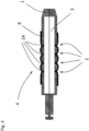
- the 1 shows a mandrel 1 according to the invention with four annular circumferential areas 2, the areas 2 being formed as segments 2A made of a sintered material and having an air-permeable wall.
- the airtight portions of the mandrel are formed of airtight wall segments 2B.
- the mandrel 1 is axially terminated by an airtight end piece 1A and 1B, respectively.
- the mandrel 1 also has an air chamber 3 .
- the air chamber 3 contains air at atmospheric pressure, with air exchange between the air chamber 3 and the environment being possible through the air-permeable areas 2 .
- the mandrel 1 also has a shaped contour 4 .
- FIG 2 the mandrel 1 is shown with a hose blank 5 attached.
- the mandrel 1 with the blank 5 is arranged in an autoclave, not shown here.
- the tube blank 5 is not in a form-fitting manner over the contour 4 of the mandrel 1, since the internal pressure of the air chamber 3 and the pressure in the autoclave, not shown, are still the same in the state shown. As a result, an air cushion 6 is enclosed between the mandrel 1 and the blank 5 .
- FIG 3 the mandrel 1 with blank 5 and mold contour 4 is shown in a state in which a vulcanization pressure generated by the autoclave (not shown), symbolized here by arrows 7, acts on the blank 5.
- This vulcanization pressure 7 is intended to cause the blank 5 to be pressed against the mold contour 4 of the mandrel 1 .
- the mandrel 1 is shown with a fully vulcanized hollow body 8 .
- the air previously enclosed in the original air cushion, which is no longer present here, has been displaced into the air chamber 3 by the segments 2A. Due to the pressure and temperature conditions prevailing in the autoclave (not shown), the blank is pressed against the mold contour 4 of the mandrel and finished to form the elastic hollow body 8 with a predetermined shape corresponding to the mold contour 4 of the mandrel 1 .
Landscapes
- Physics & Mathematics (AREA)
- Health & Medical Sciences (AREA)
- Oral & Maxillofacial Surgery (AREA)
- Thermal Sciences (AREA)
- Engineering & Computer Science (AREA)
- Mechanical Engineering (AREA)
- Heating, Cooling, Or Curing Plastics Or The Like In General (AREA)
- Moulds For Moulding Plastics Or The Like (AREA)
- Casting Or Compression Moulding Of Plastics Or The Like (AREA)
Description
- Die Erfindung betrifft ein Verfahren zur Herstellung eines geformten Hohlkörpers aus elastomerem Material.
- Hohlkörper, die neben ihrer Basisform weitere Formelemente aufweisen, werden häufig mittels einer Vulkanisationsvorrichtung geformt. Dabei weist ein Vulkanisationswerkzeug die Komplementärform des Fertigteils auf. Ein Rohling, beispielsweise ein extrudierter Schlauchendabschnitt, kann in dem Vulkanisationswerkzeug durch Beaufschlagung mit Druckluft an die Wandung des Werkzeugs gepresst und vulkanisiert werden. Auf diese Weise sind beispielsweise elastische Schläuche mit ringförmigen Wulsten herstellbar.
- Mit einem derartigen Verfahren kann jedoch pro Vulkanisationsvorgang nur jeweils eine begrenzte Anzahl von Teilen hergestellt werden, da jedes Teil einen Innendruck erzeugt, der von der jeweiligen Vulkanisationspresse aufzunehmen ist. Daher entscheidet die Schließkraft der Presse über die Menge der zeitgleich herstellbaren Teile, was die Ausbringung einschränken kann.
- Die
GB 1 167 146 A - Der Erfindung lag daher die Aufgabe zugrunde, ein Verfahren zur Herstellung der genannten Hohlkörper zu schaffen, das eine höhere Ausbringung ermöglicht.
- Diese Aufgabe wird durch ein Verfahren gemäß Anspruch 1 gelöst.
- Dieses Verfahren erlaubt es, mit einem Vulkanisationsprozess mehrere Hohlkörper auf einmal zu fertigen.
- In einer Weiterbildung der Erfindung weist das Verfahren mindestens folgenden weiteren Arbeitsschritt auf, nämlich
c1) Druckbeaufschlagung der Luftkammern der Dorne mit einem vorbestimmten Innendruck - Die Druckbeaufschlagung kann bei der Abstimmung der Prozesskräfte und der durch die luftdurchlässigen Bereiche der Dorne strömende Luftmenge hilfreich sein.
- In einer Weiterbildung der Erfindung weist das Verfahren mindestens folgenden weiteren Arbeitsschritt auf, nämlich
es) Druckanpassung zwischen den Luftkammern der Dorne und dem Autoklaven über einstellbare, in den Dornen angeordnete Druckausgleichselemente. - Auf diese Weise lassen sich die Prozessparameter, beispielsweise Viskosität des elastomeren Materials, und Luftdurchlässigkeit der Wandungsbereiche der Dorne oder die auftretenden Prozesskräfte auch in Abhängigkeit von der Prozesstemperatur gut berücksichtigen und aufeinander abstimmen.
- In einer Weiterbildung der Erfindung weist das Verfahren mindestens folgenden weiteren Arbeitsschritt auf, nämlich
f1) Druckbeaufschlagung der Luftkammern der Dorne, dadurch Durchtritt von Luft durch die luftdurchlässigen Wandungsbereiche aus den Luftkammern zwischen die Dorne und die fertig vulkanisierten Hohlkörper, dabei Bildung eines Luftpolsters zwischen Dornen und Hohlkörpern. - Diese Luftpolster können das Abziehen der Hohlkörper vom Dorn erleichtern.
- Die Erfindung betrifft weiter eine Vorrichtung zur Durchführung des oben erläuterten Verfahrens.
- Der Erfindung lag dabei die Aufgabe zugrunde, eine Vorrichtung zu schaffen, mit der das eingangs erläuterte Verfahren besonders einfach durchzuführen ist.
- Diese Aufgabe wird durch eine Vorrichtung gemäß Anspruch 4 gelöst.
- Derartige Dorne haben den Vorteil, dass sie in einem Autoklaven einsetzbar sind, wobei mehrere Dorne gleichzeitig in den Autoklaven einbringbar sind.
- Durch die luftdurchlässige Wandung ist Luft, die beim Aufstecken des Rohlings zwischen Dorn und Wand des Rohlings eingeschlossen wird, bei Druckbeaufschlagung des Autoklaven in die korrespondierenden Luftkammern der Dorne pressbar, sodass die Rohlinge an der Komplementärform des jeweiligen Dornes formschlüssig anliegen. Da die fertigen Hohlkörper aus Elastomermaterial sind, lassen sich diese bei vollendeter Vulkanisation und Druckentlastung des Autoklaven vom Dorn wieder abziehen.
- In einer Weiterbildung der Erfindung sind die Luftkammern der Dorne mit Druckluft beaufschlagbar.
- Nach Abschluss der Vulkanisation und Druckentlastung der Autoklaven kann so Luft durch die entsprechenden luftdurchlässigen Bereiche zwischen den Hohlkörper und den Dorn gepresst werden, wodurch ein Luftpolster zwischen dem Hohlkörper und dem Dorn bildbar ist, so das ein Abziehen der Hohlkörper vom Dorn erleichtert ist.
- In einer Weiterbildung der Erfindung weisen die Luftkammern der Dorne einstellbare Druckausgleichselemente auf.
- Mittels dieser Druckausgleichselemente ist der Differenzdruck zwischen dem Innendruck in den Luftkammern der Dorne und dem Autoklavendruck einstellbar.
- Auf diese Weise ist das Anlegen der Rohlingswand an die Dorne in Abhängigkeit von den sich gegebenenfalls ändernden Prozessparametern einstellbar. Es lässt sich beispielsweise vermeiden, dass das elastomere Material, welches sich bei Beaufschlagung mit Autoklavendruck und Hitze in seiner Viskosität ändert, aufgrund der geregelten Kraft, die auf den Schlauch wirkt, durch die luftdurchlässigen Bereiche der Domwandung in das Innere der Dorne gesaugt wird und dabei die luftdurchlässigen Bereiche der Dorne verstopft.
- In einer Weiterbildung der Erfindung sind die Dorne aus mindestens einem Segment luftdichter Wandung und mindestens einem Segment mit luftdurchlässiger Wandung zusammengesetzt, wobei die luftdichten Segmente mit luftdurchlässigen Segmenten in einer vorbestimmten Abfolge axial aufeinanderfolgend angeordnet sind.
- Die Segmentierung der Dorne hat den Vorteil, dass die einzelnen Segmente separat herstellbar sind, wobei das jeweilige Fertigungsverfahren auf den Anwendungsfall, nämlich entweder luftdichte oder luftdurchlässige Wandung der Segmente optimierbar ist.
- Gemäß der Erfindung sind die Segmente mit luftdurchlässiger Wandung aus einem Sintermaterial ausgebildet.
- Sintermaterial hat den Vorteil, dass einerseits die Porosität der Bereiche gut voreinstellbar ist, andererseits diese Materialien auch eine hohe Festigkeit und Temperaturbeständigkeit aufweisen.
- Anhand der Zeichnung wird nachstehend ein Ausführungsbeispiel der Erfindung näher erläutert.
- Die
Fig. 1 zeigt einen erfindungsgemäßen Dorn 1 mit vier ringförmig umlaufenden Bereichen 2, wobei die Bereiche 2 als Segmente 2A aus einem Sintermaterial ausgebildet sind und eine luftdurchlässige Wandung aufweisen. Die luftdichten Teile des Dornes sind aus Segmenten 2B mit luftdichter Wandung gebildet. Der Dorn 1 wird jeweils durch ein luftdichtes Endstück 1A und 1B axial abgeschlossen. - Der Dorn 1 weist weiter eine Luftkammer 3 auf. Die Luftkammer 3 enthält Luft mit Atmosphärendruck, wobei durch die luftdurchlässigen Bereiche 2 ein Luftaustausch zwischen der Luftkammer 3 und der Umgebung möglich ist.
- Der Dorn 1 weist weiterhin eine Formkontur 4 auf.
- In
Figur 2 ist der Dorn 1 mit einem aufgesteckten Schlauchrohling 5 dargestellt. Der Dorn 1 mit Rohling 5 ist in einem hier nicht dargestellten Autoklaven angeordnet. Der Schlauchrohling 5 liegt über der Formkontur 4 des Dorns 1 nicht formschlüssig an, da der Innendruck der Luftkammer 3 und der Druck im nicht gezeigten Autoklaven in dem gezeigten Zustand noch gleich sind. Dadurch ist ein Luftpolster 6 zwischen dem Dorn 1 und dem Rohling 5 eingeschlossen. - In
Figur 3 ist der Dorn 1 mit Rohling 5 und Formkontur 4 in einem Zustand gezeigt, in dem ein durch den nicht gezeigten Autoklaven erzeugter Vulkanisationsdruck, hier durch Pfeile 7 symbolisiert, auf den Rohling 5 einwirkt. Dieser Vulkanisationsdruck 7 soll bewirken, dass der Rohling 5 an die Formkontur 4 des Dorns 1 angepresst wird. - In
Fig. 4 ist der Dorn 1 mit einem fertig ausvulkanisierten Hohlkörper 8 gezeigt. Die in dem ursprünglichen, hier nicht mehr vorhandenen Luftpolster vorher eingeschlossene Luft ist durch die Segmente 2A in die Luftkammer 3 verschoben. Durch die im nicht gezeigten Autoklaven herrschenden Druck- und Temperaturverhältnisse ist der Rohling an die Formkontur 4 des Dornes angepresst und zu dem elastischen Hohlkörper 8 mit vorbestimmter, zur Formkontur 4 des Dornes 1 korrespondierender Form fertiggestellt. -
- 1
- Dorn
- 1A, 1B
- axiale Endstücke des Dornes 1
- 2
- luftdurchlässige Bereiche des Dorns 1
- 2A
- luftdurchlässige Segmente des Dorns 1
- 2B
- luftdichte Segmente des Dornes 1
- 3
- Luftkammer
- 4
- Formkontur des Dorns 1
- 5
- Schlauchrohling
- 6
- Luftpolster
- 7
- Vulkanisationsdruck
- 8
- vulkanisierter Hohlkörper
Claims (7)
- Verfahren zur Herstellung von geformten Hohlkörpern (8) aus elastomerem Material, wobei das Verfahren mindestens folgende Arbeitsschritte aufweist, nämlicha) Aufschieben eines vorgefertigten Rohlings (5) auf einen Dorn (1), wobei der Dorn (1) mindestens einen Bereich mit einer Wandung (2) aufweist, die luftdurchlässig ausgebildet ist, und der Dorn (1) mindestens eine Luftkammer (3) aufweist, die mit dem mindestens einen Bereich luftdurchlässiger Wandung (2, 2A) in Wirkverbindung steht,b) Einbringen des Dorns (1) mit aufgestecktem Rohling (5) in einen an sich bekannten Autoklaven,c1) Beaufschlagung des Autoklaven mit Druck und Temperatur, wobei Luft (6), die zwischen dem Rohlingen (5) und dem Dorn (1) eingeschlossen ist, durch die Bereiche luftdurchlässiger Wandung (2, 2A) in die jeweilige Luftkammer (3) gepresst wird, dabei Ausvulkanisation der Rohlinge (5),d) Entlastung des Autoklaven und Abkühlene) Entnehmen des Dorns (1) mit fertig vulkanisiertem und ausgeformtem Hohlkörper (8)f2) Abziehen des Hohlkörpers (8) von dem Dorn (1),dadurch gekennzeichnet, dass der mindestens eine Bereich luftdurchlässiger Wandung (2, 2A) als Segment aus einem porösen Sintermaterial ausgebildet ist.
- Verfahren nach Anspruch 1, dadurch gekennzeichnet, dass mindestens folgenden weiteren Arbeitsschritt aufweist, nämlich
c2) Druckanpassung zwischen der Luftkammer (3) des Dorns (1) und dem Autoklaven über ein einstellbares, in dem Dorn (1) angeordnetes Druckausgleichselement. - Verfahren nach Anspruch 1 oder 2, dadurch gekennzeichnet, dass das Verfahren mindestens folgenden weiteren Arbeitsschritt aufweist, nämlich
f1) Druckbeaufschlagung der Luftkammer (3) des Dorns (1), dadurch Durchtritt von Luft durch den oder die luftdurchlässigen Wandungsbereiche (2, 2A) aus der Luftkammer (3) zwischen den Dorn (1) und den fertig vulkanisierten Hohlkörper (8), dabei Bildung eines Luftpolsters zwischen Dorn (1) und Hohlkörper (8). - Vorrichtung zur Herstellung eines geformten Hohlkörpers (8), wobei die Vorrichtung mindestens einen Dorn (1) aufweist, auf den ein im wesentlichen schlauchförmig ausgebildetes Rohteil (5) aufsteckbar ist und der mindestens einen Bereich mit einer luftdurchlässigen Wandung (2, 2A) und mindestens eine Luftkammer (3) aufweist, wobei der mindestens eine Bereich mit luftdurchlässiger Wandung (2, 2A) mit jeweils mindestens einer Luftkammer (3) in Wirkverbindung steht und wobei der mindestens eine Dorn (1) die Komplementärform (4) zur vorbestimmten Endgeometrie des Hohlkörpers (8) aufweist,
dadurch gekennzeichnet, dass der mindestens eine Dorn axial aus Segmenten zusammengesetzt ist und dass der mindestens eine Bereich luftdurchlässiger Wandung als Segment aus einem porösen Material ausgebildet ist. - Vorrichtung nach Anspruch 4, dadurch gekennzeichnet, dass die Luftkammer (3) des Dorns (1) mit Druckluft beaufschlagbar sind.
- Vorrichtung nach Anspruch 4 oder 5, dadurch gekennzeichnet, dass die Luftkammer (3) des Dorns (1) ein einstellbares Druckausgleichselement aufweist.
- Vorrichtung nach Anspruch 4, 5 oder 6, dadurch gekennzeichnet, dass der Dorn (1) aus mindestens einem Segment (2B) luftdichter Wandung und mindestens einem Segment (2A) luftdurchlässiger Wandung zusammengesetzt sind, wobei die luftdichten Segmente (2B) mit luftdurchlässigen Segmenten (2A) in einer vorbestimmten Abfolge axial aufeinanderfolgend angeordnet sind.
Applications Claiming Priority (2)
| Application Number | Priority Date | Filing Date | Title |
|---|---|---|---|
| DE102017223307.9A DE102017223307A1 (de) | 2017-12-20 | 2017-12-20 | Verfahren zur Herstellung eines geformten Hohlkörpers und Vorrichtung zur Durchführung des Verfahrens |
| PCT/EP2018/077660 WO2019120668A1 (de) | 2017-12-20 | 2018-10-11 | Verfahren zur herstellung eines geformten hohlkörpers und vorrichtung zur durchführung des verfahrens |
Publications (2)
| Publication Number | Publication Date |
|---|---|
| EP3727780A1 EP3727780A1 (de) | 2020-10-28 |
| EP3727780B1 true EP3727780B1 (de) | 2023-09-06 |
Family
ID=63840850
Family Applications (1)
| Application Number | Title | Priority Date | Filing Date |
|---|---|---|---|
| EP18785938.4A Active EP3727780B1 (de) | 2017-12-20 | 2018-10-11 | Verfahren zur herstellung eines geformten hohlkörpers und vorrichtung zur durchführung des verfahrens |
Country Status (3)
| Country | Link |
|---|---|
| EP (1) | EP3727780B1 (de) |
| DE (1) | DE102017223307A1 (de) |
| WO (1) | WO2019120668A1 (de) |
Family Cites Families (7)
| Publication number | Priority date | Publication date | Assignee | Title |
|---|---|---|---|---|
| GB761212A (en) * | 1953-12-14 | 1956-11-14 | Dayton Rubber Company | Reinforced flexible conduits and method for manufacturing same |
| GB892654A (en) * | 1959-04-20 | 1962-03-28 | Dayco Corp | Reinforced flexible conduit |
| GB1167146A (en) * | 1965-11-25 | 1969-10-15 | Avon Rubber Company Ltd | Former. |
| US4298330A (en) * | 1981-08-06 | 1981-11-03 | Dayco Corporation | Curved mandrel for curing polymeric hose and method |
| CA2077400A1 (en) * | 1991-10-08 | 1993-04-09 | Mikhail Leyderman | Mandrel and a method of making a rigid tubular article |
| DE10354764A1 (de) * | 2003-11-21 | 2005-06-23 | Volkswagen Ag | Vorrichtung und Verfahren zur Herstellung eines Schlauchprofils, insbesondere eines Faltenbalges |
| DE102007044320B3 (de) * | 2007-09-17 | 2008-12-24 | Horst Dipl.-Ing. Huke | Kernwerkzeug zur Herstellung eines Hohlkörpers |
-
2017
- 2017-12-20 DE DE102017223307.9A patent/DE102017223307A1/de not_active Withdrawn
-
2018
- 2018-10-11 WO PCT/EP2018/077660 patent/WO2019120668A1/de not_active Ceased
- 2018-10-11 EP EP18785938.4A patent/EP3727780B1/de active Active
Also Published As
| Publication number | Publication date |
|---|---|
| DE102017223307A1 (de) | 2019-06-27 |
| WO2019120668A1 (de) | 2019-06-27 |
| EP3727780A1 (de) | 2020-10-28 |
Similar Documents
| Publication | Publication Date | Title |
|---|---|---|
| DE1071325B (de) | Verfahren zum befestigen von metallkappen an luftfederbälgen | |
| DE2659587A1 (de) | Elastischer formheizbalg fuer luftreifen sowie verfahren und vorrichtung zu dessen herstellung | |
| DE102007013096A1 (de) | Vorrichtung zum Behandeln von Behältnissen | |
| EP1407875B1 (de) | Ausformung von Luftfeder-Schlauchrollbälgen | |
| DE2538106C2 (de) | Verfahren und vorrichtung zur bildung einer muffe an einem rohrende und muffenrohr hergestellt nach diesem verfahren | |
| DE2523747C2 (de) | Verfahren und Vorrichtung zur Herstellung von Luftreifen | |
| AT398054B (de) | Verfahren und vorrichtung zur herstellung von kraftübertragungsriemen | |
| DE2210099C3 (de) | Verfahren und Vorrichtung zur Ausformung von Gegenständen aus wärmehärtenden Werkstoffen, insbesondere von Fahrzeugluftreifen | |
| EP3727781B1 (de) | Verfahren zur herstellung eines geformten hohlkörpers und vorrichtung zur durchführung des verfahrens | |
| EP3727779B1 (de) | Verfahren zur herstellung eines geformten hohlkörpers und vorrichtung zur durchführung des verfahrens | |
| EP3727782B1 (de) | Verfahren zur herstellung eines geformten hohlkörpers und vorrichtung zur durchführung des verfahrens | |
| DE102012112939A1 (de) | Vorrichtung und Verfahren zur Infiltration einer Faserpreform | |
| WO2019120668A1 (de) | Verfahren zur herstellung eines geformten hohlkörpers und vorrichtung zur durchführung des verfahrens | |
| DE102017130680B4 (de) | Matrize für eine Presse sowie Verfahren zur Herstellung mindestens eines Grünlings mit einer solchen Presse | |
| DE10302883B4 (de) | Vulkanisationsverfahren und Vulkanisationsvorrichtung mit Balg für PKW-Luftfedern | |
| DE1099156B (de) | In Pressvorrichtungen einsetzbare Vulkanisierform | |
| DE102012109711B4 (de) | Vorrichtung zum balglosen Vulkanisieren | |
| DE60102423T2 (de) | Verfahren und Vorrichtung zum Formen eines Stützkörpers | |
| EP2058113A2 (de) | Verfahren zum Herstellen bombierter, schlauchförmiger Erzeugnisse | |
| DE2203030C3 (de) | Verfahren und Vorrichtung zum Herstellen von Reifen aus gießfähigen Kunststoffen | |
| DE1120677B (de) | Verfahren und Einrichtung zum Verformen eines Balgrohlings fuer den Federkoerper einer Luftfeder | |
| DE1252409B (de) | Vorrichtung zum Formen eines ringförmigen Rohlauf Streifens | |
| WO2018050302A1 (de) | Verfahren zur balglosen vulkanisation sowie mehrteilige vulkanisationsform dafür | |
| WO2017097456A1 (de) | Vorrichtung zur herstellung von konusbälgen | |
| DE1779218A1 (de) | Verfahren zum Aufbau und Vulkanisieren von Guertelreifen |
Legal Events
| Date | Code | Title | Description |
|---|---|---|---|
| STAA | Information on the status of an ep patent application or granted ep patent |
Free format text: STATUS: UNKNOWN |
|
| STAA | Information on the status of an ep patent application or granted ep patent |
Free format text: STATUS: THE INTERNATIONAL PUBLICATION HAS BEEN MADE |
|
| PUAI | Public reference made under article 153(3) epc to a published international application that has entered the european phase |
Free format text: ORIGINAL CODE: 0009012 |
|
| STAA | Information on the status of an ep patent application or granted ep patent |
Free format text: STATUS: REQUEST FOR EXAMINATION WAS MADE |
|
| 17P | Request for examination filed |
Effective date: 20200720 |
|
| AK | Designated contracting states |
Kind code of ref document: A1 Designated state(s): AL AT BE BG CH CY CZ DE DK EE ES FI FR GB GR HR HU IE IS IT LI LT LU LV MC MK MT NL NO PL PT RO RS SE SI SK SM TR |
|
| AX | Request for extension of the european patent |
Extension state: BA ME |
|
| RAP1 | Party data changed (applicant data changed or rights of an application transferred) |
Owner name: CONTITECH MGW GMBH |
|
| DAV | Request for validation of the european patent (deleted) | ||
| DAX | Request for extension of the european patent (deleted) | ||
| STAA | Information on the status of an ep patent application or granted ep patent |
Free format text: STATUS: EXAMINATION IS IN PROGRESS |
|
| 17Q | First examination report despatched |
Effective date: 20221104 |
|
| RIC1 | Information provided on ipc code assigned before grant |
Ipc: B29C 33/46 20060101ALN20230328BHEP Ipc: B29C 33/42 20060101ALN20230328BHEP Ipc: B29C 33/76 20060101ALI20230328BHEP Ipc: B29D 23/00 20060101ALI20230328BHEP Ipc: B29C 35/02 20060101AFI20230328BHEP |
|
| GRAP | Despatch of communication of intention to grant a patent |
Free format text: ORIGINAL CODE: EPIDOSNIGR1 |
|
| STAA | Information on the status of an ep patent application or granted ep patent |
Free format text: STATUS: GRANT OF PATENT IS INTENDED |
|
| RIC1 | Information provided on ipc code assigned before grant |
Ipc: B29C 33/46 20060101ALN20230502BHEP Ipc: B29C 33/42 20060101ALN20230502BHEP Ipc: B29C 33/76 20060101ALI20230502BHEP Ipc: B29D 23/00 20060101ALI20230502BHEP Ipc: B29C 35/02 20060101AFI20230502BHEP |
|
| INTG | Intention to grant announced |
Effective date: 20230517 |
|
| GRAS | Grant fee paid |
Free format text: ORIGINAL CODE: EPIDOSNIGR3 |
|
| GRAA | (expected) grant |
Free format text: ORIGINAL CODE: 0009210 |
|
| STAA | Information on the status of an ep patent application or granted ep patent |
Free format text: STATUS: THE PATENT HAS BEEN GRANTED |
|
| P01 | Opt-out of the competence of the unified patent court (upc) registered |
Effective date: 20230724 |
|
| AK | Designated contracting states |
Kind code of ref document: B1 Designated state(s): AL AT BE BG CH CY CZ DE DK EE ES FI FR GB GR HR HU IE IS IT LI LT LU LV MC MK MT NL NO PL PT RO RS SE SI SK SM TR |
|
| REG | Reference to a national code |
Ref country code: GB Ref legal event code: FG4D Free format text: NOT ENGLISH |
|
| REG | Reference to a national code |
Ref country code: CH Ref legal event code: EP |
|
| REG | Reference to a national code |
Ref country code: DE Ref legal event code: R096 Ref document number: 502018013209 Country of ref document: DE |
|
| REG | Reference to a national code |
Ref country code: IE Ref legal event code: FG4D Free format text: LANGUAGE OF EP DOCUMENT: GERMAN |
|
| REG | Reference to a national code |
Ref country code: LT Ref legal event code: MG9D |
|
| REG | Reference to a national code |
Ref country code: NL Ref legal event code: MP Effective date: 20230906 |
|
| PG25 | Lapsed in a contracting state [announced via postgrant information from national office to epo] |
Ref country code: GR Free format text: LAPSE BECAUSE OF FAILURE TO SUBMIT A TRANSLATION OF THE DESCRIPTION OR TO PAY THE FEE WITHIN THE PRESCRIBED TIME-LIMIT Effective date: 20231207 |
|
| PG25 | Lapsed in a contracting state [announced via postgrant information from national office to epo] |
Ref country code: SE Free format text: LAPSE BECAUSE OF FAILURE TO SUBMIT A TRANSLATION OF THE DESCRIPTION OR TO PAY THE FEE WITHIN THE PRESCRIBED TIME-LIMIT Effective date: 20230906 Ref country code: RS Free format text: LAPSE BECAUSE OF FAILURE TO SUBMIT A TRANSLATION OF THE DESCRIPTION OR TO PAY THE FEE WITHIN THE PRESCRIBED TIME-LIMIT Effective date: 20230906 Ref country code: NO Free format text: LAPSE BECAUSE OF FAILURE TO SUBMIT A TRANSLATION OF THE DESCRIPTION OR TO PAY THE FEE WITHIN THE PRESCRIBED TIME-LIMIT Effective date: 20231206 Ref country code: LV Free format text: LAPSE BECAUSE OF FAILURE TO SUBMIT A TRANSLATION OF THE DESCRIPTION OR TO PAY THE FEE WITHIN THE PRESCRIBED TIME-LIMIT Effective date: 20230906 Ref country code: LT Free format text: LAPSE BECAUSE OF FAILURE TO SUBMIT A TRANSLATION OF THE DESCRIPTION OR TO PAY THE FEE WITHIN THE PRESCRIBED TIME-LIMIT Effective date: 20230906 Ref country code: HR Free format text: LAPSE BECAUSE OF FAILURE TO SUBMIT A TRANSLATION OF THE DESCRIPTION OR TO PAY THE FEE WITHIN THE PRESCRIBED TIME-LIMIT Effective date: 20230906 Ref country code: GR Free format text: LAPSE BECAUSE OF FAILURE TO SUBMIT A TRANSLATION OF THE DESCRIPTION OR TO PAY THE FEE WITHIN THE PRESCRIBED TIME-LIMIT Effective date: 20231207 Ref country code: FI Free format text: LAPSE BECAUSE OF FAILURE TO SUBMIT A TRANSLATION OF THE DESCRIPTION OR TO PAY THE FEE WITHIN THE PRESCRIBED TIME-LIMIT Effective date: 20230906 |
|
| PG25 | Lapsed in a contracting state [announced via postgrant information from national office to epo] |
Ref country code: NL Free format text: LAPSE BECAUSE OF FAILURE TO SUBMIT A TRANSLATION OF THE DESCRIPTION OR TO PAY THE FEE WITHIN THE PRESCRIBED TIME-LIMIT Effective date: 20230906 |
|
| PG25 | Lapsed in a contracting state [announced via postgrant information from national office to epo] |
Ref country code: IS Free format text: LAPSE BECAUSE OF FAILURE TO SUBMIT A TRANSLATION OF THE DESCRIPTION OR TO PAY THE FEE WITHIN THE PRESCRIBED TIME-LIMIT Effective date: 20240106 |
|
| PG25 | Lapsed in a contracting state [announced via postgrant information from national office to epo] |
Ref country code: ES Free format text: LAPSE BECAUSE OF FAILURE TO SUBMIT A TRANSLATION OF THE DESCRIPTION OR TO PAY THE FEE WITHIN THE PRESCRIBED TIME-LIMIT Effective date: 20230906 |
|
| PG25 | Lapsed in a contracting state [announced via postgrant information from national office to epo] |
Ref country code: SM Free format text: LAPSE BECAUSE OF FAILURE TO SUBMIT A TRANSLATION OF THE DESCRIPTION OR TO PAY THE FEE WITHIN THE PRESCRIBED TIME-LIMIT Effective date: 20230906 Ref country code: RO Free format text: LAPSE BECAUSE OF FAILURE TO SUBMIT A TRANSLATION OF THE DESCRIPTION OR TO PAY THE FEE WITHIN THE PRESCRIBED TIME-LIMIT Effective date: 20230906 Ref country code: IS Free format text: LAPSE BECAUSE OF FAILURE TO SUBMIT A TRANSLATION OF THE DESCRIPTION OR TO PAY THE FEE WITHIN THE PRESCRIBED TIME-LIMIT Effective date: 20240106 Ref country code: ES Free format text: LAPSE BECAUSE OF FAILURE TO SUBMIT A TRANSLATION OF THE DESCRIPTION OR TO PAY THE FEE WITHIN THE PRESCRIBED TIME-LIMIT Effective date: 20230906 Ref country code: EE Free format text: LAPSE BECAUSE OF FAILURE TO SUBMIT A TRANSLATION OF THE DESCRIPTION OR TO PAY THE FEE WITHIN THE PRESCRIBED TIME-LIMIT Effective date: 20230906 Ref country code: CZ Free format text: LAPSE BECAUSE OF FAILURE TO SUBMIT A TRANSLATION OF THE DESCRIPTION OR TO PAY THE FEE WITHIN THE PRESCRIBED TIME-LIMIT Effective date: 20230906 Ref country code: SK Free format text: LAPSE BECAUSE OF FAILURE TO SUBMIT A TRANSLATION OF THE DESCRIPTION OR TO PAY THE FEE WITHIN THE PRESCRIBED TIME-LIMIT Effective date: 20230906 Ref country code: PT Free format text: LAPSE BECAUSE OF FAILURE TO SUBMIT A TRANSLATION OF THE DESCRIPTION OR TO PAY THE FEE WITHIN THE PRESCRIBED TIME-LIMIT Effective date: 20240108 |
|
| PG25 | Lapsed in a contracting state [announced via postgrant information from national office to epo] |
Ref country code: PL Free format text: LAPSE BECAUSE OF FAILURE TO SUBMIT A TRANSLATION OF THE DESCRIPTION OR TO PAY THE FEE WITHIN THE PRESCRIBED TIME-LIMIT Effective date: 20230906 Ref country code: IT Free format text: LAPSE BECAUSE OF FAILURE TO SUBMIT A TRANSLATION OF THE DESCRIPTION OR TO PAY THE FEE WITHIN THE PRESCRIBED TIME-LIMIT Effective date: 20230906 |
|
| REG | Reference to a national code |
Ref country code: CH Ref legal event code: PL |
|
| REG | Reference to a national code |
Ref country code: DE Ref legal event code: R097 Ref document number: 502018013209 Country of ref document: DE |
|
| REG | Reference to a national code |
Ref country code: BE Ref legal event code: MM Effective date: 20231031 |
|
| PG25 | Lapsed in a contracting state [announced via postgrant information from national office to epo] |
Ref country code: LU Free format text: LAPSE BECAUSE OF NON-PAYMENT OF DUE FEES Effective date: 20231011 |
|
| REG | Reference to a national code |
Ref country code: DE Ref legal event code: R081 Ref document number: 502018013209 Country of ref document: DE Owner name: CONTITECH TECHNO-CHEMIE GMBH, DE Free format text: FORMER OWNER: CONTITECH MGW GMBH, 34346 HANN. MUENDEN, DE |
|
| PG25 | Lapsed in a contracting state [announced via postgrant information from national office to epo] |
Ref country code: LU Free format text: LAPSE BECAUSE OF NON-PAYMENT OF DUE FEES Effective date: 20231011 |
|
| PG25 | Lapsed in a contracting state [announced via postgrant information from national office to epo] |
Ref country code: MC Free format text: LAPSE BECAUSE OF FAILURE TO SUBMIT A TRANSLATION OF THE DESCRIPTION OR TO PAY THE FEE WITHIN THE PRESCRIBED TIME-LIMIT Effective date: 20230906 |
|
| PG25 | Lapsed in a contracting state [announced via postgrant information from national office to epo] |
Ref country code: DK Free format text: LAPSE BECAUSE OF FAILURE TO SUBMIT A TRANSLATION OF THE DESCRIPTION OR TO PAY THE FEE WITHIN THE PRESCRIBED TIME-LIMIT Effective date: 20230906 |
|
| PLBE | No opposition filed within time limit |
Free format text: ORIGINAL CODE: 0009261 |
|
| STAA | Information on the status of an ep patent application or granted ep patent |
Free format text: STATUS: NO OPPOSITION FILED WITHIN TIME LIMIT |
|
| PG25 | Lapsed in a contracting state [announced via postgrant information from national office to epo] |
Ref country code: CH Free format text: LAPSE BECAUSE OF NON-PAYMENT OF DUE FEES Effective date: 20231031 |
|
| PG25 | Lapsed in a contracting state [announced via postgrant information from national office to epo] |
Ref country code: MC Free format text: LAPSE BECAUSE OF FAILURE TO SUBMIT A TRANSLATION OF THE DESCRIPTION OR TO PAY THE FEE WITHIN THE PRESCRIBED TIME-LIMIT Effective date: 20230906 Ref country code: DK Free format text: LAPSE BECAUSE OF FAILURE TO SUBMIT A TRANSLATION OF THE DESCRIPTION OR TO PAY THE FEE WITHIN THE PRESCRIBED TIME-LIMIT Effective date: 20230906 Ref country code: CH Free format text: LAPSE BECAUSE OF NON-PAYMENT OF DUE FEES Effective date: 20231031 Ref country code: SI Free format text: LAPSE BECAUSE OF FAILURE TO SUBMIT A TRANSLATION OF THE DESCRIPTION OR TO PAY THE FEE WITHIN THE PRESCRIBED TIME-LIMIT Effective date: 20230906 |
|
| 26N | No opposition filed |
Effective date: 20240607 |
|
| PG25 | Lapsed in a contracting state [announced via postgrant information from national office to epo] |
Ref country code: BE Free format text: LAPSE BECAUSE OF NON-PAYMENT OF DUE FEES Effective date: 20231031 |
|
| PG25 | Lapsed in a contracting state [announced via postgrant information from national office to epo] |
Ref country code: IE Free format text: LAPSE BECAUSE OF NON-PAYMENT OF DUE FEES Effective date: 20231011 |
|
| PG25 | Lapsed in a contracting state [announced via postgrant information from national office to epo] |
Ref country code: IE Free format text: LAPSE BECAUSE OF NON-PAYMENT OF DUE FEES Effective date: 20231011 |
|
| PG25 | Lapsed in a contracting state [announced via postgrant information from national office to epo] |
Ref country code: BG Free format text: LAPSE BECAUSE OF FAILURE TO SUBMIT A TRANSLATION OF THE DESCRIPTION OR TO PAY THE FEE WITHIN THE PRESCRIBED TIME-LIMIT Effective date: 20230906 |
|
| PG25 | Lapsed in a contracting state [announced via postgrant information from national office to epo] |
Ref country code: BG Free format text: LAPSE BECAUSE OF FAILURE TO SUBMIT A TRANSLATION OF THE DESCRIPTION OR TO PAY THE FEE WITHIN THE PRESCRIBED TIME-LIMIT Effective date: 20230906 |
|
| REG | Reference to a national code |
Ref country code: AT Ref legal event code: MM01 Ref document number: 1607917 Country of ref document: AT Kind code of ref document: T Effective date: 20231011 |
|
| PG25 | Lapsed in a contracting state [announced via postgrant information from national office to epo] |
Ref country code: AT Free format text: LAPSE BECAUSE OF NON-PAYMENT OF DUE FEES Effective date: 20231011 |
|
| PG25 | Lapsed in a contracting state [announced via postgrant information from national office to epo] |
Ref country code: AT Free format text: LAPSE BECAUSE OF NON-PAYMENT OF DUE FEES Effective date: 20231011 |
|
| REG | Reference to a national code |
Ref country code: GB Ref legal event code: 732E Free format text: REGISTERED BETWEEN 20250109 AND 20250115 |
|
| PG25 | Lapsed in a contracting state [announced via postgrant information from national office to epo] |
Ref country code: CY Free format text: LAPSE BECAUSE OF FAILURE TO SUBMIT A TRANSLATION OF THE DESCRIPTION OR TO PAY THE FEE WITHIN THE PRESCRIBED TIME-LIMIT; INVALID AB INITIO Effective date: 20181011 |
|
| PG25 | Lapsed in a contracting state [announced via postgrant information from national office to epo] |
Ref country code: HU Free format text: LAPSE BECAUSE OF FAILURE TO SUBMIT A TRANSLATION OF THE DESCRIPTION OR TO PAY THE FEE WITHIN THE PRESCRIBED TIME-LIMIT; INVALID AB INITIO Effective date: 20181011 |
|
| PG25 | Lapsed in a contracting state [announced via postgrant information from national office to epo] |
Ref country code: TR Free format text: LAPSE BECAUSE OF FAILURE TO SUBMIT A TRANSLATION OF THE DESCRIPTION OR TO PAY THE FEE WITHIN THE PRESCRIBED TIME-LIMIT Effective date: 20230906 |
|
| PGFP | Annual fee paid to national office [announced via postgrant information from national office to epo] |
Ref country code: DE Payment date: 20251020 Year of fee payment: 8 |
|
| PGFP | Annual fee paid to national office [announced via postgrant information from national office to epo] |
Ref country code: GB Payment date: 20251022 Year of fee payment: 8 |
|
| PGFP | Annual fee paid to national office [announced via postgrant information from national office to epo] |
Ref country code: FR Payment date: 20251024 Year of fee payment: 8 |