EP3727608B1 - Fire extinguisher plant using water - Google Patents
Fire extinguisher plant using water Download PDFInfo
- Publication number
- EP3727608B1 EP3727608B1 EP18836418.6A EP18836418A EP3727608B1 EP 3727608 B1 EP3727608 B1 EP 3727608B1 EP 18836418 A EP18836418 A EP 18836418A EP 3727608 B1 EP3727608 B1 EP 3727608B1
- Authority
- EP
- European Patent Office
- Prior art keywords
- fire extinguisher
- water
- primary
- devices
- relaunch
- Prior art date
- Legal status (The legal status is an assumption and is not a legal conclusion. Google has not performed a legal analysis and makes no representation as to the accuracy of the status listed.)
- Active
Links
Images




Classifications
-
- A—HUMAN NECESSITIES
- A62—LIFE-SAVING; FIRE-FIGHTING
- A62C—FIRE-FIGHTING
- A62C35/00—Permanently-installed equipment
- A62C35/20—Hydrants, e.g. wall-hoses, wall units, plug-in cabinets
-
- A—HUMAN NECESSITIES
- A62—LIFE-SAVING; FIRE-FIGHTING
- A62C—FIRE-FIGHTING
- A62C3/00—Fire prevention, containment or extinguishing specially adapted for particular objects or places
-
- A—HUMAN NECESSITIES
- A62—LIFE-SAVING; FIRE-FIGHTING
- A62C—FIRE-FIGHTING
- A62C35/00—Permanently-installed equipment
- A62C35/58—Pipe-line systems
Definitions
- the present invention concerns a fire extinguisher or fire-fighting plant, and in particular a fire extinguisher plant using water, with a multiple-development network that is dry and above-ground.
- the present fire extinguisher plant is particularly suitable to be installed and used in outdoor or indoor areas of large structures.
- large structures is understood to include, by way of non-restrictive example, airports, railway stations, marine stations, subways, wholly or partly underground, freight terminals, rolling stock depots, docks in ports, wharves, industrial activities and in all activities at pre-eminent risk of fire, or other.
- pressurized water supply pipes although buried, may not be desired as this can cause problems of water leaks, or can be a source of potential safety problems, for example due to proximity with electricity lines. From another point of view, however, it is necessary to guarantee an easy, rapid and consistent availability of water needed to cope with a possible massive fire.
- the platforms or floors of large structures such as the railway platforms or floors of a train or marine station, or extensive areas where fuel is stored are considered areas of fire risk due to the domino effects that can arise as a result of a fire that affects one or more wagons that make up the convoy of public railway transport, of one or more moored vessels, close to each other, or of stacked combustible goods.
- these effects can also lead to the structural collapse of the roofing, usually made of metal structures or other, if they are put to protect users and workers from meteorological events.
- non-invasive solutions In order to overcome these disadvantages and conditions, non-invasive solutions must be used, which are easy to assemble, have a low cost or can be amortized over a reasonable period of time, and are proven to be effective in combating fires.
- one purpose of the present invention is to provide a fire extinguisher plant using water, with a dry network, above the ground, that is configured as an active fire protection system able to fulfill the function of effectively combating the starts of fires and fires in general with immediate availability of substantial volumes of water to fight the fires that can be used even before the arrival of the institutional operators responsible for combating fires.
- one purpose of the present invention is also to create a fire extinguisher plant using water that requires a time to extend it along the platform affected by the fire which is far shorter than that needed to insulate the electric power line and then to pass, almost instantly, from its dry condition to its wet condition, in order to start the fire extinguisher operations.
- Another purpose of the present invention is to provide a fire extinguisher plant using water, with a dry network, above the ground, that does not require the laying of underground water supply pipes, thus eliminating the costs of constructing an underground water network, and ensuring a significant water power as required, and more than sufficient to extinguish a fire that develops on any section of the entire surface served by the plant.
- Another purpose of the present invention is to provide a fire extinguisher plant using water, with a dry and above-ground network, provided with fire extinguisher devices or stations which can be quickly installed without any interference with public service and transport.
- Another purpose of the present invention is to provide a fire extinguisher plant using water which does not interfere with other networks, buried or not, of plants serving the structure in which the fire extinguisher plant according to the invention is installed.
- Another purpose of the present invention is to provide a fire extinguisher plant using water, with a dry network, above the ground, which can overcome possible historical-architectural constraints to which the structure on which it is to be disposed may be subjected, in order not to damage pre-existing works, for example, a flooring of historical value or other.
- Another purpose of the present invention is to provide a fire extinguisher plant using water, with a dry and above-ground network, which, given its flexibility, simplicity and efficiency, can be installed in a non-invasive, safe, economical and non-disfiguring manner in any large structure whatsoever.
- the Applicant has devised, tested and embodied the present invention to overcome the shortcomings of the state of the art and to obtain these and other purposes and advantages.
- Embodiments of the present invention concern a fire extinguisher plant, in particular with a dry, multiple development network, outside the ground and fed by water.
- the fire extinguisher plant according to the invention is particularly suitable for installation on floors of large structures such as airports, train stations, marine terminals and subway stations, either wholly or partly underground, or other.
- the fire extinguisher plant comprises:
- the secondary fire extinguisher devices are able to be connected at least in sequence starting from the primary fire extinguisher device by means of the dry water-relaunch pipes.
- the dry water-relaunch pipe of the primary fire extinguisher device is configured to deliver water to the dry water-relaunch pipes of the secondary fire extinguisher devices starting from the primary fire extinguisher device and as far as the hydrant or hydrants of at least one secondary fire extinguisher device nearest to a fire zone or start of fire.
- a dry water-relaunch pipe can connect two successive fire extinguisher devices, for example a primary fire extinguisher devices and a secondary fire extinguisher devices, or two secondary fire extinguisher devices put in succession.
- the at least one primary fire extinguisher device and the secondary fire extinguisher devices are disposed in sequence along a predefined trajectory or path.
- the at least one primary fire extinguisher device is installed in correspondence with a first end of the trajectory or path, while the secondary fire extinguisher devices are located in sequence along the trajectory.
- another primary fire extinguisher device is present, opposite the primary one at the first end of the trajectory, and located in any section of the trajectory, for example at one end, or head, or in an intermediate position.
- the first end of the plant can comprise connection means, configured to connect the water supply network to the primary fire extinguisher device, that is, the first end of the plant corresponds with the end that connects to the water supply network.
- the first end of the plant can be positioned in correspondence with a peripheral edge, on which vehicles can pass, of a floor of the structure. This allows, for example, a fire-fighting vehicle, if the need arises, to easily reach the first end and supply the entire plant directly.
- the plant according to the present invention comprises at least two primary fire extinguisher devices, one of which is provided in correspondence with a first end and the other in a second end of a positioning trajectory or path of the secondary fire extinguisher devices.
- Respective secondary fire extinguisher devices can be connected to each of the primary fire extinguisher devices, to define two sequences of secondary fire extinguisher devices.
- the fire extinguisher plant can comprise a plurality of ends in each of which there is a mean to connect to the water supply network.
- a respective primary fire extinguisher device is installed which, in turn, can be connected by means of the dry water-relaunch pipes to the secondary fire extinguisher devices, thus defining more sequences of secondary fire extinguisher devices each connected to a primary fire extinguisher device.
- a plurality of fire extinguisher devices are able to be selectively connected to the at least one primary fire extinguisher device, in order to define a network or grid of secondary fire extinguishers that branch off from the single primary fire extinguisher device in different directions.
- the primary fire extinguisher device is provided with one or more hydrants for the direct delivery of water and with at least one interception valve configured to selectively intercept the feed of water toward the hydrants and toward the respective dry water-relaunch pipe.
- the interception valve of the primary fire extinguisher devices can not only be activated manually, but can also be driven remotely, for example by means of a command disposed on the secondary fire extinguisher devices and/or by a command supplied by a central command unit, and on condition that it has received a consent signal, for example from an operator, or from a light and/or acoustic indicator.
- the interception valve for redundancy requirements, can be activated simultaneously in manual and remote mode.
- the primary fire extinguisher device and the secondary fire extinguisher device comprise at least one casing in which the respective dry water-relaunch pipe is housed.
- Another purpose of the invention concerns a fire extinguisher method using a fire-extinguisher plant as above and comprising:
- a fire-extinguisher or fire extinguisher plant 20 comprises at least one primary fire extinguisher device 21 which can be installed on a floor 22 of a structure.
- the floor 22 can define, for example, a platform of a railway station.
- the fire extinguisher plant 20 can also comprise a plurality of secondary fire extinguisher devices 26 1 -26 z , selectively connected hydraulically to each other and to one or more primary fire extinguisher devices 21 according to the methods described below.
- the at least one primary fire extinguisher device 21 and the secondary fire extinguisher devices 26 1 -26 z can be disposed in sequence along a predefined trajectory, or path.
- the at least one primary fire extinguisher device 21 and the secondary fire extinguisher devices 26 1 -26 z are reciprocally distanced from each other, at intervals of distances I along the trajectory or path. These ranges of distances I can be substantially all the same.
- the intervals of distances I between secondary fire extinguisher devices 26 1 -26 z and/or between the primary fire extinguisher device 21 and the first secondary fire extinguisher device 26 1 -26 z can vary according to different requirements, possible structural obstacles and the planimetric configuration of the infrastructure.
- the trajectory or path can be provided with a first end 27 and a second end 28 which can be distinguished from one another, identifying an open path, or they can be coincident, identifying a closed path.
- the trajectory or path has a length L ( figs. 1 and 2 ) and along the length L there is at least one primary fire extinguisher device 21 and the secondary fire extinguisher devices 26.
- the trajectory or path can have a rectilinear configuration, bent in segments, curvilinear or mixed rectilinear and curvilinear depending on the particular embodiment of the structure in which the fire extinguisher plant 20 according to the invention is installed.
- the at least one primary fire extinguisher device 21 can be installed in correspondence with the first end 27 of the trajectory or path, and the secondary fire extinguisher devices 26 are located in subsequent sequence along the trajectory or path, for example from the first secondary fire extinguisher device 26 1 to the last secondary fire extinguisher devices 26 z , located in succession between them starting from the primary fire extinguisher device 21.
- the last secondary device 26 z is instead located near the second end 28 opposite to that in which the primary fire extinguisher device 21 is positioned.
- the fire extinguisher plant 20 can comprise at least two primary fire extinguisher devices 21 1 and 21 2 , one of which is provided respectively in correspondence with the first end 27 and the other is provided in the second end 28.
- the secondary fire extinguisher devices 26 1 -26 z are connected to each of the primary fire extinguisher devices 21 1 and 21 2 to define two sequences of secondary fire extinguisher devices 26 1 -26 z .
- a plurality of secondary fire extinguisher devices 26 can be selectively connected to the same primary fire extinguisher device 21, to define a network or grid of secondary fire extinguisher devices 26 which branches off from the sole primary fire extinguisher device 21 in a star configuration, that is, in different directions.
- the primary fire extinguisher device 21 is configured to rotate around its own axis of rotation to orient itself according to a plurality of stellar development trajectories, along which trajectories one or more secondary fire extinguisher devices 26 are installed.
- the primary fire extinguisher device 21 comprises at least one casing 29, defining at least one compartment to house its components.
- the casing 29 can comprise a base 30 configured to allow it to be attached to the floor 22, for example by means of removable attachment elements such as bolts or suchlike.
- the primary fire extinguisher device 21 is connected to a water supply network 25 configured to supply the water.
- the primary fire extinguisher device 21 is provided with a tubular element 31 connected to the water supply network 25, for example by connection means.
- connection means can comprise sleeves, shutters, valves, or suchlike.
- the tubular element 31 is positioned at least partly in the casing 29.
- the tubular element 31 is provided with interception means, such as an interception valve 35 configured to selectively intercept the flow of water coming from the water supply network 25.
- interception means such as an interception valve 35 configured to selectively intercept the flow of water coming from the water supply network 25.
- the interception valve 35 can be drivable manually as shown in the drawings, or it can be electrically driven, for example remotely, or with a suitable electric command line.
- the interception valve 35 can comprise a lever 36, possibly installed at least partly protruding from the casing 29 and selectively drivable to allow the passage of water from the water supply network 25 to the primary fire extinguisher device 21.
- the interception valve 35 can be driven, also in wireless mode, with a button 37, or other command possibly installed in the secondary fire extinguisher devices 26 (see figs. 10 and 15 ) as better described hereafter in the description.
- the button 37 can be a lock-type button, that is, it can be activated with a suitable key available to specialized operators, encoded or suchlike.
- the opening of the interception valve 35 is conditioned by the activation of the button 37 and the lever 36.
- the tubular element 31 is connected, for example with a connector 32, to at least one other tubular element 33, in this case two tubular elements 33, to each of which a respective hydrant 34 can be selectively connected, and can be used to deliver a jet of water in the event of fire.
- the two tubular elements 33 can be provided with an interception device 33a, for example a shutter that can be selectively opened/closed to allow the passage of water.
- Each hydrant 34 can comprise a hose and possibly water delivery lances, associated with the hose, which are selectively connectable fluidically to the tubular elements 33.
- the primary fire extinguisher device comprises two hydrants 34, of the wall type, possibly UNI 45.
- the primary fire extinguisher device comprises a single hydrant 34, of the wall-mounted type, possibly UNI 45.
- the at least one hydrant 34 is positioned in the casing 29, for example in a box 39 of the latter.
- the casing 29 can be provided with doors 70 that can be selectively opened/closed, to allow access inside the casing 29.
- the casing 29 can also comprise other boxes 39 in which at least one of one or more extinguishers 40, one or more hoses 41 ( figs 7-9 , 20 ) are housed, the functions of which will be described hereafter.
- the primary fire extinguisher device 21 comprises two extinguishers 40.
- the primary fire extinguisher device 21 comprises a single fire extinguisher 40 and a relaunch hose 41.
- the relaunch hoses can have a diameter of 70mm.
- the casing 29 can be provided with corresponding doors 42 for access to the other boxes 39.
- the primary fire extinguisher device 21 is equipped with at least one flexible dry water-relaunch pipe 24, configured to be hydraulically connected to the water supply network 25 through the tubular element 31.
- water-relaunch pipe means a flexible pipe suitable to connect, in a selective manner, two fire extinguisher devices 21, or 26.
- dry referring to the water-relaunch pipe, we mean a condition in which the pipe, in its condition of non-use, does not contain water inside it, while in its condition of use, pressurized water is fed through it.
- the dry water-relaunch pipe 24 in its condition of non-use can be wound in coils, while in its condition of use, it is completely unrolled.
- the dry water-relaunch pipe 24 is housed in the casing 29.
- the casing 29 is provided with a compartment 62 in which the dry water-relaunch pipe 24 is disposed.
- the compartment 62 can be selectively opened/closed by means of a corresponding door 63.
- the casing 29 can be provided with an aperture 52 through which at least one first end of the dry water-relaunch pipe 24 protrudes.
- the dry water-relaunch end 24 can be provided with a connector 53 configured to allow its connection, for example, to one of the secondary fire extinguisher devices 26, or, by means of possible reducers or distributors, to lances that deliver a jet of water, or respectively to other hoses to deliver the water jet.
- the connector 53 can be the rapid type, for example the Storz type.
- the connector 53 can be selected from a group including a bayonet or threaded. According to one solution, the connector 53 can be the female type.
- the dry water-relaunch pipe 24 can be connected to the tubular element 31 by at least one pipe 43.
- the pipe 43 can be connected hydraulically to one end of the water-relaunch pipe 24.
- the primary fire extinguisher device 21 can comprise a winding device 44 configured to wind the dry water-relaunch pipe 24 around it.
- the winding device 44 can comprise a toothed disc 45 associated with a feed pawl 46 configured to prevent and/or allow the controlled unwinding of the dry water-relaunch pipe 24 from the winding device 44.
- the winding device 44 can be associated with a clamp and release lever 47, possibly cooperating with the toothed disc 45 and configured to selectively clamp the rotation of the winding device 44, thus preventing an involuntary unwinding of the dry water-relaunch pipe 24.
- the lever 47 can be manually drivable.
- the lever 47 can be coupled with an interception member 71, for example a tap, installed along the pipe 43 connecting the tubular element 31 to the dry water-relaunch pipe 24.
- an interception member 71 for example a tap
- the lever 47 prevents the winding device 44 from unwinding the dry water-relaunch pipe 24, and keeps the interception member 71 in a closed condition, preventing the passage of water.
- the primary fire extinguisher device 21 is provided with at least two dry water-relaunch pipes 24 each of which is wound on a respective winding device 44 as defined above.
- the ends of the dry water-relaunch pipe 24 provided with the connector 53 can be located protruding from opposite ends of the casing 29, and a first winding device 44 allows to unwind the dry water-relaunch pipe 24 in a clockwise direction while the other allows counter-clockwise unwinding.
- This solution can be used to connect the primary fire extinguisher device 21 to two secondary fire extinguisher devices 26 which are distanced from the primary one in different directions.
- the water-relaunch pipe 24 of the primary fire extinguisher device 21, if necessary, is therefore unwound and used to hydraulically connect at least a first secondary fire extinguisher devices 26 1 located in succession to the primary fire extinguisher device 21.
- the water supplied by the water supply network 25 can be made to pass through the primary fire extinguisher device 21, its water-relaunch pipe 24, and made available to the secondary fire extinguisher devices 26 1 .
- connection means 72 selectively connectable, during use, to an auxiliary water supply source, such as a fire-fighting vehicle, a tanker, or suchlike.
- connection means 72 are hydraulically connected to the dry water-relaunch pipe 24, 24' to allow to supply water to the latter.
- connection means 72 can be interposed along a connection pipe to the dry water-relaunch pipe 24, 24'.
- connection means 72 are associated with the primary fire extinguisher device 21, it can be provided that the connection means 72 are connected along the extension of the tubular element 31 for connection to the water supply network 25.
- connection means 72 can comprise a tubular segment 73 which connects to the tubular element 31.
- connection means 72 can be installed directly upstream of the interception valve 35.
- connection means 72 can be provided with an interception member 77, for the selective opening/closing of the passage of water.
- connection means 72 can also comprise, integrated in or associated with them, a flow interception member 74, for example a one-directional valve, an interception valve, or a multi-way valve, configured to allow the flow of water from the auxiliary water supply source only toward the respective dry water-relaunch pipe 24, 24', and not in the opposite direction, that is, toward the water supply network 25 or another secondary fire extinguisher device 26.
- a flow interception member 74 for example a one-directional valve, an interception valve, or a multi-way valve, configured to allow the flow of water from the auxiliary water supply source only toward the respective dry water-relaunch pipe 24, 24', and not in the opposite direction, that is, toward the water supply network 25 or another secondary fire extinguisher device 26.
- the primary fire extinguisher device 21b ( fig. 20 ) and/or possibly at least one of the secondary fire extinguisher devices 26, can comprise water discharge means interposed along the pipe, for example the pipe 43, which feeds water toward the respective dry water-relaunch pipe 24.
- the discharge means 75 allow to discharge any residual water present in the pipe following any fire extinguishing intervention.
- the discharge means 75 can comprise a tubular segment possibly governed by a corresponding opening and closing tap 76.
- the discharge means 75 are located downstream of the interception valve 35.
- a presser device can be associated with the winding device 44, such as a water scraper 48 configured to flatten the dry water-relaunch pipe 24 as it is wound around the winding device 44 and to eliminate possible residual water present in the pipe itself.
- a water scraper 48 configured to flatten the dry water-relaunch pipe 24 as it is wound around the winding device 44 and to eliminate possible residual water present in the pipe itself.
- the presser device or water scraper, can comprise a pair of opposite rollers 49 between which the dry water-relaunch pipe 24 is made to pass, during use.
- the rollers 49 can be associated with elastic elements 50 configured to press the rollers 49 against each other so as to flatten the dry water-relaunch pipe 24.
- the water pressure exceeds the force of the elastic elements 50, allowing the water to pass.
- the secondary fire extinguisher device 26 similar to the primary fire extinguisher device 21, can also comprise a casing 29' ( figs. 10-19 ) defining at least one compartment to house the respective operating components.
- the secondary fire extinguisher device 26 can simply be fixed to the floor 22, by means of bolts or suchlike.
- the secondary fire extinguisher device 26 can be substantially the same as the primary fire extinguisher device 21 described above, except that the secondary fire extinguisher device 26 is not connected to the water supply network 25.
- the at least one secondary fire extinguisher device 26 also comprises a dry water-relaunch pipe 24' substantially similar to the dry water-relaunch pipe described above with reference to the primary fire extinguisher device 21.
- the dry water-relaunch pipe 24' of the secondary fire extinguisher device 26 can be selectively connected to the dry water-relaunch pipe 24 of another secondary fire extinguisher device 26 2 .
- the dry water-relaunch pipes 24' of the secondary fire extinguisher device 26 are unwound and connected together until they reach the secondary fire extinguisher device 26 nearest a zone Z where there is a fire or the start of a fire, for example the secondary fire extinguisher device 26 3 in fig. 1 .
- the dry water-relaunch pipe 24' of the secondary fire extinguisher device 26 is installed inside the casing 29' of the latter.
- the secondary fire extinguisher device 26 can be provided with a winding device 44 substantially similar to that described above with reference to the primary fire extinguisher device 21.
- the secondary fire extinguisher device 26 can be provided with a presser device, such as a water scraper 48, substantially similar to the one described above with reference to the primary fire extinguisher device 21.
- the one or more secondary fire extinguisher devices 26, 26a, 26b, 26c are each provided with at least one hydrant 34, for example, similar to the one described above with reference to the primary fire extinguisher device 21, and configured to deliver a jet of water during use.
- each hydrant 34 can be selectively connected to the secondary fire extinguisher devices 26, 26a, 26b, 26c in order to receive directly, or indirectly by means of other secondary fire extinguisher devices, the water from the primary fire extinguisher device 21.
- each secondary fire extinguisher device 26a can be provided with a connector 66 to which one of either the dry water-relaunch pipe 24 of the primary fire extinguisher device 21 or the dry water-relaunch pipe 24 of another secondary fire extinguisher device 26 is selectively connectable.
- the connector 66 can comprise connection elements such as bayonet type or threaded.
- the connector 66 can be the male type, to engage with the female connector 53 of the relaunch pipe 24.
- the secondary fire extinguisher device 26a comprises a tubular element 67 provided with an opening and closing valve 68 with which the connector 66 is associated.
- the tubular element 67 is hydraulically connected to the dry water-relaunch pipe 24' and to the at least one hydrant 34 provided in the respective secondary fire extinguisher device 26.
- the secondary fire extinguisher device 26a does not need the discharge means 75 to discharge the water contained in the secondary fire extinguisher device and which would prevent the re-winding of the dry water-relaunch pipes 24.
- the valve 68 associated with the connector 66 it is sufficient to open the valve 68 associated with the connector 66 in order to drain the water.
- the connector 66 can be connected to a remote controlled interception valve, located in the secondary fire extinguisher device 26 1 -z and suitable to send the water toward the dry water-relaunch pipe 24' or toward the hydrants 34, through an appropriate connection.
- the casing 29' can also be provided with an aperture 52 through which at least one end 53 of the respective dry water-relaunch pipe 24' is positioned protruding toward the outside.
- the casing 29' of the secondary fire extinguisher device 26a can be the "single" type ( figs. 10-14 ), that is, it comprises a housing compartment for a hydrant 34, closed by a corresponding door 70, and a housing compartment for a fire extinguisher 40, also closed by a corresponding door 42.
- the casing 29 of the primary fire extinguisher device 21 or 21a can also be the "single" type, see for example the fire extinguisher plant 20a in fig. 2 , which provides at each of the two ends 27 and 28 two primary fire extinguisher devices 21 1 or 21 2 of the "single" type.
- the casing 29' can be the "double" type, that is, suitable to house two adjacent hydrants 34 and two adjacent fire extinguishers 40 ( fig. 16 ), or a hose 41 and a fire extinguisher 40 ( fig. 19 ).
- the secondary fire extinguisher device 26b in fig. 14 substantially comprises the same elements as the secondary fire extinguisher device 26a in fig. 11 , with the exception that the single-type casing 29' comprises a hydrant 34 and a hose 41 with corresponding access doors 70.
- the hose 41 can have a diameter of 70mm.
- the secondary fire extinguisher device 26 in figs. 15, 16, 17 and 18 substantially comprises the same elements as the previous secondary fire extinguisher devices 26a and 26b, with the exception that it provides a double-type casing 29' in which two adjacent hydrants 34 and two adjacent extinguishers 40 can be housed.
- the secondary fire extinguisher device 26c in fig. 19 substantially comprises the same elements as the previous secondary fire extinguisher device 26, wherein two adjacent hydrants 34 and an adjacent fire extinguisher 40 and hose 41 can be housed in the double-type casing 29, as provided for the primary fire extinguisher device 21a.
- the primary fire extinguisher device 21 and the secondary fire extinguisher devices 26 1 -26 z are provided with the hose 41, the latter can be used as an extension for the dry water-relaunch pipe 24, 24'.
- the operator extracts the hose 41 from the box and can carry it with him, for example under the shoulder or attached to his belt; the operator then unwinds the dry water-relaunch pipe 24' from the winding device 44 of a primary or secondary fire extinguisher device and connects the latter with the hose. Once the connection between the dry relaunch pipe and the hose has been made, the operator moves to the next secondary fire extinguisher device and can repeat the operations described above.
- the casing 29 or 29' of the primary fire extinguisher device 21 or secondary fire extinguisher device 26 can also comprise portions 60 at the front, where decals, indications of use, writings or other can be put.
- LED panels or strips with variable messages can be provided, for advertising reasons or for warnings to users, with the time and room temperature.
- At least one of either the primary fire extinguisher device 21 or the secondary fire extinguisher device 26 can also comprise a monitor 61 to display data, messages, warnings or other.
- the primary fire extinguisher device 21 is also provided with at least one emergency acoustic indicator 69 configured to emit an alarm signal, which can be designed for use in an automatic, semi-automatic or manual mode.
- the acoustic indicator 69 can also be used to reproduce pre-recorded or non-pre-recorded messages of alarms and behavioral rules for users.
- At least one of either the primary fire extinguisher device 21 or the secondary fire extinguisher device 26 can also comprise a fire-alarm device 55, for example of an audiovisual type or suchlike.
- At least one of either the primary fire extinguisher device 21 or the secondary fire extinguisher device 26 can comprise a vent valve 54 configured to allow to vent the air present in the devices and which is discharged when pressurized water is introduced into the respective fire extinguisher device.
- the vent valve 54 can be installed on the casing 29 or 29', for example on its top and connected to the water supply pipe to the dry water-relaunch pipes.
- the infrastructure in which the plant in accordance with the present invention is installed is provided with at least one electric traction line 23, that is, an electric supply line for the means of transport of a train, a subway, or suchlike.
- at least one of either the primary fire extinguisher device 21 or the secondary fire extinguisher device 26 is provided with earthing devices 56, also known in this field as insulating sticks 56, which can be selectively connected to the electric traction line 23 so that they can carry them to a safe condition ( figs. 3 , 10 , and 15 ).
- the earthing devices 56 can be housed on one side of the casing 29, 29' and are selectively removable from it when needed.
- the earthing devices 56 can comprise a plurality of tubular elements 57, telescopic and removable, a hook 59 which can be positioned during use in contact with the electric traction line 23 and a grip 58 for a user.
- the earthing devices 56 are installed at intervals of at least five secondary fire extinguisher devices 26a.
- the primary or secondary fire extinguisher devices can also be provided with hooks or devices to extinguish smoldering fires, or perforating water lances 79 or suchlike which have a perforating terminal part and from which water can be supplied.
- the perforating water lances 79 can be installed on the side of at least one of the primary or secondary fire extinguisher devices.
- Such devices can be used, for example, to perforate the plates and insulation of railway carriages, and to spray the inaccessible environment in which the "smothered" fire has developed.
- the primary or secondary fire extinguisher devices can be equipped, at predefined intervals, with fire blankets, fire protection masks, thermal blankets to cover burned persons, tanks of foaming liquid with water-foam premixers and anything else deemed useful for rescue purposes.
- All the secondary fire extinguisher devices 26 are provided, for example on the left side with respect to the central elevation, with two optical indicators 64 and 65.
- optical indicators 64 and 65 are changed from red to green at the same time on all the devices, by activating the button 37 by the operator who is near the secondary fire extinguisher device 26 closest to the fire, to indicate to the operator who is near the primary fire extinguisher device 21 that it is possible to supply the entire network of the trajectory hydraulically by opening the interception valve 35.
- optical indicators 64 and 65 are also provided on the primary fire extinguisher device 21, 21a, see fig. 3 .
- the proposed fire extinguisher system provides that the optical indicators 64 and 65 change their color from red to green by activating the button 37 with which each secondary fire extinguisher device is equipped before the interception valve 35 is opened.
- the button 37 can be activated by means of a security key, or by a remote electric pulse, coming from a "control room” or directly by the button 37, or manually by means of the shutter or by both devices for reasons of redundancy.
- the pressure exerted by the fire extinguisher operator on the button 37 not only changes the optical indicators 64 and 65 from red to green, but also activates on all the secondary and main fire extinguisher devices, if provided, the fire alarm devices 55, and the acoustic indicators 69 that warn the people present on the platform of the existence of an emergency in progress.
- An operator U1 moves into correspondence with the first fire extinguisher device 21 and by driving the lever 47, for example by rotating it by 90°, releases the winding device 44 and allows to unroll the pipe 24 as far as the secondary device 26 1 .
- the lever 47 when driven, therefore performs the following functions:
- the operator U1 connects the connector 53 of the relaunch pipe 24 to the connector 66 present in the secondary fire extinguisher device 26 1 .
- the operation is repeated to connect the relaunch pipe 24' of the secondary fire extinguisher device 26 2 to the secondary fire extinguisher device 26 3 , which is assumed to be near the fire zone Z.
- valve 68 is also opened.
- the opening of the valve 68 allows the water to flow directly to the hydrants 34, located for example at the bottom of the casing 29, without flowing into the pipe 24' of the secondary fire extinguisher device 26 3 , since the interception valve connected to the pipe 24' is closed.
- Another operator U2 possibly with the help of other operators, using the insulating stick 56, quickly earths the electric traction line 23, placing the hook 59 on the electric traction line 23.
- the operator U2 sends a consent to the operator U1 stationed near the last secondary fire extinguisher device 26 3 .
- the operator U1 can activate the button 37 of the secondary fire extinguisher device 26 3 which can act directly on the interception valve 35 of the primary fire extinguisher device 21 or can act on the optical indicators 64 and 65 to change their color from red to green and thus indicate to the operator nearest the primary fire extinguisher device that he can hydraulically feed the entire network by opening the interception valve 35.
- the activation of any button 37 located on each secondary fire extinguisher device 26 also activates the fire alarm devices 55 and acoustic indicators 69.
- the water coming from the water supply network 25 can then enter the primary fire extinguisher device 21 and reach up to the dry water-relaunch pipe 24.
- the pipe 24 of the primary fire extinguisher device 21 also deliver water to the pipes 24' of the secondary fire extinguisher devices 26, starting from the primary fire extinguisher device 21 and up to the hydrant or hydrants 34 of one or more secondary fire extinguisher devices 26 closest to the fire zone Z.
- the entire water network obtained is pressurized at the designed working pressure, the filling of the pipe 24 moves the roller bars 49 away, the fire alarm device 55 starts operating, and in short the two hydrants 34 of the secondary fire extinguisher device 26 3 are fed, or the single hydrant in the case of a secondary fire extinguisher device 26 with a single-type casing 29'.
- the optical indicators 64 and 65 change color, passing from red to green, and the acoustic indicator 69 for emergency signaling to the users is enabled to be used in automatic, semi-automatic or manual mode.
- the operator U2 reaches the operator U1 and both can use the hydrants 34 of the secondary fire extinguisher device 26 3 to initiate fighting the fire in zone Z.
- connection between the primary fire extinguisher device 21a and the various secondary fire extinguisher devices 26 1 , 26 2 and 26 3 is obtained by means of the various relaunch pipes 24 and 24', therefore above ground, that is, outside the floor 22.
- a hose 41 for example UNI 45, once entirely unrolled, can be connected directly to the connector 53 of the last relaunch pipe 24, if one-directional, or to the connectors of the last relaunch pipes 24, if two-directional.
- the hoses 41 can be doubled if a line splitter with two connectors is mounted on the connector 53.
- the fire extinguisher plant is the one-directional network type and is provided with two wall hydrants for each fire extinguisher device 21, 26, with the possibility that two, four or even six operators use water lances simultaneously.
- the fire extinguisher plant is the two-directional network type with two wall hydrants for each fire extinguisher device 21, 26, with the possibility that four, six or even eight operators use water lances simultaneously.
- the fire extinguisher plant is the one-directional network type and is provided with a wall hydrant for each fire extinguisher device 21, 26, with the possibility that two or four operators use water lances simultaneously.
- the fire extinguisher plant is the two-directional network type with a wall hydrant for each fire extinguisher device with the possibility that two, four or even six operators use water lances simultaneously.
- the primary fire extinguisher device 21b is placed in the first position on the floor 22, and the secondary fire extinguisher devices 26 follow, for example with an interaxis I of 25, 30 or 40 meters.
- the operator U2 From the first primary fire extinguisher device 21b and following, up to the penultimate secondary fire extinguisher device 26 of those needed to be activated in order to reach zone Z, the operator U2 performs the operations 1, 2, 3 listed above.
- the secondary fire extinguisher device 26 nearest the intervention zone Z has been reached, he only performs operation 3 and waits for the operator U1, or another qualified operator, with one of the insulating sticks 56, made available in the primary fire extinguisher devices and possibly in the secondary fire extinguisher devices, to carry out the maneuver to earth the electric traction line 23.
- the operator U2 activates the button 37, which can be commanded, for example, by the release key.
- the operator U2 with the button 37 can change the optical indicators 64, 65, or warning lights, from red to green, to indicate to the operator U1 that it is possible to open the interception valve 35.
- the interception valve 35 can be opened manually using the lever 36 to supply the entire fire extinguisher line as far as the last secondary fire extinguisher device 26 activated, or by means of the button 37 which sends an electric pulse to the electro valve of the interception valve.
- the entire water network is pressurized in a time of less than sixty seconds as laid down by the legislation in this field, at the designed working pressure and with hydraulic performances such as to always ensure simultaneous use by the fire brigade or by the station fire-fighting operators, of not less than 3 UNI 45 hydrants located in the most unfavorable hydraulic position, with a minimum flow rate for each hydrant of, for example, 120 liters/min and a residual pressure to the farthest hydrant of not less than 0.2 MPa.
- the filling of the dry water-relaunch pipes 24, 24' lifts the spring-type water scrapers 48, the fire alarm devices 55 come into operation, the hydrants 34 are fed and the optical indicators 64, 65, change color, passing from red to green; the emergency acoustic indicator 69 to signal an emergency to the users is enabled so that it can be used in automatic, semi-automatic or manual mode.
- the fire alarm devices 55, the optical indicators 64 and 65, the acoustic indicator 69 and the buttons 37 can be electrically powered, according to the characteristics of the site where the invention is installed.
- these components can be electrically connected with electrical conductors powered with a 12 Volt or 24 Volt voltage, or by low voltage buffer batteries incorporated on each fire extinguisher device 21 and 26, or by photovoltaic panels of suitable electric capacity and transfer of the impulses via ether.
- the operator U1 joins the operator U2 and both unwind the hoses of the hydrants 34 of the secondary fire extinguisher device 26, to initiate fighting the fire with a total water output of, for example, 240 liters/min or 480 liters/min if assisted by two other fire-fighting operators ( fig. 21 ) or 240 liters/min in the case of a single hydrant 34 for each fire extinguisher device.
- the water-relaunch pipe of the last secondary fire extinguisher device 26 can also be completely unwound and connected to the end of the latter, by means of an appropriate adapter, a hose 41 with a water delivery lance (120 mm outlet), or even, by means of an appropriate adapter, a two-way line splitter to supply two other hoses 41 with fire extinguisher water delivery nozzles (120 mm outlet) as shown in fig. 21 (a maximum of six operators with a total capacity of 720 liters/min), in fig.
- the operators U2 and U4 perform the functions previously described and then with the help of the operator U1 and of a possible other operator U3 they begin the activity of fighting the fire by using two, three or four hydrants 34 according to needs.
- a two-way line splitter connected to the terminals of the relaunch pipes 24, it is possible to have eight hydrants ( fig. 22 ) or six hydrants 34 ( fig. 24 ).
- the fire extinguisher plants 20 and/or 20a can be connected to a central unit to control, manage and command operations, from which, for example, the consent signals to begin the firefighting operations can be verified and displayed.
- the present fire extinguisher plant also brings the following advantages: it eliminates the costs for the construction of the underground laying of the water supply pipe; the fire extinguisher devices (built in external workshops) can be installed in a short time and without any interference on public transport; it does not interfere with other networks, buried or not, of plants serving the station; it overcomes any historical-architectural constraints that can be imposed by the relative state authorities in order not to spoil the flooring if of historical value; the production costs of the plant can be quickly amortized by resorting to the sale or rental of advertising spaces.
Landscapes
- Health & Medical Sciences (AREA)
- Public Health (AREA)
- Business, Economics & Management (AREA)
- Emergency Management (AREA)
- Fire-Extinguishing By Fire Departments, And Fire-Extinguishing Equipment And Control Thereof (AREA)
- Fire-Extinguishing Compositions (AREA)
Description
- The present invention concerns a fire extinguisher or fire-fighting plant, and in particular a fire extinguisher plant using water, with a multiple-development network that is dry and above-ground.
- The present fire extinguisher plant is particularly suitable to be installed and used in outdoor or indoor areas of large structures.
- Here, and hereafter in the description, the term "large structures" is understood to include, by way of non-restrictive example, airports, railway stations, marine stations, subways, wholly or partly underground, freight terminals, rolling stock depots, docks in ports, wharves, industrial activities and in all activities at pre-eminent risk of fire, or other.
- It is known that, in the event of generalized fires in large structures, fire-fighting operators, although they arrive at reasonable speed, may have limited water resources available, consisting of UNI 45 wall hydrants disposed at a distance of no more than twenty meters from each other and as such insufficient to guarantee a prompt and immediate intervention to combat these fires.
- In the intervention for a fire or start of a fire on a platform of a railway or underground station, moreover, it is also necessary to insulate the railway electric line or lines, before any water is supplied, in order to avoid exposing passengers to dangerous conditions such as electric shocks.
- It is also known that in large structures, if it were desired to create an effective and safe fire-fighting network, this would entail heavy structural interventions, for example to bury the water supply pipes, toward hydrants or other water supply devices or suchlike.
- It is also known that the presence of pressurized water supply pipes, although buried, may not be desired as this can cause problems of water leaks, or can be a source of potential safety problems, for example due to proximity with electricity lines. From another point of view, however, it is necessary to guarantee an easy, rapid and consistent availability of water needed to cope with a possible massive fire.
- A known fire extinguisher plant is disclosed in
US2274784 A . - The platforms or floors of large structures, such as the railway platforms or floors of a train or marine station, or extensive areas where fuel is stored are considered areas of fire risk due to the domino effects that can arise as a result of a fire that affects one or more wagons that make up the convoy of public railway transport, of one or more moored vessels, close to each other, or of stacked combustible goods. In some circumstances, these effects can also lead to the structural collapse of the roofing, usually made of metal structures or other, if they are put to protect users and workers from meteorological events.
- Consequently there is a real need to protect these areas, for example the "railway station complex", with a water fire extinguisher plant consisting of at least a series of hydrants and fire extinguishers located at a reciprocal distance from each other and in sufficient numbers to ensure the action to fight the fires along the length of each platform.
- As mentioned above, in order to create fire-prevention plants in complex structures such as air terminals, railway stations, marine stations, subways or other large structures, a multitude of conditions and disadvantages are encountered, of which the most significant are:
- excessive cost for the construction of an extensive underground installation of water supply pipes;
- difficulty in carrying out the work to upgrade the water supply without interfering severely with public transport;
- possible interference, during excavations, with other underground networks of plants serving the infrastructure, such as electricity, water, telephone or similar networks;
- historical-architectural constraints that can arise in certain areas and set by local administrations and institutions, which do not allow, or at least limit, the possibility of modifying the flooring created in past eras.
- In order to overcome these disadvantages and conditions, non-invasive solutions must be used, which are easy to assemble, have a low cost or can be amortized over a reasonable period of time, and are proven to be effective in combating fires.
- Other limitations and disadvantages of conventional solutions and technologies will be clear to a person of skill after reading the remaining part of the present description with reference to the drawings and the description of the embodiments that follow, although it is clear that the description of the state of the art connected to the present description must not be considered an admission that what is described here is already known from the state of the prior art.
- There is therefore a need to obtain a fire extinguisher plant, in particular a fire extinguisher plant using water, with a dry and above-ground network that is applicable, by way of example only, in large structures and which can overcome at least one of the disadvantages of the state of the art.
- In particular, one purpose of the present invention is to provide a fire extinguisher plant using water, with a dry network, above the ground, that is configured as an active fire protection system able to fulfill the function of effectively combating the starts of fires and fires in general with immediate availability of substantial volumes of water to fight the fires that can be used even before the arrival of the institutional operators responsible for combating fires.
- Within the field of application of the present invention, in addition to airport runways, docks and ports, railway and/or underground stations, or areas in which there are electric power supply lines, one purpose of the present invention is also to create a fire extinguisher plant using water that requires a time to extend it along the platform affected by the fire which is far shorter than that needed to insulate the electric power line and then to pass, almost instantly, from its dry condition to its wet condition, in order to start the fire extinguisher operations.
- Another purpose of the present invention is to provide a fire extinguisher plant using water, with a dry network, above the ground, that does not require the laying of underground water supply pipes, thus eliminating the costs of constructing an underground water network, and ensuring a significant water power as required, and more than sufficient to extinguish a fire that develops on any section of the entire surface served by the plant.
- Another purpose of the present invention is to provide a fire extinguisher plant using water, with a dry and above-ground network, provided with fire extinguisher devices or stations which can be quickly installed without any interference with public service and transport.
- Another purpose of the present invention is to provide a fire extinguisher plant using water which does not interfere with other networks, buried or not, of plants serving the structure in which the fire extinguisher plant according to the invention is installed.
- Another purpose of the present invention is to provide a fire extinguisher plant using water, with a dry network, above the ground, which can overcome possible historical-architectural constraints to which the structure on which it is to be disposed may be subjected, in order not to damage pre-existing works, for example, a flooring of historical value or other.
- Another purpose of the present invention is to provide a fire extinguisher plant using water, with a dry and above-ground network, which, given its flexibility, simplicity and efficiency, can be installed in a non-invasive, safe, economical and non-disfiguring manner in any large structure whatsoever.
- The Applicant has devised, tested and embodied the present invention to overcome the shortcomings of the state of the art and to obtain these and other purposes and advantages.
- The present invention is set forth and characterized in the independent claims, while the dependent claims describe other characteristics of the invention or variants to the main inventive idea.
- Embodiments of the present invention concern a fire extinguisher plant, in particular with a dry, multiple development network, outside the ground and fed by water. The fire extinguisher plant according to the invention is particularly suitable for installation on floors of large structures such as airports, train stations, marine terminals and subway stations, either wholly or partly underground, or other.
- According to one aspect of the invention, the fire extinguisher plant comprises:
- at least a primary fire extinguisher device suitable to be connected to a water supply network and provided with at least a dry water-relaunch pipe, and
- one or more secondary fire extinguisher devices each provided with at least one hydrant to supply a flow of water, and corresponding dry water-relaunch pipes to connect to the nearest secondary device.
- The secondary fire extinguisher devices are able to be connected at least in sequence starting from the primary fire extinguisher device by means of the dry water-relaunch pipes.
- The dry water-relaunch pipe of the primary fire extinguisher device is configured to deliver water to the dry water-relaunch pipes of the secondary fire extinguisher devices starting from the primary fire extinguisher device and as far as the hydrant or hydrants of at least one secondary fire extinguisher device nearest to a fire zone or start of fire.
- We wish to emphasize that a dry water-relaunch pipe can connect two successive fire extinguisher devices, for example a primary fire extinguisher devices and a secondary fire extinguisher devices, or two secondary fire extinguisher devices put in succession.
- According to a possible embodiment of the invention, the at least one primary fire extinguisher device and the secondary fire extinguisher devices are disposed in sequence along a predefined trajectory or path. The at least one primary fire extinguisher device is installed in correspondence with a first end of the trajectory or path, while the secondary fire extinguisher devices are located in sequence along the trajectory.
- According to a possible alternative embodiment it can be provided that in addition to the primary fire extinguisher device described above, another primary fire extinguisher device is present, opposite the primary one at the first end of the trajectory, and located in any section of the trajectory, for example at one end, or head, or in an intermediate position.
- The first end of the plant can comprise connection means, configured to connect the water supply network to the primary fire extinguisher device, that is, the first end of the plant corresponds with the end that connects to the water supply network.
- In accordance with possible solutions, the first end of the plant can be positioned in correspondence with a peripheral edge, on which vehicles can pass, of a floor of the structure. This allows, for example, a fire-fighting vehicle, if the need arises, to easily reach the first end and supply the entire plant directly.
- According to a possible variant embodiment, the plant according to the present invention comprises at least two primary fire extinguisher devices, one of which is provided in correspondence with a first end and the other in a second end of a positioning trajectory or path of the secondary fire extinguisher devices. Respective secondary fire extinguisher devices can be connected to each of the primary fire extinguisher devices, to define two sequences of secondary fire extinguisher devices.
- In this way, by connecting the primary fire extinguisher device and one or more secondary fire extinguisher devices in sequence, it is possible to have, when it is needed, a water network suitable to reach a specific area of a structure in which a fire has developed.
- In accordance with other embodiments of the invention, the fire extinguisher plant can comprise a plurality of ends in each of which there is a mean to connect to the water supply network. At each end of the plant a respective primary fire extinguisher device is installed which, in turn, can be connected by means of the dry water-relaunch pipes to the secondary fire extinguisher devices, thus defining more sequences of secondary fire extinguisher devices each connected to a primary fire extinguisher device.
- According to other variant embodiments a plurality of fire extinguisher devices are able to be selectively connected to the at least one primary fire extinguisher device, in order to define a network or grid of secondary fire extinguishers that branch off from the single primary fire extinguisher device in different directions.
- The primary fire extinguisher device is provided with one or more hydrants for the direct delivery of water and with at least one interception valve configured to selectively intercept the feed of water toward the hydrants and toward the respective dry water-relaunch pipe.
- The interception valve of the primary fire extinguisher devices can not only be activated manually, but can also be driven remotely, for example by means of a command disposed on the secondary fire extinguisher devices and/or by a command supplied by a central command unit, and on condition that it has received a consent signal, for example from an operator, or from a light and/or acoustic indicator. The interception valve, for redundancy requirements, can be activated simultaneously in manual and remote mode.
- In other embodiments of the invention the primary fire extinguisher device and the secondary fire extinguisher device comprise at least one casing in which the respective dry water-relaunch pipe is housed.
- Another purpose of the invention concerns a fire extinguisher method using a fire-extinguisher plant as above and comprising:
- the connection of at least one primary fire extinguisher device to a water supply network and provided with at least one water-relaunch pipe;
- the connection at least in sequence starting from the primary fire extinguisher device of one or more secondary fire extinguisher devices provided with corresponding dry water-relaunch pipes;
- secondary fire extinguisher devices each being provided with one or more hydrants able to be connected at least to a previous relaunch pipe of the sequence; • the delivery of water from the dry water-relaunch pipe of the primary fire extinguisher device to the secondary fire extinguisher devices as far as the hydrant or hydrants of at least one secondary fire extinguisher device nearest a fire zone;
- the possible presence, at the entrance and exit of each secondary fire extinguisher device, of hydraulic shutters, activated by a safety key, to feed the hydrants, the relaunch pipe and also to release a winding device of the latter.
- These and other aspects, characteristics and advantages of the present disclosure will be better understood with reference to the following description, drawings and attached claims. The drawings, which are integrated and form part of the present description, show some forms of embodiment of the present invention, and together with the description, are intended to describe the principles of the disclosure.
- The various aspects and characteristics described in the present description can be applied individually where possible. These individual aspects, for example aspects and characteristics described in the attached dependent claims, can be the object of divisional applications.
- These and other characteristics of the present invention will become apparent from the following description of some embodiments, given as a non-restrictive example with reference to the attached drawings wherein:
-
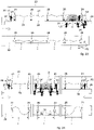
fig. 1 is a lateral schematic view of a first operating layout of a fire extinguisher plant according to the invention; -
fig. 2 is a lateral schematic view of a second operating layout of the present fire extinguisher plant; -
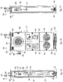
fig. 3 is a lateral view of a first embodiment of a primary fire extinguisher device connectable to a water supply network; -
fig. 4 is a front view of the primary fire extinguisher device infig. 3 ; -
fig. 5 is a second lateral view of the primary fire extinguisher device infig. 3 and fig. 4 ; -
fig. 6 is a back view of the primary fire extinguisher device infigs. 3, 4, and 5 ; -
fig. 7 is a longitudinal section view of the primary fire extinguisher device infigs. 3-6 ; -
fig. 8 is a front view of a second embodiment of the primary fire extinguisher device; -
fig. 9 is a longitudinal section view of the primary fire extinguisher device infig. 8 ; -
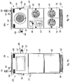
fig. 10 is a first lateral view of a first embodiment of a secondary fire extinguisher device; -
fig. 11 is a front view of the secondary fire extinguisher device infig. 10 ; -
fig. 12 is a second lateral view of the secondary fire extinguisher device infigs. 10 and 11 ; -
fig. 13 is a back view of the secondary fire extinguisher device infigs. 10, 11 and 12 ; -
fig. 14 is a front view of a second embodiment of the secondary fire extinguisher device; -
fig. 15 is a first lateral view of a third embodiment of the secondary fire extinguisher device; -
fig. 16 is a front view of the secondary fire extinguisher device infig. 15 ; -
fig. 17 is a second lateral view of the secondary fire extinguisher device infigs. 15 and 16 ; -
fig. 18 is a front view of the secondary fire extinguisher device infigs. 15, 16 and 17 ; -
fig. 19 is a front view of a fourth embodiment of the secondary fire extinguisher device; -
fig. 20 is a longitudinal section view of a variant of the primary fire extinguisher device; -
fig. 21 is a lateral schematic view of a third operating layout of a fire extinguisher plant according to the invention; -
fig. 22 is a lateral schematic view of a fourth operating layout of a fire extinguisher plant according to the invention; -
fig. 23 is a lateral schematic view of a fifth operating layout of a fire extinguisher plant according to the invention; -
fig. 24 is a lateral schematic view of a sixth operating layout of a fire extinguisher plant according to the invention. - To facilitate comprehension, the same reference numbers have been used, where possible, to identify identical common elements in the drawings. It is understood that elements and characteristics of one embodiment can conveniently be incorporated into other embodiments without further clarifications.
- We will now refer in detail to the various embodiments of the present invention, of which one or more examples are shown in the attached drawings. Each example is supplied by way of illustration of the invention and shall not be understood as a limitation thereof. For example, the characteristics shown or described insomuch as they are part of one embodiment can be adopted on, or in association with, other embodiments to produce another embodiment. It is understood that the present invention shall include all such modifications and variants.
- Before describing these embodiments, we must also clarify that the present description is not limited in its application to details of the construction and disposition of the components as described in the following description using the attached drawings. The present description can provide other embodiments and can be obtained or executed in various other ways. We must also clarify that the phraseology and terminology used here is for the purposes of description only, and cannot be considered as limitative.
- With reference to the attached drawings and in particular to
figs. 1, 2 ,21-24 , a fire-extinguisher orfire extinguisher plant 20, according to some embodiments of the invention, comprises at least one primaryfire extinguisher device 21 which can be installed on afloor 22 of a structure. - The
floor 22 can define, for example, a platform of a railway station. - The
fire extinguisher plant 20 can also comprise a plurality of secondary fire extinguisher devices 261-26z, selectively connected hydraulically to each other and to one or more primaryfire extinguisher devices 21 according to the methods described below. - According to possible solutions, the at least one primary
fire extinguisher device 21 and the secondary fire extinguisher devices 261-26z can be disposed in sequence along a predefined trajectory, or path. - By way of example only, it can be provided that the at least one primary
fire extinguisher device 21 and the secondary fire extinguisher devices 261-26z are reciprocally distanced from each other, at intervals of distances I along the trajectory or path. These ranges of distances I can be substantially all the same. - However, in variant embodiments, the intervals of distances I between secondary fire extinguisher devices 261-26z and/or between the primary
fire extinguisher device 21 and the first secondary fire extinguisher device 261-26z can vary according to different requirements, possible structural obstacles and the planimetric configuration of the infrastructure. - The trajectory or path can be provided with a
first end 27 and asecond end 28 which can be distinguished from one another, identifying an open path, or they can be coincident, identifying a closed path. - According to a possible solution, the trajectory or path has a length L (
figs. 1 and 2 ) and along the length L there is at least one primaryfire extinguisher device 21 and the secondaryfire extinguisher devices 26. - The trajectory or path can have a rectilinear configuration, bent in segments, curvilinear or mixed rectilinear and curvilinear depending on the particular embodiment of the structure in which the
fire extinguisher plant 20 according to the invention is installed. - The trajectory or path develops outside the
flooring 22 since, as described below, the present invention does not require invasive works on the latter, as instead is provided in known solutions. - According to a possible solution (
figs. 1 ,21 and23 ), the at least one primaryfire extinguisher device 21 can be installed in correspondence with thefirst end 27 of the trajectory or path, and the secondaryfire extinguisher devices 26 are located in subsequent sequence along the trajectory or path, for example from the first secondaryfire extinguisher device 261 to the last secondaryfire extinguisher devices 26z, located in succession between them starting from the primaryfire extinguisher device 21. - The last
secondary device 26z is instead located near thesecond end 28 opposite to that in which the primaryfire extinguisher device 21 is positioned. - According to a variant embodiment (
figs. 2 ,22 and24 ), thefire extinguisher plant 20 according to the invention can comprise at least two primaryfire extinguisher devices first end 27 and the other is provided in thesecond end 28. The secondary fire extinguisher devices 261-26z are connected to each of the primaryfire extinguisher devices - As an alternative to the above, it can be provided that a plurality of secondary
fire extinguisher devices 26 can be selectively connected to the same primaryfire extinguisher device 21, to define a network or grid of secondaryfire extinguisher devices 26 which branches off from the sole primaryfire extinguisher device 21 in a star configuration, that is, in different directions. In accordance with this solution, it can be provided that the primaryfire extinguisher device 21 is configured to rotate around its own axis of rotation to orient itself according to a plurality of stellar development trajectories, along which trajectories one or more secondaryfire extinguisher devices 26 are installed. - According to a possible solution (
figs. 3-9 and20 ), the primaryfire extinguisher device 21 comprises at least onecasing 29, defining at least one compartment to house its components. - The
casing 29 can comprise a base 30 configured to allow it to be attached to thefloor 22, for example by means of removable attachment elements such as bolts or suchlike. - The primary
fire extinguisher device 21 is connected to awater supply network 25 configured to supply the water. - According to some embodiments (
figs. 7, 9 and20 ), the primaryfire extinguisher device 21 is provided with atubular element 31 connected to thewater supply network 25, for example by connection means. - By way of example only, the connection means can comprise sleeves, shutters, valves, or suchlike. The
tubular element 31 is positioned at least partly in thecasing 29. - The
tubular element 31 is provided with interception means, such as aninterception valve 35 configured to selectively intercept the flow of water coming from thewater supply network 25. - The
interception valve 35 can be drivable manually as shown in the drawings, or it can be electrically driven, for example remotely, or with a suitable electric command line. - According to possible solutions (
figs. 7, 9 ,20 ), theinterception valve 35 can comprise alever 36, possibly installed at least partly protruding from thecasing 29 and selectively drivable to allow the passage of water from thewater supply network 25 to the primaryfire extinguisher device 21. - According to another embodiment of the invention, the
interception valve 35 can be driven, also in wireless mode, with abutton 37, or other command possibly installed in the secondary fire extinguisher devices 26 (seefigs. 10 and15 ) as better described hereafter in the description. - The
button 37 can be a lock-type button, that is, it can be activated with a suitable key available to specialized operators, encoded or suchlike. - For redundancy and safety requirements, it can be provided that the opening of the
interception valve 35 is conditioned by the activation of thebutton 37 and thelever 36. - According to a possible solution, the
tubular element 31 is connected, for example with aconnector 32, to at least one othertubular element 33, in this case twotubular elements 33, to each of which arespective hydrant 34 can be selectively connected, and can be used to deliver a jet of water in the event of fire. The twotubular elements 33 can be provided with aninterception device 33a, for example a shutter that can be selectively opened/closed to allow the passage of water. - Each
hydrant 34 can comprise a hose and possibly water delivery lances, associated with the hose, which are selectively connectable fluidically to thetubular elements 33. - In accordance with the embodiment in
fig. 8 , the primary fire extinguisher device comprises twohydrants 34, of the wall type, possiblyUNI 45. - In accordance with the embodiment in
fig. 11 , the primary fire extinguisher device comprises asingle hydrant 34, of the wall-mounted type, possiblyUNI 45. - The at least one
hydrant 34 is positioned in thecasing 29, for example in abox 39 of the latter. Thecasing 29 can be provided withdoors 70 that can be selectively opened/closed, to allow access inside thecasing 29. - The
casing 29 can also compriseother boxes 39 in which at least one of one ormore extinguishers 40, one or more hoses 41 (figs 7-9 ,20 ) are housed, the functions of which will be described hereafter. - In accordance with
fig. 7 , the primaryfire extinguisher device 21 comprises twoextinguishers 40. - In accordance with
figs. 8 and 9 , the primaryfire extinguisher device 21 comprises asingle fire extinguisher 40 and arelaunch hose 41. The relaunch hoses can have a diameter of 70mm. - The
casing 29 can be provided withcorresponding doors 42 for access to theother boxes 39. - According to another aspect of the invention, the primary
fire extinguisher device 21 is equipped with at least one flexible dry water-relaunch pipe 24, configured to be hydraulically connected to thewater supply network 25 through thetubular element 31. - Here and hereafter in the description, the term "water-relaunch pipe" means a flexible pipe suitable to connect, in a selective manner, two
fire extinguisher devices - Moreover, by the term "dry", referring to the water-relaunch pipe, we mean a condition in which the pipe, in its condition of non-use, does not contain water inside it, while in its condition of use, pressurized water is fed through it.
- According to a possible solution, the dry water-
relaunch pipe 24, in its condition of non-use, can be wound in coils, while in its condition of use, it is completely unrolled. - In accordance with a possible solution, at least in its condition of non-use, the dry water-
relaunch pipe 24 is housed in thecasing 29. - By way of example only, the
casing 29 is provided with acompartment 62 in which the dry water-relaunch pipe 24 is disposed. Thecompartment 62 can be selectively opened/closed by means of acorresponding door 63. - According to a possible solution, the
casing 29 can be provided with anaperture 52 through which at least one first end of the dry water-relaunch pipe 24 protrudes. - The dry water-
relaunch end 24 can be provided with aconnector 53 configured to allow its connection, for example, to one of the secondaryfire extinguisher devices 26, or, by means of possible reducers or distributors, to lances that deliver a jet of water, or respectively to other hoses to deliver the water jet. Theconnector 53 can be the rapid type, for example the Storz type. - In accordance with possible solutions, the
connector 53 can be selected from a group including a bayonet or threaded. According to one solution, theconnector 53 can be the female type. - According to a possible solution, the dry water-
relaunch pipe 24 can be connected to thetubular element 31 by at least onepipe 43. - The
pipe 43 can be connected hydraulically to one end of the water-relaunch pipe 24. - According to a possible solution, the primary
fire extinguisher device 21 can comprise a windingdevice 44 configured to wind the dry water-relaunch pipe 24 around it. - The winding
device 44 can comprise atoothed disc 45 associated with afeed pawl 46 configured to prevent and/or allow the controlled unwinding of the dry water-relaunch pipe 24 from the windingdevice 44. - The winding
device 44 can be associated with a clamp andrelease lever 47, possibly cooperating with thetoothed disc 45 and configured to selectively clamp the rotation of the windingdevice 44, thus preventing an involuntary unwinding of the dry water-relaunch pipe 24. Thelever 47 can be manually drivable. - According to a possible solution, the
lever 47 can be coupled with aninterception member 71, for example a tap, installed along thepipe 43 connecting thetubular element 31 to the dry water-relaunch pipe 24. - In the normal condition of non-use, the
lever 47 prevents the windingdevice 44 from unwinding the dry water-relaunch pipe 24, and keeps theinterception member 71 in a closed condition, preventing the passage of water. - By driving the
lever 47, for example by rotating it by 90°, it is possible to release the windingdevice 44 and, at the same time, to open theinterception member 71. - In accordance with possible variant embodiments, it can also be provided provide that the primary
fire extinguisher device 21 is provided with at least two dry water-relaunch pipes 24 each of which is wound on a respective windingdevice 44 as defined above. The ends of the dry water-relaunch pipe 24 provided with theconnector 53 can be located protruding from opposite ends of thecasing 29, and a first windingdevice 44 allows to unwind the dry water-relaunch pipe 24 in a clockwise direction while the other allows counter-clockwise unwinding. This solution can be used to connect the primaryfire extinguisher device 21 to two secondaryfire extinguisher devices 26 which are distanced from the primary one in different directions. - The water-
relaunch pipe 24 of the primaryfire extinguisher device 21, if necessary, is therefore unwound and used to hydraulically connect at least a first secondaryfire extinguisher devices 261 located in succession to the primaryfire extinguisher device 21. In this way the water supplied by thewater supply network 25 can be made to pass through the primaryfire extinguisher device 21, its water-relaunch pipe 24, and made available to the secondaryfire extinguisher devices 261. - In accordance with a possible variant embodiment of the present invention, shown with reference to
Figs. 4 and20 , it can be provided that at least one of either the primaryfire extinguisher device 21 or the secondaryfire extinguisher devices 26, in this case the primaryfire extinguisher device 21, is provided with connection means 72 selectively connectable, during use, to an auxiliary water supply source, such as a fire-fighting vehicle, a tanker, or suchlike. - According to a possible solution, the connection means 72 are hydraulically connected to the dry water-
relaunch pipe 24, 24' to allow to supply water to the latter. - In accordance with some solutions, the connection means 72 can be interposed along a connection pipe to the dry water-
relaunch pipe 24, 24'. - If the connection means 72 are associated with the primary
fire extinguisher device 21, it can be provided that the connection means 72 are connected along the extension of thetubular element 31 for connection to thewater supply network 25. - The connection means 72 can comprise a
tubular segment 73 which connects to thetubular element 31. - The connection means 72 can be installed directly upstream of the
interception valve 35. - The connection means 72 can be provided with an
interception member 77, for the selective opening/closing of the passage of water. - According to a possible solution, the connection means 72 can also comprise, integrated in or associated with them, a
flow interception member 74, for example a one-directional valve, an interception valve, or a multi-way valve, configured to allow the flow of water from the auxiliary water supply source only toward the respective dry water-relaunch pipe 24, 24', and not in the opposite direction, that is, toward thewater supply network 25 or another secondaryfire extinguisher device 26. - According to another variant embodiment, the primary
fire extinguisher device 21b (fig. 20 ) and/or possibly at least one of the secondaryfire extinguisher devices 26, can comprise water discharge means interposed along the pipe, for example thepipe 43, which feeds water toward the respective dry water-relaunch pipe 24. - The discharge means 75 allow to discharge any residual water present in the pipe following any fire extinguishing intervention.
- The discharge means 75 can comprise a tubular segment possibly governed by a corresponding opening and closing
tap 76. - In accordance with some embodiments, the discharge means 75 are located downstream of the
interception valve 35. - A presser device can be associated with the winding
device 44, such as awater scraper 48 configured to flatten the dry water-relaunch pipe 24 as it is wound around the windingdevice 44 and to eliminate possible residual water present in the pipe itself. - During the winding operation, it can be provided to open the discharge means 75 to allow the discharge of the water and to prevent the latter from preventing the rewinding of the dry water-
relaunch pipe 24. - The presser device, or water scraper, can comprise a pair of
opposite rollers 49 between which the dry water-relaunch pipe 24 is made to pass, during use. - The
rollers 49 can be associated withelastic elements 50 configured to press therollers 49 against each other so as to flatten the dry water-relaunch pipe 24. - During the delivery of water through the dry water-
relaunch pipe 24, the water pressure exceeds the force of theelastic elements 50, allowing the water to pass. - In accordance with possible solutions, the secondary
fire extinguisher device 26, similar to the primaryfire extinguisher device 21, can also comprise a casing 29' (figs. 10-19 ) defining at least one compartment to house the respective operating components. - The secondary
fire extinguisher device 26 can simply be fixed to thefloor 22, by means of bolts or suchlike. - The secondary
fire extinguisher device 26 can be substantially the same as the primaryfire extinguisher device 21 described above, except that the secondaryfire extinguisher device 26 is not connected to thewater supply network 25. - According to another aspect of the present invention, the at least one secondary
fire extinguisher device 26 also comprises a dry water-relaunch pipe 24' substantially similar to the dry water-relaunch pipe described above with reference to the primaryfire extinguisher device 21. - The dry water-relaunch pipe 24' of the secondary
fire extinguisher device 26 can be selectively connected to the dry water-relaunch pipe 24 of another secondaryfire extinguisher device 262. - As shown hereafter, in a possible operating mode of the present
fire extinguisher plant 20, the dry water-relaunch pipes 24' of the secondaryfire extinguisher device 26 are unwound and connected together until they reach the secondaryfire extinguisher device 26 nearest a zone Z where there is a fire or the start of a fire, for example the secondaryfire extinguisher device 263 infig. 1 . - The dry water-relaunch pipe 24' of the secondary
fire extinguisher device 26 is installed inside the casing 29' of the latter. - Possibly, if the distance between the fire extinguisher devices is too great, it is possible to connect to the ends of the dry water-
relaunch pipes 24, 24' thehoses 41 which are possibly housed inside the respective fire extinguisher devices, whether they are primary or secondary. - The secondary
fire extinguisher device 26 can be provided with a windingdevice 44 substantially similar to that described above with reference to the primaryfire extinguisher device 21. - According to a possible solution, the secondary
fire extinguisher device 26 can be provided with a presser device, such as awater scraper 48, substantially similar to the one described above with reference to the primaryfire extinguisher device 21. - According to another aspect of the present invention, the one or more secondary
fire extinguisher devices hydrant 34, for example, similar to the one described above with reference to the primaryfire extinguisher device 21, and configured to deliver a jet of water during use. - In particular, each
hydrant 34 can be selectively connected to the secondaryfire extinguisher devices fire extinguisher device 21. - According to a possible solution, each secondary
fire extinguisher device 26a can be provided with aconnector 66 to which one of either the dry water-relaunch pipe 24 of the primaryfire extinguisher device 21 or the dry water-relaunch pipe 24 of another secondaryfire extinguisher device 26 is selectively connectable. - The
connector 66 can comprise connection elements such as bayonet type or threaded. - According to a possible solution, the
connector 66 can be the male type, to engage with thefemale connector 53 of therelaunch pipe 24. - According to a possible solution, the secondary
fire extinguisher device 26a comprises atubular element 67 provided with an opening and closingvalve 68 with which theconnector 66 is associated. - The
tubular element 67 is hydraulically connected to the dry water-relaunch pipe 24' and to the at least onehydrant 34 provided in the respective secondaryfire extinguisher device 26. - In accordance with this solution, it can be provided that the secondary
fire extinguisher device 26a does not need the discharge means 75 to discharge the water contained in the secondary fire extinguisher device and which would prevent the re-winding of the dry water-relaunch pipes 24. In particular, when rewinding of the latter is required, it is sufficient to open thevalve 68 associated with theconnector 66 in order to drain the water. - According to possible solutions, not shown, the
connector 66 can be connected to a remote controlled interception valve, located in the secondary fire extinguisher device 261-z and suitable to send the water toward the dry water-relaunch pipe 24' or toward thehydrants 34, through an appropriate connection. - According to possible solutions, the casing 29' can also be provided with an
aperture 52 through which at least oneend 53 of the respective dry water-relaunch pipe 24' is positioned protruding toward the outside. - According to a possible solution, the casing 29' of the secondary
fire extinguisher device 26a can be the "single" type (figs. 10-14 ), that is, it comprises a housing compartment for ahydrant 34, closed by a correspondingdoor 70, and a housing compartment for afire extinguisher 40, also closed by a correspondingdoor 42. - The
casing 29 of the primaryfire extinguisher device fire extinguisher plant 20a infig. 2 , which provides at each of the two ends 27 and 28 two primaryfire extinguisher devices - According to a variant embodiment (
figs. 15-19 ), the casing 29' can be the "double" type, that is, suitable to house twoadjacent hydrants 34 and two adjacent fire extinguishers 40 (fig. 16 ), or ahose 41 and a fire extinguisher 40 (fig. 19 ). - More specifically, the secondary
fire extinguisher device 26b infig. 14 substantially comprises the same elements as the secondaryfire extinguisher device 26a infig. 11 , with the exception that the single-type casing 29' comprises ahydrant 34 and ahose 41 withcorresponding access doors 70. Thehose 41 can have a diameter of 70mm. - The secondary
fire extinguisher device 26 infigs. 15, 16, 17 and18 substantially comprises the same elements as the previous secondaryfire extinguisher devices adjacent hydrants 34 and twoadjacent extinguishers 40 can be housed. - The secondary
fire extinguisher device 26c infig. 19 substantially comprises the same elements as the previous secondaryfire extinguisher device 26, wherein twoadjacent hydrants 34 and anadjacent fire extinguisher 40 andhose 41 can be housed in the double-type casing 29, as provided for the primaryfire extinguisher device 21a. - According to possible solutions, it can be provided that if the primary
fire extinguisher device 21 and the secondary fire extinguisher devices 261-26z are provided with thehose 41, the latter can be used as an extension for the dry water-relaunch pipe 24, 24'. - In this way, it is possible to halve the number of secondary fire extinguisher devices, while ensuring coverage of the zone comprised between two consecutive secondary fire extinguisher devices 261-26z, or between the primary fire extinguisher device and the first secondary fire extinguisher device 261-26z.
- From an operating point of view, in this case, the operator extracts the
hose 41 from the box and can carry it with him, for example under the shoulder or attached to his belt; the operator then unwinds the dry water-relaunch pipe 24' from the windingdevice 44 of a primary or secondary fire extinguisher device and connects the latter with the hose. Once the connection between the dry relaunch pipe and the hose has been made, the operator moves to the next secondary fire extinguisher device and can repeat the operations described above. - This allows to modulate, with intervals of distances I that vary according to needs, the number, disposition and use of the secondary fire extinguisher devices as a function of the different needs and requirements.
- With regard to rail traffic, in some smaller stations, it can be provided, where necessary, to install primary or secondary fire extinguisher devices with an interaxis equal to 50 meters, inserting into each of these an
extension hose 41 of the dry water-relaunch pipe 24, 24'. - The
casing 29 or 29' of the primaryfire extinguisher device 21 or secondaryfire extinguisher device 26 can also compriseportions 60 at the front, where decals, indications of use, writings or other can be put. - In these
areas 60, moreover, LED panels or strips with variable messages can be provided, for advertising reasons or for warnings to users, with the time and room temperature. - At least one of either the primary
fire extinguisher device 21 or the secondaryfire extinguisher device 26 can also comprise amonitor 61 to display data, messages, warnings or other. - The primary
fire extinguisher device 21 is also provided with at least one emergencyacoustic indicator 69 configured to emit an alarm signal, which can be designed for use in an automatic, semi-automatic or manual mode. Theacoustic indicator 69 can also be used to reproduce pre-recorded or non-pre-recorded messages of alarms and behavioral rules for users. - At least one of either the primary
fire extinguisher device 21 or the secondaryfire extinguisher device 26 can also comprise a fire-alarm device 55, for example of an audiovisual type or suchlike. - According to possible solutions (
figs. 3-9 and20 ), at least one of either the primaryfire extinguisher device 21 or the secondaryfire extinguisher device 26 can comprise avent valve 54 configured to allow to vent the air present in the devices and which is discharged when pressurized water is introduced into the respective fire extinguisher device. - The
vent valve 54 can be installed on thecasing 29 or 29', for example on its top and connected to the water supply pipe to the dry water-relaunch pipes. - In accordance with a possible solution, for example in the case of application in railway stations, subways, or suchlike, the infrastructure in which the plant in accordance with the present invention is installed is provided with at least one
electric traction line 23, that is, an electric supply line for the means of transport of a train, a subway, or suchlike. According to these embodiments, at least one of either the primaryfire extinguisher device 21 or the secondaryfire extinguisher device 26 is provided with earthingdevices 56, also known in this field as insulatingsticks 56, which can be selectively connected to theelectric traction line 23 so that they can carry them to a safe condition (figs. 3 ,10 , and15 ). - The earthing
devices 56 can be housed on one side of thecasing 29, 29' and are selectively removable from it when needed. - The earthing
devices 56 can comprise a plurality oftubular elements 57, telescopic and removable, ahook 59 which can be positioned during use in contact with theelectric traction line 23 and agrip 58 for a user. - In particular, it is possible to provide that the earthing
devices 56 are installed at intervals of at least five secondaryfire extinguisher devices 26a. - The primary or secondary fire extinguisher devices, or at least some of them, can also be provided with hooks or devices to extinguish smoldering fires, or perforating water lances 79 or suchlike which have a perforating terminal part and from which water can be supplied.
- The perforating water lances 79 can be installed on the side of at least one of the primary or secondary fire extinguisher devices.
- Such devices can be used, for example, to perforate the plates and insulation of railway carriages, and to spray the inaccessible environment in which the "smothered" fire has developed.
- If necessary, the primary or secondary fire extinguisher devices can be equipped, at predefined intervals, with fire blankets, fire protection masks, thermal blankets to cover burned persons, tanks of foaming liquid with water-foam premixers and anything else deemed useful for rescue purposes.
- All the secondary
fire extinguisher devices 26 are provided, for example on the left side with respect to the central elevation, with twooptical indicators - The
optical indicators button 37 by the operator who is near the secondaryfire extinguisher device 26 closest to the fire, to indicate to the operator who is near the primaryfire extinguisher device 21 that it is possible to supply the entire network of the trajectory hydraulically by opening theinterception valve 35. - The
optical indicators fire extinguisher device fig. 3 . - In particular, the proposed fire extinguisher system provides that the
optical indicators button 37 with which each secondary fire extinguisher device is equipped before theinterception valve 35 is opened. - The
button 37 can be activated by means of a security key, or by a remote electric pulse, coming from a "control room" or directly by thebutton 37, or manually by means of the shutter or by both devices for reasons of redundancy. - The pressure exerted by the fire extinguisher operator on the
button 37 not only changes theoptical indicators fire alarm devices 55, and theacoustic indicators 69 that warn the people present on the platform of the existence of an emergency in progress. - In the case of the
fire extinguisher plant 20 infig. 1 , an intervention method following a fire or beginning of a fire in zone Z can be carried out as described below. - An operator U1 moves into correspondence with the first
fire extinguisher device 21 and by driving thelever 47, for example by rotating it by 90°, releases the windingdevice 44 and allows to unroll thepipe 24 as far as thesecondary device 261. - The
lever 47, when driven, therefore performs the following functions: - it allows to unroll the
pipe 24 with theconnector 53; - it allows to fill the
pipe 24 of the primaryfire extinguisher device interception member 71. - The operator U1 connects the
connector 53 of therelaunch pipe 24 to theconnector 66 present in the secondaryfire extinguisher device 261. - Then the operator releases the winding
device 44 of the secondaryfire extinguisher device 261, by means of the correspondinglever 47, so that the corresponding dry water-relaunch pipe 24' can extend from the secondaryfire extinguisher device 261 to the secondaryfire extinguisher device 262. - The operation is repeated to connect the relaunch pipe 24' of the secondary
fire extinguisher device 262 to the secondaryfire extinguisher device 263, which is assumed to be near the fire zone Z. - Each time the
connector 53 of thepipe 24, 24' is connected to theconnector 66 of the subsequent secondaryfire extinguisher device 26, thevalve 68 is also opened. - In the case of the last secondary
fire extinguisher device 263, from which water must be supplied with thecorresponding hydrants 34, the opening of thevalve 68 allows the water to flow directly to thehydrants 34, located for example at the bottom of thecasing 29, without flowing into the pipe 24' of the secondaryfire extinguisher device 263, since the interception valve connected to the pipe 24' is closed. - Another operator U2, possibly with the help of other operators, using the insulating
stick 56, quickly earths theelectric traction line 23, placing thehook 59 on theelectric traction line 23. - Once the earthing operation is completed and therefore the
fire extinguisher plant 20a has been made safe, the operator U2 sends a consent to the operator U1 stationed near the last secondaryfire extinguisher device 263. - At this point, the operator U1 can activate the
button 37 of the secondaryfire extinguisher device 263 which can act directly on theinterception valve 35 of the primaryfire extinguisher device 21 or can act on theoptical indicators interception valve 35. At the same time the activation of anybutton 37 located on each secondaryfire extinguisher device 26 also activates thefire alarm devices 55 andacoustic indicators 69. - The water coming from the
water supply network 25 can then enter the primaryfire extinguisher device 21 and reach up to the dry water-relaunch pipe 24. Advantageously, therefore, only once the supply of water to thefire extinguisher plant 20 by means of thebutton 37 has been enabled can thepipe 24 of the primaryfire extinguisher device 21 also deliver water to the pipes 24' of the secondaryfire extinguisher devices 26, starting from the primaryfire extinguisher device 21 and up to the hydrant orhydrants 34 of one or more secondaryfire extinguisher devices 26 closest to the fire zone Z. - The entire water network obtained is pressurized at the designed working pressure, the filling of the
pipe 24 moves the roller bars 49 away, thefire alarm device 55 starts operating, and in short the twohydrants 34 of the secondaryfire extinguisher device 263 are fed, or the single hydrant in the case of a secondaryfire extinguisher device 26 with a single-type casing 29'. - The
optical indicators acoustic indicator 69 for emergency signaling to the users is enabled to be used in automatic, semi-automatic or manual mode. - The operator U2 reaches the operator U1 and both can use the
hydrants 34 of the secondaryfire extinguisher device 263 to initiate fighting the fire in zone Z. - It should be noted that, until the operator U1 presses the
button 37 to consent to the opening of theinterception valve 35 of the primaryfire extinguisher device 21, the whole fire-extinguisher plant 20, including the primaryfire extinguisher device 21 and subsequent secondaryfire extinguisher devices - The connection between the primary
fire extinguisher device 21a and the various secondaryfire extinguisher devices various relaunch pipes 24 and 24', therefore above ground, that is, outside thefloor 22. - It should be emphasized that, naturally, if the operating requirements so require, the
hydrants 34 of two or more secondary fire extinguisher devices subsequent to the area affected by the fire can also be used. - In addition, a
hose 41, forexample UNI 45, once entirely unrolled, can be connected directly to theconnector 53 of thelast relaunch pipe 24, if one-directional, or to the connectors of thelast relaunch pipes 24, if two-directional. Thehoses 41 can be doubled if a line splitter with two connectors is mounted on theconnector 53. - In the case of a
fire extinguisher plant 20a of the type shown infig. 2 , the above operations are repeated, coming from two opposite sides of the fire zone Z. - In this case, four operators U1, U2, U3 and U4 can be involved, who will be able to use four
hydrants 34 or more fire extinguisher services as described above. - Further functioning diagrams of fire extinguisher plants 20 or 20a with single or double feed are shown in
figs. 21 to 24 . - In specific cases, in
fig. 21 the fire extinguisher plant is the one-directional network type and is provided with two wall hydrants for eachfire extinguisher device fig. 22 the fire extinguisher plant is the two-directional network type with two wall hydrants for eachfire extinguisher device fig. 23 the fire extinguisher plant is the one-directional network type and is provided with a wall hydrant for eachfire extinguisher device fig. 24 the fire extinguisher plant is the two-directional network type with a wall hydrant for each fire extinguisher device with the possibility that two, four or even six operators use water lances simultaneously. - Considering for example the cases in
fig. 21 andfig. 23 , that is, of a single-feedfire extinguisher plant 20, similarly to the case infig. 1 , the primaryfire extinguisher device 21b is placed in the first position on thefloor 22, and the secondaryfire extinguisher devices 26 follow, for example with an interaxis I of 25, 30 or 40 meters. - In the event of a fire in correspondence with zone Z, the operator U2 carries out the following operations:
- 1. He moves in correspondence with the first primary
fire extinguisher device 21b and, by rotating thelever 47 clockwise, for example by 90°, he releases the windingdevice 44; at the same time, by carrying out this maneuver, theinterception member 71 is opened; - 2. He unwinds the
pipe 24 until it reaches the next secondaryfire extinguisher device 26; - 3. He connects the
female connector 53 to themale connector 66, fixed on the side of the secondaryfire extinguisher device 26, and opens thevalve 68 located upstream, rotating the corresponding lever for example by 90°. - From the first primary
fire extinguisher device 21b and following, up to the penultimate secondaryfire extinguisher device 26 of those needed to be activated in order to reach zone Z, the operator U2 performs the operations 1, 2, 3 listed above. When the secondaryfire extinguisher device 26 nearest the intervention zone Z has been reached, he only performs operation 3 and waits for the operator U1, or another qualified operator, with one of the insulatingsticks 56, made available in the primary fire extinguisher devices and possibly in the secondary fire extinguisher devices, to carry out the maneuver to earth theelectric traction line 23. - After completing this last operation to make the railway system safe for the purposes of using water to fight the fire, and having obtained the necessary consent, the operator U2 activates the
button 37, which can be commanded, for example, by the release key. The operator U2 with thebutton 37 can change theoptical indicators interception valve 35. Theinterception valve 35 can be opened manually using thelever 36 to supply the entire fire extinguisher line as far as the last secondaryfire extinguisher device 26 activated, or by means of thebutton 37 which sends an electric pulse to the electro valve of the interception valve. - The entire water network is pressurized in a time of less than sixty seconds as laid down by the legislation in this field, at the designed working pressure and with hydraulic performances such as to always ensure simultaneous use by the fire brigade or by the station fire-fighting operators, of not less than 3
UNI 45 hydrants located in the most unfavorable hydraulic position, with a minimum flow rate for each hydrant of, for example, 120 liters/min and a residual pressure to the farthest hydrant of not less than 0.2 MPa. The filling of the dry water-relaunch pipes 24, 24' lifts the spring-type water scrapers 48, thefire alarm devices 55 come into operation, thehydrants 34 are fed and theoptical indicators acoustic indicator 69 to signal an emergency to the users is enabled so that it can be used in automatic, semi-automatic or manual mode. - The
fire alarm devices 55, theoptical indicators acoustic indicator 69 and thebuttons 37 can be electrically powered, according to the characteristics of the site where the invention is installed. By way of example only, these components can be electrically connected with electrical conductors powered with a 12 Volt or 24 Volt voltage, or by low voltage buffer batteries incorporated on eachfire extinguisher device - The operator U1 joins the operator U2 and both unwind the hoses of the
hydrants 34 of the secondaryfire extinguisher device 26, to initiate fighting the fire with a total water output of, for example, 240 liters/min or 480 liters/min if assisted by two other fire-fighting operators (fig. 21 ) or 240 liters/min in the case of asingle hydrant 34 for each fire extinguisher device. - If the surrounding conditions, with regard to the mass of the fire, require that a greater quantity of fire extinguisher water is needed, the water-relaunch pipe of the last secondary
fire extinguisher device 26 can also be completely unwound and connected to the end of the latter, by means of an appropriate adapter, ahose 41 with a water delivery lance (120 mm outlet), or even, by means of an appropriate adapter, a two-way line splitter to supply twoother hoses 41 with fire extinguisher water delivery nozzles (120 mm outlet) as shown infig. 21 (a maximum of six operators with a total capacity of 720 liters/min), infig. 22 (a maximum of eight operators with a total capacity of 960 liters/min), infig. 23 (a maximum of four operators with a total capacity of 480 liters/min) and infig. 24 (a maximum of six operators with a total capacity of 720 liters/min). - With reference to
figs. 22 or24 , the operators U2 and U4 perform the functions previously described and then with the help of the operator U1 and of a possible other operator U3 they begin the activity of fighting the fire by using two, three or fourhydrants 34 according to needs. - By using, by means of a suitable adapter, a two-way line splitter connected to the terminals of the
relaunch pipes 24, it is possible to have eight hydrants (fig. 22 ) or six hydrants 34 (fig. 24 ). - The fire extinguisher plants 20 and/or 20a can be connected to a central unit to control, manage and command operations, from which, for example, the consent signals to begin the firefighting operations can be verified and displayed.
- We wish to emphasize again that the present
fire extinguisher plant - The present fire extinguisher plant also brings the following advantages: it eliminates the costs for the construction of the underground laying of the water supply pipe; the fire extinguisher devices (built in external workshops) can be installed in a short time and without any interference on public transport; it does not interfere with other networks, buried or not, of plants serving the station; it overcomes any historical-architectural constraints that can be imposed by the relative state Authorities in order not to spoil the flooring if of historical value; the production costs of the plant can be quickly amortized by resorting to the sale or rental of advertising spaces.
- It is clear that modifications and/or additions of parts may be made to the water-fed fire extinguisher plant, with a dry, multiple development network, outside the ground as described heretofore, without departing from the field and scope of the present invention.
- It is also clear that, although the present invention has been described with reference to some specific examples, a person of skill in the art shall certainly be able to achieve many other equivalent forms of water-fed fire extinguisher plant, with a dry, multiple development network, outside the ground, having the characteristics as set forth in the claims and hence all coming within the field of protection defined thereby.
- In the following claims, the sole purpose of the references in brackets is to facilitate reading: they must not be considered as restrictive factors with regard to the field of protection claimed in the specific claims.
Claims (17)
- Fire extinguisher plant, in particular with a dry, multiple development network, outside the ground and fed by water, particularly suitable for installation on floors (22) of large structures such as airports, train stations, marine terminals and subway stations, either wholly or partly underground, or other, wherein it comprises at least a primary fire extinguisher device (21, 21a, 21b) suitable to be connected to a water supply network (25) and provided with at least a water-relaunch pipe (24), and one or more secondary fire extinguisher devices (26, 26a, 26b, 26c) each provided with at least one hydrant (34) to supply a flow of water, and at least a dry water-relaunch pipe (24') for connection to another of said secondary fire extinguisher devices (26, 26a, 26b, 26c), and in that said secondary fire extinguisher devices (26, 26a, 26b, 26c) are able to be connected at least in sequence starting from said primary fire extinguisher device (21, 21a) by means of said relaunch pipes (24, 24'), said pipe (24) of said primary fire extinguisher device (21, 21a) being configured to deliver water to the pipes (24') of the secondary fire extinguisher devices (26, 26a, 26b, 26c) starting from said primary fire extinguisher device (21, 21a) and as far as the hydrant (34') of at least one secondary fire extinguisher device (26, 26a, 26b, 26c) nearest to a fire zone (Z).
- Fire extinguisher plant as in claim 1, characterized in that the at least one primary fire extinguisher device (21) and the secondary fire extinguisher devices (26, 26a, 26b, 26c) are disposed in sequence along a predefined trajectory or path, in that the at least one primary fire extinguisher device (21) is installed in correspondence with a first end (27) of said trajectory or path, and in that the secondary fire extinguisher devices (26, 26a, 26b, 26c) are located in sequence along said trajectory, and the last secondary device (26) of the sequence is located in proximity to a second end (28), opposite the first end (27).
- Fire extinguisher plant as in claim 1, characterized in that it comprises at least two primary fire extinguisher devices (21), one of which is provided in correspondence with a first end (27) and the other is provided in a second end (28) of a positioning trajectory of said secondary fire extinguisher devices (26, 26a, 26b, 26c), and in that respective secondary fire extinguisher devices (26, 26a, 26b, 26c) can be connected to each of said primary fire extinguisher devices (21), to define two sequences of secondary fire extinguisher devices (26, 26a, 26b, 26c).
- Fire extinguisher plant as in claim 1, characterized in that a plurality of fire extinguisher devices (26) are able to be selectively connected to the at least one primary fire extinguisher device (21), in order to define a network or grid of secondary fire extinguishers (26) that branch off from the single primary fire extinguisher device (21) in different directions.
- Fire extinguisher plant as in any claim hereinbefore, characterized in that said primary fire extinguisher device (21, 21a, 21b) is provided with one or more hydrants (34) for the direct delivery of water and with an interception valve (35) suitable to allow the direct feed toward said hydrants (34) or to send water to the relaunch pipe (24).
- Fire extinguisher plant as in claim 5, characterized in that said interception valve (35) of the primary fire extinguisher device (21, 21a, 21b) is driven remotely by means of a command (37) disposed on said secondary fire extinguisher devices (26, 26a, 26b, 26c).
- Fire extinguisher plant as in claims 5 and 6, characterized in that said interception valve (35) can be manually driven using a lever (36).
- Fire extinguisher plant as in any claim hereinbefore, characterized in that the dry water-relaunch pipes (24, 24') of the primary and secondary fire extinguisher devices (21, 21a, 21b, 26, 26a, 26b, 26c) comprise a connector (53) suitable to be connected to a connector (66) provided in the secondary fire extinguisher devices (26, 26a, 26b, 26c).
- Fire extinguisher plant as in any claim hereinbefore, characterized in that at least one of either the primary fire extinguisher device (21) or the secondary fire extinguisher device (26) is provided with connection means (72) which can be selectively connected, during use, to an auxiliary water source.
- Fire extinguisher plant as in claim 9, characterized in that said connection means (72) are interposed along a connection pipe to said dry water-relaunch pipe (24, 24') of the primary (21) and/or secondary (26) fire extinguisher device.
- Fire extinguisher plant as in claim 9 or 10, characterized in that said connection means (72) are provided with an interception member (77) for the selective opening/closing of the water passage.
- Fire extinguisher plant as in any of the claims from 9 to 11, characterized in that said connection means (72) comprise a flow interception member (74) configured to allow the flow of water from the auxiliary water source only toward the respective dry water-relaunch pipe (24, 24').
- Fire extinguisher plant as in any claim hereinbefore, characterized in that the primary fire extinguisher device (21b) and/or at least one of the secondary fire extinguisher devices (26) comprises water discharge means (75) interposed along the pipe which feeds the water toward the respective dry water-relaunch pipe (24).
- Fire extinguisher plant as in any claim hereinbefore, characterized in that said primary fire extinguisher device (21, 21a, 21b) and said secondary fire extinguisher device (26, 26a, 26b, 26c) comprise at least one casing (29, 29') in which the respective dry water-relaunch pipe (24) is housed.
- Fire extinguisher plant as in any claim hereinbefore, characterized in that at least one of either said primary fire extinguisher device (21, 21a, 21b) or said secondary fire extinguisher device (26, 26a, 26b, 26c) comprise a perforation water launch (79) provided with a perforating end configure to deliver water.
- Fire extinguisher method using a fire extinguisher plant as in any of the claims from 1 to 15, characterized in that it comprises: the connection of at least one primary fire extinguisher device (21, 21a, 21b) to a water supply network (25) and provided with at least one water-relaunch pipe (24); the connection at least in sequence starting from said primary fire extinguisher device (21, 21a, 21b) of one or more secondary fire extinguisher devices (26, 26a, 26b, 26c) provided with corresponding dry water-relaunch pipes (24'), said secondary fire extinguisher devices (26, 26a, 26b, 26c) each being provided with one or more hydrants (34) able to be connected at least to a previous relaunch pipe (24, 24') of the sequence; the delivery of water from said dry water-relaunch pipe (24) of said primary fire extinguisher device (21, 21a, 21b) to the dry water-relaunch pipes (24') of the secondary fire extinguisher devices (26, 26a, 26b, 26c) as far as the hydrant or hydrants (34, 34') of at least one secondary fire extinguisher device (26, 26a, 26b, 26c) nearest a fire zone (Z) or start of a fire.
- Method as in claim 16, characterized in that the water delivery step from said secondary fire extinguisher device (26, 26a, 26b, 26c) nearest the fire zone (Z) takes place following at least a signal of consent sent by said secondary fire extinguisher device (26, 26a, 26b, 26c) nearest the fire zone (Z) toward said primary fire extinguisher device (21, 21a, 21b).
Priority Applications (2)
| Application Number | Priority Date | Filing Date | Title |
|---|---|---|---|
| RS20220636A RS63374B1 (en) | 2017-12-20 | 2018-12-19 | FIRE EXTINGUISHING PLANT USING WATER |
| SI201830709T SI3727608T1 (en) | 2017-12-20 | 2018-12-19 | Fire extinguisher plant using water |
Applications Claiming Priority (3)
| Application Number | Priority Date | Filing Date | Title |
|---|---|---|---|
| IT201700147695 | 2017-12-20 | ||
| IT201800008003 | 2018-08-09 | ||
| PCT/IT2018/050251 WO2019123502A1 (en) | 2017-12-20 | 2018-12-19 | Fire extinguisher plant using water |
Publications (2)
| Publication Number | Publication Date |
|---|---|
| EP3727608A1 EP3727608A1 (en) | 2020-10-28 |
| EP3727608B1 true EP3727608B1 (en) | 2022-04-06 |
Family
ID=65033637
Family Applications (1)
| Application Number | Title | Priority Date | Filing Date |
|---|---|---|---|
| EP18836418.6A Active EP3727608B1 (en) | 2017-12-20 | 2018-12-19 | Fire extinguisher plant using water |
Country Status (5)
| Country | Link |
|---|---|
| EP (1) | EP3727608B1 (en) |
| ES (1) | ES2921904T3 (en) |
| RS (1) | RS63374B1 (en) |
| SI (1) | SI3727608T1 (en) |
| WO (1) | WO2019123502A1 (en) |
Families Citing this family (2)
| Publication number | Priority date | Publication date | Assignee | Title |
|---|---|---|---|---|
| CN112206457B (en) * | 2020-10-20 | 2022-09-09 | 武汉理工大学 | A kind of biomass gel-based dry water powder fire extinguishing agent and preparation method thereof |
| JP7592529B2 (en) * | 2021-03-24 | 2024-12-02 | ホーチキ株式会社 | Electrical panel, disaster prevention equipment storage device, and disaster prevention equipment |
Family Cites Families (2)
| Publication number | Priority date | Publication date | Assignee | Title |
|---|---|---|---|---|
| US2274784A (en) * | 1939-12-28 | 1942-03-03 | Cardox Corp | Fire protection system for large airports |
| FR3008893B1 (en) * | 2013-07-24 | 2017-09-01 | Tunzini Prot Incendie | FIRE FIGHTING DEVICE |
-
2018
- 2018-12-19 WO PCT/IT2018/050251 patent/WO2019123502A1/en not_active Ceased
- 2018-12-19 RS RS20220636A patent/RS63374B1/en unknown
- 2018-12-19 ES ES18836418T patent/ES2921904T3/en active Active
- 2018-12-19 EP EP18836418.6A patent/EP3727608B1/en active Active
- 2018-12-19 SI SI201830709T patent/SI3727608T1/en unknown
Also Published As
| Publication number | Publication date |
|---|---|
| WO2019123502A1 (en) | 2019-06-27 |
| EP3727608A1 (en) | 2020-10-28 |
| SI3727608T1 (en) | 2022-11-30 |
| RS63374B1 (en) | 2022-08-31 |
| ES2921904T3 (en) | 2022-09-02 |
Similar Documents
| Publication | Publication Date | Title |
|---|---|---|
| US9764174B2 (en) | Rain maker wildfire protection and containment system | |
| US20160051850A1 (en) | Fire Protection System | |
| KR101037256B1 (en) | Disaster prevention device inside the tunnel | |
| ES2272276T3 (en) | TELESCOPIC ROBOT AGAINST FIRE OR MANUAL OR REMOTE CONTROL THAT CAN BE AUTOMATICALLY CONNECTED TO WATER DRIVES AND MOUNTED SUSPENDED FROM A MONORAIL OF A TUNNEL. | |
| KR100981287B1 (en) | Forest fire of extinguisher | |
| EP3727608A1 (en) | Fire extinguisher plant using water | |
| CN105727473A (en) | Plane domain guide rail type high-rise building fire rescue equipment | |
| EP2032215B1 (en) | Railway or urban subway's route tunnel with a rail in combination with a fire extinguishing device of deluge type | |
| KR101331616B1 (en) | Ground water layer tower for forest fire prenention | |
| RU2722615C1 (en) | Fire-fighting pumping-hose system | |
| CN213527221U (en) | Fire-fighting system for multi-stage linkage fire extinguishing of temporary storage pit for hazardous wastes | |
| JP4623551B2 (en) | Fire hydrant equipment | |
| JP2008104977A (en) | Simple sprinkler | |
| KR102718955B1 (en) | Fire hydrant box for emergency | |
| KR200400410Y1 (en) | Water Pumping Apparatus for Extinguishing Forest Fire | |
| CN202942577U (en) | GPS (Global Position System) intelligent automatic sprinkler fire extinguishing device | |
| JP2010188151A (en) | Hydrant apparatus | |
| CN108744374A (en) | A kind of building and its fire extinguishing system and fire-fighting mode | |
| KR101178498B1 (en) | Fire extiguisher using wireless remot control | |
| JP2022118250A (en) | Fire hydrant device | |
| KR200324165Y1 (en) | Fire extinguisher for fire fighting education | |
| CN218485051U (en) | Row-connected hangar | |
| CN112843571A (en) | Automatic tunnel spraying fire extinguishing system and fire extinguishing method | |
| CN214596959U (en) | Tunnel automatic spray fire extinguishing system | |
| JP2002172182A (en) | Building disaster prevention system |
Legal Events
| Date | Code | Title | Description |
|---|---|---|---|
| STAA | Information on the status of an ep patent application or granted ep patent |
Free format text: STATUS: UNKNOWN |
|
| STAA | Information on the status of an ep patent application or granted ep patent |
Free format text: STATUS: THE INTERNATIONAL PUBLICATION HAS BEEN MADE |
|
| PUAI | Public reference made under article 153(3) epc to a published international application that has entered the european phase |
Free format text: ORIGINAL CODE: 0009012 |
|
| STAA | Information on the status of an ep patent application or granted ep patent |
Free format text: STATUS: REQUEST FOR EXAMINATION WAS MADE |
|
| 17P | Request for examination filed |
Effective date: 20200716 |
|
| AK | Designated contracting states |
Kind code of ref document: A1 Designated state(s): AL AT BE BG CH CY CZ DE DK EE ES FI FR GB GR HR HU IE IS IT LI LT LU LV MC MK MT NL NO PL PT RO RS SE SI SK SM TR |
|
| AX | Request for extension of the european patent |
Extension state: BA ME |
|
| DAV | Request for validation of the european patent (deleted) | ||
| DAX | Request for extension of the european patent (deleted) | ||
| GRAP | Despatch of communication of intention to grant a patent |
Free format text: ORIGINAL CODE: EPIDOSNIGR1 |
|
| STAA | Information on the status of an ep patent application or granted ep patent |
Free format text: STATUS: GRANT OF PATENT IS INTENDED |
|
| INTG | Intention to grant announced |
Effective date: 20211109 |
|
| GRAS | Grant fee paid |
Free format text: ORIGINAL CODE: EPIDOSNIGR3 |
|
| GRAA | (expected) grant |
Free format text: ORIGINAL CODE: 0009210 |
|
| STAA | Information on the status of an ep patent application or granted ep patent |
Free format text: STATUS: THE PATENT HAS BEEN GRANTED |
|
| AK | Designated contracting states |
Kind code of ref document: B1 Designated state(s): AL AT BE BG CH CY CZ DE DK EE ES FI FR GB GR HR HU IE IS IT LI LT LU LV MC MK MT NL NO PL PT RO RS SE SI SK SM TR |
|
| REG | Reference to a national code |
Ref country code: GB Ref legal event code: FG4D |
|
| REG | Reference to a national code |
Ref country code: CH Ref legal event code: EP |
|
| REG | Reference to a national code |
Ref country code: AT Ref legal event code: REF Ref document number: 1480744 Country of ref document: AT Kind code of ref document: T Effective date: 20220415 |
|
| REG | Reference to a national code |
Ref country code: DE Ref legal event code: R096 Ref document number: 602018033550 Country of ref document: DE |
|
| REG | Reference to a national code |
Ref country code: IE Ref legal event code: FG4D |
|
| REG | Reference to a national code |
Ref country code: LT Ref legal event code: MG9D |
|
| REG | Reference to a national code |
Ref country code: NL Ref legal event code: MP Effective date: 20220406 |
|
| REG | Reference to a national code |
Ref country code: ES Ref legal event code: FG2A Ref document number: 2921904 Country of ref document: ES Kind code of ref document: T3 Effective date: 20220902 |
|
| PG25 | Lapsed in a contracting state [announced via postgrant information from national office to epo] |
Ref country code: NL Free format text: LAPSE BECAUSE OF FAILURE TO SUBMIT A TRANSLATION OF THE DESCRIPTION OR TO PAY THE FEE WITHIN THE PRESCRIBED TIME-LIMIT Effective date: 20220406 |
|
| PG25 | Lapsed in a contracting state [announced via postgrant information from national office to epo] |
Ref country code: SE Free format text: LAPSE BECAUSE OF FAILURE TO SUBMIT A TRANSLATION OF THE DESCRIPTION OR TO PAY THE FEE WITHIN THE PRESCRIBED TIME-LIMIT Effective date: 20220406 Ref country code: PT Free format text: LAPSE BECAUSE OF FAILURE TO SUBMIT A TRANSLATION OF THE DESCRIPTION OR TO PAY THE FEE WITHIN THE PRESCRIBED TIME-LIMIT Effective date: 20220808 Ref country code: NO Free format text: LAPSE BECAUSE OF FAILURE TO SUBMIT A TRANSLATION OF THE DESCRIPTION OR TO PAY THE FEE WITHIN THE PRESCRIBED TIME-LIMIT Effective date: 20220706 Ref country code: LT Free format text: LAPSE BECAUSE OF FAILURE TO SUBMIT A TRANSLATION OF THE DESCRIPTION OR TO PAY THE FEE WITHIN THE PRESCRIBED TIME-LIMIT Effective date: 20220406 Ref country code: HR Free format text: LAPSE BECAUSE OF FAILURE TO SUBMIT A TRANSLATION OF THE DESCRIPTION OR TO PAY THE FEE WITHIN THE PRESCRIBED TIME-LIMIT Effective date: 20220406 Ref country code: GR Free format text: LAPSE BECAUSE OF FAILURE TO SUBMIT A TRANSLATION OF THE DESCRIPTION OR TO PAY THE FEE WITHIN THE PRESCRIBED TIME-LIMIT Effective date: 20220707 Ref country code: FI Free format text: LAPSE BECAUSE OF FAILURE TO SUBMIT A TRANSLATION OF THE DESCRIPTION OR TO PAY THE FEE WITHIN THE PRESCRIBED TIME-LIMIT Effective date: 20220406 Ref country code: BG Free format text: LAPSE BECAUSE OF FAILURE TO SUBMIT A TRANSLATION OF THE DESCRIPTION OR TO PAY THE FEE WITHIN THE PRESCRIBED TIME-LIMIT Effective date: 20220706 |
|
| PG25 | Lapsed in a contracting state [announced via postgrant information from national office to epo] |
Ref country code: PL Free format text: LAPSE BECAUSE OF FAILURE TO SUBMIT A TRANSLATION OF THE DESCRIPTION OR TO PAY THE FEE WITHIN THE PRESCRIBED TIME-LIMIT Effective date: 20220406 Ref country code: LV Free format text: LAPSE BECAUSE OF FAILURE TO SUBMIT A TRANSLATION OF THE DESCRIPTION OR TO PAY THE FEE WITHIN THE PRESCRIBED TIME-LIMIT Effective date: 20220406 Ref country code: IS Free format text: LAPSE BECAUSE OF FAILURE TO SUBMIT A TRANSLATION OF THE DESCRIPTION OR TO PAY THE FEE WITHIN THE PRESCRIBED TIME-LIMIT Effective date: 20220806 |
|
| REG | Reference to a national code |
Ref country code: DE Ref legal event code: R097 Ref document number: 602018033550 Country of ref document: DE |
|
| PG25 | Lapsed in a contracting state [announced via postgrant information from national office to epo] |
Ref country code: SM Free format text: LAPSE BECAUSE OF FAILURE TO SUBMIT A TRANSLATION OF THE DESCRIPTION OR TO PAY THE FEE WITHIN THE PRESCRIBED TIME-LIMIT Effective date: 20220406 Ref country code: SK Free format text: LAPSE BECAUSE OF FAILURE TO SUBMIT A TRANSLATION OF THE DESCRIPTION OR TO PAY THE FEE WITHIN THE PRESCRIBED TIME-LIMIT Effective date: 20220406 Ref country code: RO Free format text: LAPSE BECAUSE OF FAILURE TO SUBMIT A TRANSLATION OF THE DESCRIPTION OR TO PAY THE FEE WITHIN THE PRESCRIBED TIME-LIMIT Effective date: 20220406 Ref country code: EE Free format text: LAPSE BECAUSE OF FAILURE TO SUBMIT A TRANSLATION OF THE DESCRIPTION OR TO PAY THE FEE WITHIN THE PRESCRIBED TIME-LIMIT Effective date: 20220406 Ref country code: DK Free format text: LAPSE BECAUSE OF FAILURE TO SUBMIT A TRANSLATION OF THE DESCRIPTION OR TO PAY THE FEE WITHIN THE PRESCRIBED TIME-LIMIT Effective date: 20220406 |
|
| PLBE | No opposition filed within time limit |
Free format text: ORIGINAL CODE: 0009261 |
|
| STAA | Information on the status of an ep patent application or granted ep patent |
Free format text: STATUS: NO OPPOSITION FILED WITHIN TIME LIMIT |
|
| 26N | No opposition filed |
Effective date: 20230110 |
|
| PG25 | Lapsed in a contracting state [announced via postgrant information from national office to epo] |
Ref country code: AL Free format text: LAPSE BECAUSE OF FAILURE TO SUBMIT A TRANSLATION OF THE DESCRIPTION OR TO PAY THE FEE WITHIN THE PRESCRIBED TIME-LIMIT Effective date: 20220406 |
|
| REG | Reference to a national code |
Ref country code: BE Ref legal event code: MM Effective date: 20221231 |
|
| PG25 | Lapsed in a contracting state [announced via postgrant information from national office to epo] |
Ref country code: LU Free format text: LAPSE BECAUSE OF NON-PAYMENT OF DUE FEES Effective date: 20221219 |
|
| PG25 | Lapsed in a contracting state [announced via postgrant information from national office to epo] |
Ref country code: IE Free format text: LAPSE BECAUSE OF NON-PAYMENT OF DUE FEES Effective date: 20221219 |
|
| PG25 | Lapsed in a contracting state [announced via postgrant information from national office to epo] |
Ref country code: BE Free format text: LAPSE BECAUSE OF NON-PAYMENT OF DUE FEES Effective date: 20221231 |
|
| PG25 | Lapsed in a contracting state [announced via postgrant information from national office to epo] |
Ref country code: CY Free format text: LAPSE BECAUSE OF FAILURE TO SUBMIT A TRANSLATION OF THE DESCRIPTION OR TO PAY THE FEE WITHIN THE PRESCRIBED TIME-LIMIT Effective date: 20220406 |
|
| PG25 | Lapsed in a contracting state [announced via postgrant information from national office to epo] |
Ref country code: MK Free format text: LAPSE BECAUSE OF FAILURE TO SUBMIT A TRANSLATION OF THE DESCRIPTION OR TO PAY THE FEE WITHIN THE PRESCRIBED TIME-LIMIT Effective date: 20220406 Ref country code: HU Free format text: LAPSE BECAUSE OF FAILURE TO SUBMIT A TRANSLATION OF THE DESCRIPTION OR TO PAY THE FEE WITHIN THE PRESCRIBED TIME-LIMIT; INVALID AB INITIO Effective date: 20181219 |
|
| PG25 | Lapsed in a contracting state [announced via postgrant information from national office to epo] |
Ref country code: MC Free format text: LAPSE BECAUSE OF FAILURE TO SUBMIT A TRANSLATION OF THE DESCRIPTION OR TO PAY THE FEE WITHIN THE PRESCRIBED TIME-LIMIT Effective date: 20220406 |
|
| PG25 | Lapsed in a contracting state [announced via postgrant information from national office to epo] |
Ref country code: TR Free format text: LAPSE BECAUSE OF FAILURE TO SUBMIT A TRANSLATION OF THE DESCRIPTION OR TO PAY THE FEE WITHIN THE PRESCRIBED TIME-LIMIT Effective date: 20220406 Ref country code: MC Free format text: LAPSE BECAUSE OF FAILURE TO SUBMIT A TRANSLATION OF THE DESCRIPTION OR TO PAY THE FEE WITHIN THE PRESCRIBED TIME-LIMIT Effective date: 20220406 |
|
| PG25 | Lapsed in a contracting state [announced via postgrant information from national office to epo] |
Ref country code: MT Free format text: LAPSE BECAUSE OF FAILURE TO SUBMIT A TRANSLATION OF THE DESCRIPTION OR TO PAY THE FEE WITHIN THE PRESCRIBED TIME-LIMIT Effective date: 20220406 |
|
| PG25 | Lapsed in a contracting state [announced via postgrant information from national office to epo] |
Ref country code: BG Free format text: LAPSE BECAUSE OF FAILURE TO SUBMIT A TRANSLATION OF THE DESCRIPTION OR TO PAY THE FEE WITHIN THE PRESCRIBED TIME-LIMIT Effective date: 20220406 |
|
| PG25 | Lapsed in a contracting state [announced via postgrant information from national office to epo] |
Ref country code: BG Free format text: LAPSE BECAUSE OF FAILURE TO SUBMIT A TRANSLATION OF THE DESCRIPTION OR TO PAY THE FEE WITHIN THE PRESCRIBED TIME-LIMIT Effective date: 20220406 |
|
| REG | Reference to a national code |
Ref country code: AT Ref legal event code: UEP Ref document number: 1480744 Country of ref document: AT Kind code of ref document: T Effective date: 20220406 |
|
| REG | Reference to a national code |
Ref country code: CH Ref legal event code: U11 Free format text: ST27 STATUS EVENT CODE: U-0-0-U10-U11 (AS PROVIDED BY THE NATIONAL OFFICE) Effective date: 20260101 |
|
| PGFP | Annual fee paid to national office [announced via postgrant information from national office to epo] |
Ref country code: GB Payment date: 20251223 Year of fee payment: 8 |
|
| PGFP | Annual fee paid to national office [announced via postgrant information from national office to epo] |
Ref country code: AT Payment date: 20251218 Year of fee payment: 8 |
|
| PGFP | Annual fee paid to national office [announced via postgrant information from national office to epo] |
Ref country code: IT Payment date: 20251127 Year of fee payment: 8 |
|
| PGFP | Annual fee paid to national office [announced via postgrant information from national office to epo] |
Ref country code: FR Payment date: 20251223 Year of fee payment: 8 |
|
| PGFP | Annual fee paid to national office [announced via postgrant information from national office to epo] |
Ref country code: CZ Payment date: 20251208 Year of fee payment: 8 |
|
| PGFP | Annual fee paid to national office [announced via postgrant information from national office to epo] |
Ref country code: RS Payment date: 20251128 Year of fee payment: 8 |
|
| PGFP | Annual fee paid to national office [announced via postgrant information from national office to epo] |
Ref country code: SI Payment date: 20251202 Year of fee payment: 8 |
|
| PGFP | Annual fee paid to national office [announced via postgrant information from national office to epo] |
Ref country code: ES Payment date: 20260122 Year of fee payment: 8 |
|
| PGFP | Annual fee paid to national office [announced via postgrant information from national office to epo] |
Ref country code: DE Payment date: 20251229 Year of fee payment: 8 |
|
| PGFP | Annual fee paid to national office [announced via postgrant information from national office to epo] |
Ref country code: CH Payment date: 20260101 Year of fee payment: 8 |