EP3727212B1 - Versorgungssystem für orthopädietechnische komponente und verfahren - Google Patents
Versorgungssystem für orthopädietechnische komponente und verfahren Download PDFInfo
- Publication number
- EP3727212B1 EP3727212B1 EP18826306.5A EP18826306A EP3727212B1 EP 3727212 B1 EP3727212 B1 EP 3727212B1 EP 18826306 A EP18826306 A EP 18826306A EP 3727212 B1 EP3727212 B1 EP 3727212B1
- Authority
- EP
- European Patent Office
- Prior art keywords
- orthopedic component
- supply
- holder
- data
- orthopedic
- Prior art date
- Legal status (The legal status is an assumption and is not a legal conclusion. Google has not performed a legal analysis and makes no representation as to the accuracy of the status listed.)
- Active
Links
Images

Classifications
-
- H—ELECTRICITY
- H04—ELECTRIC COMMUNICATION TECHNIQUE
- H04B—TRANSMISSION
- H04B1/00—Details of transmission systems, not covered by a single one of groups H04B3/00 - H04B13/00; Details of transmission systems not characterised by the medium used for transmission
- H04B1/06—Receivers
- H04B1/16—Circuits
- H04B1/1607—Supply circuits
-
- A—HUMAN NECESSITIES
- A61—MEDICAL OR VETERINARY SCIENCE; HYGIENE
- A61F—FILTERS IMPLANTABLE INTO BLOOD VESSELS; PROSTHESES; DEVICES PROVIDING PATENCY TO, OR PREVENTING COLLAPSING OF, TUBULAR STRUCTURES OF THE BODY, e.g. STENTS; ORTHOPAEDIC, NURSING OR CONTRACEPTIVE DEVICES; FOMENTATION; TREATMENT OR PROTECTION OF EYES OR EARS; BANDAGES, DRESSINGS OR ABSORBENT PADS; FIRST-AID KITS
- A61F2/00—Filters implantable into blood vessels; Prostheses, i.e. artificial substitutes or replacements for parts of the body; Appliances for connecting them with the body; Devices providing patency to, or preventing collapsing of, tubular structures of the body, e.g. stents
- A61F2/50—Prostheses not implantable in the body
- A61F2/68—Operating or control means
- A61F2/70—Operating or control means electrical
-
- A—HUMAN NECESSITIES
- A61—MEDICAL OR VETERINARY SCIENCE; HYGIENE
- A61B—DIAGNOSIS; SURGERY; IDENTIFICATION
- A61B90/00—Instruments, implements or accessories specially adapted for surgery or diagnosis and not covered by any of the groups A61B1/00 - A61B50/00, e.g. for luxation treatment or for protecting wound edges
- A61B90/90—Identification means for patients or instruments, e.g. tags
- A61B90/98—Identification means for patients or instruments, e.g. tags using electromagnetic means, e.g. transponders
-
- A—HUMAN NECESSITIES
- A61—MEDICAL OR VETERINARY SCIENCE; HYGIENE
- A61F—FILTERS IMPLANTABLE INTO BLOOD VESSELS; PROSTHESES; DEVICES PROVIDING PATENCY TO, OR PREVENTING COLLAPSING OF, TUBULAR STRUCTURES OF THE BODY, e.g. STENTS; ORTHOPAEDIC, NURSING OR CONTRACEPTIVE DEVICES; FOMENTATION; TREATMENT OR PROTECTION OF EYES OR EARS; BANDAGES, DRESSINGS OR ABSORBENT PADS; FIRST-AID KITS
- A61F2/00—Filters implantable into blood vessels; Prostheses, i.e. artificial substitutes or replacements for parts of the body; Appliances for connecting them with the body; Devices providing patency to, or preventing collapsing of, tubular structures of the body, e.g. stents
- A61F2/50—Prostheses not implantable in the body
- A61F2/68—Operating or control means
-
- A—HUMAN NECESSITIES
- A61—MEDICAL OR VETERINARY SCIENCE; HYGIENE
- A61G—TRANSPORT, PERSONAL CONVEYANCES, OR ACCOMMODATION SPECIALLY ADAPTED FOR PATIENTS OR DISABLED PERSONS; OPERATING TABLES OR CHAIRS; CHAIRS FOR DENTISTRY; FUNERAL DEVICES
- A61G5/00—Chairs or personal conveyances specially adapted for patients or disabled persons, e.g. wheelchairs
- A61G5/04—Chairs or personal conveyances specially adapted for patients or disabled persons, e.g. wheelchairs motor-driven
-
- H—ELECTRICITY
- H02—GENERATION; CONVERSION OR DISTRIBUTION OF ELECTRIC POWER
- H02J—ELECTRIC POWER NETWORKS; CIRCUIT ARRANGEMENTS OR SYSTEMS FOR SUPPLYING OR DISTRIBUTING ELECTRIC POWER; SYSTEMS FOR STORING ELECTRIC ENERGY
- H02J7/00—Circuit arrangements for charging or discharging batteries or for supplying loads from batteries
- H02J7/40—Circuit arrangements for charging or discharging batteries or for supplying loads from batteries characterised by the exchange of charge or discharge related data
- H02J7/42—Circuit arrangements for charging or discharging batteries or for supplying loads from batteries characterised by the exchange of charge or discharge related data with electronic devices having internal batteries, e.g. mobile phones
-
- H—ELECTRICITY
- H02—GENERATION; CONVERSION OR DISTRIBUTION OF ELECTRIC POWER
- H02J—ELECTRIC POWER NETWORKS; CIRCUIT ARRANGEMENTS OR SYSTEMS FOR SUPPLYING OR DISTRIBUTING ELECTRIC POWER; SYSTEMS FOR STORING ELECTRIC ENERGY
- H02J7/00—Circuit arrangements for charging or discharging batteries or for supplying loads from batteries
- H02J7/40—Circuit arrangements for charging or discharging batteries or for supplying loads from batteries characterised by the exchange of charge or discharge related data
- H02J7/47—Arrangements for checking compatibility or authentication between one component, e.g. a battery or a battery charger, and another component, e.g. a power source
-
- H—ELECTRICITY
- H02—GENERATION; CONVERSION OR DISTRIBUTION OF ELECTRIC POWER
- H02J—ELECTRIC POWER NETWORKS; CIRCUIT ARRANGEMENTS OR SYSTEMS FOR SUPPLYING OR DISTRIBUTING ELECTRIC POWER; SYSTEMS FOR STORING ELECTRIC ENERGY
- H02J7/00—Circuit arrangements for charging or discharging batteries or for supplying loads from batteries
- H02J7/70—Circuit arrangements for charging or discharging batteries or for supplying loads from batteries characterised by the mechanical construction
- H02J7/731—Circuit arrangements for charging or discharging batteries or for supplying loads from batteries characterised by the mechanical construction specially adapted for holding portable devices containing batteries
-
- H—ELECTRICITY
- H04—ELECTRIC COMMUNICATION TECHNIQUE
- H04B—TRANSMISSION
- H04B1/00—Details of transmission systems, not covered by a single one of groups H04B3/00 - H04B13/00; Details of transmission systems not characterised by the medium used for transmission
- H04B1/06—Receivers
- H04B1/08—Constructional details, e.g. cabinet
-
- A—HUMAN NECESSITIES
- A61—MEDICAL OR VETERINARY SCIENCE; HYGIENE
- A61B—DIAGNOSIS; SURGERY; IDENTIFICATION
- A61B90/00—Instruments, implements or accessories specially adapted for surgery or diagnosis and not covered by any of the groups A61B1/00 - A61B50/00, e.g. for luxation treatment or for protecting wound edges
- A61B90/70—Cleaning devices specially adapted for surgical instruments
-
- A—HUMAN NECESSITIES
- A61—MEDICAL OR VETERINARY SCIENCE; HYGIENE
- A61F—FILTERS IMPLANTABLE INTO BLOOD VESSELS; PROSTHESES; DEVICES PROVIDING PATENCY TO, OR PREVENTING COLLAPSING OF, TUBULAR STRUCTURES OF THE BODY, e.g. STENTS; ORTHOPAEDIC, NURSING OR CONTRACEPTIVE DEVICES; FOMENTATION; TREATMENT OR PROTECTION OF EYES OR EARS; BANDAGES, DRESSINGS OR ABSORBENT PADS; FIRST-AID KITS
- A61F2/00—Filters implantable into blood vessels; Prostheses, i.e. artificial substitutes or replacements for parts of the body; Appliances for connecting them with the body; Devices providing patency to, or preventing collapsing of, tubular structures of the body, e.g. stents
- A61F2/50—Prostheses not implantable in the body
- A61F2002/5081—Additional features
- A61F2002/5092—Identification means
-
- A—HUMAN NECESSITIES
- A61—MEDICAL OR VETERINARY SCIENCE; HYGIENE
- A61F—FILTERS IMPLANTABLE INTO BLOOD VESSELS; PROSTHESES; DEVICES PROVIDING PATENCY TO, OR PREVENTING COLLAPSING OF, TUBULAR STRUCTURES OF THE BODY, e.g. STENTS; ORTHOPAEDIC, NURSING OR CONTRACEPTIVE DEVICES; FOMENTATION; TREATMENT OR PROTECTION OF EYES OR EARS; BANDAGES, DRESSINGS OR ABSORBENT PADS; FIRST-AID KITS
- A61F2/00—Filters implantable into blood vessels; Prostheses, i.e. artificial substitutes or replacements for parts of the body; Appliances for connecting them with the body; Devices providing patency to, or preventing collapsing of, tubular structures of the body, e.g. stents
- A61F2/50—Prostheses not implantable in the body
- A61F2/54—Artificial arms or hands or parts thereof
- A61F2002/543—Lower arms or forearms
-
- A—HUMAN NECESSITIES
- A61—MEDICAL OR VETERINARY SCIENCE; HYGIENE
- A61F—FILTERS IMPLANTABLE INTO BLOOD VESSELS; PROSTHESES; DEVICES PROVIDING PATENCY TO, OR PREVENTING COLLAPSING OF, TUBULAR STRUCTURES OF THE BODY, e.g. STENTS; ORTHOPAEDIC, NURSING OR CONTRACEPTIVE DEVICES; FOMENTATION; TREATMENT OR PROTECTION OF EYES OR EARS; BANDAGES, DRESSINGS OR ABSORBENT PADS; FIRST-AID KITS
- A61F2/00—Filters implantable into blood vessels; Prostheses, i.e. artificial substitutes or replacements for parts of the body; Appliances for connecting them with the body; Devices providing patency to, or preventing collapsing of, tubular structures of the body, e.g. stents
- A61F2/50—Prostheses not implantable in the body
- A61F2/60—Artificial legs or feet or parts thereof
- A61F2002/607—Lower legs
-
- A—HUMAN NECESSITIES
- A61—MEDICAL OR VETERINARY SCIENCE; HYGIENE
- A61F—FILTERS IMPLANTABLE INTO BLOOD VESSELS; PROSTHESES; DEVICES PROVIDING PATENCY TO, OR PREVENTING COLLAPSING OF, TUBULAR STRUCTURES OF THE BODY, e.g. STENTS; ORTHOPAEDIC, NURSING OR CONTRACEPTIVE DEVICES; FOMENTATION; TREATMENT OR PROTECTION OF EYES OR EARS; BANDAGES, DRESSINGS OR ABSORBENT PADS; FIRST-AID KITS
- A61F2/00—Filters implantable into blood vessels; Prostheses, i.e. artificial substitutes or replacements for parts of the body; Appliances for connecting them with the body; Devices providing patency to, or preventing collapsing of, tubular structures of the body, e.g. stents
- A61F2/50—Prostheses not implantable in the body
- A61F2/68—Operating or control means
- A61F2/70—Operating or control means electrical
- A61F2002/702—Battery-charging stations
-
- A—HUMAN NECESSITIES
- A61—MEDICAL OR VETERINARY SCIENCE; HYGIENE
- A61F—FILTERS IMPLANTABLE INTO BLOOD VESSELS; PROSTHESES; DEVICES PROVIDING PATENCY TO, OR PREVENTING COLLAPSING OF, TUBULAR STRUCTURES OF THE BODY, e.g. STENTS; ORTHOPAEDIC, NURSING OR CONTRACEPTIVE DEVICES; FOMENTATION; TREATMENT OR PROTECTION OF EYES OR EARS; BANDAGES, DRESSINGS OR ABSORBENT PADS; FIRST-AID KITS
- A61F2/00—Filters implantable into blood vessels; Prostheses, i.e. artificial substitutes or replacements for parts of the body; Appliances for connecting them with the body; Devices providing patency to, or preventing collapsing of, tubular structures of the body, e.g. stents
- A61F2/50—Prostheses not implantable in the body
- A61F2/68—Operating or control means
- A61F2/70—Operating or control means electrical
- A61F2002/705—Electromagnetic data transfer
-
- A—HUMAN NECESSITIES
- A61—MEDICAL OR VETERINARY SCIENCE; HYGIENE
- A61F—FILTERS IMPLANTABLE INTO BLOOD VESSELS; PROSTHESES; DEVICES PROVIDING PATENCY TO, OR PREVENTING COLLAPSING OF, TUBULAR STRUCTURES OF THE BODY, e.g. STENTS; ORTHOPAEDIC, NURSING OR CONTRACEPTIVE DEVICES; FOMENTATION; TREATMENT OR PROTECTION OF EYES OR EARS; BANDAGES, DRESSINGS OR ABSORBENT PADS; FIRST-AID KITS
- A61F2/00—Filters implantable into blood vessels; Prostheses, i.e. artificial substitutes or replacements for parts of the body; Appliances for connecting them with the body; Devices providing patency to, or preventing collapsing of, tubular structures of the body, e.g. stents
- A61F2/50—Prostheses not implantable in the body
- A61F2/68—Operating or control means
- A61F2/70—Operating or control means electrical
- A61F2002/707—Remote control
-
- A—HUMAN NECESSITIES
- A61—MEDICAL OR VETERINARY SCIENCE; HYGIENE
- A61F—FILTERS IMPLANTABLE INTO BLOOD VESSELS; PROSTHESES; DEVICES PROVIDING PATENCY TO, OR PREVENTING COLLAPSING OF, TUBULAR STRUCTURES OF THE BODY, e.g. STENTS; ORTHOPAEDIC, NURSING OR CONTRACEPTIVE DEVICES; FOMENTATION; TREATMENT OR PROTECTION OF EYES OR EARS; BANDAGES, DRESSINGS OR ABSORBENT PADS; FIRST-AID KITS
- A61F2/00—Filters implantable into blood vessels; Prostheses, i.e. artificial substitutes or replacements for parts of the body; Appliances for connecting them with the body; Devices providing patency to, or preventing collapsing of, tubular structures of the body, e.g. stents
- A61F2/50—Prostheses not implantable in the body
- A61F2/76—Means for assembling, fitting or testing prostheses, e.g. for measuring or balancing, e.g. alignment means
- A61F2002/7615—Measuring means
- A61F2002/768—Measuring means for measuring battery status
-
- A—HUMAN NECESSITIES
- A61—MEDICAL OR VETERINARY SCIENCE; HYGIENE
- A61F—FILTERS IMPLANTABLE INTO BLOOD VESSELS; PROSTHESES; DEVICES PROVIDING PATENCY TO, OR PREVENTING COLLAPSING OF, TUBULAR STRUCTURES OF THE BODY, e.g. STENTS; ORTHOPAEDIC, NURSING OR CONTRACEPTIVE DEVICES; FOMENTATION; TREATMENT OR PROTECTION OF EYES OR EARS; BANDAGES, DRESSINGS OR ABSORBENT PADS; FIRST-AID KITS
- A61F5/00—Orthopaedic methods or devices for non-surgical treatment of bones or joints; Nursing devices ; Anti-rape devices
- A61F5/01—Orthopaedic devices, e.g. long-term immobilising or pressure directing devices for treating broken or deformed bones such as splints, casts or braces
- A61F5/0102—Orthopaedic devices, e.g. long-term immobilising or pressure directing devices for treating broken or deformed bones such as splints, casts or braces specially adapted for correcting deformities of the limbs or for supporting them; Ortheses, e.g. with articulations
- A61F2005/0132—Additional features of the articulation
- A61F2005/0155—Additional features of the articulation with actuating means
-
- A—HUMAN NECESSITIES
- A61—MEDICAL OR VETERINARY SCIENCE; HYGIENE
- A61F—FILTERS IMPLANTABLE INTO BLOOD VESSELS; PROSTHESES; DEVICES PROVIDING PATENCY TO, OR PREVENTING COLLAPSING OF, TUBULAR STRUCTURES OF THE BODY, e.g. STENTS; ORTHOPAEDIC, NURSING OR CONTRACEPTIVE DEVICES; FOMENTATION; TREATMENT OR PROTECTION OF EYES OR EARS; BANDAGES, DRESSINGS OR ABSORBENT PADS; FIRST-AID KITS
- A61F5/00—Orthopaedic methods or devices for non-surgical treatment of bones or joints; Nursing devices ; Anti-rape devices
- A61F5/01—Orthopaedic devices, e.g. long-term immobilising or pressure directing devices for treating broken or deformed bones such as splints, casts or braces
- A61F5/0102—Orthopaedic devices, e.g. long-term immobilising or pressure directing devices for treating broken or deformed bones such as splints, casts or braces specially adapted for correcting deformities of the limbs or for supporting them; Ortheses, e.g. with articulations
Definitions
- the invention relates to a supply system for at least one orthopedic component, which has at least one electronic and/or electrical device, a system comprising such a supply system and an orthopedic component, and a method for supplying the orthopedic component.
- Orthopaedic components can in particular be prostheses, orthoses, wheelchairs or parts of prostheses, orthoses or wheelchairs, for example orthotic or prosthetic joints, tube adapters, prosthetic hands, rotary adapters, prosthetic feet, prosthetic shafts, orthotic splints, orthotic joints or receiving shells for a foot as well as components of wheelchairs or also data loggers, radio modules, sensors, feedback elements or storage devices for storing electrical energy.
- energy storage devices or energy supply devices as well as a control program are often assigned to the orthopedic component.
- the energy storage devices are preferably rechargeable.
- the control program provides an interface to sensors and external reading devices or data processing devices via which the executed programs and/or recorded sensor values can be evaluated and, if necessary, software updates can be implemented.
- the WO 2010/064063 A1 deals with an automatic prosthesis and an electronic device for controlling this prosthesis.
- the prosthesis has a USB port through which software is transferred to a data storage device and electrical energy.
- a charger can be attached to the prosthesis via a magnet to detect the charging circuit
- the US2015/351941 A1 deals with a prosthesis that has a wireless connection through which information and electrical energy can be transmitted from an external device to the electronic control system within the prosthesis.
- the EP 2 842 521 A1 discloses a prosthetic device having a prosthetic ankle joint, a prosthetic foot and an electromagnetic receiver.
- the electromagnetic receiver comprises a plurality of coils arranged side by side such that the diameters of the coils completely surround a portion of the prosthetic device.
- the electromagnetic receiver enables wireless charging.
- the supply of energy and the exchange of data can take place when the orthopedic component is in place in orthoses or prostheses or when wheelchairs are in use, for example. However, the exchange of energy and data often takes place during phases of non-use.
- the object of the present invention is to make the data and/or energy exchange or generally the maintenance of the orthopaedic component more convenient.
- the supply system according to the invention for at least one orthopedic component which has at least one electronic and/or electrical device and is equipped with a supply connection and/or radio device for receiving data and/or electrical energy, and with a holder for the orthopedic component, which has a supply device compatible with the supply connection for supplying the orthopedic component with data and/or energy, wherein the supply device and the supply connection are designed as a contactless transmission device for inductive or capacitive transmission or for radio transmission, provides that the supply system is set up to carry out a mode switch of the orthopedic component from an operating mode to a supply mode after coupling the orthopedic component to the supply device.
- the supply device ensures that during the rest phase or while the orthopedic component is being placed on or in the holder, data and/or energy exchange can take place, in particular energy supply to an energy storage device that is assigned to the orthopedic component.
- the energy storage device can be integrated in the orthopedic component or attached to it. Data exchange can take place bidirectionally. Data recorded by the orthopedic component can be transmitted to the supply device, in which this data can then be evaluated.
- the supply device can install a software update, a functional test can be carried out or remote maintenance can be activated by transferring the data to the orthopedic component.
- the orthopedic component has at least one storage device for data and a processing device or a processor to store and process transferred data.
- the electronic and/or electrical device can have an electrical consumer, for example a drive for adjusting parts of the orthopedic component relative to one another.
- an electrical consumer for example a drive for adjusting parts of the orthopedic component relative to one another.
- sensor data it is possible for sensor data to be stored in an electronic device and read out when the orthopedic component is coupled to the supply device.
- the holder can be designed as a shelf or holder with at least one fastening device for the orthopedic component, by means of which the orthopedic component can be secured to the holder.
- a fixed spatial assignment of the orthopedic component to the holder is also achieved, so that the orthopedic component can always be placed down and picked up again in the same place.
- the spatial assignment of the orthopedic component to the holder ensures that the individual components are held in a defined relationship to one another even during charging or during supply of the orthopedic component when it is not in use, so that the orthopedic component can be easily put back on after the energy storage device has been charged and the software has been updated.
- the fastening device can have at least one form-fitting element and/or a force-fitting element that interacts with a correspondingly equipped form-fitting element or force-fitting element on the orthopaedic component. Magnets are provided in particular as force-fitting elements. Projections, undercuts, Velcro fasteners, clip fasteners, shoulders or corresponding to the orthopedic component is provided with receptacles. In the case of a conically widening prosthesis shaft, the fastening device can have a funnel-like receptacle. The fastening device ensures that the orthopedic component remains securely held in the holder during coupling with the supply device.
- the supply device and the supply connection are designed as contactless transmission devices, so that, for example, in a contactless transmission device, energy and data are transmitted inductively, capacitively or via radio.
- a plug connection is provided, which can also be designed to be self-aligning.
- the plug connection with plug and plug receptacle can be provided with form-locking elements and/or force-locking elements in order to enable self-alignment and thus centering of the plug and plug receptacle relative to one another.
- a code can be stored in the orthopedic component that can be read using an identification device arranged in or on the holder.
- an identification device can be arranged in the orthopedic component that can be used to read a code arranged in or on the holder. This makes it possible to authenticate the holder and the orthopedic component mutually.
- several parts of an orthopedic component can be equipped with electrical and/or electronic devices, for example a prosthetic knee joint and a prosthetic ankle joint in the case of a leg prosthesis or a prosthetic elbow joint and an actuatable prosthetic hand in the case of an arm prosthesis.
- Each of these parts of an orthopedic component can be equipped with its own code, so that all codes of electrical and/or electronic components can be read by the holder.
- the mutual authentication of the holder and orthopedic components and their parts makes it possible to change the amount and type of energy or data transmitted.
- This makes it possible to provide a holder for several orthopaedic components.
- Each holder can hold the orthopaedic component assigned to it identify and, depending on this, transmit or read out the required amount of energy, type of energy as well as control programs, data or similar.
- a cleaning device can be arranged on the holder in order to be able to clean the orthopedic component during data exchange or energy supply and to prepare it for further use.
- the cleaning device can have a UV source, a plasma generator and/or an X-ray tube in order to clean or disinfect the orthopedic component by means of appropriate irradiation or ionization.
- Such an integrated cleaning device is particularly advantageous for orthopedic components worn directly on the skin.
- the invention also relates to a system comprising a supply system as described above and an orthopedic device which can be supplied with data and/or energy via the supply system.
- the design of the supply system and the orthopedic device as an overall system facilitates mutual coordination and the smooth and low-interference supply of data and/or energy.
- the method for supplying an orthopedic component with data and/or energy provides that the orthopedic component is fastened in or on a holder in or on which a supply device compatible with the supply connection for supplying the orthopedic component with data and/or energy is arranged, that the supply connection is coupled to the supply device and that data and/or energy transmission takes place automatically after the supply device is coupled to the supply connection.
- the orthopedic component can be identified. for example by querying a coding of at least one orthopedic component or all orthopedic components or parts of orthopedic components with several electronic and/or electrical devices.
- coordinated data can then be transmitted and a functional test initiated.
- a functional test the complete functional scope of the orthopedic component can be checked, for example, a maximum pivoting of elements of the orthopedic component relative to each other can be initiated and it can be checked whether the maximum travel and pivoting range is reached. Adjustments of resistors and other functional tests can also be carried out while the orthopedic component is being supplied with data and/or energy.
- the orthopedic component switches mode. After coupling with the supply device, the device switches from an operating mode to a supply mode in which some functions are switched off and others activated to prevent the functional test from being carried out when the orthopedic component is in place or during its actual use.
- Mutual authentication prevents incorrect data from being transmitted or security-relevant functions or source code from being read and manipulated.
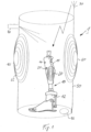
- FIG. 1 is a schematic representation of a supply system 1 for an orthopedic component 10 in the form of a prosthesis for a lower extremity.
- the orthopedic component 10 has a prosthetic knee joint with a lower leg component, an electronically controlled knee joint and a prosthetic foot.
- Several electronic devices 11, 12 are arranged on the orthopedic component 10, which are essential for the desired functioning of the orthopedic component 10.
- a computer-controlled hydraulic actuator is arranged in the lower leg component, to which, in addition to control devices, sensors, drives for valves or pumps and energy storage devices are assigned, via which a relative movement between an upper part, for example a connection for a prosthetic shaft, and the lower leg component distal to the joint axis is controlled.
- the movement resistances with regard to extension and flexion can be changed via the electronic control 11.
- a further electrical and/or electronic device 12 is arranged in the area of the ankle joint, via which the flexion and extension resistances of the foot part can be adjusted relative to the lower leg component.
- drives are arranged in the electrical and/or electronic devices 11, 12.
- a supply connection 20 is arranged on the orthopedic component 10, via which data and/or electrical energy can be received or absorbed so that both the data and the electrical energy can be stored and processed within the orthopedic component 10.
- the supply connection 20 is designed as a wireless supply connection, for example a coil device, in order to transmit energy using induction.
- a radio device 31 for receiving data can be provided in order to record and store information, for example a software update.
- a code 25 is also stored on the orthopedic component 10, by means of which the orthopedic component 10 can be clearly identified.
- the code 25 can be stored in a transponder, transmitter and/or a readable storage device or can be arranged as a bar code, QRC or other marking on the orthopedic component 10.
- the orthopedic component 10 is located in a holder 50, which in the illustrated embodiment is schematically designed as a cylindrical holder having a base in which an opening 75 is arranged as an outlet.
- a cleaning device 70 is arranged on the holder 50, which can be designed as a UV source, as a plasma generator, as a shower or washing device or as an X-ray tube. In principle, it is possible to arrange several, even different, cleaning devices 70 on a holder 50.
- the cleaning device 70 is designed as a shower device with a pump and spray element for spraying cleaning fluids, excess cleaning fluid can drain off via the drain 75.
- the orthopedic component 10 can be inserted into the holder 50 via an upper opening.
- the upper opening can be closed with a lid.
- the wall can be at least partially transparent or equipped with a window.
- An antenna 30 is arranged on the holder 50, via which data can be received on the one hand and transmitted to the radio device 31 on the other. This is indicated by the arrow.
- the antenna 30 is part of the radio device 30, 31 or a supply device 60, which are arranged on an outer wall of the holder 50 and on the orthopedic component 10, via which data is transmitted via the antenna 30 to the orthopedic components 10 and the electrical and/or electronic devices 11, 12.
- An identification device 65, 80 is also arranged on the holder 50, via which the coding 25 of the orthopedic component 10 can be read out.
- the coding 25 can be detected purely optically and identified via an image analysis. Alternatively or in addition, the transponder can be stimulated and read with the coding 25.
- a transmitter can also send the coding 25 permanently or at intervals and the signal can be received and evaluated by the identification device.
- an identification device 125 can be arranged or integrated on or in the orthopedic component 10, via which a code 165 arranged in or on the holder 50 can be read. Using the respective identification device 65, 125 and code 25, 165, it is possible to match the respective holder 50 to the orthopedic component 10 arranged in it and to determine and adapt the manner in which energy and data are transmitted and in particular which amounts of energy and which types of data are transmitted.
- the orthopedic component 10 is only placed in the holder 50.
- a receptacle or a fastening element can be arranged on the base of the holder 50 in order to fix the orthopedic component 10 in the holder 50. This can be done, for example, using form-fitting elements, Velcro fasteners, snap fasteners, tabs, straps, projections, hooks or even magnets.
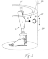
- a variant of the holder 50 is shown, which also has a base and a side wall.
- a frame is arranged at the upper end of the holder 50 in order to form an upper end, for example for leaning on or for storing the orthopaedic component 10.
- a mechanical coupling is provided via a fastening device 40, in which a first form-fitting component 42 is arranged on the holder 50 in a height-adjustable manner.
- the adjustability in particular the ability to move, is indicated by the double arrow.
- the height-adjustability makes it possible to accommodate different orthopaedic components 10 in a holder 50.
- a corresponding form-fitting element 41 is arranged on the orthopaedic component 10, which in addition to a mechanical locking with the corresponding form-fitting element 42 and the holding function implemented thereby is designed for energy transmission.
- the two form-locking elements 41, 42 are designed as a plug and a plug receptacle and thus simultaneously provide a mechanical lock and also an electrical contact.
- data can also be transmitted via the contact using the form-locking elements 41, 42.
- FIG 3 is a variant of the Figure 1 , in which a prosthesis for an upper extremity is arranged as an orthopedic component 10 within the holder 50.
- the orthopedic component 10 is held in a defined position within the holder 50 via the two form-fitting elements 41, 42.
- a cleaning device 70 is also arranged on the holder 50 in order to be able to clean the orthopedic component 10 after it has been put down.
Landscapes
- Health & Medical Sciences (AREA)
- Engineering & Computer Science (AREA)
- Life Sciences & Earth Sciences (AREA)
- Animal Behavior & Ethology (AREA)
- Veterinary Medicine (AREA)
- Public Health (AREA)
- General Health & Medical Sciences (AREA)
- Biomedical Technology (AREA)
- Heart & Thoracic Surgery (AREA)
- Oral & Maxillofacial Surgery (AREA)
- Vascular Medicine (AREA)
- Surgery (AREA)
- Cardiology (AREA)
- Transplantation (AREA)
- Power Engineering (AREA)
- Signal Processing (AREA)
- Computer Networks & Wireless Communication (AREA)
- Nuclear Medicine, Radiotherapy & Molecular Imaging (AREA)
- Pathology (AREA)
- Medical Informatics (AREA)
- Molecular Biology (AREA)
- Nursing (AREA)
- Orthopedic Medicine & Surgery (AREA)
- Electromagnetism (AREA)
- Physics & Mathematics (AREA)
- Prostheses (AREA)
Description
- Die Erfindung betrifft ein Versorgungssystem für zumindest eine orthopädietechnische Komponente, die zumindest eine elektronische und/oder elektrische Einrichtung aufweist, ein System aus einem solchen Versorgungssystem und einer orthopädietechnischen Komponenten und einem Verfahren zur Versorgung der orthopädietechnischen Komponente.
- Orthopädietechnische Komponenten können insbesondere Prothesen, Orthesen, Rollstühle oder Teile von Prothesen, Orthesen oder Rollstühlen sein, beispielsweise Orthesen- oder Prothesengelenke, Rohradapter, Prothesenhände, Drehadapter, Prothesenfüße, Prothesenschäfte, Orthesenschienen, Orthesengelenke oder Aufnahmeschalen für einen Fuß sowie Komponenten von Rollstühlen oder auch Datenlogger, Funkmodule, Sensoren, Feedbackelemente oder Speichereinrichtungen zum Speichern elektrischer Energie.
- Die Ausstattung orthopädietechnischer Komponenten mit elektrischen und/oder elektronischen Einrichtungen hat im Laufe der Entwicklung zu verbesserten, an den Patienten adaptierten oder adaptierbaren Einrichtungen geführt und zugenommen. Computergesteuerte Prothesen, Orthesen oder andere orthopädietechnische Komponenten sind zunehmend mit Antrieben ausgestattet. Ebenfalls können Dämpfereinrichtungen oder andere Aktuatoren oder Verstelleinrichtungen vorhanden sein, um eine Anpassung an den jeweiligen Patienten, die Umgebungsbedingungen und/oder gegenwärtige Bewegungssituationen vornehmen zu können. Dazu werden häufig Sensoren eingesetzt, über die Zustandsinformationen des Patienten, der Umgebung oder der orthopädietechnischen Komponente erfasst werden. Auf der Grundlage der Sensordaten werden dann über abgelegte Programme vorbestimmte Veränderungen vorgenommen, Kennlinien verändert, Antriebe aktiviert oder deaktiviert oder Gelenke freigegeben oder gesperrt.
- Um die jeweilige orthopädietechnische Komponente dauerhaft betreiben zu können, sind häufig Energiespeicher oder Energieversorgungseinrichtungen sowie ein Steuerungsprogramm der orthopädietechnischen Komponente zugeordnet. Die Energiespeicher sind bevorzugt wiederaufladbar. Das Steuerungsprogramm sieht eine Schnittstelle zu Sensoren und externen Ausleseeinrichtungen oder Datenverarbeitungsgeräten vor, über die die ausgeführten Programme und/oder aufgenommenen Sensorwerte ausgewertet und gegebenenfalls Softwareaktualisierungen implementiert werden können.
- Die
WO 2010/064063 A1 befasst sich mit einer automatischen Prothese und einer elektronischen Vorrichtung zum Steuern dieser Prothese. Die Prothese weist einen USB-Anschluss auf, durch den Software in einen Datenspeicher und elektrische Energie übertragen werden. Ein Ladegerät kann über einen Magneten an der Prothese befestigt werden, um den Ladeschaltkreis zu erkennen - Die
US 2015/351941 A1 befasst sich mit einer Prothese, die über einen kabellosen Anschluss verfügt, über den Informationen und elektrische Energie von einem externen Gerät auf die elektronische Steuerung innerhalb der Prothese übertragen werden können. - Die
EP 2 842 521 A1 offenbart ein Prothesenvorrichtung mit einem prothetischen Knöchelgelenk, einem prothetischen Fuß und einem elektromagnetischen Empfänger. Der elektromagnetische Empfänger umfasst eine Vielzahl von Spulen, die nebeneinander angeordnet sind, so dass die Durchmesser der Spulen einen Abschnitt der Prothesenvorrichtung vollständig umgeben. Der elektromagnetische Empfänger ermöglicht ein drahtloses Aufladen. - Die Versorgung mit Energie und der Datenaustausch können im angelegten Zustand der orthopädietechnischen Komponente bei Orthesen oder Prothesen oder während der Benutzung beispielsweise von Rollstühlen erfolgen. Häufig erfolgt der Energieund Datenaustausch jedoch während Phasen der Nichtbenutzung.
- Aufgabe der vorliegenden Erfindung ist es, den Daten- und/oder Energieaustausch oder allgemein die Wartung der orthopädietechnischen Komponente komfortabler zu gestalten.
- Erfindungsgemäß wird diese Aufgabe durch ein Versorgungssystem, eine System und ein Verfahren mit den Merkmalen der unabhängigen Ansprüche gelöst. Vorteilhafte Ausgestaltungen und Weiterbildung der Erfindung sind in den Unteransprüchen, der Beschreibung sowie den Figuren offenbart.
- Das erfindungsgemäße Versorgungssystem für zumindest eine orthopädietechnische Komponente, die zumindest eine elektronische und/oder elektrische Einrichtung aufweist und mit einem Versorgungsanschluss und/oder Funkeinrichtung zum Empfangen von Daten und/oder elektrischer Energie ausgestattet ist, und mit einer Halterung für die orthopädietechnische Komponente, die eine zu dem Versorgungsanschluss kompatible Versorgungseinrichtung zur Versorgung der orthopädietechnischen Komponente mit Daten und/oder Energie aufweist, wobei die Versorgungseinrichtung und der Versorgungsanschluss als kontaktlose Übertragungseinrichtung zur induktiven oder kapazitiven Übertragung oder zur Funkübertragung ausgebildet sind, sieht vor, dass das Versorgungssystem dazu eingerichtet ist, nach einer Koppelung der orthopädietechnischen Komponente mit der Versorgungseinrichtung eine Modusumschaltung der orthopädietechnischen Komponente von einem Betriebsmodus in einen Versorgungsmodus durchzuführen. Neben einer örtlichen Zuordnung der orthopädietechnischen Komponente, beispielsweise einer Orthese, einer Prothese oder eines Rollstuhls oder Teile einer Orthese, Prothese oder eines Rollstuhls, die als orthopädietechnische Komponente anzusehen sind, wird durch die Versorgungseinrichtung sichergestellt, dass während der Ruhephase oder während der Ablage der orthopädietechnischen Komponente an oder in der Halterung ein Datenaustausch und/oder Energieaustausch erfolgen kann, insbesondere eine Energiezufuhr zu einem Energiespeicher, der der orthopädietechnischen Komponente zugeordnet ist. Der Energiespeicher kann in der orthopädietechnischen Komponente integriert oder daran festgelegt sein. Ein Datenaustausch kann bidirektional erfolgen. Aufgenommene Daten der orthopädietechnischen Komponente können an die Versorgungseinrichtung übertragen werden, in der dann diese Daten ausgewertet werden können. Umgekehrt kann von der Versorgungseinrichtung ein Software-Update aufgespielt, eine Funktionsprüfung durchgeführt oder eine Fernwartung aktiviert werden, indem die Daten in die orthopädietechnische Komponente übertragen werden. Die orthopädietechnische Komponente weist dazu zumindest eine Speichereinrichtung für Daten sowie eine Verarbeitungseinrichtung oder einen Prozessor auf, um übertragene Daten zu speichern und zu verarbeiten.
- Die elektronische und/oder elektrische Einrichtung kann einen elektrischen Verbraucher aufweisen, beispielsweise einen Antrieb zum Verstellen von Bauteilen der orthopädietechnischen Komponente zueinander. Darüber hinaus besteht die Möglichkeit, dass Sensordaten in einer elektronischen Einrichtung gespeichert und bei der Kopplung der orthopädietechnischen Komponente mit der Versorgungseinrichtung ausgelesen werden.
- Die Halterung kann als Ablage oder Aufnahme mit zumindest einer Befestigungseinrichtung für die orthopädietechnische Komponente ausgebildet sein, über die die orthopädietechnische Komponente an der Halterung festlegbar ist. Neben einer Zuordnung der orthopädietechnischen Komponente zu der Versorgungseinrichtung wird darüber hinaus eine feste örtliche Zuordnung der orthopädietechnischen Komponente an der Halterung bewirkt, so dass die orthopädietechnische Komponente stets an der gleichen Stelle abgelegt und wieder aufgenommen werden kann. Insbesondere bei mehrgelenkigen Prothesen oder Orthesen wird durch die örtliche Festlegung der orthopädietechnischen Komponente zu der Halterung erreicht, dass auch während des Aufladens oder während der Versorgung der orthopädietechnischen Komponente im nicht angelegten Zustand die einzelnen Bauteile in einer definierten Zuordnung zueinander gehalten werden, so dass die orthopädietechnische Komponente nach dem Aufladen der Energiespeicher und der Aktualisierung der Software einfach wieder anlegbar ist.
- Die Befestigungseinrichtung kann zumindest ein Formschlusselement und/oder ein Kraftschlusselement aufweisen, das mit einem korrespondierend ausgestatteten Formschlusselement oder Kraftschlusselement an der orthopädietechnischen Komponente wechselwirkt. Als Kraftschlusselemente sind insbesondere Magnete vorgesehen. Als formschlüssige Befestigungseinrichtung sind Vorsprünge, Hinterschneidungen, Klettverschlüsse, Klipsverschlüsse, Absätze oder korrespondierend zu der orthopädietechnischen Komponente ausgebildeten Aufnahmen vorgesehen. Bei einem sich konisch erweiternden Prothesenschaft kann die Befestigungseinrichtung eine trichterähnliche Aufnahme aufweisen. Durch die Befestigungseinrichtung wird sichergestellt, dass die orthopädietechnische Komponente während der Kopplung mit der Versorgungseinrichtung sicher an der Halterung gehalten bleibt.
- Die Versorgungseinrichtung und der Versorgungsanschluss sind als kontaktlose Übertragungseinrichtungen ausgebildet, so dass beispielsweise bei einer kontaktlosen Übertragungseinrichtung Energie und Daten induktiv oder kapazitiv oder über Funk übertragen werden. Bei einer kontaktbehafteten Übertragung von Energie und/oder Daten ist eine Steckerverbindung vorgesehen, die auch selbstausrichtend ausgebildet sein kann. Die Steckerverbindung mit Stecker und Steckeraufnahme kann mit Formschlusselementen und/oder Kraftschlusselementen versehen sein, um eine Selbstausrichtung und somit eine Zentrierung von Stecker und Steckeraufnahme zueinander zu ermöglichen.
- In der orthopädietechnischen Komponente kann eine Kodierung abgelegt sein, die über eine in oder an der Halterung angeordnete Identifikationseinrichtung auslesbar ist. Umgekehrt kann in der orthopädietechnischen Komponente eine solche Identifikationseinrichtung angeordnet sein, über die eine in oder an der Halterung angeordnete Kodierung auslesbar ist. Somit besteht die Möglichkeit zu einer gegenseitigen Authentifizierung von Halterung und orthopädietechnischer Komponente. Darüber hinaus können mehrere Teile einer orthopädietechnischen Komponente mit elektrischen und/oder elektronischen Einrichtungen ausgestattet sein, beispielsweise bei einer Beinprothese ein Prothesenkniegelenk und ein Prothesenknöchelgelenk oder bei einer Armprothese ein Prothesenellenbogengelenk sowie eine aktuierbare Prothesenhand. Jede dieser Teile einer orthopädietechnischen Komponente kann mit einer eigenständigen Kodierung ausgestattet sein, so dass alle Kodierungen von elektrischen und/oder elektronischen Komponenten von der Halterung auslesbar sind. Durch die gegenseitige Authentifizierung von Halterung und orthopädietechnischen Komponenten und deren Teile ist es möglich, den Umfang und die Art der übermittelten Energie bzw. der übermittelten Daten zu verändern. Dadurch ist es möglich, eine Halterung für mehrere orthopädietechnische Komponenten vorzusehen. Jede Halterung kann die ihr zugeordnete orthopädietechnische Komponente identifizieren und daran angepasst die notwendige Energiemenge, Energieart sowie Steuerungsprogramme, Daten oder ähnliches übermitteln oder auslesen.
- An der Halterung kann eine Reinigungsvorrichtung angeordnet sein, um während des Datenaustausches oder der Energieversorgung die orthopädietechnische Komponente reinigen zu können und für den weiteren Gebrauch vorzubereiten. Die Reinigungsvorrichtung kann eine UV-Quelle, einen Plasmagenerator und/oder eine Röntgenröhre aufweisen, um durch eine entsprechende Bestrahlung oder Ionisierung die orthopädietechnische Komponente zu reinigen oder zu desinfizieren. Insbesondere bei unmittelbar auf der Haut getragenen orthopädietechnischen Komponenten ist eine solche integrierte Reinigungsvorrichtung vorteilhaft.
- Die Erfindung betrifft ebenfalls ein System aus einem Versorgungssystem, wie es voranstehend beschrieben worden ist, und einer orthopädietechnischen Einrichtung, die über das Versorgungssystem mit Daten und/oder Energie versorgt werden kann. Die Ausgestaltung des Versorgungssystems und der orthopädietechnischen Einrichtung als Gesamtsystem erleichtert die gegenseitige Abstimmung und die reibungslose und störungsarme Versorgung mit Daten und/oder Energie.
- Das Verfahren zur Versorgung einer orthopädietechnischen Komponente mit Daten und/oder Energie, wobei die orthopädietechnische Komponente zumindest eine elektronische und/oder elektrische Einrichtung aufweist und mit einem Versorgungsanschluss zum Empfangen von Daten und/oder elektrischer Energie ausgestattet ist, sieht vor, dass die orthopädietechnische Komponente in oder an einer Halterung, in oder an der eine zu dem Versorgunganschluss kompatible Versorgungseinrichtung zur Versorgung der orthopädietechnischen Komponente mit Daten und/oder Energie angeordnet ist, befestigt wird, dass der Versorgungsanschluss mit der Versorgungseinrichtung gekoppelt wird und automatisch nach der Kopplung der Versorgungseinrichtung mit dem Versorgungsanschluss eine Daten- und/oder Energieübertragung stattfindet. Sobald die orthopädietechnische Komponente in der Halterung abgelegt und auf der Halterung aufgelegt wird, finden eine Datenwartung und eine gegebenenfalls notwendige Energieübertragung statt. Vor der Daten- und/oder Energieübertragung kann eine Identifizierung der orthopädietechnischen Komponente erfolgen, beispielsweise durch Abfragen einer Kodierung der zumindest einen orthopädietechnischen Komponente oder aller orthopädietechnischen Komponenten oder Teile von orthopädietechnischen Komponenten mit mehreren elektronischen und/oder elektrischen Einrichtungen.
- In Abhängigkeit von der orthopädietechnischen Komponente können dann abgestimmte Daten übermittelt und eine Funktionsüberprüfung eingeleitet werden. Bei einer Funktionsüberprüfung kann der komplette Funktionsumfang der orthopädietechnischen Komponente überprüft werden, beispielsweise eine maximale Verschwenkung von Elementen der orthopädietechnischen Komponente zueinander initiiert und überprüft werden, ob der maximale Verfahrweg und Verschwenkbereich erreicht wird. Auch können Verstellungen von Widerständen sowie andere Funktionsüberprüfungen während der Versorgung der orthopädietechnischen Komponente mit Daten und/oder Energie durchgeführt werden.
- Nach der Kopplung der Versorgungseinrichtung mit dem Versorgungsanschluss der orthopädietechnischen Komponente erfolgt eine Modusumschaltung der orthopädietechnischen Komponente. Von einem Betriebsmodus wird nach der Kopplung mit der Versorgungseinrichtung in einen Versorgungsmodus umgeschaltet, bei dem einige Funktionen ausgeschaltet und andere aktiviert werden, um zu verhindern, dass die Funktionsüberprüfung im angelegten Zustand der orthopädietechnischen Komponente oder während deren eigentlichen Benutzung durchgeführt wird.
- Im Versorgungsmodus können Zusatzfunktionen aktiviert werden, beispielsweise kann eine Musikwiedergabe stattfinden, um die Wartezeit zur Wiederinbetriebnahme der orthopädietechnischen Komponente möglichst angenehm zu gestalten.
- Über eine gegenseitige Authentifizierung wird verhindert, dass falsche Daten übertragen werden oder dass sicherheitsrelevante Funktionen oder ein Quellcode ausgelesen und manipuliert werden.
- Nachfolgend werden die Ausführungsbeispiele anhand der beigefügten Figuren näher erläutert. Es zeigen:
- Figur 1
- eine erste Ausführungsform eines Versorgungssystems für eine Prothese einer unteren Extremität;
- Figur 2
- eine zweite Ausführungsform des Versorgungssystems; sowie
- Figur 3
- ein Versorgungssystem für eine Prothese einer oberen Extremität.
- In der
Figur 1 ist in einer schematischen Darstellung ein Versorgungssystem 1 für eine orthopädietechnische Komponente 10 in Gestalt einer Prothese für eine untere Extremität dargestellt. Die orthopädietechnische Komponente 10 weist ein Prothesenkniegelenk mit einer Unterschenkelkomponente, einem elektronisch gesteuerten Kniegelenk sowie einem Prothesenfuß auf. An der orthopädietechnischen Komponente 10 sind mehrere elektronische Einrichtungen 11, 12 angeordnet, die für die gewünschte Funktionsweise der orthopädietechnischen Komponente 10 wesentlich sind. In der Unterschenkelkomponente ist ein rechnergesteuerter Hydraulikaktuator angeordnet, dem neben Steuerungseinrichtungen Sensoren, Antriebe für Ventile oder Pumpen und Energiespeicher zugeordnet sind, über die eine Relativbewegung zwischen einem Oberteil, beispielsweise einem Anschluss für einen Prothesenschaft, und der Unterschenkelkomponente distal zu der Gelenkachse gesteuert wird. Die Bewegungswiderstände hinsichtlich der Extension und Flexion können über die elektronische Steuerung 11 verändert werden. - Weiterhin ist im Bereich des Knöchelgelenkes eine weitere elektrische und/oder elektronische Einrichtung 12 angeordnet, über die Flexions- und Extensionswiderstände des Fußteils relativ zu der Unterschenkelkomponente eingestellt werden können. Alternativ oder ergänzend sind Antriebe in den elektrischen und/oder elektronischen Einrichtungen 11, 12 angeordnet. An der orthopädietechnischen Komponente 10 ist ein Versorgungsanschluss 20 angeordnet, über den Daten und/oder elektrische Energie empfangen oder aufgenommen werden können, damit sowohl die Daten als auch die elektrische Energie innerhalb der orthopädietechnischen Komponente 10 gespeichert und verarbeitet werden können. In dem dargestellten Ausführungsbeispiel ist der Versorgungsanschluss 20 als ein drahtloser Versorgungsanschluss ausgebildet, beispielsweise eine Spuleneinrichtung, um unter Nutzung der Induktion Energie zu übertragen. Darüber hinaus kann eine Funkeinrichtung 31 zum Empfangen von Daten vorgesehen sein, um Informationen, beispielsweise ein Softwareupdate, aufzunehmen und zu speichern.
- Ebenfalls ist an der orthopädietechnischen Komponente 10 eine Kodierung 25 abgelegt, über die die orthopädietechnische Komponente 10 eindeutig identifizierbar ist. Die Kodierung 25 kann in einem Transponder, Sender und/oder einer auslesbaren Speichereinrichtung abgelegt sein oder als Strichcode, QRC oder andere Markierung an der orthopädietechnischen Komponente 10 angeordnet sein. Die orthopädietechnische Komponente 10 befindet sich in einer Halterung 50, die in dem dargestellten Ausführungsbeispiel schematisch als eine zylindrische Halterung ausgebildet ist, die einen Boden aufweist, in dem eine Öffnung 75 als ein Auslass angeordnet ist. An der Halterung 50 ist eine Reinigungsvorrichtung 70 angeordnet, die als eine UV-Quelle, als ein Plasmagenerator, als eine Dusch- oder Wascheinrichtung oder als eine Röntgenröhre ausgebildet sein kann. Grundsätzlich ist es möglich, mehrere, auch unterschiedliche Reinigungsvorrichtungen 70 an einer Halterung 50 anzuordnen. Ist die Reinigungsvorrichtung 70 als eine Duscheinrichtung mit Pumpe und Sprühelement zum Versprühen von Reinigungsflüssigkeiten ausgebildet, kann überflüssige Reinigungsflüssigkeit über den Abfluss 75 ablaufen. Die orthopädietechnische Komponente 10 kann über eine obere Öffnung in die Halterung 50 eingestellt werden. Die obere Öffnung kann über einen Deckel verschließbar sein. Die Wand kann zumindest teilweise durchsichtig oder mit einem Fenster ausgestattet sein.
- An der Halterung 50 ist eine Antenne 30 angeordnet, über die einerseits Daten empfangen und andererseits Daten zu der Funkeinrichtung 31 übermittelt werden können. Dies ist durch den Pfeil angedeutet. Die Antenne 30 ist Teil der Funkeinrichtung 30, 31 oder einer Versorgungseinrichtung 60, die an einer Außenwand der Halterung 50 und an der orthopädietechnischen Komponente 10 angeordnet sind, über die Daten über die Antenne 30 an die orthopädietechnische Komponenten 10 und die elektrischen und/oder elektronischen Einrichtungen 11, 12 übermittelt werden. Ebenfalls an der Halterung 50 ist eine Identifikationseinrichtung 65, 80 angeordnet, über die die Kodierung 25 der orthopädietechnischen Komponente 10 auslesbar ist. Die Kodierung 25 kann rein optisch erfasst und über eine Bildauswertung identifiziert werden. Alternativ oder ergänzend kann der Transponder mit der Kodierung 25 angeregt und ausgelesen werden. Ebenfalls kann ein Sender die Kodierung 25 permanent oder in Zeitabständen senden und das Signal von der Identifikationseinrichtung empfangen und ausgewertet werden.
- Alternativ oder ergänzend kann an oder in der orthopädietechnischen Komponente 10 eine Identifikationseinrichtung 125 angeordnet oder integriert sein, über die eine in oder an der Halterung 50 angeordnete Kodierung 165 auslesbar ist. Über die jeweilige Identifikationseinrichtung 65, 125 und Kodierung 25, 165 ist es möglich, die jeweilige Halterung 50 auf die in ihr angeordnete orthopädietechnische Komponente 10 abzustimmen und die Art und Weise, wie Energie und Daten übertragen werden und insbesondere, welche Energiemengen und welche Arten von Daten übertragen werden, festzulegen und anzupassen.
- In dem in der
Figur 1 dargestellten Ausführungsbeispiel ist die orthopädietechnische Komponente 10 nur in der Halterung 50 abgestellt. An dem Boden der Halterung 50 kann beispielsweise eine Aufnahme oder ein Befestigungselement angeordnet sein, um die orthopädietechnische Komponente 10 in der Halterung 50 zu fixieren. Dies kann beispielsweise über Formschlusselemente, Klettverschlüsse, Schnappverschlüsse, Laschen, Riemen, Vorsprünge, Haken oder auch Magnete geschehen. - In der
Figur 2 ist eine Variante der Halterung 50 gezeigt, die ebenfalls einen Boden und eine Seitenwand aufweist. An dem oberen Ende der Halterung 50 ist ein Rahmen angeordnet, um einen oberen Abschluss, beispielsweise zum Anlehnen oder zur Ablage der orthopädietechnischen Komponente 10 auszubilden. Anders als bei derFigur 1 ist in der Ausführungsform gemäßFigur 2 neben einer drahtlosen Datenübertragung über die Antenne 30 eine mechanische Kopplung über eine Befestigungseinrichtung 40 vorgesehen, bei der an der Halterung 50 eine erste Formschlusskomponente 42 höhenverstellbar angeordnet ist. Die Verstellbarkeit, insbesondere Verschieblichkeit ist über den Doppelpfeil angedeutet. Über die Höhenverlagerbarkeit ist es möglich, unterschiedliche orthopädietechnische Komponenten 10 in einer Halterung 50 aufzunehmen. An der orthopädietechnischen Komponente 10 ist ein korrespondierendes Formschlusselement 41 angeordnet, das neben einer mechanischen Verriegelung mit dem korrespondierenden Formschlusselement 42 und der dadurch verwirklichten Haltefunktion zur Energieübertragung ausgebildet ist. Das heißt, dass die beiden Formschlusselemente 41, 42 als Stecker und Steckaufnahme ausgebildet sind und somit gleichzeitig geben einer mechanischen Verriegelung auch eine elektrische Kontaktierung ausbilden. Neben einer reinen Energieübertragung kann zusätzlich auch eine Datenübertragung über die Kontaktierung mittels der Formschlusselemente 41, 42 erfolgen. - In der
Figur 3 ist eine Variante derFigur 1 dargestellt, bei der eine Prothese für eine obere Extremität als orthopädietechnische Komponente 10 innerhalb der Halterung 50 angeordnet ist. Über die beiden Formschlusselemente 41, 42 wird die orthopädietechnische Komponente 10 in einer definierten Position innerhalb der Halterung 50 gehalten. Ebenfalls ist an der Halterung 50 eine Reinigungsvorrichtung 70 angeordnet, um nach dem Ablegen der orthopädietechnischen Komponente 10 diese reinigen zu können.
Claims (10)
- Versorgungssystem für zumindest eine orthopädietechnische Komponente (10), die zumindest eine elektronische und/oder elektrische Einrichtung (11, 12) aufweist und mit einem Versorgungsanschluss (20) und/oder einer Funkeinrichtung (31) zum Empfangen von Daten und/oder elektrischer Energie ausgestattet ist, das Versorgungssystem hat eine Halterung (50) für die orthopädietechnische Komponente (10), die eine zu dem Versorgungsanschluss (20) und/oder der Funkeinrichtung (31) kompatible Versorgungseinrichtung (30, 60) zur Versorgung der orthopädietechnischen Komponente (10) mit Daten und/oder Energie aufweist, wobei die Versorgungseinrichtung (60) und der Versorgungsanschluss (20) als kontaktlose Übertragungseinrichtungen zur induktiven oder kapazitiven Übertragung oder zur Funkübertragung ausgebildet sind, dadurch gekennzeichnet, dass das Versorgungssystem dazu eingerichtet ist, nach einer Koppelung der orthopädietechnischen Komponente (10) mit der Versorgungseinrichtung (30, 60) eine Modusumschaltung der orthopädietechnischen Komponente (10) von einem Betriebsmodus in einen Versorgungsmodus durchzuführen.
- Versorgungssystem nach Anspruch 1, dadurch gekennzeichnet, dass die Halterung (50) als Ablage oder Aufnahme mit zumindest einer Befestigungseinrichtung (40) ausgebildet ist, über die die orthopädietechnische Komponente (10) an der Halterung (50) festlegbar ist.
- Versorgungssystem nach Anspruch 2, dadurch gekennzeichnet, dass die Befestigungseinrichtung (40) zumindest ein Formschlusselement (42) und/oder ein Kraftschlusselement aufweist, das mit einem korrespondierend ausgestatteten Formschlusselement (41) oder Kraftschlusselement an der orthopädietechnischen Komponente (10) wechselwirkt.
- Versorgungssystem nach einem der voranstehenden Ansprüche, dadurch gekennzeichnet, dass in der orthopädietechnischen Komponente (10) eine Kodierung (25) abgelegt ist, die über eine in oder an der Halterung (50) angeordnete Identifikationseinrichtung (65, 80) auslesbar ist und/oder dass in der orthopädietechnischen Komponente (10) eine Identifikationseinrichtung (125) angeordnet ist, über die eine in oder an der Halterung (50) angeordnete Kodierung (165) auslesbar ist.
- Versorgungssystem nach einem der voranstehenden Ansprüche, dadurch gekennzeichnet, dass an der Halterung (50) eine Reinigungsvorrichtung (70) angeordnet ist.
- Versorgungssystem nach Anspruch 5, dadurch gekennzeichnet, dass die Reinigungsvorrichtung (70) eine UV-Quelle, einen Plasmagenerator und/oder eine Röntgenröhre aufweist.
- System aus einem Versorgungssystem nach einem der voranstehenden Ansprüche und einer orthopädietechnischen Komponente.
- Verfahren zur Versorgung einer orthopädietechnischen Komponente (10) mit Daten und/oder Energie, wobei die orthopädietechnische Komponente (10) zumindest eine elektronische und/oder elektrische Einrichtung (11, 12) aufweist und mit einem Versorgungsanschluss (20) und/oder einer Funkeinrichtung (31) zum Empfangen von Daten und/oder elektrischer Energie ausgestattet ist, wobei die orthopädietechnische Komponente (10) in oder an einer Halterung (50) und an einem Versorgungssystem nach einem der voranstehenden Ansprüche, in oder an der eine zu dem Versorgungsanschluss (20) und/oder Funkeinrichtung (31) kompatible Versorgungseinrichtung (30, 60) zur Versorgung der orthopädietechnischen Komponente (10) mit Daten und/oder Energie angeordnet ist, befestigt wird, der Versorgungsanschluss (209 und/oder die Funkeinrichtung (31) mit der Versorgungseinrichtung (30, 60) gekoppelt wird und automatisch eine Daten- und/oder Energieübertragung stattfindet, dadurch gekennzeichnet, dass nach der Koppelung mit der Versorgungseinrichtung (30, 60) eine Modusumschaltung der orthopädietechnischen Komponente (10) von einem Betriebsmodus in einen Versorgungsmodus durchgeführt wird.
- Verfahren nach Anspruch 8, dadurch gekennzeichnet, dass vor der Datenund/oder Energieübertragung eine Identifizierung der orthopädietechnischen Komponente (10) erfolgt.
- Verfahren nach Anspruch 9, dadurch gekennzeichnet, dass in Abhängigkeit von der orthopädietechnischen Komponente (10) auf die jeweilige orthopädietechnische Komponente (10) abgestimmte Daten übermittelt oder Funktionsüberprüfungen eingeleitet werden.
Applications Claiming Priority (2)
| Application Number | Priority Date | Filing Date | Title |
|---|---|---|---|
| DE102017131195.5A DE102017131195A1 (de) | 2017-12-22 | 2017-12-22 | Versorgungssystem für orthopädietechnische Komponente und Verfahren |
| PCT/EP2018/085663 WO2019121792A1 (de) | 2017-12-22 | 2018-12-18 | Versorgungssystem für orthopädietechnische komponente und verfahren |
Publications (2)
| Publication Number | Publication Date |
|---|---|
| EP3727212A1 EP3727212A1 (de) | 2020-10-28 |
| EP3727212B1 true EP3727212B1 (de) | 2024-06-05 |
Family
ID=64899321
Family Applications (1)
| Application Number | Title | Priority Date | Filing Date |
|---|---|---|---|
| EP18826306.5A Active EP3727212B1 (de) | 2017-12-22 | 2018-12-18 | Versorgungssystem für orthopädietechnische komponente und verfahren |
Country Status (4)
| Country | Link |
|---|---|
| US (1) | US11916583B2 (de) |
| EP (1) | EP3727212B1 (de) |
| DE (1) | DE102017131195A1 (de) |
| WO (1) | WO2019121792A1 (de) |
Families Citing this family (5)
| Publication number | Priority date | Publication date | Assignee | Title |
|---|---|---|---|---|
| DE102019118422B3 (de) * | 2019-07-08 | 2021-01-07 | Otto Bock Healthcare Products Gmbh | Aktuator und Wärmespeicher für Aktuator |
| DE102020125255A1 (de) | 2020-09-28 | 2022-03-31 | Otto Bock Healthcare Products Gmbh | Verfahren zum Einrichten einer Steuerung und orthopädietechnische sowie Computerprogrammprodukt |
| NL2027046B1 (en) * | 2020-12-04 | 2022-07-06 | Axiles Bionics Bv | Data transfer method for a prosthesis or orthosis and system thereof |
| DE102021133497A1 (de) * | 2021-12-16 | 2023-06-22 | Otto Bock Healthcare Products Gmbh | Aktuator und orthopädietechnische Gelenkeinrichtung und Verfahren zu deren Steuerung |
| JP2025529025A (ja) * | 2022-09-14 | 2025-09-04 | ビエン - エア ホールディング ソシエテ アノニム | 医療機器を再処理するためのシステム |
Citations (1)
| Publication number | Priority date | Publication date | Assignee | Title |
|---|---|---|---|---|
| EP2842521A1 (de) * | 2013-08-27 | 2015-03-04 | Freedom Innovations, LLC | Drahtloses Laden für prothetische Vorrichtung |
Family Cites Families (10)
| Publication number | Priority date | Publication date | Assignee | Title |
|---|---|---|---|---|
| US4443902A (en) * | 1981-07-06 | 1984-04-24 | Baer Richard K | Invalid walker and transfer device |
| US5716330A (en) * | 1995-07-13 | 1998-02-10 | Goldman; David A. | Body and limb position/motion detector and power assist apparatus and method |
| US7198071B2 (en) * | 2003-05-02 | 2007-04-03 | Össur Engineering, Inc. | Systems and methods of loading fluid in a prosthetic knee |
| CA2611492C (en) * | 2005-06-10 | 2014-05-13 | The Ohio Willow Wood Company | Prosthetic device utilizing electric vacuum pump |
| US20160250045A1 (en) * | 2005-06-10 | 2016-09-01 | The Ohio Willow Wood Company | Prosthetic device utilizing electric vacuum pump |
| ES2659713T3 (es) * | 2008-04-30 | 2018-03-19 | Officine Ortopediche Rizzoli S.R.L. | Prótesis automática para personas con amputación por encima de la rodilla |
| WO2013123286A1 (en) * | 2012-02-16 | 2013-08-22 | Bomkamp Katherine E | Pain free socket system and associated method |
| DE102012015483B3 (de) | 2012-08-07 | 2014-01-16 | Otto Bock Healthcare Gmbh | Elektrodenanordnung für eine Plasmabehandlung und Vorrichtung zur Herstellung einer transkutanen Verbindung |
| EP3317053B1 (de) * | 2015-12-14 | 2022-03-16 | Parker-Hannifin Corporation | Sicherheitsüberwachungs- und kontrollsystem und -verfahren für eine exoskelettvorrichtung für bebeinte mobilität |
| KR101690774B1 (ko) * | 2016-06-30 | 2016-12-28 | 만드로 주식회사 | 전자의수 충전용 거치대 |
-
2017
- 2017-12-22 DE DE102017131195.5A patent/DE102017131195A1/de not_active Withdrawn
-
2018
- 2018-12-18 US US15/733,263 patent/US11916583B2/en active Active
- 2018-12-18 EP EP18826306.5A patent/EP3727212B1/de active Active
- 2018-12-18 WO PCT/EP2018/085663 patent/WO2019121792A1/de not_active Ceased
Patent Citations (1)
| Publication number | Priority date | Publication date | Assignee | Title |
|---|---|---|---|---|
| EP2842521A1 (de) * | 2013-08-27 | 2015-03-04 | Freedom Innovations, LLC | Drahtloses Laden für prothetische Vorrichtung |
Also Published As
| Publication number | Publication date |
|---|---|
| DE102017131195A1 (de) | 2019-06-27 |
| WO2019121792A1 (de) | 2019-06-27 |
| US20210099193A1 (en) | 2021-04-01 |
| US11916583B2 (en) | 2024-02-27 |
| EP3727212A1 (de) | 2020-10-28 |
Similar Documents
| Publication | Publication Date | Title |
|---|---|---|
| EP3727212B1 (de) | Versorgungssystem für orthopädietechnische komponente und verfahren | |
| DE102016114075B3 (de) | Orthopädietechnisches System und Verfahren zu dessen Steuerung | |
| EP3174505B1 (de) | Prothesenfuss, system aus prothesenfuss und einem schuh sowie verfahren zum anpassen der absatzhöhe eines prothesenfusses | |
| EP1158940A1 (de) | Vorrichtung und verfahren zur fernwartung einer elektronisch ansteuerbaren prothese | |
| EP2922506B1 (de) | Modulares orthesensystem und kit zu dessen anpassung | |
| DE102005019306A1 (de) | Energieoptimierte Datenübertragung eines medizinischen Geräts | |
| DE202013009698U1 (de) | Menschliche nicht redundante Parallelkinematik für eine Orthese oder ein Exoskelett mit seitlichen Kopplungsstellen | |
| AR243761A1 (es) | Dispositivo para reconstruir las articulaciones corporales, particularmente las articulaciones de la muneca. | |
| EP2129340B1 (de) | Prothese mit ladbarem, elektrischem energiespeicher | |
| ATE266986T1 (de) | Gliederprothesen | |
| EP2962726A1 (de) | System zur anregung von phantomempfindungen | |
| DE102018133078A1 (de) | Verfahren zur Auswertung von Nutzungsdaten | |
| Gherardini et al. | The myokinetic interface: Implanting permanent magnets to restore the sensory-motor control loop in amputees | |
| EP2498728A1 (de) | System mit zumindest einer orthopädietechnischen einrichtung und einer fernbedienung | |
| EP2818718B1 (de) | Vakuumpumpstand mit drahtloser Bedieneinheit | |
| DE10311187B4 (de) | Orthopädietechnisches Hilfsmittel mit einer Verriegelungsvorrichtung | |
| WO2008142552A2 (en) | Multiple joint linkage device | |
| Kiani et al. | Evaluation of a closed loop inductive power transmission system on an awake behaving animal subject | |
| DE202010009441U1 (de) | Transportvorrichtung mit Einrichtung zur Transportsicherung für Gehörknöchelchenprothesen | |
| Ahsan et al. | Design and development of an electromyography sensor actuated prosthetic arm | |
| EP4138740B1 (de) | Verfahren zum uebertragen von daten | |
| DE102010017110B4 (de) | Uhrenbeweger | |
| DE102007054305A1 (de) | Sensorapplikation mit einer Trägerstruktur und einem Sensorband, Trägerstruktur, Sensorband und Verfahren zum Betreiben der Sonsorapplikation | |
| DE202011052503U1 (de) | Orthesengelenk zum Unterstützen eines anatomischen Kniegelenks | |
| DE102018218234A1 (de) | Patientenindividuelle Handorthese |
Legal Events
| Date | Code | Title | Description |
|---|---|---|---|
| STAA | Information on the status of an ep patent application or granted ep patent |
Free format text: STATUS: UNKNOWN |
|
| STAA | Information on the status of an ep patent application or granted ep patent |
Free format text: STATUS: THE INTERNATIONAL PUBLICATION HAS BEEN MADE |
|
| PUAI | Public reference made under article 153(3) epc to a published international application that has entered the european phase |
Free format text: ORIGINAL CODE: 0009012 |
|
| STAA | Information on the status of an ep patent application or granted ep patent |
Free format text: STATUS: REQUEST FOR EXAMINATION WAS MADE |
|
| 17P | Request for examination filed |
Effective date: 20200707 |
|
| AK | Designated contracting states |
Kind code of ref document: A1 Designated state(s): AL AT BE BG CH CY CZ DE DK EE ES FI FR GB GR HR HU IE IS IT LI LT LU LV MC MK MT NL NO PL PT RO RS SE SI SK SM TR |
|
| AX | Request for extension of the european patent |
Extension state: BA ME |
|
| DAV | Request for validation of the european patent (deleted) | ||
| DAX | Request for extension of the european patent (deleted) | ||
| STAA | Information on the status of an ep patent application or granted ep patent |
Free format text: STATUS: EXAMINATION IS IN PROGRESS |
|
| 17Q | First examination report despatched |
Effective date: 20220725 |
|
| GRAP | Despatch of communication of intention to grant a patent |
Free format text: ORIGINAL CODE: EPIDOSNIGR1 |
|
| STAA | Information on the status of an ep patent application or granted ep patent |
Free format text: STATUS: GRANT OF PATENT IS INTENDED |
|
| INTG | Intention to grant announced |
Effective date: 20231026 |
|
| GRAJ | Information related to disapproval of communication of intention to grant by the applicant or resumption of examination proceedings by the epo deleted |
Free format text: ORIGINAL CODE: EPIDOSDIGR1 |
|
| STAA | Information on the status of an ep patent application or granted ep patent |
Free format text: STATUS: EXAMINATION IS IN PROGRESS |
|
| GRAP | Despatch of communication of intention to grant a patent |
Free format text: ORIGINAL CODE: EPIDOSNIGR1 |
|
| STAA | Information on the status of an ep patent application or granted ep patent |
Free format text: STATUS: GRANT OF PATENT IS INTENDED |
|
| INTC | Intention to grant announced (deleted) | ||
| INTG | Intention to grant announced |
Effective date: 20240112 |
|
| GRAS | Grant fee paid |
Free format text: ORIGINAL CODE: EPIDOSNIGR3 |
|
| GRAA | (expected) grant |
Free format text: ORIGINAL CODE: 0009210 |
|
| STAA | Information on the status of an ep patent application or granted ep patent |
Free format text: STATUS: THE PATENT HAS BEEN GRANTED |
|
| AK | Designated contracting states |
Kind code of ref document: B1 Designated state(s): AL AT BE BG CH CY CZ DE DK EE ES FI FR GB GR HR HU IE IS IT LI LT LU LV MC MK MT NL NO PL PT RO RS SE SI SK SM TR |
|
| REG | Reference to a national code |
Ref country code: CH Ref legal event code: EP |
|
| REG | Reference to a national code |
Ref country code: DE Ref legal event code: R096 Ref document number: 502018014716 Country of ref document: DE |
|
| REG | Reference to a national code |
Ref country code: IE Ref legal event code: FG4D Free format text: LANGUAGE OF EP DOCUMENT: GERMAN |
|
| REG | Reference to a national code |
Ref country code: LT Ref legal event code: MG9D |
|
| PG25 | Lapsed in a contracting state [announced via postgrant information from national office to epo] |
Ref country code: BG Free format text: LAPSE BECAUSE OF FAILURE TO SUBMIT A TRANSLATION OF THE DESCRIPTION OR TO PAY THE FEE WITHIN THE PRESCRIBED TIME-LIMIT Effective date: 20240605 |
|
| REG | Reference to a national code |
Ref country code: NL Ref legal event code: MP Effective date: 20240605 |
|
| PG25 | Lapsed in a contracting state [announced via postgrant information from national office to epo] |
Ref country code: FI Free format text: LAPSE BECAUSE OF FAILURE TO SUBMIT A TRANSLATION OF THE DESCRIPTION OR TO PAY THE FEE WITHIN THE PRESCRIBED TIME-LIMIT Effective date: 20240605 Ref country code: HR Free format text: LAPSE BECAUSE OF FAILURE TO SUBMIT A TRANSLATION OF THE DESCRIPTION OR TO PAY THE FEE WITHIN THE PRESCRIBED TIME-LIMIT Effective date: 20240605 |
|
| PG25 | Lapsed in a contracting state [announced via postgrant information from national office to epo] |
Ref country code: GR Free format text: LAPSE BECAUSE OF FAILURE TO SUBMIT A TRANSLATION OF THE DESCRIPTION OR TO PAY THE FEE WITHIN THE PRESCRIBED TIME-LIMIT Effective date: 20240906 |
|
| PG25 | Lapsed in a contracting state [announced via postgrant information from national office to epo] |
Ref country code: ES Free format text: LAPSE BECAUSE OF FAILURE TO SUBMIT A TRANSLATION OF THE DESCRIPTION OR TO PAY THE FEE WITHIN THE PRESCRIBED TIME-LIMIT Effective date: 20240605 |
|
| PG25 | Lapsed in a contracting state [announced via postgrant information from national office to epo] |
Ref country code: LV Free format text: LAPSE BECAUSE OF FAILURE TO SUBMIT A TRANSLATION OF THE DESCRIPTION OR TO PAY THE FEE WITHIN THE PRESCRIBED TIME-LIMIT Effective date: 20240605 |
|
| PG25 | Lapsed in a contracting state [announced via postgrant information from national office to epo] |
Ref country code: NO Free format text: LAPSE BECAUSE OF FAILURE TO SUBMIT A TRANSLATION OF THE DESCRIPTION OR TO PAY THE FEE WITHIN THE PRESCRIBED TIME-LIMIT Effective date: 20240905 Ref country code: LV Free format text: LAPSE BECAUSE OF FAILURE TO SUBMIT A TRANSLATION OF THE DESCRIPTION OR TO PAY THE FEE WITHIN THE PRESCRIBED TIME-LIMIT Effective date: 20240605 Ref country code: HR Free format text: LAPSE BECAUSE OF FAILURE TO SUBMIT A TRANSLATION OF THE DESCRIPTION OR TO PAY THE FEE WITHIN THE PRESCRIBED TIME-LIMIT Effective date: 20240605 Ref country code: GR Free format text: LAPSE BECAUSE OF FAILURE TO SUBMIT A TRANSLATION OF THE DESCRIPTION OR TO PAY THE FEE WITHIN THE PRESCRIBED TIME-LIMIT Effective date: 20240906 Ref country code: FI Free format text: LAPSE BECAUSE OF FAILURE TO SUBMIT A TRANSLATION OF THE DESCRIPTION OR TO PAY THE FEE WITHIN THE PRESCRIBED TIME-LIMIT Effective date: 20240605 Ref country code: ES Free format text: LAPSE BECAUSE OF FAILURE TO SUBMIT A TRANSLATION OF THE DESCRIPTION OR TO PAY THE FEE WITHIN THE PRESCRIBED TIME-LIMIT Effective date: 20240605 Ref country code: BG Free format text: LAPSE BECAUSE OF FAILURE TO SUBMIT A TRANSLATION OF THE DESCRIPTION OR TO PAY THE FEE WITHIN THE PRESCRIBED TIME-LIMIT Effective date: 20240605 Ref country code: RS Free format text: LAPSE BECAUSE OF FAILURE TO SUBMIT A TRANSLATION OF THE DESCRIPTION OR TO PAY THE FEE WITHIN THE PRESCRIBED TIME-LIMIT Effective date: 20240905 |
|
| PG25 | Lapsed in a contracting state [announced via postgrant information from national office to epo] |
Ref country code: NL Free format text: LAPSE BECAUSE OF FAILURE TO SUBMIT A TRANSLATION OF THE DESCRIPTION OR TO PAY THE FEE WITHIN THE PRESCRIBED TIME-LIMIT Effective date: 20240605 |
|
| PG25 | Lapsed in a contracting state [announced via postgrant information from national office to epo] |
Ref country code: NL Free format text: LAPSE BECAUSE OF FAILURE TO SUBMIT A TRANSLATION OF THE DESCRIPTION OR TO PAY THE FEE WITHIN THE PRESCRIBED TIME-LIMIT Effective date: 20240605 |
|
| PG25 | Lapsed in a contracting state [announced via postgrant information from national office to epo] |
Ref country code: PT Free format text: LAPSE BECAUSE OF FAILURE TO SUBMIT A TRANSLATION OF THE DESCRIPTION OR TO PAY THE FEE WITHIN THE PRESCRIBED TIME-LIMIT Effective date: 20241007 |
|
| PG25 | Lapsed in a contracting state [announced via postgrant information from national office to epo] |
Ref country code: PT Free format text: LAPSE BECAUSE OF FAILURE TO SUBMIT A TRANSLATION OF THE DESCRIPTION OR TO PAY THE FEE WITHIN THE PRESCRIBED TIME-LIMIT Effective date: 20241007 |
|
| PG25 | Lapsed in a contracting state [announced via postgrant information from national office to epo] |
Ref country code: PL Free format text: LAPSE BECAUSE OF FAILURE TO SUBMIT A TRANSLATION OF THE DESCRIPTION OR TO PAY THE FEE WITHIN THE PRESCRIBED TIME-LIMIT Effective date: 20240605 |
|
| PG25 | Lapsed in a contracting state [announced via postgrant information from national office to epo] |
Ref country code: EE Free format text: LAPSE BECAUSE OF FAILURE TO SUBMIT A TRANSLATION OF THE DESCRIPTION OR TO PAY THE FEE WITHIN THE PRESCRIBED TIME-LIMIT Effective date: 20240605 |
|
| PG25 | Lapsed in a contracting state [announced via postgrant information from national office to epo] |
Ref country code: IS Free format text: LAPSE BECAUSE OF FAILURE TO SUBMIT A TRANSLATION OF THE DESCRIPTION OR TO PAY THE FEE WITHIN THE PRESCRIBED TIME-LIMIT Effective date: 20241005 |
|
| PG25 | Lapsed in a contracting state [announced via postgrant information from national office to epo] |
Ref country code: CZ Free format text: LAPSE BECAUSE OF FAILURE TO SUBMIT A TRANSLATION OF THE DESCRIPTION OR TO PAY THE FEE WITHIN THE PRESCRIBED TIME-LIMIT Effective date: 20240605 |
|
| PG25 | Lapsed in a contracting state [announced via postgrant information from national office to epo] |
Ref country code: RO Free format text: LAPSE BECAUSE OF FAILURE TO SUBMIT A TRANSLATION OF THE DESCRIPTION OR TO PAY THE FEE WITHIN THE PRESCRIBED TIME-LIMIT Effective date: 20240605 Ref country code: SK Free format text: LAPSE BECAUSE OF FAILURE TO SUBMIT A TRANSLATION OF THE DESCRIPTION OR TO PAY THE FEE WITHIN THE PRESCRIBED TIME-LIMIT Effective date: 20240605 |
|
| PG25 | Lapsed in a contracting state [announced via postgrant information from national office to epo] |
Ref country code: SM Free format text: LAPSE BECAUSE OF FAILURE TO SUBMIT A TRANSLATION OF THE DESCRIPTION OR TO PAY THE FEE WITHIN THE PRESCRIBED TIME-LIMIT Effective date: 20240605 |
|
| PG25 | Lapsed in a contracting state [announced via postgrant information from national office to epo] |
Ref country code: SM Free format text: LAPSE BECAUSE OF FAILURE TO SUBMIT A TRANSLATION OF THE DESCRIPTION OR TO PAY THE FEE WITHIN THE PRESCRIBED TIME-LIMIT Effective date: 20240605 Ref country code: SK Free format text: LAPSE BECAUSE OF FAILURE TO SUBMIT A TRANSLATION OF THE DESCRIPTION OR TO PAY THE FEE WITHIN THE PRESCRIBED TIME-LIMIT Effective date: 20240605 Ref country code: RO Free format text: LAPSE BECAUSE OF FAILURE TO SUBMIT A TRANSLATION OF THE DESCRIPTION OR TO PAY THE FEE WITHIN THE PRESCRIBED TIME-LIMIT Effective date: 20240605 Ref country code: PL Free format text: LAPSE BECAUSE OF FAILURE TO SUBMIT A TRANSLATION OF THE DESCRIPTION OR TO PAY THE FEE WITHIN THE PRESCRIBED TIME-LIMIT Effective date: 20240605 Ref country code: IS Free format text: LAPSE BECAUSE OF FAILURE TO SUBMIT A TRANSLATION OF THE DESCRIPTION OR TO PAY THE FEE WITHIN THE PRESCRIBED TIME-LIMIT Effective date: 20241005 Ref country code: EE Free format text: LAPSE BECAUSE OF FAILURE TO SUBMIT A TRANSLATION OF THE DESCRIPTION OR TO PAY THE FEE WITHIN THE PRESCRIBED TIME-LIMIT Effective date: 20240605 Ref country code: CZ Free format text: LAPSE BECAUSE OF FAILURE TO SUBMIT A TRANSLATION OF THE DESCRIPTION OR TO PAY THE FEE WITHIN THE PRESCRIBED TIME-LIMIT Effective date: 20240605 |
|
| PG25 | Lapsed in a contracting state [announced via postgrant information from national office to epo] |
Ref country code: IT Free format text: LAPSE BECAUSE OF FAILURE TO SUBMIT A TRANSLATION OF THE DESCRIPTION OR TO PAY THE FEE WITHIN THE PRESCRIBED TIME-LIMIT Effective date: 20240605 |
|
| REG | Reference to a national code |
Ref country code: DE Ref legal event code: R097 Ref document number: 502018014716 Country of ref document: DE |
|
| PLBE | No opposition filed within time limit |
Free format text: ORIGINAL CODE: 0009261 |
|
| STAA | Information on the status of an ep patent application or granted ep patent |
Free format text: STATUS: NO OPPOSITION FILED WITHIN TIME LIMIT |
|
| PG25 | Lapsed in a contracting state [announced via postgrant information from national office to epo] |
Ref country code: DK Free format text: LAPSE BECAUSE OF FAILURE TO SUBMIT A TRANSLATION OF THE DESCRIPTION OR TO PAY THE FEE WITHIN THE PRESCRIBED TIME-LIMIT Effective date: 20240605 |
|
| 26N | No opposition filed |
Effective date: 20250306 |
|
| PG25 | Lapsed in a contracting state [announced via postgrant information from national office to epo] |
Ref country code: MC Free format text: LAPSE BECAUSE OF FAILURE TO SUBMIT A TRANSLATION OF THE DESCRIPTION OR TO PAY THE FEE WITHIN THE PRESCRIBED TIME-LIMIT Effective date: 20240605 |
|
| REG | Reference to a national code |
Ref country code: CH Ref legal event code: PL |
|
| PG25 | Lapsed in a contracting state [announced via postgrant information from national office to epo] |
Ref country code: LU Free format text: LAPSE BECAUSE OF NON-PAYMENT OF DUE FEES Effective date: 20241218 |
|
| PG25 | Lapsed in a contracting state [announced via postgrant information from national office to epo] |
Ref country code: SE Free format text: LAPSE BECAUSE OF FAILURE TO SUBMIT A TRANSLATION OF THE DESCRIPTION OR TO PAY THE FEE WITHIN THE PRESCRIBED TIME-LIMIT Effective date: 20240605 |
|
| REG | Reference to a national code |
Ref country code: BE Ref legal event code: MM Effective date: 20241231 |
|
| PG25 | Lapsed in a contracting state [announced via postgrant information from national office to epo] |
Ref country code: BE Free format text: LAPSE BECAUSE OF NON-PAYMENT OF DUE FEES Effective date: 20241231 |
|
| PG25 | Lapsed in a contracting state [announced via postgrant information from national office to epo] |
Ref country code: CH Free format text: LAPSE BECAUSE OF NON-PAYMENT OF DUE FEES Effective date: 20241231 |
|
| PG25 | Lapsed in a contracting state [announced via postgrant information from national office to epo] |
Ref country code: IE Free format text: LAPSE BECAUSE OF NON-PAYMENT OF DUE FEES Effective date: 20241218 |
|
| PGFP | Annual fee paid to national office [announced via postgrant information from national office to epo] |
Ref country code: GB Payment date: 20251218 Year of fee payment: 8 |
|
| PGFP | Annual fee paid to national office [announced via postgrant information from national office to epo] |
Ref country code: FR Payment date: 20251217 Year of fee payment: 8 |
|
| REG | Reference to a national code |
Ref country code: AT Ref legal event code: MM01 Ref document number: 1691886 Country of ref document: AT Kind code of ref document: T Effective date: 20241218 |
|
| PGFP | Annual fee paid to national office [announced via postgrant information from national office to epo] |
Ref country code: DE Payment date: 20251222 Year of fee payment: 8 |
|
| PG25 | Lapsed in a contracting state [announced via postgrant information from national office to epo] |
Ref country code: AT Free format text: LAPSE BECAUSE OF NON-PAYMENT OF DUE FEES Effective date: 20241218 |