EP3726948A1 - Component feeding device and component feeding method - Google Patents
Component feeding device and component feeding method Download PDFInfo
- Publication number
- EP3726948A1 EP3726948A1 EP17934876.8A EP17934876A EP3726948A1 EP 3726948 A1 EP3726948 A1 EP 3726948A1 EP 17934876 A EP17934876 A EP 17934876A EP 3726948 A1 EP3726948 A1 EP 3726948A1
- Authority
- EP
- European Patent Office
- Prior art keywords
- component
- components
- stage
- lead
- replenished
- Prior art date
- Legal status (The legal status is an assumption and is not a legal conclusion. Google has not performed a legal analysis and makes no representation as to the accuracy of the status listed.)
- Granted
Links
Images






Classifications
-
- H—ELECTRICITY
- H05—ELECTRIC TECHNIQUES NOT OTHERWISE PROVIDED FOR
- H05K—PRINTED CIRCUITS; CASINGS OR CONSTRUCTIONAL DETAILS OF ELECTRIC APPARATUS; MANUFACTURE OF ASSEMBLAGES OF ELECTRICAL COMPONENTS
- H05K13/00—Apparatus or processes specially adapted for manufacturing or adjusting assemblages of electric components
- H05K13/08—Monitoring manufacture of assemblages
- H05K13/086—Supply management, e.g. supply of components or of substrates
-
- B—PERFORMING OPERATIONS; TRANSPORTING
- B65—CONVEYING; PACKING; STORING; HANDLING THIN OR FILAMENTARY MATERIAL
- B65G—TRANSPORT OR STORAGE DEVICES, e.g. CONVEYORS FOR LOADING OR TIPPING, SHOP CONVEYOR SYSTEMS OR PNEUMATIC TUBE CONVEYORS
- B65G47/00—Article or material-handling devices associated with conveyors; Methods employing such devices
- B65G47/02—Devices for feeding articles or materials to conveyors
- B65G47/04—Devices for feeding articles or materials to conveyors for feeding articles
- B65G47/12—Devices for feeding articles or materials to conveyors for feeding articles from disorderly-arranged article piles or from loose assemblages of articles
- B65G47/14—Devices for feeding articles or materials to conveyors for feeding articles from disorderly-arranged article piles or from loose assemblages of articles arranging or orientating the articles by mechanical or pneumatic means during feeding
- B65G47/1492—Devices for feeding articles or materials to conveyors for feeding articles from disorderly-arranged article piles or from loose assemblages of articles arranging or orientating the articles by mechanical or pneumatic means during feeding the articles being fed from a feeding conveyor
-
- B—PERFORMING OPERATIONS; TRANSPORTING
- B65—CONVEYING; PACKING; STORING; HANDLING THIN OR FILAMENTARY MATERIAL
- B65G—TRANSPORT OR STORAGE DEVICES, e.g. CONVEYORS FOR LOADING OR TIPPING, SHOP CONVEYOR SYSTEMS OR PNEUMATIC TUBE CONVEYORS
- B65G47/00—Article or material-handling devices associated with conveyors; Methods employing such devices
- B65G47/74—Feeding, transfer, or discharging devices of particular kinds or types
- B65G47/90—Devices for picking-up and depositing articles or materials
- B65G47/91—Devices for picking-up and depositing articles or materials incorporating pneumatic, e.g. suction, grippers
- B65G47/912—Devices for picking-up and depositing articles or materials incorporating pneumatic, e.g. suction, grippers provided with drive systems with rectilinear movements only
-
- H—ELECTRICITY
- H05—ELECTRIC TECHNIQUES NOT OTHERWISE PROVIDED FOR
- H05K—PRINTED CIRCUITS; CASINGS OR CONSTRUCTIONAL DETAILS OF ELECTRIC APPARATUS; MANUFACTURE OF ASSEMBLAGES OF ELECTRICAL COMPONENTS
- H05K13/00—Apparatus or processes specially adapted for manufacturing or adjusting assemblages of electric components
- H05K13/02—Feeding of components
- H05K13/028—Simultaneously loading a plurality of loose objects, e.g. by means of vibrations, pressure differences, magnetic fields
-
- H—ELECTRICITY
- H05—ELECTRIC TECHNIQUES NOT OTHERWISE PROVIDED FOR
- H05K—PRINTED CIRCUITS; CASINGS OR CONSTRUCTIONAL DETAILS OF ELECTRIC APPARATUS; MANUFACTURE OF ASSEMBLAGES OF ELECTRICAL COMPONENTS
- H05K13/00—Apparatus or processes specially adapted for manufacturing or adjusting assemblages of electric components
- H05K13/04—Mounting of components, e.g. of leadless components
- H05K13/043—Feeding one by one by other means than belts
Definitions
- the invention relates to a component feeding device or the like which includes a replenishing device for replenishing components and a stage on which components replenished from the replenishing device are scattered.
- some component feeding devices supply components in such a state that components are scattered on a stage.
- Patent Literature 1 JP-A-2010-228819
- a component feeding device including multiple component replenishing devices configured to replenish with components having different shapes, multiple stages on which the components replenished from the multiple replenishing devices are scattered, and a control section configured to cause the multiple replenishing devices to replenish the components to the respective stages at an arbitrary timing.
- a component feeding method for supplying components, having different shapes and being respectively replenished onto multiple stages from multiple replenishing devices, to a component mounting device with the components being respectively scattered on the multiple stages, wherein amounts of the components can be respectively changed for each of the multiple stages.
- the components can be replenished from the multiple replenishing devices onto the respective stages at the arbitrary timings. Also, according to the disclosure, the amounts of components replenished from the replenishing devices onto the respective stages can be changed for each of the multiple stages.
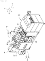
- Fig. 1 shows component mounting machine 10.
- Component mounting machine 10 constitutes a device for executing mounting work of mounting components on circuit substrate 12.
- Component mounting machine 10 includes device main body 20, substrate conveyance and holding device 22, component mounting device 24, imaging devices 26, 28, component feeding device 30, bulk component feeding device 32, and control device (refer to Fig. 11 ) 34.
- a circuit board, a substrate having a three-dimensional structure, and the like are raised as circuit substrate 12, and a printed wiring board, a printed circuit board, and the like are raised as a circuit board.
- Device main body 20 is made up of frame section 40 and beam section 42 mounted on frame section 40.
- Substrate conveyance and holding device 22 is disposed at a center of frame section 40 in a front-rear direction thereof and includes conveyance device 50 and clamping device 52.
- Conveyance device 50 constitutes a device for conveying circuit substrate 12
- clamping device 52 constitutes a device for holding circuit substrate 12.
- substrate conveyance and holding device22 not only conveys circuit substrate 12 but also fixedly holds circuit substrate 12 in a predetermined position.
- the conveyance direction of circuit substrate 12 is referred to as an X direction
- a horizontal direction orthogonal to the conveyance or X direction is referred to a Y direction
- a vertical direction is referred to as a Z direction. That is,the X direction constitutes a width direction of component mounting machine 10, and the Y direction constitutes the front-rear direction thereof.
- Component mounting device 24 is disposed in beam section 42 and includes two work heads 60, 62 and work head moving device 64.
- work heads 60, 62 has suction nozzle (refer to Fig. 2 ) 66 and holds a component using suction nozzle 66.
- working head moving device 64 includes X-direction moving device 68, Y-direction moving device70, and Z-direction moving devices 72. Then, two working heads 60, 62 are caused to move together to an arbitrary position over frame section 40 by X-direction moving device 68 and Y-direction moving device 70. As shown in Fig.
- work heads 60, 62 are detachably attached to sliders 74, 76, respectively, and Z-direction moving devices 72 move individually respective sliders 74, 76 in an up-down direction. That is, working heads 60, 62 are caused to move individually in the up-down direction by respective Z-direction moving devices 72.
- Imaging device 26 is attached to slider 74 in such a state that imaging device 26 is directed downwards and is caused to move in the X direction, Y direction, and Z direction together with working head 60. As a result, imaging device 26 images an arbitrary position over frame section 40. As shown in Fig. 1 , imaging device 28 is disposed between substrate conveyance and holding device 22 and component feeding device 30 over frame section 40 in such a state that imaging device 28 is directed upwards. As a result, imaging device 28 images components held by suction nozzles 66 of work heads 60, 62.
- Component feeding device 30 is disposed at one end portion of frame section 40 in the front-rear direction thereof.
- Component feeding device 30 includes tray-type component feeding device 78 and feeder-type component feeding device (not shown).
- Tray-type component feeding device 78 constitutes a device for supplying components which are rested on a tray.
- Feeder-type component feeding device constitutes a device for supply components by tape feeders (not shown) and stick feeders (not shown).
- Bulk component feeding device 32 is disposed at the other end portion of frame section 40 in the front-rear direction thereof.
- Bulk component feeding device 32 constitutes a device for aligning multiple components, which are scattered in bulk, to have a proper orientation for supply and then supplying the components in the aligned state. That is, bulk component feeding device 32 constitutes the device for aligning multiple components with arbitrary postures to have a predetermined posture for supply, and then supplying the components with the predetermined posture.
- the configuration of bulk component feeding device 32 will be described in detail.
- components supplied by component feeding device 30 and bulk component feeding device 32 are variant components, and more specifically, components supplied by these component feeding devices are, for example, electronic circuit components, solar cell constituent components, power module constituent components, and the like.
- Such electronic circuit components include a component with leads, a component without leads, and the like.
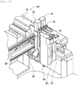
- bulk component feeding device 32 includes main body 80, component supply units 82, imaging device 84, and component delivery device 86.
- Component supply unit 82 includes component supplier 88, component scattering device (refer to Fig. 4 ) 90, and component return device (refer to Fig 4 ) 92, and component supplier 88, component scattering device 90, and component return device 92 are integrated into component supply unit 80.
- Component supply unit 82 is detachably assembled to base 96 of main body 80, and bulk component feeding device 32 has five component supply units 82 which are aligned in a row in the X direction.
- component supplier 88 has a rectangular parallelepiped box shape and is disposed in such a manner as to extend in the Y direction as shown in Figs. 4 and 5 .
- the Y direction is referred to as a front-rear direction of component supplier 88, and in component supply unit 82, a direction towards an end where component return device 92 is disposed is referred to as a front, while a direction towards an end where component supplier 88 is disposed is referred to as a rear.
- Component supplier 88 is opened at an upper surface and a front surface, and an opening in the upper surface constitutes a component supply port 97, while an opening in the front surface constitutes a component discharge port 98.
- an inclined plate 104 is disposed below supply port 97. Inclined plate 104 is disposed in such a manner as to be inclined downwards from a rear end face of component supplier 88 towards a center thereof.
- a conveyor device 106 is disposed at a front side of inclined plate 104.
- Conveyor device 106 is disposed in such a manner as to be inclined upwards from a front end portion of inclined plate 104 towards the front of component supplier 88.
- Conveyor belt 112 of conveyor device 106 turns counterclockwise as seen in Fig. 5 . That is, a conveyance direction of components by conveyor device 106 is an obliquely upward direction starting from the front end portion of inclined plate 104 towards the front.
- multiple protruding sections 115 are formed on a front surface, that is, a conveyance surface of conveyor belt 112 in such a manner as to extend in a width direction of conveyor belt 112.
- Multiple protruding sections 115 are formed at constant intervals in the turning direction of conveyor belt 112, and the interval is made longer than a lengthwise direction of a component supplied by component supplier 88.
- Inclined plate 126 is disposed below a front end portion of conveyor device 106. Inclined plate 126 is disposed to extend from a front end face of component supplier 88 towards below conveyor device 106, and a rear end portion thereof is inclined downwards. Further, inclined plate 128 is also disposed below inclined plate 126. Inclined plate 128 is inclined downwards from a central portion of conveyor device 106 towards discharge port 98 of component supplier 88 in such a manner that a front end portion thereof is positioned lower or downwards.
- a pair of side frame sections 130 are assembled to base 96.
- a pair of side frame sections 130 are erected so as to face parallel to each other while extending in the Y direction.
- a distance defined between the pair of side frame sections 130 is made slightly greater than a widthwise dimension of component supplier 88, so that component supplier 88 is removably installed between the pair of side frame sections 130.
- Component scattering device 90 includes component support member 150 and component support member moving device 152.
- Component support member 150 is made up of stage 156 and a pair of side wall sections 158.
- stage 156 has a long plate-like shape and is disposed in such a manner as to extend forwards from below component supplier 88 installed between a pair of side frame sections 130.
- an upper surface of stage 156 is generally horizontal and is disposed in such a manner as to define a slight clearance between a front end portion of inclined plate 128 of component supplier 88 and itself, as shown in Fig. 5 .
- a pair of side wall sections 158 are fixed to respective longitudinal side sections of stage 156 in such a manner as to be erected therefrom, and respective upper ends of side wall sections 158 extend further upwards than the upper surface of stage 156.
- Component support member moving device 152 slides component support member 150 in the Y direction as a result of the operation of air cylinder (refer to Fig. 11 ) 166. As this occurs, component support member 150 moves between a retracted state (refer to Fig. 6 ) in which component support member 150 is retracted underneath component supplier 88 and an exposed state (refer to Fig. 5 ) in which component support member 150 is exposed from underneath component supplier 88.
- component return device 92 includes component storage container 180 and container swing device 181.
- component storage container 180 has a box-like shape, and a bottom surface thereof is curved into an arc shape in an end view.
- Component storage container 180 is held in a swingable manner at a front end portion of stage 156 of component support member 150 and swings as a result of the operation of container swing device 181. As this occurs, component storage container 180 swings between a storing posture (refer to Fig. 7 ) in which an opening thereof is directed upwards and a return posture (refer to Fig. 8 ) in which the opening is directed towards the upper surface of stage 156 of component support member 150.
- imaging device 84 includes camera 290 and camera moving device 292.
- Camera moving device 292 includes guide rail 296 and slider 298.
- Guide rail 296 is fixed to main body 80 in such a manner as to extend in a widthwise direction (the X direction) of bulk component feeding device 32 above component supplier 88.
- Slider 298 is attached to guide rail 296 in such a manner as to slide thereon and slides to an arbitrary position as a result of the operation of electromagnetic motor (refer to Fig. 11 ) 299.
- camera 290 is mounted on slider 298 in such a state that camera 290 is directed downwards.
- component delivery device 86 includes component holding head moving device 300, component holding head 302, and two shuttle devices 304.
- Component holding head moving device 300 includes X-direction moving device 310, Y-direction moving device 312, and Z-direction moving device 314.
- Y-direction moving device 312 includes Y slider 316 which is disposed in such a manner as to extend in the X direction above component supply units 82, and Y slider 316 moves to an arbitrary position in the Y direction as a result of electromagnetic motor (refer to Fig. 11 ) 319 being driven accordingly.
- X-direction moving device 310 includes X slider 320 disposed on a side surface of Y slider 316, and X slider 320 moves to an arbitrary position in the X direction as a result of electromagnetic motor (refer to Fig. 11 ) 321 being driven accordingly.
- Z-direction moving device 314 includes Z slider 322 disposed on a side surface of X slider 320, and Z slider 322 moves to an arbitrary position in the Z direction as a result of electromagnetic motor (refer to Fig. 11 ) 323 being driven accordingly.
- component holding head 302 includes head main body 330, suction nozzle 332, nozzle turning device 334, and nozzle rotation device 335.
- Head main body 330 is formed integrally with Z slider 322.
- Suction nozzle 332 holds a component through suction and is detachably attached to a lower end portion of holder 340.
- Holder 340 is allowed to be bent on support shaft 344, whereby holder 340 is bent upwards through 90 degrees as a result of nozzle turning device 334 operating accordingly.
- suction nozzle 332 which is attached to the lower end portion of holder 340, turns through 90 degrees to be positioned in a turned position.
- suction nozzle 332 turns between a non-turned position and the turned position as a result of nozzle turning device 334 operating accordingly.
- Suction nozzle 332 can, of course, be stopped to be positioned at an angle between the non-turned position and the turned position.
- nozzle rotation device 335 rotates suction nozzle 332 around it own axis.
- two shuttle devices 304 each include component carrier 388 and component carrier moving device 390 and are fixed to main body 80 in such a manner as to be aligned side by side in a lateral direction ahead of component supply units 82.
- Component carrier 388 includes five component receiving members 392 which are arranged side by side in a row in the lateral direction, and components are placed individually in component receiving members 392.
- Bulk component feeding device 32 can supply various types of components, and, hence, various types of component receiving members 392 are prepared so as to receive components of various configurations.
- component receiving member 392 will be described which is configured to receive electric component 410 with leads as shown in Fig. 10 , as an electronic circuit component supplied by bulk component feeding device 32.
- Lead component 410 is made up of component main body 412 having a block-like shape and two leads 414 which project from a bottom surface of component main body 412.
- Component receiving member 392 has formed therein component receiving recess section 416 having a shape corresponding to the configuration of lead component 410.
- Component receiving recess section 416 constitutes a recess section having a step-like shape, and is made up of main body receiving recess section 418, which is opened in an upper surface of component receiving member 392, and lead receiving recess section 420 which is opened in a bottom surface of main body receiving recess section 418.
- lead component 410 is inserted into an interior of component receiving recess section 416 with leads 414 adopting a posture in which they are directed downwards.
- lead component 410 is placed in the interior of component receiving recess section 416 with leads 414 inserted in lead receiving recess section 420 and component main body 412 inserted in main body receiving recess section 418.
- Component carrier moving device 390 is a plate-like longitudinal member and is disposed at a front side of component supply unit 82 in such a manner as to extend in the front-rear direction, as shown in Fig. 3 .
- Component carrier 388 is disposed on an upper surface of component carrier moving device 390 in such a manner as to slide in the front-rear direction, whereby component carrier 388 slides to an arbitrary position in the front-rear direction as a result of electromagnetic motor (refer to Fig. 11 ) 430 being driven accordingly.
- component carrier 388 slides in a direction in which component carrier 388 moves close to component supply unit 82, component carrier 388 slides to a component receiving position which is situated within a moving range of component holding head 302 within which component holding head 302 is moved by component holding head moving device 300.
- component carrier 388 slides away from component supply unit 82, component carrier 388 slides to a component supply position which is situated within a moving range of working heads 60, 62 within which working heads 60, 62 are moved by work head moving device 64.
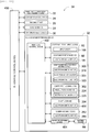
- control device 34 includes integrated control device 450, multiple individual control devices (only one control device is shown in Fig. 1 ) 452, and image processing device 454.
- Integrated control device 450 is made up mainly of a computer and is connected to substrate conveyance and holding device 22, component mounting device 24, imaging device 26, imaging device 28, component feeding device 30, and bulk component feeding device 32.
- integrated control device 450 supervises and control substrate conveyance and holding device 22, component mounting device 24, imaging device 26, imaging device 28, component feeding device 30, and bulk component feeding device 32.
- control devices 452 are each made up mainly of a computer and are provided separately for substrate conveyance and holding device 22, component mounting device 24, imaging device 26, imaging device 28, component feeding device 30, and bulk component feeding device 32 (in the figure, only individual control device 452 for bulk component feeding device 32 is shown).
- Individual control device 452 for bulk component feeding device 32 is connected to component scattering devices 90, component return devices 92, camera moving device 292, component holding head moving device 300, component holding head 302, and shuttle devices 304. As a result, individual control device 452 for bulk component feeding device 32 controls component scattering devices 90, component return devices 92, camera moving device 292, component holding head moving device 300, component holding head 302, and shuttle devices 304.
- Image processing device 454 is connected to imaging device 84 for processing captured image data that is captured by imaging device 84.
- Image processing device 454 is connected to individual control device 452 for bulk component feeding device 32. As a result, individual control device 452 for bulk component feeding device 32 acquires captured image data that is captured by imaging device 84.
- component mounting machine 10 performs mounting work of mounting components on circuit substrate 12 held by substrate conveyance and holding device 22. Specifically, circuit substrate 12 is conveyed to a working position and is fixedly held by clamping device 52 in the working position. Next, imaging device 26 moves to a position lying above circuit substrate 12 and images circuit substrate 12. As a result, information on an error in holding position of circuit substrate 12 is obtained.
- Component feeding device 30 or bulk component feeding device 32 supplies components in a predetermined supply position. A component supply operation by bulk component feeding device 32 will be described in detail later. Then, either of working heads 60, 62 moves to a position lying above the component supply position and holds a component by suction nozzle 66 thereof through suction.
- working head 60 or 62 that holds the component moves to a position lying above imaging device 28, whereby the component held by suction nozzle 66 is imaged by imaging device 28.
- imaging device 28 As a result, information on an error in holding position of the component is obtained.
- working head 60 or 62 that holds the component moves to a position lying above circuit substrate 12 and mounts the component held thereby on circuit substrate 12 by correcting the error in holding position of circuit substrate 12 and the error in holding position of the component.
- the operator supplies lead components 410 into bulk component feeding device 32 from supply ports 97 of component suppliers 88, and lead components 410 so supplied are supplied while being placed on component receiving members 392 of component carriers 388 as a result operation of component supply units 82 and component delivery device 86.
- component support member 150 is moved to lie below component supplier 88 as a result of operation of component support member moving device 152, whereby component support member 150 is pulled in the retracted state (refer to Fig. 6 ).
- component storage container 180 disposed at the front end of component support member 150 is situated at the front of component supplier 88, adopting a posture (a storing posture) in which the opening of component storage container 180 is directed upwards.
- Lead components 410 supplied from supply port 97 of component supplier 88 fall on inclined plate 104 of component supplier 88 and roll down to a front lower end of inclined plate 104. As this occurs, lead components 410, which have rolled down to the front lower end of inclined plate 104, are accumulated between the front lower end of inclined plate 104 and a rear lower end of conveyor device 106. Then, as a result of conveyor device 106 being activated to operate, conveyor belt 112 of conveyor device 106 turns counterclockwise as seen in Fig. 6 .
- lead components 410 which have been so conveyed by conveyor belt 112, fall on inclined plate 126 from a front upper end of conveyor device 106.
- Lead components 410 which have so fallen on inclined plate 126, roll down to the rear on inclined plate 126 to fall on inclined plate 128.
- Lead components 410, which have so fallen on inclined plate 128, roll down to the front and are then discharged from discharge port 98 at the front side of component supplier 88.
- component support member 150 moves to the front from the retracted state as a result of operation of component support member moving device 152.
- container swing device 181 of component return device 92 is activated to operate at a timing at which component support member 150 moves a predetermined amount from the retracted state to the front towards the exposed state, whereby component storage container 180 swings.
- the posture of component storage container 180 changes forcibly from the posture in which the opening is directed upwards (the storing posture) to a posture in which the opening is directed towards stage 156 (a returning posture).
- lead components 410 stored in component storage container 180 are discarded forcibly onto stage 156.
- lead components 410, which have been so discarded onto stage 156 from component storage container 180 are then scattered on stage 156.
- the swing action of the component storage container is set so as to be completed before component support member 150 is completely exposed so as not to extend a cycle time.
- lead components 410 are scattered from component supplier 88 onto stage 156 of component support member 150 by following the procedure that has been described heretofore, camera 290 of imaging device 84 moves to a position lying above component support member 150, as a result of operation of camera moving device 292, and images lead components 410. Then, based on the captured image data, multiple lead components 410 scattered on the upper surface of component support member 150 are divided into lead components that can be picked up by suction nozzle 332, and lead components that cannot be picked up by suction nozzle 332.
- the lead component that can be picked up by suction nozzle 332 is referred to as a pickup target component, while the lead component that cannot be picked up by suction nozzle 332 is referred to as a non-pickup target component.
- lead component 410 an upwardly directed surface of which constitutes an irregular surface or the like which makes it difficult for lead component 410 to be picked up
- lead component 410 which is partly covered by another lead component 410
- lead component 410 which lies too close to side wall section 158 to be picked up, and the like
- pieces of information about lead components 410on are acquired based on the captured image data for lead components 410 classified into pickup target components.
- component holding head 302 moves to a position lying above the pickup target component based on the acquired information on the pickup target components, and as a result of operation of component holding head moving device 300, the relevant pickup target component is picked up and held through suction by suction nozzle 332.
- suction nozzle 332 is situated in the non-turned position.
- component holding head 302 moves to a position lying above component carrier 388 after lead component 410 has been held by suction nozzle 332.
- component carrier 388 moves to the component receiving position as a result of operation of component carrier moving device390.
- suction nozzle 332 is turned to the turned position.
- Suction nozzle 332 turns so that leads 414 of lead component 410 held by suction nozzle 332 in the turned position are directed downwards in the vertical direction as a result of operation of nozzle rotation device 335.
- lead component 410 When component holding head 302 moves to the position lying above component carrier 388, lead component 410, whose leads 414 are directed downwards in the vertical direction, is inserted into component receiving recess section 416 of component receiving member 392. As a result, as shown in Fig. 10 , lead component 410 is placed in component receiving member 392 with leads 414 kept directed downwards in the vertical direction.
- component carrier 388 moves to the component supply position as a result of operation of component carrier moving device 390. Since component carrier 388, which has so moved to the component supply position, is then situated within the moving range of working heads 60, 62, in bulk component feeding device 32, lead component 410 is supplied to component mounting machine 10 in the component supply position. In this way, in bulk component feeding device 32, lead components 410 are supplied with leads 414 directed to face downwards and upper surfaces opposite to bottom surfaces to which leads 414 are connected directed to face upwards. Due to this, suction nozzles 66 of work heads 60, 62 can hold lead components 410 properly.
- lead components 410 left unpicked on stage 156 are recovered into component storage container 180. Then, lead components 410, which have been recovered into component storage container 180, are scattered again on stage 156 in such a manner that lead components 410 adopt different postures, whereby picking up of lead components 410 from stage 156 is resumed.
- component support member 150 moves towards the retracted position underneath component carrier 88 as a result of operation of component support member moving device 152. That is, component support member 150 moves from the exposed state (refer to Fig. 5 ) towards the retracted state (refer to Fig. 6 ). As this occurs, component storage container 180, which is disposed at the front end portion of component support member 150, is adopting the posture (a recovery posture) in which the opening is directed upwards.
- lead components 410 on stage 156 of component support member 150 are held back by a front end portion of inclined plate 128 of component carrier 88.
- component support member 150 is then in the retracted state as shown in Fig. 6 . Due to this, component support member 150 moves from the retracted state to the front as a result of operation of component support member moving device 152. Then, container swing device 181 of component return device 92 is activated to operate at a timing at which component support member 150 moves a predetermined amount from the retracted state to the front towards the exposed state, whereby component storage container 180 swings. As a result, the posture of component storage container 180 changes forcibly from the posture in which the opening is directed upwards (the storing posture) to a posture in which the opening is directed towards stage 156 (a returning posture).
- lead components 410 stored in component storage container 180 are discarded forcibly onto stage 156.
- lead components 410, which have been so discarded onto stage 156 from component storage container 180 are then scattered on stage 156. That is, lead components 410 recovered into component storage container 180 are replenished onto stage 156.
- the postures of lead components 410 so replenished are changed, enabling lead components 410 to be picked up again from the upper surface of stage 156.
- lead components 410 are repeatedly stored from stage 156 into component storage container 180 and lead components 410 are repeatedly replenished from component storage container 180 onto stage 156, the number of lead components 410 scattered on stage 156 is reduced. Thus, when the number of lead components 410 scattered on stage 156 is reduced, lead components 410 are replenished from component supplier 88.
- stage 156 is imaged by camera 290 before lead components 410 are stored from stage 156 into component storage container 180. Then, in the area of stage 156 on which lead components 410 are scattered, an area of portions where lead components 410 are not placed is calculated based on captured image data. That is, an area of portions where stage 156 is exposed (hereinafter, referred to as an "exposed area") is calculated. Specifically speaking, for example, when stage 156 is white color while lead components 410 are black color, the portions recognized as white are extracted based on the captured image data acquired by camera 290, and an area of the portions so extracted is calculated as the exposed area.
- Stage 156 is imaged by camera 290 before lead components 410 are scattered on stage 156, that is, in such a state that nothing is placed on stage 156. Then, an area of stage 156 (hereinafter, referred to as a "stage area”) is calculated based on the acquired captured image data. That is, for example, when stage 156 is white color, white portions are extracted based on the captured image data, and an area of the portions so extracted is calculated as the stage area.
- an area occupied by lead components 410 scattered on stage 156 (hereinafter, referred to as a "component occupation area”) is calculated by subtracting the exposed area from the stage area.
- a ratio of an area occupied by lead components 410 to a total area of stage 156, that is, an occupation ratio of stage 156 by lead components 410 (hereinafter, referred to as a "component occupation ratio) is calculated by calculating a ratio of the component occupation area to the stage area.
- a higher component occupation ratio denotes that the number of lead components 410 scattered on stage 156 becomes greater, while a lower occupation ratio denotes that the number of lead components 410 scattered on stage 156 becomes smaller.
- the component occupation ratio can be used as an index value for estimating the number of lead components 410 scattered on stage 156.
- lead components 410 are supplied onto stage 156 from component supplier 88 while stage 156 is moving from the exposed state towards the retracted state.
- lead components 410 supplied onto stage 156 from component supplier 88 and lead components 410 having been left on stage 156 since before lead components 410 are supplied from component supplier 88 are stored in component storage container 180.
- lead components 410 stores in component storage container 180 are then scattered on stage 156 according to the procedure described above.
- lead components 410 are replenished from component supplier 88 at that timing, whereby lead components 410 can continue to be picked up from stage 156.
- Lead components 410 having remained on stage 156 and components supplied from component supplier 88 are once stored in component storage container 180, and then, the components so stored in component storage container 180 are scattered on the stage again.
- the components that are replenished onto stage 156 include the components that have been left on stage 156 since before the components are stored in component storage container 180.
- Component supplier 88 and component storage container 180 function as a replenishing device.
- a component occupation ratio of lead components 410a of a small size becomes threshold A or smaller
- a relatively large clearance is defined between adjacent lead components 410a. Due to this, when the component occupation ratio of lead components 410a of a small size becomes threshold A or smaller, even though lead components 410a are replenished from component supplier 88, there still remains room where lead components 410a replenished newly can be scattered on stage 156, whereby lead components 410a hardly overlap one another.
- lead components 410b overlap one another with ease, while other lead components 410 overlap one another only with great difficulty.
- lead components 410 overlap one another only with great difficulty.
- lead components 410 do not overlap one another with great difficulty.
- lead components of different sizes can also be considered to be lead components of different shapes.
- thresholds are set for types of lead components 410.
- threshold A1 set for lead component 410b of a large size is set smaller than threshold A2 set for lead component 410a of a small size. That is, with lead components 410a of a large size scattered on stage 156, lead components 410b of a large size are replenished from component supplier 88 in such a state that the number of components remaining on stage 156 is reduced compared with lead components 410a of a small size.
- threshold A3 set for lead component 410 of a shape making it overlap another lead component 410 with ease is set smaller than threshold A4 set for lead component 410 of a shape making it overlap another lead component 410 only with great difficulty. That is, when lead components 410 of a shape making them overlap one another with ease are scattered on stage 156, lead components 410 are replenished from component supplier 88 in such a state that the number of components remaining on stage 156 is reduced compared with lead components 410 of a shape making them overlap one another only with great difficulty. Lead components can be restrained from overlapping one another when the components are replenished from component supplier 88 by setting the thresholds for the types of lead components 410 in the way described above.
- component supplier 88 replenishes lead components 410 onto stage 156 as a result of conveyor belt 112 turning accordingly, and as this occurs, conveyor belt 112 turns, for example, a distance corresponding to a dimension defined between two adjacent protruding sections 115 of conveyor belt 112. As a result, lead components 410 staying between two adjacent protruding sections 115 are supplied onto stage 156 from component supplier 88.
- lead components 410 of a shape facilitating overlapping thereof tend to overlap one another with ease between two adjacent protruding sections 115, a relatively large number of lead components 410 fall to be placed therebetween, and such a large number of lead components 410 are supplied from component supplier 88 onto stage 156.
- lead components 410 of a shape making them hardly overlap each other tend to overlap each other only with great difficulty between two adjacent protruding sections 115. only a relatively small number of lead components 410 are allowed to fall to be placed therebetween, and such a small number of lead components 410 are supplied from component supplier 88 onto stage 156.
- a turning amount of conveyor belt 112 for replenishment of lead components 410a of a small size is set at a distance corresponding to the dimension defined between two adjacent protruding sections 115 (hereinafter, referred to as a "set distance") in individual control device 452 or integrated control device 450.
- a turning amount of conveyor belt 112 for replenishment of lead components 410 of a large size is set at a distance five times greater than the set distance.
- the numbers of components replenished from component supplier 88 onto stage 156 can be made the same in general irrespective of the types of components replenished by setting the turning amounts of conveyor belt 112 according to the types of the components in the way described above. As a result, an appropriate amount of components can be scattered on stage 156 after the components have been replenished from component supplier 88 onto stage 156. Further, the turning amount of the conveyor belt does not have to be limited to a multiple of an integer of the set distance.
- the number of components scattered on stage 156 can be adjusted appropriately so as to ensure an appropriate component supply by setting the threshold for use in specifying the timing at which components are replenished from component supplier 88 and the turning amounts of conveyor belt 112 for replenishment of components in accordance with the types of components to be replenished.
- five component supply units 82 are provided as described above.
- one stage is associated with on component supplier 88, and components are supplied from component supplier 88 which is associated with one stage.
- an amount of components on stage 156 can be adjusted for each of the five component supply units 82. That is, in the case that the five component supply units 82 are each provided with different types of components, thresholds for use in specifying timings at which the different types of components are replenished from component suppliers 88 and turning amounts of conveyor belts 112 for replenishment of the different types of components come to differ from stage 156 to stage 156. As a result, an amount of components scattered on stage 156 is adjusted for each of the five component supply units 82.
- the amount of components on stage 156 can be adjusted according to the amount of components supplied from each of the five component supply units 82, whereby bulk component feeding device 32 can supply various types of components in a well-balanced manner. That is, components can be supplied accurately in accordance with a required component supply speed.
- the thresholds for use in specifying the timings at which the different types of components are replenished and the turning amounts of conveyor belts 112 for replenishment of the different types of components differ from stage 156 to stage 156, the specific types of components can be replenished from respective component suppliers 88 onto respective stages 156 at an arbitrary timing.
- a timing at which conveyor belt 112 starts operating for replenishment of components and a timing at which conveyor belt 112 in question stops operating can be adopted as the arbitrary timing.
- the component replenishing timing can be a timing based on the number of times of replenishment of components from conveyor belt 112 per unit time.
- bulk component feeding device 32 constitutes an example of a component feeding device.
- Component supplier 88 constitutes an example of a replenishing device.
- Stage 156 constitutes an example of a stage.
- Component storing container 180 constitutes an example of the replenishing device.
- Individual control device 452 constitutes an example of a control device.
- the amount of components supplied onto stage 156 is adjusted by setting the threshold for use in specifying the timing at which components are replenished from component supplier 88 and the turning amount of conveyor belt 112 for replenishment of components in accordance with the types of components to be replenished.
- the amount of components supplied onto stage 156 may be adjusted by setting at least one of the threshold and the turning amount of conveyor belt 112 in accordance with the types of components to be replenished.
- one stage is associated with one component supplier
- two stages may be associated with three component suppliers.
- components are supplied from two component suppliers associated with a first stage, and components are supplied from a remaining component supplier associated with a second stage.
- the number of components replenished from component supplier 88 may be adjusted by setting an operation time of conveyor belt 112 in accordance with the types of components to be replenished.
- the number of components replenished from component supplier 88 may be adjusted by setting the number of times of supply of components from the bucket in accordance with the types of components to be replenished.
- the number of components scattered on stage 156 may be used. Specifically speaking, for example, outlines of components having various postures may be distinguished from one another based on the captured image data, so that the number of components scattered on stage 156 is calculated based on the distinguished outlines. In this case, when the number of components so calculated becomes a threshold or smaller, components are replenished from component supplier 88 onto stage 156.
- the total components occupation area is calculated by subtracting the exposed area from the stage area
- the total components occupation area may be calculated based on the captured image data.
- stage 156 is white or bright color
- lead components 410 are black or dark color
- portions recognized as black or dark may be extracted based on the captured image data, so that an area of the portions so extracted is calculated as a component occupation area.
- the invention can be applied to various types of components. Roughly speaking, the invention can be applied to profile components, and specifically speaking, the invention can be applied to, for example, solar cell constituent components, power module constituent components, electronic circuit components with no lead, and the like.
Landscapes
- Engineering & Computer Science (AREA)
- Manufacturing & Machinery (AREA)
- Microelectronics & Electronic Packaging (AREA)
- Mechanical Engineering (AREA)
- Operations Research (AREA)
- Supply And Installment Of Electrical Components (AREA)
- Feeding Of Articles To Conveyors (AREA)
Abstract
Description
- The invention relates to a component feeding device or the like which includes a replenishing device for replenishing components and a stage on which components replenished from the replenishing device are scattered.
- As described in a patent literature raised below as a reference, some component feeding devices supply components in such a state that components are scattered on a stage.
- Patent Literature 1:
JP-A-2010-228819 - The above mentioned patent literature describes the components being supplied on a single stage but does not describe that of being supplied on multiple stages. Then, a technical problem that the invention is to solve is how to supply components on each of multiple stages in a preferred manner.
- With a view to solving the problem, according to the description of the invention, there is disclosed a component feeding device including multiple component replenishing devices configured to replenish with components having different shapes, multiple stages on which the components replenished from the multiple replenishing devices are scattered, and a control section configured to cause the multiple replenishing devices to replenish the components to the respective stages at an arbitrary timing.
- With a view to solving the problem, according to the description, there is disclosed a component feeding method for supplying components, having different shapes and being respectively replenished onto multiple stages from multiple replenishing devices, to a component mounting device with the components being respectively scattered on the multiple stages, wherein amounts of the components can be respectively changed for each of the multiple stages.
- According to the disclosure, the components can be replenished from the multiple replenishing devices onto the respective stages at the arbitrary timings. Also, according to the disclosure, the amounts of components replenished from the replenishing devices onto the respective stages can be changed for each of the multiple stages.
-
- [
Fig. 1] Fig. 1 is a perspective view showing a component mounting machine. - [
Fig. 2] Fig. 2 is a perspective view showing a component mounting device of the component mounting machine. - [
Fig. 3] Fig. 3 is a perspective view showing a bulk component feeding device. - [
Fig. 4] Fig. 4 is a perspective view showing a component supply unit. - [
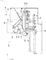
Fig. 5] Fig. 5 is a see-through view showing the component supply unit. - [
Fig. 6] Fig. 6 is a see-through view showing the component supply unit. - [
Fig. 7] Fig. 7 is a perspective view showing a component scattering device. - [
Fig. 8] Fig. 8 is a perspective view showing the component scattering device. - [
Fig. 9] Fig. 9 is a perspective view showing a component holding head. - [
Fig. 10] Fig. 10 is a diagram showing a component receiving member with a lead component stored properly therein. - [
Fig. 11] Fig. 11 is a block diagram showing a control device of the component mounting machine. - [
Fig. 12] Fig. 12 is a view showing a stage on which lead components of small dimensions are scattered. - [
Fig. 13] Fig. 13 is a view showing a stage on which lead components of great dimensions are scattered. - [
Fig. 14] Fig. 14 is a view showing a portion of a conveyor belt where lead components of small dimensions are laid out between two adjacent protruding sections. - [
Fig. 15] Fig. 15 is a view showing a portion of the conveyor belt where lead components of great dimensions are laid out between two adjacent protruding sections. - Hereinafter, with referring to drawings, an embodiment of the invention will be described as exemplary embodiments of the present invention.
-
Fig. 1 showscomponent mounting machine 10.Component mounting machine 10 constitutes a device for executing mounting work of mounting components oncircuit substrate 12.Component mounting machine 10 includes devicemain body 20, substrate conveyance andholding device 22,component mounting device 24,imaging devices component feeding device 30, bulkcomponent feeding device 32, and control device (refer toFig. 11 ) 34. A circuit board, a substrate having a three-dimensional structure, and the like are raised ascircuit substrate 12, and a printed wiring board, a printed circuit board, and the like are raised as a circuit board. - Device
main body 20 is made up offrame section 40 andbeam section 42 mounted onframe section 40. Substrate conveyance andholding device 22 is disposed at a center offrame section 40 in a front-rear direction thereof and includesconveyance device 50 andclamping device 52.Conveyance device 50 constitutes a device for conveyingcircuit substrate 12, andclamping device 52 constitutes a device forholding circuit substrate 12. As a result, substrate conveyance and holding device22 not only conveyscircuit substrate 12 but also fixedly holdscircuit substrate 12 in a predetermined position. In the following description, the conveyance direction ofcircuit substrate 12 is referred to as an X direction, a horizontal direction orthogonal to the conveyance or X direction is referred to a Y direction, and a vertical direction is referred to as a Z direction. That is,the X direction constitutes a width direction ofcomponent mounting machine 10, and the Y direction constitutes the front-rear direction thereof. -
Component mounting device 24 is disposed inbeam section 42 and includes twowork heads head moving device 64. Each ofwork heads Fig. 2 ) 66 and holds a component usingsuction nozzle 66. Further, workinghead moving device 64 includesX-direction moving device 68, Y-direction moving device70, and Z-direction moving devices 72. Then, twoworking heads frame section 40 byX-direction moving device 68 and Y-direction moving device 70. As shown inFig. 2 ,work heads sliders direction moving devices 72 move individuallyrespective sliders heads direction moving devices 72. -
Imaging device 26 is attached toslider 74 in such a state thatimaging device 26 is directed downwards and is caused to move in the X direction, Y direction, and Z direction together with workinghead 60. As a result,imaging device 26 images an arbitrary position overframe section 40. As shown inFig. 1 ,imaging device 28 is disposed between substrate conveyance andholding device 22 andcomponent feeding device 30 overframe section 40 in such a state thatimaging device 28 is directed upwards. As a result,imaging device 28 images components held bysuction nozzles 66 ofwork heads -
Component feeding device 30 is disposed at one end portion offrame section 40 in the front-rear direction thereof.Component feeding device 30 includes tray-typecomponent feeding device 78 and feeder-type component feeding device (not shown). Tray-typecomponent feeding device 78 constitutes a device for supplying components which are rested on a tray. Feeder-type component feeding device constitutes a device for supply components by tape feeders (not shown) and stick feeders (not shown). - Bulk
component feeding device 32 is disposed at the other end portion offrame section 40 in the front-rear direction thereof. Bulkcomponent feeding device 32 constitutes a device for aligning multiple components, which are scattered in bulk, to have a proper orientation for supply and then supplying the components in the aligned state. That is, bulkcomponent feeding device 32 constitutes the device for aligning multiple components with arbitrary postures to have a predetermined posture for supply, and then supplying the components with the predetermined posture. Hereinafter, the configuration of bulkcomponent feeding device 32 will be described in detail. In high level, components supplied bycomponent feeding device 30 and bulkcomponent feeding device 32 are variant components, and more specifically, components supplied by these component feeding devices are, for example, electronic circuit components, solar cell constituent components, power module constituent components, and the like. Such electronic circuit components include a component with leads, a component without leads, and the like. - As shown in
Fig. 3 , bulkcomponent feeding device 32 includesmain body 80,component supply units 82,imaging device 84, andcomponent delivery device 86. -
Component supply unit 82 includescomponent supplier 88, component scattering device (refer toFig. 4 ) 90, and component return device (refer toFig 4 ) 92, andcomponent supplier 88,component scattering device 90, andcomponent return device 92 are integrated intocomponent supply unit 80.Component supply unit 82 is detachably assembled to base 96 ofmain body 80, and bulkcomponent feeding device 32 has fivecomponent supply units 82 which are aligned in a row in the X direction. - In general,
component supplier 88 has a rectangular parallelepiped box shape and is disposed in such a manner as to extend in the Y direction as shown inFigs. 4 and5 . The Y direction is referred to as a front-rear direction ofcomponent supplier 88, and incomponent supply unit 82, a direction towards an end wherecomponent return device 92 is disposed is referred to as a front, while a direction towards an end wherecomponent supplier 88 is disposed is referred to as a rear. -
Component supplier 88 is opened at an upper surface and a front surface, and an opening in the upper surface constitutes acomponent supply port 97, while an opening in the front surface constitutes acomponent discharge port 98. Incomponent supplier 88, aninclined plate 104 is disposed belowsupply port 97.Inclined plate 104 is disposed in such a manner as to be inclined downwards from a rear end face ofcomponent supplier 88 towards a center thereof. - As shown in
Fig. 5 , aconveyor device 106 is disposed at a front side ofinclined plate 104.Conveyor device 106 is disposed in such a manner as to be inclined upwards from a front end portion ofinclined plate 104 towards the front ofcomponent supplier 88.Conveyor belt 112 ofconveyor device 106 turns counterclockwise as seen inFig. 5 . That is, a conveyance direction of components byconveyor device 106 is an obliquely upward direction starting from the front end portion ofinclined plate 104 towards the front. In addition, multiple protrudingsections 115 are formed on a front surface, that is, a conveyance surface ofconveyor belt 112 in such a manner as to extend in a width direction ofconveyor belt 112. Multiple protrudingsections 115 are formed at constant intervals in the turning direction ofconveyor belt 112, and the interval is made longer than a lengthwise direction of a component supplied bycomponent supplier 88. -
Inclined plate 126 is disposed below a front end portion ofconveyor device 106.Inclined plate 126 is disposed to extend from a front end face ofcomponent supplier 88 towardsbelow conveyor device 106, and a rear end portion thereof is inclined downwards. Further, inclinedplate 128 is also disposed belowinclined plate 126.Inclined plate 128 is inclined downwards from a central portion ofconveyor device 106 towardsdischarge port 98 ofcomponent supplier 88 in such a manner that a front end portion thereof is positioned lower or downwards. - Additionally, as shown in
Fig. 4 , a pair ofside frame sections 130 are assembled tobase 96. A pair ofside frame sections 130 are erected so as to face parallel to each other while extending in the Y direction. A distance defined between the pair ofside frame sections 130 is made slightly greater than a widthwise dimension ofcomponent supplier 88, so thatcomponent supplier 88 is removably installed between the pair ofside frame sections 130. -
Component scattering device 90 includescomponent support member 150 and component supportmember moving device 152.Component support member 150 is made up ofstage 156 and a pair ofside wall sections 158. In general,stage 156 has a long plate-like shape and is disposed in such a manner as to extend forwards from belowcomponent supplier 88 installed between a pair ofside frame sections 130. Incidentally, an upper surface ofstage 156 is generally horizontal and is disposed in such a manner as to define a slight clearance between a front end portion ofinclined plate 128 ofcomponent supplier 88 and itself, as shown inFig. 5 . As shown inFig. 4 , a pair ofside wall sections 158 are fixed to respective longitudinal side sections ofstage 156 in such a manner as to be erected therefrom, and respective upper ends ofside wall sections 158 extend further upwards than the upper surface ofstage 156. - Component support
member moving device 152 slidescomponent support member 150 in the Y direction as a result of the operation of air cylinder (refer toFig. 11 ) 166. As this occurs,component support member 150 moves between a retracted state (refer toFig. 6 ) in whichcomponent support member 150 is retracted underneathcomponent supplier 88 and an exposed state (refer toFig. 5 ) in whichcomponent support member 150 is exposed from underneathcomponent supplier 88. - As shown in
Fig. 7 ,component return device 92 includescomponent storage container 180 andcontainer swing device 181. In general,component storage container 180 has a box-like shape, and a bottom surface thereof is curved into an arc shape in an end view.Component storage container 180 is held in a swingable manner at a front end portion ofstage 156 ofcomponent support member 150 and swings as a result of the operation ofcontainer swing device 181. As this occurs,component storage container 180 swings between a storing posture (refer toFig. 7 ) in which an opening thereof is directed upwards and a return posture (refer toFig. 8 ) in which the opening is directed towards the upper surface ofstage 156 ofcomponent support member 150. - As shown in
Fig. 3 ,imaging device 84 includescamera 290 andcamera moving device 292.Camera moving device 292 includesguide rail 296 andslider 298.Guide rail 296 is fixed tomain body 80 in such a manner as to extend in a widthwise direction (the X direction) of bulkcomponent feeding device 32 abovecomponent supplier 88.Slider 298 is attached to guiderail 296 in such a manner as to slide thereon and slides to an arbitrary position as a result of the operation of electromagnetic motor (refer toFig. 11 ) 299. In addition,camera 290 is mounted onslider 298 in such a state thatcamera 290 is directed downwards. - As shown in
Fig. 3 ,component delivery device 86 includes component holdinghead moving device 300,component holding head 302, and twoshuttle devices 304. - Component holding
head moving device 300 includesX-direction moving device 310, Y-direction moving device 312, and Z-direction moving device 314. Y-direction moving device 312 includesY slider 316 which is disposed in such a manner as to extend in the X direction abovecomponent supply units 82, andY slider 316 moves to an arbitrary position in the Y direction as a result of electromagnetic motor (refer toFig. 11 ) 319 being driven accordingly.X-direction moving device 310 includesX slider 320 disposed on a side surface ofY slider 316, andX slider 320 moves to an arbitrary position in the X direction as a result of electromagnetic motor (refer toFig. 11 ) 321 being driven accordingly. Z-direction moving device 314 includesZ slider 322 disposed on a side surface ofX slider 320, andZ slider 322 moves to an arbitrary position in the Z direction as a result of electromagnetic motor (refer toFig. 11 ) 323 being driven accordingly. - As shown in
Fig. 9 ,component holding head 302 includes headmain body 330,suction nozzle 332,nozzle turning device 334, andnozzle rotation device 335. Headmain body 330 is formed integrally withZ slider 322.Suction nozzle 332 holds a component through suction and is detachably attached to a lower end portion ofholder 340.Holder 340 is allowed to be bent onsupport shaft 344, wherebyholder 340 is bent upwards through 90 degrees as a result ofnozzle turning device 334 operating accordingly. As a result,suction nozzle 332, which is attached to the lower end portion ofholder 340, turns through 90 degrees to be positioned in a turned position. That is,suction nozzle 332 turns between a non-turned position and the turned position as a result ofnozzle turning device 334 operating accordingly.Suction nozzle 332 can, of course, be stopped to be positioned at an angle between the non-turned position and the turned position. Additionally,nozzle rotation device 335 rotatessuction nozzle 332 around it own axis. - As shown in
Fig. 3 , twoshuttle devices 304 each includecomponent carrier 388 and componentcarrier moving device 390 and are fixed tomain body 80 in such a manner as to be aligned side by side in a lateral direction ahead ofcomponent supply units 82.Component carrier 388 includes fivecomponent receiving members 392 which are arranged side by side in a row in the lateral direction, and components are placed individually incomponent receiving members 392. - Bulk
component feeding device 32 can supply various types of components, and, hence, various types ofcomponent receiving members 392 are prepared so as to receive components of various configurations. Here,component receiving member 392 will be described which is configured to receiveelectric component 410 with leads as shown inFig. 10 , as an electronic circuit component supplied by bulkcomponent feeding device 32.Lead component 410 is made up of componentmain body 412 having a block-like shape and twoleads 414 which project from a bottom surface of componentmain body 412. -
Component receiving member 392 has formed therein component receivingrecess section 416 having a shape corresponding to the configuration oflead component 410. Component receivingrecess section 416 constitutes a recess section having a step-like shape, and is made up of main body receivingrecess section 418, which is opened in an upper surface ofcomponent receiving member 392, and lead receivingrecess section 420 which is opened in a bottom surface of main body receivingrecess section 418. Then,lead component 410 is inserted into an interior of component receivingrecess section 416 withleads 414 adopting a posture in which they are directed downwards. As a result,lead component 410 is placed in the interior of component receivingrecess section 416 withleads 414 inserted in leadreceiving recess section 420 and componentmain body 412 inserted in main body receivingrecess section 418. - Component
carrier moving device 390 is a plate-like longitudinal member and is disposed at a front side ofcomponent supply unit 82 in such a manner as to extend in the front-rear direction, as shown inFig. 3 .Component carrier 388 is disposed on an upper surface of componentcarrier moving device 390 in such a manner as to slide in the front-rear direction, wherebycomponent carrier 388 slides to an arbitrary position in the front-rear direction as a result of electromagnetic motor (refer toFig. 11 ) 430 being driven accordingly. Incidentally, whencomponent carrier 388 slides in a direction in whichcomponent carrier 388 moves close tocomponent supply unit 82,component carrier 388 slides to a component receiving position which is situated within a moving range ofcomponent holding head 302 within whichcomponent holding head 302 is moved by component holdinghead moving device 300. On the other hand, whencomponent carrier 388 slides away fromcomponent supply unit 82,component carrier 388 slides to a component supply position which is situated within a moving range of workingheads head moving device 64. - As shown in
Fig. 11 ,control device 34 includesintegrated control device 450, multiple individual control devices (only one control device is shown inFig. 1 ) 452, andimage processing device 454.Integrated control device 450 is made up mainly of a computer and is connected to substrate conveyance and holdingdevice 22,component mounting device 24,imaging device 26,imaging device 28,component feeding device 30, and bulkcomponent feeding device 32. As a result, integratedcontrol device 450 supervises and control substrate conveyance and holdingdevice 22,component mounting device 24,imaging device 26,imaging device 28,component feeding device 30, and bulkcomponent feeding device 32. Multipleindividual control devices 452 are each made up mainly of a computer and are provided separately for substrate conveyance and holdingdevice 22,component mounting device 24,imaging device 26,imaging device 28,component feeding device 30, and bulk component feeding device 32 (in the figure, onlyindividual control device 452 for bulkcomponent feeding device 32 is shown). -
Individual control device 452 for bulkcomponent feeding device 32 is connected tocomponent scattering devices 90,component return devices 92,camera moving device 292, component holdinghead moving device 300,component holding head 302, andshuttle devices 304. As a result,individual control device 452 for bulkcomponent feeding device 32 controlscomponent scattering devices 90,component return devices 92,camera moving device 292, component holdinghead moving device 300,component holding head 302, andshuttle devices 304.Image processing device 454 is connected toimaging device 84 for processing captured image data that is captured by imagingdevice 84.Image processing device 454 is connected toindividual control device 452 for bulkcomponent feeding device 32. As a result,individual control device 452 for bulkcomponent feeding device 32 acquires captured image data that is captured by imagingdevice 84. - Having the configuration that has been described heretofore,
component mounting machine 10 performs mounting work of mounting components oncircuit substrate 12 held by substrate conveyance and holdingdevice 22. Specifically,circuit substrate 12 is conveyed to a working position and is fixedly held by clampingdevice 52 in the working position. Next,imaging device 26 moves to a position lying abovecircuit substrate 12 andimages circuit substrate 12. As a result, information on an error in holding position ofcircuit substrate 12 is obtained.Component feeding device 30 or bulkcomponent feeding device 32 supplies components in a predetermined supply position. A component supply operation by bulkcomponent feeding device 32 will be described in detail later. Then, either of workingheads suction nozzle 66 thereof through suction. Subsequently, workinghead imaging device 28, whereby the component held bysuction nozzle 66 is imaged by imagingdevice 28. As a result, information on an error in holding position of the component is obtained. Then, workinghead circuit substrate 12 and mounts the component held thereby oncircuit substrate 12 by correcting the error in holding position ofcircuit substrate 12 and the error in holding position of the component. - The operator supplies
lead components 410 into bulkcomponent feeding device 32 fromsupply ports 97 ofcomponent suppliers 88, and leadcomponents 410 so supplied are supplied while being placed oncomponent receiving members 392 ofcomponent carriers 388 as a result operation ofcomponent supply units 82 andcomponent delivery device 86. - To describe this in detail, the operator supplies lead
components 410 fromsupply port 97 in the upper surface ofcomponent supplier 88. At this time,component support member 150 is moved to lie belowcomponent supplier 88 as a result of operation of component supportmember moving device 152, wherebycomponent support member 150 is pulled in the retracted state (refer toFig. 6 ). Withcomponent support member 150 staying in the retracted state,component storage container 180 disposed at the front end ofcomponent support member 150 is situated at the front ofcomponent supplier 88, adopting a posture (a storing posture) in which the opening ofcomponent storage container 180 is directed upwards. - Lead
components 410 supplied fromsupply port 97 ofcomponent supplier 88 fall oninclined plate 104 ofcomponent supplier 88 and roll down to a front lower end ofinclined plate 104. As this occurs,lead components 410, which have rolled down to the front lower end ofinclined plate 104, are accumulated between the front lower end ofinclined plate 104 and a rear lower end ofconveyor device 106. Then, as a result ofconveyor device 106 being activated to operate,conveyor belt 112 ofconveyor device 106 turns counterclockwise as seen inFig. 6 . At this time, inlead components 410 accumulated betweeninclined plate 104 andconveyor belt 112, a predetermined number oflead components 410 enter between adjacent protrudingsections 115 onconveyor belt 112, whereby multiplelead components 410, which are now staying between adjacent protrudingsections 115, are conveyed obliquely upwards byconveyor belt 112. - Then,
lead components 410, which have been so conveyed byconveyor belt 112, fall oninclined plate 126 from a front upper end ofconveyor device 106. Leadcomponents 410, which have so fallen oninclined plate 126, roll down to the rear oninclined plate 126 to fall oninclined plate 128. Leadcomponents 410, which have so fallen oninclined plate 128, roll down to the front and are then discharged fromdischarge port 98 at the front side ofcomponent supplier 88. - As a result,
lead components 410, which are discharged fromdischarge port 98 ofcomponent supplier 88, are stored in an interior ofcomponent storage container 180. Then, when the predetermined amount oflead components 410 are discharged fromcomponent supplier 88, that is, whenconveyor device 106 operates a certain amount,conveyor device 106 stops. Next,component support member 150 moves to the front from the retracted state as a result of operation of component supportmember moving device 152. - Then,
container swing device 181 ofcomponent return device 92 is activated to operate at a timing at whichcomponent support member 150 moves a predetermined amount from the retracted state to the front towards the exposed state, wherebycomponent storage container 180 swings. As a result, the posture ofcomponent storage container 180 changes forcibly from the posture in which the opening is directed upwards (the storing posture) to a posture in which the opening is directed towards stage 156 (a returning posture). As this occurs,lead components 410 stored incomponent storage container 180 are discarded forcibly ontostage 156. As a result,lead components 410, which have been so discarded ontostage 156 fromcomponent storage container 180, are then scattered onstage 156. In addition, the swing action of the component storage container is set so as to be completed beforecomponent support member 150 is completely exposed so as not to extend a cycle time. - When
lead components 410 are scattered fromcomponent supplier 88 ontostage 156 ofcomponent support member 150 by following the procedure that has been described heretofore,camera 290 ofimaging device 84 moves to a position lying abovecomponent support member 150, as a result of operation ofcamera moving device 292, and images leadcomponents 410. Then, based on the captured image data, multiplelead components 410 scattered on the upper surface ofcomponent support member 150 are divided into lead components that can be picked up bysuction nozzle 332, and lead components that cannot be picked up bysuction nozzle 332. The lead component that can be picked up bysuction nozzle 332 is referred to as a pickup target component, while the lead component that cannot be picked up bysuction nozzle 332 is referred to as a non-pickup target component. - Since a classifying method for classifying components into pickup target components and non-pickup target components has nothing to do with the invention, the method will be described briefly in which lead
component 410 an upwardly directed surface of which constitutes an irregular surface or the like which makes it difficult forlead component 410 to be picked up,lead component 410 which is partly covered by anotherlead component 410,lead component 410 which lies too close toside wall section 158 to be picked up, and the like are classified into non-pickup target components, while remaininglead components 410 are classified into pickup target components. Further, pieces of information about lead components 410on, such as the positions oncomponent support member 150, postures thereof and the like, are acquired based on the captured image data forlead components 410 classified into pickup target components. - Then,
component holding head 302 moves to a position lying above the pickup target component based on the acquired information on the pickup target components, and as a result of operation of component holdinghead moving device 300, the relevant pickup target component is picked up and held through suction bysuction nozzle 332. When the pickup target component is picked up and held through suction bysuction nozzle 332,suction nozzle 332 is situated in the non-turned position. - Next,
component holding head 302 moves to a position lying abovecomponent carrier 388 afterlead component 410 has been held bysuction nozzle 332. As this occurs,component carrier 388 moves to the component receiving position as a result of operation of component carrier moving device390. Whencomponent holding head 302 moves to the position lying abovecomponent carrier 388,suction nozzle 332 is turned to the turned position.Suction nozzle 332 turns so that leads 414 oflead component 410 held bysuction nozzle 332 in the turned position are directed downwards in the vertical direction as a result of operation ofnozzle rotation device 335. - When
component holding head 302 moves to the position lying abovecomponent carrier 388,lead component 410, whose leads 414 are directed downwards in the vertical direction, is inserted into component receivingrecess section 416 ofcomponent receiving member 392. As a result, as shown inFig. 10 ,lead component 410 is placed incomponent receiving member 392 withleads 414 kept directed downwards in the vertical direction. - Then, when
lead component 410 is so placed incomponent receiving member 392,component carrier 388 moves to the component supply position as a result of operation of componentcarrier moving device 390. Sincecomponent carrier 388, which has so moved to the component supply position, is then situated within the moving range of workingheads component feeding device 32,lead component 410 is supplied tocomponent mounting machine 10 in the component supply position. In this way, in bulkcomponent feeding device 32,lead components 410 are supplied withleads 414 directed to face downwards and upper surfaces opposite to bottom surfaces to which leads 414 are connected directed to face upwards. Due to this,suction nozzles 66 of work heads 60, 62 can holdlead components 410 properly. - In bulk
component feeding device 32, as pickup target components are kept scattered onstage 156 ofcomponent support member 150, the scattered pickup target components are repeatedly picked up, and then, the pickup target components so picked up are placed incomponent receiving members 392 accordingly. Then,component carrier 388 includingcomponent receiving members 392 mounted thereon is moved to the component supply position, wherebylead components 410 are supplied as set. However, with no pickup target components scattered onstage 156 ofcomponent support member 150, nolead component 410 cannot be picked up fromstage 156. That is, with alllead components 410 determined as pickup acceptable components having been picked up, leavinglead components 410 determined as pickup unacceptable components orlead components 410 determined to be unavailable for determination onstage 156, nolead component 410 cannot be picked up fromstage 156. - To deal with such a case, in bulk
component feeding device 32,lead components 410 left unpicked onstage 156 are recovered intocomponent storage container 180. Then,lead components 410, which have been recovered intocomponent storage container 180, are scattered again onstage 156 in such a manner that leadcomponents 410 adopt different postures, whereby picking up oflead components 410 fromstage 156 is resumed. - Specifically, when all pickup target components on
stage 156 are picked up,component support member 150 moves towards the retracted position underneathcomponent carrier 88 as a result of operation of component supportmember moving device 152. That is,component support member 150 moves from the exposed state (refer toFig. 5 ) towards the retracted state (refer toFig. 6 ). As this occurs,component storage container 180, which is disposed at the front end portion ofcomponent support member 150, is adopting the posture (a recovery posture) in which the opening is directed upwards. Whencomponent support member 150 moves from the exposed state towards the retracted state,lead components 410 onstage 156 ofcomponent support member 150 are held back by a front end portion ofinclined plate 128 ofcomponent carrier 88. - Further, as shown in
Fig. 6 , whencomponent support member 150 has moved to reach the retracted state,lead components 410 onstage 156 are swept off to fall into an interior ofcomponent storage container 180. As a result,lead components 410 onstage 156 are recovered intocomponent storage container 180. Whenlead components 410 onstage 156 are recovered intocomponent storage container 180 in the way described above,lead components 410 so recovered are replenished ontostage 156. - To describe this in detail, when the recovery of
lead components 410 intocomponent storage container 180 is completed,component support member 150 is then in the retracted state as shown inFig. 6 . Due to this,component support member 150 moves from the retracted state to the front as a result of operation of component supportmember moving device 152. Then,container swing device 181 ofcomponent return device 92 is activated to operate at a timing at whichcomponent support member 150 moves a predetermined amount from the retracted state to the front towards the exposed state, wherebycomponent storage container 180 swings. As a result, the posture ofcomponent storage container 180 changes forcibly from the posture in which the opening is directed upwards (the storing posture) to a posture in which the opening is directed towards stage 156 (a returning posture). - As this occurs,
lead components 410 stored incomponent storage container 180 are discarded forcibly ontostage 156. As a result,lead components 410, which have been so discarded ontostage 156 fromcomponent storage container 180, are then scattered onstage 156. That is,lead components 410 recovered intocomponent storage container 180 are replenished ontostage 156. As a result, the postures oflead components 410 so replenished are changed, enablinglead components 410 to be picked up again from the upper surface ofstage 156. - Further, when
lead components 410 are repeatedly stored fromstage 156 intocomponent storage container 180 andlead components 410 are repeatedly replenished fromcomponent storage container 180 ontostage 156, the number oflead components 410 scattered onstage 156 is reduced. Thus, when the number oflead components 410 scattered onstage 156 is reduced,lead components 410 are replenished fromcomponent supplier 88. - Specifically speaking, in order to replenish
lead components 410 fromcomponent supplier 88, the number oflead components 410 left scattered onstage 156 needs to be recognized. Then, an occupation ratio ofstage 156 bylead components 410 is used as an index value for estimating the number oflead components 410 scattered onstage 156. - To describe this in detail,
stage 156 is imaged bycamera 290 beforelead components 410 are stored fromstage 156 intocomponent storage container 180. Then, in the area ofstage 156 on which leadcomponents 410 are scattered, an area of portions wherelead components 410 are not placed is calculated based on captured image data. That is, an area of portions wherestage 156 is exposed (hereinafter, referred to as an "exposed area") is calculated. Specifically speaking, for example, whenstage 156 is white color whilelead components 410 are black color, the portions recognized as white are extracted based on the captured image data acquired bycamera 290, and an area of the portions so extracted is calculated as the exposed area. -
Stage 156 is imaged bycamera 290 beforelead components 410 are scattered onstage 156, that is, in such a state that nothing is placed onstage 156. Then, an area of stage 156 (hereinafter, referred to as a "stage area") is calculated based on the acquired captured image data. That is, for example, whenstage 156 is white color, white portions are extracted based on the captured image data, and an area of the portions so extracted is calculated as the stage area. - Then, an area occupied by
lead components 410 scattered on stage 156 (hereinafter, referred to as a "component occupation area") is calculated by subtracting the exposed area from the stage area. Next, a ratio of an area occupied bylead components 410 to a total area ofstage 156, that is, an occupation ratio ofstage 156 by lead components 410 (hereinafter, referred to as a "component occupation ratio) is calculated by calculating a ratio of the component occupation area to the stage area. A higher component occupation ratio denotes that the number oflead components 410 scattered onstage 156 becomes greater, while a lower occupation ratio denotes that the number oflead components 410 scattered onstage 156 becomes smaller. As a result, the component occupation ratio can be used as an index value for estimating the number oflead components 410 scattered onstage 156. - As a result, when a calculated component occupation ratio becomes a threshold or smaller, it is estimated that the number of
lead components 410 scattered onstage 156 becomes a predetermined number or smaller, components are replenished ontostage 156 fromcomponent supplier 88. Specifically speaking, when the calculated component occupation ratio becomes the threshold or smaller,component support member 150 moves from the exposed state towards the retracted state as a result of operation of component supportmember moving device 152. As this occurs,lead components 410 are supplied fromcomponent supplier 88 at that timing. Since the supply work of supplyinglead components 410 fromcomponent supplier 88 has already been described before, a detailed description thereof will be omitted here. - That is, when the calculated component occupation ratio becomes the threshold or smaller,
lead components 410 are supplied ontostage 156 fromcomponent supplier 88 whilestage 156 is moving from the exposed state towards the retracted state. As a result,lead components 410 supplied ontostage 156 fromcomponent supplier 88 andlead components 410 having been left onstage 156 since beforelead components 410 are supplied fromcomponent supplier 88 are stored incomponent storage container 180. Then,lead components 410 stores incomponent storage container 180 are then scattered onstage 156 according to the procedure described above. As a result, when the number oflead components 410 remaining onstage 156 is reduced,lead components 410 are replenished fromcomponent supplier 88 at that timing, wherebylead components 410 can continue to be picked up fromstage 156. - Lead
components 410 having remained onstage 156 and components supplied fromcomponent supplier 88 are once stored incomponent storage container 180, and then, the components so stored incomponent storage container 180 are scattered on the stage again. Thus, the components that are replenished ontostage 156 include the components that have been left onstage 156 since before the components are stored incomponent storage container 180.Component supplier 88 andcomponent storage container 180 function as a replenishing device. - As described above, when the component occupation ratio becomes the threshold or smaller,
lead components 410 are supplied fromcomponent supplier 88 ontostage 156, wherebylead components 410 are allowed to continue to be picked up fromstage 156. However, in the event that the threshold is set uniform irrespective of types oflead components 410, there is a possibility that leadcomponents 410 scattered onstage 156 come to overlap one another. - Specifically speaking, for example, as shown in
Fig. 12 , when a component occupation ratio oflead components 410a of a small size becomes threshold A or smaller, a relatively large clearance is defined between adjacentlead components 410a. Due to this, when the component occupation ratio oflead components 410a of a small size becomes threshold A or smaller, even thoughlead components 410a are replenished fromcomponent supplier 88, there still remains room wherelead components 410a replenished newly can be scattered onstage 156, wherebylead components 410a hardly overlap one another. - On the other hand, as shown in
Fig. 13 , when a component occupation ratio oflead components 410b of a large size becomes the threshold A or smaller, there remains almost no clearance among adjacentlead components 410b. As a result, in the case that the component occupation ratio oflead components 410b of a large size becomes threshold A or smaller, whenlead components 410b are replenished fromcomponent supplier 88, there remains no roof forlead components 410b replenished newly to be scattered onstage 156, wherebylead components 410b tend to overlap one another easily. - That is, in the case that the component occupation ratio of
lead components 410b of a large size becomes threshold A or smaller, whenlead components 410b are supplied fromcomponent supplier 88,lead components 410b come to overlap one another onstage 156, increasing the probability that leadcomponents 410b so supplied become non-pickup target components. When the probability that leadcomponents 410b become non-pickup target components is increased in this way, the number of times of performing the recovery work of recovering components intocomponent storage container 180 is increased, reducing the work efficiency. - In addition, depending upon a shape of
lead component 410 in addition to the size oflead component 410, somelead components 410b overlap one another with ease, while otherlead components 410 overlap one another only with great difficulty. As a result, when the component occupation ratio oflead component 410 tending to overlap anotherlead component 410 only with difficulty becomes threshold A or smaller, even thoughlead components 410b are replenished fromcomponent supplier 88,lead components 410 overlap one another only with great difficulty. On the other hand, in the case that the component occupation ratio oflead component 410 tending to overlap anotherlead component 410 with ease becomes threshold A or smaller, whenlead components 410 are replenished fromcomponent supplier 88,lead components 410 come to overlap one another with ease. In other words, lead components of different sizes can also be considered to be lead components of different shapes. - In view of these situations, with bulk
component feeding device 32, thresholds are set for types oflead components 410. For example, threshold A1 set forlead component 410b of a large size is set smaller than threshold A2 set forlead component 410a of a small size. That is, withlead components 410a of a large size scattered onstage 156,lead components 410b of a large size are replenished fromcomponent supplier 88 in such a state that the number of components remaining onstage 156 is reduced compared withlead components 410a of a small size. - In addition, for example, threshold A3 set for
lead component 410 of a shape making it overlap anotherlead component 410 with ease is set smaller than threshold A4 set forlead component 410 of a shape making it overlap anotherlead component 410 only with great difficulty. That is, whenlead components 410 of a shape making them overlap one another with ease are scattered onstage 156,lead components 410 are replenished fromcomponent supplier 88 in such a state that the number of components remaining onstage 156 is reduced compared withlead components 410 of a shape making them overlap one another only with great difficulty. Lead components can be restrained from overlapping one another when the components are replenished fromcomponent supplier 88 by setting the thresholds for the types oflead components 410 in the way described above. - However, since the numbers of components replenished from
component supplier 88 differ according to types oflead components 410 whenlead components 410 are replenished ontostage 156 fromcomponent supplier 88, there is a possibility that an appropriate number oflead components 410 cannot be scattered onstage 156 after replenishment. To describe this in detail,component supplier 88 replenisheslead components 410 ontostage 156 as a result ofconveyor belt 112 turning accordingly, and as this occurs,conveyor belt 112 turns, for example, a distance corresponding to a dimension defined between two adjacent protrudingsections 115 ofconveyor belt 112. As a result,lead components 410 staying between two adjacent protrudingsections 115 are supplied ontostage 156 fromcomponent supplier 88. - Specifically speaking, for example, when
lead components 410a of a small size are supplied from thecomponent supply unit 88, as shown inFig. 14 , since ninelead components 410a are supplied to be placed between two adjacent protrudingsections 115, ninelead components 410a are supplied fromcomponent supplier 88 ontostage 156. On the other hand, whenlead components 410b of a large size are supplied fromcomponent supplier 88, since twolead components 410a are supplied to be placed between two adjacent protrudingsections 115 as shown inFig. 15 , twolead components 410b are supplied fromcomponent supplier 88 ontostage 156. - Additionally, since
lead components 410 of a shape facilitating overlapping thereof tend to overlap one another with ease between two adjacent protrudingsections 115, a relatively large number oflead components 410 fall to be placed therebetween, and such a large number oflead components 410 are supplied fromcomponent supplier 88 ontostage 156. On the other hand, sincelead components 410 of a shape making them hardly overlap each other tend to overlap each other only with great difficulty between two adjacent protrudingsections 115. only a relatively small number oflead components 410 are allowed to fall to be placed therebetween, and such a small number oflead components 410 are supplied fromcomponent supplier 88 ontostage 156. - In this manner, in replenishing
lead components 410 fromcomponent supplier 88, when the turning amount ofconveyor belt 112 is set uniform irrespective of the types of components, the replenishing numbers of components replenished fromcomponent supplier 88 come to differ according to the types of components to be replenished, whereby an appropriate number oflead components 410 cannot be scattered onstage 156 after replenishment. In view of these situations, turning amounts ofconveyor belt 112 for replenishment of components are set for the types oflead components 410 to be replenished. - For example, a turning amount of
conveyor belt 112 for replenishment oflead components 410a of a small size is set at a distance corresponding to the dimension defined between two adjacent protruding sections 115 (hereinafter, referred to as a "set distance") inindividual control device 452 orintegrated control device 450. On the other hand, a turning amount ofconveyor belt 112 for replenishment oflead components 410 of a large size is set at a distance five times greater than the set distance. As a result, when components are replenished fromcomponent supplier 88 ontostage 156, about ninelead components 410a of a small size are replenished, while about 10lead components 410b of a large size are replenished. Additionally, the turning amount ofconveyor belt 112 for replenishment oflead components 410 of a shape making them hardly overlap one another is set more than the turning amount ofconveyor belt 112 for replenishment oflead components 410 of a shape making them overlap one another with ease. - the numbers of components replenished from
component supplier 88 ontostage 156 can be made the same in general irrespective of the types of components replenished by setting the turning amounts ofconveyor belt 112 according to the types of the components in the way described above. As a result, an appropriate amount of components can be scattered onstage 156 after the components have been replenished fromcomponent supplier 88 ontostage 156. Further, the turning amount of the conveyor belt does not have to be limited to a multiple of an integer of the set distance. - For this reason, with bulk
component feeding device 32, the number of components scattered onstage 156 can be adjusted appropriately so as to ensure an appropriate component supply by setting the threshold for use in specifying the timing at which components are replenished fromcomponent supplier 88 and the turning amounts ofconveyor belt 112 for replenishment of components in accordance with the types of components to be replenished. - Additionally, for bulk
component feeding device 32, fivecomponent supply units 82 are provided as described above. In each of the fivecomponent supply units 82, one stage is associated with oncomponent supplier 88, and components are supplied fromcomponent supplier 88 which is associated with one stage. As a result, an amount of components onstage 156 can be adjusted for each of the fivecomponent supply units 82. That is, in the case that the fivecomponent supply units 82 are each provided with different types of components, thresholds for use in specifying timings at which the different types of components are replenished fromcomponent suppliers 88 and turning amounts ofconveyor belts 112 for replenishment of the different types of components come to differ fromstage 156 to stage 156. As a result, an amount of components scattered onstage 156 is adjusted for each of the fivecomponent supply units 82. Thus, the amount of components onstage 156 can be adjusted according to the amount of components supplied from each of the fivecomponent supply units 82, whereby bulkcomponent feeding device 32 can supply various types of components in a well-balanced manner. That is, components can be supplied accurately in accordance with a required component supply speed. - Further, with bulk
component feeding device 32, since the thresholds for use in specifying the timings at which the different types of components are replenished and the turning amounts ofconveyor belts 112 for replenishment of the different types of components differ fromstage 156 to stage 156, the specific types of components can be replenished fromrespective component suppliers 88 ontorespective stages 156 at an arbitrary timing. A timing at whichconveyor belt 112 starts operating for replenishment of components and a timing at whichconveyor belt 112 in question stops operating can be adopted as the arbitrary timing. As a result, the component replenishing timing can be a timing based on the number of times of replenishment of components fromconveyor belt 112 per unit time. - Incidentally, bulk
component feeding device 32 constitutes an example of a component feeding device.Component supplier 88 constitutes an example of a replenishing device.Stage 156 constitutes an example of a stage.Component storing container 180 constitutes an example of the replenishing device.Individual control device 452 constitutes an example of a control device. - The invention is not limited to the embodiment that has been described heretofore and hence can be carried out in various modes that are modified and/or improved variously based on the knowledge of those skilled in the art to which the invention pertains. Specifically speaking, for example, in the embodiment described above, the amount of components supplied onto
stage 156 is adjusted by setting the threshold for use in specifying the timing at which components are replenished fromcomponent supplier 88 and the turning amount ofconveyor belt 112 for replenishment of components in accordance with the types of components to be replenished. On the other hand, the amount of components supplied ontostage 156 may be adjusted by setting at least one of the threshold and the turning amount ofconveyor belt 112 in accordance with the types of components to be replenished. - In the embodiment described above, while one stage is associated with one component supplier, for example, two stages may be associated with three component suppliers. In such a case, components are supplied from two component suppliers associated with a first stage, and components are supplied from a remaining component supplier associated with a second stage.
- In the embodiment described above, while the number of components replenished from
component supplier 88 is adjusted by setting the turning amount ofconveyor belt 112 in accordance with the types of components to be replenished, the number of components replenished fromcomponent supplier 88 may be adjusted by setting an operation time ofconveyor belt 112 in accordance with the types of components to be replenished. In addition, in the case that a bucket is used in place ofconveyor device 106 as the device for supplying components fromcomponent supplier 88 ontostage 156, the number of components replenished fromcomponent supplier 88 may be adjusted by setting the number of times of supply of components from the bucket in accordance with the types of components to be replenished. - In the embodiment described above, while the component occupation ratio is used as the index value for estimating the number of components scattered on
stage 156, the number of components scattered onstage 156 may be used. Specifically speaking, for example, outlines of components having various postures may be distinguished from one another based on the captured image data, so that the number of components scattered onstage 156 is calculated based on the distinguished outlines. In this case, when the number of components so calculated becomes a threshold or smaller, components are replenished fromcomponent supplier 88 ontostage 156. - Further, in the embodiment described above, while the total components occupation area is calculated by subtracting the exposed area from the stage area, the total components occupation area may be calculated based on the captured image data. Specifically speaking, for example, when
stage 156 is white or bright color, and leadcomponents 410 are black or dark color,portions recognized as black or dark may be extracted based on the captured image data, so that an area of the portions so extracted is calculated as a component occupation area. - Additionally, in the embodiment described above, while the invention is applied to lead
components 410, the invention can be applied to various types of components. Roughly speaking, the invention can be applied to profile components, and specifically speaking, the invention can be applied to, for example, solar cell constituent components, power module constituent components, electronic circuit components with no lead, and the like. - 32: bulk component feeding device (work machine); 82: component supply unit (component feeding device); 88: component supplier (replenishing device); 156: stage
Claims (6)
- A component feeding device comprising:multiple component replenishing devices configured to replenish with components having different shapes;multiple stages on which the components replenished from the multiple replenishing devices are scattered, anda control section configured to cause the multiple replenishing devices to replenish the components to the respective stages at an arbitrary timing.
- The component feeding device according to claim 1, wherein the multiple stages are each replenished with the components having different shapes from a corresponding replenishing device in association with the stage in one-to-one relationship.
- The component feeding device according to claim 1 or 2, wherein the timing at which the multiple replenishing devices each replenish the components of different shapes to the corresponding stage is a timing based on the number of times of replenishments per unit time.
- The component feeding device according to any one of claims 1 to 3, wherein a number of components replenished from the replenishing device to the corresponding stage at one time is set for each of the components of different shapes.
- The component feeding device according to any one of claims 1 to 4, wherein the components of different shapes replenished from the replenishing device onto the corresponding stage include the components scattered on the stages.
- A component feeding method for supplying components, having different shapes and being respectively replenished onto multiple stages from multiple replenishing devices, to a component mounting device with the components being respectively scattered on the multiple stages, wherein amounts of the components is capable of being respectively changed for each of the multiple stages.
Applications Claiming Priority (1)
| Application Number | Priority Date | Filing Date | Title |
|---|---|---|---|
| PCT/JP2017/044519 WO2019116442A1 (en) | 2017-12-12 | 2017-12-12 | Component feeding device and component feeding method |
Publications (3)
| Publication Number | Publication Date |
|---|---|
| EP3726948A1 true EP3726948A1 (en) | 2020-10-21 |
| EP3726948A4 EP3726948A4 (en) | 2020-12-09 |
| EP3726948B1 EP3726948B1 (en) | 2024-12-25 |
Family
ID=66820059
Family Applications (1)
| Application Number | Title | Priority Date | Filing Date |
|---|---|---|---|
| EP17934876.8A Active EP3726948B1 (en) | 2017-12-12 | 2017-12-12 | Component feeding device and component feeding method |
Country Status (5)
| Country | Link |
|---|---|
| US (1) | US11570941B2 (en) |
| EP (1) | EP3726948B1 (en) |
| JP (1) | JP6921234B2 (en) |
| CN (1) | CN111434201B (en) |
| WO (1) | WO2019116442A1 (en) |
Families Citing this family (3)
| Publication number | Priority date | Publication date | Assignee | Title |
|---|---|---|---|---|
| DE112019002010T5 (en) | 2018-04-18 | 2021-01-21 | Panasonic Intellectual Property Management Co., Ltd. | COMPONENT PLACEMENT SYSTEM AND TAPE WASTE COLLECTING DEVICE |
| JPWO2024003984A1 (en) * | 2022-06-27 | 2024-01-04 | ||
| WO2024247098A1 (en) * | 2023-05-30 | 2024-12-05 | 株式会社Fuji | Component supply system |
Family Cites Families (14)
| Publication number | Priority date | Publication date | Assignee | Title |
|---|---|---|---|---|
| US4678073A (en) * | 1985-04-04 | 1987-07-07 | American Telephone And Telegraph Company, At&T Technologies, Inc. | Apparatus and methods for handling bulk arrays of articles |
| US6056108A (en) | 1997-11-17 | 2000-05-02 | Adept Technology, Inc. | Impulse-based, flexible parts feeder |
| JP5405867B2 (en) | 2009-03-25 | 2014-02-05 | 本田技研工業株式会社 | Parts supply device |
| CN103249295B (en) * | 2012-02-08 | 2017-07-07 | Juki株式会社 | Electronic component mounting method, electronic component mounting device, and electronic component mounting system |
| US10080320B2 (en) * | 2012-09-20 | 2018-09-18 | Fuji Corporation | Bulk component supply system and bulk component replenishment method |
| WO2015004797A1 (en) * | 2013-07-12 | 2015-01-15 | 富士機械製造株式会社 | Automatic feeder placement control device and control method |
| CN106465572B (en) * | 2014-06-03 | 2019-10-22 | 株式会社富士 | Bulk component supply device and component mounting device |
| CN111731835B (en) * | 2014-11-06 | 2022-05-24 | 株式会社富士 | Component supply device |
| US10206318B2 (en) * | 2015-03-03 | 2019-02-12 | Fuji Corporation | Mounting work machine |
| US10314217B2 (en) * | 2015-03-18 | 2019-06-04 | Fuji Corporation | Component supply device |
| JP2017168712A (en) * | 2016-03-17 | 2017-09-21 | 富士機械製造株式会社 | Component distribution system |
| JP2017191889A (en) * | 2016-04-14 | 2017-10-19 | 富士機械製造株式会社 | Parts supply device |
| US11089721B2 (en) | 2016-05-31 | 2021-08-10 | Fuji Corporation | Component supply system |
| US11032957B2 (en) | 2016-05-31 | 2021-06-08 | Fuji Corporation | Component supply device |
-
2017
- 2017-12-12 CN CN201780097511.1A patent/CN111434201B/en active Active
- 2017-12-12 EP EP17934876.8A patent/EP3726948B1/en active Active
- 2017-12-12 US US16/768,787 patent/US11570941B2/en active Active
- 2017-12-12 JP JP2019559442A patent/JP6921234B2/en active Active
- 2017-12-12 WO PCT/JP2017/044519 patent/WO2019116442A1/en not_active Ceased
Also Published As
| Publication number | Publication date |
|---|---|
| EP3726948B1 (en) | 2024-12-25 |
| JPWO2019116442A1 (en) | 2020-10-22 |
| US20210176906A1 (en) | 2021-06-10 |
| WO2019116442A1 (en) | 2019-06-20 |
| JP6921234B2 (en) | 2021-08-18 |
| CN111434201B (en) | 2021-12-07 |
| EP3726948A4 (en) | 2020-12-09 |
| CN111434201A (en) | 2020-07-17 |
| US11570941B2 (en) | 2023-01-31 |
Similar Documents
| Publication | Publication Date | Title |
|---|---|---|
| JP6748714B2 (en) | Parts supply system | |
| JP6845938B2 (en) | Parts supply system | |
| US11570941B2 (en) | Component feeding device and component feeding method | |
| US11032957B2 (en) | Component supply device | |
| EP3581347B1 (en) | Work machine | |
| CN109997426B (en) | work machine | |
| JP7168709B2 (en) | pickup device | |
| EP3860329B1 (en) | Component supply apparatus | |
| US11490553B2 (en) | Component mounting system and component grasping method | |
| US11510352B2 (en) | Component supply device | |
| WO2024003984A1 (en) | Component supply device | |
| JP2025183496A (en) | holding device |
Legal Events
| Date | Code | Title | Description |
|---|---|---|---|
| STAA | Information on the status of an ep patent application or granted ep patent |
Free format text: STATUS: THE INTERNATIONAL PUBLICATION HAS BEEN MADE |
|
| PUAI | Public reference made under article 153(3) epc to a published international application that has entered the european phase |
Free format text: ORIGINAL CODE: 0009012 |
|
| STAA | Information on the status of an ep patent application or granted ep patent |
Free format text: STATUS: REQUEST FOR EXAMINATION WAS MADE |
|
| 17P | Request for examination filed |
Effective date: 20200610 |
|
| AK | Designated contracting states |
Kind code of ref document: A1 Designated state(s): AL AT BE BG CH CY CZ DE DK EE ES FI FR GB GR HR HU IE IS IT LI LT LU LV MC MK MT NL NO PL PT RO RS SE SI SK SM TR |
|
| AX | Request for extension of the european patent |
Extension state: BA ME |
|
| A4 | Supplementary search report drawn up and despatched |
Effective date: 20201110 |
|
| RIC1 | Information provided on ipc code assigned before grant |
Ipc: H05K 13/02 20060101AFI20201104BHEP Ipc: B65G 65/44 20060101ALI20201104BHEP Ipc: H05K 13/08 20060101ALI20201104BHEP Ipc: B65G 47/12 20060101ALI20201104BHEP |
|
| DAV | Request for validation of the european patent (deleted) | ||
| DAX | Request for extension of the european patent (deleted) | ||
| STAA | Information on the status of an ep patent application or granted ep patent |
Free format text: STATUS: EXAMINATION IS IN PROGRESS |
|
| 17Q | First examination report despatched |
Effective date: 20221014 |
|
| P01 | Opt-out of the competence of the unified patent court (upc) registered |
Effective date: 20230328 |
|
| GRAP | Despatch of communication of intention to grant a patent |
Free format text: ORIGINAL CODE: EPIDOSNIGR1 |
|
| STAA | Information on the status of an ep patent application or granted ep patent |
Free format text: STATUS: GRANT OF PATENT IS INTENDED |
|
| RIC1 | Information provided on ipc code assigned before grant |
Ipc: H05K 13/04 20060101ALI20240716BHEP Ipc: B65G 47/91 20060101ALI20240716BHEP Ipc: B65G 47/14 20060101ALI20240716BHEP Ipc: H05K 13/08 20060101ALI20240716BHEP Ipc: H05K 13/02 20060101AFI20240716BHEP |
|
| INTG | Intention to grant announced |
Effective date: 20240802 |
|
| GRAS | Grant fee paid |
Free format text: ORIGINAL CODE: EPIDOSNIGR3 |
|
| GRAA | (expected) grant |
Free format text: ORIGINAL CODE: 0009210 |
|
| STAA | Information on the status of an ep patent application or granted ep patent |
Free format text: STATUS: THE PATENT HAS BEEN GRANTED |
|
| AK | Designated contracting states |
Kind code of ref document: B1 Designated state(s): AL AT BE BG CH CY CZ DE DK EE ES FI FR GB GR HR HU IE IS IT LI LT LU LV MC MK MT NL NO PL PT RO RS SE SI SK SM TR |
|
| REG | Reference to a national code |
Ref country code: GB Ref legal event code: FG4D |
|
| REG | Reference to a national code |
Ref country code: CH Ref legal event code: EP |
|
| REG | Reference to a national code |
Ref country code: DE Ref legal event code: R096 Ref document number: 602017087019 Country of ref document: DE |
|
| REG | Reference to a national code |
Ref country code: IE Ref legal event code: FG4D |
|
| REG | Reference to a national code |
Ref country code: LT Ref legal event code: MG9D |
|
| PG25 | Lapsed in a contracting state [announced via postgrant information from national office to epo] |
Ref country code: HR Free format text: LAPSE BECAUSE OF FAILURE TO SUBMIT A TRANSLATION OF THE DESCRIPTION OR TO PAY THE FEE WITHIN THE PRESCRIBED TIME-LIMIT Effective date: 20241225 |
|
| PG25 | Lapsed in a contracting state [announced via postgrant information from national office to epo] |
Ref country code: FI Free format text: LAPSE BECAUSE OF FAILURE TO SUBMIT A TRANSLATION OF THE DESCRIPTION OR TO PAY THE FEE WITHIN THE PRESCRIBED TIME-LIMIT Effective date: 20241225 |
|
| PG25 | Lapsed in a contracting state [announced via postgrant information from national office to epo] |
Ref country code: BG Free format text: LAPSE BECAUSE OF FAILURE TO SUBMIT A TRANSLATION OF THE DESCRIPTION OR TO PAY THE FEE WITHIN THE PRESCRIBED TIME-LIMIT Effective date: 20241225 |
|
| PG25 | Lapsed in a contracting state [announced via postgrant information from national office to epo] |
Ref country code: NO Free format text: LAPSE BECAUSE OF FAILURE TO SUBMIT A TRANSLATION OF THE DESCRIPTION OR TO PAY THE FEE WITHIN THE PRESCRIBED TIME-LIMIT Effective date: 20250325 |
|
| PG25 | Lapsed in a contracting state [announced via postgrant information from national office to epo] |
Ref country code: LV Free format text: LAPSE BECAUSE OF FAILURE TO SUBMIT A TRANSLATION OF THE DESCRIPTION OR TO PAY THE FEE WITHIN THE PRESCRIBED TIME-LIMIT Effective date: 20241225 Ref country code: GR Free format text: LAPSE BECAUSE OF FAILURE TO SUBMIT A TRANSLATION OF THE DESCRIPTION OR TO PAY THE FEE WITHIN THE PRESCRIBED TIME-LIMIT Effective date: 20250326 |
|
| PG25 | Lapsed in a contracting state [announced via postgrant information from national office to epo] |
Ref country code: RS Free format text: LAPSE BECAUSE OF FAILURE TO SUBMIT A TRANSLATION OF THE DESCRIPTION OR TO PAY THE FEE WITHIN THE PRESCRIBED TIME-LIMIT Effective date: 20250325 |
|
| REG | Reference to a national code |
Ref country code: NL Ref legal event code: MP Effective date: 20241225 |
|
| PG25 | Lapsed in a contracting state [announced via postgrant information from national office to epo] |
Ref country code: NL Free format text: LAPSE BECAUSE OF FAILURE TO SUBMIT A TRANSLATION OF THE DESCRIPTION OR TO PAY THE FEE WITHIN THE PRESCRIBED TIME-LIMIT Effective date: 20241225 |
|
| REG | Reference to a national code |
Ref country code: AT Ref legal event code: MK05 Ref document number: 1755255 Country of ref document: AT Kind code of ref document: T Effective date: 20241225 |
|
| PG25 | Lapsed in a contracting state [announced via postgrant information from national office to epo] |
Ref country code: SM Free format text: LAPSE BECAUSE OF FAILURE TO SUBMIT A TRANSLATION OF THE DESCRIPTION OR TO PAY THE FEE WITHIN THE PRESCRIBED TIME-LIMIT Effective date: 20241225 |
|
| PG25 | Lapsed in a contracting state [announced via postgrant information from national office to epo] |
Ref country code: PL Free format text: LAPSE BECAUSE OF FAILURE TO SUBMIT A TRANSLATION OF THE DESCRIPTION OR TO PAY THE FEE WITHIN THE PRESCRIBED TIME-LIMIT Effective date: 20241225 |
|
| PG25 | Lapsed in a contracting state [announced via postgrant information from national office to epo] |
Ref country code: ES Free format text: LAPSE BECAUSE OF FAILURE TO SUBMIT A TRANSLATION OF THE DESCRIPTION OR TO PAY THE FEE WITHIN THE PRESCRIBED TIME-LIMIT Effective date: 20241225 |
|
| PG25 | Lapsed in a contracting state [announced via postgrant information from national office to epo] |
Ref country code: IS Free format text: LAPSE BECAUSE OF FAILURE TO SUBMIT A TRANSLATION OF THE DESCRIPTION OR TO PAY THE FEE WITHIN THE PRESCRIBED TIME-LIMIT Effective date: 20250425 |
|
| PG25 | Lapsed in a contracting state [announced via postgrant information from national office to epo] |
Ref country code: PT Free format text: LAPSE BECAUSE OF FAILURE TO SUBMIT A TRANSLATION OF THE DESCRIPTION OR TO PAY THE FEE WITHIN THE PRESCRIBED TIME-LIMIT Effective date: 20250428 |
|
| PG25 | Lapsed in a contracting state [announced via postgrant information from national office to epo] |
Ref country code: EE Free format text: LAPSE BECAUSE OF FAILURE TO SUBMIT A TRANSLATION OF THE DESCRIPTION OR TO PAY THE FEE WITHIN THE PRESCRIBED TIME-LIMIT Effective date: 20241225 |
|
| PG25 | Lapsed in a contracting state [announced via postgrant information from national office to epo] |
Ref country code: RO Free format text: LAPSE BECAUSE OF FAILURE TO SUBMIT A TRANSLATION OF THE DESCRIPTION OR TO PAY THE FEE WITHIN THE PRESCRIBED TIME-LIMIT Effective date: 20241225 Ref country code: AT Free format text: LAPSE BECAUSE OF FAILURE TO SUBMIT A TRANSLATION OF THE DESCRIPTION OR TO PAY THE FEE WITHIN THE PRESCRIBED TIME-LIMIT Effective date: 20241225 |
|
| PG25 | Lapsed in a contracting state [announced via postgrant information from national office to epo] |
Ref country code: SK Free format text: LAPSE BECAUSE OF FAILURE TO SUBMIT A TRANSLATION OF THE DESCRIPTION OR TO PAY THE FEE WITHIN THE PRESCRIBED TIME-LIMIT Effective date: 20241225 |
|
| PG25 | Lapsed in a contracting state [announced via postgrant information from national office to epo] |
Ref country code: CZ Free format text: LAPSE BECAUSE OF FAILURE TO SUBMIT A TRANSLATION OF THE DESCRIPTION OR TO PAY THE FEE WITHIN THE PRESCRIBED TIME-LIMIT Effective date: 20241225 |
|
| PG25 | Lapsed in a contracting state [announced via postgrant information from national office to epo] |
Ref country code: SE Free format text: LAPSE BECAUSE OF FAILURE TO SUBMIT A TRANSLATION OF THE DESCRIPTION OR TO PAY THE FEE WITHIN THE PRESCRIBED TIME-LIMIT Effective date: 20241225 |
|
| REG | Reference to a national code |
Ref country code: DE Ref legal event code: R097 Ref document number: 602017087019 Country of ref document: DE |
|
| PG25 | Lapsed in a contracting state [announced via postgrant information from national office to epo] |
Ref country code: DK Free format text: LAPSE BECAUSE OF FAILURE TO SUBMIT A TRANSLATION OF THE DESCRIPTION OR TO PAY THE FEE WITHIN THE PRESCRIBED TIME-LIMIT Effective date: 20241225 |
|
| PLBE | No opposition filed within time limit |
Free format text: ORIGINAL CODE: 0009261 |
|
| STAA | Information on the status of an ep patent application or granted ep patent |
Free format text: STATUS: NO OPPOSITION FILED WITHIN TIME LIMIT |
|
| 26N | No opposition filed |
Effective date: 20250926 |
|
| PGFP | Annual fee paid to national office [announced via postgrant information from national office to epo] |
Ref country code: DE Payment date: 20251028 Year of fee payment: 9 |
|
| PGFP | Annual fee paid to national office [announced via postgrant information from national office to epo] |
Ref country code: IT Payment date: 20251121 Year of fee payment: 9 |