EP3726724B1 - Device for creating electrical energy and method - Google Patents
Device for creating electrical energy and method Download PDFInfo
- Publication number
- EP3726724B1 EP3726724B1 EP19169181.5A EP19169181A EP3726724B1 EP 3726724 B1 EP3726724 B1 EP 3726724B1 EP 19169181 A EP19169181 A EP 19169181A EP 3726724 B1 EP3726724 B1 EP 3726724B1
- Authority
- EP
- European Patent Office
- Prior art keywords
- machine
- generator
- series
- magnetic core
- connection means
- Prior art date
- Legal status (The legal status is an assumption and is not a legal conclusion. Google has not performed a legal analysis and makes no representation as to the accuracy of the status listed.)
- Active
Links
- 238000000034 method Methods 0.000 title claims description 10
- 230000005291 magnetic effect Effects 0.000 claims description 70
- 238000013016 damping Methods 0.000 claims description 43
- 239000004020 conductor Substances 0.000 claims description 26
- 230000007935 neutral effect Effects 0.000 claims description 23
- 238000004804 winding Methods 0.000 claims description 6
- 239000011343 solid material Substances 0.000 claims description 5
- 229910000859 α-Fe Inorganic materials 0.000 claims description 5
- 230000001360 synchronised effect Effects 0.000 claims description 3
- 229910000976 Electrical steel Inorganic materials 0.000 claims description 2
- 238000001816 cooling Methods 0.000 claims description 2
- 238000009434 installation Methods 0.000 claims 4
- 230000003071 parasitic effect Effects 0.000 description 11
- 239000002826 coolant Substances 0.000 description 10
- 230000008878 coupling Effects 0.000 description 9
- 238000010168 coupling process Methods 0.000 description 9
- 238000005859 coupling reaction Methods 0.000 description 9
- 230000008569 process Effects 0.000 description 5
- 230000008901 benefit Effects 0.000 description 4
- 238000010586 diagram Methods 0.000 description 4
- 230000009467 reduction Effects 0.000 description 4
- 238000004088 simulation Methods 0.000 description 4
- 230000002238 attenuated effect Effects 0.000 description 3
- 239000002184 metal Substances 0.000 description 3
- 230000001603 reducing effect Effects 0.000 description 3
- 230000000694 effects Effects 0.000 description 2
- 230000001939 inductive effect Effects 0.000 description 2
- 239000000696 magnetic material Substances 0.000 description 2
- 241001295925 Gegenes Species 0.000 description 1
- 230000008859 change Effects 0.000 description 1
- 238000010276 construction Methods 0.000 description 1
- 238000000354 decomposition reaction Methods 0.000 description 1
- 230000017525 heat dissipation Effects 0.000 description 1
- 230000006698 induction Effects 0.000 description 1
- 230000005415 magnetization Effects 0.000 description 1
- 238000012821 model calculation Methods 0.000 description 1
- 238000005457 optimization Methods 0.000 description 1
- 230000010355 oscillation Effects 0.000 description 1
- 238000009420 retrofitting Methods 0.000 description 1
- 238000001228 spectrum Methods 0.000 description 1
Images


Classifications
-
- H—ELECTRICITY
- H02—GENERATION; CONVERSION OR DISTRIBUTION OF ELECTRIC POWER
- H02P—CONTROL OR REGULATION OF ELECTRIC MOTORS, ELECTRIC GENERATORS OR DYNAMO-ELECTRIC CONVERTERS; CONTROLLING TRANSFORMERS, REACTORS OR CHOKE COILS
- H02P9/00—Arrangements for controlling electric generators for the purpose of obtaining a desired output
-
- H—ELECTRICITY
- H02—GENERATION; CONVERSION OR DISTRIBUTION OF ELECTRIC POWER
- H02J—CIRCUIT ARRANGEMENTS OR SYSTEMS FOR SUPPLYING OR DISTRIBUTING ELECTRIC POWER; SYSTEMS FOR STORING ELECTRIC ENERGY
- H02J3/00—Circuit arrangements for ac mains or ac distribution networks
- H02J3/36—Arrangements for transfer of electric power between ac networks via a high-tension dc link
-
- F—MECHANICAL ENGINEERING; LIGHTING; HEATING; WEAPONS; BLASTING
- F03—MACHINES OR ENGINES FOR LIQUIDS; WIND, SPRING, OR WEIGHT MOTORS; PRODUCING MECHANICAL POWER OR A REACTIVE PROPULSIVE THRUST, NOT OTHERWISE PROVIDED FOR
- F03D—WIND MOTORS
- F03D9/00—Adaptations of wind motors for special use; Combinations of wind motors with apparatus driven thereby; Wind motors specially adapted for installation in particular locations
- F03D9/20—Wind motors characterised by the driven apparatus
- F03D9/25—Wind motors characterised by the driven apparatus the apparatus being an electrical generator
- F03D9/255—Wind motors characterised by the driven apparatus the apparatus being an electrical generator connected to electrical distribution networks; Arrangements therefor
-
- H—ELECTRICITY
- H01—ELECTRIC ELEMENTS
- H01F—MAGNETS; INDUCTANCES; TRANSFORMERS; SELECTION OF MATERIALS FOR THEIR MAGNETIC PROPERTIES
- H01F1/00—Magnets or magnetic bodies characterised by the magnetic materials therefor; Selection of materials for their magnetic properties
- H01F1/01—Magnets or magnetic bodies characterised by the magnetic materials therefor; Selection of materials for their magnetic properties of inorganic materials
- H01F1/03—Magnets or magnetic bodies characterised by the magnetic materials therefor; Selection of materials for their magnetic properties of inorganic materials characterised by their coercivity
- H01F1/12—Magnets or magnetic bodies characterised by the magnetic materials therefor; Selection of materials for their magnetic properties of inorganic materials characterised by their coercivity of soft-magnetic materials
- H01F1/34—Magnets or magnetic bodies characterised by the magnetic materials therefor; Selection of materials for their magnetic properties of inorganic materials characterised by their coercivity of soft-magnetic materials non-metallic substances, e.g. ferrites
-
- H—ELECTRICITY
- H01—ELECTRIC ELEMENTS
- H01F—MAGNETS; INDUCTANCES; TRANSFORMERS; SELECTION OF MATERIALS FOR THEIR MAGNETIC PROPERTIES
- H01F3/00—Cores, Yokes, or armatures
- H01F3/10—Composite arrangements of magnetic circuits
- H01F3/14—Constrictions; Gaps, e.g. air-gaps
-
- H—ELECTRICITY
- H02—GENERATION; CONVERSION OR DISTRIBUTION OF ELECTRIC POWER
- H02J—CIRCUIT ARRANGEMENTS OR SYSTEMS FOR SUPPLYING OR DISTRIBUTING ELECTRIC POWER; SYSTEMS FOR STORING ELECTRIC ENERGY
- H02J3/00—Circuit arrangements for ac mains or ac distribution networks
- H02J3/38—Arrangements for parallely feeding a single network by two or more generators, converters or transformers
- H02J3/381—Dispersed generators
-
- H—ELECTRICITY
- H02—GENERATION; CONVERSION OR DISTRIBUTION OF ELECTRIC POWER
- H02M—APPARATUS FOR CONVERSION BETWEEN AC AND AC, BETWEEN AC AND DC, OR BETWEEN DC AND DC, AND FOR USE WITH MAINS OR SIMILAR POWER SUPPLY SYSTEMS; CONVERSION OF DC OR AC INPUT POWER INTO SURGE OUTPUT POWER; CONTROL OR REGULATION THEREOF
- H02M1/00—Details of apparatus for conversion
- H02M1/12—Arrangements for reducing harmonics from ac input or output
-
- H—ELECTRICITY
- H02—GENERATION; CONVERSION OR DISTRIBUTION OF ELECTRIC POWER
- H02M—APPARATUS FOR CONVERSION BETWEEN AC AND AC, BETWEEN AC AND DC, OR BETWEEN DC AND DC, AND FOR USE WITH MAINS OR SIMILAR POWER SUPPLY SYSTEMS; CONVERSION OF DC OR AC INPUT POWER INTO SURGE OUTPUT POWER; CONTROL OR REGULATION THEREOF
- H02M7/00—Conversion of ac power input into dc power output; Conversion of dc power input into ac power output
- H02M7/003—Constructional details, e.g. physical layout, assembly, wiring or busbar connections
-
- H—ELECTRICITY
- H02—GENERATION; CONVERSION OR DISTRIBUTION OF ELECTRIC POWER
- H02P—CONTROL OR REGULATION OF ELECTRIC MOTORS, ELECTRIC GENERATORS OR DYNAMO-ELECTRIC CONVERTERS; CONTROLLING TRANSFORMERS, REACTORS OR CHOKE COILS
- H02P9/00—Arrangements for controlling electric generators for the purpose of obtaining a desired output
- H02P9/007—Control circuits for doubly fed generators
-
- H—ELECTRICITY
- H02—GENERATION; CONVERSION OR DISTRIBUTION OF ELECTRIC POWER
- H02H—EMERGENCY PROTECTIVE CIRCUIT ARRANGEMENTS
- H02H9/00—Emergency protective circuit arrangements for limiting excess current or voltage without disconnection
- H02H9/005—Emergency protective circuit arrangements for limiting excess current or voltage without disconnection avoiding undesired transient conditions
- H02H9/007—Emergency protective circuit arrangements for limiting excess current or voltage without disconnection avoiding undesired transient conditions avoiding or damping oscillations, e.g. fenoresonance or travelling waves
-
- H—ELECTRICITY
- H02—GENERATION; CONVERSION OR DISTRIBUTION OF ELECTRIC POWER
- H02J—CIRCUIT ARRANGEMENTS OR SYSTEMS FOR SUPPLYING OR DISTRIBUTING ELECTRIC POWER; SYSTEMS FOR STORING ELECTRIC ENERGY
- H02J3/00—Circuit arrangements for ac mains or ac distribution networks
- H02J3/36—Arrangements for transfer of electric power between ac networks via a high-tension dc link
- H02J2003/365—Reducing harmonics or oscillations in HVDC
-
- H—ELECTRICITY
- H02—GENERATION; CONVERSION OR DISTRIBUTION OF ELECTRIC POWER
- H02M—APPARATUS FOR CONVERSION BETWEEN AC AND AC, BETWEEN AC AND DC, OR BETWEEN DC AND DC, AND FOR USE WITH MAINS OR SIMILAR POWER SUPPLY SYSTEMS; CONVERSION OF DC OR AC INPUT POWER INTO SURGE OUTPUT POWER; CONTROL OR REGULATION THEREOF
- H02M1/00—Details of apparatus for conversion
- H02M1/0064—Magnetic structures combining different functions, e.g. storage, filtering or transformation
-
- Y—GENERAL TAGGING OF NEW TECHNOLOGICAL DEVELOPMENTS; GENERAL TAGGING OF CROSS-SECTIONAL TECHNOLOGIES SPANNING OVER SEVERAL SECTIONS OF THE IPC; TECHNICAL SUBJECTS COVERED BY FORMER USPC CROSS-REFERENCE ART COLLECTIONS [XRACs] AND DIGESTS
- Y02—TECHNOLOGIES OR APPLICATIONS FOR MITIGATION OR ADAPTATION AGAINST CLIMATE CHANGE
- Y02E—REDUCTION OF GREENHOUSE GAS [GHG] EMISSIONS, RELATED TO ENERGY GENERATION, TRANSMISSION OR DISTRIBUTION
- Y02E10/00—Energy generation through renewable energy sources
- Y02E10/70—Wind energy
- Y02E10/72—Wind turbines with rotation axis in wind direction
-
- Y—GENERAL TAGGING OF NEW TECHNOLOGICAL DEVELOPMENTS; GENERAL TAGGING OF CROSS-SECTIONAL TECHNOLOGIES SPANNING OVER SEVERAL SECTIONS OF THE IPC; TECHNICAL SUBJECTS COVERED BY FORMER USPC CROSS-REFERENCE ART COLLECTIONS [XRACs] AND DIGESTS
- Y02—TECHNOLOGIES OR APPLICATIONS FOR MITIGATION OR ADAPTATION AGAINST CLIMATE CHANGE
- Y02E—REDUCTION OF GREENHOUSE GAS [GHG] EMISSIONS, RELATED TO ENERGY GENERATION, TRANSMISSION OR DISTRIBUTION
- Y02E10/00—Energy generation through renewable energy sources
- Y02E10/70—Wind energy
- Y02E10/76—Power conversion electric or electronic aspects
Definitions
- the multi-phase, machine-side connecting means are then designed as busbars, since these can easily be pre-assembled in the components of the tower, so that only the individual components of the tower need to be electrically connected to one another. Furthermore, the multi-phase, machine-side connecting means are often routed via cable routes to the machine-side connection of the converter. Due to the geometric structure of cables and busbars, parasitic inductances and capacitances arise, which can lead to unwanted voltage peaks during operation of the device or the wind turbine at the machine-side input of the converter. The voltage peaks occur between the individual phases and the zero potential, with the dominant portion being formed by the zero system. The positive and negative systems only play a minor role in these voltage peaks. The terms zero system, positive system and negative system are known to those skilled in the art as symmetrical component decomposition and will not be explained in further detail here.
- the present invention is therefore based on the object of providing a device for generating electrical energy, in particular a wind turbine, which reliably avoids the creation of overvoltages despite parasitic inductances and capacitances of the machine-side, multi-phase connecting means.
- Damping this series resonance results in significantly reduced overvoltages to a value that is permissible for the electrical load on the machine-side connection between the converter and generator.
- the invention is particularly effective in terms of technical effort when the value of the parasitic inductances and capacitances on the machine side
- the connection between the inverter and the generator is considerably higher than is assumed for the usual dimensioning of the dU/dt filter.
- the at least one magnetically coupled series resistance in the zero system of the machine-side connecting means is preferred via at least one coupled into the magnetic core, so that a damping of the series resonance of the machine-side connecting means is achieved in a simple manner.
- the at least one magnetic core preferably encloses the neutral conductor of the machine-side connecting means between the converter and generator for magnetic coupling of the series resistance. Enclosing the neutral conductor causes the magnetic core to strengthen the magnetic field generated by the current flow in the zero system between the converter and the connecting means to the generator. Enclosing can also mean that the magnetic core is designed as a ring around the neutral conductor with or without a gap. No high powers or currents are carried via the neutral conductor of the machine-side connecting means, which is why the resulting magnetic fields and thus also the power losses in the series resistance are low compared to the magnetic fields that arise from the currents of the main connecting conductors, i.e. the power phases. For this reason, the neutral conductor is generally small in geometric dimensions and is easy to enclose with a magnetic core. The arrangement of the magnetic core to enclose the neutral conductor requires only relatively little effort.
- the machine-side connecting means are preferably dimensioned such that the series resonance of the connecting means in the system occurs below a frequency of 500 kHz, preferably below a frequency of 150 kHz.
- the first series resonance is the resonance (frequency) that has the lowest resistance, i.e. whose oscillations are least attenuated. This usually occurs at the resonance with the lowest frequency. All higher series resonances usually also have higher attenuation.
- the device is a wind turbine, wherein the wind turbine has a double-fed asynchronous machine or a synchronous generator as a generator.
- Both generator types are connected via a machine-side converter to a DC intermediate circuit and then to a grid-side converter, so that the electrical energy provided by the generator can be fed into the electrical supply network in a suitable form.
- Both types of wind turbines are characterized by the fact that the converters are usually not arranged in the nacelle, i.e. in the immediate vicinity of the generator. The converters are therefore connected to the generators on the machine side via long connecting means, which can lead to higher parasitic inductances and capacitances.
- the damping of at least one, preferably the first, series resonance leads to improved voltage behavior at the machine-side input of the converter in both types of systems.
- the object set out above is achieved by a method for operating a device for generating electrical energy, in particular a wind turbine, in that at least one, preferably the first, series resonance is determined in the zero system of the machine-side connecting means between the generator and the converter depending on the determined series resonance, a series resistance is determined for damping this series resonance and this series resistance is magnetically coupled into the zero system.
- the damping of the series resonance in the zero system via magnetic coupling of a series resistor allows voltage peaks due to the parasitic inductances and capacitances of the machine-side connecting means at the converter input to be avoided and to be strongly dampened.
- the method can provide low power loss via the magnetic coupling of the series resistance.
- Busbars differ from cables in that they generally do not have round cross-sections, but rather have square and in particular rectangular cross-sections in order to achieve the advantages of the busbars of being easily pre-assembled. Due to the surface area of the cross section, they can carry very high currents in a small space. For example, busbars can easily provide current routing at right angles, while cables cannot provide this due to their high rigidity. Pre-assembly, for example in the tower of the wind turbine, is also difficult to implement with cables. In addition, busbars are significantly more cost-effective than cables when they require high power. However, the disadvantage of busbars is that higher parasitic inductances and capacitances can occur due to the geometric cross-sectional shape of the busbars and their arrangement in the tower.
- Fig. 2 shows in a simulation the time course of the voltage on a phase of the converter 4 compared to the zero potential during two switching processes of a power switch of the converter 4.
- the first and second switching processes ideally take place in steps.
- the diagram also shows the undamped course of the voltage U ug as a dashed line and the time course of the voltage with dampening of the series resonance U g as a continuous line.
- the undamped voltage U ug shows a strong overshoot compared to the zero potential during the first switching process and in the case shown assumes values between approx. 1300 V and -2500 V.
- the voltage peak can be problematic with regard to the components of the converter. In the event of voltage flashovers, damage to the converter or the connecting means to the generator can occur.
- series resonances in particular the first series resonance in the zero system of the multi-phase connecting means 3, are the cause of the voltage peaks. If this at least one, preferably the first, series resonance in the zero system of the machine-side connecting means 3 between the generator 2 and the converter 4 is dampened via means for damping the resonance, there is a significant reduction in the voltage peaks.
- the corresponding simulated voltage curve U g in Fig. 2 shows that the minimum voltage peak value of U g is only around -1700 V and the maximum peak value is +750 V. The overshoot behavior could be reduced by +900 V or -750 V for this switching process.
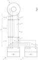
- Fig. 3 shows a circuit diagram of the connecting means 3 of an exemplary embodiment of a device for generating electrical energy, in particular a wind turbine with a generator 2 and a converter 4 or 4 '.
- the connecting means 3 between the generator 2 and the converter 4 or 4 ' are three-phase L1, L2, L3 or L1', L2', L3'.
- the generator 3 is also connected to the converter 4 or 4' via a neutral conductor N or N'.
- the neutral conductor N, N' is part of the machine-side connecting means 3.
- the connecting means 3 is divided into three areas A, B and C, with area B being designed, for example, as a busbar, for example in the tower of a wind turbine. Areas A and C should, for example, be designed as cables.
- Means for damping the series resonance of the connecting means 3 in the zero system 5, 6, 7, 8 and 9 are in Fig. 3 also shown, whereby the means shown for damping the series resonance 5, 6, 7, 8 and 9 are intended to illustrate in particular the different possible positions of the damping means.
- the means for damping the series resonance in the zero system 5, 6, 7, 8 and 9 are designed as series resistors that are magnetically coupled into the zero conductor N and through the annular magnetic core Fig. 3 symbolized.
- the means for damping the series resonance 5, 6, 7, 8 and 9 can be provided in areas A, B and C of the connecting means. If, for example, the neutral conductor N is implemented in area B by the metallic tower wall of a wind turbine, the magnetic coupling of the means for damping the series resonance cannot take place in this area. In this case it can also a different position for the magnetic coupling of a series resistor 5, 7, 8 or 9 can be used to dampen the series resonance, for example in the cable routed areas A and C.
- the cable-guided areas A and C of the connecting means 3 are preferably chosen for the magnetic coupling of the series resistance, since in these areas the magnetic coupling of the series resistance can be achieved in a simple manner with relatively small magnetic cores.
- the position of the means for damping the series resonance for example the position of the magnetic core for coupling in the series resistance, can be arranged in the different areas A, B or C of the multi-phase connecting means 3 depending on the circumstances. Since the neutral conductor N or N' is not designed to transmit large amounts of energy, it has smaller geometric dimensions than the other power phases. The arrangement of a magnetic core on the neutral conductor can therefore be done in a simple manner. In areas B and C, as already explained, this is particularly easy because the neutral conductor N or N 'is designed as a cable here. However, it is also conceivable that damping means are provided in several areas A, B and C.
- Figs. 4 and 5 now show a magnetic core made of soft magnetic solid material 10, preferably ferrite, which encloses a neutral conductor N and has at least one coil 11, which is connected or short-circuited via at least one series resistor 12. While Fig. 4 a sectional view perpendicular to the longitudinal axis of the neutral conductor N is shown in Fig. 5 a top view of the neutral conductor N is shown.
- the soft magnetic ring 10 encloses the neutral conductor N perpendicular to its longitudinal extent.
- the changing magnetic field induced in the magnetic core generates a voltage in the coil 11, which leads to a current flow across the series resistor 12.
- the magnetic core 10 which is made of soft magnetic solid material, in particular ferrite, has very little Heat losses occur due to the induction of alternating magnetic fields in the magnetic core, so that the heat loss in the soft magnetic, for example ferritic ring, remains low. Essentially the heat loss is then released in the series resistor 12 due to the damping of the series resonance.
- the in Figs. 4 and 5 The series resistance shown can preferably be set variably in its resistance value. This has the advantage that, for example, at the location where a wind turbine is installed, the series resistance can still be adjusted to optimize the damping of the series resonance after assembly. The same applies when retrofitting an existing device for generating electrical energy.
- FIG. 6 Another, simple way to magnetically couple a series resistance into the zero system is shown Fig. 6 in a schematic sectional view.
- a magnetic core 10' consisting of electrical sheet metal is shown here.
- the magnetic core has a defined gap so that a defined magnetic resistance can be set.
- the neutral conductor is also shown, which the magnetic core 10 'encloses.
- the magnetic core 10 'constructed in this way already provides the series resistance in which, during the change in the magnetization direction due to the series resonance, the magnetic resistance leads to heat loss and thus to a damping of the series resonance.
- the resulting heat loss is released throughout the entire magnetic core 10' and in this case must be sufficiently dissipated.
- the advantage of the laminated magnetic core 10' is that it is inexpensive and its geometric shape can be chosen relatively freely.
Description
Die Erfindung betrifft eine Vorrichtung zur Erzeugung elektrischer Energie, insbesondere eine Windenergieanlage, mit mindestens einem Generator, wobei der Generator elektrische Energie über mehrphasige, maschinenseitige Verbindungsmittel bereitstellt und mit mindestens einem Umrichter mit Gleichspannungszwischenkreis über die mehrphasigen, maschinenseitigen Verbindungsmittel elektrisch verbunden ist. Darüber hinaus betrifft die Erfindung ein Verfahren zum Betreiben einer Vorrichtung zur Erzeugung elektrischer Energie, insbesondere eine Windenergieanlage.The invention relates to a device for generating electrical energy, in particular a wind turbine, with at least one generator, the generator providing electrical energy via multi-phase, machine-side connecting means and being electrically connected to at least one converter with a DC intermediate circuit via the multi-phase, machine-side connecting means. In addition, the invention relates to a method for operating a device for generating electrical energy, in particular a wind turbine.
Gattungsgemäße Vorrichtungen zur Erzeugung elektrischer Energie, beispielsweise Windenergieanlagen weisen einen die elektrische Energie erzeugenden Generator auf, welcher von einer weiteren Energiequelle gespeist wird, so dass dieser elektrische Energie erzeugen kann. Bei Windenergieanlagen sind dies die Windrotoren, die den Generator antreiben. Die elektrische Energie wird bei den heute eingesetzten Windenergieanlagen über Umrichter in das elektrische Netz eingespeist. Umrichter enthalten Leistungsschalter, welche den von der Maschinenseite des Umrichters eingehenden mehrphasigen, z.B. dreiphasigen Wechselstrom des Generators in einen Gleichspannungszwischenkreis einspeisen und aus diesem an die Netzfrequenz und Netzspannung angepassten Wechselstrom netzseitig erzeugen und in das Netz einspeisen.Generic devices for generating electrical energy, for example wind turbines, have a generator that generates the electrical energy and is fed by another energy source so that it can generate electrical energy. In wind turbines, these are the wind rotors that drive the generator. In the wind turbines used today, the electrical energy is fed into the electrical network via converters. Converters contain circuit breakers which feed the multi-phase, e.g. three-phase alternating current from the generator coming from the machine side of the converter into a DC intermediate circuit and from this generate alternating current on the network side that is adapted to the mains frequency and mains voltage and feed it into the network.
Aus Platzgründen aber häufig auch aus Sicherheitsgründen sind Generator und Umrichter in der Regel räumlich getrennt angeordnet. Bei Windenergieanlagen ist der Platzbereich in der Gondel, in welcher der Generator angeordnet sein muss, beschränkt, so dass der oder die Umrichter häufig im oder am Fuß der Windenergieanlage angeordnet sind. Hierdurch ergeben sich lange elektrische Verbindungswege zwischen Generator und Umrichter. Für die elektrischen Verbindungen werden maschinenseitig mehrphasige Verbindungsmittel eingesetzt, welche sowohl durch Kabel als auch durch Stromschienen realisiert sein können. Oft wird auch eine Kombination aus Kabel und Stromschienen für die mehrphasigen maschinenseitigen Verbindungsmittel verwendet. Beispielsweise können die mehrphasigen, maschinenseitigen Verbindungsmittel zunächst vom Generator in den Turm der Windenergieanlage als Kabelstrecke ausgeführt sein. Die Kabelstrecke kann leichter der Rotation der Gondel folgen. Anschließend werden die mehrphasigen, maschinenseitigen Verbindungsmittel als Stromschienen ausgebildet, da diese auf einfache Weise in dem Bauteile des Turms bereits vorkonfektioniert werden können, so dass nur noch die einzelnen Bauteile des Turms elektrisch miteinander verbunden werden müssen. Weiter werden die mehrphasigen, maschinenseitigen Verbindungsmittel häufig wieder über Kabelstrecken an den maschinenseitigen Anschluss des Umrichters geführt. Aufgrund des geometrischen Aufbaus von Kabeln und Stromschienen entstehen parasitäre Induktivitäten und Kapazitäten, die zu ungewollten Spannungsspitzen im Betrieb der Vorrichtung bzw. der Windenergieanlage am maschinenseitigen Eingang des Umrichters führen können. Die Spannungsspitzen treten zwischen den einzelnen Phasen und dem Nullpotential auf, wobei der dominante Anteil vom Nullsystem gebildet wird. Mit- und Gegensystem haben nur einen untergeordneten Anteil an diesen Spannungsspitzen. Die Begriffe Nullsystem, Mitsystem und Gegensystem sind dem Fachmann als symmetrische Komponentenzerlegung bekannt und werden hier nicht im Detail weiter erläutert.For reasons of space, but also often for safety reasons, the generator and converter are usually arranged spatially separately. In wind turbines, the space in the nacelle in which the generator must be arranged is limited, so that the converter or converters are often arranged in or at the base of the wind turbine. This results in long electrical connection paths between the generator and the converter. For the electrical ones For connections, multi-phase connecting means are used on the machine side, which can be implemented using both cables and busbars. A combination of cables and busbars is often used for the multi-phase machine-side connecting means. For example, the multi-phase, machine-side connecting means can initially be designed as a cable route from the generator into the tower of the wind turbine. The cable route can more easily follow the rotation of the nacelle. The multi-phase, machine-side connecting means are then designed as busbars, since these can easily be pre-assembled in the components of the tower, so that only the individual components of the tower need to be electrically connected to one another. Furthermore, the multi-phase, machine-side connecting means are often routed via cable routes to the machine-side connection of the converter. Due to the geometric structure of cables and busbars, parasitic inductances and capacitances arise, which can lead to unwanted voltage peaks during operation of the device or the wind turbine at the machine-side input of the converter. The voltage peaks occur between the individual phases and the zero potential, with the dominant portion being formed by the zero system. The positive and negative systems only play a minor role in these voltage peaks. The terms zero system, positive system and negative system are known to those skilled in the art as symmetrical component decomposition and will not be explained in further detail here.
Es ist zwar bekannt generatorseitig des Umrichters diesen Effekt der parasitären Induktivitäten und Kapazitäten über sogenannte dU/dt-Filter zu vermeiden. Diese generatorseitigen dU/dt-Filter sind jedoch üblicherweise sowohl für das Mit-, das Gegen- und Nullsystem bei gleichzeitig deutlich niedrigeren parasitären Induktivitäten und Kapazitäten der Verbindungsmittel vorgesehen, so dass diese auf Frequenzen im Bereich 1 MHz ausgelegt sind. dU/dt-Filter sollen bei geringen parasitären Kapazitäten und Induktivitäten zudem die Flankensteilheit der Spannung auf bestimmte Werte begrenzen. Hierzu weisen dU/dt-Filter in vielen üblichen Ausführungsformen optimierte Bauformen mit relativ geringen Induktivitäten im Nullsystem auf, so dass Überspannungen gegen Nullpotential der maschinenseitigen Verbindungsmittel in der Regel nicht beeinflusst werden. Auch die Auswahl eines spezifischen Ansteuerungsmusters für die einzelnen Leistungsschalter der Umrichter, beispielsweise durch Verzögerung von einzelnen Schaltimpulsen, um den spezifischen Spannungssprüngen entgegenzuwirken, hat zu keiner Verringerung der Überspannung geführt, da die Überspannungen dann für andere Schaltzustände des Umrichters auftraten. Eine deutliche Verringerung der Überspannungen kann zwar durch eine Verringerung der parasitären Induktivitäten und Kapazitäten der maschinenseitigen Verbindungsmittel erreicht werden. Dies führt aber als technische Zusatzanforderung an die Verbindungsmittel in der Regel zu erhöhten Kosten..It is known to avoid this effect of parasitic inductances and capacitances on the generator side of the converter using so-called dU/dt filters. However, these generator-side dU/dt filters are usually intended for the positive, negative and zero systems with significantly lower parasitic inductances and capacitances of the connecting means, so that they are designed for frequencies in the 1 MHz range. dU/dt filters are also intended to limit the voltage slope to certain values with low parasitic capacitances and inductances. For this purpose, dU/dt filters in many common embodiments have optimized designs with relatively low inductances Zero system, so that overvoltages against zero potential of the machine-side connecting means are generally not influenced. The selection of a specific control pattern for the individual power switches of the converters, for example by delaying individual switching pulses to counteract the specific voltage jumps, did not lead to a reduction in the overvoltage, since the overvoltages then occurred for other switching states of the converter. A significant reduction in overvoltages can be achieved by reducing the parasitic inductances and capacitances of the machine-side connecting means. However, as an additional technical requirement for the connecting means, this usually leads to increased costs.
Aus der US-Patentschrift
Aus der US-amerikanischen Offenlegungsschrift
Die
Der vorliegenden Erfindung liegt daher die Aufgabe zu Grunde, eine Vorrichtung zur Erzeugung elektrischer Energie, insbesondere einer Windenergieanlage bereitzustellen, welche trotz parasitärer Induktivitäten und Kapazitäten der maschinenseitigen, mehrphasigen Verbindungsmittel die Entstehung von Überspannungen zuverlässig vermeidet.The present invention is therefore based on the object of providing a device for generating electrical energy, in particular a wind turbine, which reliably avoids the creation of overvoltages despite parasitic inductances and capacitances of the machine-side, multi-phase connecting means.
Erfindungsgemäß wird die aufgezeigte Aufgabe für eine Vorrichtung zur Erzeugung elektrischer Energie, insbesondere für eine Windenergieanlage dadurch gelöst, dass Mittel zur Dämpfung mindestens einer, vorzugsweise der ersten Serienresonanz im Nullsystem der maschinenseitigen Verbindungsmittel zwischen Generator und Umrichter vorgesehen sind. Vorzugsweise wird die erste Serienresonanz gedämpft.According to the invention, the stated object for a device for generating electrical energy, in particular for a wind turbine, is achieved in that means for damping at least one, preferably the first, series resonance in the zero system of the machine-side connecting means between the generator and the converter are provided. Preferably the first series resonance is dampened.
Der Erfinder hat aus Modellrechnungen zu den maschinenseitigen, mehrphasigen Verbindungsmitteln erkannt, dass in den mehrphasigen, maschinenseitigen Verbindungsmitteln zwischen Generator und Umrichter die detektierten Überspannungen durch eine nicht gedämpfte Serienresonanz im Nullsystem, insbesondere durch die erste Serienresonanz entstehen. Sind Mittel zur Dämpfung dieser mindestens einen Serienresonanz im Nullsystem der maschinenseitigen Verbindungsmittel vorgesehen, wird die Resonanzstelle im Frequenzband entsprechend gedämpft und die Überspannungen stark reduziert. Es hat sich herausgestellt, dass die Serienresonanz durch Schaltvorgänge der Leistungsschalter der Umrichter, bei welchen ein breitbandiges Spektrum im Frequenzbereich bzw. steile Spannungs-Flanken im Zeitbereich in den Verbindungsmitteln aufgeschaltet werden, dazu führt, dass diese durch übliche Dimensionierung der dU/dt-Filter nicht gedämpfte Serienresonanz angeregt wird und zu den gemessenen Überspannungen führt. Eine Dämpfung dieser Serienresonanz führt im Ergebnis zu deutlich verringerten Überspannungen auf einen Wert, der für die elektrische Belastung der maschinenseitigen Verbindung zwischen Umrichter und Generator zulässig ist. Die Erfindung ist hinsichtlich des technischen Aufwands besonders dann effektiv, wenn der Wert der parasitären Induktivitäten und Kapazitäten der maschinenseitigen Verbindung zwischen Umrichter und Generator erheblich höher ist als für eine übliche Dimensionierung des dU/dt-Filters vorausgesetzt.The inventor recognized from model calculations for the machine-side, multi-phase connecting means that in the multi-phase, machine-side connecting means between generator and converter, the detected overvoltages arise from an undamped series resonance in the zero system, in particular from the first series resonance. If means for damping this at least one series resonance are provided in the zero system of the machine-side connecting means, the resonance point in the frequency band is correspondingly dampened and the overvoltages are greatly reduced. It has been found that the series resonance caused by switching operations of the power switches of the converters, in which a broadband spectrum in the frequency range or steep voltage edges in the time range are switched on in the connecting means, leads to this being caused by the usual dimensioning of the dU/dt filters undamped series resonance is excited and leads to the measured overvoltages. Damping this series resonance results in significantly reduced overvoltages to a value that is permissible for the electrical load on the machine-side connection between the converter and generator. The invention is particularly effective in terms of technical effort when the value of the parasitic inductances and capacitances on the machine side The connection between the inverter and the generator is considerably higher than is assumed for the usual dimensioning of the dU/dt filter.
Gemäß einer ersten Ausgestaltung weisen die Mittel zur Dämpfung der mindestens einen, vorzugsweise der ersten Serienresonanz im Nullsystem der maschinenseitigen Verbindungsmittel mindestens einen in das Nullsystem der maschinenseitigen Verbindungsmittel magnetisch eingekoppelten Serienwiderstand auf. Dieser Serienwiderstand im Nullsystem der maschinenseitigen Verbindungsmittel führt zu einer ausreichenden Dämpfung der Serienresonanz bei relativ geringer zusätzlicher Verlustleistung. Die Verlustleistung beträgt für eine ausreichende Dämpfung weniger als 2 kW bei einer Leistungsabgabe von mehreren Megawatt.According to a first embodiment, the means for damping the at least one, preferably the first, series resonance in the zero system of the machine-side connecting means have at least one series resistance that is magnetically coupled into the zero system of the machine-side connecting means. This series resistance in the zero system of the machine-side connecting means leads to sufficient damping of the series resonance with relatively low additional power loss. For sufficient attenuation, the power loss is less than 2 kW with a power output of several megawatts.
Vorzugsweise weist der mindestens eine magnetisch eingekoppelte Serienwiderstand im Nullsystem einen elektrischen Widerstand R auf, für den zur Festlegung der Dämpfung folgende Beziehung sinnvoll definiert wird: ![]()
![]()
![]()
![]()
Durch die Wahl des Serienwiderstandswertes entsprechend der zuvor genannten Gleichung (1) unter Berücksichtigung eines Proportionalitätsfaktors d im Bereich von 0,25 bis 1,8 wird eine gute Dämpfung der Serienresonanz erzielt. Entsprechende Widerstandswerte betragen beispielsweise maximal 10 Ω, bevorzugt 1 bis 5 Ω. Bevorzugt wird der mindestens eine magnetisch eingekoppelte Serienwiderstand im Nullsystem der maschinenseitigen Verbindungsmittel über mindestens einen magnetischen Kern eingekoppelt, sodass auf einfache Weise eine Dämpfung der Serienresonanz der maschinenseitigen Verbindungsmittel erzielt wird.By choosing the series resistance value according to the aforementioned equation (1), taking into account a proportionality factor d in the range from 0.25 to 1.8, good damping of the series resonance is achieved. Corresponding resistance values are, for example, a maximum of 10 Ω, preferably 1 to 5 Ω. The at least one magnetically coupled series resistance in the zero system of the machine-side connecting means is preferred via at least one coupled into the magnetic core, so that a damping of the series resonance of the machine-side connecting means is achieved in a simple manner.
Der mindestens eine magnetische Kern umschließt vorzugsweise gemäß einer weiteren Ausgestaltung den Null-Leiter der maschinenseitigen Verbindungsmittel zwischen Umrichter und Generator zur magnetischen Einkopplung des Serienwiderstands. Das Umschließen des Null-Leiters führt dazu, dass der magnetische Kern das durch den Stromfluss im Nullsystem erzeugte Magnetfeld zwischen Umrichter und Verbindungsmitteln zum Generator verstärkt. Dabei kann ein Umschließen auch bedeuten, dass der magnetische Kern als Ring um den Null-Leiter mit oder ohne einen Spalt ausgebildet ist. Über den Null-Leiter der maschinenseitigen Verbindungsmittel werden keine hohen Leistungen bzw. Ströme geführt, deshalb sind die entstehenden Magnetfelder und damit auch die Verlustleistungen im Serienwiderstand gering im Vergleich zu den Magnetfeldern, die durch die Ströme der Hauptverbindungsleitern, also der Leistungsphasen entstehen. Aus diesem Grund ist der Null-Leiter auch in der Regel in den geometrischen Abmessungen klein ausgebildet und leicht mit einem magnetischen Kern zu umschließen. Die Anordnung des magnetischen Kerns zur Umschließung des Null-Leiters erfordert insofern nur einen verhältnismäßig geringen Aufwand.According to a further embodiment, the at least one magnetic core preferably encloses the neutral conductor of the machine-side connecting means between the converter and generator for magnetic coupling of the series resistance. Enclosing the neutral conductor causes the magnetic core to strengthen the magnetic field generated by the current flow in the zero system between the converter and the connecting means to the generator. Enclosing can also mean that the magnetic core is designed as a ring around the neutral conductor with or without a gap. No high powers or currents are carried via the neutral conductor of the machine-side connecting means, which is why the resulting magnetic fields and thus also the power losses in the series resistance are low compared to the magnetic fields that arise from the currents of the main connecting conductors, i.e. the power phases. For this reason, the neutral conductor is generally small in geometric dimensions and is easy to enclose with a magnetic core. The arrangement of the magnetic core to enclose the neutral conductor requires only relatively little effort.
Ist der Null-Leiter der maschinenseitigen Verbindungsmittel zumindest bereichsweise als Kabel und/oder als Stromschiene ausgebildet, kann der mindestens eine magnetische Kern auf einfache Weise mindestens in einem dieser Bereiche angeordnet sein, um den Serienwiderstand magnetisch einzukoppeln.If the neutral conductor of the machine-side connecting means is designed at least in some areas as a cable and/or as a busbar, the at least one magnetic core can be arranged in a simple manner at least in one of these areas in order to magnetically couple the series resistance.
Gemäß einer ersten Variante der magnetischen Einkopplung weist der mindestens eine magnetische Kern Elektroblech auf, wobei optional ein Luftspalt zur Bereitstellung eines spezifischen magnetischen Widerstands des magnetischen Kerns vorgesehen ist. In der Variante des magnetischen Kerns aus Elektroblech ist der Frequenzbereich für den zu übertragenden Strom begrenzt, so dass der entsprechende magnetische Kern bereits bei hohen Frequenzen dämpfend wirkt.According to a first variant of the magnetic coupling, the at least one magnetic core has electrical sheet metal, with an air gap optionally being provided to provide a specific magnetic resistance of the magnetic core. In the variant of the magnetic core made of electrical sheet metal, the frequency range for the current to be transmitted is limited, so that the corresponding magnetic core already has a damping effect at high frequencies.
Aufgrund des magnetischen Widerstandes im Bereich des Luftspalts wird zudem eine spezifische Induktivität und damit ein spezifischer Serienwiderstand über den magnetischen Kern bereitgestellt. In diesem Fall entsteht im gesamten magnetischen Kern Verlustwärme aufgrund der Resonanzdämpfung. Der Elektroblech aufweisende magnetische Kern ist spezifisch zu seinem Gewicht besonders kostengünstig in seiner Herstellung, leicht verfügbar, benötigt aber besondere Kühlungsmaßnahmen, da die Wärme im gesamten magnetischen Kern frei wird. Außerdem sind dessen Abmessungen mit Rücksicht auf seine elektrischen Eigenschaften größer zu wählen im Vergleich zu anderen magnetischen Materialien.Due to the magnetic resistance in the area of the air gap, a specific inductance and thus a specific series resistance is also provided via the magnetic core. In this case, heat loss occurs in the entire magnetic core due to resonance damping. The magnetic core having electrical steel is particularly cost-effective to produce, given its weight, and is easily available, but requires special cooling measures because the heat is released throughout the entire magnetic core. In addition, its dimensions should be larger compared to other magnetic materials, taking into account its electrical properties.
Gemäß der zweiten Ausführungsform besteht der magnetische Kern aus einem anderen weichmagnetischen Vollmaterial, vorzugsweise Ferrit, wobei der mindestens eine magnetische Kern mindestens eine Spule aufweist, deren Wicklungsanschlüsse über mindestens einen Serienwiderstand miteinander verbunden sind. Weichmagnetische Vollmaterialien weisen geringe Koerzitivfeldstärken auf. Die Dämpfungseigenschaften von Ferrit sind aufgrund seiner wesentlich niedrigeren Verluste aufgrund geringer Koerzitivfeldstärken gering. Aus diesem Grund ist auf dem weichmagnetischen Kern eine Spule angeordnet, die mit einem Serienwiderstand verbunden ist. In der Spule wird durch das wechselnde Magnetfeld im magnetischen Kern eine Spannung erzeugt, die über den Serienwiderstand zu einem Stromfluss führt. Durch die Auswahl der Anzahl der Wicklungen der Spule, zumeist weniger als 10, z.B. 2 bis 6 und durch die Auswahl des Serienwiderstands kann die Dämpfungsleistung dieser Anordnung sehr genau eingestellt werden. Hiermit kann die Reduktion der Spannungsspitzenwerte gemäß Gleichung (1) sehr genau eingestellt werden.According to the second embodiment, the magnetic core consists of another soft magnetic solid material, preferably ferrite, wherein the at least one magnetic core has at least one coil, the winding connections of which are connected to one another via at least one series resistor. Soft magnetic solid materials have low coercivity. The damping properties of ferrite are low due to its significantly lower losses due to low coercivity. For this reason, a coil is arranged on the soft magnetic core and is connected to a series resistor. The changing magnetic field in the magnetic core creates a voltage in the coil, which leads to a current flow via the series resistance. By selecting the number of windings of the coil, usually less than 10, e.g. 2 to 6, and by selecting the series resistance, the damping performance of this arrangement can be set very precisely. This allows the reduction of the voltage peak values according to equation (1) to be set very precisely.
Der Widerstand des Serienwiderstands beträgt wenige Ω, beispielsweise maximal 10 Ω, so dass auf Standardbauelemente zurückgegriffen und die Kosten der Anordnung stark reduziert werden können. Die Dämpfungsleistung wird im Wesentlichen in Wärme über den Serienwiderstand umgewandelt. Gleichzeitig kann der Widerstand exakt auf die zu erwartende Dämpfungsleistung und damit auf die zu erwartende Verlustleistung abgestimmt werden. Bei einer geringen zu erwartenden Verlustleistung kann die natürliche Konvektion zur Kühlung des Serienwiderstands ausreichend sein, so dass keine zusätzlichen Kühlmittel benötigt werden.The resistance of the series resistor is a few Ω, for example a maximum of 10 Ω, so that standard components can be used and the costs of the arrangement can be greatly reduced. The damping power is essentially converted into heat via the series resistance. At the same time, the resistance can be adjusted exactly to the expected damping performance and thus to the expected Power loss must be coordinated. If the expected power loss is low, natural convection can be sufficient to cool the series resistor, so that no additional coolant is required.
Ist der mindestens eine Serienwiderstand gemäß einer weiteren Ausgestaltung bevorzugt auf Kühlmitteln angeordnet und optional im Widerstandswert variabel einstellbar, können auch höhere Verlustleistungen in Form von Wärme sicher abgeführt werden. Ein variabel einstellbarer Serienwiderstand erlaubt es dabei, den Serienwiderstand erst vor Ort, z. B. nach dem Aufbau einer Windenergieanlage, an unterschiedliche Gegebenheiten nachträglich einzustellen und damit eine Optimierung der Dämpfung der Serienresonanz bei gleichzeitig geringen Verlusten zu ermöglichen. Die Kühlmittel, auf welchen der Serienwiderstand angeordnet ist, können aktive, beispielsweise von Kühlmedium durchflossene Kühlmittel oder passive, beispielsweise lediglich als Kühlkörper ausgebildete Kühlmittel sein. Die Dimensionierung dieser Kühlmittel erlaubt es, die berechnete Verlustleistung am Serienwiderstand über die Kühlmittel mit geringem Aufwand sicher abzuführen.If the at least one series resistor is preferably arranged on coolants according to a further embodiment and the resistance value can optionally be variably adjusted, even higher power losses can be safely dissipated in the form of heat. A variably adjustable series resistance allows the series resistance to be set on site, e.g. B. after the construction of a wind turbine, to be subsequently adjusted to different circumstances and thus enable optimization of the attenuation of the series resonance while at the same time keeping losses low. The coolants on which the series resistor is arranged can be active coolants, for example through which cooling medium flows, or passive coolants, for example only designed as heat sinks. The dimensioning of these coolants allows the calculated power loss at the series resistance to be safely dissipated via the coolant with little effort.
Vorzugsweise sind die maschinenseitigen Verbindungsmittel so dimensioniert, dass die Serienresonanz der Verbindungsmittel im System unterhalb einer Frequenz von 500 kHz, bevorzugt unterhalb einer Frequenz von 150 kHz auftritt. Die Serienresonanz ergibt sich näherungsweise aus der Gleichung: ![]()
![]()
Die Kapazität C und die Induktivität L der maschinenseitigen Verbindungsmittel ergeben sich aus den geometrischen Abmessungen der maschinenseitigen Verbindungsmittel sowie deren Anordnung, beispielsweise im Turm der Windenergieanlage. Treten die Serienresonanzen im Nullsystem unterhalb einer Frequenz von 500 kHz auf bzw. unter einer Frequenz von 150 kHz auf, so können die Resonanzen nicht über die üblicherweise vorgesehenen Netzfilter (dU/dt-Filter) gedämpft werden. Diese arbeiten, wie bereits ausgeführt, in einem deutlich höheren Frequenzband, etwa bei 1 MHz. Gerade für diese niedrigen Serienresonanzfrequenzen kann die erfindungsgemäße Vorrichtung eine effektive Dämpfung der mindestens einen, vorzugsweise der ersten Serienresonanz bei gleichzeitiger geringer Verlustleistung bereitstellen.The capacity C and the inductance L of the machine-side connecting means result from the geometric dimensions of the machine-side connecting means and their arrangement, for example in the tower of the wind turbine. If the series resonances in the zero system occur below a frequency of 500 kHz or below a frequency of 150 kHz, the resonances cannot be attenuated using the normally provided mains filters (dU/dt filters). As already stated, these work at a significantly higher rate Frequency band, approximately at 1 MHz. Especially for these low series resonance frequencies, the device according to the invention can provide effective attenuation of the at least one, preferably the first, series resonance with at the same time low power loss.
Als erste Serienresonanz(-frequenz) wird die Resonanz(-frequenz) bezeichnet, welche den geringsten Widerstand aufweist, also deren Schwingungen am wenigstens gedämpft werden. Diese tritt in der Regel bei der Resonanz mit der geringsten Frequenz auf. Alle höheren Serienresonanzen weisen üblicherweise auch höhere Dämpfungen auf.The first series resonance (frequency) is the resonance (frequency) that has the lowest resistance, i.e. whose oscillations are least attenuated. This usually occurs at the resonance with the lowest frequency. All higher series resonances usually also have higher attenuation.
Gemäß einer weiteren Ausgestaltung der Vorrichtung ist die Vorrichtung eine Windenergieanlage, wobei die Windenergieanlage als Generator eine doppeltgespeiste Asynchronmaschine, oder einen Synchrongenerator aufweist. Beide Generatortypen sind über einen maschinenseitigen Umrichter an einen Gleichspannungszwischenkreis und darüber an einen netzseitigen Umrichter angeschlossen, so dass die vom Generator bereitgestellte elektrische Energie in geeigneter Form in das elektrische Versorgungsnetz eingespeist werden kann. Beide Typen von Windenergieanlagen zeichnen sich dadurch durchaus, dass üblicherweise die Umrichter nicht in der Gondel, also in unmittelbarer Nähe des Generators angeordnet sind. Die Umrichter sind daher über lange Verbindungsmittel maschinenseitig mit den Generatoren verbunden, was zu höheren parasitären Induktivitäten und Kapazitäten führen kann. Die Dämpfung mindestens einer, vorzugsweise der ersten Serienresonanz führt bei beiden Anlagentypen insofern zu einem verbesserten Spannungsverhalten am maschinenseitigen Eingang des Umrichters.According to a further embodiment of the device, the device is a wind turbine, wherein the wind turbine has a double-fed asynchronous machine or a synchronous generator as a generator. Both generator types are connected via a machine-side converter to a DC intermediate circuit and then to a grid-side converter, so that the electrical energy provided by the generator can be fed into the electrical supply network in a suitable form. Both types of wind turbines are characterized by the fact that the converters are usually not arranged in the nacelle, i.e. in the immediate vicinity of the generator. The converters are therefore connected to the generators on the machine side via long connecting means, which can lead to higher parasitic inductances and capacitances. The damping of at least one, preferably the first, series resonance leads to improved voltage behavior at the machine-side input of the converter in both types of systems.
Gemäß einer weiteren Lehre der vorliegenden Erfindung wird die oben aufgezeigte Aufgabe durch ein Verfahren zum Betreiben einer Vorrichtung zur Erzeugung elektrischer Energie, insbesondere einer Windenergieanlage dadurch gelöst, dass mindestens eine, vorzugsweise die erste Serienresonanz im Nullsystem der maschinenseitigen Verbindungsmittel zwischen Generator und Umrichter ermittelt wird, abhängig von der ermittelten Serienresonanz ein Serienwiderstand zur Dämpfung dieser Serienresonanz bestimmt wird und dieser Serienwiderstand in das Nullsystem magnetisch eingekoppelt wird.According to a further teaching of the present invention, the object set out above is achieved by a method for operating a device for generating electrical energy, in particular a wind turbine, in that at least one, preferably the first, series resonance is determined in the zero system of the machine-side connecting means between the generator and the converter depending on the determined series resonance, a series resistance is determined for damping this series resonance and this series resistance is magnetically coupled into the zero system.
Wie bereits zuvor ausgeführt erlaubt die Dämpfung der Serienresonanz im Nullsystem über ein magnetisches Einkoppeln eines Serienwiderstands Spannungsspitzen aufgrund der parasitären Induktivitäten und Kapazitäten der maschinenseitigen Verbindungsmittel am Umrichtereingang zu vermeiden und diese stark zu dämpfen. Gleichzeitig kann das Verfahren dabei über die magnetische Einkopplung des Serienwiderstandes eine geringe Verlustleistung bereitstellen.As already explained above, the damping of the series resonance in the zero system via magnetic coupling of a series resistor allows voltage peaks due to the parasitic inductances and capacitances of the machine-side connecting means at the converter input to be avoided and to be strongly dampened. At the same time, the method can provide low power loss via the magnetic coupling of the series resistance.
Die Erfindung soll im Weiteren anhand von Ausführungsbeispielen in Verbindung mit der Zeichnung näher erläutert werden. In der Zeichnung zeigt:
- Fig. 1
- in einer schematischen Darstellung eine Vorrichtung zur Erzeugung elektrischer Energie in Form einer Windenergieanlage,
- Fig. 2
- eine Simulation der Spannungsüberhöhung aufgrund einer Serienresonanz in einem Spannungszeitdiagramm einer Phase gegen Null-Potential am maschinenseitigen Eingang des Umrichters,
- Fig. 3
- ein Ausführungsbeispiel einer Schaltskizze der Verbindungsmittel vom Generator zum Umrichter,
- Fig. 4, 5
- in einer Schnittansicht sowie in einer Draufsicht ein Ausführungsbeispiel eines magnetisch gekoppelten Serienwiderstands und
- Fig. 6
- ein weiteres Ausführungsbeispiel eines magnetisch eingekoppelten Serienwiderstands mit einem geblechten magnetischen Kern.
- Fig. 1
- in a schematic representation a device for generating electrical energy in the form of a wind turbine,
- Fig. 2
- a simulation of the voltage increase due to a series resonance in a voltage-time diagram of a phase against zero potential at the machine-side input of the converter,
- Fig. 3
- an exemplary embodiment of a circuit diagram of the connecting means from the generator to the converter,
- Fig. 4, 5
- in a sectional view and in a top view an embodiment of a magnetically coupled series resistor and
- Fig. 6
- a further embodiment of a magnetically coupled series resistor with a laminated magnetic core.
Die geometrische Ausgestaltung der Stromschienen im Bereich B in Verbindung mit der Kabelführung in den Bereichen A und C der maschinenseitig vorgesehenen Verbindungsmittel 3 kann parasitäre Induktivitäten und Kapazitäten nicht verhindern, so dass es insbesondere im Nullsystem, d.h. also der Spannung aller Phasen gegenüber dem Nullpotential oder Erde, zu Resonanzen und somit zu unerwünschten Spannungsschwankungen kommt.The geometric design of the busbars in area B in conjunction with the cable routing in areas A and C of the connecting
Zu erkennen ist, dass die ungedämpfte Spannung Uug gegenüber dem Null-Potential während des ersten Schaltvorgangs ein starkes Überschwingen zeigt und in dem dargestellten Fall Werte zwischen ca. 1300 V und -2500 V annimmt. Die Spannungsspitze kann in Bezug auf die Komponenten des Umrichters aber problematisch sein. Bei Spannungsüberschlägen kann es zu Schäden am Umrichter bzw. an den Verbindungsmitteln zum Generator kommen.It can be seen that the undamped voltage U ug shows a strong overshoot compared to the zero potential during the first switching process and in the case shown assumes values between approx. 1300 V and -2500 V. However, the voltage peak can be problematic with regard to the components of the converter. In the event of voltage flashovers, damage to the converter or the connecting means to the generator can occur.
Wie bereits zuvor ausgeführt, hat der Erfinder erkannt, dass Serienresonanzen, insbesondere die erste Serienresonanz im Nullsystem der mehrphasigen Verbindungsmittel 3 die Ursache der Spannungsspitzen sind. Wird diese mindestens eine, vorzugsweise die erste Serienresonanz im Nullsystem der maschinenseitigen Verbindungsmittel 3 zwischen Generator 2 und Umrichter 4 über Mittel zur Dämpfung der Resonanz gedämpft, kommt es zu einer signifikanten Reduktion der Spannungsspitzen. Der entsprechend simulierte Spannungsverlauf Ug in
Darüber hinaus sind in
Die Mittel zur Dämpfung der Serienresonanz 5, 6, 7, 8 und 9 können in den Bereichen A, B und C der Verbindungsmittel vorgesehen sein. Wird im Bereich B beispielsweise der Null-Leiter N durch die metallische Turmwand einer Windenergieanlage realisiert, kann die magnetische Einkopplung der Mittel zur Dämpfung der Serienresonanz in diesem Bereich nicht erfolgen. In diesem Fall kann dann aber auch eine andere Position für die magnetische Einkopplung eines Serienwiderstands 5, 7, 8 oder 9 zur Dämpfung der Serienresonanz, beispielweise in den Kabel geführten Bereichen A und C verwendet werden. Grundsätzlich werden die Kabel geführten Bereiche A und C der Verbindungsmittel 3 bevorzugt zur magnetischen Einkopplung des Serienwiderstands gewählt, da in diesen Bereichen die magnetische Einkopplung des Serienwiderstands auf einfache Weise mit relativ kleinen magnetischen Kernen gelingt.The means for damping the
Der Generator 3 kann, wie in
Der Generator in
Der mindestens eine magnetisch eingekoppelte Serienwiderstand im Nullsystem der Schaltungsskizze in ![]()
![]()
Die Position der Mittel zur Dämpfung der Serienresonanz, beispielsweise die Position des magnetischen Kerns zur Einkopplung des Serienwiderstands kann je nach Gegebenheiten in die verschiedenen Bereiche A, B oder C der mehrphasigen Verbindungsmittel 3 angeordnet sein. Da der Null-Leiter N bzw. N' nicht zur Übertragung großer Energiemengen ausgebildet ist, weist dieser geringere geometrische Abmessungen auf, als die übrigen Leistungsphasen. Die Anordnung eines magnetischen Kerns am Null-Leiter kann daher auf einfache Weise erfolgen. Im Bereich B und C geschieht dies, wie bereits ausgeführt, besonders einfach, da der Null-Leiter N bzw. N' hier als Kabel ausgeführt ist. Denkbar ist aber auch, dass in mehreren Bereichen A, B und C Dämpfungsmittel vorgesehen sind.The position of the means for damping the series resonance, for example the position of the magnetic core for coupling in the series resistance, can be arranged in the different areas A, B or C of the multi-phase connecting
Die
Der Serienwiderstand 12 wird daher bevorzugt auf nicht dargestellten Kühlmitteln angeordnet, welche die sichere Wärmeabgabe auf einfache Weise gewährleisten. Die Verwendung eines ferritischen Kerns 10 hat den Vorteil, dass die durch die Dämpfung der Serienresonanz entstehende Verlustwärme, gezielt an Kühlmittel übergeben werden kann. Darüber hinaus lässt sich über die Wahl des Serienwiderstands im Widerstandswert als auch über die Anzahl der Wicklungen der Spule auf dem magnetischen Kern ein optimiertes Dämpfungsverhalten in Bezug auf die zu dämpfende Serienresonanz einstellen. Die Anzahl der Wicklungen beträgt vorzugsweise unter 10, besonders bevorzugt 2 bis 6 Windungen.The
Der in
Eine weitere, einfache Möglichkeit einen Serienwiderstand magnetisch in das Nullsystem einzukoppeln zeigt
Der so aufgebaute magnetische Kern 10' stellt bereits selbst den Serienwiderstand zur Verfügung, in dem während der Änderung der Magnetisierungsrichtung aufgrund der Serienresonanz, jeweils der magnetische Widerstand zu Verlustwärme und damit zu einer Dämpfung der Serienresonanz führt. Die entstehende Verlustwärme wird im gesamten magnetischen Kern 10` frei und muss in dem Fall ausreichend abgeführt werden. Der Vorteil des geblechten magnetischen Kerns 10' besteht darin, dass dieser kostengünstig ist und relativ frei in seiner geometrischen Form gewählt werden kann.The magnetic core 10 'constructed in this way already provides the series resistance in which, during the change in the magnetization direction due to the series resonance, the magnetic resistance leads to heat loss and thus to a damping of the series resonance. The resulting heat loss is released throughout the entire magnetic core 10' and in this case must be sufficiently dissipated. The advantage of the laminated magnetic core 10' is that it is inexpensive and its geometric shape can be chosen relatively freely.
Besonders effektiv kann die Vorrichtung gemäß
Vorzugsweise wird dabei die Vorrichtung zur Erzeugung elektrischer Energie, insbesondere die Windenergieanlage derart betrieben, sodass zunächst mindestens eine Serienresonanz im Nullsystem der maschinenseitigen Verbindungsmittel 3 zwischen Generator 2 und Umrichter 4, 4', beispielsweise nach deren Montage oder auch im Vorfeld anhand einer Simulation ermittelt wird und abhängig von der ermittelten Serienresonanz ein Serienwiderstand 5, 6, 7, 8, 9 in das Nullsystem der Verbindungsmittel 3 magnetisch angekoppelt wird. Überspannungen, welche durch das Schaltverhalten der Umrichter im Nullsystem maschinenseitig induziert werden, werden hierdurch signifikant unterdrückt und ein verbessertes Schaltverhalten der Umrichter erzielt.Preferably, the device for generating electrical energy, in particular the wind turbine, is operated in such a way that at least one series resonance in the zero system of the machine-side connecting means 3 between the
Claims (12)
- A device for generating electrical energy, in particular a wind energy installation (1), with at least one generator (2), wherein the generator (2) provides electrical energy via multiphase, machine-side connection means (3) and is electrically connected to at least one converter (4, 4') with DC link via the multiphase, machine-side connection means (3),
characterized in that
means for damping at least one series resonance (5, 6, 7, 8, 9) in the zero system of the machine-side connection means (3) between generator (2) and converter (4, 4') are provided. - The device according to claim 1,
characterized in that
the means for damping the series resonance in the zero system (5, 6, 7, 8, 9) present at least one series resistor (10', 12) coupled-in magnetically which is effective for the zero system of the machine-side connection means (3). - The device according to claim 1 or 2,
characterized in that
the at least one series resistor (10', 12) coupled-in magnetically in the zero system has an electrical resistance R for which holds:

- The device according to any one of claims 1 to 3,
characterized in that
the at least one series resistor (10', 12) coupled-in magnetically in the zero system of the machine-side connection means (3) is coupled-in via at least one magnetic core (10, 10'). - The device according to claim 4,
characterized in that
the at least one magnetic core (10', 11) encloses the neutral conductor (N, N') of the machine-side connection means (3) between converter (4, 4') and generator (2) for magnetically coupling-in the series resistor (10', 12). - The device according to any one of claims 4 and 5,
characterized in that
the neutral conductor (N, N') of the machine-side connection means (3) is formed at least in regions as a cable (A, C) and/or rail (B) and the at least one magnetic core (10, 10') is arranged at least in one of these regions. - The device according to any one of claims 4 to 6,
characterized in that
the at least one magnetic core (10') presents electrical steel, wherein optionally an air gap to provide a specific magnetic resistance of the magnetic core (10') is provided. - The device according to any one of claims 4 to 7,
characterized in that
the at least one magnetic core (10) is made of magnetically soft solid material, preferably ferrite, wherein the at least one magnetic core (10) presents at least one coil (11) whose winding terminals are connected to one another via at least one series resistor (12). - The device according to any one of claims 1 to 8,
characterized in that
the at least one series resistor (12) is arranged on cooling means and optionally its resistance value is variably adjustable. - The device according to any one of claims 1 to 9,
characterized in that
the machine-side connection means (3) are dimensioned such that the series resonance of the connection means (3) in the zero system occurs below 500 kHz, preferably below 150 kHz. - The device according to any one of claims 1 to 10,
characterized in that
the device is a wind energy installation (1), wherein the wind energy installation presents as generator (2) a double-fed asynchronous machine or a synchronous generator. - A method for operating a device for generating electrical energy, in particular a wind energy installation (1) according to any one of claims 1 to 11,
characterized in that
at least one series resonance in the zero system of the machine-side connection means (3) between generator (2) and converter (4, 4') is determined, a series resistance (10', 12) for damping this series resonance is specified depending on the series resonance determined and this series resistance (10', 12) is coupled-in magnetically into the zero system.
Priority Applications (2)
| Application Number | Priority Date | Filing Date | Title |
|---|---|---|---|
| EP19169181.5A EP3726724B1 (en) | 2019-04-15 | 2019-04-15 | Device for creating electrical energy and method |
| US16/849,227 US20200328597A1 (en) | 2019-04-15 | 2020-04-15 | Device for generating electrical energy |
Applications Claiming Priority (1)
| Application Number | Priority Date | Filing Date | Title |
|---|---|---|---|
| EP19169181.5A EP3726724B1 (en) | 2019-04-15 | 2019-04-15 | Device for creating electrical energy and method |
Publications (2)
| Publication Number | Publication Date |
|---|---|
| EP3726724A1 EP3726724A1 (en) | 2020-10-21 |
| EP3726724B1 true EP3726724B1 (en) | 2023-12-13 |
Family
ID=66182385
Family Applications (1)
| Application Number | Title | Priority Date | Filing Date |
|---|---|---|---|
| EP19169181.5A Active EP3726724B1 (en) | 2019-04-15 | 2019-04-15 | Device for creating electrical energy and method |
Country Status (2)
| Country | Link |
|---|---|
| US (1) | US20200328597A1 (en) |
| EP (1) | EP3726724B1 (en) |
Family Cites Families (6)
| Publication number | Priority date | Publication date | Assignee | Title |
|---|---|---|---|---|
| DE10156694B4 (en) * | 2001-11-17 | 2005-10-13 | Semikron Elektronik Gmbh & Co. Kg | circuitry |
| JP4849545B2 (en) * | 2006-02-02 | 2012-01-11 | Necトーキン株式会社 | Amorphous soft magnetic alloy, amorphous soft magnetic alloy member, amorphous soft magnetic alloy ribbon, amorphous soft magnetic alloy powder, and magnetic core and inductance component using the same |
| DE102007048547A1 (en) * | 2006-10-20 | 2008-05-15 | Sekels Gmbh | Radio noise signal suppressor has a ring core with coils and a bridging core of highly magnetic material |
| EP2390891A1 (en) * | 2010-05-24 | 2011-11-30 | ABB Technology AG | A very fast transient suppressing device |
| US9500182B2 (en) | 2012-12-06 | 2016-11-22 | Vestas Wind Systems A/S | Three-phase AC electrical system, and a method for compensating an inductance imbalance in such a system |
| US20150123402A1 (en) | 2013-11-04 | 2015-05-07 | General Electric Company | Magnetic structure combining normal mode and common mode inductance |
-
2019
- 2019-04-15 EP EP19169181.5A patent/EP3726724B1/en active Active
-
2020
- 2020-04-15 US US16/849,227 patent/US20200328597A1/en not_active Abandoned
Also Published As
| Publication number | Publication date |
|---|---|
| US20200328597A1 (en) | 2020-10-15 |
| EP3726724A1 (en) | 2020-10-21 |
Similar Documents
| Publication | Publication Date | Title |
|---|---|---|
| EP1118151B1 (en) | Electrical power transmission system | |
| EP1311058B1 (en) | Frequency power converter | |
| EP0682402B1 (en) | Output magnitudes rise limiting device for self-commutated constant voltage intermediate circuit converter | |
| EP1220431A1 (en) | Damping resonance peaks in an electric motor operated by an inverter with intermediate dc voltage link | |
| EP0682401A1 (en) | Limiting device for the output voltage slope of a self-commutated converter | |
| EP1211788A1 (en) | Damping resonance peaks in an electric motor operated by an inverter with intermediate dc voltage link | |
| EP3785345B1 (en) | Power-electronic device comprising a transformer unit and method | |
| EP3726724B1 (en) | Device for creating electrical energy and method | |
| EP1584134B1 (en) | Method for reducing common-mode interference currents in an electric drive system, and corresponding electric drive system | |
| EP3036811B1 (en) | Method and device for operating an inverter in an inverter-based power distribution system and power distribution system with multiple inverter-based energy transfer units | |
| EP3326285A1 (en) | Apparatus for avoiding harmful bearing currents | |
| EP3393028B1 (en) | Wind turbine with converter system for reducing em radiation | |
| EP3179617B1 (en) | Circuit assembly for the compensation of a dc component in a transformer | |
| EP1217712A2 (en) | Damping of amplified resonances at a motor driven with a constant voltage inverter by amplifying losses in the range of critical self oscillations | |
| EP3721521B1 (en) | Transformer device for transferring harmonic waves | |
| EP2572445B1 (en) | Inverter scalable in power and frequency | |
| DE19861015A9 (en) | Arrangement for feeding electrical power into a 3-phase power grid | |
| EP3446320B1 (en) | Three-phase choke coil | |
| DE19952886A1 (en) | Multi-way current regulator e.g. for electric motor, has local earth provided for each current regulator unit coupled to common line earth via earthing impedance | |
| DE10064213A1 (en) | Frequency converter with mains input choke, includes damping device for oscillatory circuit | |
| EP3637606A1 (en) | Drive system with plurality of inverters | |
| DE102018006788A1 (en) | Wind turbine with improved interference behavior | |
| EP3840207A1 (en) | Low inductance connection of spatially separated power converter arrays | |
| EP4033646A1 (en) | Method and device for reducing harmonics | |
| EP3190677A1 (en) | Wind turbine with improved generator/converter system |
Legal Events
| Date | Code | Title | Description |
|---|---|---|---|
| PUAI | Public reference made under article 153(3) epc to a published international application that has entered the european phase |
Free format text: ORIGINAL CODE: 0009012 |
|
| STAA | Information on the status of an ep patent application or granted ep patent |
Free format text: STATUS: THE APPLICATION HAS BEEN PUBLISHED |
|
| AK | Designated contracting states |
Kind code of ref document: A1 Designated state(s): AL AT BE BG CH CY CZ DE DK EE ES FI FR GB GR HR HU IE IS IT LI LT LU LV MC MK MT NL NO PL PT RO RS SE SI SK SM TR |
|
| RAP1 | Party data changed (applicant data changed or rights of an application transferred) |
Owner name: CONVERTERTEC DEUTSCHLAND GMBH |
|
| STAA | Information on the status of an ep patent application or granted ep patent |
Free format text: STATUS: REQUEST FOR EXAMINATION WAS MADE |
|
| 17P | Request for examination filed |
Effective date: 20210421 |
|
| RBV | Designated contracting states (corrected) |
Designated state(s): AL AT BE BG CH CY CZ DE DK EE ES FI FR GB GR HR HU IE IS IT LI LT LU LV MC MK MT NL NO PL PT RO RS SE SI SK SM TR |
|
| STAA | Information on the status of an ep patent application or granted ep patent |
Free format text: STATUS: EXAMINATION IS IN PROGRESS |
|
| 17Q | First examination report despatched |
Effective date: 20220314 |
|
| GRAP | Despatch of communication of intention to grant a patent |
Free format text: ORIGINAL CODE: EPIDOSNIGR1 |
|
| STAA | Information on the status of an ep patent application or granted ep patent |
Free format text: STATUS: GRANT OF PATENT IS INTENDED |
|
| INTG | Intention to grant announced |
Effective date: 20230704 |
|
| GRAS | Grant fee paid |
Free format text: ORIGINAL CODE: EPIDOSNIGR3 |
|
| GRAA | (expected) grant |
Free format text: ORIGINAL CODE: 0009210 |
|
| STAA | Information on the status of an ep patent application or granted ep patent |
Free format text: STATUS: THE PATENT HAS BEEN GRANTED |
|
| AK | Designated contracting states |
Kind code of ref document: B1 Designated state(s): AL AT BE BG CH CY CZ DE DK EE ES FI FR GB GR HR HU IE IS IT LI LT LU LV MC MK MT NL NO PL PT RO RS SE SI SK SM TR |
|
| REG | Reference to a national code |
Ref country code: GB Ref legal event code: FG4D Free format text: NOT ENGLISH |
|
| REG | Reference to a national code |
Ref country code: CH Ref legal event code: EP |
|
| REG | Reference to a national code |
Ref country code: DE Ref legal event code: R096 Ref document number: 502019010116 Country of ref document: DE |
|
| REG | Reference to a national code |
Ref country code: IE Ref legal event code: FG4D Free format text: LANGUAGE OF EP DOCUMENT: GERMAN |
|
| RAP2 | Party data changed (patent owner data changed or rights of a patent transferred) |
Owner name: KK WIND SOLUTIONS A/S |
|
| REG | Reference to a national code |
Ref country code: DE Ref legal event code: R081 Ref document number: 502019010116 Country of ref document: DE Owner name: KK WIND SOLUTIONS A/S, DK Free format text: FORMER OWNER: CONVERTERTEC DEUTSCHLAND GMBH, 47906 KEMPEN, DE |
|
| PG25 | Lapsed in a contracting state [announced via postgrant information from national office to epo] |
Ref country code: GR Free format text: LAPSE BECAUSE OF FAILURE TO SUBMIT A TRANSLATION OF THE DESCRIPTION OR TO PAY THE FEE WITHIN THE PRESCRIBED TIME-LIMIT Effective date: 20240314 |
|
| REG | Reference to a national code |
Ref country code: LT Ref legal event code: MG9D |
|
| PG25 | Lapsed in a contracting state [announced via postgrant information from national office to epo] |
Ref country code: LT Free format text: LAPSE BECAUSE OF FAILURE TO SUBMIT A TRANSLATION OF THE DESCRIPTION OR TO PAY THE FEE WITHIN THE PRESCRIBED TIME-LIMIT Effective date: 20231213 |