EP3726714A2 - Dispositif de filtre d'alimentation pour un appareil électroménager, appareil électroménager ainsi que procédé - Google Patents
Dispositif de filtre d'alimentation pour un appareil électroménager, appareil électroménager ainsi que procédé Download PDFInfo
- Publication number
- EP3726714A2 EP3726714A2 EP20168772.0A EP20168772A EP3726714A2 EP 3726714 A2 EP3726714 A2 EP 3726714A2 EP 20168772 A EP20168772 A EP 20168772A EP 3726714 A2 EP3726714 A2 EP 3726714A2
- Authority
- EP
- European Patent Office
- Prior art keywords
- filter device
- input
- line filter
- control
- household appliance
- Prior art date
- Legal status (The legal status is an assumption and is not a legal conclusion. Google has not performed a legal analysis and makes no representation as to the accuracy of the status listed.)
- Pending
Links
- 238000000034 method Methods 0.000 title claims description 8
- 239000003990 capacitor Substances 0.000 claims abstract description 36
- 238000001914 filtration Methods 0.000 claims abstract description 7
- 239000004020 conductor Substances 0.000 claims description 17
- 230000007935 neutral effect Effects 0.000 claims description 9
- 238000010411 cooking Methods 0.000 description 2
- 238000001514 detection method Methods 0.000 description 2
- 235000013305 food Nutrition 0.000 description 2
- 238000005057 refrigeration Methods 0.000 description 2
- 238000005406 washing Methods 0.000 description 2
- XLYOFNOQVPJJNP-UHFFFAOYSA-N water Substances O XLYOFNOQVPJJNP-UHFFFAOYSA-N 0.000 description 2
- 230000001419 dependent effect Effects 0.000 description 1
- 238000011161 development Methods 0.000 description 1
- 230000018109 developmental process Effects 0.000 description 1
- 238000007599 discharging Methods 0.000 description 1
- 238000005265 energy consumption Methods 0.000 description 1
- 238000004146 energy storage Methods 0.000 description 1
- 238000010438 heat treatment Methods 0.000 description 1
- 238000005070 sampling Methods 0.000 description 1
- 238000000926 separation method Methods 0.000 description 1
Images

Classifications
-
- H—ELECTRICITY
- H02—GENERATION; CONVERSION OR DISTRIBUTION OF ELECTRIC POWER
- H02M—APPARATUS FOR CONVERSION BETWEEN AC AND AC, BETWEEN AC AND DC, OR BETWEEN DC AND DC, AND FOR USE WITH MAINS OR SIMILAR POWER SUPPLY SYSTEMS; CONVERSION OF DC OR AC INPUT POWER INTO SURGE OUTPUT POWER; CONTROL OR REGULATION THEREOF
- H02M1/00—Details of apparatus for conversion
- H02M1/44—Circuits or arrangements for compensating for electromagnetic interference in converters or inverters
-
- Y—GENERAL TAGGING OF NEW TECHNOLOGICAL DEVELOPMENTS; GENERAL TAGGING OF CROSS-SECTIONAL TECHNOLOGIES SPANNING OVER SEVERAL SECTIONS OF THE IPC; TECHNICAL SUBJECTS COVERED BY FORMER USPC CROSS-REFERENCE ART COLLECTIONS [XRACs] AND DIGESTS
- Y02—TECHNOLOGIES OR APPLICATIONS FOR MITIGATION OR ADAPTATION AGAINST CLIMATE CHANGE
- Y02E—REDUCTION OF GREENHOUSE GAS [GHG] EMISSIONS, RELATED TO ENERGY GENERATION, TRANSMISSION OR DISTRIBUTION
- Y02E40/00—Technologies for an efficient electrical power generation, transmission or distribution
- Y02E40/40—Arrangements for reducing harmonics
Definitions
- the present invention relates to a line filter device for a household appliance.
- the line filter device comprises an input which can be electrically connected to a power supply and an output which can be electrically connected to electrical components of the household appliance.
- the line filter device comprises a filter device for filtering electromagnetic interference, the filter device having at least one capacitor.
- the line filter device comprises a switching device and a control device for detecting an electrical connection between the input and the power supply and for controlling the switching device as a function of the electrical connection between the input and the power supply.
- the present invention also relates to a household appliance with such a line filter device.
- the present invention relates to a method for operating a line filter device.
- Household appliances are electrically connected to a power supply of a house.
- the household appliances usually include a line filter device or a line filter at the network connection in order to suppress electromagnetic interference which is generated by the electrical modules and components within the household appliance during operation.
- Such line filter devices are necessary to ensure electromagnetic compatibility so that the requirements of the relevant standards are met.
- the line filter devices usually comprise a filter device which comprises one or more capacitors which are arranged between an outer conductor or phase conductor and a neutral conductor or neutral conductor. These capacitors are charged to the current value of the mains voltage when the household appliance is in operation. As soon as the mains plug is pulled out of the socket or the wall connection, for example, the voltage of the charged filter capacitors is applied to the connections of the mains plug. This voltage can cause an electric shock if the contacts are touched.
- line filter devices are known from the prior art which have an integrated circuit for discharging the filter capacitors.
- a circuit it can be recognized, for example, when the household appliance is disconnected from the power supply. If this separation is recognized, the filter capacitors can be discharged directly by means of a current sink, for example an electrical resistor or a load.
- a current sink for example an electrical resistor or a load.
- the disadvantage of such a circuit is that it has to be supplied with electrical energy, even when the household appliance is in a configured state or in an idle state. Another disadvantage arises from the cost of the components of the circuit.
- Line filter devices for household appliances are also known from the prior art, which have a resistor which is connected in parallel to the at least one filter capacitor.
- the discharge current is also present when the household appliance is in the idle state or the configured state, as a result of which, for example, the energy consumption in the idle state is increased.
- the EP 2 584 687 A2 an energy supplier for a household appliance comprising an energy supply in order to provide the energy supplier with energy, a first capacitor which is charged with a predetermined voltage that corresponds to the supplied power, an energy state detector for detecting a switched-on state or a switched-off state of the power supply, a first control device, to generate a first discharge control signal having a signal level that changes according to the state of the power supply and to control the discharge of the predetermined voltage charged in the first capacitor, and a discharger that is connected in parallel with the first capacitor and that is im discharges the first capacitor charged predetermined voltage in response to the first discharge control signal.
- a corresponding household appliance is to be made available.
- the line filter device has an output which can be electrically connected to electrical components of the household appliance.
- the line filter device comprises a filter device for filtering electromagnetic interference, the filter device having at least one capacitor.
- the line filter device comprises a switching device.
- the line filter device further comprises a control device for detecting an electrical connection between the input and the power supply and for controlling the switching device as a function of the electrical connection between the input and the power supply.
- the switching device is designed to control an electrical connection between the input and the filter device.
- the line filter device can be used in a household appliance.
- a household appliance is understood to mean a device that is used for housekeeping. Such devices are also known under the term "white goods". This can be a large household appliance, such as a washing machine, a tumble dryer, a dishwasher, a cooking appliance, an extractor hood or a refrigeration device, such as a refrigerator, a freezer or a combination fridge-freezer.
- the household appliance can, however, also be a small household appliance, such as a water heater, a fully automatic coffee machine, a food processor or a vacuum cleaner.
- the line filter device can be part of the household appliance.
- the line filter device can be arranged in a housing of the household appliance.
- the line filter device includes the input which can be electrically connected to the power supply of the house. Using the power supply, a mains voltage to be provided.
- the input can be connected, for example, to a mains plug or mains connection of the household appliance.
- the household appliance can be used in a house or building and can be supplied with electrical energy there with the power supply.
- a connection for the outer conductor and the neutral conductor or neutral conductor of the power supply can be assigned to the input.
- the output of the line filter device can be connected to the electrical components or electrical modules of the household appliance.
- the electrical components or modules can be an electrical drive, a heating device, a control device or the like.
- the filter device of the line filter device can be arranged between the input and the output.
- the filter device is used to suppress or reduce electromagnetic interference which is caused by the electrical components and / or modules during operation of the household appliance. These disturbances can be present at the output. In particular, it should be prevented that the electromagnetic interference is coupled into the power supply.
- the filter device has at least one capacitor or filter capacitor, which can be arranged between a connection for the outer conductor and a connection for the neutral conductor. When the household appliance is connected to the power supply and is in operation, the at least one capacitor is charged to the current value of the mains voltage of the power supply.
- the at least one capacitor can be arranged in a housing of the line filter device.
- the line filter device has the control device, by means of which it can be recognized whether the input of the line filter device is electrically connected to the power supply.
- the control device can comprise a microcontroller.
- the control device can be used to check whether the line voltage of the power supply is present at the input.
- the control device can receive corresponding measured values from a measuring device, by means of which the electrical voltage at the input can be measured.
- the control device can output a control signal to the switching device.
- This control signal can be output in the form of an electrical voltage, for example.
- an electrical control voltage can be applied to the switching device by means of the control device.
- the control device can control the switching device.
- the switching device is designed to control an electrical connection between the input and the filter device.
- the switching device can be arranged between the input and the filter device. In this way, the switching device can electrically disconnect the filter device directly from the input if this is necessary or necessary. It can thus be achieved that the at least one charged capacitor of the filter device is electrically isolated from the input and that touching the mains plug of the household appliance cannot lead to an electric shock.
- a current sink or a resistor can be used to discharge the capacitor.
- the line filter device can thus be provided inexpensively. Furthermore, the line filter device can be operated in an energy-efficient manner.
- the control device is preferably designed to control the switching device in such a way that the filter device is electrically isolated from the input if the detection device detects that the input is disconnected from the power supply. If, for example, the mains plug is pulled from the socket which is assigned to the power supply, the input of the mains filter device is electrically isolated from the power supply. In this case it is necessary that the filter capacitor is electrically isolated from the input.
- the filter capacitor can thus also be electrically isolated from the mains plug or the connections of the plug. In this way it can be prevented that persons or living beings are injured by an electric shock when touching the connections of the mains plug. This enables safe operation of the line filter device and the household appliance.
- control device is designed to control the switching device in such a way that the filter device is electrically connected to the input if the detection device detects that the input is connected to the power supply.
- the line filter device has a measuring device for measuring an electrical voltage at the input and the control device is designed to use the voltage measured with the measuring device to detect the connection between the input and the power supply with a target amplitude and / or a Compare target frequency.
- the electrical voltage at the input of the line filter device can be measured by means of the measuring device. For example, the electrical voltage between a connection that is assigned to an external conductor and a connection that is assigned to the neutral conductor can be measured. It can also be provided that the measured electrical voltage is scanned or digitized accordingly. A corresponding analog-to-digital converter can be used for this, wherein a sampling frequency can be significantly higher than the line frequency of the line voltage from the power supply.
- a voltage value can be determined which describes the voltage at the input of the line filter device.
- This voltage value can then be compared with a reference value by means of the control device.
- the electrical voltage or the voltage value can be compared with a setpoint amplitude. It can also be checked whether a frequency of the electrical voltage or the voltage value corresponds to a setpoint frequency.
- the control device compares the shape of the voltage or the time profile of the voltage with a desired profile. The nominal amplitude, the nominal frequency and / or the nominal curve can be determined for the mains voltage. It is only necessary that a single electrical voltage be measured to check the connection between the input and the power supply. This makes it easy to check whether the electrical voltage from the power supply is applied to the input of the line filter device.
- control device is designed to detect an operating state of the household appliance and to control the switching device as a function of the detected operating state.
- the household appliance can be operated in different operating states or operating modes.
- a switched-on state, a switched-off state or an idle state, for example, can be provided as operating states.
- This idle state can also be referred to as the stand-by state or stand-by mode.
- the control device can receive corresponding signals which describe the current operating state of the household appliance.
- the control device can receive these signals, for example, from a corresponding computing device of the household appliance, by means of which the operation of the household appliance is controlled.
- the operating states can be assumed by an operator input of a user of the household appliance and also automatically. It is now provided here that the control device can control the switching device as a function of the current operating state of the household appliance.
- the functionality of the line filter device can thus be expanded.
- the control device is designed to control the switching device in such a way that the filter device is electrically isolated from the input if an idle state or a switched-off state is detected as the operating state.
- the household appliance is in the switched-off state, for example, when the household appliance is not being operated. For this purpose, it can be switched off in a corresponding control element or switch.
- the idle state or so-called stand-by state is present, for example, when the household appliance is currently not being operated, but is available for corresponding operator inputs. This idle state can also be referred to as power saving mode. In the switched-off state and / or the idle state, it is desirable to minimize the consumption of electrical energy.
- Provision is made for the at least one filter capacitor or the filter device to be electrically isolated from the input in these operating states. Here it is in particular, there is no provision for an electrical signal to be applied to the switching device.
- control device is designed to control the switching device in such a way that the filter device is electrically connected to the input if an activated state is detected as the operating state.
- the activated state is present, for example, when the household appliance is being operated.
- the electrical components or modules of the household appliance are also operated in this operating state.
- the electromagnetic interference generated by the electrical components and / or modules can also occur here. It is necessary to filter this electromagnetic interference.
- the switching device has a relay.
- This relay can be activated, for example, in order to electrically connect the input of the line filter device to the filter device.
- the relay can be deactivated in order to electrically isolate the input of the line filter device from the filter device. When the relay is activated, electrical energy can be supplied to it. If the filter device is to be electrically isolated from the input, it is not necessary to supply electrical energy to the relay. This enables energy-saving operation of the line filter device, in particular during the deactivated state or the idle state of the household appliance.
- the line filter device has an energy supply device for supplying the control device with electrical energy.
- the control device can also be supplied with electrical energy if the input of the line filter device is electrically isolated from the power supply.
- the energy supply device can, for example, have a capacitor or other electrical energy storage device. This energy store can be charged when the input of the line filter device is connected to the power supply.
- the control device can be supplied with electrical energy, even when the switching device is open.
- the energy supply device can guarantee reliable and independent operation of the control device.
- the at least one capacitor of the filter device is arranged between a first connection, which can be connected to an outer conductor of the power supply, and a second connection, which can be connected to a neutral conductor of the power supply.
- This arrangement of the at least one capacitor or filter capacitor enables efficient filtering of the electromagnetic interference.
- the filter device has several capacitors.
- the filter device comprises at least one coil. Depending on the configuration of the electrical components and / or modules of the domestic appliance and / or the electromagnetic interference generated by these components and / or modules, the components of the filter device can be selected and / or adapted.
- a household appliance according to the invention comprises a line filter device according to the invention.
- the input of the line filter device is electrically connected to a mains connection or mains plug of the household appliance.
- This mains connection or mains plug can then be connected to the power supply of the house.
- the output of the line filter device can be electrically connected to the electrical components and / or electrical modules of the household appliance.
- the household appliance can have a corresponding converter or rectifier in order to be able to adapt the electrical voltage of the power supply accordingly for the operation of the electrical components and / or modules.
- a method according to the invention is used to operate a line filter device for a household appliance, the line filter device having an input which can be electrically connected to a voltage supply, an output which can be electrically connected to electrical components of the household appliance, a filter device for filtering electromagnetic interference, the Filter device comprises at least one capacitor.
- an electrical connection of the input to the voltage supply is recognized by means of a control device of the line filter device and a switching device of the line filter device is controlled as a function of the electrical connection of the input to the voltage supply. It is provided that by means of the Switching device an electrical connection between the input and the filter device is controlled.
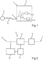
- Fig.1 shows in a greatly simplified, schematic representation a household appliance 1.
- the household appliance 1 can be a large household appliance, such as a washing machine, a tumble dryer, a dishwasher, a cooking appliance, an extractor hood or a refrigeration device, such as a refrigerator, a freezer or a fridge-freezer be.
- the household appliance 1 can also be a small household appliance, such as a water heater, a fully automatic coffee machine, a food processor or a vacuum cleaner.
- the household appliance 1 comprises a line filter device 2 which is arranged within a housing 3 of the household appliance 1.
- the line filter device 2 comprises an input 4 which can be electrically connected to a power supply 5.
- the power supply 5, which is only shown schematically in the present case, can be assigned to a house or building in which the household appliance 1 is located.
- An electrical voltage or mains voltage can be provided by the power supply 5. This mains voltage can be 230 V, for example.
- the input 4 of the line filter device 2 can be electrically connected to the power supply 5 by means of a mains connection 6 or mains plug.
- the line filter device 2 includes an output 7, which is electrically connected to electrical components 8 of the household appliance 1.
- the electrical components 8 can be electrical drives, control devices, computing devices or the like.
- the electrical components 8 are arranged in the housing 3 of the household appliance 1. Two electrical components 8 are shown here by way of example. These electrical components 8 generate electromagnetic interference when the household appliance 1 is in operation. These electromagnetic interference can be filtered by means of the line filter device 2. In this way it can be prevented that the disturbances are fed into the power supply 5.
- Fig. 2 shows the line filter device 2 according to a first embodiment in a schematic representation.
- the line filter device 2 comprises a filter device 9, which has at least one capacitor. It can also be provided that the filter device 9 has a plurality of capacitors. Furthermore, the filter device 9 can have a filter network made up of capacitors and coils. It is provided that the at least one capacitor is connected between a connection, which is assigned to an outer conductor of the power supply 5, and a connection, which is assigned to a neutral conductor of the power supply 5.
- the electromagnetic interference of the electrical components can be filtered by means of the filter device 9 of the line filter device 2.
- the filtered signal is thus present at the input 4 of the line filter device 2.
- the line filter device 2 comprises a switching device 10.
- the switching device 10 is arranged between the input 4 and the filter device 9.
- the electrical connection between the filter device 9 and the input 4 can be switched by means of the switching device 10.
- the switching device 10 can have a relay.
- the line filter device 2 comprises a measuring device 12 by means of which the electrical voltage at the input 4 can be measured.
- the current voltage at input 4 can thus be determined.
- the measuring device 12 can correspondingly sample the electrical voltage at the input and transmit it to the control device 11 in digital form.
- the control device 11 can compare the measured voltage with corresponding setpoint values and thus check whether the mains voltage is present at the input. If there is no electrical voltage at the input 4 and the frequency of the voltage does not correspond to a setpoint frequency or the frequency of the mains voltage, the control device 11 can recognize that the mains connection 6 has been disconnected from the power supply 5. In this case, the control device 11 can control the switching device 10 in such a way that the electrical connection between the filter device 9 and the input 4 is disconnected. The switching device 10 is therefore opened here. When the network connection 6 is connected to the power supply 5, the switching device 10 remains closed. Thus, electromagnetic interference can be prevented from being transmitted from the electrical components 8 to the power supply 5.
- Fig. 3 shows the line filter device 2 according to a second embodiment in a schematic representation.
- the control device 11 is also designed to determine a current operating state of the household appliance 1 to capture. If the household appliance 1 is in an activated operating state, the control device 11 can control the switching device 10 such that it is closed and the filter device 9 is thus connected to the input 4. If, however, the household appliance 1 is in a switched-off state or in an idle state, the control device 11 can control the switching device 10 such that it is open and the filter device 9 is thus electrically isolated from the input 4. Energy can thus be saved.
- the line filter device 2 comprises in comparison to the line filter device 2 according to FIG Fig. 2 an energy supply device 13 instead of the measuring device 12. This energy supply device 13 serves to supply the control device 11 with electrical energy, even when the switching device 10 is open.
Landscapes
- Physics & Mathematics (AREA)
- Electromagnetism (AREA)
- Engineering & Computer Science (AREA)
- Power Engineering (AREA)
- Remote Monitoring And Control Of Power-Distribution Networks (AREA)
- Details Of Connecting Devices For Male And Female Coupling (AREA)
Applications Claiming Priority (1)
| Application Number | Priority Date | Filing Date | Title |
|---|---|---|---|
| DE102019205623.7A DE102019205623A1 (de) | 2019-04-17 | 2019-04-17 | Netzfiltervorrichtung für ein Haushaltsgerät, Haushaltsgerät sowie Verfahren |
Publications (2)
| Publication Number | Publication Date |
|---|---|
| EP3726714A2 true EP3726714A2 (fr) | 2020-10-21 |
| EP3726714A3 EP3726714A3 (fr) | 2020-10-28 |
Family
ID=70277223
Family Applications (1)
| Application Number | Title | Priority Date | Filing Date |
|---|---|---|---|
| EP20168772.0A Pending EP3726714A3 (fr) | 2019-04-17 | 2020-04-08 | Dispositif de filtre d'alimentation pour un appareil électroménager, appareil électroménager ainsi que procédé |
Country Status (2)
| Country | Link |
|---|---|
| EP (1) | EP3726714A3 (fr) |
| DE (1) | DE102019205623A1 (fr) |
Families Citing this family (1)
| Publication number | Priority date | Publication date | Assignee | Title |
|---|---|---|---|---|
| DE102022211760A1 (de) | 2022-11-08 | 2024-05-08 | Fronius International Gmbh | Verfahren und Vorrichtung zum Erkennen eines Netzleitungsdefektes |
Citations (1)
| Publication number | Priority date | Publication date | Assignee | Title |
|---|---|---|---|---|
| EP2584687A2 (fr) | 2011-10-21 | 2013-04-24 | Samsung Electronics Co., Ltd. | Système d'alimentation électrique et appareil de formation d'image comprenant le système d'alimentation électrique |
Family Cites Families (4)
| Publication number | Priority date | Publication date | Assignee | Title |
|---|---|---|---|---|
| JP2003070159A (ja) * | 2001-06-01 | 2003-03-07 | Sharp Corp | 電源制御回路及び調理器 |
| DE102009045968A1 (de) * | 2009-10-23 | 2011-05-05 | BSH Bosch und Siemens Hausgeräte GmbH | Haushaltsgerät und Verfahren zum Betreiben eines Haushaltsgeräts |
| ITTO20101001A1 (it) * | 2010-12-16 | 2012-06-17 | Indesit Co Spa | Circuiteria elettronica per elettrodomestici |
| WO2012160695A1 (fr) * | 2011-05-26 | 2012-11-29 | Necディスプレイソリューションズ株式会社 | Fiche d'alimentation électrique, et dispositif électronique le comportant |
-
2019
- 2019-04-17 DE DE102019205623.7A patent/DE102019205623A1/de active Pending
-
2020
- 2020-04-08 EP EP20168772.0A patent/EP3726714A3/fr active Pending
Patent Citations (1)
| Publication number | Priority date | Publication date | Assignee | Title |
|---|---|---|---|---|
| EP2584687A2 (fr) | 2011-10-21 | 2013-04-24 | Samsung Electronics Co., Ltd. | Système d'alimentation électrique et appareil de formation d'image comprenant le système d'alimentation électrique |
Also Published As
| Publication number | Publication date |
|---|---|
| DE102019205623A1 (de) | 2020-10-22 |
| EP3726714A3 (fr) | 2020-10-28 |
Similar Documents
| Publication | Publication Date | Title |
|---|---|---|
| EP2217754B1 (fr) | Circuits pour faire fonctionner un appareil électroménager | |
| WO2011107256A2 (fr) | Appareil électrique comportant un circuit de condensateur d'antiparasitage | |
| DE60219240T2 (de) | Steuerungsschaltung für Stromversorgung und Kochvorrichtung | |
| EP3726714A2 (fr) | Dispositif de filtre d'alimentation pour un appareil électroménager, appareil électroménager ainsi que procédé | |
| EP2315337B1 (fr) | Appareil ménager et procédé de fonctionnement d'un appareil ménager | |
| EP2315338B1 (fr) | Agencement de commutation (à l'arrêt) destiné au fonctionnement d'un appareil ménager et procédé correspondant | |
| EP2539912B1 (fr) | Configuration de circuit pour faire fonctionner un appareil électroménager, et procédé correspondant | |
| EP2484007B1 (fr) | Procédé de fonctionnement d'un appareil électroménager et appareil électroménager pour la mise en oeuvre de ce procédé | |
| DE102010002877B4 (de) | Verfahren zum Betreiben eines Haushaltsgeräts und Haushaltsgerät | |
| EP2959048B1 (fr) | Appareil ménager, en particulier sèche-linge, doté d'un moteur à courant continu sans balais et procédé pour faire fonctionner un moteur à courant continu sans balais dans un appareil ménager | |
| DE102010031020B4 (de) | Haushaltsgerät und Verfahren zum Überprüfen eines elektrischen Verbrauchers eines Haushaltsgerätes | |
| DE102010009990A1 (de) | Elektrisches Gerät mit geringer Leistungsaufnahme im Betriebsbereitschafts-Zustand | |
| DE102010028569A1 (de) | Haushaltsgerät und Verfahren zum Betreiben eines Haushaltsgerätes | |
| DE102019204528A1 (de) | Haushaltsgerät mit einer elektrischen Funktionseinheit sowie Verfahren zu deren Betrieb | |
| DE102009010409B4 (de) | Steuervorrichtung | |
| DE102010038485A1 (de) | Schaltung und Verfahren zum Betreiben eines Hausgeräts sowie Hausgerät | |
| DE10218863A1 (de) | Hausgerät und Vorrichtung zum Einbau in ein Hausgerät | |
| DE102009028954A1 (de) | Elektrisches Netzfilter für ein Haushaltsgerät, Haushaltsgerät und Verfahren zum Betreiben eines elektrischen Netzfilters | |
| EP2684276B1 (fr) | Appareil ménager ayant un mode de veille ainsi que procédé pour faire fonctionner un tel appareil ménager | |
| DE102019219014A1 (de) | Wasserführendes Haushaltsgerät und Verfahren zum Betreiben eines wasserführenden Haushaltsgeräts | |
| WO2012025371A1 (fr) | Circuit permettant de faire fonctionner un appareil ménager, module à bouton-poussoir pour un appareil ménager et procédé permettant de faire fonctionner un appareil ménager | |
| EP2434516A1 (fr) | Circuit électrique pour le fonctionnement d'un appareil ménager | |
| DE102010031021A1 (de) | Haushaltsgerät und Verfahren zum Erkennen eines Erdschlussfalls, insbesondere Wassereintritts in einen Behälter | |
| WO2013030156A2 (fr) | Appareil ménager comprenant une circuiterie électrique ayant un mode de veille et un mode de fonctionnement ainsi que procédé pour faire fonctionner une circuiterie d'un appareil ménager | |
| EP2312702A1 (fr) | Prise d'alimentation pour un appareil ménager, appareil ménager et procédé pour brancher et débrancher un composant agencé dans un appareil ménager à l'aide d'un commutateur |
Legal Events
| Date | Code | Title | Description |
|---|---|---|---|
| PUAI | Public reference made under article 153(3) epc to a published international application that has entered the european phase |
Free format text: ORIGINAL CODE: 0009012 |
|
| STAA | Information on the status of an ep patent application or granted ep patent |
Free format text: STATUS: THE APPLICATION HAS BEEN PUBLISHED |
|
| PUAL | Search report despatched |
Free format text: ORIGINAL CODE: 0009013 |
|
| AK | Designated contracting states |
Kind code of ref document: A2 Designated state(s): AL AT BE BG CH CY CZ DE DK EE ES FI FR GB GR HR HU IE IS IT LI LT LU LV MC MK MT NL NO PL PT RO RS SE SI SK SM TR |
|
| AX | Request for extension of the european patent |
Extension state: BA ME |
|
| AK | Designated contracting states |
Kind code of ref document: A3 Designated state(s): AL AT BE BG CH CY CZ DE DK EE ES FI FR GB GR HR HU IE IS IT LI LT LU LV MC MK MT NL NO PL PT RO RS SE SI SK SM TR |
|
| AX | Request for extension of the european patent |
Extension state: BA ME |
|
| RIC1 | Information provided on ipc code assigned before grant |
Ipc: H02M 1/44 20070101AFI20200922BHEP |
|
| STAA | Information on the status of an ep patent application or granted ep patent |
Free format text: STATUS: REQUEST FOR EXAMINATION WAS MADE |
|
| 17P | Request for examination filed |
Effective date: 20210428 |
|
| RBV | Designated contracting states (corrected) |
Designated state(s): AL AT BE BG CH CY CZ DE DK EE ES FI FR GB GR HR HU IE IS IT LI LT LU LV MC MK MT NL NO PL PT RO RS SE SI SK SM TR |
|
| GRAP | Despatch of communication of intention to grant a patent |
Free format text: ORIGINAL CODE: EPIDOSNIGR1 |
|
| STAA | Information on the status of an ep patent application or granted ep patent |
Free format text: STATUS: GRANT OF PATENT IS INTENDED |