EP3726659B1 - Electrical connecting device and vehicle and charger using the same - Google Patents
Electrical connecting device and vehicle and charger using the same Download PDFInfo
- Publication number
- EP3726659B1 EP3726659B1 EP19218656.7A EP19218656A EP3726659B1 EP 3726659 B1 EP3726659 B1 EP 3726659B1 EP 19218656 A EP19218656 A EP 19218656A EP 3726659 B1 EP3726659 B1 EP 3726659B1
- Authority
- EP
- European Patent Office
- Prior art keywords
- locking member
- connecting device
- base
- linkage
- electrical connecting
- Prior art date
- Legal status (The legal status is an assumption and is not a legal conclusion. Google has not performed a legal analysis and makes no representation as to the accuracy of the status listed.)
- Active
Links
Images





Classifications
-
- H—ELECTRICITY
- H01—ELECTRIC ELEMENTS
- H01R—ELECTRICALLY-CONDUCTIVE CONNECTIONS; STRUCTURAL ASSOCIATIONS OF A PLURALITY OF MUTUALLY-INSULATED ELECTRICAL CONNECTING ELEMENTS; COUPLING DEVICES; CURRENT COLLECTORS
- H01R35/00—Flexible or turnable line connectors, i.e. the rotation angle being limited
- H01R35/02—Flexible line connectors without frictional contact members
-
- H—ELECTRICITY
- H01—ELECTRIC ELEMENTS
- H01R—ELECTRICALLY-CONDUCTIVE CONNECTIONS; STRUCTURAL ASSOCIATIONS OF A PLURALITY OF MUTUALLY-INSULATED ELECTRICAL CONNECTING ELEMENTS; COUPLING DEVICES; CURRENT COLLECTORS
- H01R13/00—Details of coupling devices of the kinds covered by groups H01R12/70 or H01R24/00 - H01R33/00
- H01R13/46—Bases; Cases
- H01R13/502—Bases; Cases composed of different pieces
-
- H—ELECTRICITY
- H01—ELECTRIC ELEMENTS
- H01R—ELECTRICALLY-CONDUCTIVE CONNECTIONS; STRUCTURAL ASSOCIATIONS OF A PLURALITY OF MUTUALLY-INSULATED ELECTRICAL CONNECTING ELEMENTS; COUPLING DEVICES; CURRENT COLLECTORS
- H01R13/00—Details of coupling devices of the kinds covered by groups H01R12/70 or H01R24/00 - H01R33/00
- H01R13/62—Means for facilitating engagement or disengagement of coupling parts or for holding them in engagement
- H01R13/629—Additional means for facilitating engagement or disengagement of coupling parts, e.g. aligning or guiding means, levers, gas pressure electrical locking indicators, manufacturing tolerances
-
- B—PERFORMING OPERATIONS; TRANSPORTING
- B60—VEHICLES IN GENERAL
- B60L—PROPULSION OF ELECTRICALLY-PROPELLED VEHICLES; SUPPLYING ELECTRIC POWER FOR AUXILIARY EQUIPMENT OF ELECTRICALLY-PROPELLED VEHICLES; ELECTRODYNAMIC BRAKE SYSTEMS FOR VEHICLES IN GENERAL; MAGNETIC SUSPENSION OR LEVITATION FOR VEHICLES; MONITORING OPERATING VARIABLES OF ELECTRICALLY-PROPELLED VEHICLES; ELECTRIC SAFETY DEVICES FOR ELECTRICALLY-PROPELLED VEHICLES
- B60L50/00—Electric propulsion with power supplied within the vehicle
- B60L50/50—Electric propulsion with power supplied within the vehicle using propulsion power supplied by batteries or fuel cells
- B60L50/60—Electric propulsion with power supplied within the vehicle using propulsion power supplied by batteries or fuel cells using power supplied by batteries
- B60L50/64—Constructional details of batteries specially adapted for electric vehicles
-
- B—PERFORMING OPERATIONS; TRANSPORTING
- B60—VEHICLES IN GENERAL
- B60L—PROPULSION OF ELECTRICALLY-PROPELLED VEHICLES; SUPPLYING ELECTRIC POWER FOR AUXILIARY EQUIPMENT OF ELECTRICALLY-PROPELLED VEHICLES; ELECTRODYNAMIC BRAKE SYSTEMS FOR VEHICLES IN GENERAL; MAGNETIC SUSPENSION OR LEVITATION FOR VEHICLES; MONITORING OPERATING VARIABLES OF ELECTRICALLY-PROPELLED VEHICLES; ELECTRIC SAFETY DEVICES FOR ELECTRICALLY-PROPELLED VEHICLES
- B60L50/00—Electric propulsion with power supplied within the vehicle
- B60L50/50—Electric propulsion with power supplied within the vehicle using propulsion power supplied by batteries or fuel cells
- B60L50/60—Electric propulsion with power supplied within the vehicle using propulsion power supplied by batteries or fuel cells using power supplied by batteries
- B60L50/66—Arrangements of batteries
-
- B—PERFORMING OPERATIONS; TRANSPORTING
- B60—VEHICLES IN GENERAL
- B60L—PROPULSION OF ELECTRICALLY-PROPELLED VEHICLES; SUPPLYING ELECTRIC POWER FOR AUXILIARY EQUIPMENT OF ELECTRICALLY-PROPELLED VEHICLES; ELECTRODYNAMIC BRAKE SYSTEMS FOR VEHICLES IN GENERAL; MAGNETIC SUSPENSION OR LEVITATION FOR VEHICLES; MONITORING OPERATING VARIABLES OF ELECTRICALLY-PROPELLED VEHICLES; ELECTRIC SAFETY DEVICES FOR ELECTRICALLY-PROPELLED VEHICLES
- B60L53/00—Methods of charging batteries, specially adapted for electric vehicles; Charging stations or on-board charging equipment therefor; Exchange of energy storage elements in electric vehicles
- B60L53/10—Methods of charging batteries, specially adapted for electric vehicles; Charging stations or on-board charging equipment therefor; Exchange of energy storage elements in electric vehicles characterised by the energy transfer between the charging station and the vehicle
- B60L53/14—Conductive energy transfer
- B60L53/16—Connectors, e.g. plugs or sockets, specially adapted for charging electric vehicles
-
- B—PERFORMING OPERATIONS; TRANSPORTING
- B60—VEHICLES IN GENERAL
- B60L—PROPULSION OF ELECTRICALLY-PROPELLED VEHICLES; SUPPLYING ELECTRIC POWER FOR AUXILIARY EQUIPMENT OF ELECTRICALLY-PROPELLED VEHICLES; ELECTRODYNAMIC BRAKE SYSTEMS FOR VEHICLES IN GENERAL; MAGNETIC SUSPENSION OR LEVITATION FOR VEHICLES; MONITORING OPERATING VARIABLES OF ELECTRICALLY-PROPELLED VEHICLES; ELECTRIC SAFETY DEVICES FOR ELECTRICALLY-PROPELLED VEHICLES
- B60L53/00—Methods of charging batteries, specially adapted for electric vehicles; Charging stations or on-board charging equipment therefor; Exchange of energy storage elements in electric vehicles
- B60L53/80—Exchanging energy storage elements, e.g. removable batteries
-
- B—PERFORMING OPERATIONS; TRANSPORTING
- B62—LAND VEHICLES FOR TRAVELLING OTHERWISE THAN ON RAILS
- B62J—CYCLE SADDLES OR SEATS; AUXILIARY DEVICES OR ACCESSORIES SPECIALLY ADAPTED TO CYCLES AND NOT OTHERWISE PROVIDED FOR, e.g. ARTICLE CARRIERS OR CYCLE PROTECTORS
- B62J99/00—Subject matter not provided for in other groups of this subclass
-
- H—ELECTRICITY
- H01—ELECTRIC ELEMENTS
- H01R—ELECTRICALLY-CONDUCTIVE CONNECTIONS; STRUCTURAL ASSOCIATIONS OF A PLURALITY OF MUTUALLY-INSULATED ELECTRICAL CONNECTING ELEMENTS; COUPLING DEVICES; CURRENT COLLECTORS
- H01R13/00—Details of coupling devices of the kinds covered by groups H01R12/70 or H01R24/00 - H01R33/00
- H01R13/02—Contact members
- H01R13/22—Contacts for co-operating by abutting
- H01R13/24—Contacts for co-operating by abutting resilient; resiliently-mounted
-
- H—ELECTRICITY
- H01—ELECTRIC ELEMENTS
- H01R—ELECTRICALLY-CONDUCTIVE CONNECTIONS; STRUCTURAL ASSOCIATIONS OF A PLURALITY OF MUTUALLY-INSULATED ELECTRICAL CONNECTING ELEMENTS; COUPLING DEVICES; CURRENT COLLECTORS
- H01R13/00—Details of coupling devices of the kinds covered by groups H01R12/70 or H01R24/00 - H01R33/00
- H01R13/40—Securing contact members in or to a base or case; Insulating of contact members
- H01R13/42—Securing in a demountable manner
- H01R13/428—Securing in a demountable manner by resilient locking means on the contact members; by locking means on resilient contact members
-
- H—ELECTRICITY
- H01—ELECTRIC ELEMENTS
- H01R—ELECTRICALLY-CONDUCTIVE CONNECTIONS; STRUCTURAL ASSOCIATIONS OF A PLURALITY OF MUTUALLY-INSULATED ELECTRICAL CONNECTING ELEMENTS; COUPLING DEVICES; CURRENT COLLECTORS
- H01R13/00—Details of coupling devices of the kinds covered by groups H01R12/70 or H01R24/00 - H01R33/00
- H01R13/62—Means for facilitating engagement or disengagement of coupling parts or for holding them in engagement
- H01R13/625—Casing or ring with bayonet engagement
-
- H—ELECTRICITY
- H01—ELECTRIC ELEMENTS
- H01R—ELECTRICALLY-CONDUCTIVE CONNECTIONS; STRUCTURAL ASSOCIATIONS OF A PLURALITY OF MUTUALLY-INSULATED ELECTRICAL CONNECTING ELEMENTS; COUPLING DEVICES; CURRENT COLLECTORS
- H01R13/00—Details of coupling devices of the kinds covered by groups H01R12/70 or H01R24/00 - H01R33/00
- H01R13/62—Means for facilitating engagement or disengagement of coupling parts or for holding them in engagement
- H01R13/627—Snap or like fastening
-
- H—ELECTRICITY
- H01—ELECTRIC ELEMENTS
- H01R—ELECTRICALLY-CONDUCTIVE CONNECTIONS; STRUCTURAL ASSOCIATIONS OF A PLURALITY OF MUTUALLY-INSULATED ELECTRICAL CONNECTING ELEMENTS; COUPLING DEVICES; CURRENT COLLECTORS
- H01R13/00—Details of coupling devices of the kinds covered by groups H01R12/70 or H01R24/00 - H01R33/00
- H01R13/62—Means for facilitating engagement or disengagement of coupling parts or for holding them in engagement
- H01R13/639—Additional means for holding or locking coupling parts together, after engagement, e.g. separate keylock, retainer strap
-
- H—ELECTRICITY
- H01—ELECTRIC ELEMENTS
- H01R—ELECTRICALLY-CONDUCTIVE CONNECTIONS; STRUCTURAL ASSOCIATIONS OF A PLURALITY OF MUTUALLY-INSULATED ELECTRICAL CONNECTING ELEMENTS; COUPLING DEVICES; CURRENT COLLECTORS
- H01R13/00—Details of coupling devices of the kinds covered by groups H01R12/70 or H01R24/00 - H01R33/00
- H01R13/64—Means for preventing incorrect coupling
- H01R13/641—Means for preventing incorrect coupling by indicating incorrect coupling; by indicating correct or full engagement
-
- H—ELECTRICITY
- H01—ELECTRIC ELEMENTS
- H01R—ELECTRICALLY-CONDUCTIVE CONNECTIONS; STRUCTURAL ASSOCIATIONS OF A PLURALITY OF MUTUALLY-INSULATED ELECTRICAL CONNECTING ELEMENTS; COUPLING DEVICES; CURRENT COLLECTORS
- H01R31/00—Coupling parts supported only by co-operation with counterpart
- H01R31/06—Intermediate parts for linking two coupling parts, e.g. adapter
-
- H—ELECTRICITY
- H02—GENERATION; CONVERSION OR DISTRIBUTION OF ELECTRIC POWER
- H02G—INSTALLATION OF ELECTRIC CABLES OR LINES, OR OF COMBINED OPTICAL AND ELECTRIC CABLES OR LINES
- H02G11/00—Arrangements of electric cables or lines between relatively-movable parts
- H02G11/02—Arrangements of electric cables or lines between relatively-movable parts using take-up reel or drum
-
- H—ELECTRICITY
- H02—GENERATION; CONVERSION OR DISTRIBUTION OF ELECTRIC POWER
- H02J—ELECTRIC POWER NETWORKS; CIRCUIT ARRANGEMENTS OR SYSTEMS FOR SUPPLYING OR DISTRIBUTING ELECTRIC POWER; SYSTEMS FOR STORING ELECTRIC ENERGY
- H02J7/00—Circuit arrangements for charging or discharging batteries or for supplying loads from batteries
- H02J7/70—Circuit arrangements for charging or discharging batteries or for supplying loads from batteries characterised by the mechanical construction
-
- B—PERFORMING OPERATIONS; TRANSPORTING
- B60—VEHICLES IN GENERAL
- B60L—PROPULSION OF ELECTRICALLY-PROPELLED VEHICLES; SUPPLYING ELECTRIC POWER FOR AUXILIARY EQUIPMENT OF ELECTRICALLY-PROPELLED VEHICLES; ELECTRODYNAMIC BRAKE SYSTEMS FOR VEHICLES IN GENERAL; MAGNETIC SUSPENSION OR LEVITATION FOR VEHICLES; MONITORING OPERATING VARIABLES OF ELECTRICALLY-PROPELLED VEHICLES; ELECTRIC SAFETY DEVICES FOR ELECTRICALLY-PROPELLED VEHICLES
- B60L2200/00—Type of vehicles
- B60L2200/12—Bikes
-
- H—ELECTRICITY
- H01—ELECTRIC ELEMENTS
- H01R—ELECTRICALLY-CONDUCTIVE CONNECTIONS; STRUCTURAL ASSOCIATIONS OF A PLURALITY OF MUTUALLY-INSULATED ELECTRICAL CONNECTING ELEMENTS; COUPLING DEVICES; CURRENT COLLECTORS
- H01R2201/00—Connectors or connections adapted for particular applications
- H01R2201/26—Connectors or connections adapted for particular applications for vehicles
-
- Y—GENERAL TAGGING OF NEW TECHNOLOGICAL DEVELOPMENTS; GENERAL TAGGING OF CROSS-SECTIONAL TECHNOLOGIES SPANNING OVER SEVERAL SECTIONS OF THE IPC; TECHNICAL SUBJECTS COVERED BY FORMER USPC CROSS-REFERENCE ART COLLECTIONS [XRACs] AND DIGESTS
- Y02—TECHNOLOGIES OR APPLICATIONS FOR MITIGATION OR ADAPTATION AGAINST CLIMATE CHANGE
- Y02T—CLIMATE CHANGE MITIGATION TECHNOLOGIES RELATED TO TRANSPORTATION
- Y02T10/00—Road transport of goods or passengers
- Y02T10/60—Other road transportation technologies with climate change mitigation effect
- Y02T10/70—Energy storage systems for electromobility, e.g. batteries
-
- Y—GENERAL TAGGING OF NEW TECHNOLOGICAL DEVELOPMENTS; GENERAL TAGGING OF CROSS-SECTIONAL TECHNOLOGIES SPANNING OVER SEVERAL SECTIONS OF THE IPC; TECHNICAL SUBJECTS COVERED BY FORMER USPC CROSS-REFERENCE ART COLLECTIONS [XRACs] AND DIGESTS
- Y02—TECHNOLOGIES OR APPLICATIONS FOR MITIGATION OR ADAPTATION AGAINST CLIMATE CHANGE
- Y02T—CLIMATE CHANGE MITIGATION TECHNOLOGIES RELATED TO TRANSPORTATION
- Y02T10/00—Road transport of goods or passengers
- Y02T10/60—Other road transportation technologies with climate change mitigation effect
- Y02T10/7072—Electromobility specific charging systems or methods for batteries, ultracapacitors, supercapacitors or double-layer capacitors
-
- Y—GENERAL TAGGING OF NEW TECHNOLOGICAL DEVELOPMENTS; GENERAL TAGGING OF CROSS-SECTIONAL TECHNOLOGIES SPANNING OVER SEVERAL SECTIONS OF THE IPC; TECHNICAL SUBJECTS COVERED BY FORMER USPC CROSS-REFERENCE ART COLLECTIONS [XRACs] AND DIGESTS
- Y02—TECHNOLOGIES OR APPLICATIONS FOR MITIGATION OR ADAPTATION AGAINST CLIMATE CHANGE
- Y02T—CLIMATE CHANGE MITIGATION TECHNOLOGIES RELATED TO TRANSPORTATION
- Y02T90/00—Enabling technologies or technologies with a potential or indirect contribution to GHG emissions mitigation
- Y02T90/10—Technologies relating to charging of electric vehicles
- Y02T90/14—Plug-in electric vehicles
Definitions
- the present disclosure relates to a connecting device, and more particularly, to an electrical connecting device used in a vehicle or a charger.
- Batteries such as lithium-ion batteries are known for storing more energy into smaller and lighter units.
- Various applications have been found for lithium ion batteries, more particularly, applications in powering portable electronic devices such as cell phones, tablets, laptops, power tools, and other high-current equipment.
- Characteristics such as low weight and high energy density of lithium-ion batteries also make it one of the best candidates for use in hybrid electric vehicles and fully electric-powered vehicles.
- the designs may relate to minimizing the likelihood of installing a battery pack in an orientation within a device to be powered by the battery pack or within a device for charging the battery pack. As such, the electrical power does not flow between the two or does flow, but creates unsafe consequences.
- an electrical connecting device as defined by independent claim 1 is provided.
- the remaining independent claims define a vehicle and a charger, respectively.
- the dependent claims show some examples for such an electrical connecting device.
- the disclosure provides an electrical connecting device capable of efficiently solving the aforementioned problems.
- an electrical connecting device includes a base, a locking member, linkage, and a detector.
- the locking member is rotatably disposed on the base and configured to rotate about an axis to a locked position along a first rotational direction and to an unlocked position along a second rotational direction opposite to the first rotational direction.
- An engaging portion is provided at a peripheral edge of the locking member.
- the linkage is rotatably disposed on the base and includes an abutting portion configured to abut against the peripheral edge. When the locking member is rotated to the locked position, the abutting portion is moved to and is engaged with the engaging portion accompanied with a rotation of the linkage.
- the detector is disposed on the base and configured to detect the engagement between the abutting portion and the engaging portion.
- the connecting device further includes an actuation module.
- the actuation module is disposed on the base and includes a moving member. The actuation module is configured to rotate the linkage through the moving member so the abutting portion is disengaged from the engaging portion.
- the actuation module further includes a resilient member.
- the resilient member is configured to apply a force to the linkage through the moving member, such that the abutting portion is continuously abutted against the peripheral edge.
- the moving member has a pushing portion configured to push the locking member to rotate along the second rotational direction after the abutting portion is disengaged from the engaging portion.
- the connecting device further includes a resilient member disposed on the base.
- the resilient member is configured to apply a force to rotate the locking member along the second rotational direction.
- the resilient member is connected between the base and the locking member.
- the resilient member is connected between the linkage and the locking member.
- the connecting device further includes a connecting bar connected between the linkage and the locking member.
- one of the linkage and the locking member is rotatably and slidably connected to the connecting bar.
- Another of the linkage and the locking member is pivotally connected to the connecting bar.
- the connecting bar has a sliding chute.
- Said one of the linkage and the locking member has a protrusion rotatably and slidably engaged with the sliding chute.
- said another of the linkage and the locking member has a pivotal portion pivotally connected to the connecting bar.
- the sliding chute has two ends. Distances from the pivotal portion respectively to said two ends are different.
- the sliding chute has two ends.
- the protrusion is abutted against said two ends when the locking member is rotated to the locked position and the unlocked position, respectively.
- the connecting device further includes a stage configured to move toward and away from the base.
- the stage has a first inclined portion and a second inclined portion.
- the first inclined portion pushes the locking member to rotate along the first rotational direction when the stage is moved toward the base.
- the second inclined portion pushes the locking member to rotate along the second rotational direction when the stage is moved away from the base.
- the stage has a sliding chute.
- the first inclined portion and the second inclined portion are opposite inner edges of the sliding chute.
- the locking member has a protrusion slidably engaged with the sliding chute.
- the axis passes through the base.
- the stage is configured to move toward and away from the base along the axis.
- the connecting device further includes a retaining member disposed on the base and configured to guide the stage to move toward and away from the base.
- the locking member includes a plurality of hooks.
- the hooks surround the axis and, and each of the hooks substantially extends along the first rotational direction.
- the locking member is ring-shaped.
- a vehicle includes a housing and the connecting device.
- the base is a part of the housing.
- a charger includes a housing and the connecting device.
- the base is a part of the housing.
- the locking member is configured to lock an installed/inserted battery pack while rotating to the locked position.
- the linkage of the connecting device is configured to keep the locking member in the locked position, thereby ensuring that the battery pack stays engaged with the connecting device.
- the linkage is designed to rotate to lock the locking member when the locking member is rotated to the locked position, and the detector of the connecting device is configured to detect the rotation of the linkage. As such, by determining whether the locking member is rotated to the locked position (through detecting the rotation of the linkage), whether the battery pack is properly installed/inserted to connect the connecting device can be determined.
- Fig. 1 is a side view of a vehicle 100 according to some embodiments of the disclosure.
- the vehicle 100 e.g., a straddle-type vehicle
- the vehicle 100 includes a housing 110 and an electrical connecting device 200.
- the housing 110 has an accommodating space 111 therein, and the connecting device 200 is disposed in the accommodating space 111 of the housing 110.
- the accommodating space 111 serves as a battery bay for accommodating a battery pack
- the connecting device 200 is configured to establish an electrical connection between the power system of the vehicle 100 and the battery pack.
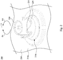
- Fig. 2 is a perspective view of the connecting device 200 according to some embodiments of the disclosure.
- the connecting device 200 includes a base 210, a connector 220, and a locking member 230.
- the base 210 is a part of the housing 110 of the vehicle 100.
- the base 210 has a first surface 210a (e.g., a top surface), a second surface 210b (e.g., a bottom surface, referring to Fig. 3A ) and a through hole 210c in spatial communication with the first surface 210a and the second surface 210b.
- the connector 220 is configured to pass through the through hole 210c.
- the locking member 230 is also configured to pass through the through hole 210c and is rotatably disposed on the base 210.
- the locking member 230 is configured in such a way that it can be rotated about an axis A to a locked position (referring to Fig. 3B ) along a first rotational direction D1 and to an unlocked position (referring to Fig. 3A ) along a second rotational direction D2 opposite to the first rotational direction D1.
- the axis A is positioned through the base 210 and substantially extends through a center of the connector 220.
- the locking member 230 is ring-shaped and is positioned such that it encloses the connector 220, but the disclosure is not limited in this regard.
- the locking member 230 is formed with a plurality of hooks 231, which substantially extend along the first rotational direction D1.
- the axis A is positioned at the center of the locking member 230 and the hooks 231.
- the battery pack includes a plurality of engaging structures. After the battery pack is inserted into the accommodating space 111 for connecting the connectors 220, the engaging structures are engaged with the hooks 231 when the locking member 230 is rotated to the locked position.
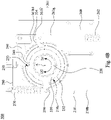
- Fig. 3A is a bottom view of the connecting device 200 shown in Fig. 2 according to some embodiments of the disclosure, in which the locking member 230 is at the unlocked position.
- Fig. 3B is another bottom view of the connecting device 200 shown in Fig. 3A according to some embodiments of the disclosure, in which the locking member 230 is at a locked position.
- the locking member 230 is formed with an engaging portion 233 at a peripheral edge 232 thereof.
- the connecting device 200 further includes a linkage 240.
- the linkage 240 is rotatably disposed on the base 210 and includes an abutting portion 241 configured to abut against the peripheral edge 232 of the locking member 230.
- the abutting portion 241 is moved along the peripheral edge 232 and is engaged with the engaging portion 233 of the locking member 230.
- the locking member 230 can be kept in the locked position by the linkage 240, thereby ensuring that the battery pack does not disengage from the connecting device 200.
- structures of the engaging portion 233 of the locking member 230 and the abutting portion 241 of the linkage 240 are interchangeable.
- the connecting device 200 further includes a detector 250 and a fixing member 280.
- the fixing member 280 is disposed on the second surface 210b of the base 210.
- the detector 250 is disposed on the base 210 via the fixing member 280 and is configured to detect the position of the engaging portion 233. More particularly, whether the locking member 230 is at the locked position can be determined by the detection results regarding the position of the engaging portion 233.
- the detector 250 is a photointerrupter which consists of a light emitting element and a light receiving element aligned facing each other in a single package. In some embodiments, the detector 250 works by detecting light transmission between the light emitting element and the light receiving element when the linkage 240 leaves the gap formed between the light emitting element and the light receiving element.
- the linkage 240 when the abutting portion 241 is disengaged from the engaging portion 233, the linkage 240 inserts into the gap and blocks the light transmitted between the light emitting element and the light receiving element; when the abutting portion 241 is engaged with the engaging portion 233, the linkage 240 leaves the gap and allows the light transmitted between the light emitting element and the light receiving element. That is, the detector 250 acts as an optical switch. In some other embodiments, the detector 250 is a mechanism, a reed switch, or the like.
- the connecting device 200 further includes an actuation module 260.
- the actuation module 260 is disposed on the base 210 and includes a moving member 261.
- the moving member 261 includes a driving shaft 261a and an extending bar 261b connected to an end of the driving shaft 261a.
- the actuation module 260 is configured to rotate the linkage 240 through the moving member 261. More specifically, when the linkage 240 is rotated, the abutting portion 241 can be disengaged from the engaging portion 233 of the locking member 230; consequently, the locking member 230 is unlocked by the linkage 240.
- the actuation module 260 is an electromagnetic switch, but the disclosure is not limited in this regard.
- the actuation module 260 further includes a resilient member 262 disposed therein.
- the resilient member 262 is configured to apply a force to the linkage 240 through the moving member 261, such that the abutting portion 241 of the linkage 240 is continuously abutted against the peripheral edge 232 of the locking member 230.
- the linkage 240 rotates in accordance with the force applied by the resilient member 262 through the moving member 261. In such a way, the abutting portion 241 automatically moves along the peripheral edge 232 to be engaged with the engaging portion 233 of the locking member 230.
- the resilient member 262 is a compression spring, but the disclosure is not limited in this regard.
- the connecting device 200 further includes a resilient member 270 disposed on the base 210.
- the locking member 230 further includes an extending portion 234 protruding from the peripheral edge 232 thereof.
- the resilient member 270 is connected between the fixing member 280 and the extending portion 234 of the locking member 230.
- the resilient member 270 is configured to apply a force to rotate the locking member 230 along the second rotational direction D2.
- the linkage 240 is rotated and the abutting portion 241 is disengaged from the engaging portion 233 of the locking member 230 (i.e., the locking member 230 is unlocked)
- the locking member 230 automatically rotates to the unlocked position (referring to Fig. 3A ) in accordance with the force applied by the resilient member 270. Consequently, the battery pack is automatically detached from the connector 220 and thus can be lifted and picked up by the user.
- the resilient member 270 is a tension spring, but the disclosure is not limited in this regard.
- Fig. 4A is a bottom view of a connecting device 300 according to some embodiments of the disclosure, in which a locking member 330 is at an unlocked position.
- Fig. 4B is another bottom view of the connecting device 300 shown in Fig. 4A according to some embodiments of the disclosure, in which the locking member 330 is at a locked position.
- the connecting device 300 includes a base 210, a connector 220, a locking member 330, a linkage 240, a detector 250, an actuation module 360, a resilient member 270 and a fixing member 280.
- the base 210, the connector 220, the linkage 240, the detector 250, the resilient member 270 and the fixing member 280 are identical or similar to those of the embodiments as illustrated in Figs. 3A and 3B ; therefore, descriptions of these components are the same and would not be repeated here for simplicity.
- the locking member 330 further includes another extending portion 334 protruding from the peripheral edge 232 of the locking member 330.
- the extending bar 361b of the moving member 361 of the actuation module 360 is provided with a pushing portion 361b1.
- the pushing portion 361b1 is configured to push the locking member 330 via the extending portion 334 to rotate along the second rotational direction after the abutting portion 241 of the linkage 240 is disengaged from the engaging portion 233 of the locking member 330.
- the pushing portion 361b1 may force the locking member 330 to rotate to the unlocked position (referring to Fig. 4A ) by pushing the extending portion 334.
- the above-mentioned situation in which the locking member 330 is stuck may occur when the connector 220 is malfunctioning or is jammed by a foreign substance.
- the locking member 330 can be ensured to rotate to the unlocked position by the designs of the pushing portion 361b1 on the extending bar 361b and the extending portion 334 of the locking member 330 when the resilient member 270 fails to rotate the locking member 330.
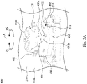
- Fig. 5A is a perspective view of a connecting device 400 according to some embodiments of the disclosure, in which a locking member 430 is at an unlocked position.
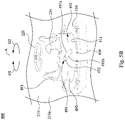
- Fig. 5B is another perspective view of the connecting device 400 shown in Fig. 5A , in which the locking member 430 is at a locked position.
- the connecting device 400 includes a base 210, a connector 220, a locking member 430, a stage 490, and a retaining member 510.
- the base 210 and the connector 220 are identical or similar to those of the embodiments as illustrated in Fig.
- the stage 490 is configured to move toward and away from the base 210 and has a sliding chute 491.
- the sliding chute 491 is inclined relative to the axis A and has a first inclined portion 491a and a second inclined portion 491b.
- the first inclined portion 491a and the second inclined portion 491b are opposite inner edges of the sliding chute 491.
- the locking member 430 has a protrusion 432 slidably engaged with the sliding chute 491. As such, the first inclined portion 491a may push the protrusion 432 to make the locking member 430 rotate along the first rotational direction A1 when the stage 490 is moved toward the base 210 (as switching from Fig. 5A to Fig.
- the second inclined portion 491b may push the protrusion 432 to make the locking member 430 rotate along the second rotational direction D2 when the stage 490 is moved away from the base 210 (as switching from Fig. 5B to Fig. 5A ).
- the stage 490 has sliding chutes 492 substantially extending along the axis A
- the retaining member 510 is disposed on the first surface 210a of the base 210 and has protrusions 511 slidably engaged with the sliding chutes 492 respectively, such that the stage 490 is ensured to move toward and away from the base 210 along the axis A with the guidance of the protrusions 511 of the retaining member 510.
- structures of the sliding chutes 492 of the stage 490 and the protrusions 511 of the retaining member 510 are interchangeable.
- the stage 490 includes supporting portions at a side of the stage 490 away from the base 210 and substantially coplanar.
- the supporting portions are configured to support at the bottom of the battery pack such that the bottom of the battery pack may avoid being scratched by the hooks 231 of the locking member 430 when the battery pack is moved toward and/or away from the connector 220 along the axis A. Accordingly, the stage 490 may improve reliability of the battery pack by preventing wear-and-tear due to abrasion.
- Fig. 6A is a bottom view of the connecting device 400 shown in Fig. 5A according to some embodiments of the disclosure.
- Fig. 6B is a bottom view of the connecting device 400 shown in Fig. 5B according to some embodiments of the disclosure.
- the connecting device 400 further includes a linkage 440, a detector 250, an actuation module 460, a resilient member 270, and a fixing member 280.
- the detector 250, the resilient member 270, and the fixing member 280 are identical or similar to those of the embodiments as illustrated in Figs.
- the resilient member 270 is connected between the extending portion the linkage 440 and the extending portion 234 of the locking member 430.
- the resilient member 270 may pull the linkage 440 to rotate and thus makes the abutting portion 241 of the linkage 440 move to and be engaged with the engaging portion 233 of the locking member 430.
- the resilient member 262 of the actuation module 260 in the embodiments as illustrated in Figs. 3A and 3B can be omitted.
- the connecting device 400 further includes a connecting bar 480 connected between the linkage 440 and the locking member 430.
- the locking member 430 is rotatably and slidably connected to the connecting bar 480.
- the linkage 440 is pivotally connected to the connecting bar 480.
- the connecting bar 480 has a sliding chute 481.
- the locking member 430 has a protrusion 431 rotatably and slidably engaged with the sliding chute 481.
- the linkage 440 has a pivotal portion 442 pivotally connected to the connecting bar 480.
- the sliding chute 481 has two ends 481a, 481b.
- a distance between the pivotal portion 442 and the ends 481a is smaller than a distance between the pivotal portion 442 and the end 481b.
- the protrusion 431 of the locking member 430 is at the end 481b of the sliding chute 481.
- the protrusion 431 of the locking member 430 is at the end 481a of the sliding chute 481.
- the end 481b of the sliding chute 481 may force the locking member 430 to rotate to the unlocked position (referring to Fig. 6A ) by pushing the protrusion 431. That is, the locking member 430 can be ensured to rotate to the unlocked position by the designs of connecting bar 480 connected between the linkage 440 and the locking member 430 when the resilient member 270 fails to rotate the locking member 430.
- the actuation module 460 omits the extending bar 261b and directly connects the linkage 440 with the driving shaft 261a. Furthermore, as shown in Figs. 6A and 6B , the detector 250 works by detecting light blockage between the light emitting element and the light receiving element when the linkage 440 comes between the light emitting element and the light receiving element.
- Fig. 7 is a top view of a charger 600 according to some embodiments of the disclosure.
- the charger 600 includes a housing 610, a power plug 620, and the connecting device 400.
- the housing 610 has a recess 611 configured to accommodating at least a part of a battery pack, and the connecting device 400 is disposed at the bottom of the recess 611.
- An end of the power plug 620 is connected to the housing 610, and the connector 220 of the connecting device 400 is electrically connected to of the power plug 620.
- the power plug 620 is configured to plug into a power outlet so as to transmit power to charge the battery pack through the connector 220.
- the connecting device 400 can be replaced by the connecting device 200 as illustrated in Figs. 3A and 3B or the connecting device 300 as illustrated in Figs. 4A and 4B .
- the locking member is configured to lock an installed/inserted battery pack while rotating to the locked position.
- the linkage of the connecting device is configured to keep the locking member in the locked position, thereby ensuring that the battery pack stay engaged with the connecting device.
- the linkage is designed to rotate to lock the locking member when the locking member is rotated to the locked position, and the detector of the connecting device is configured to detect the rotation of the linkage.
Landscapes
- Engineering & Computer Science (AREA)
- Power Engineering (AREA)
- Mechanical Engineering (AREA)
- Transportation (AREA)
- Life Sciences & Earth Sciences (AREA)
- Sustainable Development (AREA)
- Sustainable Energy (AREA)
- Charge And Discharge Circuits For Batteries Or The Like (AREA)
- Details Of Connecting Devices For Male And Female Coupling (AREA)
- Electric Propulsion And Braking For Vehicles (AREA)
- Secondary Cells (AREA)
- Battery Mounting, Suspending (AREA)
Description
- The present disclosure relates to a connecting device, and more particularly, to an electrical connecting device used in a vehicle or a charger.
- Batteries such as lithium-ion batteries are known for storing more energy into smaller and lighter units. Various applications have been found for lithium ion batteries, more particularly, applications in powering portable electronic devices such as cell phones, tablets, laptops, power tools, and other high-current equipment. Characteristics such as low weight and high energy density of lithium-ion batteries also make it one of the best candidates for use in hybrid electric vehicles and fully electric-powered vehicles.
- With the proliferation of electric powered devices (e.g., electric powered tools, appliances, personal portable communication devices, laptop and tablet computers, personal media devices, vehicles and the like), there is interest in designs of battery packs and battery pack electrical connections. For example, the designs may relate to minimizing the likelihood of installing a battery pack in an orientation within a device to be powered by the battery pack or within a device for charging the battery pack. As such, the electrical power does not flow between the two or does flow, but creates unsafe consequences.
- However, even when a battery pack is installed/inserted in a proper orientation, the electrical connection between electrical terminals of the battery pack and electrical terminals of a device to be powered by the battery pack or a device for charging the battery pack may still not operate as designed. For example, undesired conductive or nonconductive materials could be lodged between the terminals of the battery pack and the device/charger, thus resulting in the terminals being partly damaged or completely broken. Such conditions can result in unsafe consequences and degraded performance. Thus, it is an interest for the industry to develop effective ways for confirming the electrical connection between the electrical terminals of the battery pack and the electrically powered device or the device for charging the battery. Another device is known from
US 2011/171850 A1 . - Accordingly, it is an important issue for the industry to provide an electrical connecting device capable of solving the aforementioned problems.
- According to the present invention, an electrical connecting device as defined by independent claim 1 is provided. The remaining independent claims define a vehicle and a charger, respectively. The dependent claims show some examples for such an electrical connecting device. The disclosure provides an electrical connecting device capable of efficiently solving the aforementioned problems.
- According to the disclosure, an electrical connecting device includes a base, a locking member, linkage, and a detector. The locking member is rotatably disposed on the base and configured to rotate about an axis to a locked position along a first rotational direction and to an unlocked position along a second rotational direction opposite to the first rotational direction. An engaging portion is provided at a peripheral edge of the locking member. The linkage is rotatably disposed on the base and includes an abutting portion configured to abut against the peripheral edge. When the locking member is rotated to the locked position, the abutting portion is moved to and is engaged with the engaging portion accompanied with a rotation of the linkage. The detector is disposed on the base and configured to detect the engagement between the abutting portion and the engaging portion.
- In an embodiment of the disclosure, the connecting device further includes an actuation module. The actuation module is disposed on the base and includes a moving member. The actuation module is configured to rotate the linkage through the moving member so the abutting portion is disengaged from the engaging portion.
- In an embodiment of the disclosure, the actuation module further includes a resilient member. The resilient member is configured to apply a force to the linkage through the moving member, such that the abutting portion is continuously abutted against the peripheral edge.
- In an embodiment of the disclosure, the moving member has a pushing portion configured to push the locking member to rotate along the second rotational direction after the abutting portion is disengaged from the engaging portion.
- In an embodiment of the disclosure, the connecting device further includes a resilient member disposed on the base. The resilient member is configured to apply a force to rotate the locking member along the second rotational direction.
- In an embodiment of the disclosure, the resilient member is connected between the base and the locking member.
- In an embodiment of the disclosure, the resilient member is connected between the linkage and the locking member.
- In an embodiment of the disclosure, the connecting device further includes a connecting bar connected between the linkage and the locking member.
- In an embodiment of the disclosure, one of the linkage and the locking member is rotatably and slidably connected to the connecting bar. Another of the linkage and the locking member is pivotally connected to the connecting bar.
- In an embodiment of the disclosure, the connecting bar has a sliding chute. Said one of the linkage and the locking member has a protrusion rotatably and slidably engaged with the sliding chute.
- In an embodiment of the disclosure, said another of the linkage and the locking member has a pivotal portion pivotally connected to the connecting bar. The sliding chute has two ends. Distances from the pivotal portion respectively to said two ends are different.
- In an embodiment of the disclosure, the sliding chute has two ends. The protrusion is abutted against said two ends when the locking member is rotated to the locked position and the unlocked position, respectively.
- In an embodiment of the disclosure, the connecting device further includes a stage configured to move toward and away from the base. The stage has a first inclined portion and a second inclined portion. The first inclined portion pushes the locking member to rotate along the first rotational direction when the stage is moved toward the base. The second inclined portion pushes the locking member to rotate along the second rotational direction when the stage is moved away from the base.
- In an embodiment of the disclosure, the stage has a sliding chute. The first inclined portion and the second inclined portion are opposite inner edges of the sliding chute. The locking member has a protrusion slidably engaged with the sliding chute.
- In an embodiment of the disclosure, the axis passes through the base. The stage is configured to move toward and away from the base along the axis.
- In an embodiment of the disclosure, the connecting device further includes a retaining member disposed on the base and configured to guide the stage to move toward and away from the base.
- In an embodiment of the disclosure, the locking member includes a plurality of hooks. The hooks surround the axis and, and each of the hooks substantially extends along the first rotational direction.
- In an embodiment of the disclosure, the locking member is ring-shaped.
- According to another embodiment of the disclosure, a vehicle includes a housing and the connecting device. The base is a part of the housing.
- According to another embodiment of the disclosure, a charger includes a housing and the connecting device. The base is a part of the housing.
- Accordingly, in the connecting device of the disclosure, the locking member is configured to lock an installed/inserted battery pack while rotating to the locked position. The linkage of the connecting device is configured to keep the locking member in the locked position, thereby ensuring that the battery pack stays engaged with the connecting device. In addition, the linkage is designed to rotate to lock the locking member when the locking member is rotated to the locked position, and the detector of the connecting device is configured to detect the rotation of the linkage. As such, by determining whether the locking member is rotated to the locked position (through detecting the rotation of the linkage), whether the battery pack is properly installed/inserted to connect the connecting device can be determined.
- It is to be understood that both the foregoing general description and the following detailed description are by examples, and are intended to provide further explanation of the disclosure as claimed.
- The disclosure can be more fully understood by reading the following detailed description of the embodiment, with reference made to the accompanying drawings as follows:
-
Fig. 1 is a side view of a vehicle according to some embodiments of the disclosure; -
Fig. 2 is a perspective view of a connecting device according to some embodiments of the disclosure; -
Fig. 3A is a bottom view of the connecting device shown inFig. 2 according to some embodiments of the disclosure, in which a locking member is at an unlocked position; -
Fig. 3B is another bottom view of the connecting device shown inFig. 3A according to some embodiments of the disclosure, in which the locking member is at a locked position; -
Fig. 4A is a bottom view of a connecting device according to some embodiments of the disclosure, in which a locking member is at an unlocked position; -
Fig. 4B is another bottom view of the connecting device shown inFig. 4A according to some embodiments of the disclosure, in which the locking member is at a locked position; -
Fig. 5A is a perspective view of a connecting device according to some embodiments of the disclosure, in which a locking member is at an unlocked position; -
Fig. 5B is another perspective view of the connecting device shown inFig. 5A , in which the locking member is at a locked position; -
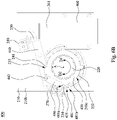
Fig. 6A is a bottom view of the connecting device shown inFig. 5A according to some embodiments of the disclosure; -
Fig. 6B is a bottom view of the connecting device shown inFig. 5B according to some embodiments of the disclosure; and -
Fig. 7 is a top view of a charger according to some embodiments of the disclosure. - Reference is made to
Fig. 1. Fig. 1 is a side view of avehicle 100 according to some embodiments of the disclosure. As shown inFig. 1 , the vehicle 100 (e.g., a straddle-type vehicle) includes ahousing 110 and an electrical connectingdevice 200. Thehousing 110 has anaccommodating space 111 therein, and the connectingdevice 200 is disposed in theaccommodating space 111 of thehousing 110. In some embodiments, theaccommodating space 111 serves as a battery bay for accommodating a battery pack, and the connectingdevice 200 is configured to establish an electrical connection between the power system of thevehicle 100 and the battery pack. - Reference is made to
Fig. 2. Fig. 2 is a perspective view of the connectingdevice 200 according to some embodiments of the disclosure. As shown inFig. 2 , the connectingdevice 200 includes abase 210, aconnector 220, and a lockingmember 230. Thebase 210 is a part of thehousing 110 of thevehicle 100. Thebase 210 has afirst surface 210a (e.g., a top surface), asecond surface 210b (e.g., a bottom surface, referring toFig. 3A ) and a throughhole 210c in spatial communication with thefirst surface 210a and thesecond surface 210b. Theconnector 220 is configured to pass through the throughhole 210c. The lockingmember 230 is also configured to pass through the throughhole 210c and is rotatably disposed on thebase 210. The lockingmember 230 is configured in such a way that it can be rotated about an axis A to a locked position (referring toFig. 3B ) along a first rotational direction D1 and to an unlocked position (referring toFig. 3A ) along a second rotational direction D2 opposite to the first rotational direction D1. - As shown in
Fig. 2 , the axis A is positioned through thebase 210 and substantially extends through a center of theconnector 220. The lockingmember 230 is ring-shaped and is positioned such that it encloses theconnector 220, but the disclosure is not limited in this regard. The lockingmember 230 is formed with a plurality ofhooks 231, which substantially extend along the first rotational direction D1. The axis A is positioned at the center of the lockingmember 230 and thehooks 231. In practical applications, the battery pack includes a plurality of engaging structures. After the battery pack is inserted into theaccommodating space 111 for connecting theconnectors 220, the engaging structures are engaged with thehooks 231 when the lockingmember 230 is rotated to the locked position. - Reference is made to
Figs. 3A and3B .Fig. 3A is a bottom view of the connectingdevice 200 shown inFig. 2 according to some embodiments of the disclosure, in which the lockingmember 230 is at the unlocked position.Fig. 3B is another bottom view of the connectingdevice 200 shown inFig. 3A according to some embodiments of the disclosure, in which the lockingmember 230 is at a locked position. As shown inFigs. 3A and3B , the lockingmember 230 is formed with an engagingportion 233 at aperipheral edge 232 thereof. The connectingdevice 200 further includes alinkage 240. Thelinkage 240 is rotatably disposed on thebase 210 and includes an abuttingportion 241 configured to abut against theperipheral edge 232 of the lockingmember 230. When the lockingmember 230 is rotated to the locked position along the first rotational direction D1 (as switching fromFig. 3A to Fig. 3B ), the abuttingportion 241 is moved along theperipheral edge 232 and is engaged with the engagingportion 233 of the lockingmember 230. As such, the lockingmember 230 can be kept in the locked position by thelinkage 240, thereby ensuring that the battery pack does not disengage from the connectingdevice 200. In practical applications, structures of the engagingportion 233 of the lockingmember 230 and the abuttingportion 241 of thelinkage 240 are interchangeable. - As shown in
Figs. 3A and3B , thelinkage 240 rotates when the abuttingportion 241 is moved along theperipheral edge 232 and is engaged with the engagingportion 233 of the locking member 230 (as switching fromFig. 3A to Fig. 3B ). The connectingdevice 200 further includes adetector 250 and a fixingmember 280. The fixingmember 280 is disposed on thesecond surface 210b of thebase 210. Thedetector 250 is disposed on thebase 210 via the fixingmember 280 and is configured to detect the position of the engagingportion 233. More particularly, whether the lockingmember 230 is at the locked position can be determined by the detection results regarding the position of the engagingportion 233. Once the position of the lockingmember 230 is known, whether the battery pack is properly installed/inserted to connect the connectingdevice 200 can be determined. In some embodiments, thedetector 250 is a photointerrupter which consists of a light emitting element and a light receiving element aligned facing each other in a single package. In some embodiments, thedetector 250 works by detecting light transmission between the light emitting element and the light receiving element when thelinkage 240 leaves the gap formed between the light emitting element and the light receiving element. Specifically, when the abuttingportion 241 is disengaged from the engagingportion 233, thelinkage 240 inserts into the gap and blocks the light transmitted between the light emitting element and the light receiving element; when the abuttingportion 241 is engaged with the engagingportion 233, thelinkage 240 leaves the gap and allows the light transmitted between the light emitting element and the light receiving element. That is, thedetector 250 acts as an optical switch. In some other embodiments, thedetector 250 is a mechanism, a reed switch, or the like. - As shown in
Figs. 3A and3B , the connectingdevice 200 further includes anactuation module 260. Theactuation module 260 is disposed on thebase 210 and includes a movingmember 261. The movingmember 261 includes a drivingshaft 261a and an extendingbar 261b connected to an end of the drivingshaft 261a. Theactuation module 260 is configured to rotate thelinkage 240 through the movingmember 261. More specifically, when thelinkage 240 is rotated, the abuttingportion 241 can be disengaged from the engagingportion 233 of the lockingmember 230; consequently, the lockingmember 230 is unlocked by thelinkage 240. In some embodiments, theactuation module 260 is an electromagnetic switch, but the disclosure is not limited in this regard. - As shown in
Figs. 3A and3B , theactuation module 260 further includes aresilient member 262 disposed therein. Theresilient member 262 is configured to apply a force to thelinkage 240 through the movingmember 261, such that the abuttingportion 241 of thelinkage 240 is continuously abutted against theperipheral edge 232 of the lockingmember 230. As such, when the lockingmember 230 is rotated to the locked position (referring toFig. 3B ), thelinkage 240 rotates in accordance with the force applied by theresilient member 262 through the movingmember 261. In such a way, the abuttingportion 241 automatically moves along theperipheral edge 232 to be engaged with the engagingportion 233 of the lockingmember 230. - In some embodiments, the
resilient member 262 is a compression spring, but the disclosure is not limited in this regard. - As shown in
Figs. 3A and3B , the connectingdevice 200 further includes aresilient member 270 disposed on thebase 210. Specifically, the lockingmember 230 further includes an extendingportion 234 protruding from theperipheral edge 232 thereof. Theresilient member 270 is connected between the fixingmember 280 and the extendingportion 234 of the lockingmember 230. Further, theresilient member 270 is configured to apply a force to rotate the lockingmember 230 along the second rotational direction D2. As such, when thelinkage 240 is rotated and the abuttingportion 241 is disengaged from the engagingportion 233 of the locking member 230 (i.e., the lockingmember 230 is unlocked), the lockingmember 230 automatically rotates to the unlocked position (referring toFig. 3A ) in accordance with the force applied by theresilient member 270. Consequently, the battery pack is automatically detached from theconnector 220 and thus can be lifted and picked up by the user. - In some embodiments, the
resilient member 270 is a tension spring, but the disclosure is not limited in this regard. - Reference is made to
Figs. 4A and4B .Fig. 4A is a bottom view of a connectingdevice 300 according to some embodiments of the disclosure, in which a lockingmember 330 is at an unlocked position.Fig. 4B is another bottom view of the connectingdevice 300 shown inFig. 4A according to some embodiments of the disclosure, in which the lockingmember 330 is at a locked position. As shown inFigs. 4A and4B , the connectingdevice 300 includes abase 210, aconnector 220, a lockingmember 330, alinkage 240, adetector 250, anactuation module 360, aresilient member 270 and a fixingmember 280. Herein, thebase 210, theconnector 220, thelinkage 240, thedetector 250, theresilient member 270 and the fixingmember 280 are identical or similar to those of the embodiments as illustrated inFigs. 3A and3B ; therefore, descriptions of these components are the same and would not be repeated here for simplicity. Compared with the embodiments as illustrated inFigs. 3A and3B , the lockingmember 330 further includes another extendingportion 334 protruding from theperipheral edge 232 of the lockingmember 330. Furthermore, the extendingbar 361b of the movingmember 361 of theactuation module 360 is provided with a pushing portion 361b1. The pushing portion 361b1 is configured to push the lockingmember 330 via the extendingportion 334 to rotate along the second rotational direction after the abuttingportion 241 of thelinkage 240 is disengaged from the engagingportion 233 of the lockingmember 330. As such, when the lockingmember 330 is stuck and cannot rotate in accordance with the force applied by theresilient member 270 after the abuttingportion 241 is disengaged from the engagingportion 233, the pushing portion 361b1 may force the lockingmember 330 to rotate to the unlocked position (referring toFig. 4A ) by pushing the extendingportion 334. The above-mentioned situation in which the lockingmember 330 is stuck may occur when theconnector 220 is malfunctioning or is jammed by a foreign substance. That is, the lockingmember 330 can be ensured to rotate to the unlocked position by the designs of the pushing portion 361b1 on the extendingbar 361b and the extendingportion 334 of the lockingmember 330 when theresilient member 270 fails to rotate the lockingmember 330. - Reference is made to
Figs. 5A and5B .Fig. 5A is a perspective view of a connectingdevice 400 according to some embodiments of the disclosure, in which a lockingmember 430 is at an unlocked position.Fig. 5B is another perspective view of the connectingdevice 400 shown inFig. 5A , in which the lockingmember 430 is at a locked position. As shown inFigs. 5A and5B , the connectingdevice 400 includes abase 210, aconnector 220, a lockingmember 430, astage 490, and a retainingmember 510. Hence, thebase 210 and theconnector 220 are identical or similar to those of the embodiments as illustrated inFig. 2 ; therefore, descriptions of these components are the same and would not be repeated here for simplicity. Thestage 490 is configured to move toward and away from thebase 210 and has a slidingchute 491. The slidingchute 491 is inclined relative to the axis A and has a firstinclined portion 491a and a secondinclined portion 491b. The firstinclined portion 491a and the secondinclined portion 491b are opposite inner edges of the slidingchute 491. The lockingmember 430 has aprotrusion 432 slidably engaged with the slidingchute 491. As such, the firstinclined portion 491a may push theprotrusion 432 to make the lockingmember 430 rotate along the first rotational direction A1 when thestage 490 is moved toward the base 210 (as switching fromFig. 5A to Fig. 5B ), and the secondinclined portion 491b may push theprotrusion 432 to make the lockingmember 430 rotate along the second rotational direction D2 when thestage 490 is moved away from the base 210 (as switching fromFig. 5B to Fig. 5A ). - As shown in
Figs. 5A and5B , thestage 490 has slidingchutes 492 substantially extending along the axis A, and the retainingmember 510 is disposed on thefirst surface 210a of thebase 210 and hasprotrusions 511 slidably engaged with the slidingchutes 492 respectively, such that thestage 490 is ensured to move toward and away from thebase 210 along the axis A with the guidance of theprotrusions 511 of the retainingmember 510. In practical applications, structures of the slidingchutes 492 of thestage 490 and theprotrusions 511 of the retainingmember 510 are interchangeable. - As shown in
Figs. 5A and5B , thestage 490 includes supporting portions at a side of thestage 490 away from thebase 210 and substantially coplanar. The supporting portions are configured to support at the bottom of the battery pack such that the bottom of the battery pack may avoid being scratched by thehooks 231 of the lockingmember 430 when the battery pack is moved toward and/or away from theconnector 220 along the axis A. Accordingly, thestage 490 may improve reliability of the battery pack by preventing wear-and-tear due to abrasion. - Reference is made to
Figs. 6A and6B .Fig. 6A is a bottom view of the connectingdevice 400 shown inFig. 5A according to some embodiments of the disclosure.Fig. 6B is a bottom view of the connectingdevice 400 shown inFig. 5B according to some embodiments of the disclosure. As shown inFigs. 6A and6B , the connectingdevice 400 further includes alinkage 440, adetector 250, anactuation module 460, aresilient member 270, and a fixingmember 280. Hence, thedetector 250, theresilient member 270, and the fixingmember 280 are identical or similar to those of the embodiments as illustrated inFigs. 3A and3B ; therefore, descriptions of these components are the same and would not be repeated here for simplicity. Compared with the embodiments as illustrated inFigs. 3A and3B , theresilient member 270 is connected between the extending portion thelinkage 440 and the extendingportion 234 of the lockingmember 430. With the structural configuration, when the lockingmember 430 is rotated to the locked position (as switching fromFig. 6A to Fig. 6B ) along the first rotational direction D1, theresilient member 270 may pull thelinkage 440 to rotate and thus makes theabutting portion 241 of thelinkage 440 move to and be engaged with the engagingportion 233 of the lockingmember 430. As such, theresilient member 262 of theactuation module 260 in the embodiments as illustrated inFigs. 3A and3B can be omitted. - As shown in
Figs. 6A and6B , the connectingdevice 400 further includes a connectingbar 480 connected between thelinkage 440 and the lockingmember 430. The lockingmember 430 is rotatably and slidably connected to the connectingbar 480. Thelinkage 440 is pivotally connected to the connectingbar 480. Specifically, the connectingbar 480 has a slidingchute 481. The lockingmember 430 has aprotrusion 431 rotatably and slidably engaged with the slidingchute 481. Thelinkage 440 has apivotal portion 442 pivotally connected to the connectingbar 480. The slidingchute 481 has twoends pivotal portion 442 and theends 481a is smaller than a distance between thepivotal portion 442 and theend 481b. As shown inFig. 6A , when the lockingmember 430 is rotated to the unlocked position, theprotrusion 431 of the lockingmember 430 is at theend 481b of the slidingchute 481. As shown inFig. 6B , when the lockingmember 430 is rotated to the locked position, theprotrusion 431 of the lockingmember 430 is at theend 481a of the slidingchute 481. As such, when the lockingmember 430 is stuck and cannot rotate in accordance with the force applied by theresilient member 270 after the abuttingportion 241 is disengaged from the engagingportion 233, theend 481b of the slidingchute 481 may force the lockingmember 430 to rotate to the unlocked position (referring toFig. 6A ) by pushing theprotrusion 431. That is, the lockingmember 430 can be ensured to rotate to the unlocked position by the designs of connectingbar 480 connected between thelinkage 440 and the lockingmember 430 when theresilient member 270 fails to rotate the lockingmember 430. - In addition, compared with the embodiments as illustrated in
Figs. 3A and3B , theactuation module 460 omits the extendingbar 261b and directly connects thelinkage 440 with the drivingshaft 261a. Furthermore, as shown inFigs. 6A and6B , thedetector 250 works by detecting light blockage between the light emitting element and the light receiving element when thelinkage 440 comes between the light emitting element and the light receiving element. - Reference is made to
Fig. 7. Fig. 7 is a top view of acharger 600 according to some embodiments of the disclosure. Thecharger 600 includes ahousing 610, apower plug 620, and the connectingdevice 400. Thehousing 610 has arecess 611 configured to accommodating at least a part of a battery pack, and the connectingdevice 400 is disposed at the bottom of therecess 611. An end of thepower plug 620 is connected to thehousing 610, and theconnector 220 of the connectingdevice 400 is electrically connected to of thepower plug 620. Thepower plug 620 is configured to plug into a power outlet so as to transmit power to charge the battery pack through theconnector 220. In some other embodiments, the connectingdevice 400 can be replaced by the connectingdevice 200 as illustrated inFigs. 3A and3B or the connectingdevice 300 as illustrated inFigs. 4A and4B . - According to the foregoing recitations of the embodiments of the disclosure, it can be seen that in the connecting device of the disclosure, the locking member is configured to lock an installed/inserted battery pack while rotating to the locked position. The linkage of the connecting device is configured to keep the locking member in the locked position, thereby ensuring that the battery pack stay engaged with the connecting device. In addition, the linkage is designed to rotate to lock the locking member when the locking member is rotated to the locked position, and the detector of the connecting device is configured to detect the rotation of the linkage. As such, by determining whether the locking member is rotated to the locked position (through detecting the rotation of the linkage), whether the battery pack is properly installed/inserted to connect the connecting device can be determined.
- Although the present disclosure has been described in considerable detail with reference to certain embodiments thereof, other embodiments are possible. Therefore, the appended claims should not be limited to the description of the embodiments contained herein.
Claims (15)
- An electrical connecting device, comprising:a base (210); a locking member (230; 330; 430) rotatably disposed on the base (210) and configured to rotate about an axis (A) to a locked position along a first rotational direction and to an unlocked position along a second rotational direction opposite to the first rotational direction (A1), wherein an engaging portion (233) is provided at a peripheral edge (232) of the locking member (230; 330; 430);a linkage (240; 440) rotatably disposed on the base (210) and comprising an abutting portion (241) configured to abut against the peripheral edge (232), wherein when the locking member (230; 330; 430) is rotated to the locked position, the abutting portion (241) is moved to and is engaged with the engaging portion (233) accompanied with a rotation of the linkage (240; 440);a detector (250) disposed on the base (210) and configured to detect the engagement between the abutting portion (241) and the engaging portion (233).
- The electrical connecting device of claim 1, further comprising:
an actuation module (260; 360; 460) disposed on the base (210) and comprising a moving member (261; 361), wherein the actuation module (260; 360; 460) is configured to rotate the linkage (240; 440) through the moving member (261; 361) so the abutting portion (241) is disengaged from the engaging portion (233). - The electrical connecting device of claim 2, wherein the actuation module (260; 360; 460) further comprises a resilient member (270) configured to apply a force to the linkage (240; 440) through the moving member (261; 361), such that the abutting portion (241) is continuously abutted against the peripheral edge (232).
- The electrical connecting device of claim 2 or 3, wherein the moving member (261; 361) has a pushing portion (361b1) configured to push the locking member (230; 330; 430) to rotate along the second rotational direction after the abutting portion (241) is disengaged from the engaging portion (233).
- The electrical connecting device of any one of claims 1 to 4, further comprising a resilient member (270) disposed on the base (210) and configured to apply a force to rotate the locking member (230; 330; 430) along the second rotational direction, wherein preferably the resilient member (270) is connected between the base (210) and the locking member (230; 330; 430) or between the linkage (240; 440) and the locking member (230; 330; 430).
- The electrical connecting device of any one of claims 1 to 5, further comprising a connecting bar (480) connected between the linkage (240; 440) and the locking member (230; 330; 430), wherein optionally one of the linkage (240; 440) and the locking member (230; 330; 430) is rotatably and slidably connected to the connecting bar (480), and another of the linkage (240; 440) and the locking member (230; 330; 430) is pivotally connected to the connecting bar (480).
- The electrical connecting device of claim 6, wherein the connecting bar (480) has a sliding chute (481; 491; 492), and said one of the linkage (240; 440) and the locking member (230; 330; 430) has a protrusion (431; 432) rotatably and slidably engaged with the sliding chute (481; 491; 492), wherein preferably said another of the linkage (240; 440) and the locking member (230; 330; 430) has a pivotal portion (442) pivotally connected to the connecting bar (480), the sliding chute (481; 491; 492) has two ends(481a; 481b), and distances from the pivotal portion (442) respectively to said two ends (481 a; 481b) are different.
- The electrical connecting device of claim 7, wherein the sliding chute (481; 491; 492) has two ends (481a, 481b), and the protrusion (431; 432) is abutted against one of said two ends (481a, 481b) when the locking member (230; 330; 430) is rotated to the locked position and the unlocked position, respectively.
- The electrical connecting device of any one of claims 1 to 8, further comprising a stage (490) configured to move toward and away from the base (210), the stage (490) having a first inclined portion (491a) and a second inclined portion (491b), wherein the first inclined portion (491a) pushes the locking member (230; 330; 430) to rotate along the first rotational direction (A1) when the stage (490) is moved toward the base (210), and the second inclined portion (491b) pushes the locking member (230; 330; 430) to rotate along the second rotational direction when the stage (490) is moved away from the base (210).
- The electrical connecting device of claim 9, wherein the stage (490) has a sliding chute (481; 491; 492), the first inclined portion (491a) and the second inclined portion (491b) are opposite inner edges of the sliding chute (481; 491; 492), and the locking member (230; 330; 430) has a protrusion (431; 432) slidably engaged with the sliding chute (481; 491; 492).
- The electrical connecting device of claim 9 or 10, wherein the axis (A) passes through the base (210), and the stage (490) is configured to move toward and away from the base (210) along the axis (A).
- The electrical connecting device of claim 9 or 10, further comprising a retaining member (510) disposed on the base (210) and configured to guide the stage (490) to move toward and away from the base (210).
- The electrical connecting device of any one of claims 1 to 12, wherein the locking member (230; 330; 430) comprises a plurality of hooks (231) surrounding the axis (A), and each of the hooks (231) substantially extends along the first rotational direction (A1), wherein preferably the locking member (230; 330; 430) is ring-shaped.
- A vehicle, comprising:a housing (110; 610); andthe electrical connecting device (200; 300; 400) of any one of claims 1 to 13, wherein the base (210) is a part of the housing (110; 610).
- A charger, comprising:a housing (110; 610); andthe electrical connecting device (200; 300; 400) of any one of claims 1 to 13, wherein the base (210) is a part of the housing (110; 610).
Applications Claiming Priority (1)
| Application Number | Priority Date | Filing Date | Title |
|---|---|---|---|
| US16/389,838 US10601176B1 (en) | 2019-04-19 | 2019-04-19 | Connecting device and vehicle and charger using the same |
Publications (2)
| Publication Number | Publication Date |
|---|---|
| EP3726659A1 EP3726659A1 (en) | 2020-10-21 |
| EP3726659B1 true EP3726659B1 (en) | 2022-03-30 |
Family
ID=69411147
Family Applications (1)
| Application Number | Title | Priority Date | Filing Date |
|---|---|---|---|
| EP19218656.7A Active EP3726659B1 (en) | 2019-04-19 | 2019-12-20 | Electrical connecting device and vehicle and charger using the same |
Country Status (8)
| Country | Link |
|---|---|
| US (1) | US10601176B1 (en) |
| EP (1) | EP3726659B1 (en) |
| JP (1) | JP6854336B2 (en) |
| KR (1) | KR102252656B1 (en) |
| CN (1) | CN111834792B (en) |
| ES (1) | ES2914125T3 (en) |
| PH (1) | PH12020000022B1 (en) |
| TW (1) | TWI724643B (en) |
Cited By (2)
| Publication number | Priority date | Publication date | Assignee | Title |
|---|---|---|---|---|
| WO2025012075A1 (en) * | 2023-07-12 | 2025-01-16 | Shell Internationale Research Maatschappij B.V. | Plug and socket for electrical vehicle charger |
| EP4681981A1 (en) * | 2024-07-17 | 2026-01-21 | Delta Electronics, Inc. | Battery swapping station and locking module thereof |
Families Citing this family (9)
| Publication number | Priority date | Publication date | Assignee | Title |
|---|---|---|---|---|
| USD917361S1 (en) * | 2019-05-24 | 2021-04-27 | Gogoro Inc. | Hub |
| CN112290300A (en) * | 2020-09-13 | 2021-01-29 | 泰州市航宇电器有限公司 | Emergency power supply quick connection electric connector structure |
| WO2022091909A1 (en) | 2020-10-26 | 2022-05-05 | 株式会社ジェイテクト | Paint color material, production method for paint color material, and production method for coating material |
| TWI789110B (en) * | 2020-11-11 | 2023-01-01 | 英屬開曼群島商睿能創意公司 | Bridge |
| KR20220165114A (en) * | 2021-06-07 | 2022-12-14 | 주식회사 히타치엘지 데이터 스토리지 코리아 | Power device |
| KR20230050810A (en) | 2021-10-08 | 2023-04-17 | 주식회사 큐로 | Locking device for battery charging station and battery |
| JP7482158B2 (en) * | 2022-01-05 | 2024-05-13 | 本田技研工業株式会社 | Battery pack connection structure |
| JP7641243B2 (en) * | 2022-01-20 | 2025-03-06 | 株式会社日立エルジーデータストレージ | Battery stand |
| CN117507883A (en) * | 2023-12-24 | 2024-02-06 | 无锡广盈集团有限公司 | A charging gun controller for new energy vehicle charging robots |
Family Cites Families (27)
| Publication number | Priority date | Publication date | Assignee | Title |
|---|---|---|---|---|
| JPS63285884A (en) * | 1987-05-18 | 1988-11-22 | Hirose Electric Co Ltd | Locking structure for electric connector |
| KR950703219A (en) * | 1992-09-02 | 1995-08-23 | 제이, 더블유, 뀌, 프리소 | Charger for Wireless Products |
| US5413493A (en) * | 1993-01-15 | 1995-05-09 | Hubbell Incorporated | Electrical connector assembly, especially for electric vehicle |
| US5627448A (en) * | 1993-04-22 | 1997-05-06 | Sumitomo Wiring Systems, Ltd. | Electric vehicle charging connector assembly |
| GB9413305D0 (en) * | 1994-07-01 | 1994-08-24 | Amp Gmbh | Connector housing having secondary locking feature |
| US6053756A (en) * | 1998-05-04 | 2000-04-25 | Applied Materials, Inc. | Interlock safety device |
| JP2000113934A (en) | 1998-10-01 | 2000-04-21 | Harness Syst Tech Res Ltd | Connector device for electric vehicle charging |
| US6336822B1 (en) * | 1999-01-26 | 2002-01-08 | Veam S.R.L. | Handle operated power connector |
| JP4319289B2 (en) * | 1999-05-25 | 2009-08-26 | 本田技研工業株式会社 | Battery changer |
| JP2005267930A (en) | 2004-03-17 | 2005-09-29 | Yazaki Corp | Rotating mating connector |
| US7354289B2 (en) * | 2006-05-30 | 2008-04-08 | Agilent Technologies, Inc. | Positive locking push-on precision 3.5 mm or 2.4 mm connector for an oscilloscope probe |
| JP5362366B2 (en) * | 2009-01-08 | 2013-12-11 | 株式会社アルファ | Electric vehicle charging device |
| US7837491B2 (en) * | 2009-01-12 | 2010-11-23 | Glenair, Inc. | Connector coupling |
| JP4847564B2 (en) * | 2009-07-22 | 2011-12-28 | 日本航空電子工業株式会社 | Connector assembly |
| US8016607B2 (en) | 2010-01-08 | 2011-09-13 | Lear Corporation | Connector assembly for electric vehicle charging |
| KR20120126299A (en) * | 2011-05-11 | 2012-11-21 | 한국단자공업 주식회사 | Charging connector locking apparatus |
| KR20120138407A (en) * | 2011-06-15 | 2012-12-26 | 엘에스전선 주식회사 | Connector for charging electric vehicle |
| JP5620893B2 (en) * | 2011-08-24 | 2014-11-05 | 株式会社東海理化電機製作所 | Power supply plug lock device |
| US8608507B2 (en) * | 2011-10-20 | 2013-12-17 | Andrew Llc | Tool-less and visual feedback cable connector interface |
| KR101672957B1 (en) | 2012-03-30 | 2016-11-04 | 주식회사 유라코퍼레이션 | Charging plug for electric vehicle |
| DE202012011808U1 (en) * | 2012-12-10 | 2014-03-13 | Rosenberger Hochfrequenztechnik Gmbh & Co. Kg | connecting device |
| DE102013101492B4 (en) * | 2013-02-14 | 2022-08-04 | Phoenix Contact E-Mobility Gmbh | Locking device for a plug connection |
| US9203180B2 (en) | 2014-04-17 | 2015-12-01 | Tyco Electronics Corporation | Connector having coupling mechanism |
| ES2914287T3 (en) * | 2014-09-04 | 2022-06-08 | Gogoro Inc | Charging module for a bidirectional distribution system of electrical energy storage devices |
| CN107591648B (en) * | 2016-07-08 | 2024-04-05 | 泰科电子(上海)有限公司 | Charging plug and charging pile including the charging plug |
| JP6435356B2 (en) * | 2017-02-01 | 2018-12-05 | 株式会社城南製作所 | Locking device for charging connector |
| JP2019062704A (en) * | 2017-09-28 | 2019-04-18 | キヤノン株式会社 | A charger having a function of preventing deterioration of a waterproof member provided in a secondary battery pack |
-
2019
- 2019-04-19 US US16/389,838 patent/US10601176B1/en active Active
- 2019-11-20 TW TW108142201A patent/TWI724643B/en active
- 2019-12-09 KR KR1020190162483A patent/KR102252656B1/en active Active
- 2019-12-20 ES ES19218656T patent/ES2914125T3/en active Active
- 2019-12-20 EP EP19218656.7A patent/EP3726659B1/en active Active
- 2019-12-27 JP JP2019239451A patent/JP6854336B2/en active Active
-
2020
- 2020-01-22 PH PH1/2020/000022A patent/PH12020000022B1/en unknown
- 2020-02-13 CN CN202010090425.1A patent/CN111834792B/en active Active
Cited By (2)
| Publication number | Priority date | Publication date | Assignee | Title |
|---|---|---|---|---|
| WO2025012075A1 (en) * | 2023-07-12 | 2025-01-16 | Shell Internationale Research Maatschappij B.V. | Plug and socket for electrical vehicle charger |
| EP4681981A1 (en) * | 2024-07-17 | 2026-01-21 | Delta Electronics, Inc. | Battery swapping station and locking module thereof |
Also Published As
| Publication number | Publication date |
|---|---|
| KR20200123374A (en) | 2020-10-29 |
| CN111834792A (en) | 2020-10-27 |
| EP3726659A1 (en) | 2020-10-21 |
| TWI724643B (en) | 2021-04-11 |
| US10601176B1 (en) | 2020-03-24 |
| JP2020178525A (en) | 2020-10-29 |
| CN111834792B (en) | 2021-11-30 |
| PH12020000022A1 (en) | 2021-01-11 |
| PH12020000022B1 (en) | 2024-02-14 |
| JP6854336B2 (en) | 2021-04-07 |
| KR102252656B1 (en) | 2021-05-18 |
| TW202040910A (en) | 2020-11-01 |
| ES2914125T3 (en) | 2022-06-07 |
Similar Documents
| Publication | Publication Date | Title |
|---|---|---|
| EP3726659B1 (en) | Electrical connecting device and vehicle and charger using the same | |
| US20100026239A1 (en) | Charging system and charging apparatus thereof | |
| US8824135B2 (en) | Function expanding apparatus and electronic apparatus system | |
| CN1213503C (en) | battery pack charging device | |
| US20090181290A1 (en) | System and Method for an Automated Battery Arrangement | |
| US20040001997A1 (en) | Wearable terminal | |
| US12463388B2 (en) | Position assurance apparatus, connector assembly, battery, and power consumption device | |
| JP7347702B2 (en) | Connected equipment | |
| JP3925120B2 (en) | Method for preventing erroneous mounting of mounting parts on main body side equipment and mounting parts used therefor | |
| US20090322282A1 (en) | Charging system and charging apparatus thereof | |
| US10944226B2 (en) | Connector system for charging a device using a charging receptacle | |
| US8317528B2 (en) | Intelligent electrical connector | |
| CN101276894A (en) | Battery | |
| CN102053652A (en) | Pluggable electronic device | |
| US20100221589A1 (en) | Inertia enhanced latching system | |
| CN109075282B (en) | Battery pack | |
| JP5171106B2 (en) | Battery pack, electric device to which battery pack can be attached, and latch structure | |
| US8846223B2 (en) | Battery pack | |
| US6921142B2 (en) | Interchangeable battery pack for a portable computer | |
| US20100091474A1 (en) | Battery cover and portable electronic device having same | |
| US7916474B2 (en) | Electronic device with selectable battery connection structure | |
| US7393212B2 (en) | Rotating power receptacle | |
| CN219876422U (en) | Flip device and energy storage equipment | |
| WO2025251734A1 (en) | Self-unloading structure and electric device | |
| CN114865201A (en) | Battery fixing device and robot |
Legal Events
| Date | Code | Title | Description |
|---|---|---|---|
| STAA | Information on the status of an ep patent application or granted ep patent |
Free format text: STATUS: EXAMINATION IS IN PROGRESS |
|
| PUAI | Public reference made under article 153(3) epc to a published international application that has entered the european phase |
Free format text: ORIGINAL CODE: 0009012 |
|
| 17P | Request for examination filed |
Effective date: 20191220 |
|
| AK | Designated contracting states |
Kind code of ref document: A1 Designated state(s): AL AT BE BG CH CY CZ DE DK EE ES FI FR GB GR HR HU IE IS IT LI LT LU LV MC MK MT NL NO PL PT RO RS SE SI SK SM TR |
|
| AX | Request for extension of the european patent |
Extension state: BA ME |
|
| GRAP | Despatch of communication of intention to grant a patent |
Free format text: ORIGINAL CODE: EPIDOSNIGR1 |
|
| STAA | Information on the status of an ep patent application or granted ep patent |
Free format text: STATUS: GRANT OF PATENT IS INTENDED |
|
| GRAJ | Information related to disapproval of communication of intention to grant by the applicant or resumption of examination proceedings by the epo deleted |
Free format text: ORIGINAL CODE: EPIDOSDIGR1 |
|
| GRAP | Despatch of communication of intention to grant a patent |
Free format text: ORIGINAL CODE: EPIDOSNIGR1 |
|
| INTG | Intention to grant announced |
Effective date: 20211013 |
|
| INTG | Intention to grant announced |
Effective date: 20211026 |
|
| GRAS | Grant fee paid |
Free format text: ORIGINAL CODE: EPIDOSNIGR3 |
|
| GRAA | (expected) grant |
Free format text: ORIGINAL CODE: 0009210 |
|
| STAA | Information on the status of an ep patent application or granted ep patent |
Free format text: STATUS: THE PATENT HAS BEEN GRANTED |
|
| AK | Designated contracting states |
Kind code of ref document: B1 Designated state(s): AL AT BE BG CH CY CZ DE DK EE ES FI FR GB GR HR HU IE IS IT LI LT LU LV MC MK MT NL NO PL PT RO RS SE SI SK SM TR |
|
| REG | Reference to a national code |
Ref country code: GB Ref legal event code: FG4D |
|
| REG | Reference to a national code |
Ref country code: CH Ref legal event code: EP |
|
| REG | Reference to a national code |
Ref country code: AT Ref legal event code: REF Ref document number: 1480049 Country of ref document: AT Kind code of ref document: T Effective date: 20220415 |
|
| REG | Reference to a national code |
Ref country code: DE Ref legal event code: R096 Ref document number: 602019013048 Country of ref document: DE |
|
| REG | Reference to a national code |
Ref country code: IE Ref legal event code: FG4D |
|
| REG | Reference to a national code |
Ref country code: ES Ref legal event code: FG2A Ref document number: 2914125 Country of ref document: ES Kind code of ref document: T3 Effective date: 20220607 |
|
| REG | Reference to a national code |
Ref country code: NL Ref legal event code: FP |
|
| REG | Reference to a national code |
Ref country code: LT Ref legal event code: MG9D |
|
| PG25 | Lapsed in a contracting state [announced via postgrant information from national office to epo] |
Ref country code: SE Free format text: LAPSE BECAUSE OF FAILURE TO SUBMIT A TRANSLATION OF THE DESCRIPTION OR TO PAY THE FEE WITHIN THE PRESCRIBED TIME-LIMIT Effective date: 20220330 Ref country code: RS Free format text: LAPSE BECAUSE OF FAILURE TO SUBMIT A TRANSLATION OF THE DESCRIPTION OR TO PAY THE FEE WITHIN THE PRESCRIBED TIME-LIMIT Effective date: 20220330 Ref country code: NO Free format text: LAPSE BECAUSE OF FAILURE TO SUBMIT A TRANSLATION OF THE DESCRIPTION OR TO PAY THE FEE WITHIN THE PRESCRIBED TIME-LIMIT Effective date: 20220630 Ref country code: LT Free format text: LAPSE BECAUSE OF FAILURE TO SUBMIT A TRANSLATION OF THE DESCRIPTION OR TO PAY THE FEE WITHIN THE PRESCRIBED TIME-LIMIT Effective date: 20220330 Ref country code: HR Free format text: LAPSE BECAUSE OF FAILURE TO SUBMIT A TRANSLATION OF THE DESCRIPTION OR TO PAY THE FEE WITHIN THE PRESCRIBED TIME-LIMIT Effective date: 20220330 Ref country code: BG Free format text: LAPSE BECAUSE OF FAILURE TO SUBMIT A TRANSLATION OF THE DESCRIPTION OR TO PAY THE FEE WITHIN THE PRESCRIBED TIME-LIMIT Effective date: 20220630 |
|
| REG | Reference to a national code |
Ref country code: AT Ref legal event code: MK05 Ref document number: 1480049 Country of ref document: AT Kind code of ref document: T Effective date: 20220330 |
|
| PG25 | Lapsed in a contracting state [announced via postgrant information from national office to epo] |
Ref country code: LV Free format text: LAPSE BECAUSE OF FAILURE TO SUBMIT A TRANSLATION OF THE DESCRIPTION OR TO PAY THE FEE WITHIN THE PRESCRIBED TIME-LIMIT Effective date: 20220330 Ref country code: GR Free format text: LAPSE BECAUSE OF FAILURE TO SUBMIT A TRANSLATION OF THE DESCRIPTION OR TO PAY THE FEE WITHIN THE PRESCRIBED TIME-LIMIT Effective date: 20220701 Ref country code: FI Free format text: LAPSE BECAUSE OF FAILURE TO SUBMIT A TRANSLATION OF THE DESCRIPTION OR TO PAY THE FEE WITHIN THE PRESCRIBED TIME-LIMIT Effective date: 20220330 |
|
| PG25 | Lapsed in a contracting state [announced via postgrant information from national office to epo] |
Ref country code: SM Free format text: LAPSE BECAUSE OF FAILURE TO SUBMIT A TRANSLATION OF THE DESCRIPTION OR TO PAY THE FEE WITHIN THE PRESCRIBED TIME-LIMIT Effective date: 20220330 Ref country code: SK Free format text: LAPSE BECAUSE OF FAILURE TO SUBMIT A TRANSLATION OF THE DESCRIPTION OR TO PAY THE FEE WITHIN THE PRESCRIBED TIME-LIMIT Effective date: 20220330 Ref country code: RO Free format text: LAPSE BECAUSE OF FAILURE TO SUBMIT A TRANSLATION OF THE DESCRIPTION OR TO PAY THE FEE WITHIN THE PRESCRIBED TIME-LIMIT Effective date: 20220330 Ref country code: PT Free format text: LAPSE BECAUSE OF FAILURE TO SUBMIT A TRANSLATION OF THE DESCRIPTION OR TO PAY THE FEE WITHIN THE PRESCRIBED TIME-LIMIT Effective date: 20220801 Ref country code: EE Free format text: LAPSE BECAUSE OF FAILURE TO SUBMIT A TRANSLATION OF THE DESCRIPTION OR TO PAY THE FEE WITHIN THE PRESCRIBED TIME-LIMIT Effective date: 20220330 Ref country code: CZ Free format text: LAPSE BECAUSE OF FAILURE TO SUBMIT A TRANSLATION OF THE DESCRIPTION OR TO PAY THE FEE WITHIN THE PRESCRIBED TIME-LIMIT Effective date: 20220330 Ref country code: AT Free format text: LAPSE BECAUSE OF FAILURE TO SUBMIT A TRANSLATION OF THE DESCRIPTION OR TO PAY THE FEE WITHIN THE PRESCRIBED TIME-LIMIT Effective date: 20220330 |
|
| PG25 | Lapsed in a contracting state [announced via postgrant information from national office to epo] |
Ref country code: PL Free format text: LAPSE BECAUSE OF FAILURE TO SUBMIT A TRANSLATION OF THE DESCRIPTION OR TO PAY THE FEE WITHIN THE PRESCRIBED TIME-LIMIT Effective date: 20220330 Ref country code: IS Free format text: LAPSE BECAUSE OF FAILURE TO SUBMIT A TRANSLATION OF THE DESCRIPTION OR TO PAY THE FEE WITHIN THE PRESCRIBED TIME-LIMIT Effective date: 20220730 Ref country code: AL Free format text: LAPSE BECAUSE OF FAILURE TO SUBMIT A TRANSLATION OF THE DESCRIPTION OR TO PAY THE FEE WITHIN THE PRESCRIBED TIME-LIMIT Effective date: 20220330 |
|
| REG | Reference to a national code |
Ref country code: DE Ref legal event code: R097 Ref document number: 602019013048 Country of ref document: DE |
|
| PG25 | Lapsed in a contracting state [announced via postgrant information from national office to epo] |
Ref country code: DK Free format text: LAPSE BECAUSE OF FAILURE TO SUBMIT A TRANSLATION OF THE DESCRIPTION OR TO PAY THE FEE WITHIN THE PRESCRIBED TIME-LIMIT Effective date: 20220330 |
|
| PGFP | Annual fee paid to national office [announced via postgrant information from national office to epo] |
Ref country code: NL Payment date: 20221226 Year of fee payment: 4 |
|
| PLBE | No opposition filed within time limit |
Free format text: ORIGINAL CODE: 0009261 |
|
| STAA | Information on the status of an ep patent application or granted ep patent |
Free format text: STATUS: NO OPPOSITION FILED WITHIN TIME LIMIT |
|
| 26N | No opposition filed |
Effective date: 20230103 |
|
| PG25 | Lapsed in a contracting state [announced via postgrant information from national office to epo] |
Ref country code: SI Free format text: LAPSE BECAUSE OF FAILURE TO SUBMIT A TRANSLATION OF THE DESCRIPTION OR TO PAY THE FEE WITHIN THE PRESCRIBED TIME-LIMIT Effective date: 20220330 |
|
| REG | Reference to a national code |
Ref country code: CH Ref legal event code: PL |
|
| REG | Reference to a national code |
Ref country code: BE Ref legal event code: MM Effective date: 20221231 |
|
| PG25 | Lapsed in a contracting state [announced via postgrant information from national office to epo] |
Ref country code: LU Free format text: LAPSE BECAUSE OF NON-PAYMENT OF DUE FEES Effective date: 20221220 |
|
| PG25 | Lapsed in a contracting state [announced via postgrant information from national office to epo] |
Ref country code: LI Free format text: LAPSE BECAUSE OF NON-PAYMENT OF DUE FEES Effective date: 20221231 Ref country code: IE Free format text: LAPSE BECAUSE OF NON-PAYMENT OF DUE FEES Effective date: 20221220 Ref country code: CH Free format text: LAPSE BECAUSE OF NON-PAYMENT OF DUE FEES Effective date: 20221231 |
|
| PG25 | Lapsed in a contracting state [announced via postgrant information from national office to epo] |
Ref country code: BE Free format text: LAPSE BECAUSE OF NON-PAYMENT OF DUE FEES Effective date: 20221231 |
|
| PG25 | Lapsed in a contracting state [announced via postgrant information from national office to epo] |
Ref country code: CY Free format text: LAPSE BECAUSE OF FAILURE TO SUBMIT A TRANSLATION OF THE DESCRIPTION OR TO PAY THE FEE WITHIN THE PRESCRIBED TIME-LIMIT Effective date: 20220330 |
|
| PG25 | Lapsed in a contracting state [announced via postgrant information from national office to epo] |
Ref country code: MK Free format text: LAPSE BECAUSE OF FAILURE TO SUBMIT A TRANSLATION OF THE DESCRIPTION OR TO PAY THE FEE WITHIN THE PRESCRIBED TIME-LIMIT Effective date: 20220330 Ref country code: HU Free format text: LAPSE BECAUSE OF FAILURE TO SUBMIT A TRANSLATION OF THE DESCRIPTION OR TO PAY THE FEE WITHIN THE PRESCRIBED TIME-LIMIT; INVALID AB INITIO Effective date: 20191220 |
|
| PG25 | Lapsed in a contracting state [announced via postgrant information from national office to epo] |
Ref country code: MC Free format text: LAPSE BECAUSE OF FAILURE TO SUBMIT A TRANSLATION OF THE DESCRIPTION OR TO PAY THE FEE WITHIN THE PRESCRIBED TIME-LIMIT Effective date: 20220330 |
|
| PG25 | Lapsed in a contracting state [announced via postgrant information from national office to epo] |
Ref country code: TR Free format text: LAPSE BECAUSE OF FAILURE TO SUBMIT A TRANSLATION OF THE DESCRIPTION OR TO PAY THE FEE WITHIN THE PRESCRIBED TIME-LIMIT Effective date: 20220330 Ref country code: MC Free format text: LAPSE BECAUSE OF FAILURE TO SUBMIT A TRANSLATION OF THE DESCRIPTION OR TO PAY THE FEE WITHIN THE PRESCRIBED TIME-LIMIT Effective date: 20220330 |
|
| REG | Reference to a national code |
Ref country code: NL Ref legal event code: MM Effective date: 20240101 |
|
| GBPC | Gb: european patent ceased through non-payment of renewal fee |
Effective date: 20231220 |
|
| PG25 | Lapsed in a contracting state [announced via postgrant information from national office to epo] |
Ref country code: NL Free format text: LAPSE BECAUSE OF NON-PAYMENT OF DUE FEES Effective date: 20240101 |
|
| PG25 | Lapsed in a contracting state [announced via postgrant information from national office to epo] |
Ref country code: NL Free format text: LAPSE BECAUSE OF NON-PAYMENT OF DUE FEES Effective date: 20240101 Ref country code: MT Free format text: LAPSE BECAUSE OF FAILURE TO SUBMIT A TRANSLATION OF THE DESCRIPTION OR TO PAY THE FEE WITHIN THE PRESCRIBED TIME-LIMIT Effective date: 20220330 |
|
| PG25 | Lapsed in a contracting state [announced via postgrant information from national office to epo] |
Ref country code: GB Free format text: LAPSE BECAUSE OF NON-PAYMENT OF DUE FEES Effective date: 20231220 |
|
| PG25 | Lapsed in a contracting state [announced via postgrant information from national office to epo] |
Ref country code: GB Free format text: LAPSE BECAUSE OF NON-PAYMENT OF DUE FEES Effective date: 20231220 |
|
| PGFP | Annual fee paid to national office [announced via postgrant information from national office to epo] |
Ref country code: FR Payment date: 20241226 Year of fee payment: 6 |
|
| PGFP | Annual fee paid to national office [announced via postgrant information from national office to epo] |
Ref country code: IT Payment date: 20241218 Year of fee payment: 6 |
|
| PGFP | Annual fee paid to national office [announced via postgrant information from national office to epo] |
Ref country code: DE Payment date: 20241227 Year of fee payment: 6 |
|
| PGFP | Annual fee paid to national office [announced via postgrant information from national office to epo] |
Ref country code: ES Payment date: 20250102 Year of fee payment: 6 |