EP3726559B1 - Contact device and electromagnetic relay - Google Patents
Contact device and electromagnetic relay Download PDFInfo
- Publication number
- EP3726559B1 EP3726559B1 EP18889326.7A EP18889326A EP3726559B1 EP 3726559 B1 EP3726559 B1 EP 3726559B1 EP 18889326 A EP18889326 A EP 18889326A EP 3726559 B1 EP3726559 B1 EP 3726559B1
- Authority
- EP
- European Patent Office
- Prior art keywords
- contact
- fixed
- terminal
- movable
- fixed terminal
- Prior art date
- Legal status (The legal status is an assumption and is not a legal conclusion. Google has not performed a legal analysis and makes no representation as to the accuracy of the status listed.)
- Active
Links
Images



Classifications
-
- H—ELECTRICITY
- H01—ELECTRIC ELEMENTS
- H01H—ELECTRIC SWITCHES; RELAYS; SELECTORS; EMERGENCY PROTECTIVE DEVICES
- H01H50/00—Details of electromagnetic relays
- H01H50/12—Ventilating; Cooling; Heating
-
- H—ELECTRICITY
- H01—ELECTRIC ELEMENTS
- H01H—ELECTRIC SWITCHES; RELAYS; SELECTORS; EMERGENCY PROTECTIVE DEVICES
- H01H50/00—Details of electromagnetic relays
- H01H50/14—Terminal arrangements
-
- H—ELECTRICITY
- H01—ELECTRIC ELEMENTS
- H01H—ELECTRIC SWITCHES; RELAYS; SELECTORS; EMERGENCY PROTECTIVE DEVICES
- H01H50/00—Details of electromagnetic relays
- H01H50/44—Magnetic coils or windings
- H01H50/443—Connections to coils
-
- H—ELECTRICITY
- H01—ELECTRIC ELEMENTS
- H01H—ELECTRIC SWITCHES; RELAYS; SELECTORS; EMERGENCY PROTECTIVE DEVICES
- H01H50/00—Details of electromagnetic relays
- H01H50/54—Contact arrangements
-
- H—ELECTRICITY
- H01—ELECTRIC ELEMENTS
- H01H—ELECTRIC SWITCHES; RELAYS; SELECTORS; EMERGENCY PROTECTIVE DEVICES
- H01H50/00—Details of electromagnetic relays
- H01H50/54—Contact arrangements
- H01H50/56—Contact spring sets
-
- H—ELECTRICITY
- H01—ELECTRIC ELEMENTS
- H01H—ELECTRIC SWITCHES; RELAYS; SELECTORS; EMERGENCY PROTECTIVE DEVICES
- H01H50/00—Details of electromagnetic relays
- H01H50/54—Contact arrangements
- H01H50/62—Co-operating movable contacts operated by separate electrical actuating means
-
- H—ELECTRICITY
- H01—ELECTRIC ELEMENTS
- H01H—ELECTRIC SWITCHES; RELAYS; SELECTORS; EMERGENCY PROTECTIVE DEVICES
- H01H50/00—Details of electromagnetic relays
- H01H50/64—Driving arrangements between movable part of magnetic circuit and contact
- H01H50/645—Driving arrangements between movable part of magnetic circuit and contact intermediate part making a resilient or flexible connection
- H01H50/646—Driving arrangements between movable part of magnetic circuit and contact intermediate part making a resilient or flexible connection intermediate part being a blade spring
Definitions
- the present disclosure generally relates to contact devices and electromagnetic relays, and specifically, to a contact device and an electromagnetic relay including a fixed contact and a movable contact.
- Patent Literature 1 describes an electromagnetic relay for opening and closing contacts by an electromagnet.
- the electromagnetic relay described in Patent Literature 1 is provided with the contact unit includes a fixed contact and a movable contact which is fixed to a movable spring serving as an electrically conductive flat spring.
- the fixed contact is connected to a fixed contact terminal and is located on an iron core side of the movable contact to face the movable contact.
- the electromagnetic relay described in Patent Literature 1 has such a configuration that the fixed contact terminal has one end connected to the fixed contact and the other end exposed to an outer side of a housing, and the fixed contact terminal is in contact with outside air. Therefore, when the electromagnetic relay is used in a low-temperature environment, the fixed contact terminal in contact with the outside air rapidly cools the fixed contact, and thereby, air in the vicinity of the fixed contact forms condensation and freezes on the fixed contact, which may lead to a defect of electrical connection between the contacts.
- Patent Literature 1 JP 2010-108656 A
- the document KR 200 425 067 Y1 discloses a contact device according to the preamble of claim 1.
- a contact device according to one aspect of the present disclosure is defined by appended claim 1.
- An electromagnetic relay includes the contact device and an electromagnet having a coil.
- FIGS. 1 and 2 A schema of a contact device A1 and an electromagnetic relay 100 according to the present embodiment will be described below by referring to FIGS. 1 and 2 .
- the electromagnetic relay 100 is, for example, a device for switching a supply state of direct-current power from a battery of a vehicle to a load (e.g., a lamp or a motor).
- a load e.g., a lamp or a motor.
- the contact device A1 is inserted into a supply path of the direct-current power from a power supply such as the battery to the load, and the supply state of the direct-current power from the power supply to the load is switchable by opening and closing the contact device A1.
- the contact device A1 includes a fixed terminal 1, a movable member 11, a regulating member 12, and a heat transmission structure 16.
- the fixed terminal 1 includes a fixed contact 13.
- the movable member 11 includes a movable contact 14 and is configured to move between a closed position where the movable contact 14 is in contact with the fixed contact 13 and an open position where the movable contact 14 is apart from the fixed contact 13.
- the regulating member 12 is configured to be in contact with the movable contact 14 when the movable member 11 is in the open position.
- the heat transmission structure 16 is configured to transmit, to the fixed terminal 1, heat from the movable contact 14 when the movable member 11 is in the open position, through a thermal path R1 (see FIG. 4 ) including at least the regulating member 12.
- the electromagnetic relay 100 includes the contact device A1 and an electromagnet 2 having a coil 4.
- the contact device A1 and the electromagnetic relay 100 enable the heat from the movable contact 14 to be transmitted to the fixed terminal 1 via the heat transmission structure 16.
- the temperature of the fixed terminal 1 does not decrease much even when the contact device A1 and the electromagnetic relay 100 are used under a low-temperature environment where an ambient temperature is low (lower than or equal to 0°C) such as in a winter season or in a cold district. Therefore, the temperature of the fixed contact 13 does not deceases much, moisture in air in the vicinity of the fixed contact 13 hardly forms condensation and freezes on the fixed contact 13, and it is therefore possible to reduce defects of electrical connection between the contacts caused by freezing.
- a direction in which the fixed contact 13 and the movable contact 14 are arranged with each other is referred to as an upward and downward direction
- a side on which the fixed contact 13 is provided as viewed from the movable contact 14 is referred to as an upside
- an opposite side to the upside is referred to as a downside.
- a direction in which a first terminal plate 9 and a second terminal plate 10 are aligned with each other is referred to as a forward and rearward direction
- a side on which the first terminal plate 9 is provided when viewed from the second terminal plate 10 is referred to as a front side
- an opposite side to the front side is referred to as a back side.
- a direction in which a pair of coil terminal plates 8 are aligned with each other is referred to as a right and left direction.
- the electromagnetic relay 100 according to the present embodiment is a so-called hinge type relay. As illustrated in FIG. 1 , the electromagnetic relay 100 according to the present embodiment includes the contact device A1, an electromagnet device B1, and a case C1.
- the contact device A1 includes the first terminal plate 9 as the fixed terminal 1, the second terminal plate 10, the movable member 11, and the contact plate 12.
- the first terminal plate 9 (the fixed terminal 1) is made of a conductive material (e.g., copper or a copper alloy) and is L-shaped when viewed in the right and left direction.
- the first terminal plate 9 has a terminal part 91, a contact part 92, a pair of lugs 93, a pair of first projections 94, a pair of second projections 95, and a pair of extended parts 97.
- the terminal part 91 has a rectangular shape elongated in the upward and downward direction when viewed in the forward and rearward direction.
- the contact part 92 has a rectangular shape elongated in the right and left direction when viewed in the upward and downward direction.
- the contact part protrudes rearward from an upper end edge of the terminal part 91.
- the contact part 92 has a lower surface to which the fixed contact 13 is attached by an appropriate attachment method (e.g., fixation by swaging).
- the fixed terminal 1 has the fixed contact 13.
- the fixed contact 13 is made of, for example, a silver alloy.
- the fixed contact 13 may be integrated with or separate from the first terminal plate 9 (the fixed terminal 1).
- each of the pair of lugs 93 protrudes rearward from a corresponding one of both right and left sides of the contact part 92. That is, each respective lug 93 protrudes in the same orientation (rearward) as the contact part 92 and is provided at a location away from the contact part 92.
- Each lug 93 has a rectangular shape when viewed in the upward and downward direction.
- Each lug 93 has a tip end (a rear end) sloped such that the thickness (dimension in the upward and downward direction) and the width (dimension in the right and left direction) decrease toward a tip of the tip end.
- One of the pair of projections 94 protrudes leftward from a left end of a left lug 93 of the pair of lugs 93, and the other of the pair of projections 94 protrudes rightward from a right end of a right lug 93 of the pair of lugs 93.
- One of the pair of second projections 95 protrudes leftward from a left end of an upper end of the terminal part 91, and the other of the pair of second projections 95 protrudes rightward from a right end of the upper end of the terminal part 91.
- the pair of first projections 94 are provided to be apart from the pair of second projections 95 in a longitudinal direction of the terminal part 91. Thus, it is possible to easily bend the first terminal plate 9 between the pair of first projections 94 and the pair of second projections 95.
- Each of the pair of extended parts 97 protrudes rearward from a lower end of each of the pair of second projections 95.
- the extended parts 97 are integrated with the fixed terminal 1.
- the extended parts 97 are provided on both sides of the fixed terminal 1 in the right and left direction (a direction transverse to the direction in which the fixed contact 13 and the movable contact 14 are aligned with each other).
- Each extended part 97 has a rectangular shape elongated in the forward and rearward direction when viewed in the upward and downward direction.
- the extended parts 97 are preferably integrated with the fixed terminal 1 (the first terminal plate 9) but may be separate from the fixed terminal 1.
- the second terminal plate 10 is made of a conductive material (e.g., copper or a copper alloy) in a similar manner to the first terminal plate 9.
- the second terminal plate 10 has a terminal part 101, a fixing part 102, and a coupler 103.
- the terminal part 101 has a rectangular shape elongated in the upward and downward direction when viewed in the right and left direction.
- the fixing part 102 has a rectangular shape when viewed in the forward and rearward direction.
- the fixing part 102 has a front surface provided with a pair of rising parts 104 protruding forward.
- the pair of rising parts 104 are aligned with each other in the right and left direction.
- Each of the pair of rising parts 104 has a round shape when viewed from the front.
- the pair of rising parts 104 are used to attach the second terminal plate 10 to the movable member 11.
- the terminal part 101 and the fixing part 102 are integrally formed by the coupler 103 having a rectangular shape elongated in the upward and
- the movable member 11 is a flat spring formed of a conductive thin plate (e.g., a copper plate) and is L-shaped when viewed in the right and left direction. As illustrated in FIG. 1 , the movable member 11 has an operation piece 111, a fixed piece 112, and a pair of spring pieces 113.
- the operation piece 111 has a triangular shape when viewed in the upward and downward direction.
- the operation piece 111 has a rear end having a pair of fixing holes 114 penetrating the operation piece 111 in its thickness direction (the upward and downward direction).
- the pair of fixing holes 114 are aligned with each other in the right and left direction. Each of the pair of fixing holes 114 has a round shape.
- the pair of fixing holes 114 are used to attach an armature 7 (which will be described later) to the movable member 11.
- the operation piece 111 has a front end to which the movable contact 14 is attached by an appropriate attachment method (e.g., fixation by swaging).
- the movable contact 14 protrudes upward and downward respectively from an upper surface and a lower surface of the operation piece 111 such that the movable contact 14 is accessible to the fixed contact 13 of the first terminal plate 9 and a second fixed contact 15 (which will be described later) of the contact plate 12.
- the movable contact 14 may be integrated with or separate from the movable member 11.
- the fixed piece 112 has a rectangular shape elongated in the right and left direction when viewed in the forward and rearward direction.
- the fixed piece 112 has a lower end having a pair of fixing holes 115 and a pair of fixing holes 116 penetrating the fixed piece 112 in its thickness direction (the forward and rearward direction).
- the pair of fixing holes 115 are aligned with each other in the right and left direction.
- the pair of fixing holes 116 are aligned with each other in the right and left direction.
- Each of the fixing holes 115 and 116 has a round shape.
- the pair of fixing holes 115 are provided between the pair of fixing holes 116 in the right and left direction. That is, the distance between the pair of fixing holes 115 is shorter than the space between the pair of fixing holes 116.
- the pair of fixing holes 115 are used to attach the second terminal plate 10 to the movable member 11. Specifically, the pair of rising parts 104 inserted in the pair of fixing holes 115 are fixed to the movable member 11 by swaging, thereby attaching the second terminal plate 10 to the movable member 11. Moreover, the pair of fixing holes 116 are used to attach a yoke 6 (which will be described later) to the movable member 11.
- the pair of spring pieces 113 are bent at an intermediate portion in a longitudinal direction of the pair of spring pieces 113 and connect the operation piece 111 to the fixed piece 112 at both ends of the operation piece 111 and the fixed piece 112 in the right and left direction.
- the movable member 11 is configured to warp when the armature 7 is in a first location (location where the armature 7 is in contact with an attraction section 51 (which will be described later)). Then, the movable member 11 attempts to return to an initial state, thereby applying, to the armature 7, force oriented to move the armature 7 from the first location to a second location (location where the armature 7 is apart from the attraction section 51). That is, the movable member 11 is configured to apply, to the armature 7, force which is generated by resilience and which is oriented to move the armature 7 from the first location to the second location.
- the movable contact 14 of the movable member 11 is in contact with the fixed contact 13 when the armature 7 is in the first location, and the movable contact 14 of the movable member 11 is apart from the fixed contact 13 when the armature 7 is in the second location. That is, the position of the movable member 11 when the armature 7 is in the first location is the closed position, and the position of the movable member 11 when the armature 7 is in the second location is the open position.
- the movable member 11 has the movable contact 14 and is configured to move between the closed position where the movable contact 14 is in contact with the fixed contact 13 and the open position where the movable contact 14 is apart from the fixed contact 13.
- the contact plate 12 is made of a conductive material (e.g., copper or a copper alloy) and has a rectangular shape elongated in the right and left direction when viewed in the upward and downward direction. As illustrated in FIG. 1 , the contact plate 12 has a second contact part 121 and a pair of second lugs 122.
- the second contact part 121 has a rectangular shape elongated in the right and left direction when viewed in the upward and downward direction.
- the second contact part 121 has an upper surface to which the second fixed contact 15 is attached by an appropriate attachment method (e.g., fixation by swaging).
- the pair of second lugs 122 protrude rearward at locations away from the second contact part 121 on both right and left sides of the second contact part 121.
- the contact plate 12 is configured such that the movable contact 14 of the movable member 11 is in contact with the second fixed contact 15 in state where the armature 7 is in the second location.
- the second fixed contact 15 is a dummy contact that regulates movement of the movable member 11. That is, the contact plate 12 is a regulating member (hereinafter also referred to as a "regulating member 12") that regulates the movement of the movable member 11, and the contact plate 12 is in contact with the movable contact 14 when the movable member 11 is in the open position.
- the electromagnet device B1 includes the electromagnet 2, a stator 5, the yoke 6, the armature 7, and the pair of coil terminal plates 8.
- Each of the stator 5, the yoke 6, and the armature 7 is made of a magnetic material.
- the electromagnet 2 has a coil bobbin 3 and the coil 4.
- the coil bobbin 3 is made of, for example, an electrically insulating material such as a synthetic resin and is arranged such that an axial direction of the coil bobbin 3 coincides with the upward and downward direction.
- the coil bobbin 3 includes a winding body section 31, an upper flange 32, and a lower flange 33.
- the winding body section 31 has a cylindrical shape elongated in the upward and downward direction and has a hollow 34 through which the stator 5 is inserted.
- the upper flange 32 has a rectangular shape when viewed in the upward and downward direction and is integrally formed with one end (upper end) of the winding body section 31.
- the upper flange 32 has a central part having a through hole 321 being round and penetrating the upper flange 32 in its thickness direction (the upward and downward direction).
- the through hole 321 is communicated with the hollow 34 in the body section 31 in the upward and downward direction.
- the lower flange 33 has a rectangular shape when viewed in the upward and downward direction and is integrally formed with the other end (lower end) of the winding body section 31.
- the lower flange 33 has a central part having a through hole penetrating the lower flange 33 in its thickness direction (the upward and downward direction).
- the through hole in the lower flange 33 is communicated with the hollow 34 in the body section 31 in the upward and downward direction.
- the hollow 34 in the body section 31, the through hole 321 in the upper flange 32, and the through hole in the lower flange 33 constitute a through hole penetrating the coil bobbin 3 in the upward and downward direction.
- the lower flange 33 includes an accommodation section (first accommodation section) 35, a pair of holders (first holders) 36, and a pair of separators 37.
- the lower flange 33 further includes a pair of grooves 38, a second accommodation section 39, and a pair of second holders 40. Note that in a structure in which the coil bobbin 3 does not hold the contact plate (the regulating member) 12, the second accommodation section 39 and the pair of second holders 40 may be omitted.
- the accommodation section 35 has a shape of a box whose front surface and lower surface are open.
- the dimension of the accommodation section 35 in the forward and rearward direction is larger than the dimension of the contact part 92 of the first terminal plate 9 in the forward and rearward direction.
- the dimension of the accommodation section 35 in the right and left direction is larger than the dimension (width dimension) of the contact part 92 in the right and left direction.
- the dimension of the accommodation section 35 in the upward and downward direction is larger than the dimension (thickness dimension) of the contact part 92 in the upward and downward direction. That is, in state where the contact part 92 is accommodated in the accommodation section 35, the contact part 92 and the accommodation section 35 are not in contact with each other.
- Each of the pair of holders 36 is provided on a corresponding one of both right and left sides of the accommodation section 35.
- Each of the pair of holders 36 has a shape of a box whose front surface is open.
- the pair of holders 36 and the pair of lugs 93 correspond to each other on a one-to-one basis.
- Each of the pair of lugs 93 is inserted into a corresponding holder 36 of the pair of holders 36 and is held by the corresponding holder 36, and thereby, the first terminal plate 9 is attached to the coil bobbin 3.
- Each of the pair of separators 37 is provided between the accommodation section 35 and a corresponding one of the holders 36 in the right and left direction.
- each of the pair of separators 37 is a longitudinal wall formed between the accommodation section 35 and the corresponding one of the holders 36 in the right and left direction.
- Each of the pair of grooves 38 has a U-shape when viewed in the forward and rearward direction and is formed such that an open side of the U-shape is on an inner side in the right and left direction.
- the operation piece 111 of the movable member 11 is disposed in a space formed by the pair of grooves 38.
- the dimension of each groove 38 in the upward and downward direction is a dimension which allows the operation piece 111 to be moved between the closed position and the open position.
- the second accommodation section 39 has a shape of a box whose front surface, rear surface, and upper surface are open.
- Each of the pair of second holders 40 is provided on a corresponding one of both right and left side of the second accommodation section 39.
- the second accommodation section 39 and the pair of second holders 40 are used to attach the contact plate 12, to which the second fixed contact 15 has been attached, to the coil bobbin 3. That is, each of the second lugs 122 is held by a corresponding second holder 40 of the pair of second holders 40, and thereby, the contact plate 12 is attached to the coil bobbin 3.
- the second contact part 121 including the second fixed contact 15 is accommodated in the second accommodation section 39. That is, in the present embodiment, the fixed terminal 1 (the first terminal plate 9) and the regulating member (contact plate) 12 are held by the coil bobbin 3.
- the lower flange 33 has both right and left sides having grooves 41 in which winding wire sections 82 (which will be described later) of the pair of coil terminal plates 8 are to be inserted.
- the coil 4 is formed by winding an electric wire (e.g., copper wire) around the body section 31 of the coil bobbin 3.
- the coil 4 is electrically connected to the pair of coil terminal plates 8 by winding a first end of the electric wire around the winding wire sections 82 of one of the pair of coil terminal plates 8 and a second end of the electric wire around the winding wire section 82 of the other of the pair of coil terminal plates 8.
- the coil 4 generates a magnetic flux when supplied with a current via the pair of coil terminal plates 8.
- the stator 5 is a columnar iron core elongated in the upward and downward direction.
- the stator 5 is inserted in the hollow 34 formed in the coil bobbin 3 in a state where both ends of the stator 5 in its longitudinal direction (the upward and downward direction) are exposed from the coil bobbin 3.
- the stator 5 has a first end (lower end) in a longitudinal direction of the stator 5, and the first end has a larger diameter than an intermediate portion of the stator 5 and faces the armature 7.
- the first end of the stator 5 is referred to as the "attraction section 51".
- stator 5 has a second end (upper end) in the longitudinal direction of the stator 5, and the second end is inserted into an insertion hole 621 (which will be described later) in a second plate 62 (which will be described later) of the yoke 6, and the stator 5 is fixed to the yoke 6.
- the yoke 6 is formed by bending an intermediate portion of a plate having a rectangular shape elongated in the upward and downward direction into an L-shape when viewed in the right and left direction. As illustrated in FIG. 1 , the yoke 6 has the first plate 61 and the second plate 62. Both the first plate 61 and the second plate 62 are rectangular.
- the second plate 62 is located on one end side (an upper side) in an axial direction (the upward and downward direction) of the coil 4.
- the second plate 62 has the insertion hole 621 being round and penetrating the second plate 62 in its thickness direction (the upward and downward direction).
- the second end of the stator 5 is inserted into the insertion hole 621.
- the first plate 61 is located behind the coil 4. Note that the rear surface of the first plate 61 has a pair of rising parts protruding rearward and integrated with the rear surface. After inserting the pair of rising parts into the pair of fixing holes 116 formed in the fixed piece 112 of the movable member 11 on a one-to-one basis, the pair of rising parts are fixed to the fixed piece 112 by swaging, and thereby, the movable member 11 is attached to the yoke 6.
- the armature 7 has a rectangular shape when viewed in the upward and downward direction.
- the armature 7 has a lower surface integrally provided with a pair of rising parts protruding downward. After inserting the pair of rising parts into the pair of fixing holes 114 formed in the operation piece 111 of the movable member 11 on a one-to-one basis, the pair of rising parts are fixed to the operation piece 111 by swaging, and thereby, the armature 7 is attached to the movable member 11.
- Each of the pair of coil terminal plates 8 is made of a conductive material (e.g., copper or a copper alloy) in a similar manner to the first terminal plate 9 and the second terminal plate 10. As illustrated in FIGS. 1 and 2 , each of the pair of coil terminal plates 8 has a coil terminal part 81 and the winding wire section 82.
- the coil terminal part 81 has a rectangular shape elongated in the upward and downward direction when viewed in the right and left direction.
- the winding wire section 82 has a bar shape elongated in the upward and downward direction and is integrally formed on an upper end edge of the coil terminal part 81. The first end or the second end of the electric wire forming the coil 4 is wound around the winding wire section 82.
- the case C1 has a box shape and is made of an electrically insulating material such as a synthetic resin. As illustrated in FIG. 1 , the case C1 has a cover C11 and a base C12 having a plate shape. The cover C11 has a shape of a box whose lower surface is open. The base C12 is to be attached to the cover C11 to close the opening at the lower surface of the cover C 11.
- the case C1 is formed by connecting the cover C11 and the base C12 to each other by, for example, bonding using an adhesive of a thermosetting resin or the like.
- the case C1 accommodates the contact device A1 and the electromagnet device B1.
- energizing the coil 4 of the electromagnet 2 causes the coil 4 to generate a magnetic flux.
- This generates magnetic attractive force between the armature 7 and the attraction section 51 of the stator 5 to attract the armature 7 to the attraction section 51 against the resilient force of the movable member 11.
- the armature 7 rotates about a fulcrum which is a part of the armature 7 and which is in contact with the yoke 6, and the armature 7 moves from the second location to the first location.
- the operation piece 111 of the movable member 11 to which the armature 7 is attached also rotates against the resilient force of the pair of spring pieces 113.
- the movable contact 14 moves away from the second fixed contact 15 and comes into contact with the fixed contact 13 of the contact part 92 of the first terminal plate 9.
- the contact device A1 transitions to an ON state, and the first terminal plate 9 and the second terminal plate 10 are electrically connected to each other via the fixed contact 13 and the movable contact 14.
- the operation piece 111 of the movable member 11 to which the armature 7 is attached is also rotated by the resilient force of the pair of spring pieces 113 in a direction opposite to the direction in the close operation.
- the movable contact 14 moves away from the fixed contact 13 and comes into contact with the second fixed contact 15.
- the contact device A1 transitions to the OFF state.
- the heat transmission 16 according to the present embodiment will be described below with reference to FIGS. 3 and 4 .
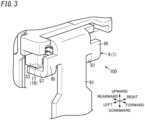
- FIG. 3 is an enlarged view illustrating a main part of the electromagnetic relay 100 according to the present embodiment.
- an upper surface of the extended part 97 and a lower surface of the lower flange 33 of the coil bobbin 3 face each other in the upward and downward direction.
- a tip end of the extended part 97 faces a holding structure (the coil bobbin 3) that holds the regulating member 12.
- the present embodiment includes a seal member 17 provided in a gap between the upper surface of the extended part 97 and the lower surface of the lower flange 33.
- the seal member 17 is provided in a gap between the tip end of the extended part 97 and a counter portion facing the tip end of the extended part 97 in the holding structure that holds the regulating member 12. That is, in the present embodiment, the upper surface of the extended part 97 and the lower surface of the lower flange 33 are not in direct contact with each other but are in contact with each other with the seal member 17 provided therebetween.
- the seal member 17 is, for example, an adhesive made of an epoxy resin.
- the coil bobbin 3 (strictly speaking, the lower flange 33) which is the holding structure that holds the regulating member 12 and the extended part 97 are in contact with each other with the seal member 17 provided therebetween.
- This allows heat transmitted from the movable contact 14 to the second fixed contact 15 upon completion of transition of the contact device A1 from the ON state to the OFF state to be transmitted to the fixed terminal 1 via the regulating member (contact plate) 12, the coil bobbin 3, the seal member 17, the extended part 97, and the second projection 95. Therefore, even in the case of use in a low-temperature environment, the temperature of the fixed terminal 1 does not decrease much, and the temperature of the fixed contact 13 attached to the fixed terminal 1 also does not decrease much.
- the heat transmission 16 includes the regulating member (contact plate) 12, the coil bobbin 3, the seal member 17, the extended part 97, and the second projection 95.
- the heat transmission structure 16 includes the extended part 97 extending from the fixed terminal 1 toward the regulating member 12.
- the heat transmission structure 16 is configured to transmit, to the fixed terminal 1, heat from the movable contact 14 when the movable member 11 is in the open position, through a thermal path R1 (see FIG. 4 ) including at least the regulating member 12.
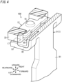
- R1 indicates a thermal path of heat transmitted from the movable contact 14 to the second fixed contact 15. As illustrated in FIGS. 1 and 4 , the thermal path R1 is connected between the fixed contact 13 and the terminal part 91 of the first terminal plate 9 (fixed terminal 1).
- the movable contact 14 When the contact device A1 is in the ON state, the movable contact 14 is in contact with the fixed contact 13 and a current flows between the two contacts, and therefore, the temperature of the movable contact 14 is increasing. The temperature of the coil 4 is also increasing.
- the contact device A1 transitions from the ON state to the OFF state the movable contact 14 moves away from the fixed contact 13 and comes into contact with the second fixed contact 15.
- heat transmitted to the movable contact 14 via the spring pieces 113 of the movable member 11 is transmitted from the movable contact 14 to the second fixed contact 15.
- the heat transmitted to the second fixed contact 15 is transmitted to the regulating member (contact plate) 12 and is then transmitted from the regulating member (contact plate) 12 to the lower flange 33 of the coil bobbin 3. Then, the heat transmitted to the lower flange 33 is transmitted to the terminal part 91 via the seal member 17, the extended part 97, and the second projection 95 (see the thermal path R1 in FIG. 4 ).
- the terminal part 91 of the first terminal plate 9 protrudes out of the case C1.
- the fixed terminal 1 the first terminal plate 9
- the terminal part 91 protruding out of the case C1 which accommodates at least part of the fixed terminal 1. Therefore, when the electromagnetic relay 100 is used at low-temperature environment, the temperature of the one end (lower end) of the terminal part 91 decreases. However, when the heat from the movable contact 14 is transmitted to the terminal part 91 as in the case of the electromagnetic relay 100 of the present embodiment, the temperature of the terminal part 91 in the vicinity of the heat transmission structure 16 does not decrease much.
- the temperature of the fixed contact 13 attached to the other end of the terminal part 91 also does not decrease much. Therefore, it is possible to reduce the temperature difference between the temperature of the fixed contact 13 and the temperature of the vicinity of the fixed contact 13.
- moisture in air around the fixed contact 13 hardly forms condensation and freezes on the fixed contact 13, and it is therefore possible to reduce defects of electrical connection between the contacts due to freezing.
- the first embodiment is only one of various embodiments of the present disclosure. Various modifications may be made to the first embodiment depending on design and the like as long as the object of the present disclosure is achieved. Variations of the first embodiment will be described below. Note that any of the variations to be described below may be combined as appropriate.
- each extended part 97 protrudes rearward from the lower end of a corresponding one of the second projections 95.
- each extended part 97 may protrude rearward from a left end or a right end of the second projections 95.
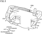
- An electromagnetic relay 100A according to a first variation of the first embodiment will be described below by referring to FIGS. 5 and 6 .
- components other than the fixed terminal 1 (first terminal plate 9) are the same as those of the first embodiment, and therefore, the same components are denoted by the same reference signs as those in the first embodiment, and the detailed description thereof is omitted.
- the first terminal plate 9 (the fixed terminal 1) according to the first variation includes a terminal part 91, a contact part 92 (see FIG. 1 ), a pair of lugs 93 (see FIG. 1 ), a pair of first projections 94, a pair of second projections 95, and a pair of extended parts 97A.
- One of the pair of extended parts 97A protrudes rearward from a left end of a left second projection 95 of the pair of second projections 95, and the other of the pair of extended parts 97A protrudes rearward from a right end of a right second projection 95 of the pair of second projections 95.
- each extended part 97A is in contact with a left side surface or a right side surface of a lower flange 33 of a coil bobbin 3 serving as a holding structure that holds a regulating member (contact plate) 12.
- the lower flange 33 and each of the extended parts 97A may be in direct contact with each other or may be in contact with each other with a seal member provided therebetween.
- R2 indicates a thermal path of heat transmitted from the movable contact 14 to a second fixed contact 15.
- the movable contact 14 When the contact device A1 is in the ON state, the movable contact 14 is in contact with a fixed contact 13, and a current flows between the two contacts, and therefore, the temperature of the movable contact 14 is increasing. The temperature of a coil 4 is also increasing.
- the movable contact 14 moves away from the fixed contact 13 and comes into contact with the second fixed contact 15.
- heat transmitted to the movable contact 14 via spring pieces 113 of a movable member 11 is transmitted from the movable contact 14 to the second fixed contact 15.
- the heat transmitted to the second fixed contact 15 is transmitted to the regulating member (contact plate) 12 and is then transmitted from the regulating member 12 to the lower flange 33 of the coil bobbin 3. Then, the heat transmitted to the lower flange 33 is transmitted to the terminal part 91 via the extended parts 97A, and the second projections 95 (see thermal path R2 in FIG. 6 ).
- the terminal part 91 of the first terminal plate 9 protrudes out of a case C1. Therefore, when the electromagnetic relay 100A is used at low-temperature environment, the temperature of the one end (lower end) of the terminal part 91 decreases. However, when the heat from the movable contact 14 is transmitted to the terminal part 91 as in the case of the electromagnetic relay 100A of the first variation, the temperature of the terminal part 91 in the vicinity of a heat transmission structure 16 does not decrease much. Since the fixed contact 13 is disposed at a location closer to the heat transmission structure 16 than to the one end of the terminal part 91, the temperature of the fixed contact 13 attached to the other end of the terminal part 91 also does not decrease much.
- the extended part 97A is disposed at a location whose ambient temperature is higher than the ambient temperature at the location of the extended part 97 of the electromagnetic relay 100 according to the first embodiment, and therefore, it is possible to increase the temperature of the terminal part 91 as compared to the case of the electromagnetic relay 100. This further reduces defects of electrical connection between the contacts due to freezing as compared to the electromagnetic relay 100.
- the extended part 97 or 97A is provided on both sides of the fixed terminal 1 in the right and left direction.
- the extended part 97 or 97A may be provided on at least one side of the fixed terminal 1 in the right and left direction.
- the heat transmission structure 16 includes at least one extended part 97 or 97A.
- the seal member 17 is provided between the upper surface of the extended part 97 and the lower surface of the lower flange 33 of the coil bobbin 3 which is a holding structure of the regulating member 12.
- the upper surface of the extended part 97 and the lower surface of the lower flange 33 may be in direct contact with each other.
- the tip end of the extended part 97 may be in contact with the holding structure (the coil bobbin 3) that holds the regulating member 12.
- a metallizing process may be performed on the lower surface of the lower flange 33 of the coil bobbin 3, and the upper surface of the extended part 97 and the lower surface of the lower flange 33 may be connected to each other by brazing.
- the coil bobbin 3 which is part of the heat transmission structure 16, is the holding structure of the fixed terminal 1.
- a structure other than the coil bobbin 3 may serve as the holding structure of the fixed terminal 1.
- the seal member 17 is an epoxy resin-based adhesive.
- the seal member 17 is not limited to the epoxy resin-based adhesive but may include a filler or may be conductive.
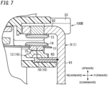
- the present embodiment differs from the first embodiment (including the first variation) in that instead of the extended part 97 or 97A, an intermediate member 18 is disposed between a fixed terminal 1 and a regulating member 12. Note that components other than the intermediate member 18 are the same as those of the first embodiment, and therefore, the same components are denoted by the same reference signs as those in the first embodiment, and the description thereof is omitted.
- An electromagnetic relay 100B includes a contact device A1 (see FIG. 1 ), an electromagnet device B1 (see FIG. 1 ), and a case C1 (see FIG. 1 ).
- the contact device A1 includes a first terminal plate 9 as a fixed terminal 1, a second terminal plate 10 (see FIG. 1 ), a movable member 11, a regulating member (contact plate) 12, and the intermediate member 18.
- the intermediate member 18 is made of, for example, ceramics and has a rectangular shape when viewed in the upward and downward direction.
- a coil bobbin 3 which is a holding structure that holds the fixed terminal 1 and the regulating member 12 is a molded product made of a synthetic resin as described above. That is, the intermediate member 18 has a higher thermal conductivity than the coil bobbin 3 and is electrically insulating. In other words, the intermediate member 18 has a higher thermal conductivity than a material whose component ratio is highest of materials included in a first holding structure that holds the fixed terminal 1 and a second holding structure that holds the regulating member 12, and the intermediate member 18 is electrically insulative.
- the intermediate member 18 is in contact with the regulating member 12 and the fixed terminal 1 in an assembled state of the electromagnetic relay 100B. Specifically, an upper surface of the intermediate member 18 is bonded to a lower surface of the regulating member 12 via, for example, an adhesive. Moreover, the intermediate member 18 has an end which is located at its front surface side and which is bonded to a rear surface of a terminal part 91 of the first terminal plate 9 (the fixed terminal 1) via, for example, an adhesive.
- the coil bobbin 3 which is a holding structure that holds the fixed terminal 1 in the electromagnetic relay 100B of the present embodiment is not included in a heat transmission structure 16.
- the heat transmission structure 16 is a structure that differs from the holding structure (the coil bobbin 3) that holds the fixed terminal 1.
- the heat transmission structure 16 includes the regulating member (contact plate) 12 and the intermediate member 18.
- the movable contact 14 When the contact device A1 is in the ON state, the movable contact 14 is in contact with a fixed contact 13, and a current flows between the two contacts, and therefore, the temperature of the movable contact 14 is increasing. The temperature of a coil 4 is also increasing.
- the contact device A1 transitions from the ON state to the OFF state, the movable contact 14 moves away from the fixed contact 13 and comes into contact with the second fixed contact 15.
- heat transmitted to the movable contact 14 via spring pieces 113 of the movable member 11 is transmitted from the movable contact 14 to the second fixed contact 15.
- the heat transmitted to the second fixed contact 15 is transmitted to the regulating member (contact plate) 12 and is then transmitted from the regulating member 12 to the intermediate member 18. Then, the heat transmitted to the intermediate member 18 is transmitted to the terminal part 91 of the first terminal plate 9 (fixed terminal 1).
- the terminal part 91 of the first terminal plate 9 protrudes out of a case C1. Therefore, when the electromagnetic relay 100B is used at low-temperature environment, the temperature of the one end (lower end) of the terminal part 91 decreases. However, when the heat from the movable contact 14 is transmitted to the terminal part 91 as in the case of the electromagnetic relay 100B of the present embodiment, the temperature of the terminal part 91 in the vicinity of the intermediate member 18 does not decrease much, and the temperature of the fixed contact 13 attached to the other end of the terminal part 91 also does not decrease much. Therefore, it is possible to reduce a temperature difference between the temperature of the fixed contact 13 and the temperature of the vicinity of the fixed contact 13. Thus, according to the electromagnetic relay 100B of the present embodiment, moisture in air around the fixed contact 13 hardly forms condensation and freezes on the fixed contact 13, and it is therefore possible to reduce defects of electrical connection between the contacts due to freezing.
- the second embodiment is only one of various embodiments of the present disclosure. Various modifications may be made to the second embodiment depending on design and the like as long as the object of the present disclosure is achieved. Variations of the second embodiment will be described below. Note that any of the variations to be described below may be combined as appropriate.
- the front surface of the intermediate member 18 is in contact with the rear surface of the terminal part 91 of the first terminal plate 9 (fixed terminal 1).
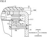
- part of an intermediate member 18A may be inserted into a terminal part 91.
- An electromagnetic relay 100C according to a first variation of the second embodiment will be described below by referring to FIG. 8 .
- components other than the intermediate member 18A and a fixed terminal 1 (first terminal plate 9) are the same as those of the electromagnetic relay 100B of the second embodiment, and therefore, the same components are denoted by the same reference signs as those in the first embodiment, and the detailed description thereof is omitted.
- the first terminal plate 9 (the fixed terminal 1) according to the first variation includes the terminal part 91, a contact part 92, a pair of lugs 93 (see FIG. 1 ), a pair of first projections 94 (see FIG. 1 ), and a pair of second projections 95 (see FIG. 1 ).
- the terminal part 91 has an insertion section 911 penetrating the terminal part 91 in its thickness direction (the forward and rearward direction).
- the insertion section 911 has such a size that the intermediate member 18A is insertable in the insertion section 911.
- the fixed terminal 1 (first terminal plate 9) has the insertion section 911 in which the intermediate member 18A is insertable.
- a front end of the intermediate member 18A is inserted into the insertion section 911 of the terminal part 91.
- the intermediate member 18A is preferably bonded to an inner surface of the insertion section 911 via, for example, an adhesive.
- R4 indicates a thermal path of heat transmitted from the movable contact 14 to a second fixed contact 15.
- the movable contact 14 When a contact device A1 is in the ON state, the movable contact 14 is in contact with a fixed contact 13, and a current flows between the two contacts, and therefore, the temperature of the movable contact 14 is increasing. The temperature of a coil 4 is also increasing.
- the contact device A1 transitions from the ON state to the OFF state, the movable contact 14 moves away from the fixed contact 13 and comes into contact with the second fixed contact 15.
- heat transmitted to the movable contact 14 via spring pieces 113 of a movable member 11 is transmitted from the movable contact 14 to the second fixed contact 15.
- the heat transmitted to the second fixed contact 15 is transmitted to a regulating member (contact plate) 12 and is then transmitted from the regulating member 12 to the intermediate member 18A. Then, the heat transmitted to the intermediate member 18A is transmitted to the terminal part 91.
- the terminal part 91 of the first terminal plate 9 protrudes out of a case C1. Therefore, when the electromagnetic relay 100C is used at low-temperature environment, the temperature of one end (lower end) of the terminal part 91 decreases. However, when the heat from the movable contact 14 is transmitted to the terminal part 91 as in the case of the electromagnetic relay 100C of the first variation, the temperature of the terminal part 91 in the vicinity of the intermediate member 18A does not decrease much, and the temperature of the fixed contact 13 attached to the other end of the terminal part 91 also does not decrease much. Therefore, it is possible to reduce a temperature difference between the temperature of the fixed contact 13 and the temperature of the vicinity of the fixed contact 13. Thus, according to the electromagnetic relay 100C of the first variation, moisture in air around the fixed contact 13 hardly forms condensation and freezes on the fixed contact 13, and it is therefore possible to reduce defects of electrical connection between the contacts due to freezing.
- the regulating member 12 and the intermediate member 18 are separate from each other.
- a regulating member 12 and an intermediate member 18B may be integrated with each other.
- the regulating member 12 and an intermediate member 18B may be an identical member.
- An electromagnetic relay 100D according to a second variation of the second embodiment will be described below by referring to FIG. 9 .
- components other than the regulating member 12 (the intermediate member 18B) are the same as those of the electromagnetic relay 100B of the second embodiment, and therefore, the same components are denoted by the same reference signs as those in the first embodiment, and the detailed description thereof is omitted.
- the intermediate member 18B is an identical member to the terminal plate (regulating member) 12 including a second fixed contact 15.
- the intermediate member 18B is made of, for example, ceramics.
- the intermediate member 18B In a state where the electromagnetic relay 100D is assembled, the intermediate member 18B has an end which is located at its front surface side and which is in contact with a rear surface of a terminal part 91 of a first terminal plate 9 (fixed terminal 1).
- the intermediate member 18B is preferably bonded to the terminal part 91 via, for example, an adhesive.
- a front end of the intermediate member 18B may be configured to be inserted in an insertion section formed in the terminal part 91.
- the movable contact 14 When a contact device A1 is in the ON state, the movable contact 14 is in contact with a fixed contact 13, and a current flows between the two contacts, and therefore, the temperature of the movable contact 14 is increasing. The temperature of a coil 4 is also increasing.
- the contact device A1 transitions from the ON state to the OFF state, the movable contact 14 moves away from the fixed contact 13 and comes into contact with the second fixed contact 15.
- heat transmitted to the movable contact 14 via spring pieces 113 of a movable member 11 is transmitted from the movable contact 14 to the second fixed contact 15.
- the heat transmitted to the second fixed contact 15 is transmitted to the intermediate member 18B (regulating member 12) and is then transmitted from the intermediate member 18B to the terminal part 91.
- the terminal part 91 of the first terminal plate 9 protrudes out of a case C1. Therefore, when the electromagnetic relay 100D is used at low-temperature environment, the temperature of the one end (lower end) of the terminal part 91 decreases. However, when the heat from the movable contact 14 is transmitted to the terminal part 91 as in the case of the electromagnetic relay 100D of the second variation, the temperature of the terminal part 91 in the vicinity of the intermediate member 18B does not decrease much, and the temperature of the fixed contact 13 attached to the other end of the terminal part 91 also does not decrease much. Therefore, it is possible to reduce a temperature difference between the temperature of the fixed contact 13 and the temperature of the vicinity of the fixed contact 13. Thus, according to the electromagnetic relay 100D of the second variation, moisture in air around the fixed contact 13 hardly forms condensation and freezes on the fixed contact 13, and it is therefore possible to reduce defects of electrical connection between the contacts due to freezing.
- the coil bobbin 3 consists of a synthetic resin.
- the coil bobbin 3 may be made of a plurality of materials containing the synthetic resin.
- the synthetic resin having a lower thermal conductivity than the intermediate member 18 has the highest component ratio, using the intermediate member 18 increases the effectiveness of reducing defects of electrical connection between contacts due to freezing.
- the intermediate member 18 is made of ceramics.
- materials for the intermediate member 18 are not limited to ceramics.
- the intermediate member 18 may be made of any other material as long as it has higher thermal conductivity than each of the first holding structure that holds the fixed terminal 1 and the second holding structure that holds the regulating member 12, and it is electrically insulating.
- the configuration described in the second embodiment (including the variations) is accordingly applicable in combination with the configuration (including variations) described in the first embodiment.
- a contact device (A1) of a first aspect includes: a fixed terminal (1), a movable member (11), a regulating member (12), and a heat transmission structure (16).
- the fixed terminal (1) includes a fixed contact (13).
- the movable member (11) includes a movable contact (14) and is configured to move between a closed position where the movable contact (14) is in contact with the fixed contact (13) and an open position where the movable contact (14) is apart from the fixed contact (13).
- the regulating member (12) is configured to be in contact with the movable contact (14) when the movable member (11) is in the open position.
- the heat transmission structure (16) is configured to transmit, to the fixed terminal (1), heat from the movable contact (14) when the movable member (11) is in the open position, through a thermal path (R1 to R5) including at least the regulating member (12).
- This aspect enables heat from the movable contact (14) to be transmitted to the fixed terminal (1) via the heat transmission structure (16), and therefore, the temperature of the fixed terminal (1) is less likely to decrease even when the contact device is used in a low-temperature environment. Therefore, the temperature of the fixed contact (13) does not decrease much, moisture in air around the fixed contact (13) hardly forms condensation and freezes on the fixed contact (13), and it is therefore possible to reduce defects of electrical connection between the contacts due to freezing.
- the heat transmission structure (16) is a structure that differs from a holding structure (a coil bobbin (3)) that holds the fixed terminal (1).
- This aspect enables the degree of freedom of design of the holding structure to be increased as compared to a case where the heat transmission structure (16) and the holding structure are integrated with each other.
- the heat transmission structure (16) includes at least one extended part (97, 97A) extending from the fixed terminal (1) toward the regulating member (12).
- This aspect enables the heat from the movable contact (14) to be transmitted to the fixed terminal (1) via the regulating member (12) and the at least one extended part (97, 97A).
- the at least one extended part (97, 97A) is integrated with the fixed terminal (1).
- This aspect provides the advantage that the thermal conductivity between the at least one extended part (97, 97A) and the fixed terminal (1) is improved as compared to a case where the at least one extended part (97, 97A) is separate from the fixed terminal (1).
- the at least one extended part (97, 97A) includes a plurality of extended parts (97, 97A). At least one of the plurality of extended parts (97, 97A) is provided on a one of both sides of the fixed terminal (1) and a rest of the plurality of extended parts (97, 97A) is provided on the other of the both sides of the fixed terminal (1) in a direction (right and left direction) transverse to a direction (upward and downward direction) in which the fixed contact (13) and the movable contact (14) are aligned with each other.
- This aspect provides the advantage that the heat transfer property is improved as compared to a case where one extended part (97, 97A) is provided.
- the at least one extended part (97, 97A) has a tip end in contact with a holding structure (a coil bobbin 3) that holds the regulating member 12.
- This aspect provides the advantage that the degree of close contact between the holding structure and the at least one extended part (97, 97A) is increased and the thermal conductivity is improved.
- the at least one extended part (97, 97A) has a tip end facing a holding structure (a coil bobbin (3)) that holds the regulating member (12).
- a seal member (17) is provided in a gap between the tip end of the at least one extended part (97, 97A) and a counter portion of the holding structure, the counter portion facing the tip end of the at least one extended part (97, 97A).
- the seal member (17) increases the degree of close contact between the holding structure and the at least one extended part (97, 97A) and improves the thermal conductivity.
- the heat transmission structure (16) includes an intermediate member (18, 18A, 18B) located between the fixed terminal (1) and the regulating member (12).
- the intermediate member (18, 18A, 18B) has a higher thermal conductivity than a material whose component ratio is highest of materials included in a first holding structure that holds the fixed terminal (1) and a second holding structure that holds the regulating member (12), and the intermediate member (18, 18A, 18B) is electrically insulating.
- This aspect enables the heat from movable contact (14) to be transmitted to the fixed terminal (1) via the regulating member (12) in contact with the movable contact (14) and the intermediate member (18, 18A, 18B).
- the intermediate member (18, 18A, 18B) is made of ceramics.
- This aspect enables electrical insulation between the movable contact (14) and the fixed terminal (1) to be secured while heat is transmitted from the movable contact (14) to the fixed terminal (1).
- the regulating member (12) and the intermediate member (18B) are formed as an identical member.
- This aspect provides the advantage that the degree of close contact is increased and thermal conductivity is improved as compared to a case where the regulating member (12) and the intermediate member (18B) are formed as separate members.
- the fixed terminal (1) has an insertion section (911) in which the intermediate member (18A) is insertable.
- This aspect provides the advantage that an area where the fixed terminal (1) and the intermediate member (18A) are in contact with each other is increased, and therefore, the thermal conductivity is improved.
- the fixed terminal (1) has a terminal part (91) protruding out of a case (C1) accommodating at least part of the fixed terminal (1).
- the thermal path (R1 to R5) is connected between the fixed contact (13) and one end of the terminal part (91) of the fixed terminal (1).
- This aspect can make the fixed contact (13) less susceptible to the influence of a temperature drop at the one end of the terminal part (91).
- An electromagnetic relay (100, 100A, 100B, 100C, 100D) of a thirteenth aspect includes: the contact device (A1) of any one of the first to twelfth aspects; and an electromagnet (2) having a coil (4).
- contact device (A1) of any one of the first to twelfth aspects enables defects of electrical connection between the contacts due to freezing to be reduced.
- the electromagnet (2) further includes a coil bobbin (3) around which the coil (4) is wound.
- the fixed terminal (1) and the regulating member (12) are held by the coil bobbin (3).
- This aspect provides the advantage that positional accuracy between the fixed terminal (1) and the regulating member (12) is improved and thermal conductivity is improved as compared to a case where one of the fixed terminal (1) and the regulating member (12) is held by a member other than the coil bobbin (3).
- the configurations of the second to twelfth aspects are not essential to the contact device (A1) and may accordingly be omitted.
- the configuration of the fourteenth aspect is not essential to the electromagnetic relay (100, 100A, 100B, 100C, 100D) and may accordingly be omitted.
Landscapes
- Physics & Mathematics (AREA)
- Electromagnetism (AREA)
- Electromagnets (AREA)
Description
- The present disclosure generally relates to contact devices and electromagnetic relays, and specifically, to a contact device and an electromagnetic relay including a fixed contact and a movable contact.
-
Patent Literature 1 describes an electromagnetic relay for opening and closing contacts by an electromagnet. The electromagnetic relay described inPatent Literature 1 is provided with the contact unit includes a fixed contact and a movable contact which is fixed to a movable spring serving as an electrically conductive flat spring. The fixed contact is connected to a fixed contact terminal and is located on an iron core side of the movable contact to face the movable contact. - The electromagnetic relay described in
Patent Literature 1 has such a configuration that the fixed contact terminal has one end connected to the fixed contact and the other end exposed to an outer side of a housing, and the fixed contact terminal is in contact with outside air. Therefore, when the electromagnetic relay is used in a low-temperature environment, the fixed contact terminal in contact with the outside air rapidly cools the fixed contact, and thereby, air in the vicinity of the fixed contact forms condensation and freezes on the fixed contact, which may lead to a defect of electrical connection between the contacts. - Patent Literature 1:
JP 2010-108656 A - The document
KR 200 425 067 Y1 claim 1. - In view of the foregoing, it is an object of the present disclosure to provide a contact device and an electromagnetic relay configured to reduce defects of electrical connection between contacts caused by freezing.
- A contact device according to one aspect of the present disclosure is defined by appended
claim 1. - An electromagnetic relay according to one aspect of the present disclosure includes the contact device and an electromagnet having a coil.
-
-
FIG. 1 is an exploded perspective view illustrating an electromagnetic relay according to a first embodiment, which is not part of the invention; -
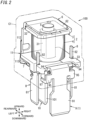
FIG. 2 is an external view illustrating the electromagnetic relay; -
FIG. 3 is an enlarged view illustrating a main part of the electromagnetic relay; -
FIG. 4 is a view illustrating a thermal path in the electromagnetic relay; -
FIG. 5 is an enlarged view illustrating a main part of an electromagnetic relay of a variation of the first embodiment; -
FIG. 6 is a view illustrating a thermal path in the electromagnetic relay of the variation; -
FIG. 7 is a sectional view illustrating a main part of an electromagnetic relay according to a second embodiment, which is the invention; -
FIG. 8 is a sectional view illustrating a main part of an electromagnetic relay according to a first variation of the second embodiment; and -
FIG. 9 is a sectional view illustrating a main part of an electromagnetic relay according to a second variation of the second embodiment. - First Embodiment, which is not part of the invention
- A schema of a contact device A1 and an
electromagnetic relay 100 according to the present embodiment will be described below by referring toFIGS. 1 and2 . - The
electromagnetic relay 100 according to the present embodiment is, for example, a device for switching a supply state of direct-current power from a battery of a vehicle to a load (e.g., a lamp or a motor). In theelectromagnetic relay 100 according to the present embodiment, the contact device A1 is inserted into a supply path of the direct-current power from a power supply such as the battery to the load, and the supply state of the direct-current power from the power supply to the load is switchable by opening and closing the contact device A1. - As illustrated in
FIGS. 1 and2 , the contact device A1 according to the present embodiment includes afixed terminal 1, amovable member 11, a regulatingmember 12, and aheat transmission structure 16. Thefixed terminal 1 includes a fixedcontact 13. Themovable member 11 includes amovable contact 14 and is configured to move between a closed position where themovable contact 14 is in contact with the fixedcontact 13 and an open position where themovable contact 14 is apart from the fixedcontact 13. The regulatingmember 12 is configured to be in contact with themovable contact 14 when themovable member 11 is in the open position. Theheat transmission structure 16 is configured to transmit, to thefixed terminal 1, heat from themovable contact 14 when themovable member 11 is in the open position, through a thermal path R1 (seeFIG. 4 ) including at least the regulatingmember 12. - As illustrated in
FIG. 1 , theelectromagnetic relay 100 according to the present embodiment includes the contact device A1 and anelectromagnet 2 having acoil 4. - The contact device A1 and the
electromagnetic relay 100 according to the present embodiment enable the heat from themovable contact 14 to be transmitted to thefixed terminal 1 via theheat transmission structure 16. Thus, the temperature of thefixed terminal 1 does not decrease much even when the contact device A1 and theelectromagnetic relay 100 are used under a low-temperature environment where an ambient temperature is low (lower than or equal to 0°C) such as in a winter season or in a cold district. Therefore, the temperature of the fixedcontact 13 does not deceases much, moisture in air in the vicinity of the fixedcontact 13 hardly forms condensation and freezes on the fixedcontact 13, and it is therefore possible to reduce defects of electrical connection between the contacts caused by freezing. - Configuration of a contact device A1 and an
electromagnetic relay 100 according to the present embodiment will be described below by referring toFIG. 1 andFIG. 2 . - In the following description, a direction in which the
fixed contact 13 and themovable contact 14 are arranged with each other is referred to as an upward and downward direction, a side on which thefixed contact 13 is provided as viewed from themovable contact 14 is referred to as an upside, and an opposite side to the upside is referred to as a downside. Further, in the following description, a direction in which afirst terminal plate 9 and asecond terminal plate 10 are aligned with each other is referred to as a forward and rearward direction, a side on which thefirst terminal plate 9 is provided when viewed from thesecond terminal plate 10 is referred to as a front side, and an opposite side to the front side is referred to as a back side. Furthermore, in the following description, a direction in which a pair ofcoil terminal plates 8 are aligned with each other is referred to as a right and left direction. - These directions are, however, not intended to define the use direction of the contact device A1 and the
electromagnetic relay 100. Moreover, arrows indicating "forward, "rearward", "right", "left", "upward", and "downward" in the figures are shown for the sake of explanation and are not accompanied with entity. - The
electromagnetic relay 100 according to the present embodiment is a so-called hinge type relay. As illustrated inFIG. 1 , theelectromagnetic relay 100 according to the present embodiment includes the contact device A1, an electromagnet device B1, and a case C1. - As illustrated in
FIGS. 1 and2 , the contact device A1 includes thefirst terminal plate 9 as thefixed terminal 1, thesecond terminal plate 10, themovable member 11, and thecontact plate 12. - The first terminal plate 9 (the fixed terminal 1) is made of a conductive material (e.g., copper or a copper alloy) and is L-shaped when viewed in the right and left direction. The
first terminal plate 9 has aterminal part 91, acontact part 92, a pair oflugs 93, a pair offirst projections 94, a pair ofsecond projections 95, and a pair ofextended parts 97. Theterminal part 91 has a rectangular shape elongated in the upward and downward direction when viewed in the forward and rearward direction. Thecontact part 92 has a rectangular shape elongated in the right and left direction when viewed in the upward and downward direction. The contact part protrudes rearward from an upper end edge of theterminal part 91. Thecontact part 92 has a lower surface to which the fixedcontact 13 is attached by an appropriate attachment method (e.g., fixation by swaging). In other words, thefixed terminal 1 has thefixed contact 13. The fixedcontact 13 is made of, for example, a silver alloy. Thefixed contact 13 may be integrated with or separate from the first terminal plate 9 (the fixed terminal 1). - At the upper end edge of the
terminal part 91, each of the pair oflugs 93 protrudes rearward from a corresponding one of both right and left sides of thecontact part 92. That is, eachrespective lug 93 protrudes in the same orientation (rearward) as thecontact part 92 and is provided at a location away from thecontact part 92. Eachlug 93 has a rectangular shape when viewed in the upward and downward direction. Eachlug 93 has a tip end (a rear end) sloped such that the thickness (dimension in the upward and downward direction) and the width (dimension in the right and left direction) decrease toward a tip of the tip end. - One of the pair of
projections 94 protrudes leftward from a left end of aleft lug 93 of the pair oflugs 93, and the other of the pair ofprojections 94 protrudes rightward from a right end of aright lug 93 of the pair oflugs 93. One of the pair ofsecond projections 95 protrudes leftward from a left end of an upper end of theterminal part 91, and the other of the pair ofsecond projections 95 protrudes rightward from a right end of the upper end of theterminal part 91. The pair offirst projections 94 are provided to be apart from the pair ofsecond projections 95 in a longitudinal direction of theterminal part 91. Thus, it is possible to easily bend the firstterminal plate 9 between the pair offirst projections 94 and the pair ofsecond projections 95. - Each of the pair of
extended parts 97 protrudes rearward from a lower end of each of the pair ofsecond projections 95. In other words, theextended parts 97 are integrated with the fixedterminal 1. Moreover, theextended parts 97 are provided on both sides of the fixedterminal 1 in the right and left direction (a direction transverse to the direction in which the fixedcontact 13 and themovable contact 14 are aligned with each other). Eachextended part 97 has a rectangular shape elongated in the forward and rearward direction when viewed in the upward and downward direction. Theextended parts 97 are preferably integrated with the fixed terminal 1 (the first terminal plate 9) but may be separate from the fixedterminal 1. - The second
terminal plate 10 is made of a conductive material (e.g., copper or a copper alloy) in a similar manner to the firstterminal plate 9. As illustrated inFIG. 1 , the secondterminal plate 10 has aterminal part 101, a fixingpart 102, and acoupler 103. Theterminal part 101 has a rectangular shape elongated in the upward and downward direction when viewed in the right and left direction. The fixingpart 102 has a rectangular shape when viewed in the forward and rearward direction. The fixingpart 102 has a front surface provided with a pair of risingparts 104 protruding forward. The pair of risingparts 104 are aligned with each other in the right and left direction. Each of the pair of risingparts 104 has a round shape when viewed from the front. The pair of risingparts 104 are used to attach the secondterminal plate 10 to themovable member 11. Theterminal part 101 and the fixingpart 102 are integrally formed by thecoupler 103 having a rectangular shape elongated in the upward and downward direction. - The
movable member 11 is a flat spring formed of a conductive thin plate (e.g., a copper plate) and is L-shaped when viewed in the right and left direction. As illustrated inFIG. 1 , themovable member 11 has anoperation piece 111, afixed piece 112, and a pair ofspring pieces 113. Theoperation piece 111 has a triangular shape when viewed in the upward and downward direction. Theoperation piece 111 has a rear end having a pair of fixingholes 114 penetrating theoperation piece 111 in its thickness direction (the upward and downward direction). The pair of fixingholes 114 are aligned with each other in the right and left direction. Each of the pair of fixingholes 114 has a round shape. The pair of fixingholes 114 are used to attach an armature 7 (which will be described later) to themovable member 11. Moreover, theoperation piece 111 has a front end to which themovable contact 14 is attached by an appropriate attachment method (e.g., fixation by swaging). In the present embodiment, themovable contact 14 protrudes upward and downward respectively from an upper surface and a lower surface of theoperation piece 111 such that themovable contact 14 is accessible to the fixedcontact 13 of the firstterminal plate 9 and a second fixed contact 15 (which will be described later) of thecontact plate 12. Themovable contact 14 may be integrated with or separate from themovable member 11. - The fixed
piece 112 has a rectangular shape elongated in the right and left direction when viewed in the forward and rearward direction. The fixedpiece 112 has a lower end having a pair of fixingholes 115 and a pair of fixingholes 116 penetrating the fixedpiece 112 in its thickness direction (the forward and rearward direction). The pair of fixingholes 115 are aligned with each other in the right and left direction. Moreover, the pair of fixingholes 116 are aligned with each other in the right and left direction. Each of the fixingholes holes 115 are provided between the pair of fixingholes 116 in the right and left direction. That is, the distance between the pair of fixingholes 115 is shorter than the space between the pair of fixingholes 116. The pair of fixingholes 115 are used to attach the secondterminal plate 10 to themovable member 11. Specifically, the pair of risingparts 104 inserted in the pair of fixingholes 115 are fixed to themovable member 11 by swaging, thereby attaching the secondterminal plate 10 to themovable member 11. Moreover, the pair of fixingholes 116 are used to attach a yoke 6 (which will be described later) to themovable member 11. Specifically, after a pair of rising parts provided on a rear surface of a first plate 61 (which will be described later) of theyoke 6 are inserted in the pair of fixingholes 116, the pair of rising parts are fixed to themovable member 11 by swaging, thereby attaching theyoke 6 to themovable member 11. - The pair of
spring pieces 113 are bent at an intermediate portion in a longitudinal direction of the pair ofspring pieces 113 and connect theoperation piece 111 to the fixedpiece 112 at both ends of theoperation piece 111 and the fixedpiece 112 in the right and left direction. - The
movable member 11 is configured to warp when the armature 7 is in a first location (location where the armature 7 is in contact with an attraction section 51 (which will be described later)). Then, themovable member 11 attempts to return to an initial state, thereby applying, to the armature 7, force oriented to move the armature 7 from the first location to a second location (location where the armature 7 is apart from the attraction section 51). That is, themovable member 11 is configured to apply, to the armature 7, force which is generated by resilience and which is oriented to move the armature 7 from the first location to the second location. - Here, in the present embodiment, the
movable contact 14 of themovable member 11 is in contact with the fixedcontact 13 when the armature 7 is in the first location, and themovable contact 14 of themovable member 11 is apart from the fixedcontact 13 when the armature 7 is in the second location. That is, the position of themovable member 11 when the armature 7 is in the first location is the closed position, and the position of themovable member 11 when the armature 7 is in the second location is the open position. In other words, themovable member 11 has themovable contact 14 and is configured to move between the closed position where themovable contact 14 is in contact with the fixedcontact 13 and the open position where themovable contact 14 is apart from the fixedcontact 13. - The
contact plate 12 is made of a conductive material (e.g., copper or a copper alloy) and has a rectangular shape elongated in the right and left direction when viewed in the upward and downward direction. As illustrated inFIG. 1 , thecontact plate 12 has asecond contact part 121 and a pair ofsecond lugs 122. Thesecond contact part 121 has a rectangular shape elongated in the right and left direction when viewed in the upward and downward direction. Thesecond contact part 121 has an upper surface to which the second fixedcontact 15 is attached by an appropriate attachment method (e.g., fixation by swaging). The pair ofsecond lugs 122 protrude rearward at locations away from thesecond contact part 121 on both right and left sides of thesecond contact part 121. Thecontact plate 12 is configured such that themovable contact 14 of themovable member 11 is in contact with the second fixedcontact 15 in state where the armature 7 is in the second location. The second fixedcontact 15 is a dummy contact that regulates movement of themovable member 11. That is, thecontact plate 12 is a regulating member (hereinafter also referred to as a "regulatingmember 12") that regulates the movement of themovable member 11, and thecontact plate 12 is in contact with themovable contact 14 when themovable member 11 is in the open position. - As illustrated in
FIGS. 1 and2 , the electromagnet device B1 includes theelectromagnet 2, astator 5, theyoke 6, the armature 7, and the pair ofcoil terminal plates 8. Each of thestator 5, theyoke 6, and the armature 7 is made of a magnetic material. - As illustrated in
FIGS. 1 and2 , theelectromagnet 2 has acoil bobbin 3 and thecoil 4. - The
coil bobbin 3 is made of, for example, an electrically insulating material such as a synthetic resin and is arranged such that an axial direction of thecoil bobbin 3 coincides with the upward and downward direction. Thecoil bobbin 3 includes a windingbody section 31, anupper flange 32, and alower flange 33. The windingbody section 31 has a cylindrical shape elongated in the upward and downward direction and has a hollow 34 through which thestator 5 is inserted. Theupper flange 32 has a rectangular shape when viewed in the upward and downward direction and is integrally formed with one end (upper end) of the windingbody section 31. Theupper flange 32 has a central part having a throughhole 321 being round and penetrating theupper flange 32 in its thickness direction (the upward and downward direction). The throughhole 321 is communicated with the hollow 34 in thebody section 31 in the upward and downward direction. - The
lower flange 33 has a rectangular shape when viewed in the upward and downward direction and is integrally formed with the other end (lower end) of the windingbody section 31. Thelower flange 33 has a central part having a through hole penetrating thelower flange 33 in its thickness direction (the upward and downward direction). The through hole in thelower flange 33 is communicated with the hollow 34 in thebody section 31 in the upward and downward direction. In other words, the hollow 34 in thebody section 31, the throughhole 321 in theupper flange 32, and the through hole in thelower flange 33 constitute a through hole penetrating thecoil bobbin 3 in the upward and downward direction. - The
lower flange 33 includes an accommodation section (first accommodation section) 35, a pair of holders (first holders) 36, and a pair ofseparators 37. Thelower flange 33 further includes a pair ofgrooves 38, asecond accommodation section 39, and a pair ofsecond holders 40. Note that in a structure in which thecoil bobbin 3 does not hold the contact plate (the regulating member) 12, thesecond accommodation section 39 and the pair ofsecond holders 40 may be omitted. - The
accommodation section 35 has a shape of a box whose front surface and lower surface are open. The dimension of theaccommodation section 35 in the forward and rearward direction is larger than the dimension of thecontact part 92 of the firstterminal plate 9 in the forward and rearward direction. The dimension of theaccommodation section 35 in the right and left direction is larger than the dimension (width dimension) of thecontact part 92 in the right and left direction. Moreover, the dimension of theaccommodation section 35 in the upward and downward direction is larger than the dimension (thickness dimension) of thecontact part 92 in the upward and downward direction. That is, in state where thecontact part 92 is accommodated in theaccommodation section 35, thecontact part 92 and theaccommodation section 35 are not in contact with each other. - Each of the pair of
holders 36 is provided on a corresponding one of both right and left sides of theaccommodation section 35. Each of the pair ofholders 36 has a shape of a box whose front surface is open. The pair ofholders 36 and the pair oflugs 93 correspond to each other on a one-to-one basis. Each of the pair oflugs 93 is inserted into a correspondingholder 36 of the pair ofholders 36 and is held by the correspondingholder 36, and thereby, the firstterminal plate 9 is attached to thecoil bobbin 3. - Each of the pair of
separators 37 is provided between theaccommodation section 35 and a corresponding one of theholders 36 in the right and left direction. In the present embodiment, each of the pair ofseparators 37 is a longitudinal wall formed between theaccommodation section 35 and the corresponding one of theholders 36 in the right and left direction. - Each of the pair of
grooves 38 has a U-shape when viewed in the forward and rearward direction and is formed such that an open side of the U-shape is on an inner side in the right and left direction. Theoperation piece 111 of themovable member 11 is disposed in a space formed by the pair ofgrooves 38. Thus, the dimension of eachgroove 38 in the upward and downward direction is a dimension which allows theoperation piece 111 to be moved between the closed position and the open position. - The
second accommodation section 39 has a shape of a box whose front surface, rear surface, and upper surface are open. Each of the pair ofsecond holders 40 is provided on a corresponding one of both right and left side of thesecond accommodation section 39. Thesecond accommodation section 39 and the pair ofsecond holders 40 are used to attach thecontact plate 12, to which the second fixedcontact 15 has been attached, to thecoil bobbin 3. That is, each of thesecond lugs 122 is held by a correspondingsecond holder 40 of the pair ofsecond holders 40, and thereby, thecontact plate 12 is attached to thecoil bobbin 3. At this time, thesecond contact part 121 including the second fixedcontact 15 is accommodated in thesecond accommodation section 39. That is, in the present embodiment, the fixed terminal 1 (the first terminal plate 9) and the regulating member (contact plate) 12 are held by thecoil bobbin 3. - Moreover, the
lower flange 33 has both right and leftsides having grooves 41 in which winding wire sections 82 (which will be described later) of the pair ofcoil terminal plates 8 are to be inserted. - The
coil 4 is formed by winding an electric wire (e.g., copper wire) around thebody section 31 of thecoil bobbin 3. Thecoil 4 is electrically connected to the pair ofcoil terminal plates 8 by winding a first end of the electric wire around the windingwire sections 82 of one of the pair ofcoil terminal plates 8 and a second end of the electric wire around the windingwire section 82 of the other of the pair ofcoil terminal plates 8. Thecoil 4 generates a magnetic flux when supplied with a current via the pair ofcoil terminal plates 8. - The
stator 5 is a columnar iron core elongated in the upward and downward direction. Thestator 5 is inserted in the hollow 34 formed in thecoil bobbin 3 in a state where both ends of thestator 5 in its longitudinal direction (the upward and downward direction) are exposed from thecoil bobbin 3. Thestator 5 has a first end (lower end) in a longitudinal direction of thestator 5, and the first end has a larger diameter than an intermediate portion of thestator 5 and faces the armature 7. In the following description, the first end of thestator 5 is referred to as the "attraction section 51". Moreover, thestator 5 has a second end (upper end) in the longitudinal direction of thestator 5, and the second end is inserted into an insertion hole 621 (which will be described later) in a second plate 62 (which will be described later) of theyoke 6, and thestator 5 is fixed to theyoke 6. - The
Yoke 6, together with thestator 5 and the armature 7, forms a flux path through which a magnetic flux generated when theelectromagnet 2 is energized passes. Theyoke 6 is formed by bending an intermediate portion of a plate having a rectangular shape elongated in the upward and downward direction into an L-shape when viewed in the right and left direction. As illustrated inFIG. 1 , theyoke 6 has thefirst plate 61 and thesecond plate 62. Both thefirst plate 61 and thesecond plate 62 are rectangular. Thesecond plate 62 is located on one end side (an upper side) in an axial direction (the upward and downward direction) of thecoil 4. Thesecond plate 62 has the insertion hole 621 being round and penetrating thesecond plate 62 in its thickness direction (the upward and downward direction). The second end of thestator 5 is inserted into the insertion hole 621. Thefirst plate 61 is located behind thecoil 4. Note that the rear surface of thefirst plate 61 has a pair of rising parts protruding rearward and integrated with the rear surface. After inserting the pair of rising parts into the pair of fixingholes 116 formed in the fixedpiece 112 of themovable member 11 on a one-to-one basis, the pair of rising parts are fixed to the fixedpiece 112 by swaging, and thereby, themovable member 11 is attached to theyoke 6. - The armature 7 has a rectangular shape when viewed in the upward and downward direction. The armature 7 has a lower surface integrally provided with a pair of rising parts protruding downward. After inserting the pair of rising parts into the pair of fixing
holes 114 formed in theoperation piece 111 of themovable member 11 on a one-to-one basis, the pair of rising parts are fixed to theoperation piece 111 by swaging, and thereby, the armature 7 is attached to themovable member 11. - Each of the pair of
coil terminal plates 8 is made of a conductive material (e.g., copper or a copper alloy) in a similar manner to the firstterminal plate 9 and the secondterminal plate 10. As illustrated inFIGS. 1 and2 , each of the pair ofcoil terminal plates 8 has acoil terminal part 81 and the windingwire section 82. Thecoil terminal part 81 has a rectangular shape elongated in the upward and downward direction when viewed in the right and left direction. The windingwire section 82 has a bar shape elongated in the upward and downward direction and is integrally formed on an upper end edge of thecoil terminal part 81. The first end or the second end of the electric wire forming thecoil 4 is wound around the windingwire section 82. - The case C1 has a box shape and is made of an electrically insulating material such as a synthetic resin. As illustrated in
FIG. 1 , the case C1 has a cover C11 and a base C12 having a plate shape. The cover C11 has a shape of a box whose lower surface is open. The base C12 is to be attached to the cover C11 to close the opening at the lower surface of thecover C 11. The case C1 is formed by connecting the cover C11 and the base C12 to each other by, for example, bonding using an adhesive of a thermosetting resin or the like. The case C1 accommodates the contact device A1 and the electromagnet device B1. In a state where the contact device A1 and the electromagnet device B1 are accommodated in the case C1, one end (lower end) of theterminal part 91 of the firstterminal plate 9, a lower end of theterminal part 101 of the secondterminal plate 10, and a lower end of thecoil terminal part 81 of each of the pair ofcoil terminal plates 8 are exposed from the case C 1 (seeFIG. 2 ). - Operation of the
electromagnetic relay 100 according to the present embodiment will be described below. - First of all, closing operation of the contact device A1 will be described. In an OFF state of the contact device A1, the
movable member 11 is located at the open position due to resilient force of the pair ofspring pieces 113. At this time, themovable contact 14 is in contact with the second fixedcontact 15 of thesecond contact part 121 of thecontact plate 12. Moreover, the armature 7 is attached to theoperation piece 111 of themovable member 11 and is thus located at a location (second location) apart from theattraction section 51 of thestator 5. - In the OFF state of the contact device A1, energizing the
coil 4 of theelectromagnet 2 causes thecoil 4 to generate a magnetic flux. This generates magnetic attractive force between the armature 7 and theattraction section 51 of thestator 5 to attract the armature 7 to theattraction section 51 against the resilient force of themovable member 11. Thus, the armature 7 rotates about a fulcrum which is a part of the armature 7 and which is in contact with theyoke 6, and the armature 7 moves from the second location to the first location. - As the armature 7 moves to the first location, the
operation piece 111 of themovable member 11 to which the armature 7 is attached also rotates against the resilient force of the pair ofspring pieces 113. As a result, themovable contact 14 moves away from the second fixedcontact 15 and comes into contact with the fixedcontact 13 of thecontact part 92 of the firstterminal plate 9. Thus, the contact device A1 transitions to an ON state, and the firstterminal plate 9 and the secondterminal plate 10 are electrically connected to each other via the fixedcontact 13 and themovable contact 14. - Next, open operation of the contact device A1 will be described. In the ON state of the contact device A1, de-energizing the
coil 4 of theelectromagnet 2 causes thecoil 4 to no longer generate the magnetic flux. Thus, the magnetic attractive force between the armature 7 and theattraction section 51 of thestator 5 is also lost. Then, the armature 7 rotates in a direction opposite to the direction in the close operation by the resilient force of the pair ofspring pieces 113 of themovable member 11 and moves from the first location to the second location. - As the armature 7 moves to the second location, the
operation piece 111 of themovable member 11 to which the armature 7 is attached is also rotated by the resilient force of the pair ofspring pieces 113 in a direction opposite to the direction in the close operation. As a result, themovable contact 14 moves away from the fixedcontact 13 and comes into contact with the second fixedcontact 15. Thus, the contact device A1 transitions to the OFF state. - The
heat transmission 16 according to the present embodiment will be described below with reference toFIGS. 3 and4 . -
FIG. 3 is an enlarged view illustrating a main part of theelectromagnetic relay 100 according to the present embodiment. In a state where thecoil bobbin 3 holds the fixedterminal 1, an upper surface of theextended part 97 and a lower surface of thelower flange 33 of thecoil bobbin 3 face each other in the upward and downward direction. In other words, a tip end of theextended part 97 faces a holding structure (the coil bobbin 3) that holds the regulatingmember 12. The present embodiment includes aseal member 17 provided in a gap between the upper surface of theextended part 97 and the lower surface of thelower flange 33. In other words, theseal member 17 is provided in a gap between the tip end of theextended part 97 and a counter portion facing the tip end of theextended part 97 in the holding structure that holds the regulatingmember 12. That is, in the present embodiment, the upper surface of theextended part 97 and the lower surface of thelower flange 33 are not in direct contact with each other but are in contact with each other with theseal member 17 provided therebetween. Theseal member 17 is, for example, an adhesive made of an epoxy resin. - Thus, in the
electromagnetic relay 100 according to the present embodiment, the coil bobbin 3 (strictly speaking, the lower flange 33) which is the holding structure that holds the regulatingmember 12 and theextended part 97 are in contact with each other with theseal member 17 provided therebetween. This allows heat transmitted from themovable contact 14 to the second fixedcontact 15 upon completion of transition of the contact device A1 from the ON state to the OFF state to be transmitted to the fixedterminal 1 via the regulating member (contact plate) 12, thecoil bobbin 3, theseal member 17, theextended part 97, and thesecond projection 95. Therefore, even in the case of use in a low-temperature environment, the temperature of the fixedterminal 1 does not decrease much, and the temperature of the fixedcontact 13 attached to the fixedterminal 1 also does not decrease much. Therefore, it is possible to reduce a temperature difference between the temperature of the fixedcontact 13 and the temperature of the vicinity of the fixedcontact 13. Thus, moisture in air around the fixedcontact 13 hardly forms condensation and freezes on the fixedcontact 13, and it is thus possible to reduce defects of electrical connection between the contacts (defects of electrical connection between the fixedcontact 13 and the movable contact 14) due to freezing. - In the present embodiment, the
heat transmission 16 includes the regulating member (contact plate) 12, thecoil bobbin 3, theseal member 17, theextended part 97, and thesecond projection 95. In other words, theheat transmission structure 16 includes theextended part 97 extending from the fixedterminal 1 toward the regulatingmember 12. Moreover, theheat transmission structure 16 is configured to transmit, to the fixedterminal 1, heat from themovable contact 14 when themovable member 11 is in the open position, through a thermal path R1 (seeFIG. 4 ) including at least the regulatingmember 12. - Next, operation of transmitting heat from the
movable contact 14 to the fixedterminal 1 will be described with reference toFIG. 4 . InFIG. 4 , "R1" indicates a thermal path of heat transmitted from themovable contact 14 to the second fixedcontact 15. As illustrated inFIGS. 1 and4 , the thermal path R1 is connected between the fixedcontact 13 and theterminal part 91 of the first terminal plate 9 (fixed terminal 1). - When the contact device A1 is in the ON state, the
movable contact 14 is in contact with the fixedcontact 13 and a current flows between the two contacts, and therefore, the temperature of themovable contact 14 is increasing. The temperature of thecoil 4 is also increasing. When the contact device A1 transitions from the ON state to the OFF state, themovable contact 14 moves away from the fixedcontact 13 and comes into contact with the second fixedcontact 15. Of heat generated at themovable contact 14 and heat generated at thecoil 4, heat transmitted to themovable contact 14 via thespring pieces 113 of themovable member 11 is transmitted from themovable contact 14 to the second fixedcontact 15. The heat transmitted to the second fixedcontact 15 is transmitted to the regulating member (contact plate) 12 and is then transmitted from the regulating member (contact plate) 12 to thelower flange 33 of thecoil bobbin 3. Then, the heat transmitted to thelower flange 33 is transmitted to theterminal part 91 via theseal member 17, theextended part 97, and the second projection 95 (see the thermal path R1 inFIG. 4 ). - Here, in a state where the
electromagnetic relay 100 is assembled, as shown inFIG. 2 , theterminal part 91 of the first terminal plate 9 (fixed terminal 1) protrudes out of the case C1. In other words, the fixed terminal 1 (the first terminal plate 9) has theterminal part 91 protruding out of the case C1 which accommodates at least part of the fixedterminal 1. Therefore, when theelectromagnetic relay 100 is used at low-temperature environment, the temperature of the one end (lower end) of theterminal part 91 decreases. However, when the heat from themovable contact 14 is transmitted to theterminal part 91 as in the case of theelectromagnetic relay 100 of the present embodiment, the temperature of theterminal part 91 in the vicinity of theheat transmission structure 16 does not decrease much. Since the fixedcontact 13 is disposed at a location closer to theheat transmission structure 16 than to the one end of theterminal part 91, the temperature of the fixedcontact 13 attached to the other end of theterminal part 91 also does not decrease much. Therefore, it is possible to reduce the temperature difference between the temperature of the fixedcontact 13 and the temperature of the vicinity of the fixedcontact 13. Thus, according to theelectromagnetic relay 100 of the present embodiment, moisture in air around the fixedcontact 13 hardly forms condensation and freezes on the fixedcontact 13, and it is therefore possible to reduce defects of electrical connection between the contacts due to freezing. - The first embodiment is only one of various embodiments of the present disclosure. Various modifications may be made to the first embodiment depending on design and the like as long as the object of the present disclosure is achieved. Variations of the first embodiment will be described below. Note that any of the variations to be described below may be combined as appropriate.
- In the first embodiment, each
extended part 97 protrudes rearward from the lower end of a corresponding one of thesecond projections 95. However, as illustrated inFIG. 5 , eachextended part 97 may protrude rearward from a left end or a right end of thesecond projections 95. Anelectromagnetic relay 100A according to a first variation of the first embodiment will be described below by referring toFIGS. 5 and6 . Note that components other than the fixed terminal 1 (first terminal plate 9) are the same as those of the first embodiment, and therefore, the same components are denoted by the same reference signs as those in the first embodiment, and the detailed description thereof is omitted. - As illustrated in
FIG. 5 , the first terminal plate 9 (the fixed terminal 1) according to the first variation includes aterminal part 91, a contact part 92 (seeFIG. 1 ), a pair of lugs 93 (seeFIG. 1 ), a pair offirst projections 94, a pair ofsecond projections 95, and a pair ofextended parts 97A. One of the pair ofextended parts 97A protrudes rearward from a left end of a leftsecond projection 95 of the pair ofsecond projections 95, and the other of the pair ofextended parts 97A protrudes rearward from a right end of a rightsecond projection 95 of the pair ofsecond projections 95. - In a state where the
electromagnetic relay 100A is assembled, eachextended part 97A is in contact with a left side surface or a right side surface of alower flange 33 of acoil bobbin 3 serving as a holding structure that holds a regulating member (contact plate) 12. Note that thelower flange 33 and each of theextended parts 97A may be in direct contact with each other or may be in contact with each other with a seal member provided therebetween. - Next, operation of transmitting heat from a
movable contact 14 to the fixedterminal 1 will be described with reference toFIG. 6 . InFIG. 6 , "R2" indicates a thermal path of heat transmitted from themovable contact 14 to a second fixedcontact 15. - When the contact device A1 is in the ON state, the
movable contact 14 is in contact with a fixedcontact 13, and a current flows between the two contacts, and therefore, the temperature of themovable contact 14 is increasing. The temperature of acoil 4 is also increasing. When a contact device A1 transitions from the ON state to the OFF state, themovable contact 14 moves away from the fixedcontact 13 and comes into contact with the second fixedcontact 15. Of heat generated at themovable contact 14 and heat generated at thecoil 4, heat transmitted to themovable contact 14 viaspring pieces 113 of amovable member 11 is transmitted from themovable contact 14 to the second fixedcontact 15. The heat transmitted to the second fixedcontact 15 is transmitted to the regulating member (contact plate) 12 and is then transmitted from the regulatingmember 12 to thelower flange 33 of thecoil bobbin 3. Then, the heat transmitted to thelower flange 33 is transmitted to theterminal part 91 via theextended parts 97A, and the second projections 95 (see thermal path R2 inFIG. 6 ). - Here, in a state where the
electromagnetic relay 100A is assembled, theterminal part 91 of the first terminal plate 9 (fixed terminal 1) protrudes out of a case C1. Therefore, when theelectromagnetic relay 100A is used at low-temperature environment, the temperature of the one end (lower end) of theterminal part 91 decreases. However, when the heat from themovable contact 14 is transmitted to theterminal part 91 as in the case of theelectromagnetic relay 100A of the first variation, the temperature of theterminal part 91 in the vicinity of aheat transmission structure 16 does not decrease much. Since the fixedcontact 13 is disposed at a location closer to theheat transmission structure 16 than to the one end of theterminal part 91, the temperature of the fixedcontact 13 attached to the other end of theterminal part 91 also does not decrease much. Therefore, it is possible to reduce a temperature difference between the temperature of the fixedcontact 13 and the temperature of the vicinity of the fixedcontact 13. Thus, according to theelectromagnetic relay 100A of the first variation, moisture in air around the fixedcontact 13 hardly forms condensation and freezes on the fixedcontact 13, and it is therefore possible to reduce defects of electrical connection between the contacts due to freezing. - According to the
electromagnetic relay 100A of the first variation, theextended part 97A is disposed at a location whose ambient temperature is higher than the ambient temperature at the location of theextended part 97 of theelectromagnetic relay 100 according to the first embodiment, and therefore, it is possible to increase the temperature of theterminal part 91 as compared to the case of theelectromagnetic relay 100. This further reduces defects of electrical connection between the contacts due to freezing as compared to theelectromagnetic relay 100. - Other variations are listed below.
- In the first embodiment or the first variation, the
extended part terminal 1 in the right and left direction. However, theextended part terminal 1 in the right and left direction. In other words, theheat transmission structure 16 includes at least oneextended part - In the first embodiment, the
seal member 17 is provided between the upper surface of theextended part 97 and the lower surface of thelower flange 33 of thecoil bobbin 3 which is a holding structure of the regulatingmember 12. However, the upper surface of theextended part 97 and the lower surface of thelower flange 33 may be in direct contact with each other. In other words, the tip end of theextended part 97 may be in contact with the holding structure (the coil bobbin 3) that holds the regulatingmember 12. This configuration provides the advantage that direct contact between the upper surface of theextended part 97 and the lower surface of thelower flange 33 improves the heat-transfer efficiency. - Moreover, in place of the
seal member 17, a metallizing process may be performed on the lower surface of thelower flange 33 of thecoil bobbin 3, and the upper surface of theextended part 97 and the lower surface of thelower flange 33 may be connected to each other by brazing. - In the first embodiment, a description is given of, for example, a case where the
coil bobbin 3, which is part of theheat transmission structure 16, is the holding structure of the fixedterminal 1. However, a structure other than thecoil bobbin 3 may serve as the holding structure of the fixedterminal 1. - In the first embodiment, a description is given of, for example, a case where the
seal member 17 is an epoxy resin-based adhesive. However, theseal member 17 is not limited to the epoxy resin-based adhesive but may include a filler or may be conductive. - Second Embodiment, which is the invention
- The present embodiment differs from the first embodiment (including the first variation) in that instead of the
extended part intermediate member 18 is disposed between afixed terminal 1 and a regulatingmember 12. Note that components other than theintermediate member 18 are the same as those of the first embodiment, and therefore, the same components are denoted by the same reference signs as those in the first embodiment, and the description thereof is omitted. - An
electromagnetic relay 100B according to the present embodiment includes a contact device A1 (seeFIG. 1 ), an electromagnet device B1 (seeFIG. 1 ), and a case C1 (seeFIG. 1 ). - As illustrated in
FIG. 7 , the contact device A1 includes a firstterminal plate 9 as afixed terminal 1, a second terminal plate 10 (seeFIG. 1 ), amovable member 11, a regulating member (contact plate) 12, and theintermediate member 18. - The
intermediate member 18 is made of, for example, ceramics and has a rectangular shape when viewed in the upward and downward direction. Here, acoil bobbin 3 which is a holding structure that holds the fixedterminal 1 and the regulatingmember 12 is a molded product made of a synthetic resin as described above. That is, theintermediate member 18 has a higher thermal conductivity than thecoil bobbin 3 and is electrically insulating. In other words, theintermediate member 18 has a higher thermal conductivity than a material whose component ratio is highest of materials included in a first holding structure that holds the fixedterminal 1 and a second holding structure that holds the regulatingmember 12, and theintermediate member 18 is electrically insulative. - The
intermediate member 18 is in contact with the regulatingmember 12 and the fixedterminal 1 in an assembled state of theelectromagnetic relay 100B. Specifically, an upper surface of theintermediate member 18 is bonded to a lower surface of the regulatingmember 12 via, for example, an adhesive. Moreover, theintermediate member 18 has an end which is located at its front surface side and which is bonded to a rear surface of aterminal part 91 of the first terminal plate 9 (the fixed terminal 1) via, for example, an adhesive. Unlike theelectromagnetic relay coil bobbin 3, which is a holding structure that holds the fixedterminal 1 in theelectromagnetic relay 100B of the present embodiment is not included in aheat transmission structure 16. In other words, theheat transmission structure 16 is a structure that differs from the holding structure (the coil bobbin 3) that holds the fixedterminal 1. In the present embodiment, theheat transmission structure 16 includes the regulating member (contact plate) 12 and theintermediate member 18. - Next, operation of transmitting heat from a
movable contact 14 to the fixedterminal 1 will be described with reference toFIG. 7 . InFIG. 7 , "R3" indicates a thermal path of heat transmitted from themovable contact 14 to a second fixedcontact 15. - When the contact device A1 is in the ON state, the
movable contact 14 is in contact with a fixedcontact 13, and a current flows between the two contacts, and therefore, the temperature of themovable contact 14 is increasing. The temperature of acoil 4 is also increasing. When the contact device A1 transitions from the ON state to the OFF state, themovable contact 14 moves away from the fixedcontact 13 and comes into contact with the second fixedcontact 15. Of heat generated at themovable contact 14 and heat generated at thecoil 4, heat transmitted to themovable contact 14 viaspring pieces 113 of themovable member 11 is transmitted from themovable contact 14 to the second fixedcontact 15. The heat transmitted to the second fixedcontact 15 is transmitted to the regulating member (contact plate) 12 and is then transmitted from the regulatingmember 12 to theintermediate member 18. Then, the heat transmitted to theintermediate member 18 is transmitted to theterminal part 91 of the first terminal plate 9 (fixed terminal 1). - Here, in a state where the
electromagnetic relay 100B is assembled, theterminal part 91 of the first terminal plate 9 (fixed terminal 1) protrudes out of a case C1. Therefore, when theelectromagnetic relay 100B is used at low-temperature environment, the temperature of the one end (lower end) of theterminal part 91 decreases. However, when the heat from themovable contact 14 is transmitted to theterminal part 91 as in the case of theelectromagnetic relay 100B of the present embodiment, the temperature of theterminal part 91 in the vicinity of theintermediate member 18 does not decrease much, and the temperature of the fixedcontact 13 attached to the other end of theterminal part 91 also does not decrease much. Therefore, it is possible to reduce a temperature difference between the temperature of the fixedcontact 13 and the temperature of the vicinity of the fixedcontact 13. Thus, according to theelectromagnetic relay 100B of the present embodiment, moisture in air around the fixedcontact 13 hardly forms condensation and freezes on the fixedcontact 13, and it is therefore possible to reduce defects of electrical connection between the contacts due to freezing. - The second embodiment is only one of various embodiments of the present disclosure. Various modifications may be made to the second embodiment depending on design and the like as long as the object of the present disclosure is achieved. Variations of the second embodiment will be described below. Note that any of the variations to be described below may be combined as appropriate.
- In the second embodiment, the front surface of the
intermediate member 18 is in contact with the rear surface of theterminal part 91 of the first terminal plate 9 (fixed terminal 1). However, as illustrated inFIG. 8 , part of anintermediate member 18A may be inserted into aterminal part 91. An electromagnetic relay 100C according to a first variation of the second embodiment will be described below by referring toFIG. 8 . Note that components other than theintermediate member 18A and a fixed terminal 1 (first terminal plate 9) are the same as those of theelectromagnetic relay 100B of the second embodiment, and therefore, the same components are denoted by the same reference signs as those in the first embodiment, and the detailed description thereof is omitted. - As illustrated in
FIG. 8 , the first terminal plate 9 (the fixed terminal 1) according to the first variation includes theterminal part 91, acontact part 92, a pair of lugs 93 (seeFIG. 1 ), a pair of first projections 94 (seeFIG. 1 ), and a pair of second projections 95 (seeFIG. 1 ). Theterminal part 91 has aninsertion section 911 penetrating theterminal part 91 in its thickness direction (the forward and rearward direction). Theinsertion section 911 has such a size that theintermediate member 18A is insertable in theinsertion section 911. In other words, the fixed terminal 1 (first terminal plate 9) has theinsertion section 911 in which theintermediate member 18A is insertable. - In a state where the electromagnetic relay 100C is assembled, a front end of the
intermediate member 18A is inserted into theinsertion section 911 of theterminal part 91. Note that theintermediate member 18A is preferably bonded to an inner surface of theinsertion section 911 via, for example, an adhesive. - Next, operation of transmitting heat from a
movable contact 14 to the fixedterminal 1 will be described with reference toFIG. 8 . InFIG. 8 , "R4" indicates a thermal path of heat transmitted from themovable contact 14 to a second fixedcontact 15. - When a contact device A1 is in the ON state, the
movable contact 14 is in contact with a fixedcontact 13, and a current flows between the two contacts, and therefore, the temperature of themovable contact 14 is increasing. The temperature of acoil 4 is also increasing. When the contact device A1 transitions from the ON state to the OFF state, themovable contact 14 moves away from the fixedcontact 13 and comes into contact with the second fixedcontact 15. Of heat generated at themovable contact 14 and heat generated at thecoil 4, heat transmitted to themovable contact 14 viaspring pieces 113 of amovable member 11 is transmitted from themovable contact 14 to the second fixedcontact 15. The heat transmitted to the second fixedcontact 15 is transmitted to a regulating member (contact plate) 12 and is then transmitted from the regulatingmember 12 to theintermediate member 18A. Then, the heat transmitted to theintermediate member 18A is transmitted to theterminal part 91. - Here, in a state where the electromagnetic relay 100C is assembled, the
terminal part 91 of the first terminal plate 9 (fixed terminal 1) protrudes out of a case C1. Therefore, when the electromagnetic relay 100C is used at low-temperature environment, the temperature of one end (lower end) of theterminal part 91 decreases. However, when the heat from themovable contact 14 is transmitted to theterminal part 91 as in the case of the electromagnetic relay 100C of the first variation, the temperature of theterminal part 91 in the vicinity of theintermediate member 18A does not decrease much, and the temperature of the fixedcontact 13 attached to the other end of theterminal part 91 also does not decrease much. Therefore, it is possible to reduce a temperature difference between the temperature of the fixedcontact 13 and the temperature of the vicinity of the fixedcontact 13. Thus, according to the electromagnetic relay 100C of the first variation, moisture in air around the fixedcontact 13 hardly forms condensation and freezes on the fixedcontact 13, and it is therefore possible to reduce defects of electrical connection between the contacts due to freezing. - In the second embodiment, the regulating
member 12 and theintermediate member 18 are separate from each other. However, as illustrated inFIG. 9 , a regulatingmember 12 and anintermediate member 18B may be integrated with each other. In other words, the regulatingmember 12 and anintermediate member 18B may be an identical member. Anelectromagnetic relay 100D according to a second variation of the second embodiment will be described below by referring toFIG. 9 . Note that components other than the regulating member 12 (theintermediate member 18B) are the same as those of theelectromagnetic relay 100B of the second embodiment, and therefore, the same components are denoted by the same reference signs as those in the first embodiment, and the detailed description thereof is omitted. - As illustrated in
FIG. 9 , theintermediate member 18B according to the second variation is an identical member to the terminal plate (regulating member) 12 including a second fixedcontact 15. Theintermediate member 18B is made of, for example, ceramics. In a state where theelectromagnetic relay 100D is assembled, theintermediate member 18B has an end which is located at its front surface side and which is in contact with a rear surface of aterminal part 91 of a first terminal plate 9 (fixed terminal 1). Note that theintermediate member 18B is preferably bonded to theterminal part 91 via, for example, an adhesive. Alternatively, a front end of theintermediate member 18B may be configured to be inserted in an insertion section formed in theterminal part 91. - Next, operation of transmitting heat from a
movable contact 14 to the fixedterminal 1 will be described with reference toFIG. 9 . InFIG. 9 , "R5" indicates a thermal path of heat transmitted from themovable contact 14 to the second fixedcontact 15. - When a contact device A1 is in the ON state, the
movable contact 14 is in contact with a fixedcontact 13, and a current flows between the two contacts, and therefore, the temperature of themovable contact 14 is increasing. The temperature of acoil 4 is also increasing. When the contact device A1 transitions from the ON state to the OFF state, themovable contact 14 moves away from the fixedcontact 13 and comes into contact with the second fixedcontact 15. Of heat generated at themovable contact 14 and heat generated at thecoil 4, heat transmitted to themovable contact 14 viaspring pieces 113 of amovable member 11 is transmitted from themovable contact 14 to the second fixedcontact 15. The heat transmitted to the second fixedcontact 15 is transmitted to theintermediate member 18B (regulating member 12) and is then transmitted from theintermediate member 18B to theterminal part 91. - Here, in a state where the
electromagnetic relay 100D is assembled, theterminal part 91 of the first terminal plate 9 (fixed terminal 1) protrudes out of a case C1. Therefore, when theelectromagnetic relay 100D is used at low-temperature environment, the temperature of the one end (lower end) of theterminal part 91 decreases. However, when the heat from themovable contact 14 is transmitted to theterminal part 91 as in the case of theelectromagnetic relay 100D of the second variation, the temperature of theterminal part 91 in the vicinity of theintermediate member 18B does not decrease much, and the temperature of the fixedcontact 13 attached to the other end of theterminal part 91 also does not decrease much. Therefore, it is possible to reduce a temperature difference between the temperature of the fixedcontact 13 and the temperature of the vicinity of the fixedcontact 13. Thus, according to theelectromagnetic relay 100D of the second variation, moisture in air around the fixedcontact 13 hardly forms condensation and freezes on the fixedcontact 13, and it is therefore possible to reduce defects of electrical connection between the contacts due to freezing. - Other variations are listed below.
- In the second embodiment, the
coil bobbin 3 consists of a synthetic resin. However, thecoil bobbin 3 may be made of a plurality of materials containing the synthetic resin. Here, when of the plurality of materials, the synthetic resin having a lower thermal conductivity than theintermediate member 18 has the highest component ratio, using theintermediate member 18 increases the effectiveness of reducing defects of electrical connection between contacts due to freezing. - In the second embodiment, the description is given of the case where the
intermediate member 18 is made of ceramics. However, materials for theintermediate member 18 are not limited to ceramics. Theintermediate member 18 may be made of any other material as long as it has higher thermal conductivity than each of the first holding structure that holds the fixedterminal 1 and the second holding structure that holds the regulatingmember 12, and it is electrically insulating. - The configuration described in the second embodiment (including the variations) is accordingly applicable in combination with the configuration (including variations) described in the first embodiment.
- As described above, a contact device (A1) of a first aspect includes: a fixed terminal (1), a movable member (11), a regulating member (12), and a heat transmission structure (16). The fixed terminal (1) includes a fixed contact (13). The movable member (11) includes a movable contact (14) and is configured to move between a closed position where the movable contact (14) is in contact with the fixed contact (13) and an open position where the movable contact (14) is apart from the fixed contact (13). The regulating member (12) is configured to be in contact with the movable contact (14) when the movable member (11) is in the open position. The heat transmission structure (16) is configured to transmit, to the fixed terminal (1), heat from the movable contact (14) when the movable member (11) is in the open position, through a thermal path (R1 to R5) including at least the regulating member (12).
- This aspect enables heat from the movable contact (14) to be transmitted to the fixed terminal (1) via the heat transmission structure (16), and therefore, the temperature of the fixed terminal (1) is less likely to decrease even when the contact device is used in a low-temperature environment. Therefore, the temperature of the fixed contact (13) does not decrease much, moisture in air around the fixed contact (13) hardly forms condensation and freezes on the fixed contact (13), and it is therefore possible to reduce defects of electrical connection between the contacts due to freezing.
- In a contact device (A1) of a second aspect referring to the first aspect, the heat transmission structure (16) is a structure that differs from a holding structure (a coil bobbin (3)) that holds the fixed terminal (1).
- This aspect enables the degree of freedom of design of the holding structure to be increased as compared to a case where the heat transmission structure (16) and the holding structure are integrated with each other.
- In a contact device (A1) of a third aspect referring to the first or second aspect, the heat transmission structure (16) includes at least one extended part (97, 97A) extending from the fixed terminal (1) toward the regulating member (12).
- This aspect enables the heat from the movable contact (14) to be transmitted to the fixed terminal (1) via the regulating member (12) and the at least one extended part (97, 97A).
- In a contact device (A1) of a fourth aspect referring to the third aspect, the at least one extended part (97, 97A) is integrated with the fixed terminal (1).
- This aspect provides the advantage that the thermal conductivity between the at least one extended part (97, 97A) and the fixed terminal (1) is improved as compared to a case where the at least one extended part (97, 97A) is separate from the fixed terminal (1).
- In a contact device (A1) of a fifth aspect referring to the third or fourth aspect, the at least one extended part (97, 97A) includes a plurality of extended parts (97, 97A). At least one of the plurality of extended parts (97, 97A) is provided on a one of both sides of the fixed terminal (1) and a rest of the plurality of extended parts (97, 97A) is provided on the other of the both sides of the fixed terminal (1) in a direction (right and left direction) transverse to a direction (upward and downward direction) in which the fixed contact (13) and the movable contact (14) are aligned with each other.
- This aspect provides the advantage that the heat transfer property is improved as compared to a case where one extended part (97, 97A) is provided.
- In a contact device (A1) of a sixth aspect referring to any one of the third to fifth aspects, the at least one extended part (97, 97A) has a tip end in contact with a holding structure (a coil bobbin 3) that holds the regulating
member 12. - This aspect provides the advantage that the degree of close contact between the holding structure and the at least one extended part (97, 97A) is increased and the thermal conductivity is improved.
- In a contact device (A1) of a seventh aspect referring to any one of the third to fifth aspects, the at least one extended part (97, 97A) has a tip end facing a holding structure (a coil bobbin (3)) that holds the regulating member (12). In the contact device (A1), a seal member (17) is provided in a gap between the tip end of the at least one extended part (97, 97A) and a counter portion of the holding structure, the counter portion facing the tip end of the at least one extended part (97, 97A).
- With this aspect, the seal member (17) increases the degree of close contact between the holding structure and the at least one extended part (97, 97A) and improves the thermal conductivity.
- In a contact device (A1) of an eighth aspect, which is the invention, referring to the first or second aspect, the heat transmission structure (16) includes an intermediate member (18, 18A, 18B) located between the fixed terminal (1) and the regulating member (12). The intermediate member (18, 18A, 18B) has a higher thermal conductivity than a material whose component ratio is highest of materials included in a first holding structure that holds the fixed terminal (1) and a second holding structure that holds the regulating member (12), and the intermediate member (18, 18A, 18B) is electrically insulating.
- This aspect enables the heat from movable contact (14) to be transmitted to the fixed terminal (1) via the regulating member (12) in contact with the movable contact (14) and the intermediate member (18, 18A, 18B).
- In a contact device (A1) of a ninth aspect referring to the eighth aspect, the intermediate member (18, 18A, 18B) is made of ceramics.
- This aspect enables electrical insulation between the movable contact (14) and the fixed terminal (1) to be secured while heat is transmitted from the movable contact (14) to the fixed terminal (1).
- In a contact device (A1) of a tenth aspect referring to the eighth or ninth aspect, the regulating member (12) and the intermediate member (18B) are formed as an identical member.
- This aspect provides the advantage that the degree of close contact is increased and thermal conductivity is improved as compared to a case where the regulating member (12) and the intermediate member (18B) are formed as separate members.
- In a contact device (A1) of an eleventh aspect referring to any one of the eighth to tenth aspects, the fixed terminal (1) has an insertion section (911) in which the intermediate member (18A) is insertable.
- This aspect provides the advantage that an area where the fixed terminal (1) and the intermediate member (18A) are in contact with each other is increased, and therefore, the thermal conductivity is improved.
- In a contact device (A1) of a twelfth aspect referring to any one of the first to eleventh aspects, the fixed terminal (1) has a terminal part (91) protruding out of a case (C1) accommodating at least part of the fixed terminal (1). The thermal path (R1 to R5) is connected between the fixed contact (13) and one end of the terminal part (91) of the fixed terminal (1).
- This aspect can make the fixed contact (13) less susceptible to the influence of a temperature drop at the one end of the terminal part (91).
- An electromagnetic relay (100, 100A, 100B, 100C, 100D) of a thirteenth aspect includes: the contact device (A1) of any one of the first to twelfth aspects; and an electromagnet (2) having a coil (4).
- According to this aspect, use of the contact device (A1) of any one of the first to twelfth aspects enables defects of electrical connection between the contacts due to freezing to be reduced.
- In an electromagnetic relay (100, 100A, 100B, 100C, 100D) according to a fourteenth aspect referring to the thirteenth aspect, the electromagnet (2) further includes a coil bobbin (3) around which the coil (4) is wound. The fixed terminal (1) and the regulating member (12) are held by the coil bobbin (3).
- This aspect provides the advantage that positional accuracy between the fixed terminal (1) and the regulating member (12) is improved and thermal conductivity is improved as compared to a case where one of the fixed terminal (1) and the regulating member (12) is held by a member other than the coil bobbin (3).
- The configurations of the second to twelfth aspects are not essential to the contact device (A1) and may accordingly be omitted.
- The configuration of the fourteenth aspect is not essential to the electromagnetic relay (100, 100A, 100B, 100C, 100D) and may accordingly be omitted.
-
- 1
- FIXED TERMINAL
- 13
- FIXED CONTACT
- 91
- TERMINAL PART
- 911
- INSERTION SECTION
- 97, 97A
- EXTENDED PART
- 2
- ELECTROMAGNET
- 3
- COIL BOBBIN
- 4
- COIL
- 11
- MOVABLE MEMBER
- 14
- MOVABLE CONTACT
- 12
- CONTACT PLATE (REGULATING MEMBER)
- 16
- HEAT TRANSMISSION STRUCTURE
- 17
- SEAL MEMBER
- 18, 18A, 18B
- INTERMEDIATE MEMBER
- 100, 100A, 100B, 100C, 100D
- ELECTROMAGNETIC RELAY
- A1
- CONTACT DEVICE
- C1
- CASE
Claims (13)
- A contact device, comprising:a fixed terminal (1) including a fixed contact (13);a movable member (11) including a movable contact (14) and being configured to move between a closed position where the movable contact (14) is in contact with the fixed contact (13) and an open position where the movable contact (14) is apart from the fixed contact (13);a regulating member (12) configured to be in contact with the movable contact (14) when the movable member (11) is in the open position; anda heat transmission structure (16) configured to transmit, to the fixed terminal (1), heat from the movable contact (14) when the movable member (11) is in the open position, through a thermal path (R1, R2, R3, R4, R5) including at least the regulating member (12);characterized in thatthe heat transmission structure (16) includes an intermediate member (18, 18A, 18B) located between the fixed terminal (1) and the regulating member (12), andthe intermediate member (18, 18A, 18B) has a higher thermal conductivity than a material whose component ratio is highest of materials included in a first holding structure that holds the fixed terminal (1) and a second holding structure that holds the regulating member (12), and the intermediate member (18, 18A, 18B) is electrically insulating.
- The contact device of claim 1, wherein
the heat transmission structure (16) is a structure that differs from a holding structure that holds the fixed terminal (1). - The contact device of claim 1 or 2, wherein
the heat transmission structure (16) includes at least one extended part (97, 97A) extending from the fixed terminal (1) toward the regulating member (12). - The contact device of claim 3, wherein
the at least one extended part (97, 97A) is integrated with the fixed terminal (1). - The contact device of claim 3 or 4, whereinthe at least one extended part (97, 97A) includes a plurality of extended parts (97, 97A), andat least one of the plurality of extended parts (97, 97A) is provided on one of both sides of the fixed terminal (1) and a rest of the plurality of extended parts (97, 97A) is provided on the other of the both sides of the fixed terminal (1) in a direction transverse to a direction in which the fixed contact (13) and the movable contact (14) are aligned with each other.
- The contact device of any one of claims 3 to 5, wherein
the at least one extended part (97, 97A) has a tip end in contact with a holding structure that holds the regulating member (12). - The contact device of any one of claims 3 to 5, whereinthe at least one extended part (97, 97A) has a tip end facing a holding structure that holds the regulating member (12), anda seal member (17) is provided in a gap between the tip end of the at least one extended part (97, 97A) and a counter portion of the holding structure, the counter portion facing the tip end of the at least one extended part (97, 97A).
- The contact device of any one of claims 1 to 7, wherein
the intermediate member (18, 18A, 18B) is made of ceramics. - The contact device of any one of claims 1 to 8, wherein
the regulating member (12) and the intermediate member (18, 18A, 18B) are formed as an identical member. - The contact device of any one of claims 1 to 9, wherein
the fixed terminal (1) has an insertion section (911) in which the intermediate member (18, 18A, 18B) is insertable. - The contact device of any one of claims 1 to 10, whereinthe fixed terminal (1) has a terminal part (91) protruding out of a case (C1) accommodating at least part of the fixed terminal (1), andthe thermal path (R4, R5) is connected between the fixed contact (13) and one end of the terminal part (91) of the fixed terminal (1).
- An electromagnetic relay, comprising:the contact device (A1) of any one of claims 1 to 11; andan electromagnet (2) having a coil (4).
- The electromagnetic relay of claim 12, whereinthe electromagnet (2) further includes a coil bobbin (3) around which the coil (4) is wound, andthe fixed terminal (1) and the regulating member (12) are held by the coil bobbin (3).
Applications Claiming Priority (2)
| Application Number | Priority Date | Filing Date | Title |
|---|---|---|---|
| JP2017238044A JP7029284B2 (en) | 2017-12-12 | 2017-12-12 | Contact devices and electromagnetic relays |
| PCT/JP2018/042778 WO2019116837A1 (en) | 2017-12-12 | 2018-11-20 | Contact device and electromagnetic relay |
Publications (3)
| Publication Number | Publication Date |
|---|---|
| EP3726559A1 EP3726559A1 (en) | 2020-10-21 |
| EP3726559A4 EP3726559A4 (en) | 2020-12-16 |
| EP3726559B1 true EP3726559B1 (en) | 2023-06-28 |
Family
ID=66820006
Family Applications (1)
| Application Number | Title | Priority Date | Filing Date |
|---|---|---|---|
| EP18889326.7A Active EP3726559B1 (en) | 2017-12-12 | 2018-11-20 | Contact device and electromagnetic relay |
Country Status (5)
| Country | Link |
|---|---|
| US (1) | US11302500B2 (en) |
| EP (1) | EP3726559B1 (en) |
| JP (1) | JP7029284B2 (en) |
| CN (1) | CN111466007A (en) |
| WO (1) | WO2019116837A1 (en) |
Families Citing this family (6)
| Publication number | Priority date | Publication date | Assignee | Title |
|---|---|---|---|---|
| CN110797233B (en) * | 2019-11-01 | 2025-05-30 | 厦门宏发汽车电子有限公司 | An electromagnetic relay |
| JP7711541B2 (en) * | 2021-10-05 | 2025-07-23 | オムロン株式会社 | electromagnetic relay |
| USD1021814S1 (en) * | 2022-03-17 | 2024-04-09 | Song Chuan Precision Co., Ltd. | Relay assembly |
| USD1021815S1 (en) * | 2022-03-23 | 2024-04-09 | Song Chuan Precision Co., Ltd. | Relay base |
| USD1026832S1 (en) * | 2022-03-23 | 2024-05-14 | Song Chuan Precision Co., Ltd. | Relay |
| JP2024048420A (en) * | 2022-09-28 | 2024-04-09 | 株式会社Subaru | Relay System |
Family Cites Families (8)
| Publication number | Priority date | Publication date | Assignee | Title |
|---|---|---|---|---|
| DE1564756B1 (en) * | 1966-11-12 | 1970-10-01 | Rau Swf Autozubehoer | Electromagnetic relay |
| KR200425067Y1 (en) * | 2006-04-28 | 2006-09-01 | 한국오므론전장주식회사 | Silent mini relay |
| JP4826617B2 (en) | 2008-10-28 | 2011-11-30 | パナソニック電工株式会社 | Electromagnetic switchgear |
| JP4826618B2 (en) | 2008-10-28 | 2011-11-30 | パナソニック電工株式会社 | Electromagnetic relay |
| JP2013196763A (en) | 2012-03-15 | 2013-09-30 | Omron Corp | Electromagnetic relay |
| US20140247099A1 (en) | 2013-03-01 | 2014-09-04 | Lear Corporation | Apparatus and method for preventing a relay from freezing |
| JP6277795B2 (en) * | 2014-03-14 | 2018-02-14 | オムロン株式会社 | Electromagnetic relay |
| JP6993088B2 (en) | 2017-01-31 | 2022-01-13 | 株式会社Soken | Electromagnetic relay |
-
2017
- 2017-12-12 JP JP2017238044A patent/JP7029284B2/en active Active
-
2018
- 2018-11-20 US US16/771,501 patent/US11302500B2/en active Active
- 2018-11-20 WO PCT/JP2018/042778 patent/WO2019116837A1/en not_active Ceased
- 2018-11-20 CN CN201880080076.6A patent/CN111466007A/en active Pending
- 2018-11-20 EP EP18889326.7A patent/EP3726559B1/en active Active
Also Published As
| Publication number | Publication date |
|---|---|
| EP3726559A1 (en) | 2020-10-21 |
| CN111466007A (en) | 2020-07-28 |
| EP3726559A4 (en) | 2020-12-16 |
| US11302500B2 (en) | 2022-04-12 |
| JP2019106294A (en) | 2019-06-27 |
| WO2019116837A1 (en) | 2019-06-20 |
| US20210183602A1 (en) | 2021-06-17 |
| JP7029284B2 (en) | 2022-03-03 |
Similar Documents
| Publication | Publication Date | Title |
|---|---|---|
| US11302500B2 (en) | Contact device and electromagnetic relay | |
| CN110323104B (en) | Relay with a movable contact | |
| US8659372B2 (en) | Electromagnetic relay | |
| US8203403B2 (en) | Electrical switching devices having moveable terminals | |
| CN102024625B (en) | Electromagnetic relay | |
| US8471656B2 (en) | Electromagnetic relay | |
| CN103311053B (en) | Electromagnetic relay | |
| JP6069127B2 (en) | Electromagnetic relay module | |
| JP2009277361A (en) | Electromagnetic relay | |
| US11133140B2 (en) | Contact device and electromagnetic relay | |
| CN114388304B (en) | Electromagnetic relay | |
| US20180053615A1 (en) | Electromagnetic relay and relay device | |
| US10347452B2 (en) | Polarized DC electromagnetic device and electromagnetic contactor using same | |
| US10373789B2 (en) | Electromagnetic relay | |
| JP6934636B2 (en) | Electromagnetic relay | |
| JP2021082402A (en) | Electromagnetic relay module and electric connection device | |
| WO2020090263A1 (en) | Relay | |
| JP6123269B2 (en) | Magnetic contactor | |
| JP2011008973A (en) | Electromagnetic relay | |
| WO2025182827A1 (en) | Relay | |
| JP4826617B2 (en) | Electromagnetic switchgear | |
| JP2014053200A5 (en) | ||
| JP4091012B2 (en) | Circuit breaker | |
| JP2019053922A (en) | Relay device and connection structure between relay device and relay box | |
| JP2025043191A (en) | Electromagnetic Relay |
Legal Events
| Date | Code | Title | Description |
|---|---|---|---|
| STAA | Information on the status of an ep patent application or granted ep patent |
Free format text: STATUS: THE INTERNATIONAL PUBLICATION HAS BEEN MADE |
|
| PUAI | Public reference made under article 153(3) epc to a published international application that has entered the european phase |
Free format text: ORIGINAL CODE: 0009012 |
|
| STAA | Information on the status of an ep patent application or granted ep patent |
Free format text: STATUS: REQUEST FOR EXAMINATION WAS MADE |
|
| 17P | Request for examination filed |
Effective date: 20200605 |
|
| AK | Designated contracting states |
Kind code of ref document: A1 Designated state(s): AL AT BE BG CH CY CZ DE DK EE ES FI FR GB GR HR HU IE IS IT LI LT LU LV MC MK MT NL NO PL PT RO RS SE SI SK SM TR |
|
| AX | Request for extension of the european patent |
Extension state: BA ME |
|
| A4 | Supplementary search report drawn up and despatched |
Effective date: 20201113 |
|
| RIC1 | Information provided on ipc code assigned before grant |
Ipc: H01H 50/12 20060101AFI20201109BHEP Ipc: H01H 50/64 20060101ALI20201109BHEP Ipc: H01H 50/54 20060101ALI20201109BHEP Ipc: H01H 50/62 20060101ALI20201109BHEP Ipc: H01H 50/14 20060101ALI20201109BHEP |
|
| DAV | Request for validation of the european patent (deleted) | ||
| DAX | Request for extension of the european patent (deleted) | ||
| GRAP | Despatch of communication of intention to grant a patent |
Free format text: ORIGINAL CODE: EPIDOSNIGR1 |
|
| STAA | Information on the status of an ep patent application or granted ep patent |
Free format text: STATUS: GRANT OF PATENT IS INTENDED |
|
| INTG | Intention to grant announced |
Effective date: 20230127 |
|
| GRAS | Grant fee paid |
Free format text: ORIGINAL CODE: EPIDOSNIGR3 |
|
| GRAA | (expected) grant |
Free format text: ORIGINAL CODE: 0009210 |
|
| STAA | Information on the status of an ep patent application or granted ep patent |
Free format text: STATUS: THE PATENT HAS BEEN GRANTED |
|
| AK | Designated contracting states |
Kind code of ref document: B1 Designated state(s): AL AT BE BG CH CY CZ DE DK EE ES FI FR GB GR HR HU IE IS IT LI LT LU LV MC MK MT NL NO PL PT RO RS SE SI SK SM TR |
|
| REG | Reference to a national code |
Ref country code: CH Ref legal event code: EP |
|
| REG | Reference to a national code |
Ref country code: AT Ref legal event code: REF Ref document number: 1583489 Country of ref document: AT Kind code of ref document: T Effective date: 20230715 |
|
| REG | Reference to a national code |
Ref country code: IE Ref legal event code: FG4D |
|
| REG | Reference to a national code |
Ref country code: DE Ref legal event code: R096 Ref document number: 602018052640 Country of ref document: DE |
|
| REG | Reference to a national code |
Ref country code: LT Ref legal event code: MG9D |
|
| PG25 | Lapsed in a contracting state [announced via postgrant information from national office to epo] |
Ref country code: SE Free format text: LAPSE BECAUSE OF FAILURE TO SUBMIT A TRANSLATION OF THE DESCRIPTION OR TO PAY THE FEE WITHIN THE PRESCRIBED TIME-LIMIT Effective date: 20230628 Ref country code: NO Free format text: LAPSE BECAUSE OF FAILURE TO SUBMIT A TRANSLATION OF THE DESCRIPTION OR TO PAY THE FEE WITHIN THE PRESCRIBED TIME-LIMIT Effective date: 20230928 |
|
| REG | Reference to a national code |
Ref country code: NL Ref legal event code: MP Effective date: 20230628 |
|
| REG | Reference to a national code |
Ref country code: AT Ref legal event code: MK05 Ref document number: 1583489 Country of ref document: AT Kind code of ref document: T Effective date: 20230628 |
|
| PG25 | Lapsed in a contracting state [announced via postgrant information from national office to epo] |
Ref country code: RS Free format text: LAPSE BECAUSE OF FAILURE TO SUBMIT A TRANSLATION OF THE DESCRIPTION OR TO PAY THE FEE WITHIN THE PRESCRIBED TIME-LIMIT Effective date: 20230628 Ref country code: NL Free format text: LAPSE BECAUSE OF FAILURE TO SUBMIT A TRANSLATION OF THE DESCRIPTION OR TO PAY THE FEE WITHIN THE PRESCRIBED TIME-LIMIT Effective date: 20230628 Ref country code: LV Free format text: LAPSE BECAUSE OF FAILURE TO SUBMIT A TRANSLATION OF THE DESCRIPTION OR TO PAY THE FEE WITHIN THE PRESCRIBED TIME-LIMIT Effective date: 20230628 Ref country code: LT Free format text: LAPSE BECAUSE OF FAILURE TO SUBMIT A TRANSLATION OF THE DESCRIPTION OR TO PAY THE FEE WITHIN THE PRESCRIBED TIME-LIMIT Effective date: 20230628 Ref country code: HR Free format text: LAPSE BECAUSE OF FAILURE TO SUBMIT A TRANSLATION OF THE DESCRIPTION OR TO PAY THE FEE WITHIN THE PRESCRIBED TIME-LIMIT Effective date: 20230628 Ref country code: GR Free format text: LAPSE BECAUSE OF FAILURE TO SUBMIT A TRANSLATION OF THE DESCRIPTION OR TO PAY THE FEE WITHIN THE PRESCRIBED TIME-LIMIT Effective date: 20230929 |
|
| PG25 | Lapsed in a contracting state [announced via postgrant information from national office to epo] |
Ref country code: FI Free format text: LAPSE BECAUSE OF FAILURE TO SUBMIT A TRANSLATION OF THE DESCRIPTION OR TO PAY THE FEE WITHIN THE PRESCRIBED TIME-LIMIT Effective date: 20230628 |
|
| PG25 | Lapsed in a contracting state [announced via postgrant information from national office to epo] |
Ref country code: SK Free format text: LAPSE BECAUSE OF FAILURE TO SUBMIT A TRANSLATION OF THE DESCRIPTION OR TO PAY THE FEE WITHIN THE PRESCRIBED TIME-LIMIT Effective date: 20230628 |
|
| PG25 | Lapsed in a contracting state [announced via postgrant information from national office to epo] |
Ref country code: ES Free format text: LAPSE BECAUSE OF FAILURE TO SUBMIT A TRANSLATION OF THE DESCRIPTION OR TO PAY THE FEE WITHIN THE PRESCRIBED TIME-LIMIT Effective date: 20230628 |
|
| PG25 | Lapsed in a contracting state [announced via postgrant information from national office to epo] |
Ref country code: IS Free format text: LAPSE BECAUSE OF FAILURE TO SUBMIT A TRANSLATION OF THE DESCRIPTION OR TO PAY THE FEE WITHIN THE PRESCRIBED TIME-LIMIT Effective date: 20231028 |
|
| PG25 | Lapsed in a contracting state [announced via postgrant information from national office to epo] |
Ref country code: SM Free format text: LAPSE BECAUSE OF FAILURE TO SUBMIT A TRANSLATION OF THE DESCRIPTION OR TO PAY THE FEE WITHIN THE PRESCRIBED TIME-LIMIT Effective date: 20230628 Ref country code: SK Free format text: LAPSE BECAUSE OF FAILURE TO SUBMIT A TRANSLATION OF THE DESCRIPTION OR TO PAY THE FEE WITHIN THE PRESCRIBED TIME-LIMIT Effective date: 20230628 Ref country code: RO Free format text: LAPSE BECAUSE OF FAILURE TO SUBMIT A TRANSLATION OF THE DESCRIPTION OR TO PAY THE FEE WITHIN THE PRESCRIBED TIME-LIMIT Effective date: 20230628 Ref country code: PT Free format text: LAPSE BECAUSE OF FAILURE TO SUBMIT A TRANSLATION OF THE DESCRIPTION OR TO PAY THE FEE WITHIN THE PRESCRIBED TIME-LIMIT Effective date: 20231030 Ref country code: IS Free format text: LAPSE BECAUSE OF FAILURE TO SUBMIT A TRANSLATION OF THE DESCRIPTION OR TO PAY THE FEE WITHIN THE PRESCRIBED TIME-LIMIT Effective date: 20231028 Ref country code: ES Free format text: LAPSE BECAUSE OF FAILURE TO SUBMIT A TRANSLATION OF THE DESCRIPTION OR TO PAY THE FEE WITHIN THE PRESCRIBED TIME-LIMIT Effective date: 20230628 Ref country code: EE Free format text: LAPSE BECAUSE OF FAILURE TO SUBMIT A TRANSLATION OF THE DESCRIPTION OR TO PAY THE FEE WITHIN THE PRESCRIBED TIME-LIMIT Effective date: 20230628 Ref country code: CZ Free format text: LAPSE BECAUSE OF FAILURE TO SUBMIT A TRANSLATION OF THE DESCRIPTION OR TO PAY THE FEE WITHIN THE PRESCRIBED TIME-LIMIT Effective date: 20230628 Ref country code: AT Free format text: LAPSE BECAUSE OF FAILURE TO SUBMIT A TRANSLATION OF THE DESCRIPTION OR TO PAY THE FEE WITHIN THE PRESCRIBED TIME-LIMIT Effective date: 20230628 |
|
| PG25 | Lapsed in a contracting state [announced via postgrant information from national office to epo] |
Ref country code: PL Free format text: LAPSE BECAUSE OF FAILURE TO SUBMIT A TRANSLATION OF THE DESCRIPTION OR TO PAY THE FEE WITHIN THE PRESCRIBED TIME-LIMIT Effective date: 20230628 |
|
| REG | Reference to a national code |
Ref country code: DE Ref legal event code: R097 Ref document number: 602018052640 Country of ref document: DE |
|
| PG25 | Lapsed in a contracting state [announced via postgrant information from national office to epo] |
Ref country code: DK Free format text: LAPSE BECAUSE OF FAILURE TO SUBMIT A TRANSLATION OF THE DESCRIPTION OR TO PAY THE FEE WITHIN THE PRESCRIBED TIME-LIMIT Effective date: 20230628 |
|
| PLBE | No opposition filed within time limit |
Free format text: ORIGINAL CODE: 0009261 |
|
| STAA | Information on the status of an ep patent application or granted ep patent |
Free format text: STATUS: NO OPPOSITION FILED WITHIN TIME LIMIT |
|
| PG25 | Lapsed in a contracting state [announced via postgrant information from national office to epo] |
Ref country code: IT Free format text: LAPSE BECAUSE OF FAILURE TO SUBMIT A TRANSLATION OF THE DESCRIPTION OR TO PAY THE FEE WITHIN THE PRESCRIBED TIME-LIMIT Effective date: 20230628 |
|
| 26N | No opposition filed |
Effective date: 20240402 |
|
| REG | Reference to a national code |
Ref country code: CH Ref legal event code: PL |
|
| PG25 | Lapsed in a contracting state [announced via postgrant information from national office to epo] |
Ref country code: MC Free format text: LAPSE BECAUSE OF FAILURE TO SUBMIT A TRANSLATION OF THE DESCRIPTION OR TO PAY THE FEE WITHIN THE PRESCRIBED TIME-LIMIT Effective date: 20230628 |
|
| PG25 | Lapsed in a contracting state [announced via postgrant information from national office to epo] |
Ref country code: LU Free format text: LAPSE BECAUSE OF NON-PAYMENT OF DUE FEES Effective date: 20231120 |
|
| PG25 | Lapsed in a contracting state [announced via postgrant information from national office to epo] |
Ref country code: CH Free format text: LAPSE BECAUSE OF NON-PAYMENT OF DUE FEES Effective date: 20231130 |
|
| GBPC | Gb: european patent ceased through non-payment of renewal fee |
Effective date: 20231120 |
|
| PG25 | Lapsed in a contracting state [announced via postgrant information from national office to epo] |
Ref country code: MC Free format text: LAPSE BECAUSE OF FAILURE TO SUBMIT A TRANSLATION OF THE DESCRIPTION OR TO PAY THE FEE WITHIN THE PRESCRIBED TIME-LIMIT Effective date: 20230628 Ref country code: LU Free format text: LAPSE BECAUSE OF NON-PAYMENT OF DUE FEES Effective date: 20231120 Ref country code: CH Free format text: LAPSE BECAUSE OF NON-PAYMENT OF DUE FEES Effective date: 20231130 Ref country code: SI Free format text: LAPSE BECAUSE OF FAILURE TO SUBMIT A TRANSLATION OF THE DESCRIPTION OR TO PAY THE FEE WITHIN THE PRESCRIBED TIME-LIMIT Effective date: 20230628 |
|
| REG | Reference to a national code |
Ref country code: BE Ref legal event code: MM Effective date: 20231130 |
|
| REG | Reference to a national code |
Ref country code: IE Ref legal event code: MM4A |
|
| PG25 | Lapsed in a contracting state [announced via postgrant information from national office to epo] |
Ref country code: IE Free format text: LAPSE BECAUSE OF NON-PAYMENT OF DUE FEES Effective date: 20231120 |
|
| PG25 | Lapsed in a contracting state [announced via postgrant information from national office to epo] |
Ref country code: GB Free format text: LAPSE BECAUSE OF NON-PAYMENT OF DUE FEES Effective date: 20231120 |
|
| PG25 | Lapsed in a contracting state [announced via postgrant information from national office to epo] |
Ref country code: BE Free format text: LAPSE BECAUSE OF NON-PAYMENT OF DUE FEES Effective date: 20231130 |
|
| PG25 | Lapsed in a contracting state [announced via postgrant information from national office to epo] |
Ref country code: FR Free format text: LAPSE BECAUSE OF NON-PAYMENT OF DUE FEES Effective date: 20231130 |
|
| PG25 | Lapsed in a contracting state [announced via postgrant information from national office to epo] |
Ref country code: IE Free format text: LAPSE BECAUSE OF NON-PAYMENT OF DUE FEES Effective date: 20231120 Ref country code: GB Free format text: LAPSE BECAUSE OF NON-PAYMENT OF DUE FEES Effective date: 20231120 Ref country code: FR Free format text: LAPSE BECAUSE OF NON-PAYMENT OF DUE FEES Effective date: 20231130 Ref country code: BE Free format text: LAPSE BECAUSE OF NON-PAYMENT OF DUE FEES Effective date: 20231130 |
|
| PG25 | Lapsed in a contracting state [announced via postgrant information from national office to epo] |
Ref country code: BG Free format text: LAPSE BECAUSE OF FAILURE TO SUBMIT A TRANSLATION OF THE DESCRIPTION OR TO PAY THE FEE WITHIN THE PRESCRIBED TIME-LIMIT Effective date: 20230628 |
|
| PG25 | Lapsed in a contracting state [announced via postgrant information from national office to epo] |
Ref country code: BG Free format text: LAPSE BECAUSE OF FAILURE TO SUBMIT A TRANSLATION OF THE DESCRIPTION OR TO PAY THE FEE WITHIN THE PRESCRIBED TIME-LIMIT Effective date: 20230628 |
|
| PGFP | Annual fee paid to national office [announced via postgrant information from national office to epo] |
Ref country code: DE Payment date: 20241121 Year of fee payment: 7 |
|
| PG25 | Lapsed in a contracting state [announced via postgrant information from national office to epo] |
Ref country code: CY Free format text: LAPSE BECAUSE OF FAILURE TO SUBMIT A TRANSLATION OF THE DESCRIPTION OR TO PAY THE FEE WITHIN THE PRESCRIBED TIME-LIMIT; INVALID AB INITIO Effective date: 20181120 |
|
| PG25 | Lapsed in a contracting state [announced via postgrant information from national office to epo] |
Ref country code: HU Free format text: LAPSE BECAUSE OF FAILURE TO SUBMIT A TRANSLATION OF THE DESCRIPTION OR TO PAY THE FEE WITHIN THE PRESCRIBED TIME-LIMIT; INVALID AB INITIO Effective date: 20181120 |
|
| PG25 | Lapsed in a contracting state [announced via postgrant information from national office to epo] |
Ref country code: TR Free format text: LAPSE BECAUSE OF FAILURE TO SUBMIT A TRANSLATION OF THE DESCRIPTION OR TO PAY THE FEE WITHIN THE PRESCRIBED TIME-LIMIT Effective date: 20230628 |